ORNL/TM-2017/363 STATUS SUMMARY OF CHEMICAL PROCESSING DEVELOPMENT IN PLUTONIUM-238 SUPPLY PROGRAM D. W. DePaoli D. E. Benker L. H. Delmau S. R. Sherman E. D. Collins R. M. Wham October 6, 2017 Approved for public release. Distribution is unlimited.
Transcript
ORNL/TM-2017/363
STATUS SUMMARY OF CHEMICAL PROCESSING DEVELOPMENT IN PLUTONIUM-238 SUPPLY PROGRAM
D. W. DePaoli D. E. Benker L. H. Delmau S. R. Sherman E. D. Collins R. M. Wham
October 6, 2017 Approved for public release. Distribution is unlimited.
DOCUMENT AVAILABILITY Reports produced after January 1, 1996, are generally available free via US Department of Energy (DOE) SciTech Connect. Website http://www.osti.gov/scitech/ Reports produced before January 1, 1996, may be purchased by members of the public from the following source: National Technical Information Service 5285 Port Royal Road Springfield, VA 22161 Telephone 703-605-6000 (1-800-553-6847) TDD 703-487-4639 Fax 703-605-6900 E-mail [email protected] Website http://classic.ntis.gov/ Reports are available to DOE employees, DOE contractors, Energy Technology Data Exchange representatives, and International Nuclear Information System representatives from the following source: Office of Scientific and Technical Information PO Box 62 Oak Ridge, TN 37831 Telephone 865-576-8401 Fax 865-576-5728 E-mail [email protected] Website http://www.osti.gov/contact.html
This report was prepared as an account of work sponsored by an agency of the United States Government. Neither the United States Government nor any agency thereof, nor any of their employees, makes any warranty, express or implied, or assumes any legal liability or responsibility for the accuracy, completeness, or usefulness of any information, apparatus, product, or process disclosed, or represents that its use would not infringe privately owned rights. Reference herein to any specific commercial product, process, or service by trade name, trademark, manufacturer, or otherwise, does not necessarily constitute or imply its endorsement, recommendation, or favoring by the United States Government or any agency thereof. The views and opinions of authors expressed herein do not necessarily state or reflect those of the United States Government or any agency thereof.
STATUS SUMMARY OF CHEMICAL PROCESSING DEVELOPMENT IN PLUTONIUM-238 SUPPLY PROGRAM
David W. DePaoli Dennis E. Benker Lætitia H. Delmau Steven R. Sherman Emory D. Collins Robert M. Wham
Date Published: October 6, 2017
Prepared by OAK RIDGE NATIONAL LABORATORY
Oak Ridge, TN 37831-6283 managed by
UT-BATTELLE, LLC for the
US DEPARTMENT OF ENERGY under contract DE-AC05-00OR22725
iii
CONTENTS
LIST OF FIGURES ...................................................................................................................................... v LIST OF TABLES ........................................................................................................................................ v ACRONYMS .............................................................................................................................................. vii FOREWORD ............................................................................................................................................... ix ACKNOWLEDGMENTS ........................................................................................................................... xi 1. SUMMARY .......................................................................................................................................... 1
1.1 STATE OF DEVELOPMENT OF PROCESS STEPS ............................................................... 2 1.2 KEY ISSUES TO RESOLVE ..................................................................................................... 8
1.2.1 Neptunium Recycling and Cleanup for Target Fabrication ........................................... 8 1.2.2 Organic Disposition ....................................................................................................... 9 1.2.3 Thorium Removal .......................................................................................................... 9 1.2.4 Effects of Organic Degradation on Solvent Extraction Performance ............................ 9 1.2.5 Recycle of Reject Np Materials from Target Fabrication ............................................ 10 1.2.6 Acceptability of Heat Source PuO2 .............................................................................. 10 1.2.7 Operability ................................................................................................................... 11
2. DISCUSSION OF CHEMICAL PROCESSING................................................................................ 13 2.1 APPROACH ............................................................................................................................. 13
2.1.2 ORNL Process Approach ............................................................................................. 14 2.2 PROCESS ELEMENTS ........................................................................................................... 18
2.2.1 Dissolution of NpO2 ..................................................................................................... 18 2.2.2 Protactinium Removal ................................................................................................. 19 2.2.3 Plutonium/thorium Removal from Neptunium Solution ............................................. 19 2.2.4 Pre-dissolution Hardware Removal from Targets........................................................ 20 2.2.5 Aluminum Dissolution of Irradiated Targets ............................................................... 20 2.2.6 Nitric Acid Dissolution of Irradiated Pellets ................................................................ 23 2.2.7 Solvent Extraction to Separate Np, Pu, and Fission Product Streams ......................... 24 2.2.8 Solvent Regeneration ................................................................................................... 38 2.2.9 Purification of Recycle Np ........................................................................................... 40 2.2.10 Cation Exchange for Purification of 238Pu Stream ....................................................... 44 2.2.11 Conversion to Oxide .................................................................................................... 46 2.2.12 Dissolution of Unirradiated Targets and Pellets .......................................................... 50
3. OUTLOOK TO CAMPAIGN 3 ......................................................................................................... 51 3.1 CAMPAIGN 3 GOALS ............................................................................................................ 51 3.2 PROJECTED SCHEDULE....................................................................................................... 52 3.3 ITEMS IN DEVELOPMENT ................................................................................................... 52
Figure 1. Chemical processing within overall 238Pu production steps. ......................................................... 1 Figure 2. State of development of steps in chemical processing. ................................................................. 3 Figure 3. Three 16-stage continuous countercurrent mixer-settlers installed in cubicle 5 used for
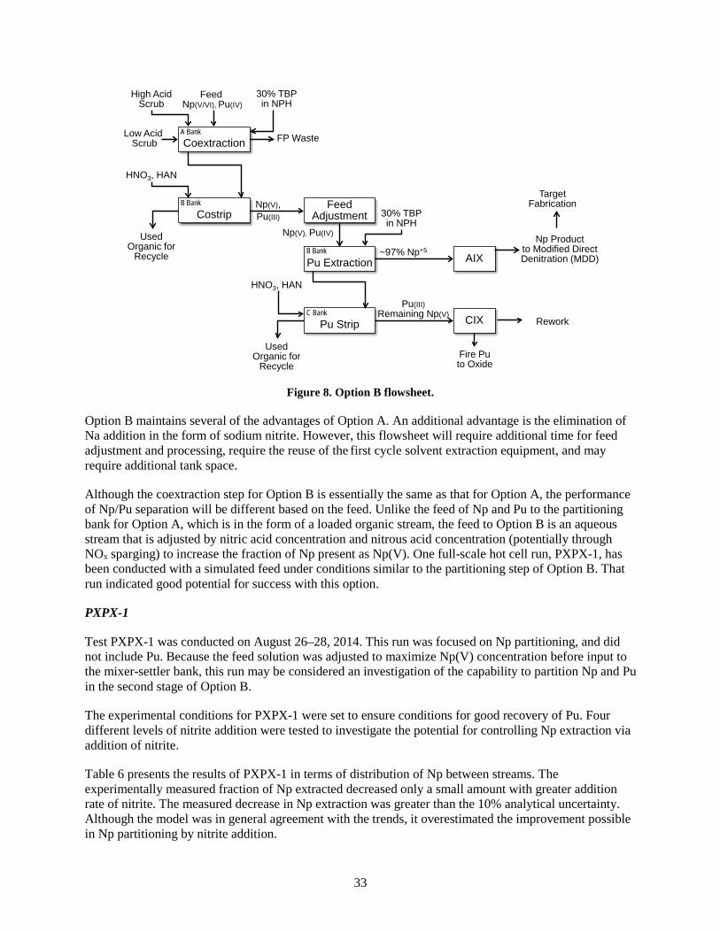
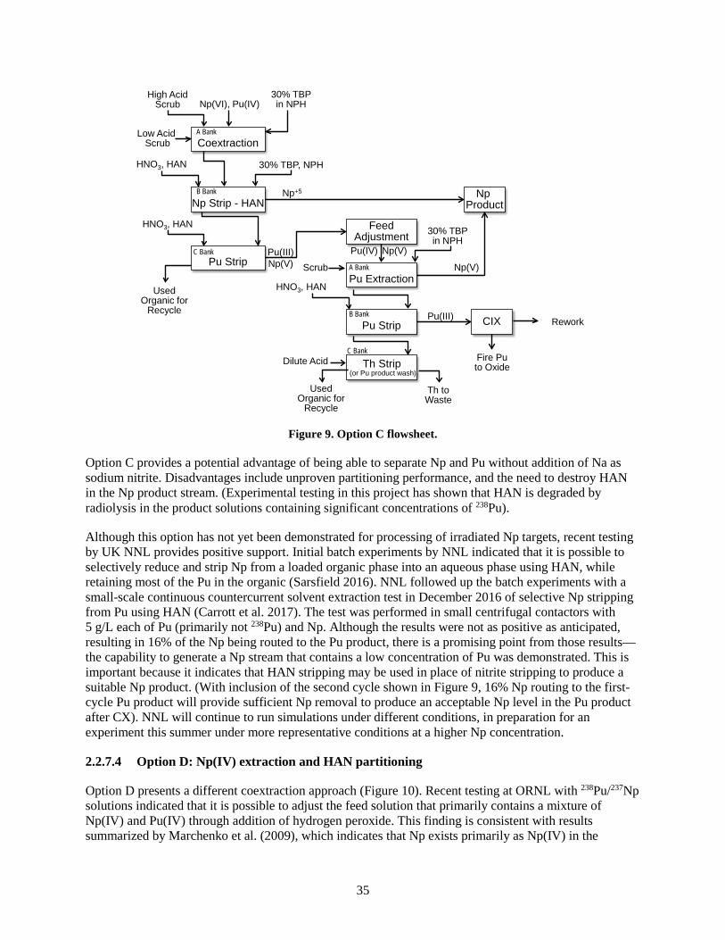
solvent extraction processing. ........................................................................................................ 16 Figure 4. Schematic of Option A. ............................................................................................................... 26 Figure 5. Option A flowsheet. ..................................................................................................................... 26 Figure 6. Predicted effect of feed concentration on Np loss in coextraction bank...................................... 29 Figure 7. Predicted effect of temperature on Np loss in coextraction bank. ............................................... 30 Figure 8. Option B flowsheet. ..................................................................................................................... 33 Figure 9. Option C flowsheet. ..................................................................................................................... 35 Figure 10. Option D flowsheet. ................................................................................................................... 36 Figure 11. Interfacial material collected during phase separation after cleanup of solvent from run
P2PX-1 illustrates some issues with used solvent. ........................................................................ 39 Figure 12. Some difficulties resulting from slow phase disengagement of used solvent were
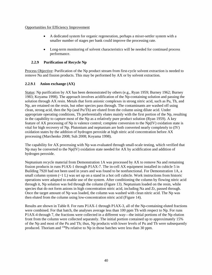
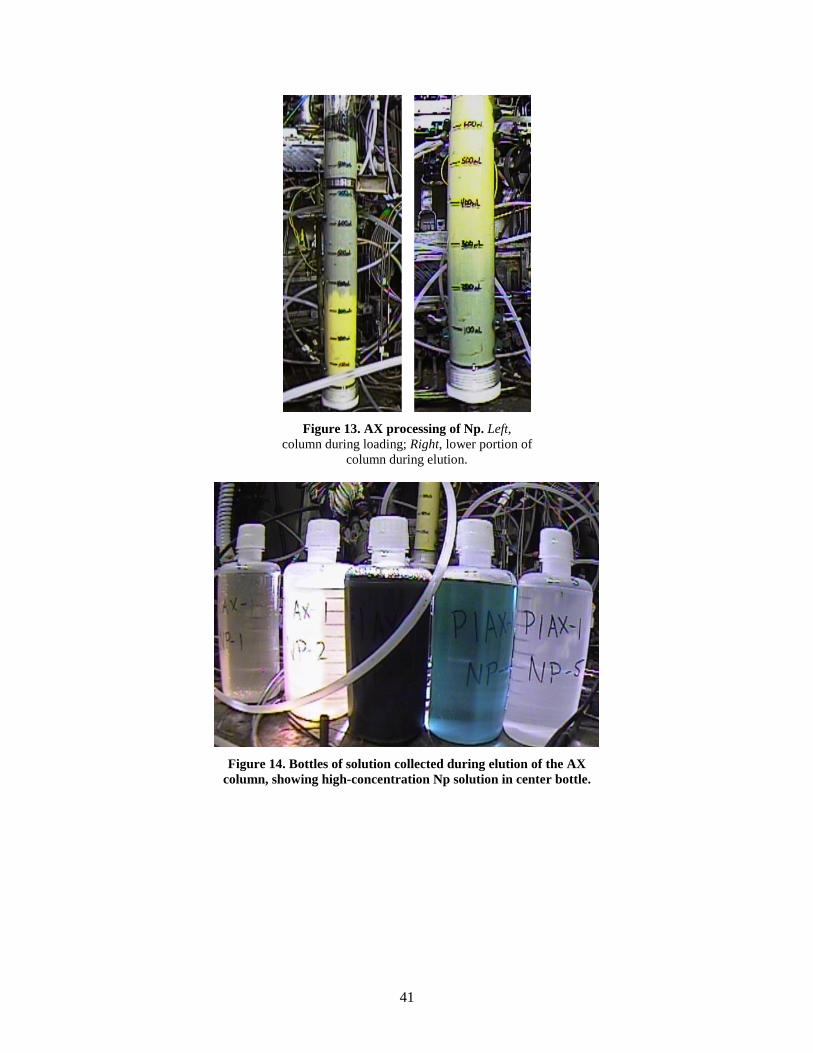
encountered and addressed in run PXPX-3.................................................................................... 39 Figure 13. AX processing of Np. ................................................................................................................ 41 Figure 14. Bottles of solution collected during elution of the AX column, showing high-
concentration Np solution in center bottle. .................................................................................... 41 Figure 15. Schematic of solvent extraction process used for removal of Na from Np solution in
run PXPX-3. ................................................................................................................................... 43 Figure 16. Image of stripping bank during solvent extraction run P2PX-2. ............................................... 43 Figure 17. Progression of images during loading of resin during run P1PO-3. .......................................... 45 Figure 18. Fired resin from run P1PO-3. .................................................................................................... 46 Figure 19. Comparison of nominal and improved operating strategies as process step durations
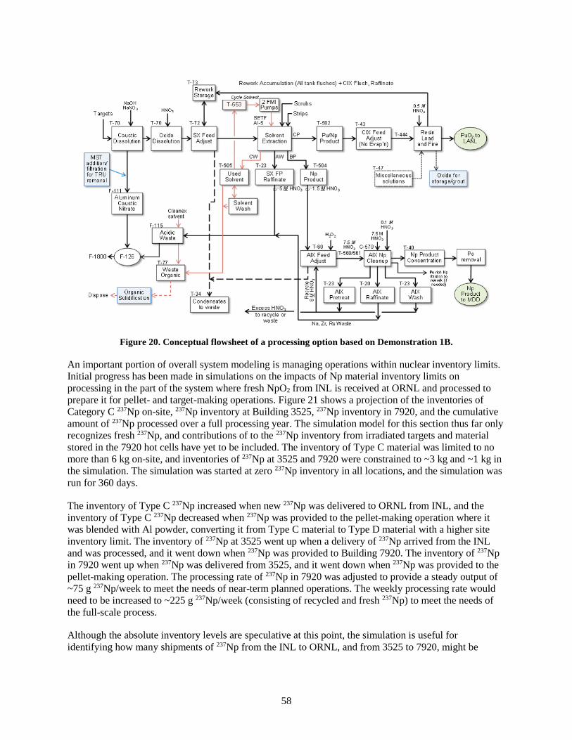
are increased. ................................................................................................................................. 57 Figure 20. Conceptual flowsheet of a processing option based on Demonstration 1B. .............................. 58 Figure 21. Simulated inventory levels of 237Np on-site, at 3525, and 7920 as 237Np from INL is
processed into cermet target pellets. .............................................................................................. 59
LIST OF TABLES
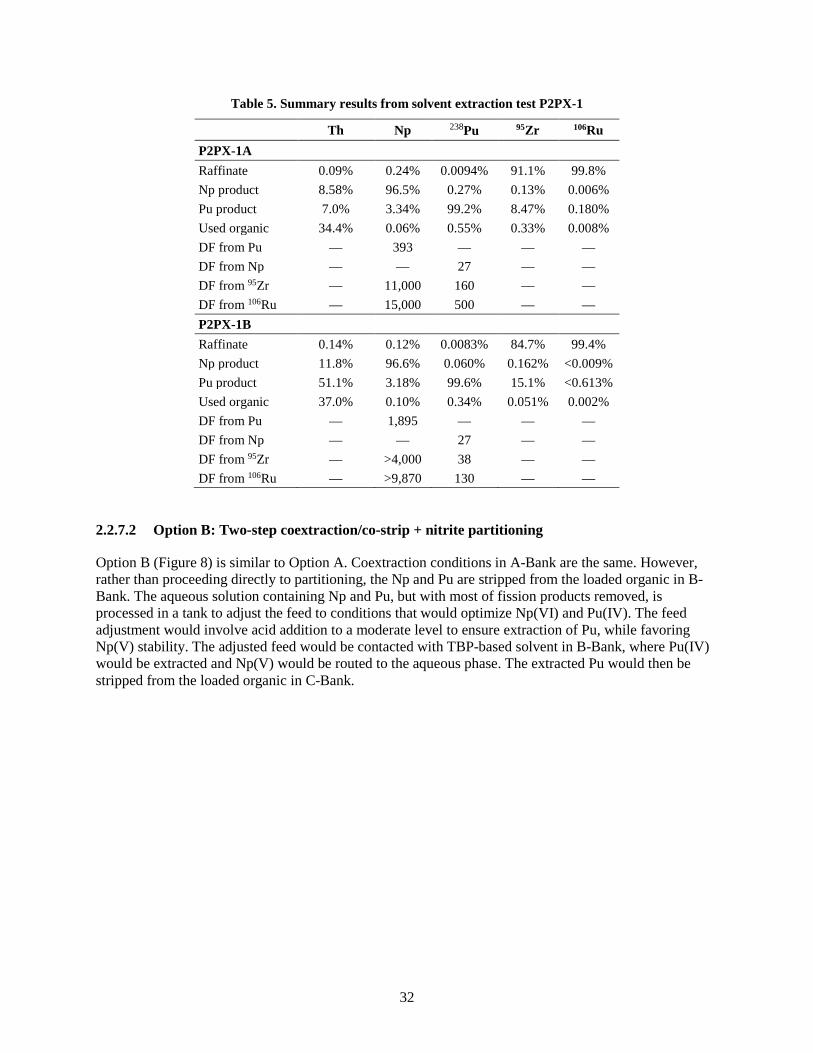
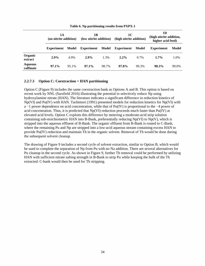
Table 1. State of development in chemical processing steps ........................................................................ 4 Table 2. Summary of results for target dissolutions in Demonstrations 1A and 1B ................................... 22 Table 3. Stream results for PXPX-2............................................................................................................ 28 Table 4. Results of solvent extraction test P1PX-1 ..................................................................................... 30 Table 5. Summary results from solvent extraction test P2PX-1 ................................................................. 32 Table 6. Np partitioning results from PXPX-1 ........................................................................................... 34 Table 7. Summary of solvent extraction options ........................................................................................ 38 Table 8. Results of AX runs in Demonstration 1A ..................................................................................... 42 Table 9. Results of resin firing in Demonstrations 1A and 1B ................................................................... 47 Table 10. LANL and ORNL analyses of PuO2 samples from Demonstration 1A ...................................... 48 Table 11. Elements in preparation for Campaign 3 .................................................................................... 54 Table 12. Proposed Np processing routes ................................................................................................... 55
vii
ACRONYMS
AX anion exchange CH-TRU contact-handled transuranic waste CHON carbon-hydrogen-oxygen-nitrogen compound CX cation exchange DF decontamination factor GPHS General-Purpose Heat Source ICP-MS inductively coupled plasma mass spectrometry HAN hydroxylamine nitrate HDEHP di-(2-ethylhexyl) phosphoric acid HDBP di-n-butyl phosphoric acid HFIR High Flux Isotope Reactor HS-PuO2 heat-source plutonium oxide IHE inhalation hazard equivalent INL Idaho National Laboratory LANL Los Alamos National Laboratory LIBS laser-induced breakdown spectroscopy LLLW liquid low-level waste MDD modified direct denitration MST monosodium titanate NNL National Nuclear Laboratory ORIGEN Oak Ridge Isotope Generation and Depletion code ORNL Oak Ridge National Laboratory PO plutonium oxide, used as label for resin loading and firing step PSP Plutonium Supply Program PUREX Plutonium Uranium Redox Extraction REDC Radiochemical Engineering Development Center SETF Solvent Extraction Test Facility SRS Savannah River Site TBP tri-n-butyl phosphate TRU transuranic UDS undissolved solids USQ Unreviewed Safety Question
viii
ix
FOREWORD
This report presents a high-level summary of the status of development of chemical processes to produce 238Pu from irradiated 237Np targets at the Radiochemical Engineering Development Center at Oak Ridge National Laboratory. The effort described in this document is current through Demonstration 1 of the Plutonium-238 Supply Program as of early May 2017. Development and testing are continuing.
This report provides a description of the chemical processes under development with a relatively low level of technical detail, with no export-controlled information. Other reports will provide greater levels of technical detail.
xi
ACKNOWLEDGMENTS
Progress in the Plutonium-238 Supply Program is made possible through the dedication and hard work of many individuals in multiple organizations. A partial list of contributors who have been instrumental in the progress of chemical process development is given below.
Experimentation and analysis for process development was performed by members of the Nuclear Security and Isotope Technology Division, including Jonathan Burns, Kevin Felker, Chris Jensen, Catherine Mattus, Kristian Myhre, Joanna McFarlane, Clarice Phelps, and Joseph Spahr. Inventory management support was provided by Jon Garrison, Laura Harvey, Riley Hunley, Tom Hylton, Robin Taylor, and Gary West.
The Radiochemical Engineering Development Center Operations of the Oak Ridge National Laboratory Nonreactor Nuclear Facilities Division conducted a large fraction of the work in the hot cells and ensured that the development work in the nuclear facilities was performed in compliance with applicable requirements. In addition to facility and operations managers Porter Bailey, Roger Weaver, and Allen Smith, significant contributors include Mindee Albright, Dan Bettinger, Don Caverly, Fred Chattin, Jason Cook, Cory Dryman, Sergio Dukes, Michael Green, Steven Hinds, Samuel Lawson, Marty Milburn, Charles Nevius, James Parfitt, Gerald Sullivan, Brad Tinker, Matt Walker, and Ken Wilson.
Analytical method development and the processing of many challenging radiochemical samples was conducted by the Nuclear Analytical Chemistry and Isotopics Laboratory of the Oak Ridge National Laboratory Chemical Sciences Division, including Doug Canaan, Jeff Delashmitt, Ben Roach, Jordan Couch, Joseph Guy, Howard Meadows, and Rob Smith.
1
1. SUMMARY
This document summarizes the status of development of chemical processing in the Plutonium-238 Supply Program (PSP) near the end of Demonstration 1. The objective of the PSP is “to develop, demonstrate, and document a production process that meets program objectives and to prepare for its operation” (Frazier et al. 2016). Success in the effort includes establishing capability using the current infrastructure to produce Np targets for irradiation in Department of Energy research reactors, chemically processing the irradiated targets to separate and purify the produced Pu and transferring the PuO2 product to Los Alamos National Laboratory (LANL) at an average rate of 1.5 kg/y.
The location of chemical processing in the overall 238Pu production process is outlined in Figure 1. These steps will be conducted in heavily shielded cells suitable for containment of alpha-emitting isotopes and fission products. Chemical processing is needed to prepare the NpO2 feedstock for target fabrication. This step involves dissolution of the oxide material and treatment for removal of the 233Pa daughter of 237Np. In addition, the dissolved feed material may also be treated for removal of Pu and Th. Protactinium removal is required to reduce radiation dose to workers during steps conducted in shielded glove boxes for conversion of the Np to an oxide powder and subsequent target fabrication. Plutonium removal may be needed for some batches of NpO2 to reduce the 238Pu inventory to stay within facility limits. Thorium must be removed at some point in the process to allow LANL’s product material to meet the General-Purpose Heat Source (GPHS) specification of 0.5 wt%, as each batch of stored NpO2 has elevated Th levels and LANL’s aqueous processing does not have a significant decontamination factor (DF) for Th.
Figure 1. Chemical processing within overall 238Pu production steps.
The bulk of the activities in chemical processing will be performed on the material from irradiated Np targets. The target materials will be dissolved and taken through a series of processing steps to separate the Pu and Np from fission products, separate and purify the recovered Np for recycle for the fabrication
Np Oxide
Target Processing
RecoveryRecycled Np
ORNL REDC
ORNL HFIR/INL ATR
INL
Neptunium Feed Stock
Chemical Processing
Conversion to Oxide Powder
Target Fabrication
Dissolution
Removal of 233Pa
Removal of Pu, Th (as needed)
Shipment to ORNL
TargetIrradiation
LANL
Delivery of New 238Pu to LANL
Chemical Processing
2
of new targets, purify the Pu and convert to oxide of sufficient quality to enable LANL to produce heat source pellets.
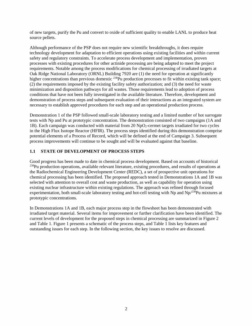
Although performance of the PSP does not require new scientific breakthroughs, it does require technology development for adaptation to efficient operations using existing facilities and within current safety and regulatory constraints. To accelerate process development and implementation, proven processes with existing procedures for other actinide processing are being adapted to meet the project requirements. Notable among the process modifications for chemical processing of irradiated targets at Oak Ridge National Laboratory (ORNL) Building 7920 are (1) the need for operation at significantly higher concentrations than previous domestic 238Pu production processes to fit within existing tank space; (2) the requirements imposed by the existing facility safety authorization; and (3) the need for waste minimization and disposition pathways for all wastes. Those requirements lead to adoption of process conditions that have not been fully investigated in the available literature. Therefore, development and demonstration of process steps and subsequent evaluation of their interactions as an integrated system are necessary to establish approved procedures for each step and an operational production process.
Demonstration 1 of the PSP followed small-scale laboratory testing and a limited number of hot surrogate tests with Np and Pu at prototypic concentration. The demonstration consisted of two campaigns (1A and 1B). Each campaign was conducted with material from 20 NpO2-cermet targets irradiated for two cycles in the High Flux Isotope Reactor (HFIR). The process steps identified during this demonstration comprise potential elements of a Process of Record, which will be defined at the end of Campaign 3. Subsequent process improvements will continue to be sought and will be evaluated against that baseline.
1.1 STATE OF DEVELOPMENT OF PROCESS STEPS
Good progress has been made to date in chemical process development. Based on accounts of historical 238Pu production operations, available relevant literature, existing procedures, and results of operations at the Radiochemical Engineering Development Center (REDC), a set of prospective unit operations for chemical processing has been identified. The proposed approach tested in Demonstrations 1A and 1B was selected with attention to overall cost and waste production, as well as capability for operation using existing nuclear infrastructure within existing regulations. The approach was refined through focused experimentation, both small-scale laboratory testing and hot-cell testing with Np and Np/238Pu mixtures at prototypic concentrations.
In Demonstrations 1A and 1B, each major process step in the flowsheet has been demonstrated with irradiated target material. Several items for improvement or further clarification have been identified. The current levels of development for the proposed steps in chemical processing are summarized in Figure 2 and Table 1. Figure 1 presents a schematic of the process steps, and Table 1 lists key features and outstanding issues for each step. In the following section, the key issues to resolve are discussed.
3
Figure 2. State of development of steps in chemical processing.
Aluminum Dissolution in Caustic Nitrate
Actinide and Fission Product Dissolution in
Nitric Acid
Solvent Extraction
Neptunium Purification Plutonium Purification
Neptunium Conversion to Oxide (Modified Direct Denitration)
Plutonium Conversion to Oxide
Target Fabrication Plutonium Product Shipment
Reject Np Target Material Dissolution
Np Oxide Dissolution Organic Recycle
Waste Disposition
Rework Processing
Hardware Removal from Targets
Irradiated Neptunium Targets
Neptunium Targets for Irradiation
Plutonium Oxide to LANL
Np Pu
Neptunium Oxide from INL
Fission Products
Concept only; not tested to date
Partial progress; significant issues to
address
Positive progress; options identified to
address issues
Demonstrated; scale-up and/or efficiency issues
exist
Satisfactory for full-scale production
State of Development:
UDS processing
Reject Pu oxide processing
4
Table 1. State of development in chemical processing steps
Process Step Level of Development Comments
Np oxide dissolution
Dissolution of Savannah River Site (SRS) NpO2 from Idaho National Laboratory (INL) has been proven at a scale of several hundred grams per batch, which is suitable for full-scale production. Dissolutions have been conducted in glass pots in the hot cell cubicles. For long-term production operations, it is desirable to establish this process in permanently installed equipment with less potential for conflict with other operations.
Dissolution of target fabrication reject material
Dissolution of reject material from target fabrication has not been tested. There is potential for issues because of heat treatment to 1,200°C of the NpO2.
Pa removal Pa removal has been proven in over 25 batches of NpO2. Recent positive demonstration of silica gel in the place of porous glass beads may result in performance improvement at significantly lower material cost.
Purification of dissolved NpO2
A fraction of NpO2 batches from INL will require removal of Th and Pu for improved efficiency. A di-(2-ethylhexyl) phosphoric acid (HDEHP) extraction process has been demonstrated as effective for Pu and Th removal; however, that approach could result in ~2% loss of Np. In addition, the possible carryover of phosphorus-containing species from the HDEHP extraction in the Np solutions is being investigated as a potential cause for high rates of reject cermet pellets for batches using that extraction approach.
Alternative technologies for Th and Pu removal, including AX, cation exchange (CX), and other solvent extraction approaches, are being considered.
Irradiated target dissolution
Irradiated target dissolution has been proven at a scale of 20 targets. An issue with filterability that was experienced during a full-scale test of caustic dissolution with dummy targets has been addressed by implementing the caustic dissolution in two steps. The maximum number of targets that may be dissolved per batch has not yet been determined. Caustic addition amount has not been optimized.
Acid dissolution has been successful in nearly complete dissolution of the Np and Pu in the targets during the first two demonstrations. Dissolution of actinide oxides was essentially complete in 24 h at the 20-target scale. The approach, both in cycle time and in acid addition, has not yet been optimized. Undissolved solids have not yet been characterized or quantified.
5
Table 1. State of development in chemical processing steps (continued)
Process Step Level of Development Comments
First cycle solvent extraction separations
Good progress has been made toward reducing the risk of failure of solvent extraction separations. Coextraction of Np and Pu has been demonstrated at a feed rate suitable for full-scale production. Because Np recovery is dependent on the rate of an oxidation reaction, there appears to be a limit on the rate at which Np may be fed to the system without unacceptable losses of Np.
Partitioning of Np and Pu by stripping Np using nitrite reduction has been demonstrated to produce a Np stream that is sufficiently low in Pu (<50 ppm) and a Pu stream with sufficiently low level of Np for subsequent Pu purification. Nitrite addition results in a high level of sodium in the Np outlet stream, requiring a subsequent removal step, and a significant contribution to waste mass.
Alternatives to Np stripping by nitrite (Option A) have been proposed but not yet tested. One option, Option B, is a two-step solvent extraction process, coextraction/co-strip of Np and Pu, followed by feed adjustment to conditions that favor Np(V) using reagents that do not contribute salt mass waste (e.g., hydroxylamine nitrate [HAN], NO sparging at moderate acid concentration, or both), followed by a Pu-selective extraction/strip. Another option, Option C, involves selective stripping of Np by reduction of Np(VI) to Np(V) using HAN; this option has been advocated by collaborators at National Nuclear Laboratory (NNL), who have conducted initial tests with positive results and will be undertaking more representative flowsheet tests in the upcoming months.
Pu stripping by HAN has been demonstrated. However, the approach used in Demonstration 1A (run P1PX-1) resulted in too high of a concentration of Th in the Pu product. Th removal was improved with a Pu strip using a higher concentration of HAN in Demonstration 1B (P2PX-1); however, Th was not removed sufficiently. A combination of a Pu strip at a lower flow rate using HAN at lower concentration, plus an organic back-scrub, is expected to provide sufficient Th removal and better Pu concentration in the product.
Organic recycle
Organic recycle has not yet been demonstrated in solvent extraction processing of irradiated target solutions. However, recent solvent extraction processing of Np solution has demonstrated solvent cycling within a run. In addition, reuse of solvent from run P2PX-1 has provided evidence that washing used solvent may be successful. This is significant for reducing organic waste volume.
6
Table 1. State of development in chemical processing steps (continued)
Process Step Level of Development Comments
Np purification for recycle
Purification of Np for removal of Na and Zr has been demonstrated by anion exchange (AX). AX runs generate a stream of approximately 85% of the Np with acceptably low levels of Th and Pu, and another cut containing approximately 15% of the Np containing Pu and Th that requires further treatment (the fraction of recycled Np will depend on Th and Pu levels in the feed material). AX treatment has been demonstrated at the scale of a 1 L bed volume column; this scale which can generate ~50–60 g of clean Np and ~5–10 g of Np requiring further cleanup. A column with 3 L bed volume has been fabricated but has not yet been implemented in the hot cell.
Removal of Na by solvent extraction has been successfully demonstrated at a scale of ~25 g/h in runs PXPX-3 and P2PX-2. Those two runs efficiently processed a total of ~1.4 kg of Np. Solvent extraction processing of Np requires approximately 10% of the nitric acid required for AX. However, a remaining issue to investigate is acceptability of Np product for target fabrication, due to potential phosphorus content.
Pu purification
Purification of Pu to acceptable levels of Np and most impurities listed in the GPHS specification has been demonstrated by CX processing. The levels of impurities were corroborated by LANL analysis. Thorium, phosphorous, and zirconium were identified as impurities at elevated levels. The potential for S in the product has not been fully evaluated.
The capability for decontamination by LANL aqueous processing needs to be evaluated to set targets for purification of Pu by ORNL.
If further purification at ORNL is needed, additional development efforts will be required. A potential technology for cleanup of Pu is AX, which could be followed either by cation resin loading and firing, or oxalate precipitation and calcination.
Pu conversion to oxide
Conversion of CX resin loaded with Pu has been demonstrated at a scale of ~10–20 g of Pu per batch, using a resin firing approach that has been utilized for decades. A column and furnace design has been developed for scale-up to a production scale of approximately 75 g per batch. Scale-up issues with insufficiently fired resin encountered using larger columns during Demonstration 1B need to be resolved prior to use of the production-scale column. The larger furnace, which is designed to also be usable by the californium program, is currently scheduled to be installed prior to Campaign 3.
PuO2 packaging and shipment Two shipments to LANL of ~5 g of PuO2 each have been made. Equipment and facility safety documentation must be developed for shipments of larger quantities.
7
Table 1. State of development in chemical processing steps (continued)
Process Step Level of Development Comments
Oxide product quality Good agreement was demonstrated between chemical analyses performed by LANL and ORNL on oxide product generated during Demonstration 1A.
Heat source plutonium oxide (HS-PuO2) generated from Np targets irradiated for two HFIR cycles were measured to have high 238Pu assay (88%) and acceptably low 236Pu level (2 ppm).
Oxide produced during Demonstration 1A had acceptably low levels of actinide impurities, with the exception of Th, which was present at ~0.7–1.1 wt % in the oxide product. The main non-actinide impurity requiring attention is phosphorus. Zirconium-95/niobium-95 content was measured to be higher than that in oxide material typically processed by LANL, but the levels of those short-lived isotopes may be managed by storage.
Waste disposition, near term Waste disposition issues for the near term primarily focus on reducing transuranic (TRU) levels in waste solutions to be disposed through the existing liquid low-level waste (LLLW) system at ORNL. Progress has been made in: demonstration of regeneration and reuse of organic solvent, reduction of TRU levels in aqueous waste by application of Cleanex batch extraction, and capture and solidification of Pu and other materials by resin loading and firing. Testing of monosodium titanate (MST) for removal of TRU from samples of actual caustic waste is planned.
Interactions are ongoing with ORNL waste system planners to address a key issue—disposition of TRU-contaminated waste organics.
Waste disposition, longer term Waste disposition issues for the longer term focus on efficiently producing wastes that may be processed in a new facility to be built at ORNL for radiological waste treatment. In addition to the near-term issues identified above, there will be needed to further reduce waste mass/volume and to treat/segregate streams to enable efficient processing and disposition. Progress has been made in evaluating options to reduce acid usage. Key aspects to be addressed include reduction/elimination of Na nitrite addition, elimination of Al waste mass through use of a different target design, efficient tank usage to reduce flush volumes and cross contamination, and identification of treatment processes to minimize production of remote-handled TRU.
Legend:
1—Concept only; no testing performed. 2—Partial progress; significant issues must be addressed. 3—Positive progress has been made in process development; options being considered to address remaining
issues. 4—Successful demonstration in process development; scale-up or efficiency issues need to be addressed. 5—Satisfactory for full-scale production; process efficiency improvements may be possible.
8
1.2 KEY ISSUES TO RESOLVE
The summary above points to several remaining technical questions related to the proposed process steps. The following issues appear to pose the most immediate need for Campaign 3 and interim operations.
1.2.1 Neptunium Recycling and Cleanup for Target Fabrication
Over the past several months, Np transferred from the hot cells to the labs for target fabrication has come exclusively from dissolved NpO2. This approach was adopted to maintain pellet production to fabricate targets because high pellet rejection rates had been experienced with batches of recycled Np processed with HDEHP for Pu/Th removal. Direct use of dissolved NpO2 (without Pu and Th removal) was possible because the batch of NpO2 currently being processed has sufficiently low (<100 ppm) 238Pu concentration. Other batches have higher levels of 238Pu and may require treatment for Pu removal before target fabrication. Th removal is desired on all batches of NpO2.
To maintain Np inventories at workable levels, processes for Pu and Th removal will need to be proven soon for the following types of solutions:
• Recycle solutions • Dissolved oxide • AX eluent Np fraction with high Np/Pu
A batch solvent extraction approach would be attractive because it could be conducted in small batches outside the hot cell, reducing the overall burden on the hot cells and reducing the potential for contamination of the Np solution. The Pu/Th removal provided by HDEHP extraction is attractive; however, phosphorus content in the Np solution carried over from the extraction is suspected as a contributor to production of reject pellets. In addition, stripping of Np from the HDEHP is not complete under conditions that have been tested, with losses on the order of 2%. Other extractants, including those without phosphorus, may be suitable. In each case, testing must be conducted to prove that the extraction does not increase the rate of reject pellet production. Diluent washing, with improved phase separation, may reduce potential for carryover of contaminants that could affect pellet production. This situation is exacerbated by difficulties in analyzing for phosphorus in solutions with high concentrations of Np or Pu.
Experiments are ongoing to (1) establish an effective method for quantifying phosphorus content in high-concentration Np solutions; (2) evaluate P levels in solutions contacted with HDEHP and tri-n-butyl phosphate (TBP) solvents; and (3) identify approaches for reduction of phosphorus as well as Pu/Th in Np solutions. Recent results toward developing an analytical method to determine the phosphorus content in concentrated Np/Pu solutions have been positive. In-cell testing has demonstrated a detection limit of 1 ppm of phosphorus in Np or Pu, decreasing the previous detection limits by a factor greater than 50 and eliminating the injection of concentrated solutions in the inductively coupled plasma mass spectrometry (ICP-MS) instrument. This sample improvement led to greater plasma instability and a reduction of lengthy flushing of the system. Testing with surrogate solutions has indicated that P contamination in solutions contacted with HDEHP solvent may be reduced by pre-washing the solvent; however, the remaining P-containing compounds are not readily removed by subsequent diluent washing of the aqueous solution. There is lower but significant phosphorus contamination in solutions that have been contacted with TBP, and diluent washing and treatment by AX resin has been shown to be effective in reducing the phosphorus level in the aqueous solution. Conditions for effective removal of Pu/Th by CX treatment have been identified, and current testing of the viability of that approach is focused on determining resin capacity.
9
AX is currently the baseline technology for Np cleanup. It has been proven to generate acceptable Np recycle product for cermet pellet production at low reject rates; however, this approach is less efficient than solvent extraction from both waste generation and production rate standpoints. Because no other acceptable route has been proven, AX processing using a large column will be initiated to clean up the approximately 1.3 kg of recycle Np that remains after Demonstration 1B.
1.2.2 Organic Disposition
Organic disposal will be required for 238Pu production. Despite efforts aimed at reuse of TBP solvent, there will be a waste stream of used solvent that is no longer usable. In addition, because Cleanex extraction has proven to be effective in reducing TRU levels in the combined acidic waste stream from the 7920 hot cells, used organic solvent will continue to be generated from that process.
Organic disposal is an unresolved issue that could negatively affect 238Pu production. Rough estimates indicate that the current tank used for storing used organic (T-77) could approach maximum usable capacity by the end of Campaign 3. Interactions are ongoing with ORNL waste system developers to identify options for organic solidification. The main technical issue is related to generation of a suitable solidified organic waste form with acceptable radionuclide release fraction properties for transfer out of the hot cells within the safety basis of the nuclear facility. Nochar 910 has been identified as a potential solidification agent; however, there is not yet sufficient information on the characteristics of the material to enable evaluation of its uses. Grouting of the organics is also being evaluated the main issue with grouting is the achievable waste loading for acceptable product properties. Recent preliminary testing has yielded promising results for solidification of organics by grouting. Monolithic materials with no free liquids were generated using surrogate organic solutions at loadings above 30 vol%. Testing will continue using organic mixtures that bound anticipated compositions for used TBP-based material from solvent extraction and Cleanex solution used for 238Pu recovery from aqueous waste.
1.2.3 Thorium Removal
Thorium concentration is a key parameter for the product PuO2 because LANL’s aqueous processing does not remove Th from the Pu. Removing Th from the Np before target fabrication is desirable, and experimentation is in progress to develop approaches for Th removal from dissolved NpO2 (Section 1.2.1). However, the targets fabricated to date have elevated Th, as may some future targets. The following options exist for the batches of targets with elevated Np that will be encountered in Campaign 3:
• develop a solvent extraction approach that removes Th to below 0.5 wt%, or
• identify a blend-down plan at LANL to use any ORNL Pu product material having higher Th in conjunction with stored low-Th material to generate acceptable HS-PuO2.
Current planning for Campaign 3 includes a solvent extraction approach to remove Th, so that option is available for future operations. If the test does not work sufficiently well, the blend-down approach may be an option for that limited amount of material.
1.2.4 Effects of Organic Degradation on Solvent Extraction Performance
Organic degradation, primarily from alpha radiolytic and chemical acidolysis damage to the TBP extractant molecules, and the diluent can negatively affect the performance of the solvent in extraction processes (Lloyd and Fellows 1985). Solvent degradation can affect physical properties, eventually leading to difficulties in phase separation in solvent extraction contactors. Also, the production of TBP
10
breakdown products, primarily HDBP, will result in the retention of elements such as Zr, Th, and Pu in untreated organic solvent. Organic solvent cleanup is a well-proven process for exposure to higher levels of fission products, but it is less proven for cases of exposure to 238Pu. Our waste-minimization goal is to adapt the process to this specific case so that new technology does not need to be developed.
Because solvent extraction runs P1PX-1 and P2PX-1 were operated with once-through flow of organic solvent, little information exists on the effects of solvent degradation for this system. Solvent clean up before and after run PXPX-3 indicated that the phase disengagement properties may be improved through solvent washing with carbonate, base, and dilute acid solutions. Campaign 3 will include the first solvent extraction test that will cycle the solvent multiple times through the system during the run.
To guide the selection of conditions for that run and to develop the basis for simple tests that may be run to evaluate solvent quality, a series of small-scale experiments are planned. Solutions characteristic of solvent extraction feed will be contacted with samples of 30% TBP in Exxsol D-60 to load the solvent with Pu. The loaded solvent samples will be aged for varying lengths of time, ranging from the exposure time for a single pass through the solvent extraction system to hours and days. The effect on physical properties and chemistry will be evaluated.
1.2.5 Recycle of Reject Np Materials from Target Fabrication
Reject materials from target fabrication—unusable oxide, reject cermet and NpO2 pellets, and rejected targets—will eventually pose inventory issues. The capability to recycle these materials must be demonstrated. The greatest uncertainty is in the capability to dissolve the NpO2; we do not have sufficient experience in dissolving unirradiated, high-fired NpO2. Small-scale testing is planned for dissolution of unirradiated cermet pellets and segments of unirradiated cermet targets. The caustic dissolution portion of that experimentation will allow measurement of the kinetics of Al dissolution in cermets, which will be helpful in estimating needed digestion time for the second stage of caustic dissolution during target processing. The acid dissolution portion of the test will indicate if the nitric acid dissolution approach that is currently used for irradiated target dissolution will be sufficient. If not, investigation of other approaches will be necessary.
Another item to resolve regarding recycle reject materials is the processing needed for the dissolved Np. It would be convenient if the dissolved material could be routed directly back to target fabrication after Pa removal. However, the results from irradiated target dissolution in Table 1 suggest that a fraction of the Al (on the order a few tenths of a percent to a few percent of the Al) will be present in the Np solution. This Al content, or remaining alloying elements from the Al-6061 cladding, would be detrimental to the modified direct denitration (MDD) process or the properties of the resulting NpO2; therefore, further purification of the Np will be needed. AX or solvent extraction are suitable candidates.
1.2.6 Acceptability of Heat Source PuO2
Following the recommendations of the Preliminary Design Review Board (Frazier et al. 2016), the capability for decontamination of ORNL-produced PuO2 by LANL’s aqueous processing needs to be evaluated to set targets for purification of Pu by ORNL. Resin loading and firing is the preferred option for Pu purification and conversion to oxide because it minimizes the number of process steps. Potential issues affecting the use of resin loading and firing are centered on impurities, including actinides, fission products, and other elements.
Purification of Pu to acceptable levels of Np and most impurities listed in the GPHS specification has been demonstrated by CX processing. The levels of impurities were corroborated by LANL analysis of
11
two samples of PuO2 from Demonstration 1A (Carver et al. 2016). Thorium, phosphorous, and 95Zr were identified as impurities at elevated levels. The potential for S in the product has not been fully evaluated.
ORNL and LANL plan to work cooperatively to identify ORNL product specifications that enable the LANL product to meet GPHS specifications while making overall production as efficient as possible. Newly produced PuO2 will enable continued evaluation and testing at more realistic scale. This issue will not be resolved until after transfer of significant quantities of material to LANL and subsequent processing through aqueous processing and characterization of the product HS-PuO2.
1.2.7 Operability
The US Department of Energy, in conjunction with NASA, has set a desired average yearly production rate of 1.5 kg/y for heat-source PuO2 (HS-PuO2) for the 238Pu supply process now under development at ORNL. Determining the yearly production rate is not straightforward because the 238Pu supply process is a batch process with many overlapping steps, and the overall processing rate cannot be determined simply by summing the durations of the individual processing steps.
Preliminary simulation studies of a conceptual version of a future 238Pu production process have indicated the capability to meet or exceed the production goal of 1.5 kg/y of HS-PuO2 (Thomas et al. 2016, 2017). In those studies, the conceptual process was analyzed using discrete-event system simulation to determine expected production rates, bottlenecks, and the effect of process variability on the production rate. Process alternatives were generated based on lean manufacturing principles, and the alternatives were examined by discrete-event system simulation and compared to the baseline operating sequence to identify better process solutions.
Simulations showed the conceptual process appeared capable of achieving the production goal of 1.5 kg/y of HS-PuO2. However, there is uncertainty in the process from the potential effects of variation. The simulated process failed to reach its production goal when certain operational detractors were introduced in the simulations, but other strategies were shown to enable production capacity of up to 2.3 kg/y of HS-PuO2.
Although those preliminary analyses provide initial validation of the capability of the proposed processes to achieve the production goal, much more needs to be done to plan and evaluate production capability. Details on chemical processing steps need to be updated as the process flowsheet is completed, and the fidelity of the model must be increased. So far, the input data were based on a conceptual process flowsheet with preliminary projections of cycle times for each step, and the only potential non-idealities simulated were increases in chemical process cycle times, regular process disruptions to the target dissolution process, and target losses. Importantly, in the preliminary analyses, no restrictions were placed on nuclear inventory limits, available human resources, storage area or tank capacities, waste restrictions, and other constraints. Those factors are being included in the next step of process integration and analysis, and input data will be updated with information from each target-processing campaign.
12
13
2. DISCUSSION OF CHEMICAL PROCESSING
2.1 APPROACH
Recovery of the needed amounts of 238Pu and 237Np from irradiated Np targets in facilities existing today represents a significant challenge. The radiochemical systems present extreme environments, given the complexity of the chemical systems and the constraints posed by the radiochemical environment. To illustrate the challenge, for targets irradiated for two HFIR cycles, the required DF for Np from Pu to produce an acceptable HS-PuO2 product is approximately 1,650 or greater. A variety of potential approaches could be used to achieve the needed separations; the selection of the approach depends on process scale, available equipment, and facility constraints. We have considered multiple factors in developing the current set of proposed processing steps, including historical production and analyses; installed equipment and current procedures at REDC; and recent literature.
2.1.1.1 Previous 238Pu Production at Savannah River Site (SRS)
When SRS made 238Pu, processing of irradiated targets at SRS was performed in two equipment frames within H Canyon. H Canyon is a large reinforced concrete structure in which chemical processing of highly radioactive materials could be performed remotely without exposing workers to intense radiation fields. This facility historically recovered 235U and 237Np from Al-clad, enriched-uranium fuel tubes from nuclear reactors on-site and other nuclear reactors using liquid chemical processes. It was also the location where irradiated targets containing 238Pu were treated to recover 238Pu for use by NASA. When it was operating, equipment installed in H Canyon was sized to allow for a 238Pu production rate of ~65 kg/y, but was operated, on average, to produce between 12 and 30 kg/y of 238Pu.
The chemical processes used to dissolve irradiated targets and to purify 238Pu at SRS are described in reports that are available in the open literature (e.g., Hill, 1963; Poe et al. 1964; Burney 1983; Groh et al. 2000). In the SRS process, Np targets were dissolved using nitric acid catalyzed with successive additions of mercuric nitrate and potassium fluoride. The dissolved target solution was then subjected to multiple stages of AX. In the first cycle of AX, the Np and Pu were separated from the bulk of the Al, fission products, and other cationic contaminants. The feed was adjusted to 8 M total nitrate with nitric acid, and a combination of ferrous sulfamate and hydrazine were added, with subsequent heating, to adjust Np and Pu species to the (IV) oxidation state. Both Np and Pu were loaded onto AX columns, and after washing with 8 M nitric acid, the Np and Pu were eluted with dilute nitric acid. In the second cycle, the Np and Pu were again adjusted to the (IV) oxidation state in acidified feed and loaded onto AX columns. However, in this step, Pu was preferentially stripped from the resin by washing with 5.5 M nitric acid containing ferrous sulfamate and hydrazine. The Np was then eluted separately with dilute nitric acid. The separated Pu stream could be further purified from iron and sulfur by an additional AX step. Both Np and Pu were recovered from waste streams by means of AX and were recycled along with dissolved targets.
Original process development for Np and Pu at the Hanford Site and SRS were not significantly constrained by waste generation, as each site had large available tank volumes for waste storage. SRS did consider options based on solvent extraction for processing 237Np and 238Pu to replace AX processing (Thompson and Thompson 1977a and 1977b), based the potential that this could reduce cost and waste volume and increase production rate (Groh and Schlea 1970). The authors rightly concluded that the redox reactions that occur with Np and Pu in the (IV) or (VI) oxidation states proceed rapidly enough in 237Np/238Pu mixtures that fractions of those species may not be maintained above the 99.9% target for 24 h after a valence adjustment. Therefore, they considered flowsheets that were dependent on valence adjustment in process. The best performance was obtained using a Np(IV)-Pu(IV) flowsheet that employed MnO2 for feed adjustment and a ferrous sulfamate addition after Pu extraction in the first bank. The losses of Np and Pu were found to be sensitive to the ferrous sulfamate addition point, with opposite
14
trends in losses of Np and Pu with stage location. A test of Np(VI)-Pu(IV) coextraction using nitrite addition was not successful (resulting in 17% and 33% loss of Np); this appears to be caused by the relatively low acidity (1 M) of the feed solution.
2.1.2 ORNL Process Approach
The ORNL process approach has focused on solvent extraction as the primary separation step. Process development has been based on recognition of historic data on Np and 238Pu processing (e.g., Isaacson and Judson 1964; Shulz and Benedict 1972), previous processing at ORNL (e.g., Collins et al. 1982), and previous process evaluations by INL (Todd et al. 2005) and ORNL (e.g., Chemical Technology Division 1999; Wham et al. 2004).
In addition, more recent developments in Np processing were considered; notable among these are works that examined the control of Np oxidation state in nitric acid solutions and in nitric acid–TBP solvent extraction systems (e.g., Precek 2012; Precek et al. 2012; Gregson et al. 2012; Taylor et al. 2013). In particular, the NNL work by Taylor and colleagues indicated the capability to extract Np with low losses in the presence of nitrous acid by adjustment of the nitric acid concentration. However, the more recent studies were focused on Np control using compositions characteristic of used nuclear fuel rather than projected 238Pu production, so those studies were at significantly lower Np concentrations and had a much lower alpha radiation dose, which has a significant effect on the redox state of nitric acid solutions (e.g., Andreichuk 1984).
2.1.2.1 Existing facilities
Plutonium-238 chemical processing is conducted at REDC, a multipurpose radiochemical processing and research facility that includes laboratories, glove boxes, and heavily shielded hot cells. REDC works in concert with the adjacent High Flux Isotope Reactor (HFIR) to accomplish several of its missions. REDC includes personnel with radiochemical processing expertise, along with special equipment and systems to support ORNL’s research and development needs in the production of unique radionuclides for use in research, defense, medical, and industrial applications. Use of this facility in campaign mode with other missions enables the 238Pu production effort to benefit from considerable synergies and distributes a portion of the nuclear infrastructure costs.
The primary facility at ORNL for performing 238Pu chemical processing is Building 7920. Building 7920 is a fully operational facility in which radiochemical materials are studied, processed, purified, and packaged for various customers. It is classified as a Category 2 nuclear facility and equipped with multiple hot labs, radioactive glove boxes, and hot cell facilities. The hot cells are constructed with high-density concrete for shielding, viewing windows made of leaded glass and mineral oil, gamma radiation monitors and alarm systems, and HEPA-filtered ventilation systems. Within Building 7920, a motor-driven intercell conveyor system exists for movement among cells. The facility also includes heavy-duty overhead cranes for the movement of heavily shielded casks, hot cell blocks, and other equipment. One hot cell cubicle is dedicated to analytical activities, and radiochemical laboratories include dedicated radiochemical analyses and isotopic analysis by ICP-MS. The hot cell cubicles are outfitted with fiber optic cables for real-time spectroscopic analyses.
Since construction of Building 7920 was completed in the late 1960s, ORNL has been processing irradiated Cm targets to recover and purify transuranic elements, including Pu, Am, Cm, Bk, Cf, Es, and Fm. Equipment and processes have been installed in the facility’s hot cells to dissolve targets, separate, purify, and precipitate oxides of these elements (e.g., King et al. 1966; King, 1979; Bigelow et al. 1980; Felker et al. 2006).
15
The in-cell process equipment in 7920 was designed to be flexible, and it was designed and built so that it can be maintained or replaced by remote means. The following facility features are relevant to 238Pu processing:
• Target dissolver—This Zr tank (T-70) is mounted in the floor of cubicle 7 so that irradiated targets may be placed into the tank via a covered access port in the top of the tank using manipulators. Dissolution processes have been implemented since the late 1960s, employing dissolution in caustic nitrate for removal of Al, followed by acid dissolution of actinide oxides (Burch et al. 1970; King et al. 1980; Felker 1995).
• Process tanks—Metal tanks in the tank pits are used to contain and store process solutions. All process tanks are jacketed for cooling using a recirculating water system. The process and storage tanks typically vary in capacity from about 20 to 600 L.
• Evaporators—The evaporator tanks are Ta-lined Hastelloy C vessels. The jackets are connected to steam for heating as well as to the recirculating cooling water. Condensates from processing evaporators are routed to a common collection tank (T-34) through a tantalum condensate header.
• Solvent extraction—The Solvent Extraction Test Facility (SETF), located cubicle 5, was designed for hot testing of solvent extraction flowsheets. It includes feed adjustment and feed metering tanks, and three 16-stage mixer-settler contactors (Figure 3). The design offers flexibility in operations; for example, quartz windows allow viewing of the settling stages, and contactors are open on the top for reagent addition and stage sampling. The SETF has been used to evaluate flowsheets for light water reactor spent fuel, Fast Flux Test Facility spent fuel, the Transuranic Elements Extraction, or TRUEX, flowsheet at high activity levels (Collins et al. 1982a, 1982b; Bond et al. 1983; Benker et al. 1986).
• Ion exchange—Facilities and procedures are in place for resin-loading oxide preparation CX. This approach has been used routinely to sorb Am and Cm onto CX resin in a quartz column, which is subsequently calcined to convert the loaded resin to oxide microspheres. The loading-furnace firing operations are performed in cubicle 4. Additional equipment and techniques are available for other ion exchange separations, including AX.
16
Figure 3. Three 16-stage continuous
countercurrent mixer-settlers installed in cubicle 5 used for solvent extraction
processing.
2.1.2.2 Constraints
Chemical processes are under development with consideration of multiple constraints, which include safety requirements, inventory limits, waste limits, and physical constraints imposed by the installed equipment.
Safety
Safety constraints for Building 7920 are defined by the Documented Safety Analysis (Safety Analysis Report for Building 7920, ORNL/7920/SAR). Notable among them are curie limits on the amount of radioactive material in process and storage and limitations on chemical process operations. The curie limits constrain chemical processing operations in several ways, including: (1) materials (e.g., irradiated targets, NpO2) may only be introduced into or taken out of the hot cells when overall inventory allows the transfers; (2) iodine limits impose minimum cooling times before target dissolution; and (3) batch sizes for each process step are limited.
Chemical processes are limited in two ways: (1) explicit limitations on specific processes and (2) strict adherence to processes for approval of operations in the nuclear facility. For process approval, the Unreviewed Safety Question (USQ) process for nuclear and facility safety must be performed to determine whether a proposed change, test, or experiment is a USQ before it is implemented. If a change,
17
test, or experiment is determined to be a USQ, then it must be reviewed and approved by the Department of Energy before it is implemented.
To facilitate process development and implementation, process options that represent minor adaptations of existing approved procedures have been pursued. Although this increases the likelihood for successful implementation of processes within the project schedule, this approach limits the set of chemicals and processes that may be employed and may result in processes that are not optimally efficient. As opportunities for significant efficiency improvement over baseline processes are recognized, the USQ process may be pursued for approval to test alternative processes in the future.
A variety of approved procedures and work plans for actinide processing steps at REDC exist, including dissolution of targets, solvent extraction, loading and firing of CX resin, AX separations, and oxalate precipitation. The approved work plan for mixer-settler operations includes solvent extraction processes using tributyl phosphate (TBP) or di(2-ethylhexyl) phosphoric acid (HDEHP) extractants in a normal paraffin hydrocarbon or mixed paraffinic hydrocarbon (e.g., Exxsol D-60) diluent with nitric acid and/or acetohydroxamic, citric acid, lactic acid, oxalic acid, hydroxylamine nitrate, sodium hydroxide, sodium carbonate, sodium nitrate, and sodium nitrite strip, adjustment, and wash solutions. Existing procedures and work plans for ion exchange processing include Dowex 50W-X8 and Bio-Rad AG MP50 and AG MP-1 resins, with valence adjustment by sparging with NO gas, and/or additions of hydrogen peroxide, sodium nitrite, or hydroxylamine nitrate.
Initial preferences for process development were to use the following for redox control: NO sparging, hydrogen peroxide, sodium nitrite, or hydroxylamine nitrate. Despite its attractive chemical properties for Np/Pu partitioning, hydrazine is avoided because of concerns with hydrazoic acid, and ferrous sulfamate is avoided because of the additional iron mass and potential impacts of sulfate ion. These and other redox reagents may be considered as needed to achieve greater performance or efficiency. However, investigation and deployment of process options with other extractants, resins and/or reagents would require additional review. The extent and time required for review of proposed process changes would be dependent on the potential safety issues posed by the proposed changes.
Inventory Limits
Nuclear Materials Control and Accountability and Nuclear Criticality Safety requirements impose inventory limitations on the amounts of Np- and Pu-containing material that may be stored or in process. These limitations will become increasingly important as the amount of material processed increases. Process efficiency, as well as approaches for accurately accounting for material in storage and in process, projecting future inventories, and planning compliant processing schedules will be necessary to ensure production at desired rates.
Waste
Waste generation plays a significant role in process considerations. Plutonium-238 processing poses a challenge because its high activity (17.3 Ci/g) makes it a primary contributor to TRU waste. The 100 nCi/g threshold for TRU waste corresponds to approximately 6 ppb 238Pu in solution. Liquid waste disposition from REDC is currently governed by the Waste Acceptance Criteria (UCOR, 2016) for LLLW. Liquid radioactive wastes transferred to the LLLW system must not have a total radionuclide activity concentration exceeding 14 Ci/gallon 90Sr equivalent. Solutions containing transuranic isotopes (237Np, 238Pu, 239Pu, 240Pu, 242Pu, 244Pu, 241Am, 242Am, 243Am, 243Cm, 245Cm, 246Cm, 247Cm, 248Cm, 250Cm, 247Bk, 249Cf, and 251Cf) must not have a total specific activity from those nuclides greater than 1,000 nCi/g. Solutions containing most organics, S, P, F, or any Resource Conservation and Recovery Act materials would require review before disposal to LLLW. Beyond the need to stay within those
18
constraints, there is significant incentive to reduce the TRU content of the liquid waste exiting 7920 to levels significantly below the limit to reduce the potential for creation of remote-handled TRU waste that will require treatment in the future.
Physical Constraints
There are many physical constraints imposed by the operations in the hot cells. Most notable are the capacities and materials of construction of process vessels and tanks. Because sections of the process equipment and waste system are constructed of stainless steel or zircaloy, no fluoride may be used, and processes based on nitric acid are selected. The capacities of tanks will limit the batch sizes in processing. This is an important factor for process chemistry, as it constrains the production processes to operate at higher concentrations of Np and Pu than some previous processes. This presents a challenge for these complex radiochemical systems, particularly under conditions for which little information is available in the literature. The limited number and capacities of tanks also presents a challenge in selecting combinations of tank usage and processing schedule to enable desired production with a minimum amount of resource conflicts; activities are in progress to address this issue.
There currently is little free space available for adding new equipment to improve processing efficiency. There are legacy equipment items in the hot cells that are no longer needed but will stay in place because of the considerable effort and expense needed to prepare and discard waste equipment from the hot cells. However, as processing plans become more defined, opportunities for increasing process efficiency will become clearer, and the removal of obsolete equipment may be required to make room for new processing equipment.
2.2 PROCESS ELEMENTS
The elements involved in projected chemical processes are summarized in Figure 2. These steps are discussed in the following sections, which present the objective of each step, a summary of technical status, issues to be resolved, and actions to be undertaken before and during the next campaign to advance process maturity.
2.2.1 Dissolution of NpO2
Process Objective: Neptunium oxide obtained from INL is dissolved to produce feedstock for target fabrication. Using conditions determined through laboratory testing, NpO2 is dissolved in heated nitric acid of moderate concentration.
Status: Dissolution of NpO2 from INL has been proven in the hot cell cubicles at a batch scale of a few hundred grams each, using glass pot vessels. This scale is suitable for full-scale production. The dissolution process is not labor-intensive, and takes approximately 1 day to complete. For long-term production operations, it may be desirable to establish this process in larger batches using permanently installed equipment. However, there are several constraints to consider in developing a long-term option, including potential for contamination of the Np from material in tank from previous operations, limited number of process vessels with appropriate materials of construction, and the need to address Np in the tank heel after transfer.
19
Approach for Campaign 3:
• Neptunium oxide will continue to be dissolved in batches in glass pots in the hot-cell cubicles for the next several months.
• In the future, establishing a NpO2 dissolver/storage tank will be considered.
2.2.2 Protactinium Removal
Process Objective: The 233Pa daughter of 237Np is removed from the Np source solution prior to transfer out of the hot cells. This is performed to reduce the radiation dose to workers during subsequent target fabrication operations.
Status: Approaches for effective Pa removal using columns of porous glass beads were developed in treating over 25 batches of Np. For long-term production operations, it is desirable to establish this process in larger batches using permanently installed equipment. That approach may have less potential for conflict with other operations.
Approach for Campaign 3: Neptunium oxide will continue to be dissolved in batches in glass pots in the hot-cell cubicles for the next several months.
2.2.3 Plutonium/Thorium Removal from Neptunium Solution
Process Objective: The capability to remove Th and Pu from high-concentration Np solutions is needed. Thorium exists at elevated concentrations in most batches of source NpO2. Thorium removal from dissolved NpO2 is therefore desired to remove the contaminant at the front end of the process to increase Np content in targets and to reduce complexity of downstream chemical processing. Plutonium removal is also needed for some batches of dissolved NpO2 to stay within inventory limits, primarily for the target-loading laboratory. Plutonium and thorium removal will also be needed for treatment of other Np solutions, such as the Pu- and Th-rich fraction of Np eluted during AX purification of recycle Np.
For treatment of dissolved NpO2, target values for DFs (defined as ratio of concentrations of Pu or Th to Np in the starting solution divided by that in the ending solution) are approximately 2.5 for Pu and approximately 21 for Th.
Status: Plutonium/thorium removal from high-concentration Np solutions has been demonstrated by single-stage HDEHP extraction. For example, in treatment of dissolved NpO2 in batch NPNC-1, the measured DFs were ~20 for Pu and ~230 for Th. However, there are several negative issues with this approach. The first is sensitivity to Np oxidation state; if Np is not fully converted to Np(V), loss of Np to the solvent may be significant, and the removal of Th is impacted. In run NPNC-1, approximately 4% of the Np was extracted. Efforts to recover the Np from the HDEHP were partially successful, resulting in approximately 2% of the Np from the original solution still in the organic phase after three strips.
Stripping of Np from the HDEHP in other cases was also not complete, with losses on the order of 2% to the waste organic under conditions that have been tested. Another major potential impact is the effect of P-containing compounds in downstream Np pellet production. The rate of production of reject cermet pellets increased from less than 10% to 24% and then to 34% in two batches of Np solution treated with HDEHP. Further testing will be needed to reconsider a solvent extraction approach for Pu and Th removal from Np solutions.
20
Current studies are focused on utilizing CX treatment of Np solutions. In this approach, the Np solution is adjusted to a moderate acidity (from 0.5 to 1.0 M nitric acid), and the Np is converted to the Np(V) oxidation state by addition of a reductant. Under these conditions, Pu and Th are preferentially retained on CX resin, while the Np(V) passes through the column. Results of small-scale testing indicate that excellent Pu and Th removal may be obtained using Dowex 50 resin under conditions where the Np(IV) and Np(VI) concentrations are minimized and the overall Np concentration is not too high.
Approach for Campaign 3: A feasibility test of the CX approach using a larger amount of Np (~60 g) and a larger column bed volume (35 mL) is planned to determine resin capacity for treating dissolved NpO2 solution for Pu/Th removal. Information from that breakthrough test will identify conditions for Pu/Th treatment on batches of dissolved Np batches and Pu/Th-rich recycle Np fractions.
2.2.4 Pre-dissolution Hardware Removal from Targets
Process Objective: In this step, the hardware is cut off the ends of irradiated targets to remove any stainless-steel parts from the target and to reduce the amount of Al that must be dissolved to access the pellets within the target.
Status: A functional approach for shearing ends from the targets exists; however, improvement is needed. The initial efforts in Demonstration 1A were conducted with a manual shear and using targets with multiple end designs. In Demonstration 1B, a refurbished manual shear was used on targets with improved designs, having more clearly marked locations for cuts. Although the current approach is functional, use of the manual shear is time consuming, requires significant operator effort, and contributes to an increased need for manipulator maintenance.
Approach for Campaign 3:
• A prototype of an electrically actuated hydraulic shear has been fabricated and will be tested.
• Standard target designs are being implemented with clearly marked cut locations.
2.2.5 Aluminum Dissolution of Irradiated Targets
Process Objective: Dissolve the Al target structure, and dissolve the Al in the pellet matrix so that the NpO2/PuO2 material in the target can be dissolved in a later chemical step. Sheared targets are placed in a dissolver tank along with a sodium nitrate solution. Sodium hydroxide is metered into the dissolver vessel to control the rate of reaction. After dissolution is complete, the solution is drawn out of the dissolver through a filter and sent to a waste tank. The process used is an adaptation of existing procedures that have been used at REDC for decades.
Status: This step has been tested successfully using a limited number of cermet targets (20% NpO2 design) irradiated for two cycles in HFIR. Work instructions adapted from existing REDC procedures have been generated and revised. Based on laboratory investigations conducted to identify approaches to improve the filterability of solutions, a two-step caustic dissolution approach was developed. In the first step, the Al-6061 alloy clad is dissolved relatively rapidly. After a short period, the caustic solution is cooled and drawn off through a filter to avoid the generation/conversion of hard-to-filter solids. The remainder of the Al in the pellets is dissolved in a second step with a new solution containing additional caustic. The two-step approach was proven at scale of up to 20 full-length targets in the T-70 Dissolving Tank during Demonstration 1A with satisfactory filtration rates. An opportunity to improve efficiency of the operation by sparging of the tank contents during the second caustic dissolution step was incorporated into the work instructions for the Demonstration 1A dissolution (P2DS-1).
21
Table 2 presents material balances for the dissolution steps in Demonstrations 1A and 1B, which are derived from analyses of solution samples. In the table, the rows for cladding are associated with the first caustic dissolution step, and the rows for pellets are for the second caustic dissolution step. For each batch, the data are presented in the top section in terms of total mass (and comparison to amounts predicted by Oak Ridge Isotope Generation and Depletion [ORIGEN] calculations for the target irradiations), and the bottom section presents the distribution of each item among the outlet streams. The results indicate relatively low loss of both Pu (~0.1%–0.15%) and Np (~0.4%–0.5%) in the combined caustic waste stream. The caustic waste stream contained a significant fraction of the Cs (40%–50%) from the irradiated targets, with smaller fractions of the other measured fission products.
Issues/Questions to be Resolved:
• Determine maximum number of production targets that can be dissolved successfully based on measured data and operational experience. An upper limit on the number of targets that may be dissolved with satisfactory filtration rate using current equipment is not yet known. The successful operations with 20 targets is approximately 2/3 scale of that needed in an operating approach using two dissolutions per 63-target campaign.
• Need better estimates of process execution time and batch sizes so that better estimates of process throughput can be determined.
• Need to better characterize the waste generated by the process and how it will be handled during regular production.
• The TRU content of the filtered caustic waste solution is roughly two orders of magnitude greater than limits for TRU waste. Microfiltration of the caustic using 0.5 µm filters yielded minimal reduction in Pu concentration.
Approach for Campaign 3:
• Perform dissolution of targets at a prototypic scale; that is, dissolve the 63 targets in two dissolutions of 31 and 32 targets per batch.
• Perform a test of the use of monosodium titanate (Hobbs 2013, Peters et al. 2011) for removal of TRU from the caustic waste solution.
22
Table 2. Summary of results for target dissolutions in Demonstrations 1A and 1B
Distribution of recovered material Np 238Pu 95Zr 106Ru 137Cs Al Al cladding (%) 0.42 0.11 1.62 4.99 38.01 88.94 Al pellet (%) 0.12 0.04 0.08 5.62 4.27 5.50 Oxide (%) 99.46 99.71 97.83 84.79 57.66 5.56 Condensate (%) — 0.09 0.00 4.05 0.03 — UDS leach (%) — 0.04 0.47 0.55 0.05 —
Note: UDS = Undissolved solids
Opportunity for Efficiency Improvement
It is possible to reduce the amount of sodium hydroxide added and waste mass generated. Caustic dissolutions for Demonstrations 1A and 1B were conducted applying time-tested recipes for target dissolution. The results of Table 2 indicate the amount of caustic used exceeds the amount needed to dissolve the Al in the targets. The overall amount of sodium hydroxide added could be reduced. However, the potential impacts on cycle time and on Al dissolution efficiency in this step and subsequent actinide dissolutions are unknown.
2.2.6 Nitric Acid Dissolution of Irradiated Pellets
Process Objective: Dissolve NpO2 and PuO2 from target pellets in nitric acid so that 238Pu can be purified and recovered, 237Np can be purified and recycled, and fission products and other impurities can be disposed.
Status: The process utilized is an adaptation of existing procedures that have been used at REDC for decades. This process was conducted successfully to dissolve HFIR-irradiated targets that were irradiated for two irradiation cycles in Demonstration 1A (18 targets) and 1B (20 targets). Capability for sparging the solution during dissolution to improve contacting of the solids with the acid was added to the work instructions for Demonstration 1B (P2DS-1).
The overall material balances for the two irradiated target dissolutions are presented in Table 2. The amounts and overall fractions of each element in the acid stream are given in the rows labeled “oxide”. Good recovery of the Pu and Np from the irradiated targets was measured and the measured masses
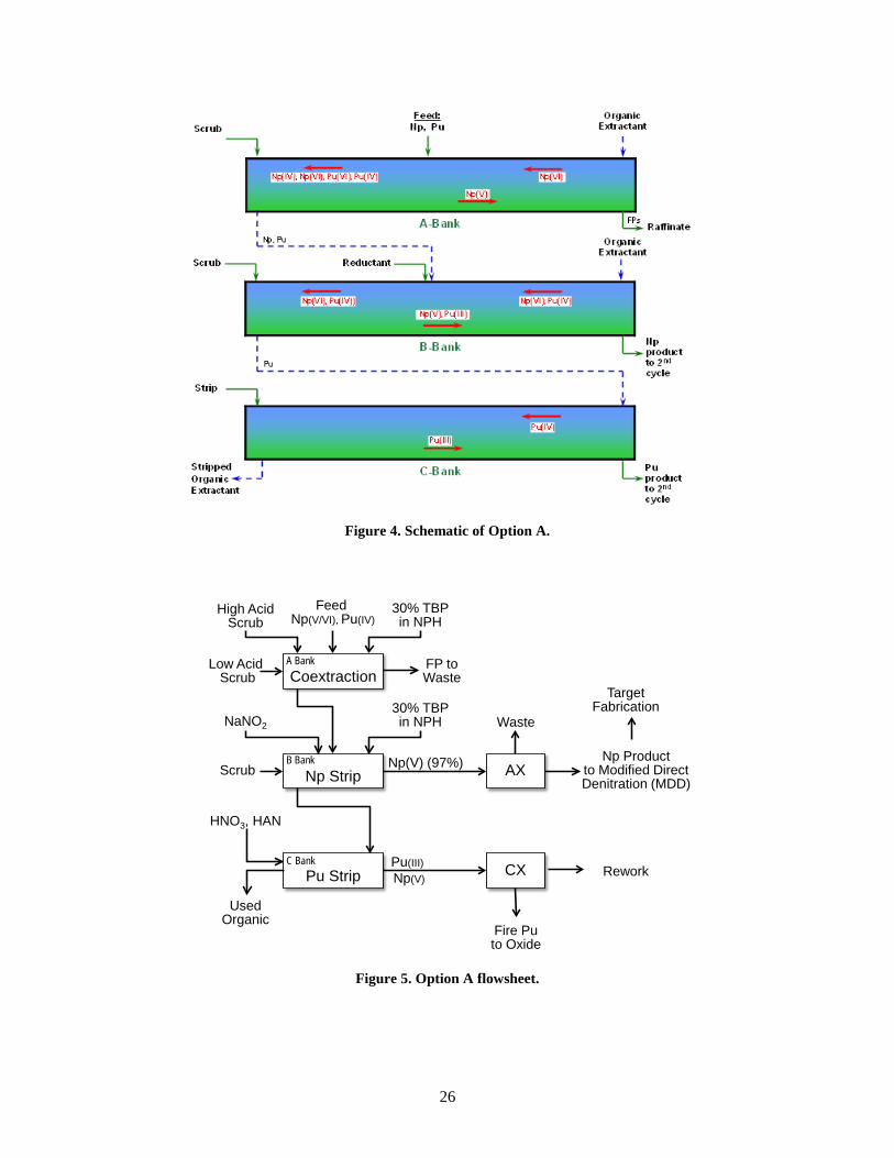
24
(~95% of predicted for Np and ~96–104% of predicted for Pu) fall within the combined uncertainty in the ORIGEN calculations and the analyses of the solutions. The fractions of Np and Pu in the acid stream compared with all streams are consistent, at approximately 99.5% of the measured Np and 99.7% of the measured Pu in the acid stream. Relatively small fractions of the total Pu (0.04%, 0.14%) were measured in solutions obtained from acid digestion of undissolved solids (UDS). Although the UDS has not been quantified or characterized, observations from Demonstrations 1A and 1B indicate there was not a large mass of remaining material.
Issues/Questions to be Resolved:
• Optimize process parameters, including volume and concentration of nitric acid to be used per batch, as well as digestion time at elevated temperature. The goal is to reduce the amount of time for dissolution as well as for feed adjustment prior to solvent extraction.
• Determine a better estimate of processing time required, to support integrated process modeling activities.
Campaign 3 Activities:
Small-scale testing with unirradiated Np target segments are planned. Those tests will provide information on dissolution rates of NpO2 particles, which may be useful for defining cycle time for acid digestion and estimating UDS.
Adjust dissolution parameters for Campaign 3 to improve performance (e.g., length of time and temperature for each step, adjustments to the volume, and concentration of acid used).
2.2.7 Solvent Extraction to Separate Np, Pu, and Fission Product Streams
Process Objective: Solvent extraction is used to provide the primary separation, processing the dissolved target solution into three aqueous streams: a 237Np stream for further purification and recycle, a 238Pu stream for further purification and conversion to oxide product, and a waste stream containing fission products and other impurities.
Four solvent extraction flowsheet options are being considered for first-cycle separations in 238Pu processing and are discussed in the following sections. Each option has potential advantages to enhance processing; however, only one option (Option A) has been tested to date. Solvent extraction separations utilizing TBP extractant are currently pursued. These separations are based on differences in extractability of actinides in various oxidation states. For TBP, the relative extraction of the oxidation states is:
Pu(IV)>Pu(VI)>>Pu(III) Np(VI)>Np(IV)>>Np(V)
One major advantage of TBP-based flowsheets is a good basis of understanding of Pu(IV) and nitric acid extraction from decades of development for fuel reprocessing. That knowledge is accessible for predictive modeling using the SEPHIS computational tool (e.g., Groenier, 1991).
Candidate systems may employ a coextraction step for recovery of Np and Pu and rejection of fission products, followed by partitioning of Np and Pu. The coextraction systems are similar to SETF Campaigns 3 and 4 (Collins et al. 1982), except at higher nitric acid concentration. Consideration of coextraction conditions is based on recent success reported by Taylor et al. (2013). Systems employing
25
nitrite partitioning are considered, similar to those initially investigated by Savannah River (Poe et al. 1964) and reviewed by Shultz and Benedict (1972). Other alternatives under consideration employ hydroxylamine nitrate for Pu/Np partitioning, either by Np(V)/Pu(IV) or Np(IV)/Pu(III) selective extraction.
Although there are many similarities to previously reported studies, there are some significant differences in the projected processes that necessitated developmental testing, primarily no uranium, much higher concentrations of Np and Pu, and a considerably higher alpha dose from the high content of 238Pu. In addition, at the beginning of these tests, no existing domestic solvent extraction model satisfactorily address Np redox state in relevant systems. Model development is underway and significant progress has been made toward predicting Np extraction in these systems.
The solvent extraction option that was used for Demonstrations 1A and 1B is shown schematically in Figure 4 and as part of a flowsheet in Figure 5. This option involves three banks of countercurrent extraction. The first bank is used for extraction of Np and Pu into the organic phase, with rejection of the majority of fission products into the aqueous raffinate stream. The feed is introduced near the center of the bank. The extraction stages to the right of the feed stage enable recovery of Pu and Np, provided there are sufficient residence time and stages for Np(V) oxidation and Np(VI) extraction. The loaded organic from coextraction is routed to the middle of the B-Bank for partial partitioning of Np and Pu. Reductant, in the form of a concentrated sodium nitrite solution, is metered into the feed stage. The extraction stages to the right of the feed stage enable recovery of Pu, whereas the strip stages to the left of the feed stage provide sufficient residence time and contact with extracted nitrous acid for reduction of Np(VI) and stripping of Np(V). The aqueous effluent of B-Bank is the Np product from the first cycle, and it contains a low concentration of Pu but a significant amount of Na and Zr. The Pu-laden organic effluent from B-Bank is routed to the right side of C-Bank and stripped with a low-acid solution containing hydroxylamine nitrate. The aqueous effluent of C-Bank is the Pu product from the first cycle and contains the vast majority of the Pu fed to the system and a small fraction (~3%) of the Np.
26
Figure 4. Schematic of Option A.
Figure 5. Option A flowsheet.
Coextraction
Np Strip
Pu Strip
AX
CX
High AcidScrub
30% TBPin NPH
Low Acid Scrub
NaNO2
30% TBPin NPH
Scrub
HNO3, HAN
UsedOrganic
Waste
Fire Puto Oxide
Np Productto Modified Direct Denitration (MDD)
A Bank
B Bank
C Bank
FP toWaste
Np(V) (97%)
Target Fabrication
Rework
Feed Np(V/VI), Pu(IV)
Pu(III)Np(V)
27
The use of a nitrite addition for control of Np oxidation state maintains Pu primarily in the Pu(IV) oxidation state over a reasonable range of nitric acid concentrations and is compatible with the expected generation of nitrous acid from radiolysis of nitric acid. High-yield coextraction of Np(VI) and Pu(IV) using elevated acid and temperature and a nitrite addition was previously demonstrated by Taylor et al. (2013), albeit at significantly lower Np concentration.
A potential disadvantage of flowsheet A as shown is the addition of sodium to the partition bank. This Na must be removed from the aqueous Np product stream before recycle, and adds to the mass of radioactive waste generated by the process. It may be possible to introduce nitrite to the organic fed to B-Bank via contacting equipment external to the mixer-settlers, avoiding Na addition to the Np product. This option would require additional equipment and testing.
Option A has been tested experimentally in the following three runs:
• PXPX-2—An experiment conducted in December 2014 with a simulated feed containing Np and Pu, but tracer levels of fission products.
• P1PX-1—The first solvent extraction test conducted in October 2015 with material from irradiated targets as part of Demonstration 1A.
• P2PX-1—The second solvent extraction test conducted in June 2016 with material from irradiated targets as part of Demonstration 1B.
PXPX-2
Test PXPX-2 was conducted on December 4–5, 2014. This run was focused on (1) demonstrating Np and Pu coextraction based on results of Taylor and coworkers (2013), and (2) partitioning Np and Pu via nitrite addition. The Np and 238Pu were at prototypic concentrations in the feed. Although the run was intended to be conducted under a single set of conditions, the rate of nitrite addition to B-Bank was inadvertently reduced during the second portion of the run. Consequently, results exist for two different levels of nitrite addition.
Stream results for test PXPX-2 are presented in Table 3. There was excellent recovery of Np and Pu in the coextraction bank, with approximately 0.02% of the Np and 0.006% of the Pu lost to the raffinate stream. Tracer-level fission product results indicated the capability for good decontamination of all fission products except Zr. Only about half of the Zr was extracted in the A-Bank and routed to the aqueous Np product from B-Bank.
The presence of nitrous acid in the nitric acid solution affects the relative amounts of Np(V) and Np(VI) The addition of nitrous acid shifts the system toward reduction of Np(VI), whereas oxidation of Np(V) generates nitrous acid. The results of PXPX-2 indicated that partitioning of Np and Pu is inadequate with insufficient nitrite addition. With the feed of nitrite solution at approximately 1/10th of the design value, the rate and extent of reduction of Np(VI) in the organic was decreased, resulting in conditions that separated only approximately 40% of the Np from the Pu. Partitioning of Np and Pu was improved by the intended level of nitrite addition. Under those conditions, only approximately 3% of the Np was routed to the Pu product. In each of the cases, the level of Pu in the Np product stream was very good, less than 50 ppm.
Most fission products were routed to the coextraction raffinate, with the exception of Zr. Zirconium was distributed among streams and approximately 47% rejected to the raffinate and the majority of the remainder reporting to the Np product.
The results indicate that Pu was extracted well in A-Bank under the conditions. In addition, the selected conditions of acidity, flow rate/residence time, temperature, and feed concentration were sufficient to enable nearly complete oxidation of the Np(V) present in the feed stream to Np(VI) for acceptable extraction of Np in the coextraction bank. There is qualitatively good agreement between the model and experimental results, indicating the model provides a reasonable basis for selection of test conditions. Comparison of the low-nitrite and high-nitrite cases for the partitioning bank illustrates the effectiveness of the nitrite addition in reducing the levels of Np in the organic in the stripping section.
P1PX-1
Solvent extraction test P1PX-1 was conducted on October 28, 2015, using a feed solution generated from the dissolution of 20+ irradiated NpO2 cermet targets. A feed solution was fed near the center of A-Bank. Extraction stages enabled recovery of Pu and provided sufficient residence time for oxidation of Np(V) to extractable Np(VI). The scrub section was divided into low-acid stages for rejection of Zr and high-acid stages for rejection of the majority of fission products. A step taken to attempt to reduce Zr extraction was the addition of 0.8 M oxalic acid to make the feed tank contents 0.025 M oxalic acid because small-scale testing with simulated and real feed solutions indicated a significant reduction in extraction of Zr but no discernable effect on Pu at that level. The loaded organic stream from A-Bank was routed to the middle of B-Bank. A concentrated sodium nitrite solution, was introduced to B-Bank to drive the reduction of Np(VI) to Np(V) for stripping Np from the organic phase. A moderate-acid strip solution is used to shift the equilibrium for Np toward Np(V), and the extracted nitrous acid present in the organic phase provides
29
reactant to continue to act on the Np(VI) as the organic proceeds to stage 1. The Pu and Np present in the organic exiting the partition bank were stripped using a low-acid HAN solution in C-Bank.
The conditions for P1PX-1 were selected based on experience on fission product rejection obtained in previous testing (Benker et al. 1986; Bond et al. 1983), along with insight gained from simulations on control of Np. The recovery of Np in the coextraction bank is primarily dependent on the full conversion of Np(V) to Np(VI), along with the extraction of Np(VI). Likewise, the partitioning of Np is dependent on the reduction of Np(VI) under conditions that enable the essentially complete extraction of Pu.
The kinetics of Np redox reactions places limits on the throughput that is achievable using the SETF mixer-settlers. Several simulations were conducted to explore the effect of relevant variables, including overall flow rate (affecting residence time per stage), temperature, concentrations of components in the feed, locations of inlet streams, and phase ratios. Figure 6 illustrates the throughput limitation in terms of the projected loss of Np with variation of the feed concentration, while holding all other variables constant. Predicted Np loss to the raffinate stream is relatively constant at a low value for low feed concentrations. As feed concentration is increased above a certain level, the loss of Np increases. This may be understood as the system being overloaded with Np(V) at higher concentrations; the oxidation kinetics are not sufficient to completely convert all the Np(V) to Np(VI) at the given conditions.
Figure 6. Predicted effect of feed concentration on Np loss in
coextraction bank.
The potential effect of temperature is illustrated in Figure 7 for three different levels of feed concentration. For lower Np concentration levels, an increase in temperature leads to faster Np(V) oxidation and lower Np losses to the raffinate. However, as the Np concentration is increased, the variation with temperature is not simple. Neptunium loss decreases with increased temperature up to a point, above which Np loss increases with increasing temperature. This may be caused by multiple mechanisms, including an increase in Np(VI) reduction kinetics and reduced Np(VI) distribution coefficient at higher temperatures. The simulations suggest that there will be limits on the throughput achievable and the capability to employ elevated process temperature to improve Np recovery. Although there are significant uncertainties in the model used for the simulations (most notably, Np oxidation/reduction kinetics at higher nitrous acid concentration and at lower nitric acid concentrations), the simulations have provided some valuable guidance toward the selection of conditions for solvent extraction testing.
Relative Np concentration in feed
30
Figure 7. Predicted effect of temperature on Np loss in
coextraction bank.
Results of test P1PX-1 are summarized in Table 4. The loss of Pu and Np to the raffinate from coextraction was good, with approximately 0.004% loss of Pu and 0.12% loss of Np. Approximately 96% of the Np was routed to the Np product stream. That Np product contained an acceptably low level of Pu—26 ppm relative to Np. This represents an overall DF of Pu from Np of approximately 4,000. Approximately 4% of the Np was routed to the Pu strip bank, and the Pu:Np ratio of approximately 4 in the Pu product stream. This represents an overall DF of Np from Pu of approximately 40.
The majority of fission products were routed to the coextraction raffinate, with the exception of Zr. Zirconium was distributed among streams, with approximately 54% rejected to coextraction raffinate, 40% reporting to the Np product, and a relatively small amount in the Pu product. The reason for the partitioning of Zr is not clear. It may be possible that the Zr was converted to multiple forms in feed adjustment steps. The recovery of Zr was low, with only approximately 20% of the 95Zr measured in the feed accounted for in the stream samples. It appears that much of the Zr may have been formed into solids with the combination of oxalate addition to the feed tank, and those solids may not have been delivered into the solvent extraction process.
T0 T0+10°C T0+20°C
Temperature
Relative Np feed rate
31
P2PX-1
Solvent extraction test P2PX-1 was conducted on June 28–29, 2016, using a feed solution generated from the dissolution of 20 irradiated NpO2 cermet targets. These conditions are similar to those of P1PX-1 but with the following changes:
• Two sets of conditions were tested for the coextraction bank to observe the effect of addition of oxalic acid in the scrub solution to reduce extraction of Zr. In P2PX-1A, oxalate was included in the scrub solution, whereas oxalate was not included in P2PX-1B.
• Two sets of conditions were run for the Np/Pu partition bank. In P2PX-1B, conditions were similar to those of the high-nitrite conditions from the previous test, P1PX-1. In P2PX-1A, the acidity and flow rate of the scrub solution were reduced from the previous run. This combination was tested as a means of potentially improving the reduction of Np(VI) by lowering the nitric acid concentration, while maintaining good Pu extraction with the reduced aqueous rate.
• Conditions for the Pu strip bank were adjusted to attempt to improve the separation of Th from the Pu and to concentrate the Pu in the product. The HAN concentration was increased to increase the nitrate concentration in the aqueous phase, and the strip rate was reduced. During the run, it was apparent that the stripping was not proceeding well; in response, the HAN concentration in the CX solution was reduced, and the flow rate was increased.
The results in Table 5 indicate mixed success in run P2PX-1. The coextraction bank operated very well, with excellent recovery of Np and Pu, and good rejection of the majority of fission products. There appears to have been some positive impact of oxalate addition in P2PX-1A for routing of Zr to the A-Bank raffinate, but the overall effect was not large. It appears that the approach used in P1PX-1 with addition of oxalate to the feed tank may be more effective, particularly if combined with filtration of the feed. Conditions tested in P2PX-1A for improved Pu/Np partitioning do not appear to have had a large positive effect. However, these results may have been affected by a period of maloperation during the early portion of the run where the mixer-settlers were not running well in terms of hydrodynamics. Thorium removal was not greatly improved through the tested approach of higher HAN concentration in the strip solution. There appears to be multiple contributing issues that are not well addressed by current solvent extraction modeling tools, including the extraction of Pu(III) at elevated nitrate concentrations and the interaction of nitrous acid with HAN.
32
Table 5. Summary results from solvent extraction test P2PX-1 Th Np 238Pu 95Zr 106Ru
P2PX-1A Raffinate 0.09% 0.24% 0.0094% 91.1% 99.8% Np product 8.58% 96.5% 0.27% 0.13% 0.006% Pu product 7.0% 3.34% 99.2% 8.47% 0.180% Used organic 34.4% 0.06% 0.55% 0.33% 0.008% DF from Pu — 393 — — — DF from Np — — 27 — — DF from 95Zr — 11,000 160 — — DF from 106Ru — 15,000 500 — — P2PX-1B Raffinate 0.14% 0.12% 0.0083% 84.7% 99.4% Np product 11.8% 96.6% 0.060% 0.162% <0.009% Pu product 51.1% 3.18% 99.6% 15.1% <0.613% Used organic 37.0% 0.10% 0.34% 0.051% 0.002% DF from Pu — 1,895 — — — DF from Np — — 27 — — DF from 95Zr — >4,000 38 — — DF from 106Ru — >9,870 130 — —
Option B (Figure 8) is similar to Option A. Coextraction conditions in A-Bank are the same. However, rather than proceeding directly to partitioning, the Np and Pu are stripped from the loaded organic in B-Bank. The aqueous solution containing Np and Pu, but with most of fission products removed, is processed in a tank to adjust the feed to conditions that would optimize Np(VI) and Pu(IV). The feed adjustment would involve acid addition to a moderate level to ensure extraction of Pu, while favoring Np(V) stability. The adjusted feed would be contacted with TBP-based solvent in B-Bank, where Pu(IV) would be extracted and Np(V) would be routed to the aqueous phase. The extracted Pu would then be stripped from the loaded organic in C-Bank.
33
Figure 8. Option B flowsheet.
Option B maintains several of the advantages of Option A. An additional advantage is the elimination of Na addition in the form of sodium nitrite. However, this flowsheet will require additional time for feed adjustment and processing, require the reuse of the first cycle solvent extraction equipment, and may require additional tank space.
Although the coextraction step for Option B is essentially the same as that for Option A, the performance of Np/Pu separation will be different based on the feed. Unlike the feed of Np and Pu to the partitioning bank for Option A, which is in the form of a loaded organic stream, the feed to Option B is an aqueous stream that is adjusted by nitric acid concentration and nitrous acid concentration (potentially through NOx sparging) to increase the fraction of Np present as Np(V). One full-scale hot cell run, PXPX-1, has been conducted with a simulated feed under conditions similar to the partitioning step of Option B. That run indicated good potential for success with this option.
PXPX-1
Test PXPX-1 was conducted on August 26–28, 2014. This run was focused on Np partitioning, and did not include Pu. Because the feed solution was adjusted to maximize Np(V) concentration before input to the mixer-settler bank, this run may be considered an investigation of the capability to partition Np and Pu in the second stage of Option B.
The experimental conditions for PXPX-1 were set to ensure conditions for good recovery of Pu. Four different levels of nitrite addition were tested to investigate the potential for controlling Np extraction via addition of nitrite.
Table 6 presents the results of PXPX-1 in terms of distribution of Np between streams. The experimentally measured fraction of Np extracted decreased only a small amount with greater addition rate of nitrite. The measured decrease in Np extraction was greater than the 10% analytical uncertainty. Although the model was in general agreement with the trends, it overestimated the improvement possible in Np partitioning by nitrite addition.
Coextraction
Costrip
Pu Strip
FeedAdjustment
High AcidScrub
Feed Np(V/VI), Pu(IV)
30% TBPin NPH
Low Acid Scrub
HNO3, HAN
UsedOrganic for
Recycle
FP Waste
AIX
CIX
Fire Puto Oxide
HNO3, HAN
UsedOrganic for
Recycle
Pu Extraction
30% TBPin NPH
~97% Np+5
A Bank
B Bank
B Bank
C BankPu(III)
Remaining Np(V)
Np(V), Pu(III)
Np Productto Modified Direct Denitration (MDD)
Target Fabrication
Rework
Np(V), Pu(IV)
34
Table 6. Np partitioning results from PXPX-1
1A
(no nitrite addition) 1B
(low nitrite addition) 1C
(high nitrite addition)
1D (high nitrite addition,
higher acid feed)
Experiment Model Experiment Model Experiment Model Experiment Model
Option C (Figure 9) includes the same coextraction bank as Options A and B. This option is based on recent work by NNL (Sarsfield 2016) illustrating the potential to selectively reduce Np using hydroxylamine nitrate (HAN). The literature indicates a significant difference in reduction kinetics of Np(VI) and Pu(IV) with HAN. Tachimori (1991) presented models for reduction kinetics for Np(VI) with a −1 power dependence on acid concentration, while that of Pu(IV) is proportional to the −4 power of acid concentration. Thus, it is predicted that Np(VI) reduction proceeds much faster than Pu(IV) at elevated acid levels. Option C exploits this difference by metering a moderate-acid strip solution containing sub-stoichiometric HAN into B-Bank, preferentially reducing Np(VI) to Np(V), which is stripped into the aqueous effluent of B-Bank. The organic effluent from B-Bank is routed to C-Bank, where the remaining Pu and Np are stripped into a low-acid aqueous stream containing excess HAN to provide Pu(IV) reduction and maintain Th in the organic solvent. Removal of Th would be done during the subsequent solvent cleanup.
The drawing of Figure 9 includes a second cycle of solvent extraction, similar to Option B, which would be used to complete the separation of Np from Pu with no Na addition. There are several alternatives for Pu cleanup in the second cycle. As shown in Figure 9, further Th removal could be performed by utilizing HAN with sufficient nitrate salting strength in B-Bank to strip Pu while keeping the bulk of the Th extracted. C-bank would then be used for Th stripping.
35
Figure 9. Option C flowsheet.
Option C provides a potential advantage of being able to separate Np and Pu without addition of Na as sodium nitrite. Disadvantages include unproven partitioning performance, and the need to destroy HAN in the Np product stream. (Experimental testing in this project has shown that HAN is degraded by radiolysis in the product solutions containing significant concentrations of 238Pu).
Although this option has not yet been demonstrated for processing of irradiated Np targets, recent testing by UK NNL provides positive support. Initial batch experiments by NNL indicated that it is possible to selectively reduce and strip Np from a loaded organic phase into an aqueous phase using HAN, while retaining most of the Pu in the organic (Sarsfield 2016). NNL followed up the batch experiments with a small-scale continuous countercurrent solvent extraction test in December 2016 of selective Np stripping from Pu using HAN (Carrott et al. 2017). The test was performed in small centrifugal contactors with 5 g/L each of Pu (primarily not 238Pu) and Np. Although the results were not as positive as anticipated, resulting in 16% of the Np being routed to the Pu product, there is a promising point from those results—the capability to generate a Np stream that contains a low concentration of Pu was demonstrated. This is important because it indicates that HAN stripping may be used in place of nitrite stripping to produce a suitable Np product. (With inclusion of the second cycle shown in Figure 9, 16% Np routing to the first-cycle Pu product will provide sufficient Np removal to produce an acceptable Np level in the Pu product after CX). NNL will continue to run simulations under different conditions, in preparation for an experiment this summer under more representative conditions at a higher Np concentration.
2.2.7.4 Option D: Np(IV) extraction and HAN partitioning
Option D presents a different coextraction approach (Figure 10). Recent testing at ORNL with 238Pu/237Np solutions indicated that it is possible to adjust the feed solution that primarily contains a mixture of Np(IV) and Pu(IV) through addition of hydrogen peroxide. This finding is consistent with results summarized by Marchenko et al. (2009), which indicates that Np exists primarily as Np(IV) in the
Coextraction
Np Strip - HAN
Pu Strip
FeedAdjustment
Np(VI), Pu(IV)30% TBPin NPH
HNO3, HAN
Np Product
CIX
Fire Puto Oxide
HNO3, HANPu Extraction
30% TBPin NPH
Pu(III)Np(V) Np(V) Pu Strip
HNO3, HAN
UsedOrganic for
Recycle
30% TBP, NPH
Np+5
High AcidScrub
Low Acid Scrub
A Bank
B Bank
C Bank
B Bank
A Bank
Rework
Th Strip(or Pu product wash)
C Bank
UsedOrganic for
Recycle
Scrub
Pu(IV) Np(V)
Pu(III)
Dilute Acid
Th to Waste
36
presence of peroxide for nitric acid solutions of 4 M and greater. The capability to generate this combination of oxidation states presents the possibility for coextraction of Np and Pu in A-Bank, with rejection of fission products. The loaded organic from A-Bank is routed to B-Bank, where Pu is stripped by reduction of Pu(IV) to Pu(III) by HAN. Np(IV) is essentially unaffected by HAN, so the remaining Np(IV) in the organic phase is then stripped by a low-concentration nitric acid stream.
Figure 10. Option D flowsheet.
This flowsheet presents some potential advantages. Because it does not depend on slow reaction kinetics for conversion of Np oxidation states for extraction/stripping, it could potentially be run at higher production rates. The faster rates, coupled with a smaller number of stages in which the organic would be loaded with 238Pu, would reduce the effects of radiolysis in solvent degradation. In addition, this approach would avoid addition of Na. However, this approach has not been proven, and the main questions about this flowsheet are centered on the potential for conversion of Np(IV) to Np(V).
2.2.7.5 Summary of Solvent Extraction
Testing in Demonstrations 1A and 1B (runs P1PX-1 and P2PX-1, both using Option A) has indicated;
• nitrite addition appears to be a viable means for redox control for stripping of Np from Pu;
• a Np product that has acceptably low Pu concentration can be generated; o with Option A solvent extraction, the Np product stream will require additional
purification for removal of Na and Zr;
• the Np in the Pu product stream may be reduced to an acceptable level for purification in the CX step
Coextraction
Pu Strip - HAN
Np Strip
CIX
AIX
Np(IV), Pu(IV)30% TBPin NPH
HNO3, HAN
UsedOrganic for
recycle
Fire Puto Oxide
Np
Pu(III)
Np(IV/V)
High AcidScrub
Low Acid Scrub FP to Waste
Low Acid HNO3
Waste
Np Productto Modified Direct Denitration (MDD)
Target Fabrication
Rework
37
• methods for control of Zr have not been fully determined; Zr material balances have been poor, and a significant fraction of the Zr was not routed to the raffinate waste stream; and
• thorium concentration in the Pu product stream was above specification.
Issues/Questions to be Resolved:
• Can Zr be better controlled to improve Np product composition? • Can Th and Zr be better controlled to improve Pu product composition? • How will solvent degradation affect performance?
The rate of solvent degradation, its impact on separation performance, and the capability for solvent regeneration have not yet been quantified. Calculations of anticipated radiation dose to solvent during a short (~24 h) test indicates there may not be significant degradation compared to recently published information (Gao et al. 2015).
Campaign 3 Activities:
• Adjust solvent extraction flowsheet for mixer-settler run: o Consider other options (Table 7). o Zirconium: Add oxalate to feed tank, coupled with filtration of feed.
• Solvent stripping and regeneration o Utilize solvent cycling during test, with a limited volume of solvent. o Conduct stripping and washing tests for the used organic from the mixer-
settler run.
38
Table 7. Summary of solvent extraction options
Option Pros Cons Comments A. Coextraction + nitrite partitioning
• Single use of mixer-settlers per campaign.
Demonstrated: • Good Np and Pu recovery • Good fission product
rejection to raffinate (except Zr)
• Good level of Pu in Np
• Sodium nitrite addition—sodium must be removed from the Np product, and the Na adds to waste mass.
• Alternatively, additional equipment to introduce nitrous acid to the organic would be needed.
• Demonstrated in P1PX-1 and P2PX-1.
B. Two-step coextraction/co-strip + feed adjustment and nitrite partitioning
• No NaNO2 addition. • Collecting product allows
sampling between cycles and feed adjustment to tailor Np(V)/(VI) ratio.
• May be able to improve Np/Pu separation relative to Option A.
• Mixer-settlers used twice per campaign.
• More steps in process. • May require more tanks than
Option A.
• Experiments and modeling indicates this option will have similar separations performance to Option A, but with little or no Na addition.
C. Coextraction + HAN partitioning
• Possible route to improved Pu product and processing without Na addition.
• Uncertainty in HAN partitioning.
• HAN in Np product will require destruction.
• Model and technique not demonstrated.
• HAN studies are in progress by NNL.
D. Np(IV)/Pu(IV) extraction + HAN partitioning
• Separations in one step with no addition of NaNO2.
• Potential for higher production rate, with reduced radiolytic damage to solvent
• Uncertain. Stability of Np(IV) / kinetics of Np(IV) oxidation in lower acid solutions is unknown.
• Unproven. Need further information on Np(IV) stability under conditions of flowsheet
2.2.8 Solvent Regeneration
Process Objective: In this step, the used solvent from extraction operations is treated to remove degradation products from TBP and the diluent as well as to strip a portion of retained actinides and fission products. Regeneration steps developed through decades of experience in Plutonium Uranium Redox Extraction (PUREX)-related processing will be employed, namely, contacting with the organic with carbonate and caustic solutions, followed by dilute acid.
Status: A portion of the organic solvent that had been used in June for processing of solution from dissolved irradiated targets during run P2PX-1 was reused in September 2016 during extraction run PXPX-3 that was conducted for removal of Na from Np solution. After standing in a tank for several days with some 238Pu loading, that material had been contacted with strip and wash solutions (sodium carbonate, sodium oxalate, sodium hydroxide, water) in multiple batch contacts, but after standing in a tank for several days with some 238Pu loading. Stripping of the Pu from that organic appeared to be incomplete.
Some issues were encountered in reusing the solvent, including the formation of interfacial solids when washing the solvent prior to use (Figure 11), and slow phase disengagement in the settlers during PXPX-3 operation (Figure 12). Run parameters were adjusted to address the behavior of the solvent (e.g., adjusting mixer speed, adjusting strip solution acidity and flow rate), and the run was completed successfully.
39
Figure 11. Interfacial material collected during phase separation after cleanup of solvent
from run P2PX-1 illustrates some issues with used solvent.
Figure 12. Some difficulties resulting from slow phase
disengagement of used solvent were encountered and addressed in run PXPX-3.
A second solvent extraction run for recycle Np cleanup, P2PX-2, was also conducted in September 2016. A series of batch regeneration washes with sodium carbonate, sodium hydroxide, and nitric acid was conducted on the solvent between runs PXPX-3 and P2PX-2, and phase disengagement in the latter run was significantly improved. The demonstrated capability to regenerate and reuse solvent that had been subjected to radiolysis and hydrolysis during storage after run P2PX-1 is notable, and it indicates that solvent usage may be significantly improved over a once-through process. This will have positive implications on waste generation in future processing.
Approach for Campaign 3:
Used organic solvent that has been stored in hot cell tanks since the last solvent extraction runs in September 2016 will be processed through a series of contacts with sodium carbonate, sodium hydroxide, water, and nitric acid before the start of run P3PX-1. The phase disengagement and extraction performance of the solvent will be measured in small-volume tests before the run. The solvent will be cycled through the system during the test; samples will be taken time during the test to evaluate solvent degradation. Solvent regeneration steps will be conducted shortly after the completion of the solvent extraction run, either through batch contacts in a tank, or in the mixer-settlers.
40
Opportunities for Efficiency Improvement
• A dedicated system for organic regeneration, perhaps a mixer-settler system with a smaller number of stages per bank could improve the processing rate.
• Long-term monitoring of solvent characteristics will be needed for continued process performance.
2.2.9 Purification of Recycle Np
Process Objective: Purification of the Np product stream from first-cycle solvent extraction is needed to remove Na and fission products. This may be performed by AX or by solvent extraction.
2.2.9.1 Anion exchange (AX)
Status: Np purification by AX has been demonstrated by others (e.g., Ryan 1959; Burney 1962; Burney 1983; Koyama 1998). The approach involves acidification of the Np-containing solution and passing the solution through AX resin. Metals that form anionic complexes in strong nitric acid, such as Pu, Th, and Np, are retained on the resin, but other species pass through. The contaminants are washed off using clean, strong acid, then the Np (and Pu/Th) are eluted from the column using dilute acid. Under appropriate operating conditions, Th preferentially elutes mainly with the first portion of the Np, resulting in the capability to capture most of the Np as a relatively pure product solution (Ryan 1959). A key feature of AX processing of Np is valence control; complete conversion to the Np(IV) oxidation state is vital for high recovery of Np. Plutonium and neptunium are both converted nearly completely to (IV) oxidation states by the addition of hydrogen peroxide at high nitric acid concentration before AX processing (Marchenko 2008; Suh 2008; Koyama 1998).
The capability for AX processing with Np was evaluated through small-scale testing, which verified that Np may be converted to the Np(IV) oxidation state needed for AX by acidification and addition of hydrogen peroxide.
Neptunium recycle material from Demonstration 1A was processed by AX to remove Na and remaining fission products in runs P1AX-1 through P1AX-7. The in-cell AX equipment installed in cubicle 5 in Building 7920 had not been used in years and was found to be nonfunctional. For Demonstration 1A, a small column system (~1 L) was set up on a stand in a hot cell cubicle. Work instructions from historic operations were adapted to enable use of the system. After conditioning the column by flowing nitric acid through it, Np solution was fed through the column (Figure 13). Neptunium loaded on the resin, while species that do not form anions in high concentration nitric acid, including Na and Zr, passed through. Once the target amount of Np was loaded, the column was washed with clean nitric acid. The Np was then eluted from the column using low-concentration nitric acid (Figure 14).
Results are shown in Table 8. For runs P1AX-1 through P1AX-3, all of the Np-containing eluted fractions were combined. For that batch, the analyses average less than 100 ppm Th with respect to Np. For runs P1AX-4 through 7, the fractions were collected in a different way—the initial portions of the Np elution front from the column were collected separately. The initial portion contained up to approximately 15% of the Np and most of the Pu and Th; thus, Np products with lower levels of Pu and Th were subsequently produced. Thorium and 238Pu relative to Np in those batches were less than 30 ppm.
41
Figure 13. AX processing of Np. Left,
column during loading; Right, lower portion of column during elution.
Figure 14. Bottles of solution collected during elution of the AX
column, showing high-concentration Np solution in center bottle.
42
Table 8. Results of AX runs in Demonstration 1A
P1AX-1 P1AX-2 P1AX-3 P1AX-4 P1AX-5 P1AX-6 P1AX-7
Np Pre-Np cut NA NA NA 13.7% 15% 14% 4.4% Np product 72% 99.8% 99.9% 86.2% 85% 86% 95%
Pu Np product (ppm) 245 185 111 20 22 27 21
Th Np product (ppm) — 119 — 28 22 6 4
Zr Np product (DF) 86 53 88 160 150 1,200 22
Campaign 3 Activities:
• A larger-scale AX column has been fabricated, and a means for temporary installation in cubicle 5 for testing has been devised.
• The recycle Np from Demonstration 1B will be processed by AX prior to completion of Campaign 3.
2.2.9.2 Solvent Extraction
Status: Np solutions from Demonstration 1A and previous PX activities were processed for removal of Na by solvent extraction in runs PXPX-3 and P2PX-2.
Solvent extraction run PXPX-3 (Figure 15) used organic solvent that had been used in run P2PX-1 for processing of solution from dissolved irradiated targets. Issues were encountered in reusing the solvent, including the formation of interfacial solids when washing the solvent before use, and slow phase disengagement in the settlers during operation. Run parameters were adjusted to address the behavior of the solvent, and the run was completed successfully.
Before making the next solvent extraction run, the solvent was rewashed with better attention to rejecting interfacial crud to the aqueous waste. As shown in Figure 16, the solvent behavior was much improved during the second run, P2PX-2. Unfortunately, the presence of elevated 238Pu in the Np product necessitates further cleanup before recycling the Np for target fabrication.
Issues/Questions to be Resolved: A key question to be resolved is the viability of using Np solution that has been contacted with TBP solvent directly for recycle into target fabrication. Previous experience with HDEHP contacting of Np solutions indicated that P contamination may lead to increased rate of production of reject cermet pellets.
43
Figure 15. Schematic of solvent extraction process used for removal of Na from Np solution
in run PXPX-3.
Figure 16. Image of stripping bank during solvent extraction run P2PX-2. This shows cleaned
Np being removed from the loaded organic phase (top of chambers, moving right to left) by the strip solution (bottom of chambers, moving left to right)
Campaign 3 Activities:
• Efforts are ongoing to quantify P levels in solutions contacted with TBP solvent, diluent washing for reduction of phosphorus concentration, and determining acceptable phosphorus levels for target fabrication.
• Diluent washing steps will be improved.
• Flowsheets that may eliminate need for Na removal (Options B and C) will be considered.
44
2.2.9.3 Issues/Questions to be resolved for Np purification
The following ongoing efforts are focused on Np purification/recycle:
• A specification for recycled 237Np must be determined, so that the purity of the 237Np stream can be compared to it.
o The 238Pu concentration divided by that of Np needs to be less than 300 ppm for transport of targets to HFIR using the currently planned approach. Plutonium concentration needs to be less than 100 ppm to enable target loading with enough pellets for 14 targets.
o The levels of radioisotopes need to be reduced to levels for acceptable dose rate for workers in target fabrication.
• Acceptability of Np solutions for fabrication of cermet pellets with low reject rates. o Data suggest that HDEHP contact without sufficient downstream cleanup of
the solution may be a factor toward reject pellets. Other approaches are being investigated for Pu/Th removal.
o Effect of P from TBP on pellet properties needs to be evaluated and addressed.
2.2.10 Cation Exchange for Purification of 238Pu Stream
Process Objective: Cation exchange is currently selected as the technology used to perform the final separation of 238Pu from 237Np and fission product impurities. No further purification of the Pu stream is assumed after this step. In this step, a solution containing Pu primarily as Pu(IV) is fed into a column containing CX resin. The solution is adjusted to enhance the retention of Pu relative to other cations, so the Pu remains loaded on the resin, while other species pass through the column, are washed from the resin, or both. The loaded and washed resin can be fired to convert the loaded Pu to oxide. The CX separation is similar to that used for historical purification of Pu at ORNL (Overholt et al. 1957); however, modification and refinement of the approach was necessary to achieve acceptable decontamination of Np.
Status: Conditions that are effective in reducing the concentration of Np relative to Pu were determined through extensive small-scale testing in a glove box. A limited number of hot-cell experimental runs were performed before processing material from irradiated targets. During those runs, issues were encountered in maintaining flow through the resin, which resulted in channeling and nonuniform loading of resin. A two-pump arrangement was introduced to maintain solution level above the resin, with improved uniformity of loading.
During Demonstration 1A, two ~5–6 g samples of oxide were prepared by resin loading and firing. One batch (P1PO-1) was prepared using an extraction chromatographic resin (diglycolamide resin), a carbon-hydrogen-oxygen-nitrogen compound material, and the other batch (P1PO-3) was prepared using Dowex 50X8 CX resin, which contains sulfur. The Dowex resin is attractive for processing because it is less expensive. It has also been the subject of extensive use over decades at REDC, and it was determined to have higher Pu loading. Despite some continued issues in increased flow resistance during the runs, the Pu loading for the P1 runs appeared to progress well (Figure 17).
45
Figure 17. Progression of images during loading of resin during run P1PO-3. This series of images shows, from
left to right, the progression of Pu loading on the resin with time as Pu-containing solution is flowed downward through the bed. The unloaded resin appears pale yellow, whereas the Pu-loaded resin shows up as brown in the
images. The horizontal line approximately 2/3 of the way up the column is a discontinuity in resin packing caused by loading the resin into the column in two batches.
The Pu from Demonstration 1B was processed in five resin loading and firing runs. The Pu product solution had been transferred between tanks several times, and subjected to heating for evaporation over several cycles. Those activities may have affected the properties of the solution in subsequent column loading runs. Operational issues with solids collection and flow restriction were encountered during the first run, P2PO-1. Those issues were reduced by finer filtration of the feed solutions for run P2PO-2 and P2PO-3. An additional observation was the presence of a colored loading band on the resin, in front of the Pu loading front; this color was attributed to stainless-steel corrosion products.
Observations from Pu resin loading runs include the following:
• Solids were observed to collect at the top of resin columns for runs in which the feed solution was not finely filtered using a deep-bed filter. Reduced flow was also observed for runs that processed unfiltered solutions. The cause is unclear; it may be associated with heating of Pu solutions to concentrate and drive off acid, followed by dilution. It is also notable that the quantity of solids filtered from the Pu solutions was not insignificant. Approximately 8.9 g of 238Pu were recovered from leaching the filter media used to filter the feed solution of runs P2PO-2, P2PO-3, and P2PO-5; that material was routed to rework for later processing.
• Pu loss to raffinate is low (DF approaching 1,000) when the feed is adjusted appropriately. The presence of Pu(VI) causes loss to raffinate.
• A contaminant band was observed in front of the Pu loading for solutions containing metal ions associated with stainless steel; this appears to be effectively driven off by continued loading of Pu and/or with significant washing using clean acid.
46
Issues/Questions to be Resolved:
• The potential for scale-up to realistic processing rates for full-scale production needs to be demonstrated.
Upcoming Activities:
• A prototype of a larger quartz resin column with larger capacity has been fabricated, designed to be compatible with a larger furnace that has been fabricated and is undergoing testing. That furnace will also be used by the californium program (with different columns) and will be installed in late summer 2017. The scaled-up column and furnace capability is expected to increase the capacity to over 85 g of HS-PuO2 per run.
2.2.11 Conversion to Oxide
Process Objective: Resin loaded with Pu is calcined to convert the Pu to an oxide form. This approach utilizes procedures and equipment adapted from decades of production of Cm-Am microspheres for HFIR target fabrication (Chattin et al. 1981).
Status: After testing in five experimental hot cell runs, the resin firing process has been completed to produce seven batches of Pu product material, as summarized in Table 9. Run P1PO-1 was conducted with diglycolamide extraction chromatographic resin, and P1PO-3 used Dowex 50X8 CX resin. Images of material from P1PO-3 are shown in Figure 18. The Demonstration 1A products consisted of 5.05 g of oxide from run P1PO-1 and 6.51 g of oxide from run P1PO-3; by calorimetry, the materials were assayed at 98.4% and 98.2% PuO2 by weight. Samples of each of those materials—4.9426 g of P1PO-1 material and 5.1949 g of P1PO-3 material—were shipped to LANL in special form containers for analysis. The remainders of those samples were retained at ORNL for analysis in parallel.
Figure 18. Fired resin from run P1PO-3. Left, in column after firing (compare pre-
fired volume in Figure 17; Right, oxide after sieving.
Each of the runs during Demonstration 1B, P2PO-1 through P2PO-5, were conducted with Dowex 50X8 CX resin. Total 238Pu mass in the products from those runs is 79.8 g. By calorimetry, the 105.5 g of HS-PuO2 assays at approximately 97.5% purity. The resin bed volumes for the P2PO runs were significantly larger than those of the P1PO runs, uncovering a scale-up issue affecting complete resin conversion and thus Pu purity. Incomplete conversion of resin was observed when firing conditions used in the previous
47
runs were applied to the larger columns and resin volumes. The product material from the first firing of P2PO-1 was only 80.1 wt% PuO2, and the value for P2PO-2 was no greater than 71.2%. In response to these observations of incomplete resin conversion, resin firing was repeated at higher temperatures, longer time periods, and with increased gas flow, and oxide purity improved. The firing conditions for runs P2PO-3 through P2PO-5 were adjusted to higher temperature and longer duration, resulting in products with masses more closely matching those expected for complete firing. The oxide products from Demonstration 1B will be sampled and analyzed over the next few months, and then held for future shipment to LANL.
Table 9. Results of resin firing in Demonstrations 1A and 1B
Run Oxide (g)
Calorimetry PuO2 Purity Notes 238Pu (g) Pu (g) Est. (g)
Results of analyses completed by LANL on the two small batches of PuO2 that were shipped from ORNL to LANL in January and February 2016 were communicated in the LANL report “Report on the Analysis of Oak Ridge 238Pu Fuel Samples, May 2016,” LA-UR-16-23606 (Carver et al. 2016). The results of those analyses, along with ORNL results are summarized in Table 10. The LANL analyses indicated the materials are relatively pure. Total 238Pu content, actinide impurities, neutron emission rate, and most of the trace elements of these samples met the GPHS specifications. Thorium and phosphorus were measured above the GPHS limit. In addition, small amounts of the short-lived isotopes 95Zr and 95Nb were present, which contributed gamma dose that is higher than GPHS materials typically handled by LANL. The LANL report indicated those levels are not expected to impact production.
Overall, there was good agreement between the laboratories on the impurities analyses. The difference in measured 234U levels is accounted for by in-growth of 234U from 238Pu decay. The LANL staff indicated that based on this agreement, we should have confidence that we can ship oxide samples based on comparison of ORNL analyses of the material against to-be-established specifications.
48
There currently is no specification for ORNL oxide shipment to LANL. In principle, a specification for ORNL product oxide may be set by the limit of each impurity set at a value equal to the GPHS specification for an impurity times a DF representing the cleanup achievable for that impurity by existing processing steps at LANL. LANL communicated results from analysis of material generated by processing one of the ORNL oxide samples through steps representative of their aqueous processing train that utilizes oxalate precipitation. Significant DFs were measured for several impurities. There was a substantial decontamination of phosphorous; however, the measured value of 60 ppm for that single sample was greater than the 25 ppm GPHS specification. A current draft specification is included in Appendix A. Further development is needed before a working specification may be defined, which includes establishment of effective analytical approaches for contaminants of interest, notably phosphorus, and collection of more representative data on DFs achievable in LANL processing with larger-scale batches.
Table 10. LANL and ORNL analyses of PuO2 samples from Demonstration 1A
• The potential for scale-up to realistic processing rates for full-scale production needs to be demonstrated.
• Scale-up issues with resin firing need to be investigated to determine temperature, time, and gas flow conditions for complete conversion.
• Is the oxide generated by firing the resin pure enough to meet the product specification after LANL processing? Key contaminants from Demonstration 1A samples identified through LANL analyses are Th and P. (Zirconium-95/niobium-95 content was also identified as higher than typical for HS-PuO2 materials at LANL, but those short-lived isotopes are manageable through storage).
o Th content may be addressed by removing Th from the initial source material, by adjusting conditions in solvent extraction processing, or, for initial small batches, blending with other HS-PuO2 at LANL.
o P removal will require additional investigation. Any P that loads onto the resin is likely to be retained in the PuO2 product, as high temperature ~1,400°C is required to decompose PuPO4, releasing the P (Jardin et al. 2008; Bjorklund 1958). Therefore, it is necessary to address the P species in the Pu product solution. Analysis of oxide samples from Demonstration 1B will be informative, as the Pu product solutions in that campaign were subjected to boiling in strong acid, which may have destroyed most of the organophosphorus compounds. Diluent washing (Whatley 1984), resin treatment (Pandey et al. 1998, Navratil 1981), or both may be effective in reducing P content in the solutions prior to resin loading and firing.
o The polymer-based beads of Dowex 50 resin contain sulfonic-acid functional groups. Therefore, S content of the PuO2 products generated using that resin will need to be evaluated. Firing conditions used in production of oxide samples in Demonstrations 1A and 1B appear to be sufficient to remove S from the Pu product, as thermogravimetric studies of Pu sulfates indicated the sulfate decomposes in the range of 605°C–810°C, resulting in an oxide material (Waterbury et al. 1961).
Upcoming Activities:
• A larger quartz resin column has been fabricated, and a larger furnace has been fabricated and is undergoing testing. That furnace will also be used by the californium program (with different columns), and is planned to be installed in late summer 2017. The scaled-up column and furnace capability is expected to increase the capacity to over 85 g of HS-PuO2 per run. Testing will first be conducted with nonradioactive materials to investigate scale-up issues with resin conversion.
• Methods will be sought to improve detection limits for ICP-MS analysis of contaminants in dissolved PuO2 analysis. In addition, the capability to quantify light elements such as S and P in PuO2 solids using laser-induced breakdown spectroscopy (LIBS) will be investigated (Section 3.3).
50
2.2.12 Dissolution of Unirradiated Targets and Pellets
Process Objective: Recover unirradiated 237Np from rejected or failed unirradiated NpO2 pellets or targets so that it can be recycled back to the pellet- and target-making operation.
Status: To date, reject pellets and targets have been set aside, and no work has been done to recycle these components. Processing will be necessary in the future to keep materials inventories at workable levels.
Issues/Questions to be Resolved:
• Unirradiated NpO2 may be more difficult to dissolve than oxide material in irradiated pellets. Testing is needed to determine steps needed to dissolve reject materials and to quantify undissolved solids.
• The scheduling of this dissolution and its position in the overall flowsheet needs to be examined to understand its impact on operations.
o Comingling of unirradiated pellets and targets with irradiated pellets and targets would increase the fraction of Np to be removed from the Pu and would reduce the production rate of 238Pu.
o Alternative dissolution processes may be developed and tested.
Campaign 3 Activities:
• Experimental capabilities have been established for small-scale testing of dissolution of unirradiated Np target segments clad with Al-6061 in a glove box. Testing to investigate difficulties in dissolution of high-fired NpO2 will take place after Demonstration 1B. At that point, there will be more information on the expected rate of generation of unirradiated recycle materials.
51
3. OUTLOOK TO CAMPAIGN 3
Campaign 3 will process 63 NpO2 cermet targets. This campaign is sized to that of a prototypic campaign during full-scale production. The campaign will generate data on process behavior and will enable testing of process improvements to address technical issues identified in Demonstration 1B. It is anticipated that sufficient information will be available to establish a Process of Record at the end of the campaign. Campaign 3 is expected to add approximately 270 g of 238Pu isotope (~350 g HS-PuO2) to the current inventory.
3.1 CAMPAIGN 3 GOALS
The following goals were set for Campaign 3:
• Collect additional data on process performance and cycle times for each step o Generate data to establish a Process of Record, with associated resource
estimates (e.g., how many hot cell days to go end-to-end for 63 targets)
• Seek to demonstrate process improvements for targeted items: o Shearing
Employ pneumatic shear o Dissolution
Reduce cycle time for caustic dissolution based on Demonstration 1B
Modify acid dissolution volume and concentration based on volume loss during Demonstration 1B
Solvent extraction—utilize flowsheet option that provides best option for efficient production
o Coextraction—Use process successfully demonstrated in previous two runs and improve Zr removal by oxalate addition to feed tank with filtration Np/Pu partitioning—Consider Option B Improve Th removal Increase Pu concentration in Pu product stream Improve diluent washing of products to reduce P levels Implement more realistic solvent usage:
• Employ regenerated used solvent from Demonstration 1B • Cycle solvent during run • Conduct cleaning
o Utilize scaled-up column and furnace for resin loading and firing
• Set a tank usage plan and run according to plan o Minimize tank cleanouts and overall waste generation volume
• Address Np recycle
• Address impurities in Pu product
• Collect data for better projection of waste generation during interim operations o Start campaign after transfer of waste from californium campaign o Account for all waste streams generated during processing of 63 targets o Minimize waste production by routing relevant streams to rework
52
o Cycle organic during solvent extraction runs, and perform solvent regeneration
o Conduct waste treatment tests with minimal impact on mainline activities
3.2 PROJECTED SCHEDULE
The overall intent is to process using an approach that more closely approximates the timing of future operations than that of previous tests. Campaign 3 is projected to include the following elements:
• Prior to Campaign 3, large-scale AX will be used to process Np recycle material from Demonstration 1A
• Sixty-three targets will be dissolved in two batches: o A batch of 32 targets that have been irradiated for three HFIR cycles will be
dissolved first. The 32 targets will be the largest batch of Np targets processed, and will represent a prototypic batch size for full-scale production. The caustic pellet dissolution and the acid dissolution steps will be conducted with multiple digests of shorter duration to identify effective processing times.
o A batch of 31 targets, including seven three-cycle targets and 14 that have been irradiated for two HFIR cycles will be dissolved in a manner simulating full-scale production.
• Solvent extraction will be conducted in a single campaign processing the material from 63 targets.
o Consideration is being given to a two-cycle Option B, as outlined in Figure 9, modified to also eliminate Th. Advantages of this approach include: Elimination of Na addition, with potential to eliminate the need for
subsequent Np cleanup if sufficient contaminant removal, including P, is demonstrated.
Options to improve the Pu product include improved Th removal; tailoring the acid and Pu concentrations to enable resin loading and firing with little adjustment; and reducing the level of Np in the Pu product. Resin loading and firing will be conducted using a new, scaled-up column and furnace
3.3 ITEMS IN DEVELOPMENT
Multiple elements are currently under study/consideration prior to Campaign 3, as summarized in Table 11. Several of these elements not covered in the discussion of each process step in Section 2 are discussed below.
Neptunium material from several different sources are to be processed into targets. Testing and development are needed to establish processes for these Np streams, and multiple potential routes are summarized in Table 12. In several routes, process details and order of operations for most efficient operation are to be determined.
53
1. The first route in Table 12 is the current process—NpO2 is dissolved, concentration is adjusted, the solution is processed for Pa removal, and the Np is transferred from the hot cells to the lab for MDD conversion.
2. The second route involves treatment of dissolved NpO2 for Th/Pu removal. Steps of solution adjustment (dilution and oxidation state conversion), CX, and solution adjustment (concentration), are inserted between dissolution and Pa removal. A path forward for testing and implementation of the approach for route 2 has been proposed:
a) A test of the CX approach using a larger amount of Np and a larger column bed volume is planned to determine resin capacity for treating dissolved NpO2 solution.
b) Based on results of the test and any subsequent needed testing, conditions for treatment of larger-scale batches will be identified.
c) Th removal will be implemented on a relatively small (~125 g) initial batch of Np and transferred for MDD. If the oxide appears to be acceptable, cermet, NpO2 pellets, or both will be produced.
d) Based on results of the MDD test batch, subsequent batches of Np will be treated by this approach. Characteristics of MDD oxide, cermet pellets and NpO2 pellets prepared using treated Np will be tracked and compared with products generated from untreated Np solutions.
3. The third route is AX for recycling Np, following the approach described in Section 2.2.9.1. AX was used to process recycle material from Demonstration 1A, and the Np product fractions were demonstrated to make acceptable cermet pellets.
4. Because of the need for both Pu/Th and P removal from the current batch of Np recycle solution from Demonstration 1B, AX has been identified as the approach for processing the Np recycle material. A column sized to process the amount of material (~150 g) in a typical transfer to target fabrication has been fabricated. Processing of the pre-Np cut by CX is proposed for removal of Th and Pu, but that approach needs to be demonstrated.
5. The fourth route adds MDD neptunium oxide recycled from target fabrication into the NpO2 processing stream. No major contaminants are anticipated to be added to the Np stream. However, capability to fully dissolve the MDD oxide, as well as sintered, unirradiated Np oxide pellets needs to be demonstrated.
6. The fifth route is processing of unirradiated Np cermet pellets. A single-step caustic dissolution will be used for removal of most of the Al, then the NpO2 will be dissolved in nitric acid. Capability to fully dissolve the unirradiated NpO2 needs to be demonstrated. The dissolved Np is expected to be free of major contaminants; however, based on results of irradiated target dissolutions (Table 2), a small fraction of the Al from the cermets is expected to be present in the Np solution. If small-batch testing indicates that MDD processing of Al-containing Np solution through MDD yields oxide product with unacceptable properties, steps will be undertaken for Al removal. Solvent extraction is proposed as an efficient route, using a process like that of Figure 15. That would be particularly attractive if an additional bank used for diluent washing is found to provide sufficient removal of phosphorus from the Np solution.
54
7. This sixth route in Table 12 shows projected steps required if future Na-free solvent extraction processes may be demonstrated to generate Np product streams with acceptably low Pu, Th, and fission product levels. In that case, diluent washing or other P removal would be needed prior to Pa removal and transfer.
Table 11. Elements in preparation for Campaign 3
Operation Items to resolve Notes Target shearing Fabricate and test shear New hydraulic shear with electrical actuation.
Implementation of MST on waste Small-scale testing of MST performance for Pu removal. Determine implementation approach—disperse MST in deep-bed filter, employ engineered form of sorbent.
Acid dissolution Improve cycle time
Collect data for shorter digest periods. Quantify UDS
Feed adjustment Oxalate addition Add oxalate to heated tank/filter.
Solvent extraction
Identify conditions/strategy
Option C—HAN: A-Bank like P1PX-1, followed by selective Np strip using HAN in B-Bank, Pu strip with Th backwash in C-Bank . Feed adjust C-Bank product by NO sparge to Np(V); Step 2—selective Pu extraction, followed by Pu strip in B-Bank, and organic regeneration or diluent wash in C-Bank.
Solvent degradation Experimentation to identify potential impacts of radiolysis.
Organic regeneration Determine most efficient approach—batch contacting in tank, in existing mixer/settlers, or new contacting device.
Diluent washing/other TBP removal Identify leading option: Diluent washing in existing mixer/settlers, or add contacting device? Resin contacting for P removal?
Mixer-settler window replacement Test installation and operation of Homalite window.
Spectrophotometer cells/probes Identify positions for flow-through cells, dip probes, determine need for fiber replacement, and order needed probes/cells.
Resin loading/ firing
Establish large furnace capability Assembly and cold testing. Install in cell, including new power connection. Demonstrate furnace operation in cell during californium campaign with small columns.
Cold testing of large column firing Identify temperature, time, and gas flow conditions for complete firing of resin in large columns.
Np recycle treatment
Large AX column installation and testing
Install and test operation of AX column with recycle material from Demonstration 1B.
Pu/Th removal from AX Np forecut Cation exchange validation.
Pu/Th removal by batch solvent extraction + P removal
Experiments needed on Pu/Th removal, P analysis in high concentration Np solutions, capability to produce cermet pellets from Np solution.
Alternatives for P and Na removal Consider other options, including oxalate precipitation, AX resin treatment.
Dissolved NpO2 treatment
Conditions for Pa removal Cation exchange experiments, extraction tests.
Pu/Th removal
Reject Np material processing
Dissolution experiments Determine approach for Al removal.
Purification
55
Table 12. Proposed Np processing routes
1
Current process for NpO2
2
Proposed process for Th/Pu removal from dissolved oxide
3
AX processing for cleanup of recycled target material
4
Add recycled NpO2 to oxide source
5
Proposed process for recycle of Np from unirradiated pellets/targets
6
Potential processing for Np from improved solvent extraction process
3.3.2 Phosphorus Testing
3.3.2.1 Phosphorus analysis
It is critical to be able to determine how much phosphorus is present in concentrated Np and/or Pu solutions and in solids. Current results indicate that phosphorus in the high hundreds of parts per million range in Np has deleterious effects on the making of Np cermet pellets. In addition, low phosphorus limits are imposed on the final 238Pu products. Current analytical procedures have exhibited detection limits inadequate for determining whether a given Np solution is likely to be unsuitable for target fabrication or if the PuO2 is pure enough for the material to meet specifications after processing at LANL.
A new sample pretreatment approach for concentrated Np and Pu solutions has been developed, which has demonstrated a detection limit of 1 ppm of P in Np or Pu. This approach not only decreases the previously achievable detection limits by a factor greater than 50, but it also avoids injecting concentrated solutions in the ICP-MS instrument, which was leading to plasma instability and a need for time-consuming flushing of the system.
Oxide Dissolution
Pa removal
Np solutionto Lab
Np oxide from INL
Oxide Dissolution
Pa removal
Np solutionto Lab
Np oxide from INL
Dilution and Valence Adjust
Np solution concentration/
adjustment
Cation exchange for
Pu/Th removal
AX Np Cleanup
Np solution from processing of
irradiated targets
Np solution concentration/acid removal
Main product Pa
removalNp solution
to Lab
Pa removal
Np solutionto Lab
Dilution and Valence Adjust
Np solution concentration/
adjustment
Cation exchange for
Pu/Th removal
Pre-Np cut
Oxide Dissolution
Pa removal
Np solutionto Lab
Np oxide from INL
Recycled Oxide
Caustic Dissolution
Reject Pellets and Unirradiated
TargetsOxide
DissolutionPa
removalNp solution
to Lab
Np solution concentration/
adjustment
SX or AX for Al removal
Feed adjustment
Diluent washing/other
P removalPa
removalNp solution
to LabNp solution from solvent
extractionNp solution adjustment
56
Experimentation with LIBS using nonradioactive surrogates indicates some promise as an alternative approach for analysis of light elements, such as S, P, and Si, and other contaminants in Np-containing solutions or solids. Exploratory measurements indicated progress toward quantitative determination of phosphorous in the relevant concentration ranges in nonradioactive surrogate solid and dried liquid samples could be accomplished using LIBS. However, additional testing is needed.
3.3.2.2 Evaluating impact of phosphorus on target fabrication
Testing is continuing to evaluate the effects of phosphorus on the characteristics of cermet and NpO2 pellets. Previously, surrogate tests conducted by spiking cerium oxide with P2O5 indicated significant effects of P addition on cermet pellets. Ongoing tests are focused on greater realism in the preparation of the surrogate samples, by introduction of P into feed solutions processed by MDD. A batch MDD apparatus has been set up to generate small quantities of oxide samples for testing purposes. Batch MDD runs are currently ongoing to produce samples of cerium oxide material containing various levels of P spanning the range of very low P to levels that were found to significantly affect cermet properties. Batches are being produced by using both P2O5 as P source in MDD feed as well as using solution first contacted with TBP or HDEHP solvent to make the MDD feed solution. The resulting oxides will be characterized and pressed into pellets. Oxides and pellets will be analyzed by LIBS, and selected samples may be analyzed by electron microscopy and other methods. This may enable an assessment of the effect of phosphorous on the quality of the produced material as well as the usefulness of LIBS as a quality check method.
After experimentation with surrogate CeO2, NpO2 will be prepared in MDD batches with P spiking of the feed solution. This will provide a basis for refining the Np specification for target fabrication. In addition, establishing a means for small-batch preparation of NpO2 will enable testing of new Np sources or treatment methods prior to implementation in the production stream.
3.3.3 Equipment Evaluation
Hot-cell testing to date in experiments and Demonstrations 1A and 1B has for the most part has been conducted with existing, legacy equipment. Several needs have for equipment maintenance and modification been identified Five items—large AX column; larger furnace and CX columns; remotely operated power shear; mixer-settler repair; and instrument leads/optical fibers—are being addressed to meet the immediate needs for Campaign 3. There are additional items of varying priority that will become more important as production is increased. As experience is gained in the performance of the unit operations, additional needs for equipment maintenance and modification will continue to be manifested, and other opportunities for process improvement will be identified.
3.3.4 Operational Simulation
When full-scale production is achieved, the production system must be capable of an average yearly production rate of 1.5 kg HS-PuO2) per year. Projecting the capability for yearly production rate is not straightforward because the process is dependent on the interactions of batch processes with many steps, subject to a number of physical and administrative constraints.
The PSP has elected to use discrete-event system simulation to predict the overall processing rate. Discrete-event system simulation is a simulation method used to study processes that occur in sequences such as: fabrication processes, the movement of traffic, document reviews and approvals, and other processes consisting of sequential steps with statistical variation. Use of discrete-event system simulation will allow the project to study various process configurations and assess the effect of those configurations on the overall processing rate without having to test each proposed configuration in the laboratory.
57
To this point, simplified discrete-event simulation models have been constructed and tested for the chemical processing section. This part of the process was selected for simulation because the rate-limiting portion of the entire process (the process bottleneck) is believed to lie within this section.
Preliminary model results indicate the process may achieve the required processing rate of 1.5 kg/y of HS-PuO2 under nominal processing conditions, but the process may not achieve its production target if process delays and process variability are not controlled. Alternative operating strategies have been explored, and some of those strategies may allow the system to work more efficiently if they can be enacted. Figure 19 shows a comparison of average daily production rate (grams of HS-PuO2/day) versus processing step duration increases for the nominal operating strategy and a hypothetical improved operating strategy. Minimally, the system must achieve a daily average production rate of 5 g/day, and the improved operating strategy does better at meeting this requirement even when the time it takes to perform each individual processing step is increased (i.e., increased step durations).
Much work remains to be done to improve the fidelity of the models. The models must be expanded to include the other parts of the system because system components interact through use of common resources (e.g., storage areas, storage tanks, workers) and facility- and site-wide nuclear material inventory limits.
Figure 19. Comparison of nominal and improved operating strategies as process
step durations are increased.
For example, Figure 20 presents a conceptual flowsheet for processing based on the steps of Demonstration 1B. The linkages and material flows between steps have been defined, and the tanks and process vessels are assigned. (Note that several important resource details are not depicted, including the finite number of transfer systems used between tanks.) For evaluation of various process scenarios, the availability, capacity, material of construction, etc. of each tank must be considered, as well as the availability of process equipment, cubicles, and operators. Planning of operational steps and tank usage for Campaign 3 will provide an opportunity to incorporate constraints into the models. Once the models are expanded in scope and significant constraints are recognized, work to optimize the production system from a global perspective can begin.
58
Figure 20. Conceptual flowsheet of a processing option based on Demonstration 1B.
An important portion of overall system modeling is managing operations within nuclear inventory limits. Initial progress has been made in simulations on the impacts of Np material inventory limits on processing in the part of the system where fresh NpO2 from INL is received at ORNL and processed to prepare it for pellet- and target-making operations. Figure 21 shows a projection of the inventories of Category C 237Np on-site, 237Np inventory at Building 3525, 237Np inventory in 7920, and the cumulative amount of 237Np processed over a full processing year. The simulation model for this section thus far only recognizes fresh 237Np, and contributions of to the 237Np inventory from irradiated targets and material stored in the 7920 hot cells have yet to be included. The inventory of Type C material was limited to no more than 6 kg on-site, and inventories of 237Np at 3525 and 7920 were constrained to ~3 kg and ~1 kg in the simulation. The simulation was started at zero 237Np inventory in all locations, and the simulation was run for 360 days.
The inventory of Type C 237Np increased when new 237Np was delivered to ORNL from INL, and the inventory of Type C 237Np decreased when 237Np was provided to the pellet-making operation where it was blended with Al powder, converting it from Type C material to Type D material with a higher site inventory limit. The inventory of 237Np at 3525 went up when a delivery of 237Np arrived from the INL and was processed, and it went down when 237Np was provided to Building 7920. The inventory of 237Np in 7920 went up when 237Np was delivered from 3525, and it went down when 237Np was provided to the pellet-making operation. The processing rate of 237Np in 7920 was adjusted to provide a steady output of ~75 g 237Np/week to meet the needs of near-term planned operations. The weekly processing rate would need to be increased to ~225 g 237Np/week (consisting of recycled and fresh 237Np) to meet the needs of the full-scale process.
Although the absolute inventory levels are speculative at this point, the simulation is useful for identifying how many shipments of 237Np from the INL to ORNL, and from 3525 to 7920, might be
59
needed in a production year to maintain a selected production level. Modeling of this type is being extended to identify the most significant constraints to overall production.
Figure 21. Simulated inventory levels of 237Np on-site, at 3525, and 7920 as 237Np from INL is
processed into cermet target pellets.
60
61
4. CONCLUSION
Significant progress has been made in development of chemical processes for the production of 238Pu from irradiated Np targets using the existing facilities at in the REDC at ORNL. A conceptual chemical processing flowsheet has been proposed, which is based on adaptation of existing operating procedures for use with existing equipment. The main steps of the process are caustic dissolution of Al from targets, acid dissolution of target materials, solvent extraction for removal of fission products and main separation of Np from Pu, Pu purification and conversion to oxide by resin loading and firing, and Np purification by AX or solvent extraction. Each major process step in flowsheet has been demonstrated with irradiated target material in two campaigns of ~20 targets. Small samples of Pu product material have been shipped to LANL; analysis indicates relatively pure material with acceptable assay (88% for two-cycle HFIR irradiation). Key contaminants—Th and P—have been identified and steps are being taken to address them. Neptunium has been recycled and successfully fabricated into new targets.
Campaign 3 will process 63 Np oxide cermet targets, which is the size of a prototypic campaign during full-scale production. The campaign will generate data on process behavior and will enable testing of process improvements to address technical issues identified in Demonstration 1B. Items to be evaluated include Np purification for target fabrication, Th removal, phosphorus quantification and removal, solvent performance with extended use, operation without Na addition, recycle of reject Np materials, and acceptability of the PuO2 product.
The focus for Campaign 3 is on integration of process steps and addressing constraints toward production. The campaign will be conducted under more representative production conditions, batch size will be scaled up to prototypic levels, and organic solvent will be reused and recycled. Cycle times for each process step, status of inventories, and waste generation will be monitored and evaluated. It is anticipated that sufficient information will be available to establish a draft Process of Record at the end of the campaign.
62
63
5. REFERENCES
Andreichuk, N. N., K. V. Rotmanov, A. A. Frolov, V. Y. Vasilev. 1984. “Effect of Alpha-Irradiation on the Valence States of Actinides. IV. Kinetics of HNO2 Formation in Nitric-acid Solutions,” Soviet Radiochem. 26, 701–706.
Benker, D. E.; Bigelow, J. E.; Chattin, F. R.; Collins, E. D.; King, L. J.; Ross, R. G.; Savage, H. C.; Stacy, R. G. “Solvent Extraction Studies of Coprocessing Flowsheets: Results from Campaign 6 of the Solvent Extraction Test Facility (SETF),” Report No. ORNL/TM-9961, Oak Ridge National Laboratory, Oak Ridge, TN (1986).
J. E. Bigelow, E. D. Collins, L. J. King, “The ‘Cleanex’ Process: A Versatile Solvent Extraction Process for Recovery and Purification of Lanthanides, Americium, and Curium,” ACS Symposium Series No. 117 (Actinide Separations, eds. J. D. Navratil and W. W. Schulz), American Chemical Society, Washington, D.C., pp 147–155, 1980.
Bjorklund, C. W., “The Preparation of PuP2O7 and PuPO4,” JACS 79, 6347–6350 (1958).
Bond, W. D.; Benker, D. E.; Bigelow, J. E.; Chattin, F. R.; Collins, E. D.; King, L. J.; Ross, R. G.; Savage, H. C. “Solvent Extraction Studies of Coprocessing Flowsheets-Results from Campaign 5 of the Solvent Extraction Test Facility (SETF),” Report No. ORNL/TM-8598, Oak Ridge National Laboratory, Oak Ridge, TN (1983).
Burch, W. D., J. E. Bigelow, L. J. King, “Transuranium Processing Plant Semiannual Report of Production, Status, and Plans for Period Ending June 30, 1969,” Report No. ORNL-4447, Oak Ridge National Laboratory, Oak Ridge, TN (March 1970).
Burney, G. A., Separation of Neptunium and Plutonium by Anion Exchange, DP-689, E. I. du Pont de Nemours & Company, Savannah River Laboratory, Aiken, SC, Nuclear Technology – Chemistry and Chemical Engineering, AEC Research and Development Report, April 1962.
Burney, G. A., “238Pu Processing at the Savannah River Plant,” Report No. DP-MS-83-63, American Nuclear Society winter meeting, San Francisco, CA, Oct. 30, 1983.
Carrott, M. J., C. J. Maher, C. Mason, M. J. Sarsfield, R. J. Taylor, T. Tinsley, D. Woodhead, D. Whittaker, “An Alternative Solvent Extraction Flowsheet for Separating 238Pu from 237Np,” presented at Nuclear and Emerging Technologies for Space (NETS 2017), Orlando, FL, Feburary 27–March 1, 2017.
Carver, N., F. Dickson, R. Jump, J. Matonic, “Report on the Analysis of Oak Ridge 238Pu Fuel Samples,” Report No. LA-UR-16-23606, Los Alamos National Laboratory, Los Alamos, NM, May 2016.
Chattin, F. R., D. E. Benker, M. H. Lloyd, P. B. Orr, R. G. Ross, J. T. Wiggins, “Preparation of Curium-Americium Oxide Microspheres by Resin-bead Loading,” pp. 173–185 of Transplutonium Elements—Production and Recovery, ACS Symposium Series No. 161, J. D. Navratil and W. W. Shulz, editors (1981).
Chemical Technology Division, “Preconceptual Design Planning for Chemical Processing to Support 238Pu Production,” Unpublished draft Oak Ridge National Laboratory report, September 1999.
Chen, H., R. J. Taylor, M. Jobson, D. A. Woodhead, A. J. Masters, “Development and Validation of a Flowsheet Simulation Model for Neptunium Extraction in an Advanced PUREX Process,” Solvent Extraction and Ion Exchange, 34(4), 297–321, 2016. Collins, E. D.; Benker, D. E.; Bigelow, J. E.; Chattin, F. R.; Lloyd, M. H.; King, L. J.; Ross, R. G.; Savage, H. C. “Solvent Extraction Studies of Coprocessing Flowsheets-Results from Campaigns 1 and 2 of the Solvent Extraction Test Facility (SETF),” Report No. ORNL/TM-7080, Oak Ridge National Laboratory, Oak Ridge, TN (1982).
64
Collins, E. D.; Benker, D. E.; Bigelow, J. E.; Chattin, F. R.; Lloyd, M. H.; King, L. J.; Ross, R. G.; Savage, H. C. “Solvent Extraction Studies of Coprocessing Flowsheets: Results from Campaigns 3 and 4 of the Solvent Extraction Test Facility (SETF),” Report No. ORNL/TM-7991, Oak Ridge National Laboratory, Oak Ridge, TN (1982).
Felker, L. K., D. E. Benker, F. R. Chattin, R. G. Stacy, “Separation of Americium, Curium, and Plutonium from Irradiated Targets,” Sep. Sci. Technol. 30(7–9), 1769–1778 (1995).
Frazier, T. A., L. R. Avens, C. D. Barklay, A. E. Enriquez, C. R. Goergen, J. W. Sterbentz, “Plutonium-238 Supply Project Preliminary Design Review Board Report,” report to Office of Space and Defense Power Systems (NE-75), Office of Nuclear Energy, US Department of Energy, February 16, 2016.
Gao, Y., W. Zheng, X Cao, S Chen. 2015. “Studies on 238Pu Induced Alpha Radiolysis of the Solvent TBP,” J. Radioanal. Chem. 303, 377–383.
Gregson, C., C. Boxall, M. Carrott, S. Edwards, M. Sarsfield, R. Taylor, D. Woodhead. 2012. “Neptunium (V) Oxidation by Nitrous Acid in Nitric Acid,” Procedia Chem. 7, 398–401.
Groh, H. J.; Schlea, C. S., “The Recovery of Neptunium-237 and Plutonium-238,” in Progress in Nuclear Energy, Series III. Process Chemistry Vol. 4, C. E. Stevenson, E. A. Mason, and A. T. Gresky, editors, 504–547, New York: Pergamon Press (1970).
Groh, H. J., W. L. Poe, J. A. Porter, “Development and Performance of Processes and Equipment to Recover Neptunium-237 and Plutonium-238” in 50 Years of Excellence in Science and Engineering at the Savannah River Site: Proceedings of the Symposium, WSRC-MS-2000-00061, Savannah River Laboratory, Westinghouse Savannah River Company, May 17, 2000, pp. 165–178.
Groenier, W. S., Technical Manual for SEPHIS MOD4, Version 2.11, Report No. ORNL/TM-11589, Oak Ridge National Laboratory, Oak Ridge, TN February 1991.
Hill, A. J., “Savannah River Plant 200 Area Technical Manual, Part SP: Processing of Np237 and Pu238,” DPSTM-200-SP, E. I. du Pont de Nemours and Company, Savannah River Laboratory, Aiken, SC (January 1963).
Hobbs, D. T., “Properties and Uses of Sodium Titanates and Peroxotitanates,” J. South Carolina Acad. Sci. 9(1), Article 8 (2013); available at: http://scholarcommons.sc.edu/jscas/vol9/iss1/8.
Idaho National Laboratory, “9975 Neptunium Oxide Sample Results,” RPS Report PRT-203, August 17, 2015.
Jardin, R., C. C. Pavel, P. E. Raison, D. Bouexiere, H. Santa-Cruz, R. J. M. Konings, K. Popa, “The High-temperature Behavior of PuPO4 Monazite and Some Other Related Compounds,” J. Nucl. Mater. 378, 167–171 (2008).
Jianyu, H., R. Odoj, T. Baosheng, E. Merz, “Behavior of Neptunium in HNO3-HNO2 System (A Simulation Experiment for Dissolution of Spent Fuel Elements),” Radiochim. Acta 83, 183–188 (1998).
King, L. J., J. L. Matherne, “Containment of Radioactive Material in the Transuranium Processing Plant,” Proceedings of 14th Conference on Remote Systems Technology, Pittsburgh, PA, American Nuclear Society, 1966.
King, L. J., “Current Status of the Transuranium Processing Plant,” Proceedings of 27th Conference on Remote Systems Technology, San Francisco, CA, American Nuclear Society, 1979.
King, L. J., J. E. Bigelow, E. D. Collins, “Experience in the Separation and Purification of Transplutonium Elements in the Transuranium Processing Plant at the Oak Ridge National Laboratory,” CONF-800814-21, Proceedings of the Symposium on Industrial-Scale Production-Separation-Recovery of Transplutonium Elements, Second Chemical Congress of the North American Continent, ACS, San Francisco, CA, August 23–29, 1980.
65
Koltunov, V. S., Kulikov, I. A., Marchenko, V. I., Milovanova, A. S., “Kinetics of the Oxidation of Np(IV) by Hydrogen Peroxide in a Nitric Acid Solution,” Radiokhimiya, 22(6), 833–839 (1980). Koyama, S., Y. Otsuka, M. Osaka, K. Morozumi, K. Konno, M. Kajitani, T. Mitsugashira, “Analysis of Minor Actinides in Mixed Oxide Fuel Irradiated in Fast Reactor, (I) Determination of Neptunium-237,” J. Nucl. Sci. 35(6) 406–410 (1998).
Leonard, R. A., “Solvent Characterization Using the Dispersion Number,” Sep. Sci. Technol. 30(7–9), 1103–1122 (1995).
Lloyd, M. H., R. L. Fellows, “Alpha Radiolysis and Other Factors Affecting Hydrolysis of Tributyl Phosphate,” Report No. ORNL/TM-9565, Oak Ridge National Laboratory, Oak Ridge, TN, June 1985.
Marchenko, V. I., K. N. Dvoeglazov, V. I. Volk, “Use of Redox Reagents for Stabilization of Pu and Np Valence Forms in Aqueous Reprocessing of Spent Nuclear Fuel: Chemical and Technological Aspects,” Radiochemistry 51(4) 329–344 (2009).
Navratil, J. D., “Removal of Solubilized Solvent Extractants from Aqueous Waste Streams,” J. Nucl. Sci. Technol. 18, 561–562 (1981).
“Safety Analysis Report: Radiochemical Engineering Development Center, Building 7920,” Oak Ridge National Laboratory, Oak Ridge, TN.
Overholt, D. C., F. W. Tober, D. A. Orth, “An Ion-Exchange Process for Plutonium Isolation and Purification,” Report No. ORNL-1357, Oak Ridge National Laboratory, Oak Ridge, TN, September 1959.
Pandey, N. K., P. Velanvendan, R. Geetha, M. K. Ahmed, S. B. Koganti, “Adsorption Kinetics and Breakthrough Behaviour of Tri-n-butyl Phosphate on Amberlite XAD-4 Resin,” J. Nucl. Sci. Technol. 35, 370–378 (1998).
Peters, T. B., M. R. Poirier, F. F. Fondeur, S. D. Fink, S. J. Brown, M. W. Geeting, “Operations Review of the Savannah River Site Integrated Salt Disposition Process,” SRNL-STI-2011-00066, WM2011 Conference, Feburary 26–March 3, 2011, Phoenix, AZ (2011).
Poe, W. L., A. W. Joyce, R. I. Martens, “Np-237 and Pu-238 Separation at the Savannah River Plant,” Ind. Eng. Chem. Process Des. Dev., 3(4) 314–322 (1964).
Precek, M., “The Kinetic and Radiolytic Aspects of Control of the Redox Speciation of Neptunium in Solutions of Nitric Acid,” PhD dissertation, Oregon State University, August 2012.
Precek, M., A. Paulenova, B. J. Mincher, “Reduction of Np(VI) in Irradiated Solutions of Nitric Acid,” Procedia Chem. 7, 51–58 (2012).
Ryan, J. L., “Concentration and Final Purification of Neptunium by Anion Exchange,” Report No. HW-59193, Hanford Atomic Products Operation, 1959.
Sarsfield, M. “Np/Pu Separations and Recovery for ORNL,” personal communication, February 24, 2016.
Sawhney, R., T. Thomas, R. C. Wright, S. R. Sherman, Preliminary Simulation Studies of Conceptual Pu-238 Supply Process, Report No. ORNL/TM-2015/602, Oak Ridge National Laboratory, Oak Ridge, TN, 2015 (EC/OUO).
Schulz, W. W., and G. E. Benedict, “Neptunium-237 Production and Recovery,” US Atomic Energy Commission Publication TID-25955, USAEC Technical Information Center, Oak Ridge, TN, October 1972.
Suh, M. Y., C. H. Lee, B. C. Song, M. H. Lee, S. H. Han, S. C. Sohn, K. Y Jee, “A Valence Control Method Based on a Pt-Aided Hydrogen Peroxide Treatment for Yielding Tetravalent Neptunium and Plutonium in Nitric Acid Solutions,” Bull. Korean Chem. Soc. 29(2), 475–478 (2008).
66
Taylor, R. J., C. R. Gregson, M. J. Carrott, C. Mason, M. J. Sarsfield, “Progress Towards the Full Recovery of Neptunium in an Advanced PUREX Process,” Solvent Extraction and Ion Exchange, 31(4), 442–462 (2013).
Thomas, R., S. R. Sherman, R. Sawhney, “Analysis of Operating Strategies for Conceptual Pu-238 Supply Process,” submitted to AIChE J. (2016).
Thomas, R., S. R. Sherman, R. Sawhney, “Analysis of Operating Strategies Using Different Target Designs For 238Pu Production,” Proceedings of Nuclear and Emerging Technologies for Space 2017, Orlando, FL, February 27–March 1, 2017. Available at http://anstd.ans.org/meetings/.
Thompson, G. H., and M. C. Thompson, “Solvent Extraction of Irradiated Neptunium Targets I. Valence Stabilization,” Report No. DP-1452, Savannah River National Laboratory, January 1977.
Thompson, G. H., and M. C. Thompson, “Solvent Extraction of Irradiated Neptunium Targets II. Flowsheet Development,” Report No. DP-1460, Savannah River National Laboratory, July 1977.
Thompson, M. C., G. A. Burney, J. M. McKibben, “Recent Savannah River Experience and Development with Actinide Separations,” ACS Symposium Series, Vol. 117, Actinide Separations, 515–531 (1980) DOI: 10.1021/bk-1980-0117.ch035.
Tochiyama, O., Y. Nakamura, Y. Katayama, Y. Inoue, 1995a. “Equilibrium of nitrous acid-catalyzed oxidation of neptunium in nitric acid-TBP extraction system. J. Nuclear Sci.Technol., 32(1), 50–59.
Tochiyama, O., Y. Nakamura, M. Hirota, Y. Inoue, 1995b. “Kinetics of Nitrous Acid-catalyzed Oxidation of Neptunium in Nitric Acid-TBP Extraction System,” J. Nuclear Sci.Technol., 32(2), 118–124.
Todd, T., R. Herbst, B. Mincher, S. Frank, J. Law, J. Swanson, “Plutonium-238 Recovery from Irradiated Neptunium Targets Using Solvent Extraction,” INL/CON-06-11850, Proceedings of 15th Pacific Basin Nuclear Conference, Sydney, Australia, October 2006.
UCOR, Waste Acceptance Criteria for Radiochemical Engineering Development Center Wastewater into the Liquid Low Level Waste System Operated by Liquid and Gaseous Waste Operations at the Oak Ridge National Laboratory, Oak Ridge, Tennessee, UCOR-4906, URS | CH2M Oak Ridge LLC, October 2016.
Waterbury, G. R. M. Douglass, C.F. Metz, “Thermogravimetric Behavior of Plutonium Metal, Nitrate, Sulfate, and Oxalate,” Anal. Chem. 33, 1018–1023 (1961).
Wham, R. M., A. S. Icenhour, W. D. Bond, R. R. Brunson, T. D. Hylton, L. M. Toth, J. F. Birdwell, “Development and Evaluation Study for the Production of 238Pu,” Report No. ORNL/TM-2004/174, Oak Ridge National Laboratory, Oak Ridge, TN, December 2004.
Whatley, M. E., “Considerations for the Use and Recycle of n-Dodecane for the Removal of Tramp Tributyl Phosphate from Feed to Evaporators in BRET,” Report No. ORNL/CFRP-84/5, Oak Ridge National Laboratory, Oak Ridge, TN (1984).
APPENDIX A. DRAFT HS-PUO2 SPECIFICATION, REV. 4
A-3
DRAFT HS-PUO2 SPECIFICATION, REV. 4
A specification for Oak Ridge National Laboratory (ORNL) PuO2 product has not been established. This draft provides initial values; however, additional development is needed to improve detection limits for some analytes, to evaluate decontamination factors (DFs) achievable through Los Alamos National Laboratory (LANL) aqueous processing, and to develop the capability to blend ORNL material with existing HS-PuO2 in LANL’s inventory.
Impurity Minimum Maximum Notes Pu Isotopes
%238Pu in total Pu >84.1% ≤90.0%
Minimum: Ensures ≥15 y shelf life (General Purpose Heat Source [GPHS] specification requires ≥82.5% 238Pu. Maximum: Limited by 9516 Safety Analysis Report
U N/A N/A Assumes LANL will redissolve and purify the HS-PuO2 to remove accumulated U from decay of 238Pu in the material.
Th + Np + Am < 5,000 ppm
GPHS specification requires total actinides to be less than 1 wt% and individual actinides to be less than 0.5 wt% in the GPHS pellet. Oxalate precipitation appears capable of reducing U to below 0.5 wt% routinely. Assuming the GPHS product contains 0.5 wt% U, 0.5 wt% of the total allowance is allotted to the remaining actinides in any combination totaling less than 0.5 wt%.
Non-Actinide Impurities
P TBD
LANL demonstrated a DF of >18 for phosphorus during oxalate precipitation. This may be conservative, and a DF of >100 may be the norm. If a DF of 100 is possible during oxalate precipitation, then the specification might be raised to as high as 2,500 ppm. GPHS specification is 25 ppm but ORNL cannot measure below 800 ppm.
Al ≤1,500 ppm DF is ~4 for oxalate precipitation. The limit for Al in GPHS pellets is <500 ppm.
B ≤5 ppm DF is 1 for oxalate precipitation. Set equal to GPHS pellet specification.
Be ≤5 ppm DF is 1 for oxalate precipitation. Set equal to GPHS pellet specification.
Ca ≤500 ppm DF is unknown for oxalate precipitation because of Ca contamination in the LANL study. Set equal to the GPHS pellet specification.
Cd ≤50 ppm DF is 1 for oxalate precipitation. Set equal to GPHS specification.
Cr ≤5,000 ppm DF is ~100 for oxalate precipitation. Conservatively, set equal to 10 × GPHS pellet specification.
A-4
Impurity Minimum Maximum Notes
Cu ≤2 000 ppm DF may be 10–150 for oxalate precipitation. Conservatively, set equal to 10 × GPHS pellet specification.
Fe ≤8 000 ppm DF may be 30–90 for oxalate precipitation. Conservatively, set equal to 10 × GPHS pellet specification.
Mg ≤250 ppm DF is ~2.5 for oxalate precipitation. Set equal to 2.5 × GPHS pellet specification.
Mn ≤500 ppm DF is ~50 for oxalate precipitation. Conservatively, set equal to 10 × GPHS pellet specification.
Mo ≤250 ppm DF may be 1–3.5 for oxalate precipitation. Set equal to GPHS pellet specification.
Na ≤250 ppm DF may be 1–2.6 oxalate precipitation. Set equal to GPHS pellet specification.
Ni ≤5 000 ppm DF may be 37–81 for oxalate precipitation. Conservatively, set equal to 10 × GPHS pellet specification.
Pb ≤100 ppm DF was measured between 0.6 and 2 for oxalate precipitation. Set equal to GPHS pellet specification.
Si ≤7 500 ppm DF may be 30–150 for oxalate precipitation. Conservatively, set equal to 10 × GPHS pellet specification.
Sn ≤150 ppm DF may be 3–6 for oxalate precipitation. Set equal to 3 × GPHS pellet specification.
Zn ≤300 ppm DF may be 6–30 for oxalate precipitation. Set equal to 6 × GPHS pellet specification.
Fission Products
95Zr/95Nb N/A Trace amounts cause higher radiation dose, but these isotopes are short-lived and will disappear on storage.
References: Pansoy-Hjelvik, L. “Summary Report: Qualification Plan for 238Pu Aqueous Scrap Recovery Program (Bench Scale).” Report No. LA-UR-00-418, Los Alamos National Laboratory, Los Alamos, NM, 2002.
Wong, A. S. “Chemical Analysis of Plutonium-238 for Space Applications.” AIP Conference Proceedings 552, 753 (2001). doi: 10.1063/1.1358003.