IEEE TRANSACTIONS ON MAGNETICS, VOL. 52, NO. 11, NOVEMBER 2016 8205611
Steady-State Modeling and Analysis of a Double-Sided InteriorPermanent-Magnet Flat Linear Brushless Motor With
Slot-Phase Shift and Alternate Teeth WindingsYoung-Shin Kwon and Won-jong Kim
Department of Mechanical Engineering, Texas A&M University, College Station, TX 77843-3123 USA
Analytic modeling techniques of a double-sided interior permanent-magnet flat linear brushless motor (IPM-FLBM) withslot-phase shift and alternate teeth windings are proposed in this paper. Since the buried-type IPM-FLBM with the slot-phaseshift and alternate teeth windings is fairly new compared with conventional linear motors, little research has been previously donein modeling and analysis. The analytic models presented in this paper provide the effective and reliable methods for this new type oflinear motor. For this purpose, a simplified magnetic equivalent circuit and superposed winding function are investigated. A variablewinding function is newly developed in order to evaluate the inductances of the salient motor with the alternate teeth windings.All analytic models are verified with 3-D finite-element analyses (FEAs) step by step. The steady-state thrust force is modeled usinga classical closed-form solution for linear brushless ac motors. The static end-effect and cogging forces for the ripple force evaluationare investigated using FEA. The validities for performance parameters are demonstrated experimentally.
Index Terms— Alternate teeth windings, linear brushless motor (LBM), slot-phase shift, variable winding function.
I. INTRODUCTION
NOWADAYS, various types of linear motors are exten-sively used in high-performance linear motion-control
systems as well as high-efficiency energy-harvesting appara-tus because of their high force density, fast dynamics, andsimple structure compared with the linear platform based onconventional rotary motors. Especially, the linear brushlessmotor (LBM), which is a type of linear synchronous motorwith permanent magnets (PMs) in the mover or stator, ismore popular than other types because of various advan-tages [1], [2]: 1) easy to install the armature coils; 2) easyto assemble the unit modules; 3) easy to adjust the air gap;4) shorter end-winding length; 5) smaller armature dc resis-tance; 6) lower space harmonics of the flux distribution; and7) smaller force ripple. LBMs can be classified into theslotted iron-core and slotless air-core types according to theirstators. The LBM can also be characterized as the surfacePM (SPM) or IPM types according to its PM configuration.The IPM types can produce the synchronous electromag-netic as well as reluctance forces because of their saliency.In general, the LBM has a trapezoidal or sinusoidal backelectromotive force (EMF) profile depending on the air-gapflux-density shape or its winding configuration. In the case ofthe buried-type IPM-LBM, since its back EMF is close to asinusoidal rather than trapezoidal waveform [2], its optimalperformance can be achieved when it is used in conjunctionwith vector control. In addition, in the case that the FLBM hasthe double-sided stators for a mover, a twice larger force canbe generated. Therefore, the double-sided IPM-LBM exhibits
Manuscript received December 16, 2015; revised March 30, 2016 andJune 8, 2016; accepted July 3, 2016. Date of publication July 11, 2016;date of current version October 17, 2016. Corresponding author: W.-j. Kim(e-mail: [email protected]).
Color versions of one or more of the figures in this paper are availableonline at http://ieeexplore.ieee.org.
Digital Object Identifier 10.1109/TMAG.2016.2589926
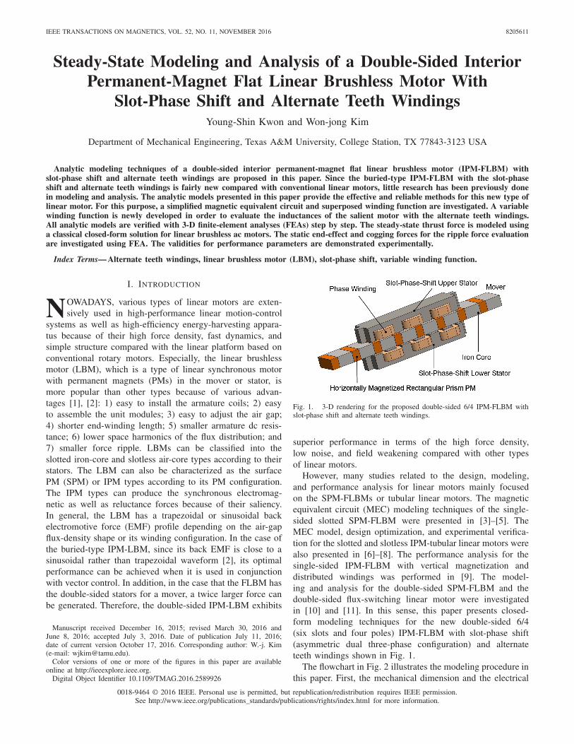
Fig. 1. 3-D rendering for the proposed double-sided 6/4 IPM-FLBM withslot-phase shift and alternate teeth windings.
superior performance in terms of the high force density,low noise, and field weakening compared with other typesof linear motors.
However, many studies related to the design, modeling,and performance analysis for linear motors mainly focusedon the SPM-FLBMs or tubular linear motors. The magneticequivalent circuit (MEC) modeling techniques of the single-sided slotted SPM-FLBM were presented in [3]–[5]. TheMEC model, design optimization, and experimental verifica-tion for the slotted and slotless IPM-tubular linear motors werealso presented in [6]–[8]. The performance analysis for thesingle-sided IPM-FLBM with vertical magnetization anddistributed windings was performed in [9]. The model-ing and analysis for the double-sided SPM-FLBM and thedouble-sided flux-switching linear motor were investigatedin [10] and [11]. In this sense, this paper presents closed-form modeling techniques for the new double-sided 6/4(six slots and four poles) IPM-FLBM with slot-phase shift(asymmetric dual three-phase configuration) and alternateteeth windings shown in Fig. 1.
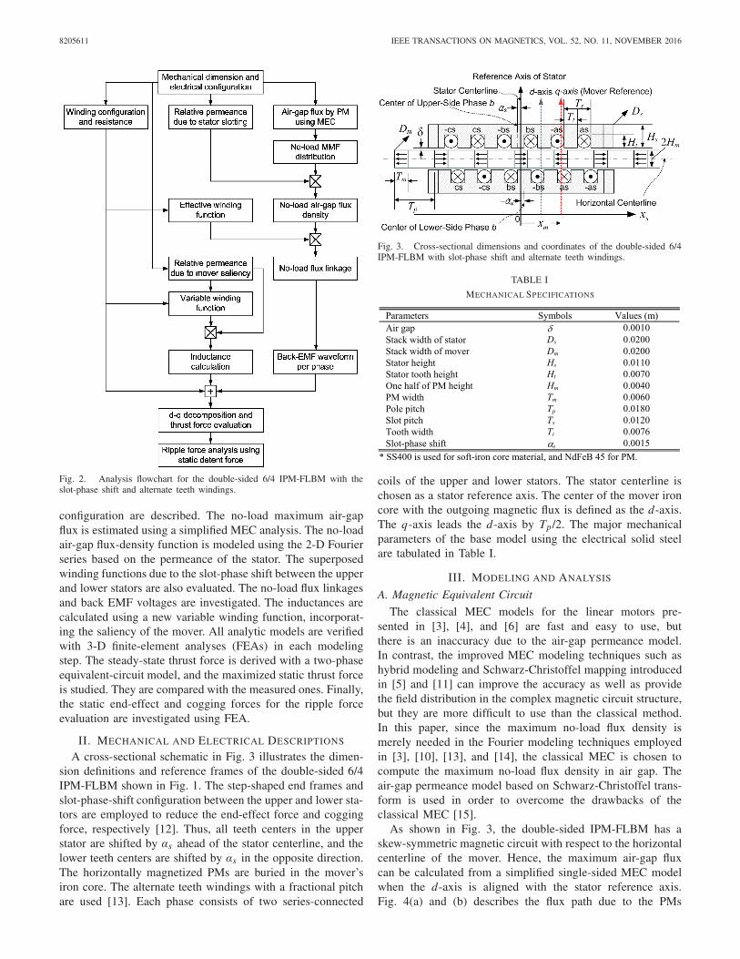
The flowchart in Fig. 2 illustrates the modeling procedure inthis paper. First, the mechanical dimension and the electrical
8205611 IEEE TRANSACTIONS ON MAGNETICS, VOL. 52, NO. 11, NOVEMBER 2016
Fig. 2. Analysis flowchart for the double-sided 6/4 IPM-FLBM with theslot-phase shift and alternate teeth windings.
configuration are described. The no-load maximum air-gapflux is estimated using a simplified MEC analysis. The no-loadair-gap flux-density function is modeled using the 2-D Fourierseries based on the permeance of the stator. The superposedwinding functions due to the slot-phase shift between the upperand lower stators are also evaluated. The no-load flux linkagesand back EMF voltages are investigated. The inductances arecalculated using a new variable winding function, incorporat-ing the saliency of the mover. All analytic models are verifiedwith 3-D finite-element analyses (FEAs) in each modelingstep. The steady-state thrust force is derived with a two-phaseequivalent-circuit model, and the maximized static thrust forceis studied. They are compared with the measured ones. Finally,the static end-effect and cogging forces for the ripple forceevaluation are investigated using FEA.
II. MECHANICAL AND ELECTRICAL DESCRIPTIONS
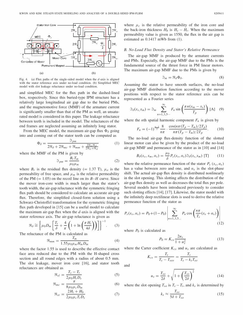
A cross-sectional schematic in Fig. 3 illustrates the dimen-sion definitions and reference frames of the double-sided 6/4IPM-FLBM shown in Fig. 1. The step-shaped end frames andslot-phase-shift configuration between the upper and lower sta-tors are employed to reduce the end-effect force and coggingforce, respectively [12]. Thus, all teeth centers in the upperstator are shifted by αs ahead of the stator centerline, and thelower teeth centers are shifted by αs in the opposite direction.The horizontally magnetized PMs are buried in the mover’siron core. The alternate teeth windings with a fractional pitchare used [13]. Each phase consists of two series-connected
Fig. 3. Cross-sectional dimensions and coordinates of the double-sided 6/4IPM-FLBM with slot-phase shift and alternate teeth windings.
TABLE I
MECHANICAL SPECIFICATIONS
coils of the upper and lower stators. The stator centerline ischosen as a stator reference axis. The center of the mover ironcore with the outgoing magnetic flux is defined as the d-axis.The q-axis leads the d-axis by Tp/2. The major mechanicalparameters of the base model using the electrical solid steelare tabulated in Table I.
III. MODELING AND ANALYSIS
A. Magnetic Equivalent Circuit
The classical MEC models for the linear motors pre-sented in [3], [4], and [6] are fast and easy to use, butthere is an inaccuracy due to the air-gap permeance model.In contrast, the improved MEC modeling techniques such ashybrid modeling and Schwarz-Christoffel mapping introducedin [5] and [11] can improve the accuracy as well as providethe field distribution in the complex magnetic circuit structure,but they are more difficult to use than the classical method.In this paper, since the maximum no-load flux density ismerely needed in the Fourier modeling techniques employedin [3], [10], [13], and [14], the classical MEC is chosen tocompute the maximum no-load flux density in air gap. Theair-gap permeance model based on Schwarz-Christoffel trans-form is used in order to overcome the drawbacks of theclassical MEC [15].
As shown in Fig. 3, the double-sided IPM-FLBM has askew-symmetric magnetic circuit with respect to the horizontalcenterline of the mover. Hence, the maximum air-gap fluxcan be calculated from a simplified single-sided MEC modelwhen the d-axis is aligned with the stator reference axis.Fig. 4(a) and (b) describes the flux path due to the PMs
KWON AND KIM: STEADY-STATE MODELING AND ANALYSIS OF A DOUBLE-SIDED IPM-FLBM 8205611
Fig. 4. (a) Flux paths of the single-sided model when the d-axis is alignedwith the stator reference axis under no-load condition. (b) Simplified MECmodel with slot leakage reluctance under no-load condition.
and simplified MEC for the flux path in the dashed-linedbox, respectively. Since this buried-type IPM structure has arelatively large longitudinal air gap due to the buried PMs,and the magnetomotive force (MMF) of the armature currentis significantly smaller than that of the PM as well, an unsatu-rated model is considered in this paper. The leakage reluctancebetween teeth is included in the model. The reluctances of theend frames are neglected assuming an infinitely long stator.
From the MEC model, the maximum air-gap flux �δ goinginto and coming out of the stator teeth can be computed as
�δ = �pm
2�δ + 2�mc + �mm + 2�st �sl2�st +�sl
(1)
where the MMF of the PM is given by
�pm = Br Tm
μ0μm(2)
where Br is the residual flux density (= 1.37 T), μo is thepermeability of free space, and μm is the relative permeabilityof the PM (= 1.05) on the recoil line on its B–H curve. Sincethe mover iron-core width is much larger than the stator’stooth width, the air-gap reluctance with the symmetric fringingflux path should be considered to calculate an accurate air-gapflux. Therefore, the simplified closed-form solution using aSchwarz-Christoffel transformation for the symmetric fringingflux path developed in [15] can be a useful model to calculatethe maximum air-gap flux when the d-axis is aligned with thestator reference axis. The air-gap reluctance is given as
�δ∼=
{μ0 Dm
[Tt
δ+ 4
π
(1 + ln
(π Ht
4δ
))]}−1
. (3)
The reluctance of the PM is calculated as
�mm = Tm
1.55μ0μm Hm Dm(4)
where the factor 1.55 is used to describe the effective contactface area reduced due to the PM with the H-shaped crosssection and all round edges with a radius of about 0.5 mm.The slot leakage, mover iron core [16], and stator toothreluctances are obtained as
�sl = Ts − Tt
2μ0 Ht Ds(5)
�mc = π
8μ0μc Dm(6)
�st = 2Ht + Hb
2μ0μcTt Ds(7)
where μc is the relative permeability of the iron core andthe back-iron thickness Hb is Hs − Ht . When the maximumpermeability value is given as 1550, the flux in the air gap isestimated as 0.1417 mWb from (1).
B. No-Load Flux Density and Stator’s Relative Permeance
The air-gap MMF is produced by the armature currentsand PMs. Especially, the air-gap MMF due to the PMs is thefundamental source of the thrust force in PM linear motors.The maximum air-gap MMF due to the PMs is given by
�m = �δ�δ. (8)
Assuming the stator to have smooth surfaces, the no-loadair-gap MMF distribution function according to the moverpositions with respect to the stator reference axis can berepresented as a Fourier series
�δ(xs,xm) = �m
∞∑n=1,3,5···
Fn sin
(πn(xm − xs)
Tp
)[A] (9)
where the nth spatial harmonic component Fn is given by
Fn = (−1)n−1
28
nπ· cos(nπ(Tp − Tm)/2Tp)
nπ(Tp − Tm)/2Tp. (10)
The no-load air-gap flux-density function of the slottedlinear motor can also be given by the product of the no-loadair-gap MMF and permeance of the stator as in [10] and [14]
Bδ(xs, xm, αs) = μ0
δPs(xs, αs)�δ(xs,xm) [T] (11)
where the relative permeance function of the stator Ps (xs, αs )has a value between zero and one, and αs is the slot-phaseshift. The actual air-gap flux density is distributed nonlinearlyin the slot opening. This slotting affects the distribution of theair-gap flux density as well as decreases the total flux per pole.Several models have been introduced previously to considersuch slotting effects [14], [17]. Likewise, the stator model withthe infinitely deep rectilinear slots is used to derive the relativepermeance function of the stator as
Ps(xs, αs) = P0+(1− P0)
∣∣∣∣∣∣∞∑
n=1,3,5...
Pn cos
(nπ
Ts(xs + αs)
)∣∣∣∣∣∣(12)
where P0 is calculated as
P0 = Kcs2us
1 + u2s
(13)
where the Carter coefficient Kcs and us are calculated as
Kcs = Ts
Ts − Tseo= Ts
Ts − ks Tso
and
us = Tso
2δ+
√1 +
(Tso
2δ
)2
(14)
where the slot opening Tso is Ts − Tt , and ks is determined by
ks ≈ Tso
5δ + Tso(15)
8205611 IEEE TRANSACTIONS ON MAGNETICS, VOL. 52, NO. 11, NOVEMBER 2016
Fig. 5. (a) FE flux-density vector paths in the midcross-section plane. (b) Flux-density distribution in the cut-through section B-B′. (c) Flux-density distributionin the midplane A-A′ of the air gap between the upper stator and the mover. (d) Flux-density distribution in the cut-through section C-C′ when the d-axis isaligned with the stator reference axis under the no-load condition.
and the nth harmonic component Pn is computed as
Pn = (−1)n−1
24
π· sin (nπ (1 − ks) Tso/4Ts)
nπ (1 − ks) Tso/4Ts
× cos
(nπ (1 + ks) Tso
4Ts
). (16)
The result in Fig. 5(a) shows the flux-density vector pathsand magnitude in the midcross-section plane of the 3-D FEAwhen the d-axis is aligned with the stator reference axisunder the no-load condition. The flux-density contour plots ofthe midplane A-A′ in Fig. 5(b) and the cut-through sectionsB-B′ and C-C′ in Fig. 5(c) and (d) show that the flux-density distribution for the flux vector in the midcross-sectionplane can be used as a typical distribution in this short-stack-width linear motor because it is uniformly distributed in theentire stack width. Fig. 6(top) and (bottom) illustrates the air-gap flux-density distributions of the upper and lower sidesincluding the slot-phase shift and slotting effect in the upperand lower air gaps. The analytic models with a maximum air-gap flux density of 0.642 T are in good agreement with theFEA results of 0.639 T. This implies that the air-gap flux andrelative permeance functions are modeled accurately.
C. DC Resistance of Armature Winding
The armature dc resistance is one of the most importantelectrical parameters in electric machines from the efficiencypoint of view. Assuming that the skin effect by the alter-nating current and the flux in the winding are negligible,the dc resistance calculation of the uniformly concentratedrectangular winding is straightforward. Fig. 7(a) and (b) showsthe dimensions and photograph of the uniformly concentratedrectangular armature winding used in this paper.
The dc resistance of a winding is dependent on the operationtemperature of the electric machine. The variation of armature
Fig. 6. Predicted air-gap flux density distributions for the upper-side (top)and lower-side (bottom) air gaps when the d-axis is aligned with the statorreference axis under the no-load condition.
Fig. 7. Uniformly concentrated rectangular winding. (a) Dimension defini-tions of the armature winding. (b) Photograph of the armature winding.
resistance in the temperature range from 0 °C to 150 °C isexpressed by
Ra = R20(1 + α20(T − 20°)) (17)
where R20 and α20 are the resistance and the temperaturecoefficient at 20 °C, respectively, T is the given temperature,and α20 is 0.00393 1/°C for the copper wire. According to
KWON AND KIM: STEADY-STATE MODELING AND ANALYSIS OF A DOUBLE-SIDED IPM-FLBM 8205611
Ohm’s law, the resistance R20 at 20 °C is given by
R20 = ρculcu
Scu= 4ρculac N
π D2c
(18)
where ρcu is the resistivity of copper (1.7 × 10⁻⁸ � · m),lcu is the total length of a winding, and Scu and Dc are thecross-sectional area of the conductor and the diameter of thecopper wire, respectively. The average length lac per turn canbe estimated as 2Ts + lo + li , where lo and li are the outer andinner lengths of a coil, respectively. The number of turns Nper winding can be calculated as
N = k f Acu
D2ci
= k f HcTso
D2ci
(19)
where Dci is the diameter of copper wire with the insulationlayer, Acu is the cross-sectional area of the slot, k f is the fillfactor of the slot, and Hc is the coil height. From (17) and (18),the dc resistance per winding can be written as
Ra = [4ρcula c N(1 + α20(T − 20◦))]/π D2c . (20)
where Hc, lo, li , the outer width wo, and the inner widthwi of a winding were chosen as 0.005, 0.028, 0.021, 0.016,and 0.0078 m, respectively. The wire of the diameter Dci of0.00045 m (bondable cooper wire of 26 AWG) was used.As a result, the number of turns of 85 was achieved. Thedc resistance per winding was calculated as 0.825 and 1.25 �at 20 °C and 150 °C, respectively. The actual resistance perwinding was measured as 0.836 �. Thus, the total dc resis-tance per phase of the double-sided model became 1.672 �.
D. No-Load Flux Linkage and Back EMF Voltage
The total flux linkage in the IPM-FLBM is expressed as
λphase = λa + λpm (21)
where λa is the armature flux linkage due to the phase currentsand λpm is the no-load flux linkage due to the mover PMs.The no-load flux linkage of a winding is maximized when thed-axis is aligned with the centerline of the winding tooth ofeach winding. The no-load flux linkage per winding with theslot-phase shift can be calculated as follows.
λpm_coil (xm, αs , β) = Ds
∫ 2Tp
−2Tp
N(xs , αs , β)Bδ(xs, xm, αs)dxs
(22)
where N(xs , αs , β) is the generalized winding function [18],and β is −2Ts , 0, and 2Ts for phases a, b, and c, respectively.The slot-phase-shift term is αs and −αs for the upper andlower stators, respectively. Assuming the stator has a smoothsurface, the generalized winding function is given as
where the first term of the right-hand side is the turns functionand the second term is the average turns function. Therefore, ifeach winding is uniformly concentrated as illustrated in Fig. 7and has the period of 2Ts by the alternate teeth winding
Fig. 8. Superposed winding functions of phases a, b, and c when a coil hasthe number of turns of 85.
arrangement, the winding function with the slot-phase shiftcan be written in the form of a Fourier series as follows.
N(xs , αs , β) = 2N∞∑
n=1
Nnsin(nπ/4)
nπcos
(nπ(xs +β+αs)
2Tp
)
(24)
where the nth spatial harmonic winding factor Nn for theuniformly concentrated winding is given by
Nn = 4Tp
nπTso sin(nπ/4)sin
(nπTs
4Tp
)sin
(nπTso
4Tp
). (25)
From (24), six winding functions are developed, and a pair ofwinding functions for the same phase have the offset of Ts /6between each other. However, since the windings of the upperand lower stators for the same phase are connected in series,the two winding functions of the upper and lower sides arespatially superposed. Consequently, the new three superposedwinding functions can be derived as
Nphase(xs, β) = N(xs , αs , β) + N(xs ,−αs , β)
= 4N∞∑
n=1
Nnsin(nπ/4)
nπcos
(nπαs
2Tp
)
× cos
(nπ(xs + β)
2Tp
). (26)
Fig. 8 shows the six slot-phase-shift winding functions and thenew three superposed winding functions for each phase.
Eventually, the no-load flux linkages for each phase can beobtained using the superposed winding functions (26) and theair-gap flux-density function (11) as follows.
λpm_phase(xm, β) = Ds
∫ 2Tp
−2Tp
Nphase(xs, β)Bδ(xs, xm, 0)dxs
(27)
Fig. 9 illustrates that the no-load flux linkages of (27)have the sinusoidal waveforms. As expected, the maximum
8205611 IEEE TRANSACTIONS ON MAGNETICS, VOL. 52, NO. 11, NOVEMBER 2016
Fig. 9. Analytic and FEA results of the no-load flux linkages for each phaseaccording to the mover positions.
no-load flux linkage for each phase occurs when the d-axisis aligned with the superposed winding centerline rather thanthe individual winding tooth centerline. This good agreementbetween the FEA and the analytic solution indicates that thesuperposed winding function is valid in the slot-phase-shiftstructure. The maximum flux linkages for phase b in theanalytic solution and the FEA are calculated as around 21.8-mWb turns and simulated as 22.1-mWb turns, respectively.
The phase-to-neutral back EMF can be derived through dif-ferentiating the flux linkage in (27) for the mover displacementxm with respect to time as follows.
ephase(xm, β) = dλpm
dt= Ds
∫ 2Tp
−2Tp
Nphase(xs, β)
×d Bδ(xs, xm , 0)
dtdxs (28)
Fig. 10 shows that the phase-to-neutral back EMFs of theanalytic model are in good agreement with the FEA resultsfor each phase. The eddy-current loss is not considered in thissimulation. The phase-to-neutral back-EMF constants in theFEA and the analytic solution are evaluated as 3.93 V·s/mand are computed as 3.75–3.95 V·s/m, respectively.
E. Inductance Calculations
The self-inductance consists of the magnetizing,harmonic-leakage, slot-leakage, end-winding-leakage, andtooth-top-leakage (zigzag-leakage) inductances [17], [18]. Theend-winding- and tooth-top-leakage inductances in a commondesign practice are often ignored because their values aremuch smaller than other components. Thus, it is assumedthat the tooth-top-leakage inductance of the open slot isnegligible in this paper. However, since the end-winding-leakage inductance cannot be ignored in the nonoverlappingwinding machine with a short stack width close to the polepitch [19], the self-inductance of a phase configured withtwo series-connected nonoverlapping concentrated windingsof the upper and lower stators can be expressed as
Ls(xm) = (Q/3)Lu + (Q/6)Lew + Lm(xm) (29)
where Lu is the slot leakage inductance per slot, Q is thetotal slot number of the upper and lower stators, Lew isthe end-winding-leakage inductance per winding, and Lm isthe total magnetizing inductance per phase. In the case of theiron-core SPM configured with the distributed winding, the
Fig. 10. Analytic and FEA results of the phase-to-neutral back EMFs foreach phase when the mover has a linear speed of 0.5 m/s.
Fig. 11. Variable winding function model in the IPM-FLBM: flux pathswhen the d-axis is aligned with the winding tooth center (top) and when theq-axis is aligned with the winding tooth center (bottom).
magnetizing inductance can be calculated using the general-ized winding function given in (23) and constant air gap. Thisis because the generalized winding function is defined underthe assumption that the sum of incoming and outgoing fluxesin the entire air gap between the stator and mover is zero asfollows. ∫ 2π
0N(θs)dθs = 0 (30)
where θs is the angle of the stator. However, as shownin Fig. 11(top) and (bottom), the fluxes induced by thearmature MMF in the buried-type IPM configuration are notdistributed in the entire air gap because of the alternateteeth windings and the large air gap between the mover ironcores. Thus, the generalized winding function is unavailable tocalculate the inductance of this configuration. Furthermore, thegeneralized winding function cannot evaluate the variation ofthe maximum magnitude of MMF in the air gap according tothe mover positions. For example, when the d-axis is alignedwith the winding tooth center as shown in Fig. 11(top), theair-gap flux density is significantly decreased due to the largeair gap between the stator teeth and both sides of the iron core,and its magnitude is much less when the q-axis is aligned withthe same tooth center as shown in Fig. 11(bottom). However,since the inductance calculation using (24) can evaluate onlythe cross-sectional area corresponding to the mover permeanceprofile, the inductance of the d-axis is calculated to be a muchlarger value than that of the q-axis.
KWON AND KIM: STEADY-STATE MODELING AND ANALYSIS OF A DOUBLE-SIDED IPM-FLBM 8205611
Therefore, a new variable winding function based on themodified winding function [20] is developed in this paper. Thevariable winding function has the flux distribution range from2σmin to 2σmax . They are determined by the variation of theaverage permeance of the observing window according to themover position versus the average permeance of the referencewindow. The distribution range variable σ with respect to thewinding tooth center can be calculated as
σ = σ0 + k
2
[〈Pm(xs, xm)〉σ0−σ0− 〈Pm(xs, xm)〉Tp
−Tp
](31)
where 〈Pm(xs , xm)〉 is the average relative permeance functionof the mover in a given range. The relative permeance functionof the mover is given as
Pm(xs, xm) = P0 + (1 − P0)
×∣∣∣∣∣∣
∞∑n=1,3,5...
Pn cos
(nπ
Tp(xs −xm)− nπ
2
)∣∣∣∣∣∣ (32)
where all coefficients in (32) can be calculated using (13)–(16)after replacing Ts and Tso with Tp and Tm , respectively. Theobserving range 2σ0 is given as 2Tp − Tm from Fig. 11. Thecoefficient k is chosen as a number that makes the minimumvalue of the calculation result of (31) be equal to σmin(= 2Ts),as shown in Fig. 11. The new winding function of phase b inthe upper side using the variable range is given by
VMx (xs, xm, αs) = nx (xs, αs)
−∫ σ−σ nx (xs, αs)Pm(xs, xm)dxs
2σ 〈Pm(xs, xm)〉σ−σ
. (33)
The variable winding function in the lower side can beachieved replacing αs with −αs . Fig. 12 illustrates that boththe magnitude and the distribution range are minimized whenthe d-axis is aligned with the winding tooth center, and theyare maximized when the q-axis is aligned with the windingtooth center.
Therefore, the magnetizing inductance of the double-sidedIPM-FLBM using (33) can be represented as
Lxm(xm) = μ0 Ds
δ
∫ 2Tp
−2Tp
(VM2
x (xs, xm, αs)
+ VM2x(xs, xm,−αs)
) × Pm(xs, xm)dxs (34)
where the subscript x represents each phase. Similarly, themutual inductance is also given as
Lxy(xm)
= μ0 Ds
δ
∫ 2Tp
−2Tp
(VMx (xs, xm, αs)VMy(xs, xm , αs)
+ VMx(xs, xm,−αs)VMy(xs, xm,−αs))Pm(xs, xm)dxs .
(35)
The slot-leakage inductance per slot is calculated as 0.151 mHusing a classical equation as [17]
Lu = μ0 Ds N2
Tso
(Ht − 2
3Hc
). (36)
The analytic model for the end-winding-leakage inductancein the nonoverlapping winding PM machine is developed
Fig. 12. Variable winding function of phase b in the upper and lower sideswhen the d-axis is aligned with the stator reference axis (top) and when theq-axis is aligned with the stator reference axis (bottom).
Fig. 13. Self-inductance distributions of each phase according to the moverpositions.
in [19]. This equation takes the end-winding geometry andlaminated stack effect into account. If adopting this equationinto the double-sided IPM linear motor, since the average coilradius can be assumed to be 3Ts /π , the end-winding-leakageinductance per winding can be expressed as
Lew = 1.257
(6Tsle
π(wo − wi )
)K N2 (37)
where the average end length le is wo + (li − Ds)/2 and theconstant K is given as
K = k1 − k2 (38)
where k1 and k2 are written as a function of the dimensionalvariables a, b, and c in [19]. These variables can be givenas 3Ts /π , wo − wi , and Hc, respectively, in the double-sidedIPM-FLBM. The end-winding-leakage inductance per windingis computed as 0.140 mH.
The self-inductance distributions in Fig. 13 illustrate thateach inductance has its maximum value when the q-axis isaligned with the corresponding superposed axis. Although the
8205611 IEEE TRANSACTIONS ON MAGNETICS, VOL. 52, NO. 11, NOVEMBER 2016
TABLE II
AVERAGE VALUES OF INDUCTANCES
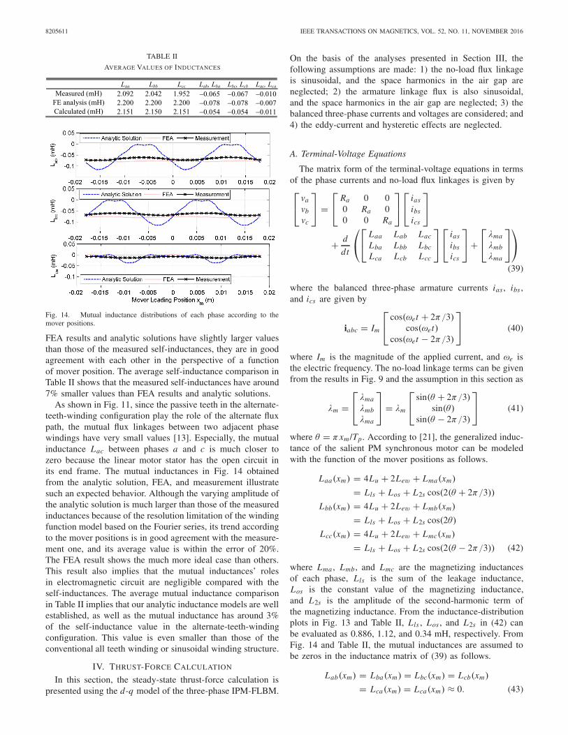
Fig. 14. Mutual inductance distributions of each phase according to themover positions.
FEA results and analytic solutions have slightly larger valuesthan those of the measured self-inductances, they are in goodagreement with each other in the perspective of a functionof mover position. The average self-inductance comparison inTable II shows that the measured self-inductances have around7% smaller values than FEA results and analytic solutions.
As shown in Fig. 11, since the passive teeth in the alternate-teeth-winding configuration play the role of the alternate fluxpath, the mutual flux linkages between two adjacent phasewindings have very small values [13]. Especially, the mutualinductance Lac between phases a and c is much closer tozero because the linear motor stator has the open circuit inits end frame. The mutual inductances in Fig. 14 obtainedfrom the analytic solution, FEA, and measurement illustratesuch an expected behavior. Although the varying amplitude ofthe analytic solution is much larger than those of the measuredinductances because of the resolution limitation of the windingfunction model based on the Fourier series, its trend accordingto the mover positions is in good agreement with the measure-ment one, and its average value is within the error of 20%.The FEA result shows the much more ideal case than others.This result also implies that the mutual inductances’ rolesin electromagnetic circuit are negligible compared with theself-inductances. The average mutual inductance comparisonin Table II implies that our analytic inductance models are wellestablished, as well as the mutual inductance has around 3%of the self-inductance value in the alternate-teeth-windingconfiguration. This value is even smaller than those of theconventional all teeth winding or sinusoidal winding structure.
IV. THRUST-FORCE CALCULATION
In this section, the steady-state thrust-force calculation ispresented using the d-q model of the three-phase IPM-FLBM.
On the basis of the analyses presented in Section III, thefollowing assumptions are made: 1) the no-load flux linkageis sinusoidal, and the space harmonics in the air gap areneglected; 2) the armature linkage flux is also sinusoidal,and the space harmonics in the air gap are neglected; 3) thebalanced three-phase currents and voltages are considered; and4) the eddy-current and hysteretic effects are neglected.
A. Terminal-Voltage Equations
The matrix form of the terminal-voltage equations in termsof the phase currents and no-load flux linkages is given by⎡⎣ va
vb
vc
⎤⎦ =
⎡⎣ Ra 0 0
0 Ra 00 0 Ra
⎤⎦
⎡⎣ ias
ibs
ics
⎤⎦
+ d
dt
⎛⎝
⎡⎣ Laa Lab Lac
Lba Lbb Lbc
Lca Lcb Lcc
⎤⎦
⎡⎣ ias
ibs
ics
⎤⎦ +
⎡⎣ λma
λmb
λma
⎤⎦
⎞⎠
(39)
where the balanced three-phase armature currents ias , ibs ,and ics are given by
iabc = Im
⎡⎣ cos(ωet + 2π/3)
cos(ωet)cos(ωet − 2π/3)
⎤⎦ (40)
where Im is the magnitude of the applied current, and ωe isthe electric frequency. The no-load linkage terms can be givenfrom the results in Fig. 9 and the assumption in this section as
λm =⎡⎣ λma
λmb
λma
⎤⎦ = λm
⎡⎣ sin(θ + 2π/3)
sin(θ)sin(θ − 2π/3)
⎤⎦ (41)
where θ = πxm /Tp. According to [21], the generalized induc-tance of the salient PM synchronous motor can be modeledwith the function of the mover positions as follows.
Laa(xm) = 4Lu + 2Lew + Lma(xm)
= Lls + Los + L2s cos(2(θ + 2π/3))
Lbb(xm) = 4Lu + 2Lew + Lmb(xm)
= Lls + Los + L2s cos(2θ)
Lcc(xm) = 4Lu + 2Lew + Lmc(xm)
= Lls + Los + L2s cos(2(θ − 2π/3)) (42)
where Lma , Lmb , and Lmc are the magnetizing inductancesof each phase, Lls is the sum of the leakage inductance,Los is the constant value of the magnetizing inductance,and L2s is the amplitude of the second-harmonic term ofthe magnetizing inductance. From the inductance-distributionplots in Fig. 13 and Table II, Lls , Los , and L2s in (42) canbe evaluated as 0.886, 1.12, and 0.34 mH, respectively. FromFig. 14 and Table II, the mutual inductances are assumed tobe zeros in the inductance matrix of (39) as follows.
Lab(xm) = Lba(xm) = Lbc(xm) = Lcb(xm)
= Lca(xm) = Lca(xm) ≈ 0. (43)
KWON AND KIM: STEADY-STATE MODELING AND ANALYSIS OF A DOUBLE-SIDED IPM-FLBM 8205611
Fig. 15. Photograph of the experimental setup to measure the inductancesand steady-state thrust forces.
B. Steady-State Thrust-Force Calculation
In the rotary machine, the terminal voltage equations of thetwo-phase circuit through the d-q decomposition of (39) aregiven as
Vqs = (Rs + Lq p)Iqs + ωm Ld Ids + ωmλdm
Vds = (Rs + Ld p)Ids − ωm Lq Iqs (44)
where p is d/dt , Iq and Id are the q-axis and d-axis currents,ωm is the mechanical angular speed, and λdm is the d-axisflux linkage. According to [21], the generalized forms for theq- and d-axis inductances Lq and Ld in the salient polemachine are given as
Lq = Lls + Los + L2s
and
Ld = Lls + Los − L2s . (45)
Thus, the q- and d-axis inductances are calculated as2.34 and 1.66 mH, respectively. Since the linear speed Vm ofthe linear motor is equal to the synchronous speed of thetraveling magnetic field, the linear and rotating speeds havethe following relationship:
Vm = ωm Tp/π. (46)
From (44)–(46), the terminal voltage equations according tothe mover speed can be written as
Vqs = (Rs + Lq p)Iqs + π
Tp(Ld Ids + λdm) Vm
Vds = (Rs + Ld p)Ids − π
TpLq Iqs Vm . (47)
The mechanical power can be obtained by subtracting theohmic loss and the rate of the change of the stored energy inthe magnetic circuit from the instantaneous power computedwith (47) [20]. The developed thrust force can be expressedin terms of the d- and q-axis current as follows.
Fx = 3π
2Tp(λdm Iqs + (Ld − Lq)Ids Iqs) (48)
Fig. 16. Measured static forces according to the moving direction whenIa = Ic = 8.66 A and Ib = 0 A (top) and the static force differences betweenthe positive and negative entry directions at the same positions (bottom).
V. STEADY-STATE FORCE VALIDATION
Fig. 15 shows the experimental setup that measures theinductances and steady-state thrust forces of the double-sided6/4 IPM-FLBM modeled in this paper. A 300-W dc powersupply was used. A precision bidirectional load cell with a0.1% nonlinearity and a micrometer head with an accuracyof ±0.0005 mm were employed in order to measure thesteady-state thrust forces according to the mover positions.The inductances were measured using a 120-Hz sinusoidalcurrent source of 1.0 A.
In theory, the resultant force superposed by the upper andlower stators with slot-phase shift is developed with respectto the new stator reference axis. It is not affected by thedirection of motion of the mover. However, the results inFig. 16 show that there are small differences in the staticforces according to the mover’s direction and position. Thisimplies that the actual IPM-FLBM has the average hystereticforce of −0.6 N depending on the entry direction of the moveralthough its value is much less than the maximum force. Thishysteretic force seems to be caused by the imperfections inthe mechanical structure and PM.
The thrust force of (48) is composed of two distinctmechanisms. The first term corresponds to the magnetizingforce occurring between Iqs and the PM, whereas the secondterm is the reluctance force generated due to the differencesbetween the d- and q-axis inductances. Assuming that thesupply voltage and current are limited and that the suppliedcurrent vector leads the q-axis current by the phase angle γ ,in steady state, (48) can be rewritten using the magnitude ofthe current vector Is as
Fx = 3π
2Tp
(λm Is cos γ + 1
2(Lq − Ld )I 2
s sin 2γ
)(49)
where Is is given as
Is =√
I 2q + I 2
d . (50)
8205611 IEEE TRANSACTIONS ON MAGNETICS, VOL. 52, NO. 11, NOVEMBER 2016
Fig. 17. Thrust force components according to the current phase angle γwhen the magnitude of the current vector Is of 10 A is applied.
Fig. 18. Force-to-current ratios in the MFC and FOC schemes.
Thus, the maximized thrust force can be obtained throughfield weakening due to the d-axis armature reaction. Fig. 17shows that the maximum thrust force is produced when thephase angle [= tan−1(Id /Iq)] is around 15° although thereluctance force at a current vector of 10 A is not significantlylarge due to the small difference between the q- and d-axisinductances. The measured total thrust forces are achievedwithin maximum 2% error when compared with the total thrustforces in the calculation and FEA. The predicted total thrustforce using a closed-form analysis matches quite well with themeasurement and FEA.
Fig. 18 shows that the maximum force control (MFC)scheme using the reluctance force can produce more forcethan that of the field-oriented-control (FOC) scheme forthe same input power. This implies that if the residualflux density of the PM is not deteriorated by the d-axisarmature reaction at high temperature, the more the currentincreases, the larger the force difference is produced. Thecalculated force constants of the FOC and MFC were eval-uated as 5.8 and 6.1 N/A, and the measured ones were as5.9 and 6.2 N/A, respectively, in the given current range.
Fig. 19. Steady-state (top) force and detent (bottom) forces according to themover positions when Iqs and Ids are controlled as 10 and 0 A, respectively.
The measured force constants for both cases are slightly higherthan the calculated ones. It seems that the residual flux densityof the actual PM is slightly higher than that used in thecalculation and FEA. These force constants also imply that theassumption for the unsaturated MEC model in Section III-Ais reasonable in the armature current range of less than 10 A.This is because the MMF of the armature current in the small-sized PM machine is much less than that of the PM.
The force pulsation, also called force ripple, is caused bythe detent force and the switching power circuit. Unlike theconventional rotary motor, the detent force in an iron-coredPM linear motor has not only the cogging force but alsothe end-effect force [12], [22], [23]. Furthermore, since theend-effect force acting on the complicated end frame in thelinear motor exhibits the highly nonlinear behavior, there is noanalytic solution for the end-effect force until now. Therefore,in this paper, the cogging force for the infinitely long statormodel was simulated using 3-D FEA for the ripple-forcecomparison.
Fig. 19(top) and (bottom) shows the steady-state thrustforces when Iq = 10 A and Id = 0 A, and the detent forceswhen Iq = Id = 0 A, respectively. The measured detent forcein Fig. 19(bottom) shows that the cogging force predicted in anideal FEA model is distorted by the residual harmonic termof the end-effect force. As a result, the actual detent forcebecomes much larger than the cogging force of the ideal FEAmodel. Thus, the peak-to-peak cogging force in the FEA modelwas evaluated as around 1.2 N, but the actual detent force wasmeasured as 2.4 N, corresponding to approximately 2% and4% of the rated thrust force. In addition, the resultant detentforce directly affects the steady-state ripple force as shownin Fig. 19(top). Hence, the standard deviations of the steady-state forces in the FEA and measurement were evaluated as0.81 and 1.13 N, respectively. The averages of the steady-state forces in the FEA and measurement were calculated as
KWON AND KIM: STEADY-STATE MODELING AND ANALYSIS OF A DOUBLE-SIDED IPM-FLBM 8205611
58.4 and 58.9 N, respectively. Similar to the previous result,the measured average force has a 1% higher value than thesimulated one.
VI. CONCLUSION
Analytic modeling techniques were developed to analyze thedouble-sided IPM-FLBM with slot-phase shift and alternateteeth windings. A superposed winding function was estab-lished in the slot-phase shift configuration. The no-load fluxlinkages and back EMFs per phase were evaluated using thissuperposed winding technique, and its validity was verifiedby 3-D FEA. A variable winding function method was newlydeveloped in order to evaluate the inductances of the linearmotor configured with the salient iron core and alternate teethwinding. This technique improved the utility of the windingfunction in a specific structure. This was also sufficientlygeneralized to handle the same type of motor as an effectiveand reliable method. The steady-state thrust force model wasderived using the parameters obtained from these models.In the end, the proposed models were verified and analyzedthrough the static force measurements in the MFC and FOC.
REFERENCES
[1] J. F. Gieras, Z. J. Piech, and B. Z. Tomczuk, “Topologies and selec-tion,” in Linear Synchronous Motors, 2nd ed. Boca Raton, FL, USA:CRC Press, 2012, pp. 1–22.
[2] P. C. Sen, “Synchronous machines,” in Principles of Electric Machinesand Power Electronics, 2nd ed. Wiley, 1997, pp. 350–357.
[3] H. Polinder, J. G. Slootweg, M. J. Hoeijmakers, and J. C. Compter,“Modeling of a linear PM machine including magnetic saturation andend effects: Maximum force-to-current ratio,” IEEE Trans. Ind. Appl.,vol. 39, no. 6, pp. 1681–1688, Nov./Dec. 2003.
[4] B. Sheikh-Ghalavand, S. Vaez-Zadeh, and A. H. Isfahani, “An improvedmagnetic equivalent circuit model for iron-core linear permanent-magnetsynchronous motors,” IEEE Trans. Magn., vol. 46, no. 1, pp. 112–120,Jan. 2010.
[5] D. C. J. Krop, E. A. Lomonova, and A. J. A. Vandenput, “Applicationof Schwarz–Christoffel mapping to permanent-magnet linear motoranalysis,” IEEE Trans. Magn., vol. 44, no. 3, pp. 352–359, Mar. 2008.
[6] N. Bianchi, S. Bolognani, and F. Tonel, “Design criteria of a tubularlinear IPM motor,” in Proc. Int. Conf. Electr. Mach. Drives, vol. 1.Jun. 2001, pp. 1–7.
[7] J. Wang, D. Howe, and G. W. Jewell, “Analysis and design optimizationof an improved axially magnetized tubular permanent-magnet machine,”IEEE Trans. Energy Convers., vol. 19, no. 2, pp. 289–295, Jun. 2004.
[8] K. J. Meessen, J. J. H. Paulides, and E. A. Lomonova, “Modeling andexperimental verification of a tubular actuator for 20-g acceleration ina pick-and-place application,” IEEE Trans. Ind. Appl., vol. 46, no. 5,pp. 1891–1898, Sep./Oct. 2010.
[9] M. Sanada, S. Morimoto, and Y. Takeda, “Interior permanent magnetlinear synchronous motor for high-performance drives,” IEEE Trans.Ind. Appl., vol. 33, no. 4, pp. 966–972, Jul./Aug. 1997.
[10] G. Stumberger, D. Zarko, M. T. Aydemir, and T. A. Lipo, “Design andcomparison of linear synchronous motor and linear induction motor forelectromagnetic aircraft launch system,” in Proc. IEEE Int. Conf. Electr.Mach. Drives, vol. 1. Jun. 2003, pp. 494–500.
[11] D. C. J. Krop, L. Encica, and E. A. Lomonova, “Analysis of a noveldouble sided flux switching linear motor topology,” in Proc. 19th Int.Conf. Elect. Mach., Sep. 2010, pp. 1–5.
[12] Y.-S. Kwon and W.-J. Kim, “Detent-force minimization of double-sidedinterior permanent-magnet flat linear brushless motor,” IEEE Trans.Magn., vol. 52, no. 4, Apr. 2016, Art. no. 8201609.
[13] D. Ishak, Z. Q. Zhu, and D. Howe, “Comparison of PM brushlessmotors, having either all teeth or alternate teeth wound,” IEEE Trans.Energy Convers., vol. 21, no. 1, pp. 95–100, Mar. 2006.
[14] Z. Q. Zhu and D. Howe, “Instantaneous magnetic field distribution inbrushless permanent magnet DC motors. III. Effect of stator slotting,”IEEE Trans. Magn., vol. 29, no. 1, pp. 143–151, Jan. 1993.
[15] A. Balakrishnan, W. T. Joines, and T. G. Wilson, “Air-gap reluc-tance and inductance calculations for magnetic circuits using aSchwarz–Christoffel transformation,” IEEE Trans. Power Electron.,vol. 12, no. 4, pp. 654–663, Jul. 1997.
[16] J. Mühlethaler, J. W. Kolar, and A. Ecklebe, “A novel approach for 3Dair gap reluctance calculations,” in Proc. 8th Int. Conf. Power Electron.ECCE Asia, Jun. 2011, pp. 446–452.
[17] J. Pyrhönen, T. Jokinen, and V. Hrabovcová, Design of Rotating Elec-trical Machines, 1st ed. New York, NY, USA: Wiley, 2008.
[18] T. A. Lipo, Analysis of Synchronous Machines, 2nd ed. Boca Raton, FL,USA: CRC Press, 2012.
[19] J. H. J. Potgieter and M. J. Kamper, “Evaluation of calculation methodsand the effect of end-winding inductance on the performance of nonoverlap winding PM machines,” in Proc. 20th ICEM, Mar. 2012,pp. 243–249.
[20] N. A. Al-Nuaim and H. A. Toliyat, “A novel method for modelingdynamic air-gap eccentricity in synchronous machines based on modifiedwinding function theory,” IEEE Trans. Energy Convers., vol. 13, no. 2,pp. 156–162, Jun. 1998.
[21] D. W. Novotny and T. A. Lipo, Vector Control and Dynamics of ACDrives, 1st ed. London, U.K.: Oxford Univ. Press, 1996.
[22] S. W. Youn, J. J. Lee, H. S. Yoon, and C. S. Koh, “A new cogging-freepermanent-magnet linear motor,” IEEE Trans. Magn., vol. 44, no. 7,pp. 1785–1790, Jul. 2008.
[23] Y.-W. Zhu, S.-G. Lee, K.-S. Chung, and Y.-H. Cho, “Investigation ofauxiliary poles design criteria on reduction of end effect of detentforce for PMLSM,” IEEE Trans. Magn., vol. 45, no. 6, pp. 2863–2866,Jun. 2009.
Young-Shin Kwon (S’11) received the B.S. degree in control and instrumen-tation engineering from Hanyang University, Seoul, South Korea, in 1995,and the M.S. degree in control and instrumentation engineering from SeoulNational University, Seoul, in 1997. He is currently pursuing the Ph.D. degreewith the Department of Mechanical Engineering, Texas A&M University,College Station, TX, USA.
He was the Automatic Transmission System Developer with HyundaiElectronics Corporation, Icheon, South Korea, for two years, after theM.S. degree. He also developed the active seekers of guided missile systemsand naval/airborne radar systems as a Principal Researcher with LIG Nex1Corporation, Yongin, South Korea, for thirteen years. His current researchinterests include design and analysis of spatial stabilization of multiaxisplatforms, precision optomechatronics systems, and linear magnetic actuators.
Won-jong Kim (S’89–M’97–SM’03) received the B.S. (summa cum laude)and M.S. degrees in control and instrumentation engineering from SeoulNational University, Seoul, South Korea, in 1989 and 1991, respectively, andthe Ph.D. degree in electrical engineering and computer science from theMassachusetts Institute of Technology, Cambridge, MA, USA, in 1997.
He has been with the Department of Mechanical Engineering, Texas A&MUniversity, College Station, TX, USA, since 2000, where he is currentlyan Associate Professor. He was an Inaugural Holder of the Dietz CareerDevelopment Professorship II from 2007 to 2010. He holds three U.S. patentson precision positioning systems. His current research interests include theanalysis, design, and real-time control of mechatronic systems, networkedcontrol systems, and nanoscale engineering and technology.
Prof. Kim is a fellow of ASME and a member of Pi Tau Sigma.He is or was the Technical Editor of the IEEE/ASME TRANSACTIONS ON
MECHATRONICS, the ASME Journal of Dynamic Systems, Measurement andControl, the International Journal of Control, Automation, and Systems, andthe Asian Journal of Control.