103
STEALTH RC FIRMWARE 1.0.11 REFERENCE GUIDE 2/2/2016 Copyright by Chris James, 2016. Replication or reproduction in whole or in part is strictly prohibited without express written consent.

STEALTH RC
FIRMWARE 1.0.11
REFERENCE GUIDE
2/2/2016
Copyright by Chris James, 2016.
Replication or reproduction in whole or in part is strictly prohibited without express written consent.

2
1. CONTENTS
2. ACRONYMS AND TERMS ..............................................................................................................7
3. SUPPORT .....................................................................................................................................8
4. TECHNICAL SUMMARY ................................................................................................................9
4.1. OVERVIEW ..................................................................................................................................9 4.2. COMPONENTS ..............................................................................................................................9 4.3. EXAMPLE CONFIGURATIONS .......................................................................................................... 11 4.3.1. STANDARD/MINIMUM ........................................................................................................................... 11 4.3.2. ADVANCED ............................................................................................................................................ 13
5. STEALTH POCKET REMOTES ....................................................................................................... 15
5.1. FEATURES ................................................................................................................................. 15 5.2. STEALTH REMOTE LAYOUT............................................................................................................. 16 5.3. POCKET REMOTE INPUT METHODS ................................................................................................. 16 5.3.1. JOYSTICKS ............................................................................................................................................. 17 5.3.2. BUTTONS ............................................................................................................................................. 17 5.3.3. THUMB WHEELS .................................................................................................................................... 17 5.3.4. THUMB GESTURES ................................................................................................................................. 17 5.4. MAINTENANCE AND SAFETY FEATURES ............................................................................................. 23 5.4.1. FAILSAFES ............................................................................................................................................. 23 5.4.2. SAFETY STRAP ....................................................................................................................................... 23 5.4.3. CHARGING ............................................................................................................................................ 24 5.4.4. REPLACING INTERNAL BATTERIES .............................................................................................................. 26
6. STEALTH CONTROLLER RECEIVER ............................................................................................... 27
6.1. COMPONENTS ............................................................................................................................ 27 6.2. STEALTH CONTROLLER RECEIVER CONNECTIONS ................................................................................. 28 6.2.1. OVERVIEW ............................................................................................................................................ 28 6.2.2. POWER ................................................................................................................................................ 32 6.2.3. PWR - EXTERNAL POWER FOR CONTROLLER .............................................................................................. 32 6.2.4. PWRHDR ............................................................................................................................................ 32 6.2.5. SVOPWR ............................................................................................................................................ 32

3
6.2.6. SVOHDR- SERVO POWER SUPPLY ........................................................................................................... 33 6.2.7. JOIN5V - COMBINE CONTROLLER AND SERVO +5V SUPPLY ......................................................................... 33 6.2.8. DPWR - ENABLE +5V SUPPLY TO DIGITAL OUT +5V PINS............................................................................ 33 6.2.9. SERVOS - SERVO OUT CONNECTIONS (S1 TO S12) .................................................................................... 34 6.2.10. DIGITAL OUT - DISCRETE DIGITAL OUTPUT CONNECTORS (D1 TO D8) ....................................................... 34 6.2.11. ANALOG I/O - DISCRETE DIGITAL OUTPUT CONNECTORS (A1 TO A2) ........................................................ 35 6.2.12. I2C BUS.............................................................................................................................................. 35 6.2.13. PPM IN - PPM MODULE CONNECTOR ................................................................................................... 35 6.2.14. XBEE - XBEE RADIO MODULE TTL SERIAL CONNECTION ............................................................................ 36 6.2.15. SER - TTL SERIAL CONNECTION ............................................................................................................. 36 6.2.16. AUX - AUXILIARY TTL SERIAL CONNECTION ............................................................................................. 36 6.2.17. VMUSIC2 - MP3 MODULE CONNECTOR ................................................................................................ 37 6.2.18. RCSEL- RC MODE SELECT JUMPER/HEADER .......................................................................................... 37 6.2.19. SEL2 - HEADER .................................................................................................................................... 38 6.2.20. STATUS - STATUS HEADER BREAKOUT ................................................................................................... 38 6.2.21. ISP- ICSP PROGRAMMING HEADER ........................................................................................................ 38 6.3. XBEE RADIO MODULE ................................................................................................................. 39 6.3.1. CONNECTING ........................................................................................................................................ 39 6.3.2. EXAMPLE XBEE ADAPTERS ...................................................................................................................... 39 6.4. STATUS LEDS............................................................................................................................. 40 6.4.1. POWER ................................................................................................................................................ 40 6.4.2. XBEE STATUS LEDS ............................................................................................................................... 40 6.4.3. STATUS ................................................................................................................................................ 40 6.5. POWER CONSIDERATIONS ............................................................................................................. 43 6.6. COMMAND LINE INTERFACE (CLI) ................................................................................................... 45 6.6.1. CONNECTING TO THE CONSOLE VIA HARDWIRE ........................................................................................... 45 6.6.2. CONNECTING TO THE CONSOLE VIA XBEE / WIRELESS ............................................................................... 48 6.6.3. ANDROID CONNECTVITY ......................................................................................................................... 48 6.6.4. SERIAL TERMINAL SOFTWARE .................................................................................................................. 48 6.6.5. EXAMPLE OUTPUT ................................................................................................................................. 49 6.6.6. COMMANDS ......................................................................................................................................... 50 6.7. CONFIGURATION ........................................................................................................................ 51 6.7.1. EEPROM CONFIG ............................................................................................................................... 51 6.7.2. MANUAL REFRESH OF EEPROM .............................................................................................................. 52 6.7.3. "BIND" PROCEDURE ............................................................................................................................... 52 6.7.4. CONFIG FILE (CONFIG.TXT) ................................................................................................................... 53 6.7.5. GENERAL PARAMETERS ........................................................................................................................... 54 6.7.6. SOUND BANKS ...................................................................................................................................... 55 6.7.7. AUXILIARY STRING OUTPUT ..................................................................................................................... 56 6.7.8. BUTTONS ............................................................................................................................................. 56 6.7.9. THUMB GESTURES ................................................................................................................................. 57 6.7.10. COMMON NOTES ON GESTURES AND BUTTONS ........................................................................................ 57

4
6.7.11. SERVOS AND CHANNELS ........................................................................................................................ 58 6.7.12. AUTO-DOME PARAMETERS .................................................................................................................. 60 6.7.13. EXAMPLE CONFIG.TXT ....................................................................................................................... 61 6.8. MP3 MODULE (VMUSIC2) ......................................................................................................... 62 6.8.1. LINE OUT / AUDIO SETUP ....................................................................................................................... 62 6.8.2. USB FLASH DRIVE / THUMB DRIVE ........................................................................................................... 63 6.8.3. AUDIO FILES AND FORMAT ...................................................................................................................... 63 6.9. INCOMING I2C COMMANDS ........................................................................................................... 64
7. AUTO-DOME ............................................................................................................................. 65
7.1. TUNING AUTO-DOME .................................................................................................................. 66
8. SERVO AND IO EXPANDER ......................................................................................................... 68
8.1. OVERVIEW ................................................................................................................................ 68 8.2. PIN OUTS ................................................................................................................................. 68 8.2.1. VERSION 1.4 AND EARLIER: ..................................................................................................................... 68 8.2.2. VERSION 1.5 ......................................................................................................................................... 69 8.2.3. VERSION 1.6 ......................................................................................................................................... 69 8.2.4. PWR ................................................................................................................................................... 70 8.2.5. DIGITIAL I/O SERVOS 2-13 ..................................................................................................................... 70 8.2.6. ANALOG - A0 - A3 ................................................................................................................................. 70 8.2.7. I2C BUS................................................................................................................................................ 70 8.2.8. JOINV ................................................................................................................................................. 71 8.3. I2C CONNECTION ........................................................................................................................ 72 8.4. SERVO CONNECTIONS .................................................................................................................. 72 8.5. PROGRAMMING AND COMMUNICATION .......................................................................................... 73 8.6. EXAMPLE CODE .......................................................................................................................... 73 8.6.1. MINIMAL EXAMPLE ................................................................................................................................ 73
9. PPM/PWM CONVERTER ............................................................................................................ 75
9.1. OVERVIEW ................................................................................................................................ 75 9.2. CONNECTING TO A RC RECEIVER ..................................................................................................... 75 9.3. MAPPING ................................................................................................................................. 76 9.3.1. 6 CHANNEL RADIOS ............................................................................................................................... 77 9.3.2. 8 CHANNEL RADIOS ............................................................................................................................... 77 9.4. MIXING AND FAILSAFES ................................................................................................................ 78 9.5. PIN OUTS ................................................................................................................................. 78 9.6. STATUS LED .............................................................................................................................. 78

5
9.7. RC SELECT SWITCH ...................................................................................................................... 79
10. DC/DC CONVERTER .................................................................................................................. 80
11. ADDITIONAL COMPONENTS ..................................................................................................... 82
11.1. SPEED CONTROLLERS ................................................................................................................. 82 11.2. AMPLIFIERS ............................................................................................................................. 82
12. TROUBLESHOOTING/FAQ ........................................................................................................ 83
12.1. STEALTH POCKET REMOTES ......................................................................................................... 83 12.1.1. CAN I HOT-SWAP BETWEEN POCKET REMOTES AND RC MODE? .................................................................. 83 12.1.2. I LOST THE SCREW / BUTTONS AFTER I OPENED UP THE CASE - WHERE CAN I GET MORE? .................................. 83 12.1.3. WHAT BATTERY IS USED IN THE REMOTE? ................................................................................................ 83 12.1.4. HOW LONG WILL BE REMOTES RUN FOR ON A FULL CHARGE? ...................................................................... 83 12.1.5. WHAT'S THE LIFE EXPECTANCY OF A BATTERY? .......................................................................................... 83 12.1.6. HOW LONG DOES IT TAKE TO CHARGE THE BATTERY? ................................................................................. 83 12.1.7. THE BATTERY IS DEAD AND I CAN'T TELL IF THE REMOTE IS TURNED OFF OR ON ............................................... 83 12.1.8. THE YELLOW CHARGE LED IS BLINKING WHAT DOES IT MEAN? .................................................................... 84 12.1.9. CAN I USE THE REMOTES WHILE CHARGING? ............................................................................................. 84 12.1.10. THE BATTERY IS SWOLLEN OR LEAKING - WHAT SHOULD I DO? ................................................................... 84 12.1.11. CAN I REPLACE THE XBEE RADIOS? ....................................................................................................... 84 12.1.12. CAN I SWITCH MY XBEE RADIOS FROM 2.4GHZ TO 900MHZ OR VICE-VERSA? ........................................... 84 12.1.13. THE J1 AND J2 LEDS KEEP ON FLASHING ON AND OFF .............................................................................. 84 12.1.14. JOYSTICK VALUES DON'T REACH MIN/MAX (0-180) ............................................................................... 85 12.2. STEALTH CONTROLLER RECEIVER ................................................................................................... 86 12.2.1. STARTUP HANGS WHEN I HAVE AN SERVO EXPANDER ATTACHED .................................................................. 86 12.2.2. WHEN WILL THE J.E.D.I. CONTROLLER BE SUPPORTED? ............................................................................ 86 12.2.3. THE THUMBWHEELS ARE STIFF/HARD TO TURN ......................................................................................... 86 12.2.4. DO YOU SUPPORT TEECES/JEDI LOGICS .................................................................................................. 86 12.3. DRIVE SYSTEM ......................................................................................................................... 87 12.3.1. MY DROID IS VERY ERRATIC WHEN I TRY AND I CAN'T CONTROL HIM .............................................................. 87 12.3.2. MY DROID WILL NOT GO FORWARD AND TURNS IN STRANGE DIRECTIONS ...................................................... 87 12.3.3. MY DOME SPINS THE WRONG WAY ......................................................................................................... 88 12.4. SERVO I/O EXPANDER ............................................................................................................... 88 12.4.1. I HAVE A SERVO EXPANDER LOADED WITH THE EXAMPLE CODE BUT IT'S NOT RESPONDING TO I2C COMMANDS .... 88 12.4.2. CAN THE SERVO EXPANDER RANDOMLY MOVE A DOME HP? ....................................................................... 88 12.4.3. CAN I CONNECT MY JEDI HP LED BOARDS DIRECTLY TO THE STEALTH SYSTEM? ............................................. 89 12.4.4. WHAT ABOUT JEDI DISPLAY, CAN I TRIGGER THEM FROM THE STEALTH RC SETUP? ........................................ 89 12.4.5. CAN I CONTROL A TEECES LOGIC DISPLAY FROM THE STEALTH RC SETUP? .................................................... 89

6
12.5. SOUND SYSTEM ........................................................................................................................ 89 12.5.1. THERE'S STATIC COMING FROM MY SPEAKERS ........................................................................................... 89 12.5.2. THERE'S A CLICKING COMING FROM SPEAKERS .......................................................................................... 89
13. STEALTH CONTROLLER FIRMWARE ........................................................................................... 90
13.1. FIRMWARE REVISIONS AND DOWNLOADS ....................................................................................... 90 13.2. FIRMWARE UPGRADE PROCEDURE ................................................................................................ 92 13.2.1. SERIAL / USB FTDI XBOOT METHOD .................................................................................................... 92 13.2.2. UPGRADING TO XBOOT BOOTLOADER ................................................................................................... 93 13.2.3. FLASHING FIRMWARE DIRECT ................................................................................................................ 93
14. FIRMWARE CHANGES ............................................................................................................ 102
14.1. VERSION 1.0.10 ..................................................................................................................... 102 14.2. VERSION 1.0.11 ..................................................................................................................... 102

7
2. ACRONYMS AND TERMS
Arduino Arduino is a single-board microcontroller. The hardware consists of an open-source hardware board designed around an 8-bit Atmel AVR microcontroller. The software consists of a standard programming language compiler and a boot loader that executes on the microcontroller.
CLI Command Line Interface DC Direct Current DOUT & DO Digital Output – used for communicating to other devices EEPROM Electrically Erasable Programmable Read-Only Memory and is a type of non-volatile memory
used in computers and other electronic devices to store small amounts of data that must be saved when power is removed.
FS Fail Safe – upon failure detection, to return all outputs to known safe state GHz Gigahertz GND Ground I2c Inter-Integrated Circuit (multi-master serial bus) Li-PO Lithium-ion polymer batteries, polymer lithium ion or more commonly lithium polymer batteries
(abbreviated Li-poly, Li-Pol, LiPo, LIP, PLI or LiP) are rechargeable batteries. MHz Megahertz MP3 MP3 is an audio-specific format that was designed by the Moving Picture Experts Group (MPEG) PPM Pulse Position Modulation PWM Pulse Width Modulation RC Radio Control TTL Transistor-Transistor Logic – digital logic levels where a “1” is > 1.6 Volts and a “0” is below 0.8
Volts SCR Stealth Controller Receiver Speed Controller
An electronic speed control or ESC is an electronic circuit with the purpose to vary an electric motor's speed, its direction and possibly also to act as a dynamic brake. ESCs are often used on electrically powered radio controlled models and robots.
SPR Stealth Pocket Remote(s) SRC Stealth RC (Radio Control) USB Universal Serial Bus (USB) is an industry standard that defines the cables, connectors and
communications protocols used in a bus for connection, communication, and power supply between computers and electronic devices.
V Voltage XBEE XBee is the brand name from Digi International for a family of form factor compatible radio
modules.

8
3. SUPPORT
This guide is indented for Stealth RC Controllers v2.2 and above running Firmware release 1.0.11.
Visit our support forum for assistance, latest information, documentation and firmware releases.
www.surerobotics.com/support

9
4. TECHNICAL SUMMARY
4.1. OVERVIEW
Stealth RC is a compact, fully integrated, advanced radio control with integrated sound system. It's designed for droid and robot builders to replace a conventional Radio Control (RC) setup. However, it can be used in conjunction with a conventional RC radio if desired.
• Super small - fit in the palm of your hand - allowing the droid operator to be covert or stealth like • Light weight - 2 ounces vs. typical 3 pounds RC Remote • Thumb Gestures adds an additional way to trigger actions and sounds beyond normal buttons • Integrated MP3 Sound System • Radios operate at either 2.4GHz or 900MHz (later recommended for more range and less interference) • Advanced Digital Communications - Digital Out & i2c Communication • Highly configurable via a Command Line Interface (CLI) or USB Thumb Drive • Control up to 12 Servos directly, or dozens thru Servo Expansion Modules including advanced scripting • As a bonus when using RC Mode you can trigger sounds and enter Thumb Gestures on your conventional
RC remote • Advanced wireless console / command line interface support (with release 2.2+ boards)
This guide is split into sections for each of the components, including technical specifications and setup for each, a physical and logical view, and how to configure. The guide also include a Troubleshooting/FAQ and Appendix.
4.2. COMPONENTS
In its simplest form the system is made up of the following components
• Stealth Pocket Remotes (SPR) • Stealth Controller Receiver (SCR)

10
Optional components available as part of Stealth RC but not necessarily needed:
• Stealth PWM/PPM Converter Module - use a conventional Radio Control as backup • Stealth Servo Expander Module - add more servos and outputs • Stealth DC/DC Converter - Reliable 6 Amp +5V power supply to drive the Stealth Controller Receiver and
servos
Depending on your final setup, some additional components will be needed. For example:
• Sound Amplifier • Ground Loop Isolator • Speakers • Speed Controller(s) • Additional DC/DC Converter(s) • Miscellaneous cables and connectors (servo extension cables, 3.5mm audio cable/adaptors, fuses etc.)

11
4.3. EXAMPLE CONFIGURATIONS
4.3.1. STANDARD/MINIMUM
For a user with no existing RC setup, this is what your typical Stealth RC setup may look like connected to other components in your system (speed controllers and amplifier.)
Grayed out boxes means the feature isn't used/needed in a minimal configuration.
4.3.1.1. LOGICAL VIEW

12
4.3.1.2. PICTORIAL VIEW OF MINIMAL STEALTH RC DEVICES

13
4.3.2. ADVANCED
This is a much more complex setup, with:
• PWM/PPM Converter Module to allow switching over to an existing RC radio as backup. • Two Servo Expander Modules, one in the dome and another in the body. An example use of the modules
maybe to control random servo movement for the Holo (HP) in the dome, or to open panels and doors, open utility arms, trigger periscope, etc. See example code in section 8.6. Example Code
• You can also drive external devices via the Digital Out ports, e.g. to turn a relay on or off, turn on lights, or to talk with another micro-controller which does not support i2c
Advanced coordination of routines can be orchestrated by timing i2c events among the main Stealth Controller and various Expander Modules.
With some small modifications to a Teeces lights setup, you could trigger effects or scrolling text on the display.
4.3.2.1. LOGICAL VIEW

14
4.3.2.2. PICTORIAL VIEW OF STEALTH RC DEVICES

15
5. STEALTH POCKET REMOTES
There are two remotes in a setup, and in their simplest configuration they are designed to mimic a traditional 6 channel radio setup. Remote 1 (Red) maps to the right side and Remote 2 (bLue) to the left side of a conventional RC transmitter.
5.1. FEATURES
• Each Stealth Pocket Remote (SPR) has an analog joystick, 5 buttons and 2 analog thumb wheels. • An XBEE Radio Module inside • Powered by a rechargeable Li-Po battery • Integrated Li-Po charger • Power Status Indicator LED • On/Off Switch • Charging Port and Status LED
Except for the Power LED color, each SPR is physically identical, but logically they differ slightly. Remote 2 (blue/left) is used for Thumb Gesture input and sound/volume control.
Both joysticks control servos (1,2 and 3,4 respectively) and the two thumb wheels on the Remote 1 (red/right) controls servos 5 and 6.
But there's much more you can control and reconfigure. There are 4 input methods: Joysticks, Buttons, Thumb Wheels and Thumb Gestures, and 4 output action types: Servos, Sounds, Digital Outs, and i2c Commands.
The remotes uses XBEE Radios for communication (Series S2B 2.4GHz and original 900MHz XBEE radios are supported.) Range will vary depending on model used, surrounding environment, build material, and antenna placement and frequency used.
Like a conventional RC setup, your remotes can only communicate with its paired receiver. The XBEE radios modules in the Stealth RC setup come preconfigured with a unique ID and encryption key, and shouldn't need changing. Multiple Stealth RC setups should be able to operate in the same vicinity without problem.

16
5.2. STEALTH REMOTE LAYOUT
Even though the remotes are physically two separate units, logically they work together as one.
5.3. POCKET REMOTE INPUT METHODS
There are four input methods - Analog Joysticks, Buttons, Analog Thumb Wheels and Thumb Gestures.
These are either mapped permanently or can be configured to perform actions if noted.
17
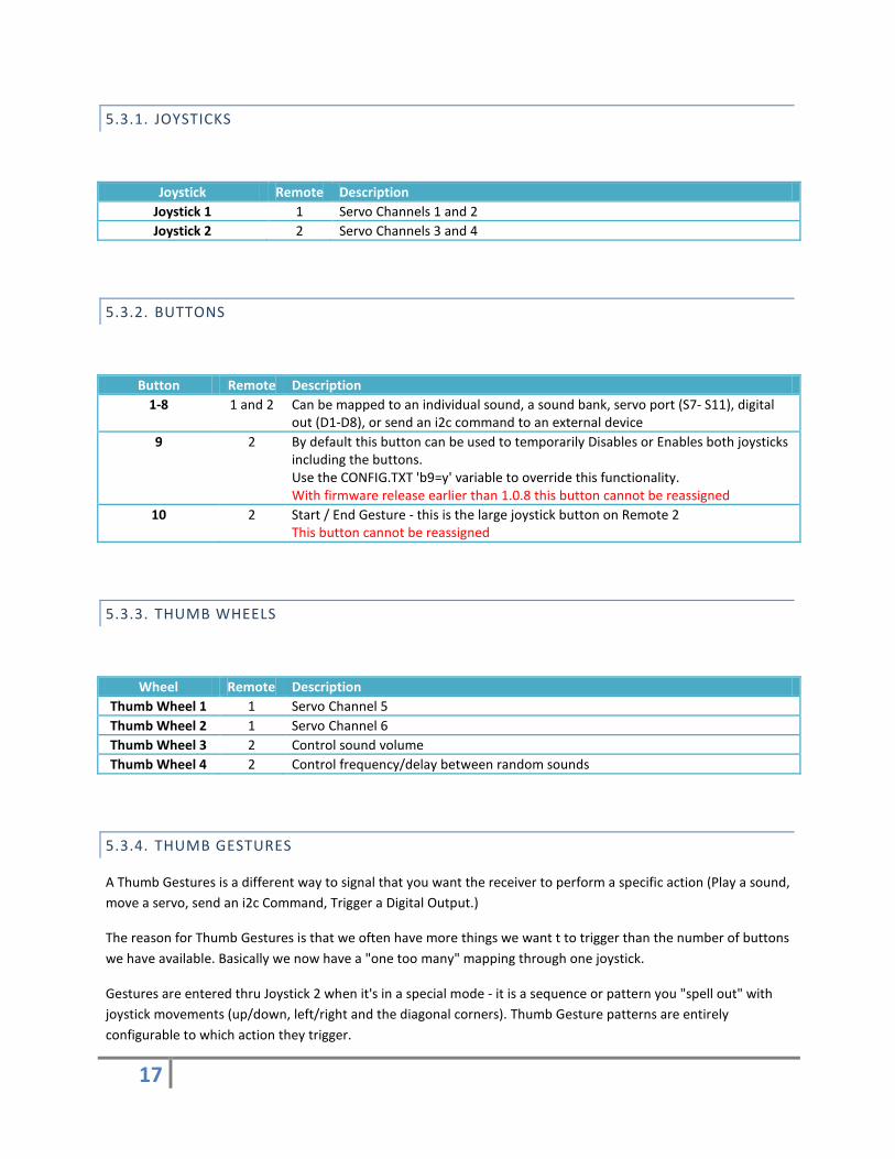
5.3.1. JOYSTICKS
Joystick Remote Description Joystick 1 1 Servo Channels 1 and 2 Joystick 2 2 Servo Channels 3 and 4
5.3.2. BUTTONS
Button Remote Description 1-8 1 and 2 Can be mapped to an individual sound, a sound bank, servo port (S7- S11), digital
out (D1-D8), or send an i2c command to an external device 9 2 By default this button can be used to temporarily Disables or Enables both joysticks
including the buttons. Use the CONFIG.TXT 'b9=y' variable to override this functionality. With firmware release earlier than 1.0.8 this button cannot be reassigned
10 2 Start / End Gesture - this is the large joystick button on Remote 2 This button cannot be reassigned
5.3.3. THUMB WHEELS
Wheel Remote Description Thumb Wheel 1 1 Servo Channel 5 Thumb Wheel 2 1 Servo Channel 6 Thumb Wheel 3 2 Control sound volume Thumb Wheel 4 2 Control frequency/delay between random sounds
5.3.4. THUMB GESTURES
A Thumb Gestures is a different way to signal that you want the receiver to perform a specific action (Play a sound, move a servo, send an i2c Command, Trigger a Digital Output.)
The reason for Thumb Gestures is that we often have more things we want t to trigger than the number of buttons we have available. Basically we now have a "one too many" mapping through one joystick.
Gestures are entered thru Joystick 2 when it's in a special mode - it is a sequence or pattern you "spell out" with joystick movements (up/down, left/right and the diagonal corners). Thumb Gesture patterns are entirely configurable to which action they trigger.

18
For example, to trigger a sound (but could be any of our 4 action types)
1. press Button 10 (Gesture Select) - Stealth Controller starts capturing gesture 2. wiggle Joystick 2 to input the predefined gesture pattern 3. press Button 10 (Gesture Select) - Stealth Controller stops capturing gesture 4. Stealth Controller translates your gesture to the predefined action. In this case play a sound
5.3.4.1. HOW THIS WORKS INTERNALLY
Each Thumb Gesture pattern is represented internally by a unique string of numbers. Those numbers map to one of 8 directions our joystick moves (up/down, left/right and the diagonal corners). Imagine the possible joystick positions as numbers on a grid, with 5 being the center position.
1 2 (UP)
3
4 (LEFT)
5 (CENTER)
6 (RIGHT)
7 8 (DOWN)
9
As your joystick moves from quadrant to quadrant the receiver adds the corresponding number to the pattern.
For example, moving the joystick left once, is "4", or moving the joystick twice left is "454".

19
5.3.4.2. INTERNAL LOGIC OF CAPTURING A GESTURE
Simplified logic when starting, capturing and stopping a Thumb Gesture
To initiate a gesture press Button 10. Then you move the stick to input the gesture. Either press Button 10 again to end/close the gesture, or wait 3 seconds and it will time out and perform the gesture action. If no gesture is made i.e. you didn't move the stick the action assigned to Gesture "5" is performed. It's recommended this is assigned to a random sound bank. If no valid gesture is found then nothing happens.
If you configure Gesture 5 as a sound, a simple double tap of the button will let you know if you're in a valid state and also act like an extra sound button.

20
You can also turn on Gesture Start Acknowledgment (a sound) by setting "ackon=y" in the configuration file, or performing the ackon gesture (if defined correctly in the configuration file.)
During gesture entry, servo channels 3 and 4 are returned to neutral, and restored when done.
5.3.4.3. THUMB GESTURES PATTERNS
There are two constraints when defining a Thumb Gesture pattern:
• Physically - the resolution of the joystick is small and if you're keeping the remote in your pocket it sometimes be hard to be accurate. Best to use simple patterns.
• Logically - internally we have an upper limit of 9 digits in our pattern string.
See section 6.7.9

21
Thumb Gestures on how to assign Thumb Gestures to specific actions.
5.3.4.4. AUTO CORRECT GESTURES
The auto parameter turns on auto correction of some common gestures, like the hard to hit corners. This is useful when learning gestures. But it does limit the number of gestures available. For example if you try and do a "LEFT TOP DIAGONAL" gesture which equals to "1", you can get there through several paths which may not be a direct line to the corner. You may actual do a UP LEFT ("21") instead of diagonal. Auto correct will convert this to a "1".
The system isn't perfect and it may fail to auto correct some patterns, especially performing double taps to the corners but it's should prove useful.
This feature is enabled by default.

22
5.3.4.5. EXAMPLE GESTURES
Pattern String Thumb Gesture / Joystick Movement 2 UP 4 LEFT 5 NOTHING / DEFAULT 6 RIGHT 8 DOWN 1 LEFT TOP DIAGONAL 3 RIGHT TOP DIAGONOL 7 LEFT BOTTOM DIAGONAL 9 RIGHT BOTTOM DIAGONAL
258 UP, CENTER, DOWN 852 DOWN, CENTER, UP 456 LEFT, CENTER, RIGHT 654 RIGHT, CENTER, LEFT 252 UP, CENTER, UP 454 LEFT, CENTER, LEFT 656 RIGHT, CENTER, RIGHT 858 DOWN, CENTER, DOWN
25252 or 45454 or 65656 or 85858
Easy Triples
2585258 or 8525852 Double Up/Downs 4565456 or 6545654 Double Left Rights
And you could have more complex combinations, but I'm sure you'll soon forget what's set to what.

23
5.4. MAINTENANCE AND SAFETY FEATURES
5.4.1. FAILSAFES
The Stealth Remotes can be used independently, and they both do not need to be turned on simultaneously for the system to function.
When you first turn on the remotes, you may see that Stealth Controllers status LEDs J1 and J2 blink off and on a few times. This is the XBEEs establishing a network. On 900MHz radios the network is established almost immediately, but can take 5-10 seconds on 2.4GHz radios.
Not critical but you could turn on the radios first before powering on your droid, that way the network is established in parallel with the Stealth Controller Receiver booting up. And you can turn the remotes on and off anytime during normal operation - it may just take a few seconds to re-establish the network.
How Stealth RC handles failsafes is the opposite to how most conventional RC setups do it, especially aircraft RC models - where failsafes can be a major issue when using them in robotics applications. Most will NOT returned servos to neutral but continue repeating the last instruction/action/channel they received. Result being a run-away droid. Stealth RC returns servos 1-6 back to neutral in a failsafe situation.
If the Stealth Controller does not received a signal from a remote for any reason within 1000 milliseconds, then its assigned servos are returned to a predefined neutral position and disengaged, this includes speed controllers.
In normal operation, the Stealth Remotes send data to the Stealth Controller every 100 milliseconds. This is adjustable by using an XBEE programmer. Increasing the send rate may improve joystick sensitivity, but at the expense of battery life. The default value will work fine for robotics applications.
5.4.2. SAFETY STRAP
Remotes have a slot on the bottom or side where you can insert a safety strap to secure the remote to your wrist.

24
5.4.3. CHARGING
Each remote is powered by small inexpensive 3.7V 380-400MAh rechargeable Li-Po battery. Depending on the XBEE radios installed and condition/age of the battery you should get around 4 hours of use on 900MHz radios and 6 hours on 2.4GHz radios.
These small Li-Po batteries typically do not have an under voltage protection circuit and can be damaged if left turned on and drained.
Device is charged through a micro USB port on back using the cable provided. This can be connected to an AC Adapter (not provided), computer USB port or External Booster Battery. Charge time will vary depending use, but should be about 2-3hrs from "empty".
When charging the yellow charging LED at the rear will come on, and turn off when done.

25
If you you're worried about being stuck in the field with a low battery, you may want to purchase an External USB Booster Battery.
They come in varying sizes and capacities.
Use a Y splitter cable to charge both remotes at the same time.

26
5.4.4. REPLACING INTERNAL BATTERIES
5.4.4.1. VERSION 1 REMOTES
The original V1 remotes use small, 3.7V 380-400mAh Li-Po rechargeable batteries. These can come in varying sizes and capacities, but the one's included will either measure 9mm x 25mm x 31mm or 8mm x 22mm x 37mm. The critical dimension is the width which can't exceed 25mm.
When replacing please pay close attention to the orientation/polarity of the plug.
To replace the battery:
1. Turn off power 2. Remove front screw 3. Open the case 4. Carefully lift out the circuit board 5. Disconnect old battery 6. Reconnect battery (pay close attention to polarity) 7. Insert circuit board 8. Don't forget buttons 9. Close case and replace screw (do not over tighten otherwise you may crack the case)
5.4.4.2. VERSION 2 REMOTES
Version 2 of the remotes have a slide off cover for easy access to the battery. Capacity is the same, 380-400mAH, but the battery has to be 8mm x 22mm x 39mm or smaller.
When replacing please pay close attention to the orientation/polarity of the plug.
27
6. STEALTH CONTROLLER RECEIVER
At the heart of the system is the Stealth Controller Receiver (SCR). It's configured via a series of jumpers, a configuration file stored on the USB Thumb Drive (CONFIG.TXT) and information stored in memory (EEPROM.)
Your servos and speed controllers plug in directly as you would with a conventional RC Receiver.
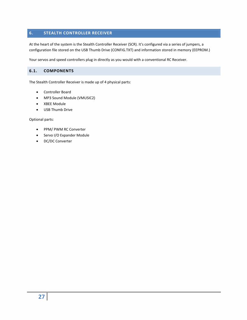
6.1. COMPONENTS
The Stealth Controller Receiver is made up of 4 physical parts:
• Controller Board • MP3 Sound Module (VMUSIC2) • XBEE Module • USB Thumb Drive
Optional parts:
• PPM/ PWM RC Converter • Servo I/O Expander Module • DC/DC Converter

28
6.2. STEALTH CONTROLLER RECEIVER CONNECTIONS
6.2.1. OVERVIEW
In a basic configuration many of the connections are not used. At a minimum the following would be connected in your droid:
• Power (PWR) • SERVOS: Drive Speed Controller (S1 and S2) + Dome Speed Controller (S4) • XBEE Module • MP3 VMUSIC2 Module + USB Thumb Drive
Please be careful on the orientation of all cables.
There have been several version of the main Stealth Controller board. Current version is 2.4. You can identify the board release by checking the label on the bottom of the board.
Connections are label on the board and detailed for each release on the next few pages.

29
6.2.1.1. REVISION 2.4
2.4 Board changes:
• TTL Console port is now a 6 pin header that's compatible with most FTDI cable/adapters. • XBEE status LEDs consolidated in one corner. • Power Terminal Blocks are larger.

30
6.2.1.2. REVISION 2.2
2.2 board changes/enhancements:
• More spacing between servo header pins • Additional status LEDs (S3 & S4) • ISCP moved to give more space for Servo header pins • XBEE TX LED • XBEE RSSI LED (signal strength) • More components are now surface mount for easier assembly

31
6.2.1.3. REVISION 2.1

32
6.2.2. POWER
Before connecting power to the Stealth Controller please read section 6.5.

33
Power Considerations.
DO NOT CONNECT +12VDC directly to the Stealth Controller. This is a +5VDC ONLY device.
6.2.3. PWR - EXTERNAL POWER FOR CONTROLLER
The PWR connector should be used to supply +5V to the main controller. You can use jumper JOIN5V to connect this supply to the internal servo +5V supply (but use with caution.)
Terminal Description - Ground + +5V
6.2.4. PWRHDR
Pin Description 1 Ground 2 +5V 3 Ground
PWR and PWRHDR are the same connected input, one is a screw terminal the other a convenient 3 pin jumper header.
6.2.5. SVOPWR
Terminal Description - Ground + +5V or +6V
SVOPWR supplies power to any servos connected, including the PPM Module and the +V pins on the Digital Out connections (if DPWR jumper is used/enabled). Typically SVOPWR is +5V but could be +6V to when driving larger servos.
Please be careful not to use the JOIN5V jumper if you plan on using +6V as this will damage the Stealth Controller.

34
6.2.6. SVOHDR- SERVO POWER SUPPLY
Pin Description 1 Ground 2 +5V 3 Ground
SVOPWR and SVOHDR are the same input, one is a screw terminal the other a convenient 3 pin jumper header.
6.2.7. JOIN5V - COMBINE CONTROLLER AND SERVO +5V SUPPLY
Pin Description 1 Controller +5V Supply 2 Servo +5 Supply
This jumper allows you to connect the Stealth Controllers +5V Supply with the Servos +5V Supply, mitigating the need for an extra +5V supply in some instances.
6.2.8. DPWR - ENABLE +5V SUPPLY TO DIGITAL OUT +5V PINS
Pin Description 1 Servo +5 Supply 2 Digital Out +5V Bus
This jumper allows you to connect the Servo +5V Supply to the Digital Out +5V pins.

35
6.2.9. SERVOS - SERVO OUT CONNECTIONS (S1 TO S12)
Pin Description S Servo PPM Signal (usually white or yellow wire) V +5V (usually red wire) G Ground (usually black or brown wire)
There are 12 servo connections, they provide PWM signals to drive your servos or speed controllers.
Servo PWM Output Channels are mapped to the Stealth Remotes as follows:
Servo Description Function 1 Remote 1 Joystick (Left/Right) Drive Motor Speed Controller 2 Remote 1 Joystick ( Up/Down) Drive Motor Speed Controller 3 Remote 2 Joystick ( Up/Down) Spare 4 Remote 2 Joystick (Left/Right) Dome Motor Speed Controller 5 Joystick 1 Thumbwheel 1 (Left) Spare 6 Joystick 1 Thumbwheel 2 (Right) Spare 7 Programmable * 8 Programmable * 9 Programmable *
10 Programmable * 11 Programmable * 12 Programmable *
* Servos S7 to S12 can be mapped to buttons or Thumb Gestures through setting parameters in the configuration file.
With the initial release, Servo Channels 1 and 2 are not mixed (Tank Mode.) Mixing should be done in the speed controller. See section 11.1 Speed Controllers for recommended and supported manufacturers.
6.2.10. DIGITAL OUT - DISCRETE DIGITAL OUTPUT CONNECTORS (D1 TO D8)
Pin Description S Signal / Digital Output V Not connected (+5V if DPWR jumper installed) G Ground
These outputs provide 8 +5V digital discrete outputs to connect external devices, e.g. lights, LEDs, small relays or solenoid. These outputs can't drive large devices but should drive a circuit to drive power hungry relays etc.
They can be configured/mapped to buttons, thumb gestures through setting parameters in the configuration file.

36
6.2.11. ANALOG I/O - DISCRETE DIGITAL OUTPUT CONNECTORS (A1 TO A2)
Pin Description S Analog Signal V Not connected (+5V if DPWR jumper installed) G Ground
A1 – Auto-Dome connection A2 - not used at this time.
6.2.12. I2C BUS
Pin Description V +5V G Ground
SCL i2c Clock Signal SDA I2c Data Signal
Used to connect Servo Expander Modules and other i2c devices.
6.2.13. PPM IN - PPM MODULE CONNECTOR
Pin Description 1 Signal 2 +5V (from Servo Bus) 3 Ground
This is the connection for the optional PPM/PWM Converter Module.

37
6.2.14. XBEE - XBEE RADIO MODULE TTL SERIAL CONNECTION
Pin Description 1 RX 2 TX 3 +5V 4 Ground
The XBEE Radio can either be plugged in directly to the XBEE socket, or to an external XBEE adapter via the 4 pin header. See section 6.3 XBEE Radio Module for more details.
6.2.15. SER - TTL SERIAL CONNECTION
TTL serial connection for the debug console and Command Line Interface (CLI). TTL levels.
Board revision 2.2 and lower:
Pin Description 1 TX 2 RX 3 Ground
Board revision 2.4 and above:
Pin Description 1 DTR (reset pin, can be disabled by unsoldering jumper SJ1) 2 TX 3 RX 4 5V (can be disabled by unsoldering jumper SJ2) 5 Not Connected 6 Ground
6.2.16. AUX - AUXILIARY TTL SERIAL CONNECTION
Pin Description 1 TX 2 RX 3 Ground
This connector is used to connect 3rd party devices. On firmware release 1.0.8 on this is enabled and can be configured to transmit serial text in sync with actions. For example to trigger JEDI or Teeces logics to perform predefined routines. See section 6.7 for configuration options.

38
6.2.17. VMUSIC2 - MP3 MODULE CONNECTOR
Pin Description 1 Ground 2 CTS - not connected 3 +5V 4 VMUSIC2 TX 5 VMUSIC 2 RX 6 RTS - connected to Ground 7 No Pin / Key 8 RI - not connected
6.2.18. RCSEL- RC MODE SELECT JUMPER/HEADER
Pin Description 1 Ground 2 RC mode select
When enabled, control input is switched to run the system from your conventional RC remotes connected to the PPM Converter Module (PPMIN.)
It's recommended you use header/jumper wire with a panel mount toggle switch on one end and mount it somewhere convenient and easily accessible.

39
6.2.19. SEL2 - HEADER
On firmware releases 1.0.8 on, when this header input is enabled (with a jumper or switch) the Stealth Receiver Controller can mimics a JEDI RC Receiver and can be used as a direct replacement for it. Output on the Aux Serial port (AUX) should be connect to the JEDI Controller RC Receiver port.
Be careful of pin assigments, on the JEDI Controller the center pin is 5V and should not be connected. Please see suplemental documentation for wiring example.
Pin Description 1 Ground 2 JEDI mode select
6.2.20. STATUS - STATUS HEADER BREAKOUT
Pin Description 1 Ground 2 J1 3 J2 4 RC 5 S1 6 S2
These pass thru the status LED signals to an optional LED module to mount elsewhere in your droid. See section 6.4 Status LEDs.
6.2.21. ISP- ICSP PROGRAMMING HEADER
Pin Description 1 MISO 2 +5V/VCC 3 SCK 4 MOSI 5 RESET 6 GND
AVR/ATMEL ICSP Programming Header. Pin one is marked on the board with a bar (top left.)

40
6.3. XBEE RADIO MODULE
6.3.1. CONNECTING
The XBEE Radio is normally plugged directly in to the Stealth Controller Receiver board, but it can be used in a 3rd party XBEE Adapter board connect via a cable allow placement of the antenna in a different location.
Typically XBEE Adapters have RX, TX, +5V and Ground pins at a minimum. In most case we only requires the TX, +5V and Ground be used/connected, so a simple 3-wire jumper cable could be used if you can't find a 4-pin jumper cable. Please be careful of orientation of the cable as to not connect the +5V to an incorrect pin.
6.3.2. EXAMPLE XBEE ADAPTERS
Adafruit Sparkfun
www.adafruit.com/products/126 www.sparkfun.com/products/11373

41
6.4. STATUS LEDS
There are several groups of status LEDs on board; the main Status LED near the power connections, XBEE Status LEDs and 2 power LEDs.
6.4.1. POWER
Label LED Color Description PWR Red Receiver Power - On when power applied to PWR
SVOPWR Red Servo Power - On when power applied to SVOPWR
6.4.2. XBEE STATUS LEDS
These LEDs represent the onboard status of the XBEE radio and may (will) blink independently of the current running stat of the main Stealth processor and it's status LEDs (J1, J2, S1 etc). For example as soon as the XBEE radios lock on to each other you will see one of the Red LEDs start blinking as it receives data from the Stealth Remote.
Label LED Color Description XB-RX Red XBEE Radio Module Data Receive Activity (RX) XB-TX Red XBEE Radio Module Data Transmit Activity (TX) - Only on boards 2.2+ RSSI Green XBEE Radio RSSI Indicator - radio Signal strength. This is supposed to be
brighter/dimmer depending on quality of signal. Only on boards 2.2+
6.4.3. STATUS
Label LED Color Description J1 Red On when signal is being received from Remote 1 J2 Blue On when signal is being received from Remote 2 RC Yellow RC Radio mode enabled (RCSEL):
• On constantly when signal being received from PPM Converter Module. • Blinking means RC mode selected but no PPM signal detected/connected. Note:
Failsafes for PPM Module are handled in your RC Receiver. S1 Green Main Receiver Status:
• On constantly is normal after initialization/startup sequence. • Slow blinking means running okay, but didn't read configuration from VMUISC2
(Running on parameters from EEPROM.) • Rapid blinking means we failed to load either CONFIG.XT or the EEPROM
parameters. We're operating on a very basic configuration and at this point waiting for input from the Command Line Interface. Joysticks will not work in this
42
mode unless you manually enter the XBEE addresses.
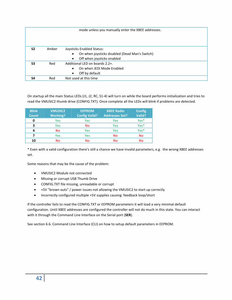
S2 Amber Joysticks Enabled Status: • On when joysticks disabled (Dead Man's Switch) • Off when joysticks enabled
S3 Red Additional LED on boards 2.2+. • On when JEDI Mode Enabled • Off by default
S4 Red Not used at this time
On startup all the main Status LEDs (J1, J2, RC, S1-4) will turn on while the board performs initialization and tries to read the VMUSIC2 thumb drive (CONFIG.TXT). Once complete all the LEDs will blink if problems are detected.
Blink Count
VMUSIC2 Working?
EEPROM Config Valid?
XBEE Radio Addresses Set?
Config Valid?
0 Yes Yes Yes Yes* 3 Yes No Yes Yes* 4 No Yes Yes Yes* 7 Yes Yes No No
10 No No No No
* Even with a valid configuration there's still a chance we have invalid parameters, e.g. the wrong XBEE addresses set.
Some reasons that may be the cause of the problem:
• VMUSIC2 Module not connected • Missing or corrupt USB Thumb Drive • CONFIG.TXT file missing, unreadable or corrupt • +5V "brown outs" / power issues not allowing the VMUSIC2 to start up correctly • Incorrectly configured multiple +5V supplies causing feedback loop/short
If the controller fails to read the CONFIG.TXT or EEPROM parameters it will load a very minimal default configuration. Until XBEE addresses are configured the controller will not do much in this state. You can interact with it through the Command Line Interface on the Serial port (SER).
See section 6.6. Command Line Interface (CLI) on how to setup default parameters in EEPROM.

43
The 5 status LED can also be broken out on to an optional status board which you can located elsewhere in your robot for easy viewing.

44
6.5. POWER CONSIDERATIONS
There are two power buses on the Stealth Controller Receiver:
• The primary one, PWR (+5V), for the micro-controller, MP3 and XBEE Modules. • A secondary bus, SVOPWR, to power Servos, Digital Outputs and the PPM Module/RC Receiver. This can
either be +5V or +6V, and the connection is optional.
You can either connect your +5V supply using regular wire to the PWR terminal block (up to 16 AWG) - - a +5V DC Converter is recommended (pictured.)
Or using a 2 or 3 pin jumper wire to the PWRHDR header behind the PWR terminal block

45
If you plan on connecting servos (not speed controllers) and/or the PPM Module, then a +5V supply should be connected to SVOPWR (see section 0.)
OR this can be shared with PWR by using JOIN5V in most instances.
Do not install the JOIN5V jumper if you have a secondary power source connected to SVOPWR.
Most, if not all, Speed Controllers do not require power on the servo cables center wire to operate (normally colored red). In fact most Speed Controllers include a built in Battery Elimination Circuits (BEC) to power a conventional RC Receiver thru the red wire center wire.
You should not connect this +5V (red) wire to the servo bus. It could damage the Stealth Controller, any connected DC Converter or other Speed Controllers.
The PPM Module (and tethered RC receiver) is powered from the Servo +5V/+6V line (center pin). Please check if your RC Receiver can operate at +6V if you plan on powering this bus with a +6V supply.
It's tempting to try and use the Speed Controller's BEC to power servos and/or the PPM Module/RC Receiver, but it will probably not provide enough amperage and will could cause brown out issues.
Don't try and power the entire setup from a cheap power suppy, Speed Controller BEC or a simple "7805" regulator. The BEC or 7805 will probably overheat and cause brown out issues.

46
6.6. COMMAND LINE INTERFACE (CLI)
The Stealth Controller Receiver Controller has a Console or Command Line Interface (CLI) via a TTL Serial port SER. It operates at 57,600 Baud, 8N1 and you will need a TTL level serial adapter/cable to access it.
On Stealth Controller boards 2.2 and up, there's an option to access the console wirelessly via the Pocket Remotes XBEE FTDI USB / Serial interface.
The CLI is used to interact with the controller to:
• View/set parameters which are used as backup when a CONFIG.TXT file can't be found/read • View live servo digital outputs values • Perform debug/troubleshooting • Trigger commands / actions via the command line
6.6.1. CONNECTING TO THE CONSOLE VIA HARDWIRE
On board versions 2.4 and up you can connect a FTDI cable or adapter directly into the 6 pin header.

47
On older boards (2.2 and lower), and depending on your serial port/device, you may need to fashion a cable to break out the 3 pins in the correct order (TX, RX and GND).
Here's an example using the Sparkfun USB FTDI Serial Adapter/Breakout (DEV-09716).
Some adapters have male pins, others a female socket. We recommend the one's with the female socket as you can also use it to program the Arduino Pro Mini's on the Servo Expander Modules.

48
Or using the more traditional FTDI Cable

49
6.6.2. CONNECTING TO THE CONSOLE VIA XBEE / WIRELESS
Each Pocket Remote is enabled as a USB Serial Device (FTDI). You should be able to connect it to your computer (or even a compatible smartphone) and it should show up as a USB COM Port. If you use a terminal application, as with the wired connection, you should be able to interact with the Controller remotely.
Local echoing is not enabled by default, but as you type the characters are being send to the Controller and interpreted.
Once connected, if you hit enter a few times then type 'xce' at the console/terminal echoing is enabled and if you hit enter you will get a command prompt.
Because bandwidth limitations, it's not normally recommend to echo the command console output to the remote host/terminal during normal operation.
In theory you could also wire up the real console port to an additional XBEE or WiFly Radio, and use 3rd party application on your phone (or otherwise) to trigger commands remotely.
6.6.3. ANDROID CONNECTVITY
Most new Android phones (3.X or greater) support external USB devices. Using a USB OTG Cable you should be able to connect to the FTDI chip, and with the right terminal application interact with the remote console.
If you plan on connecting your remotes to your phone, note that the Pocket Remotes WILL charge from your phone.
6.6.4. SERIAL TERMINAL SOFTWARE
There are many free terminal software application, and it's really a personal choice and will also depend on if you're on a PC or Mac. Putty (www.putty.org) is one example; it's a very old application but works well.
Some functions in the CLI use VT100 escape sequences to paint the screen, for example the live Servo/Output monitor.

50
6.6.5. EXAMPLE OUTPUT

51
6.6.6. COMMANDS
You should get a ">" prompt if you hit enter.
Command Description h/? Display help message
v Display version information d Display current running configuration r Turn random sounds on/off
$nn Play Sound from Sound Bank nn $nnmm Play Sound mm from Sound Bank nn
s Servo Command. Set Servo position/Speed. s{nn},{mmm},{ooo}. nn=Servo # (06-12), mmm=position (000-180), ooo=speed (001-100)
o Digital Out Command. o{nn},{m}. nn=Digital Out # (01-08), m=1 (on), m=0 (off), 2=toggle, 3=momentary/blink/blip
a Output string to Aux Serial. a[string]
i i2c Command i{nnn},{mmm}. nnn=Dest Addr, mmm=Cmd
axxxxx Aux String Command. x Display XBEE radio addresses
x{[n]=[hhhhhhhh]} Display/Set XBEE address. Where n=1 or 2, hhhhhhhh=Hex address c Show configuration information stored in EEPROM (don't load) l Load configuration setting from EEPROM (XBEE addresses and RC/Servo parameters only)
w Write configuration setting to EEPROM (XBEE addresses and RC/Servo parameters only) m Display live Servo and Digital Out values - requires VT100 compatible terminal. Entering s
again will turn the monitor screen off. xcc Toggle Remote XBEE Command option - allow you to send commands via the XBEE USB Serial
Interface, as if you were hardwired to the Controllers Console. Setting is permanent and survives reboot.
xce Toggle XBEE Console Echo (mirror hardware console output). Setting is temporary and doesn't not survive reboot.
xcb Toggle XBEE Console Broadcast. Should only be enabled for 900MHZ XBEE radios. dump Show content of CONFIG.TXT. Doesn't always work.
* Enter a configuration command as if it came from CONFIG.TXT
Useful for temporarily flipping servo channel parameters like direction without changing CONFIG.TXT. Or configuring the Stealth Controller without a VMUSIC2 Module where parameters are saved/loaded from EEPROM. Not all CONFIG.TXT entries are appropriate. Valid entries are: "s", "maxpulse", "minpulse", "xbr", "xbl", "mindelay", "maxdelay", "rcchn", "rndon" For Examples: *s=1,0,180,89,3,-3,100,1 *xbr=409AB010 *maxdelay=240
autod=N set auto-dome mode to N, where N=1,2,3. Normal/Home/Seek. tmpvol=NNN,MM Set temporary volume from 000 to 100, for 01-99 seconds. tmprnd=NN Temporarily stop random sounds from 01-99 seconds. If 00 then turn off random sounds
permanently.

52
6.7. CONFIGURATION
The Stealth Controller Receiver first loads configuration values from the EEPROM, and then reads the CONFIG.TXT (file located in the top directory of the USB Thumb Drive.) Values read from the file will temporarily overwrite any set from the EEPROM configuration.
6.7.1. EEPROM CONFIG
A minimal set of values can be stored in the EEPROM, either to speed boot-up or as a fall back configuration in case the VMUSIC2 module / Flash Drive is not connected or fails. Either way it's recommended to keep the EEPROM current.
Only two sets of information is really stored:
• XBEE Radio Configuration (Address and calibration data) • Servo/Channel Parameters
These values can be set/loaded/refresh from the command line interface, or copied/set from the current CONFIG.TXT file, either on boot-up or from the command line interface.
Not button assignments, actions, gestures etc are stored in EEPROM.

53
6.7.2. MANUAL REFRESH OF EEPROM
USE WITH CAUTION
Typically you would configure the controller thru CONFIG.TXT or the command line interface. But we've provision a special procedure in case the EEPROM values are miss-set or lost during firmware upgrades, and you don't have access to computer to edit CONFIG.TXT or a serial device to perform the operation thru the Command Line Interface.
The three XBEE radios are already bound together and share the same encryption keys. This can't be easily changed. However, you can rebind the radios (address/calibration) to your Stealth Controller board.
Note: Any CONFIG.TXT configuration values will still overwrite setting loaded from EEPROM on bootup.
6.7.3. "BIND" PROCEDURE
1. Power Off everything including Pocket Remotes 2. If you have a Status LED Board, unplug it 3. Connect a jumper wire between Status Header Pin S1 and S2 (note, on some boards they were both miss-
labelled as S2 and S2, instead of S1 and S2.) 4. Power On the Stealth Controller (but not the remotes yet) 5. S1 & S2 status LEDs should be illuminated (orange/green) 6. J1 status LED (red) will blink until the first Pocket Remote is turned on 7. Turn on first (RIGHT/RED) Pocket Remote 8. Once the Pocket Remote is recognized the J1 status LED will be on (not blinking) 9. J2 status LED (blue) should start blinking 10. Turn on the second (LEFT/BLUE) Pocket Remote 11. J2 status LED will be on (not blinking) 12. Within a second the J1 and J2 will start to blink back and forth (getting progressively faster.) 13. We're now in calibration mode 14. Wiggle both joysticks in full circles, making sure you reach the extreme positions. 15. After 10 seconds, the J1 and J2 status LEDs should go off. 16. One a a time, J1 and J2 should then blink a count of how many points the joysticks were adjusted
(sometimes this could be zero, but may be 5-10 times.) 17. The unique address for the remotes and the calibration data is now copied to EEPROM 18. At this point the Controller will continue its boot process, ready to use 19. However, it's best to power down and remove the jumper wire

54
6.7.4. CONFIG FILE (CONFIG.TXT)
The file is made up of 6 sections, General Parameters, Sound Banks, Buttons, Thumb Gestures, Auto-Dome and Servo Channels
Due to memory constraints minimal validation is done while reading the configuration file. Parameters are case sensitive and are all lower case. Extra spaces are not removed or recognized and will most likely make the line invalid (basically don't use spaces.)
Comments are supported (line starting with #) in the file, but the more text you have the more time the controller will take to start up.
Max length of a line is 60 characters.

55
6.7.5. GENERAL PARAMETERS
General for of the parameter is parameter=value
Parameter Range/Valid Values
Example/ Typical
Description
volume 0-100 50 Initial volume. In most instances only the startup sound will play at this volume
startup y/n y Play startup.mp3 when the system boots rndon y/n y Play random sounds, can be disabled/enabled after boot by using the
rnd gesture rnd Gesture 3 Gesture assigned to turn random sounds on or off
ackon y/n n Play acknowledgment sound (ack.mp3 in root directory) when triggering start of gesture. Useful when learning to use Thumb Gestures
ack Gesture 222 Gesture assigned to turn acknowledge gesture sound on or off mindelay 0-1000 60 Min delay before playing next random sound (seconds) maxdelay 0-1000 120 Max delay before playing new random sound (seconds)
xbr HEX 419998E4 Right XBEE's unique serial number (lower address in hex) xbl HEX 419959F3 Left XBEE's unique serial number (lower address in hex) rvr 990-1023 1023 Adjust Right Joystick Analog "Reference Voltage" / calibration value. rvl 990-1023 1023 Adjust Left Joystick Analog "Reference Voltage" / calibration value.
mix12 y/n N Mix/Tank Mode. Mix servo channels 1 and 2 (not supported yet.) minpulse 1000 Minimum pulse width for all servo outs (internal default 1000) maxpulse 2000 Maximum pulse width for all servo outs (internal default 2000)
rcchn 6/8 6 How many channels does the RC radio have rcd 1-50 30 RC Radio deadband (all channels) - this is in milliseconds rcj 1-40 5 RC Radio jitter adjust - this is in milliseconds. Also reduces joystick
accuracy/sensitivity. myi2c 0-100 1 Stealth Controller Receiver's unique i2c address
auxbaud 9600 Baud Rate of the Auxiliary Serial Output , typically 9600, 19200, 57600 etc.
auxinit String sent to Auxiliary Serial Output on startup/boot auxdelim : Delimit character use to split up single aux strings into multiple lines
that are sent as one block. Default is 13, but can be any ASCII character (Decimal value)
auxeol 13 Character denoting EOL (end of line) sent between chucks of text in the aux serial output and the end of the block. Default is 13, but can be any ASCII character (Decimal value)
mem y/n N Write current thumb drive config to EEPROM on bootup. Do NOT keep this set to "y" permanently.
auto y/n N Auto correct common gesture. e.g. corners are hard to hit, so we autocorrect miss-gestures. Downside limits number of available gestures. Default=yes.
b9 y/n N Allow action assignment to the special button 9 which by default is the Dead-Man Switch to disable/enable the joysticks. Assigning a value of 'y' will allow you to use it in the same way as any other button.
xcmd y Enable commands via the Remote XBEE Console
fst 1000-3000 1500 Adjust the filesafe timeout. You wouldn’t normally adjust this.

56
6.7.6. SOUND BANKS
You can configure up to 20 sound banks. Each sound bank is stored in its own(named) directory, and can have up to 100 files. If there are multiple files in the directory, then a random one is selected by default. If there's a single file in the directory that file is used.
Playback is stopped when you trigger another sound or the file ends.
If random sounds are enabled (rndon=y), files from sound banks 1,2, and 3 are randomly used (favoring banks 1 and 2, typically groups of chatty and generic sounds.)
When you perform the gesture to enable/disable random sounds (set by rnd) your robot will now acknowledge which mode it’s in (random on or off) by playing MP3 files 1.mp3 and 2.mp3. By default 1.mp3 is one pip sound (for random off) and 2.mp3 is two pips (for random on).
Delay between random sounds is governed by mindelay and maxdelay (in seconds). You can dynamically adjust the delay with Remote 2's right Thumb Wheel. This increases or decreases the maximum delay.
If a specific sound is triggered while random sounds are enabled, random sounds will be suspended until the specific sound is completed. Random sounds will then resume.
Sound banks have a unique number (1-20) and are sequentially assigned based on the order read in the configuration file. In the example below, "gen" is sound bank 1, "whistle" is sound bank 4.
By default sound banks with more than one file are played in random order, the system should not repeat a random sound if it's been played within the last 4 plays. Additional "s" value signifies sequential play of sound bank.
Parameter Option/Value Format Examples Description sb [directory
name],[number of files],{ [random or sequential order]}
sb=gen,46 sb=chat, 20,s sb=vader,1 sb=scream,5,r sb=whistle,3,s sb=leia,1
Sound Bank "gen", 46 files, random play (default) Sound Bank "chat", 20 files, sequential play Sound Bank "Vader", 1 file Sound Bank "scream", 5 files, random play Sound Bank "whistle", 3 files, sequential play

57
6.7.7. AUXILIARY STRING OUTPUT
Starting with firmware 1.0.8, we can now define up to 10 strings that can be sent to the auxiliary serial port when we perform a specific action/function.
Auxiliary String are assigned a number based on the order they appear in the config.txt file. And can be optionally assigned to actions by specifying this number at the end of an action.
One example of its use it to trigger external events on JEDI or Teeces Logics.
Parameter Option/Value Format
Examples Description
a [string] a= ABCDEF:GHIJKLM:NOPQRSTU:VWXYZ a=xyz123
Aux String containing 4 lines of output. Delimited by ":" Single line of auxiliary output
6.7.8. BUTTONS
There are a total of 8 user definable buttons (1-8) that can be assigned to perform actions. Each action is of one of 4 Types and is the second parameter passed in the configuration line:
Type Action Format Examples Description 1 Sound b=[button #],1, [sound bank#],{[aux
#} b=1,1,1 b=2,1,3,5
Button 1, Sound Action, Sound Bank 1 Button 2, Sound Action, Sound Bank 3, Aux String 5
2 Servo b=[button #],2,[servo #],[On Position], {[aux #}
b=2,2,7,180 Button 2, Servo Action, Servo #7, On Position of 180
3 Digital Out b=[button #],3,[digital out #], [out-type] ,{[aux #}
b=6,3,1,0 Button 6, Digital Out Action, Digital Out #1, Normally Open
4 i2c Command b=[button #],4,[target i2c address],[command] ,{[aux #}
b=8,4,99,1 b=5,4,98,2,3
Button 8, i2c Action, i2c target=99, command=1 Button 5, i2c Action, i2c target=98, command=2, Aux String 3

58
6.7.9. THUMB GESTURES
Thumb Gesture configuration is very similar to buttons. Each one is allocated an action, and is of one four Types:
Type Action Format Examples Description 1 Sound g=[gesture code],1,[Sound Bank
#],{[aux #} g=66,1,1 g=44,1,3,2
Gesture "66", Sound Action, Sound Bank 1 Gesture "44", Sound Action, Sound Bank 3, Aux String 2
2 Servo g=[gesture code],2,[servo #],[On Position] ,{[aux #}
g=2,2,7,180 Gesture "2", Servo Action, Servo 7, On Position of 180
3 Digital Out g=[gesture code],3,[digital out #],[out-type] ,{[aux #}
g=4,3,1,2 g=7,3,4,2,1
Gesture "4", Digital Out Action, Digital Out 1, Momentary Gesture "7", Digital Out Action, Digital Out 4, Momentary, Aux String 1
4 i2c Command
g=[gesture code],4,[target i2c address],[command] ,{[aux #}
g=88,4,99,1 Gesture "88", i2c Action, i2c target=99, command=1
See section 5.3.4.3. Thumb Gestures Patterns.
6.7.10. COMMON NOTES ON GESTURES AND BUTTONS
Servos are always in the neutral/center position on startup (defined in the Servo section of the configuration file.)
Digital Outputs can be one of 3 types:
Output Type Value Normally Open 0
Normally Closed 1 Momentary 2
Digital Outs are always set to OFF initially on power on. It's the nature of the Micro-Controller and how it handles the output pins. We also have to first read the configuration file to determine what we want the outputs to do. If any are set to Normally Closed (NC) in the configuration, then they will be set to ON after reading the file. It's probably not a good idea to use the Normally Closed output type unless it's for something non-critical like a status LED.
Digital Outs and Servos objects can be shared between Buttons and Gestures. It's not a good idea to have different meanings or values for the same object. e.g. A digital out being defined as normally open for one buttons, but the gesture redefines it as a momentary output. Whichever one is defined last in the configuration file will override the value of the former, and the button will also trigger a momentary action.
Maximum addressable i2c devices is 5. Each device has to have a unique ID.

59
6.7.11. SERVOS AND CHANNELS
Parameters only apply to servos/channels when using Stealth Pocket Remotes. For RC Mode, radio channels 1, 2, 3 and 4 values are passed straight thru to the corresponding Stealth Receiver Servo Channels (S1-S4.)
In this section of the configuration file we can set the characteristics of our servos/channels.
Starting with release 1.0.10 of the firmware you can now set min/max pulse width on a per channel bases, but it's optional.
Structure Examples Description s=[servo #],[min],[max],[neutral],
[deadband],[trim],[speed],[reversed], { [minpulse, maxpulse] }
s=1,0,180,89,3,-3,100,0
Servo 1, min=0, max=180, Center/Neutral=89, Deadband=3 around center, Trim = -3, speed=fastest, not reversed
s=2,10,170,90,30,10,1 Servo 2, min=10, max=170, Center/Neutral=90, Deadband=30 around center, Trim =0, speed=slow, direction reversed
s=1,0,180,90,4,0,50,0,800,2200
This sets for channel 1 a min pulse of 800us and a max of 2200us.
Typically servos rotation is defined in degrees around a center point. From 0 to 180 degrees, with 89 or 90 being the center position, 0 being one extreme and 180 being the other. Physically your servo may only turn in either direction less than 90 degrees, but internally we still define the extreme positions (min and max) as 0 and 180.
Speed Controller behave in a similar way, with 0 to 180 defining the "speed" of the motor rather than position.
When using a mixed setup that includes a traditional RC Remote- Match your Servo Reverse and Trim Parameters to your RC radio settings.
You can use these parameters to limit or change the characteristics of the servos and speed controller.
What Range or Values
Description
min 0 to 88 Min position you want the servo to reach. Always has to be less than servo max.
max 90 to180 Max position you want the servo to reach. Always has to be greater than servo min. You can flip min and max, use reverse parameter for that.
neutral 0 to 180 Center or Neutral position of the servo deadband 0-89 Number of degrees around center that will still register as center. Basically
override the current joystick or thumbwheel value with the neutral position if it falls within our deadband. This can be used to reduce the sensitivity of the joysticks. Another use is to set a deadband on the side thumbwheels so you don't have to return it to dead center to return the servo to center.
trim -90 to 90 Logically shift the center position of the servo/joystick either left or right. Typically this is not used, or if it is, is only set to a few degrees in one direction. e.g. -1, -2, 1 or 2.
speed 1 to 100 How fast the servo will move or accelerate, 1 = Slowest, 100=Fastest This parameter is useful if you're speed controller doesn't offer adjustable

60
acceleration/breaking curves. A good value to start with for the drive speed controller would be 30-40
reversed 0,1 Flip the direction of the servo, 0=normal, 1=reversed minpulse <=1000 Optional value. Sets min pulse for servo channel on startup. maxpulse >=2000 Optional value. Sets max pulse for servo channel on startup.
By default the min/max pulse width is 1000us to 2000us. If you don’t need to change these then your servo entry in config.txt may look like this:
s=1,0,180,90,4,0,50,0
If you need to change the pulse width you’d append two new values to the end of the line. For example
s=1,0,180,90,4,0,50,0,800,2200
This sets for channel 1 a min pulse of 800us and a max of 2200us.
Again, you don’t need to change or add these values. If you don’t the defaults are used (1000-2000).

61
6.7.12. AUTO-DOME PARAMETERS
Parameter Range/Valid Values
Example/ Typical
Default Description
domegest 8 None Dome gesture to switch auto-dome modes. domehome 0-360 270 270 Dome home position. Typically a value between 180-
360, but depends on relation of stylus to front of dome.
domemode 1-3 1 1 Initial startup dome mode. 1=normal/off, 2=home, 3=random seeks
domemindelay 1-255 1 1 Set min delay between random seeks (seconds). Controlled by right joystick, Pot 2.
domemaxdelay 1-255 20 8 Set min delay between random seeks (seconds). Controlled by the right/red joysticks right thumbwheel.
domeoffset 1-90 0 0 Adjust the reading of the stylus position relative to zero.
domeseekr 1-180 50 80 Number of degrees right of “Home” to seek. Typically less than 90.
domeseekl 1-180 50 80 Number of degrees left of “Home” to seek. Typically less than 90.
domefudge 1-20 5 5 A fudge factor on how close we need to be to target. Are we close enough?
domespeedhome 1-100 40 40 Speed we try to move to home position. Higher the number the faster.
domespeedseek 1-100 30 30 Speed we try to move to seek position. Higher the number the faster.
domespmin 42 SoftPot Analog Min reading. Should not be changed. A calibration procedure will be added later.
domespmax 935 SoftPot Analog Max reading. Should not be changed. A calibration procedure will be added later.

62
6.7.13. EXAMPLE CONFIG.TXT #START xbr=408C27B9 xbl=408C27B8 s=1,0,180,90,5,0,30,0 s=2,0,180,90,5,0,30,0 s=3,0,180,90,1,-1,40,0 s=4,0,180,90,1,0,40,0 s=5,0,180,90,10,0,50,0 s=6,0,180,90,10,0,50,0 s=7,0,180,89,0,0,100,0 s=8,0,180,89,0,0,100,0 volume=50 startup=y rndon=y ackon=n mindelay=10 maxdelay=120 rcchn=6 myi2c=0 sb=gen,16 sb=chat,22 sb=sad,11 sb=rasb,1 sb=whis,12 sb=scream,4 sb=warn,2 sb=short,1 sb=leia,1 sb=vader,1 sb=sw,1 sb=dance,2 sb=cant,1 b=1,1,3 b=2,1,4 b=3,1,7 b=4,1,8 b=5,1,2 b=6,1,5 b=7,1,6 b=8,1,2 rnd=3 ack=252 g=5,1,1 g=6,1,10 g=4,1,9 #END

63
6.8. MP3 MODULE (VMUSIC2)
Connect the VMUSIC2 module using the 7 pin multi-colored jumper wire. The plug is keyed and will only go one way.
On power-up the green LED on the VMUSIC2 module will blink as it reads the configuration file, and when it plays sounds.
6.8.1. LINE OUT / AUDIO SETUP
Connect your amplifier to the VMUSIC2 Module via the 3.5mm jack. A Ground Loop Isolator is highly recommended. For testing you could also use earphones.
Note: Depending on the amplifier you use, it's recommended that a Ground Loop Isolator is installed between the VMUSIC2 module and the amplifier to eliminate any feedback or possible damage to the VMUSIC2 module.

64
6.8.2. USB FLASH DRIVE / THUMB DRIVE
A standard USB thumb drive can be used, formatted as FAT32.
6.8.3. AUDIO FILES AND FORMAT
All sound files should be encoded as MP3.
See VMUSIC2 Reference Guide for details
http://www.ftdichip.com/Products/Modules/ApplicationModules.htm

65
6.9. INCOMING I2C COMMANDS
The receiver recognizes incoming commands on the i2c bus.
In firmware release >= 1.0.10, how we handle incoming i2c request/commands to the main Stealth Controller Receiver has changed. Previously all we could do is make request to play a sound. Now we can send full commands as if we were typing at the command line interface. This allows us to control things like volume, temporarily disable random sounds or even set servo values.
There’s a new Arduino function you’ll need to include to send commands (see below).
In the old Arduino code we sent a series to i2c write commands. Now we use a single line.
For example we now can do this:
sendI2Ccmd("tmpvol=100,08"); // set temp volume to max for 8 seconds sendI2Ccmd("tmprnd=60"); // temp delay random sounds by 60 seconds sendI2Ccmd("$07"); // Play sound bank 7
You can assign/change the receivers unique i2c address with the myi2c parameter in the configuration file. See
//--------------------------------------------------------------------- // New i2c Command for Arduino Servo Expanders //---------------------------------------------------------------------
void sendI2Ccmd(String cmd) {
sum=0;
Wire.beginTransmission(DESTI2C);
for (int i=0;i<cmd.length();i++) { Wire.write(cmd[i]); sum+=byte(cmd[i]); }
Wire.write(sum); Wire.endTransmission();
}

66
7. AUTO-DOME
If you’re dome base plate attaches to your dome, and auto-dome is enabled/turned on please be very very careful when removing the dome. When the stylus loses contact with the softpot it will return zero and if that’s not the home position your dome will spin and spin, potentially ripping out cables.
Auto-Dome connects to “A1” port. Inner most pin is the “Signal”, outer is ground and center is power.
You will need a jumper on “DPWR” which connects the Data/Analog power rail to the Servo power rail.
SVOPWR has to be 5V (you can’t run direct connect servos at 6V as we share the line with the SoftPot which is strictly 5V only.)
SVOPWR has to either be connected to PWR with the JOIN5V or be powered separately. BUT it has to be 5VDC. No exceptions.
There are a number of new config.txt parameters to govern how the auto-dome operates. Because there are so many different variants on how to position your dome in relation to the bearing, the dome plate and which spoke/segment you mounted the Delrin stylus to - it’s very hard to give guidance on the values parameters to set. You will almost certainly have to change some parameters to tune the home position of your dome.
Note: The Soft Pot has a dead spot of about 7-10 degrees around zero (blue lines), but in everyday use it shouldn’t be a problem.
The softpot is not perfectly linear. I’ve found that 180 degrees is opposite zero, but 270 and 90 are off by a few degrees. Again, I don’t think it matters as we’re working with relative positions and not absolute values.

67
7.1. TUNING AUTO-DOME
You do not need to specify any or all of the new values in your config.txt for auto-dome to work. Just use the one’s that need tuning. This will help speed up boot time.
Your “domehome” value will be based on the relationship of the stylus and the true front of your dome. You will almost certainly have to tweak this value.
Setting up the physical hardware to avoid domehome being close to the 0 or 360 position. Rotate the physical Auto-Dome 90 or 180 degrees if your dome falls on that segment.
The easiest way to determine your home position is to connect to the command console thru a hard serial line and start the monitor screen (command “m”). And turn the dome until your radar eye is facing forward. Take note of the Dome position in the monitor screen and use that to set “domehome” in config.txt.
In this case the dome’s current position is currently reading 313 degrees.
Alternatively you can experiment with connecting to the command line interface (either wirelessly or hard wired) and entering varying test values. For example:

68
Set auto dome ON and home to 300 degrees and then 180 > autod=2 >*domehome=300 >*domehome=180
Note the asterisk (*) this is instructing the command line interface to interpret the command as if it’s a value being read from config.txt.
You could also just leave home at say zero and tweak the “domeoffset” value until you’re happy with the home position.
And to experiment with random left right seek values
>*domeseekl=35 >*domeseekr=25
The speed of the dome rotation is also important. You may find that you need a higher value with heavier domes to get enough oomph to get the dome moving. Use domespeedhome and domespeedseek.
When switching from mode to mode, the Stealth Controller will attempt to plays MP3 files 1.mp3, 2.mp3 and 3.mp3 (they’re default is pip count of mode set.). These files can be downloaded from the support forum if you don’t have them. They should be placed in your SD Cards home/root directory.
When auto-dome is enabled (mode=2 or 3) the right thumbwheel on joystick 1 (right/red) will govern the speed/delay between random movements. When auto-dome is in mode 1 it acts normally and controls servo #6. When Auto-Dome is on servo #6 is set to neutral.
You can only enable/disable Auto-Dome with a gesture or command line.
Auto-Dome is only support on pocket remotes, does not function correctly when using in R/C mode.

69
8. SERVO AND IO EXPANDER
8.1. OVERVIEW
The Servo I/O Expander is basically an Arduino Pro Mini (ATMEGA 328) module with the addition of header pins to easily connect and power servos and other IO devices. It also breaks out the i2c bus to communicate with the main Stealth Controller or other i2c devices.
Connections:
• 12 Servos/Digital IO pins (maps to Arduino DIO 2-13) • 4 Analog IO pins (maps to Arduino A0-A3) • i2c header/bus (2 connections, each with V,G, SCL and SDA) • PWR • Arduino Programming Header (using FTDI Serial cable/adaptor - not included)
8.2. PIN OUTS
8.2.1. VERSION 1.4 AND EARLIER:
Note: Servo and Digital I/O pins 1-12 map to Arduino DIO 2-13.

70
8.2.2. VERSION 1.5
Physically the 1.5 version are almost identical to previous versions, but some of the labels have changed. Servo Digital Pins numbers now match the corresponding Arduino DIO numbers (2-13).
8.2.3. VERSION 1.6
On version 1.6 there's a number of changes
• Added a screw terminal block for optional servo power (in addition to a 3 pin header) • Two Power Status LEDs to show what power lines are active/configured with jumpers • Moved the 5V Join Jumper from under the Arduino to make it more accessible

71
8.2.4. PWR
PWR is power for the Servos and also to the Arduino Pro Mini's RAW connection, which in turn connects to the Arduino's onboard 5V DC Converter. The Arduino can also be powered by the i2c V connection (see JoinV below.)
Pin Description S Not connected V +5V (usually red wire) G Ground (usually black or brown wire)
8.2.5. DIGITIAL I/O SERVOS 2-13
Pin Description S Digitial or Servo PPM Signal (usually white or yellow wire) V +5V (usually red wire) G Ground (usually black or brown wire)
These pins map to the Arduino's Digital Pins D2 thru D13. Note that D13 on the Arduino Pro Mini has an LED and resistor attached and is generally used as a status pin/indicator.
8.2.6. ANALOG - A0 - A3
Pin Description S Analog I/O V +5V (usually red wire) G Ground (usually black or brown wire)
These pins map to the Arduino's Analog Pins A0 thru A3.
8.2.7. I2C BUS
Pin Description V +5V / VCC G Ground
SCL i2c Clock Signal SDA I2c Data Signal
Used to connect to the main Stealth Controller Receiver or other Servo Expander Modules.

72
The Servo Expander/Arduino can also be powered by the i2c V connection if the JOINV is connected.
8.2.8. JOINV
This is a two pin jumper.
Version 1.5 and below:
Use with caution.
This jumper connects the i2c 5V supply (and internal Arduino +5V Vcc) to the RAW/Servo Power bus.
Pin Description I2cV/VCC +5V i2c and Arduino internal VCC bus.
PWR/RAW External +V power to the servos via PWR Header, which also connects to the Arduino's DC Converter.
Located under the Arduino Pro Mini on board versions 1.5 and below.
By default this jumper is enabled/installed on new boards to help get test servos up and running quickly.
If you plan on running a large number of servos this connection should not used.
Version 1.6 and above:
On >=1.6 boards, JoinV joins the i2c 5V supply to the RAW/PWR/Servo Power bus.
Pin Description I2cV Internal +5V of the Arduino and i2c bus.
PWR/RAW External +V power to the servos via PWR Header, which also connects to the Arduino's DC Converter.
Jumper is located at rear of board next to blue screw terminal.
By default this jumper is enabled/installed on new boards to help get test servos up and running quickly.
If you plan on running a large number of servos this connection should not used. This jumper connects the i2c 5V supply to the RAW/Servo Power bus.
There’s an additional solder jumper under the board labeled “RAW/VCC”. By default this connects the PWR input to the RAW line of the Arduino. The Arduino has an onboard DC convert to step down the raw input to 5V. This allows you to power servos at 6V, but still allows the Arduino, which is a 5V device to be powered from the 6V supply. If you’re sure you’ll only run the device on 5V and you want to bypass the onboard regulator you can change the solder jumper to VCC.
Unlike the boards <=1.5, VCC on the Arduino is not hardwired the i2c bus 5V supply by default.
If the JOINV jumper is installed do not power the board from 6V. It will mix 5V and 6V on the i2c 5V bus – almost certainly damaging the main Stealtn Controller Receiver.

73
8.3. I2C CONNECTION
Connecting the Expander to the main Stealth Controller's i2c bus
When implementing a more complex setup using the Servo Expanders (or other Arduino/i2c devices) it's recommend you initially monitor the Stealth Controller Receivers serial output to make sure it can see the i2c devices.
In rare instances the Stealth Controller can hang if you missing configure the i2c bus. Try disconnecting all i2c devices if on bootup all the status LED stay on indefinitely.
8.4. SERVO CONNECTIONS
Inner most pin is the servo signal
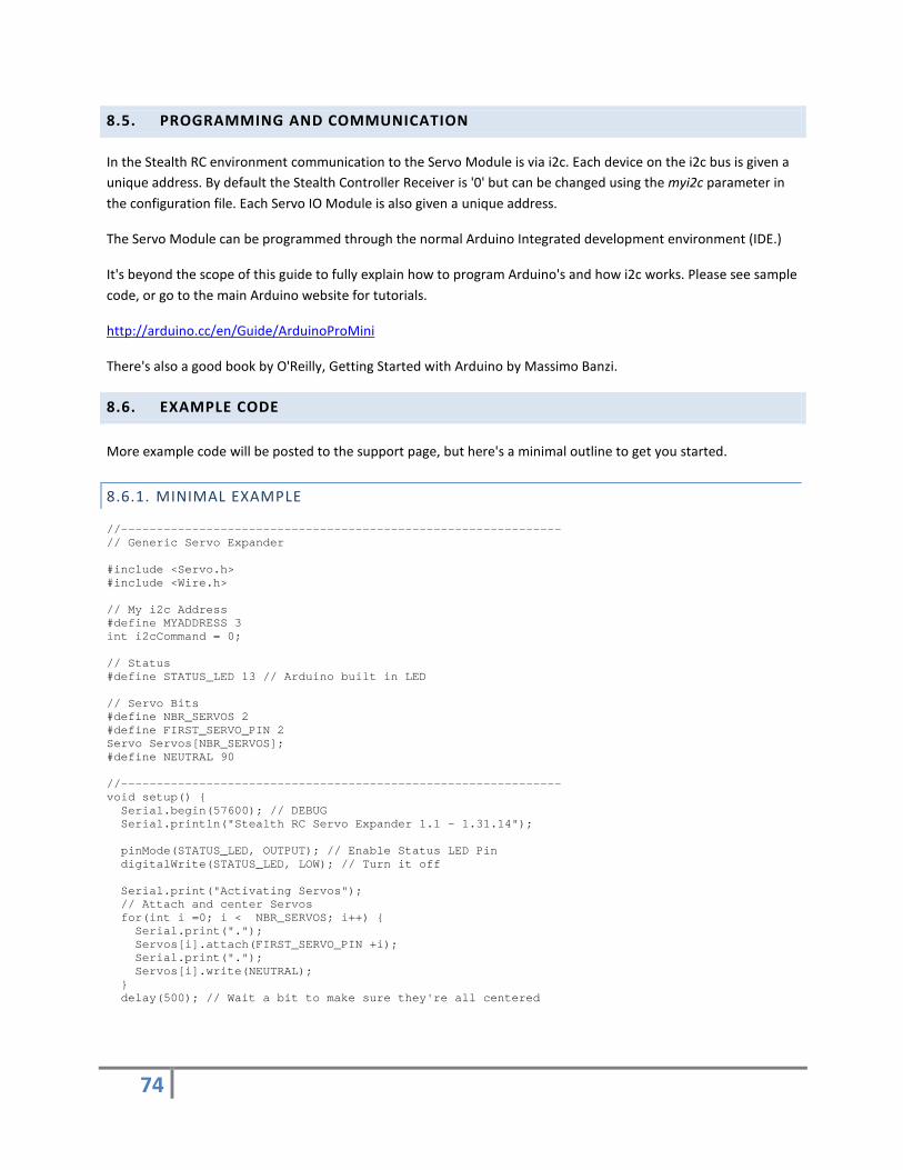
74
8.5. PROGRAMMING AND COMMUNICATION
In the Stealth RC environment communication to the Servo Module is via i2c. Each device on the i2c bus is given a unique address. By default the Stealth Controller Receiver is '0' but can be changed using the myi2c parameter in the configuration file. Each Servo IO Module is also given a unique address.
The Servo Module can be programmed through the normal Arduino Integrated development environment (IDE.)
It's beyond the scope of this guide to fully explain how to program Arduino's and how i2c works. Please see sample code, or go to the main Arduino website for tutorials.
http://arduino.cc/en/Guide/ArduinoProMini
There's also a good book by O'Reilly, Getting Started with Arduino by Massimo Banzi.
8.6. EXAMPLE CODE
More example code will be posted to the support page, but here's a minimal outline to get you started.
8.6.1. MINIMAL EXAMPLE //-------------------------------------------------------------- // Generic Servo Expander #include <Servo.h> #include <Wire.h> // My i2c Address #define MYADDRESS 3 int i2cCommand = 0; // Status #define STATUS_LED 13 // Arduino built in LED // Servo Bits #define NBR_SERVOS 2 #define FIRST_SERVO_PIN 2 Servo Servos[NBR_SERVOS]; #define NEUTRAL 90 //-------------------------------------------------------------- void setup() { Serial.begin(57600); // DEBUG Serial.println("Stealth RC Servo Expander 1.1 - 1.31.14"); pinMode(STATUS_LED, OUTPUT); // Enable Status LED Pin digitalWrite(STATUS_LED, LOW); // Turn it off Serial.print("Activating Servos"); // Attach and center Servos for(int i =0; i < NBR_SERVOS; i++) { Serial.print("."); Servos[i].attach(FIRST_SERVO_PIN +i); Serial.print("."); Servos[i].write(NEUTRAL); } delay(500); // Wait a bit to make sure they're all centered

75
// Detach from servo to safe power and stop jitter for(int i =0; i < NBR_SERVOS; i++) { Serial.print("."); Servos[i].detach(); } Serial.println(""); Serial.print("My i2c address:"); Serial.println(MYADDRESS); Wire.begin(MYADDRESS); // Start I2C Bus as a Slave Wire.onReceive(receiveEvent); // routine we call when we get a commandregister event i2cCommand = -1; // Make sure i2cCommand isn't set Serial.println("Listening for i2c Command"); } //-------------------------------------------------------------- // receive Event // this is called every time we detect an i2c command for us //-------------------------------------------------------------- void receiveEvent(int howMany) { i2cCommand = Wire.read(); // receive byte as an integer Serial.print("i2c Command = "); Serial.println(i2cCommand); } //-------------------------------------------------------------- // Perform this loop indefinitely //-------------------------------------------------------------- void loop() { if (i2cCommand == 0) { digitalWrite(STATUS_LED, LOW); i2cCommand=-1; } //-------------------------------------------------------------- // Status / Reset from Main Controller if (i2cCommand == 1) { // "1" is a special startup Stealth RC command. // It tells us the main Controller Receiver reset. // Typically we've just rebooted/reset too. // Status LED is set on to show we got the reset message Serial.println("Got reset message"); // Turn on Status LED so we can visually see that we got a reset command digitalWrite(STATUS_LED, HIGH); // Always reset i2cCommand to -1 or command will loop/repeat forever i2cCommand=-1; } //-------------------------------------------------------------- // Command 1 if (i2cCommand==2) { Serial.println("COMMAND 2!"); // Turn on Status LED to show we're in the command digitalWrite(STATUS_LED, HIGH); // Always reset i2cCommand to -1 or command will loop/repeat forever i2cCommand=-1; // Turn off Status LED digitalWrite(STATUS_LED, LOW); } }

76
9. PPM/PWM CONVERTER
9.1. OVERVIEW
The PPM/PWM Converter allows you to use a standard RC Receiver (RX) as a backup control device. A minimum of 4 channels are required for normal operation, but 6 or 8 are typical. 8 being the maximum.
As a bonus you can perform gestures and trigger sounds via your RC Transmitter.
The number radio channels should be configured in CONFIG.TXT using the rcchn parameter (rcchn=6, or rcchn=8). See 6.7.5. General Parameters.
(It may look like it's an Arduino Pro Mini, but it's running custom firmware to interpret the PWM signals and map them to a single PPM output stream.)
9.2. CONNECTING TO A RC RECEIVER
In summary, you connect the RC Receivers 6 or 8 channels using the short 3-pin jumper cables.
Then use a longer 3-pin jumper cable to connect the PPMOUT to PPMIN on the Stealth Controller.
Depending on your receiver, you may also need to connect RCRXPWR from the PPM Convert to your RC receivers Battery Power connection.
You can also reduce the cables needed by just connecting the data/signal pins instead of repeating the ground/voltage lines for each channel. But you will still need at least one ground/voltage connection.

77
9.3. MAPPING
CAUCTION: Not all RC Receivers outputs are labelled the same nor will they necessarily be in the same order on the RC Receiver.
Before we connect anything we need to first understand how the Stealth Remotes are mapped to the Stealth Controller Receivers servo channel outputs. They follow the standard RC convention, which may not seem logical, but that's the standard
.
Futaba typically labels their RC Receiver channels numerically, and JR/Spektrum uses the terms Aileron, Elevator, Rudder, Throttle, Gear and Auxiliary. To confuse matters, RC transmitters can come in "Mode 1" and "Mode 2". Most RC airplane remotes in the USA are Mode 2, and that's what this guide follows.
It's very important that all joysticks/channels (both conventional RC and Stealth RC) logically map the same way, otherwise your robot may respond differently depending on which remote you use. This includes any reverse setting you may have configure in the RC transmitter. This need to be duplicated in the servo parameters in CONFIG.TXT.
Stealth RC
PPM #
Futaba Mode 2
JK/Spektrum Mode 2
Label Function Label/Function Position
1 1 Aileron Aileron 2 2 2 Elevator Elevator 3 3 3 Throttle Throttle 1 4 4 Rudder Rudder 4 5 5 Gear Gear * 5 6 6 - Aux 1 6 7 7 - Aux 2 * 7 8 8 - Aux 3* 8
* label may vary on different receiver model

78
Because we're intercepting the RC signals we can remap them to perform Stealth RC operations.
Depending on the number of channels you have on your RC radio , you can assign channels 5-8 to either switches, knobs or dials - which can in turn map to volume, sound delay and to trigger sounds or start gestures.
9.3.1. 6 CHANNEL RADIOS
• Assign Channels 5 and 6 to on-off toggle switches. On the Stealth side we map these to Remote 1 - Buttons 5 and Remote 2 Button 10.This allows us to trigger random sounds and enter gestures.
• Unfortunately, we don't have enough channels for volume.
This configuration has been tested with a Futaba 6EX.
9.3.2. 8 CHANNEL RADIOS
Most 8 channel radios have a wide range of dials and switches, so we have some flexibility.
• Assign Channels 6 and 7 to a knob or dial. These will map to volume and random sound delay(Remote 2 - Thumb Wheels 3 and 4)
• Assign Channel 8 to an on-off-on toggle switch. Up maps to Gesture/Select (Remote 2 - Buttons 10), Down maps to Remote 1 - Button 5.
• Channel 5 is a pass thru channel, useful for controlling a direct attached servo.
This configuration has been tested on a Futaba 10G.
If you're 8 Channel RC radio does not have dials or an on-off-on toggle switch you may need to stick with just using 6 channels.

79
9.4. MIXING AND FAILSAFES
Most droids are driven in "tank mode" where channels 1 and 2 are mixed. This should be done in the Speed Controller and not in the RC radio.
Failsafes in RC Mode are handled in your RC Receiver.
9.5. PIN OUTS
Pins Description PWM 1-8 Connect to the RC Receiver outputs (G, V, Signal) RCRXPWR Connects to the RC Receiver Battery connection.
Do not accidentally power the RC Receiver from two different power sources at the same time. PPMOUT Connects to the Stealth Controller Receiver PPMIN. Passes PPM signal to Controller and also powers
the PPM Converter from the Controller.
See section Error! Reference source not found.. Error! Reference source not found. on how to recommendations how to configuration the radio.
9.6. STATUS LED
The PPM Converter has two LEDs, one is power and the second (green) is RC signal status.
Solid green means there is no valid RC signal detected (checked via channel 1). When no signal is detected the PPM Converter outputs neutral/centered values for all 8 channels.
Blink means we have a good signal (checked via channel 1) and all connected channels are being output via the PPM connection.
Remember failesafes are managed in the RC Transmitter/Receiver.

80
9.7. RC SELECT SWITCH
RC Mode is selected by enabling via the RCSEL header/jumper to use your conventional RC setup.
A simple two wire cable with a header plug on one end and a on/off toggle on the other is easily made up and mounted in a convenient location.

81
10. DC/DC CONVERTER
The Stealth RC setup requires a good +5V supply to operate. The DC Converter is a highly efficient voltage regulator. And designed to power all the devices in your Stealth RC setup, including the main Stealth Controller Receiver, Servo Expander Modules and a large number of servos.
You can either connect your +5V supply using regular wire to the PWR terminal block (up to 16 AWG)

82
or using a 2 or 3 pin jumper wire to the PWRHDR header behind the PWR terminal block

83
11. ADDITIONAL COMPONENTS
11.1. SPEED CONTROLLERS
Stealth RC has been tested with the following Speed Controllers:
• Dimension Engineering Syren 10 (Dome) • Dimension Engineering Sabertooth 2x25 (Drive, mixed/tank mode) • RoboteQ AX2500 (Drive, mixed/tank mode) • RoboteQ AX2250 (Drive, mixed/tank mode)
Dimension Engineering speed controllers need to be on a firmware release that supports DEScribe. This will allow you to fine tune power curves and set mixed/tank mode operation.
http://www.dimensionengineering.com/software/DEScribe/html/
Other speed controllers, for example from Vantec should work as they offer tank driving and adjustable power curves. But we've not tested them as of yet.
11.2. AMPLIFIERS
You will need an amplifier and speaker setup to use the MP3 Module. It's beyond the scope of this document to make recommendations beyond the caveat that some amplifiers may need a ground loop isolator to minimize interference and possible damage to the VMUSIC2 MP3 Module.

84
12. TROUBLESHOOTING/FAQ
12.1. STEALTH POCKET REMOTES
12.1.1. CAN I HOT-SWAP BETWEEN POCKET REMOTES AND RC MODE?
No, you have to power down. Flip your RC Select switch and then power back on.
12.1.2. I LOST THE SCREW / BUTTONS AFTER I OPENED UP THE CASE - WHERE CAN I GET MORE?
Please be careful not to lose the small buttons or screws when you open up the case. The remotes were not really designed to be opened in the field and the small parts are easily lost.
The small screw that holds the case together is a #0 18-8 1/4" Flat Head Sheet Metal Screw . McMaster-Carr part number 90065A020.
Spare buttons will be available to purchase soon.
12.1.3. WHAT BATTERY IS USED IN THE REMOTE?
The remotes use a small 3.7V 380-400mAh Li-Po batteries. See section 5.4.4 Replacing internal Batteries.
12.1.4. HOW LONG WILL BE REMOTES RUN FOR ON A FULL CHARGE?
Depending on the XBEE radios installed and condition/age of the battery you should get around 4 hours of use on 900MHz radios and 6 hours on 2.4GHz radios.
12.1.5. WHAT'S THE LIFE EXPECTANCY OF A BATTERY?
It really depends on how well you look after it and how often you use/charge it. Over time the charge the battery can hold will diminish and you'll get shorter and shorter run times between needing to recharge.
12.1.6. HOW LONG DOES IT TAKE TO CHARGE THE BATTERY?
From "empty", allow 2-3 hours to charge the battery fully - but time will vary depending on usage, age of battery and the amperage available from the USB power source.
12.1.7. THE BATTERY IS DEAD AND I CAN'T TELL IF THE REMOTE IS TURNED OFF OR ON
Looking at the back of the remote, the remote is turned on with the switch all the way to the left or off when it's to the right.
Or look for the little notch underneath that signifies the on position

85
12.1.8. THE YELLOW CHARGE LED IS BLINKING WHAT DOES IT MEAN?
When charging, the yellow status LED should be on constantly, and will turn off when done.
If it's blinking, it probably means the battery isn't hold a charge and the built in charger is cycling between detecting a full charge and needing to charge state.
You could try charging the battery on an external Li-Po charge but it's probably time to replace your battery.
12.1.9. CAN I USE THE REMOTES WHILE CHARGING?
You can use the remotes while charging, and it's handy to have an external booster battery to run your remotes when they're running low.
But there's a catch. First the remotes have to be charge to a certain level before they will turn on - this should only take a few minutes.
Second, once the battery is full, the built in charger turns its self off. It will not recheck the status of the battery until you unplug and reconnect the USB cable. So if you continue to use the remotes tethered to an external battery don't assume it will continue to charge the battery.
12.1.10. THE BATTERY IS SWOLLEN OR LEAKING - WHAT SHOULD I DO?
You should not attempt to charge the battery. Disconnect it immediately and dispose of correctly.
12.1.11. CAN I REPLACE THE XBEE RADIOS?
Yes, but you will need to reconfigure the radios and set the unique XBEE addresses in the CONFIG.TXT file. Documentation on how to do this will come later.
12.1.12. CAN I SWITCH MY XBEE RADIOS FROM 2.4GHZ TO 900MHZ OR VICE-VERSA?
Yes, but you will need to replace the radios. They're fixed at either 900MHz or 2.4GHz. As above you will need to reconfigure the replacement radios. Plus you may need to adjust some solder bridges in the remotes. Documentation on how to do this will come later.
12.1.13. THE J1 AND J2 LEDS KEEP ON FLASHING ON AND OFF
You may want to check your remote batteries. If power is too low to maintain a connection they will fail to sync with the receiver and eventually give up.

86
12.1.14. JOYSTICK VALUES DON'T REACH MIN/MAX (0-180)
I'm using the servo channel monitor screen and the values never reach the min/max (0-180) when I move the joysticks to their extreme positions. They seem to either stick at 1-4, or 178-179. The other extreme value on the same joystick works fine. What's going on?
First check your CONFIG.TXT servo line to max sure you've not capped the min/max allowed values, or if you've tweaked the trim value.
Another possible explanation. Analog joysticks are not perfect or identical, sometimes readings on the high, low and center can vary slightly from joystick to joystick. In everyday use you will probably not even notice the slight difference to be honest.
Some speed controller already have options take account of discrepancies in joystick; either by going thru a "calibrated" procedure or enabling "self-calibration" on the speed controller.
Starting with firmware release 1.0.9 you can also calibrate each joystick by setting values on the Stealth Controller Receiver. Using config.txt parameters rvr (Reference Voltage Right) and rvl (Reference Voltage Left). Default value is 1023, and typically it's set from 995 to 1023. In normal operation it wouldn't be changed once set/copied into the EEPROM.
Before shipping we verify/calibrate each joystick and will set a specific values for your setup. If you've upgraded from an earlier release please contact us for the best way to determine the optimal values.

87
12.2. STEALTH CONTROLLER RECEIVER
12.2.1. STARTUP HANGS WHEN I HAVE AN SERVO EXPANDER ATTACHED
Make sure you don't have conflicting i2c addresses set. Best to assign the Servo Expander(s) and address above 5 to be on the safe side.
12.2.2. WHEN WILL THE J.E.D.I. CONTROLLER BE SUPPORTED?
The J.E.D.I. controller is supported with release 1.0.8 of the firmware. Please see supplemental guide.
12.2.3. THE THUMBWHEELS ARE STIFF/HARD TO TURN
Over time they will loosen up and you can accelerate this by simply playing with them. It may be easier to do this with the top of the case removed.
If you have big thumbs, you can also try filing down the opening in the case - but the reason they're recessed so much is to avoid accidentally turning them.
12.2.4. DO YOU SUPPORT TEECES/JEDI LOGICS
Short answer yes, thru the use of the JAWALite and the Stealth Controllers Auxiliary Serial Command feature (added with the 1.0.8 release of the firmware.)

88
12.3. DRIVE SYSTEM
12.3.1. MY DROID IS VERY ERRATIC WHEN I TRY AND I CAN'T CONTROL HIM
The joysticks are very sensitive and they'll take getting used to, and you will need to fine tune the "ramp time" or speed/acceleration power curves configured on your speed controller.
Alternatively, the Stealth Controller offers rudimentary servo speed/acceleration capability that can be changed in the configuration file (see section 6.7.11 Servos and Channels.)
However, it's highly recommended that you try to first tune your speed controller as they have a wider range of options.
This isn't too hard to do, but beyond the scope of this document to outline the steps in detail.
The Stealth RC system has been tested on RoboteQ and Dimension Engineering (DE) speed controllers, both of which have a serial/PC interface to allow adjustment of these parameters.
Only DE controllers with DEScribe enabled firmware support parameter tuning. If you bought your DE controller prior to 2013 there's a good chance you will need to upgrade your firmware. DE will do this for free if you send it to them after asking for an RMA via their website (http://www.dimensionengineering.com)
For details on DEScribe:
http://www.dimensionengineering.com/software/DEScribe/html
Vantec speed controllers also offer different speed/power curves, which can be set using DIP switches. At this time this has not speed fully tested.
12.3.2. MY DROID WILL NOT GO FORWARD AND TURNS IN STRANGE DIRECTIONS
Please check your wires to make sure that you've not connect channel 1 and 2 to the wrong speed controller channel. You can also reverse direction of the motor or motors by flipping the wires that connect to the motor from the speed controller. Be very carefully not to confuse this with the input power to your speed controller.
Direction can also be change by reversing the direction of one or both of servo channels 1 and 2. See section 6.7.11 Servos and Channels.
If you're also using your convention RC remote, you should match the Stealth RC forward and reverse options with your RC remote.
At this time the controller does not support channel mixing or tank mode. This has to be set in your speed controller.
89
12.3.3. MY DOME SPINS THE WRONG WAY
Either reverse the polarity of the wires connecting to the motor or configure the servo channel to be reversed.
12.4. SERVO I/O EXPANDER
12.4.1. I HAVE A SERVO EXPANDER LOADED WITH THE EXAMPLE CODE BUT IT'S NOT RESPONDING TO I2C COMMANDS
Using the "basic" example code, on power up the Servo Expander should turn on its green status LED when the Stealth Controller Receiver initializes.
Things to check:
• Do you have power going to the servo bus? • Check it has a unique i2c address on your network. • Try disconnect all other i2c devices and try again. • Make sure you have at least one valid i2c gesture or button configuration command in CONFIG.TXT, and
the i2c addresses matches the one assigned in your Servo Expander code.
12.4.2. CAN THE SERVO EXPANDER RANDOMLY MOVE A DOME HP?
Short answer is yes. See support forum for example code (www.surerobotics.com/support)

90
12.4.3. CAN I CONNECT MY JEDI HP LED BOARDS DIRECTLY TO THE STEALTH SYSTEM?
Yes in principle you could connect them to one or more of the Digital Out connections. It's best to drive them from the Stealth Servo I/O Expander rather than the Stealth Controller Receiver as you'd save on running additional connections up to the dome.
Caution: The center pin on JEDI HP LED board connect to GND and should be disconnected/cut/disabled. The center pin on all the Stealth I/Os outputs are +5V. Connecting these without disabling the center wire will most likely cause a short and damage components in the system.
12.4.4. WHAT ABOUT JEDI DISPLAY, CAN I TRIGGER THEM FROM THE STEALTH RC SETUP?
Again, yes in principle. You could connect the J.E.D.I. Display Controller to a serial out connection on the Servo I/O Expander Module, and send J.E.D.I. command which could be triggered by an i2c command via a gesture or button.
Example code and wiring diagram is in the works.
12.4.5. CAN I CONTROL A TEECES LOGIC DISPLAY FROM THE STEALTH RC SETUP?
The best way to do this is to load the J.E.D.I. compatibility Teeces firmware and use a serial connection and J.E.D.I. commands as above.
12.5. SOUND SYSTEM
12.5.1. THERE'S STATIC COMING FROM MY SPEAKERS
Do you have ground loop isolator between the amplifier's and VMUSIC2? If not, install one.
12.5.2. THERE'S A CLICKING COMING FROM SPEAKERS
If you turn of the radios and/or remote the XBEE radio does the noise still happen?
Some amplifiers are sensitive to the 2.4GHz radios. You will either need to move the XBEE radio as far away from the amplifier as possible or replace the amplifier.
If the noise is still there with the radios disconnected/off - then try a test with ear buds/headphones in place of the amplifier. Is the noise there too? If not you may have a ground loop problem.

91
13. STEALTH CONTROLLER FIRMWARE
Stealth Controller Boards shipping since March 2015 came pre-loaded with the XBOOT Bootloader. This allows us to update the firmware via the serial/console connection instead of using an AVR Programmer. The main advantage is we no longer need the specialty programmer. Serial USB Adapters very common, and many people may have them in their toolkit to program the Arduinos (and Sure Robotics Servo Expanders). It can also be used to monitor/configure your controller via the command line interface.
One disadvantage is that on initial power the micro-controller waits a few seconds to check if you want to program new firmware.
You can still flash the firmware direct to the board and avoid XBOOT if you’d like. It’s really a personal choice.
Older boards pre-XBOOT loader can be upgraded. You will still need an AVR ISP Programmer to do it, but once done you can use the Serial Adapter going forward.
Flashing firmware can be tricky, and getting USB drivers to play nicely is often a problem. There’s always a chance you could “brick” the device if you miss a step but often can be recovered. If in doubt contact us and we’ll do the upgrade for you.
13.1. FIRMWARE REVISIONS AND DOWNLOADS
Release Date Description Download 0.15 10-24-2013 Limited BETA Release 1.0.0 01-31-2014 Expanded BETA Release 1.0.1 02-10-2014 Expanded BETA Release
Support config.txt lines longer than 80 chars surerobotics.com/firmware/SRC101.hex Checksum: 4090703212 Byte Count:129835
1.0.7 09-24-2014 Add support for 2.2 board. Extra status LEDs. Random or Sequential Sound Banks. Random Sound algorithm tweak to stop repeating same sound in quick succession.
surerobotics.com/firmware/SRC107.hex Checksum: 3814176247 Byte count: 147614
1.0.8 12-18-2014 Added initial JEDI Mode Support (release 4.0X) - Mimic JEDI RC Converter. String output on Aux Serial, e.g. can be used to drive JEDI/Teeces Logics and sync with sound or other microcontrollers. Allow action assignment to Button 9 (over-ride Enable/Disable function) Expanded Command Line Interface. Can now trigger all action types from the command line. Added Remote Command Line Interface via XBEE Serial Connection. Easier to reconfigure radios and tune for battery life, vs distance/joystick sensitivity.
surerobotics.com/firmware/SRC108.hex Checksum: 3199772734 Byte count: 181838
1.0.9 01-30-2015 Added rvl and rvr parameters to adjust surerobotics.com/firmware/SRC109.hex

92
2.4GHz radio reference voltage EEPROM Config now loads first on boot (always) and CONFIG.TXT overrides values Added joystick calibration routine.
Checksum: 2609558858 Byte count: 173849
1.0.10 04-12-2015 Enable Auto-Dome Incoming i2c command changes Add new commands
surerobotics.com/firmware/SRC_1_0_10.hex Checksum: 551767362 Byte Count: 190737
XBOOT 04-12-2015 surerobotics.com/firmware/SRC_xboot.hex Checksum: 3377361372 Byte Count: 8193
1.0.11 08-01-2015 Trim revisited Limit min/max pulse
surerobotics.com/firmware/SRC_1_0_11.hex Checksum: 1652509695 Byte Count: 192082
Currently all firmware will work on all 2.X boards, even though there are additional status LED on board >=2.2.
However, not all new functionality may work on older <=2.1 boards, e.g. the Wireless Remote Console, as the physical hardware is not there to support communication in both directions.

93
13.2. FIRMWARE UPGRADE PROCEDURE
13.2.1. SERIAL / USB FTDI XBOOT METHOD
You’re board needs to be using XBOOT bootloader for this method to work.
You will need avrdude installed/configured, or download the following zip file and put it in the same directory as your firmware.
www.surerobotics.com/firmware/avrdude.zip
STEP 1. Connect the Stealth Controller SER to a USB FTDI/Serial device.
STEP 2. Download firmware (hex file) and save it somewhere easy to find
STEP 3. Open Command Window (cmd.exe on Windows)
STEP 4. Change directory and flash firmware.
> cd FIRMWARE_LOCATION > avrdude -p atmega2560 -P com5 -c avr109 -b 115200 -U flash:w:SRC_1_0_11.hex
Change “com5” to whatever your USB com port number is. On Windows you can use “Device Manager” to figure it out.
If you’re using an older board (2.2 and below) you will need to hit the reset button as you run avrdude. This resets the chip and XBOOT should detect that you want to flash firmware.
94
13.2.2. UPGRADING TO XBOOT BOOTLOADER
Upgrading to XBOOT bootloader will allow you to flash future firmware using the easier Serial method. The procedure for flashing the XBOOT bootloader is very similar to programming the firmware direct to the ATMEL chip but instead of flashing the Stealth firmware you flash XBOOT.hex instead. Then use the above method to flash the firmware.
13.2.3. FLASHING FIRMWARE DIRECT
To program/flash new firmware direct to the AMTEL chip you will need an AVR In Circuit Serial Programmer (ICSP/ISP). We only support the official ATMEL AVR ISP ISP mkII and the newer AMTEL ICE AVR Programmer (ATATMEL-ICE-BASIC).
www.atmel.com/tools/atatmel-ice.aspx
There are cheaper options but we don't recommend or support them, and strongly suggest you use the official programmers from ATMEL.
If you opt to use XBOOT, you will only need to flash XBOOT once and hence only need the ISP programmer once. If you don’t own a programmer we’re happy to upgrade to XBOOT for you for free, you just need to cover return shipping.

95
13.2.3.1. CONNECTING PROGRAMMER
The programmer connects to the ICSP 6 pin header (next to Servo outputs on 2.1x boards and reset button on 2.2+ boards).
On the board there's a small white line next to pin #1. Most ISP cables have a bump/key on one side, the key should face the white line. Status LED on the AVRISP will turn green if you've plugged in the board correctly, or it will flash amber if it's the wrong way around. You can't damage the board if you plug it in the wrong way.
You will need to power the Stealth Controller board before you can program it.
2.1 Boards
2.2+ Boards

96
13.2.3.2. FIRMWARE UTILITY
You will need to download and install the Atmel Studio. Documented below is for version 6.2 but future versions should be very similar.
STEP 1. Start Device Programming from the Tools Menu

97
STEP 2. Select ATMEL-ICE or AVRISP mkII under Tool tab

98
STEP 3. It should automatically detect the ATmega2560 chip, if not find/select it.

99
STEP 4. Click APPLY, then READ. You should now have the following on your screen
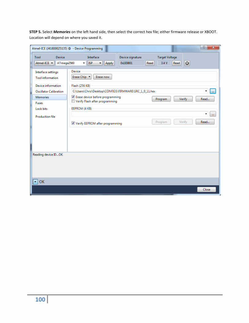
100
STEP 5. Select Memories on the left hand side, then select the correct hex file; either firmware release or XBOOT. Location will depend on where you saved it.

101
STEP 6. Click Program
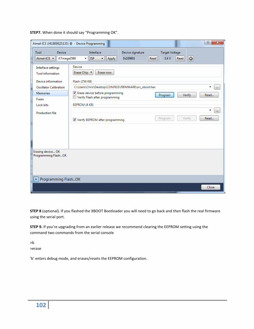
102
STEP7. When done it should say “Programming OK”.
STEP 8 (optional). If you flashed the XBOOT Bootloader you will need to go back and then flash the real firmware using the serial port.
STEP 9. If you’re upgrading from an earlier release we recommend clearing the EEPROM setting using the command two commands from the serial console
>b >erase
‘b’ enters debug mode, and erases/resets the EEPROM configuration.

103
14. FIRMWARE CHANGES
14.1. VERSION 1.0.10
Most significant is the enablement of the “Auto-Dome” feature.
Other changes that are worth noting as well:
• Play acknowledgment sound when random sounds enabled or disabled (see download link below). • Ability to set R/C min/max pulse on a per channel basis. • How incoming i2c commands are handled on the main controller has been changed. It can now receive
full text/command line “commands” via i2c instead of just playing sounds. A new Servo I/O Expander/Arduino Library and examples will be included to show how to interface with it and update existing code.
If you’re coming from a very old release (<1.0.8) then you may want to review the current reference guide as there’s a lot of changes that happened in 1.0.9. For example how we calibrate joysticks.
Additional sounds: http://www.surerobotics.com/doc/additional-mp3.zip
14.2. VERSION 1.0.11
• Trim revisited. We now always apply trim, even when stick is centered. • Limit min/max pulse, min pulse can't be greater than 1000 and max pulse can't be less than 2000. • Display EEPROM content fix (was showing live config) • dome_mode value on startup was wrong, needed to subtract 1.


