Section 15 Auxiliary Steam Boilers A. General 1. Scope 1.1 For the purpose of these requirements, the term "boiler" includes all closed vessels and piping systems used for: – generating steam at a pressure above atmos- pheric pressure (steam generators) – raising the temperature of water above the boil- ing point corresponding to atmospheric pressure (hot water generators) The term "steam generator" also includes any equip- ment directly connected to the aforementioned vessels or piping systems in which the steam is superheated or cooled, external drums, the circulating lines and the casings of circulating pumps serving forced-circula- tion boilers. 1.2 For hot water generators with a permissible discharge temperature of not more than 120 °C and all systems incorporating steam or hot water generators which are heated solely by steam or hot liquids Section 16 applies regarding materials, design calcula- tions and manufacturing principles. For equipment and testing G. applies. 2. Other requirements As regards their construction, equipment and opera- tion, steam boiler plants are also required to comply with the applicable national regulations. 3. Documents for approval Drawings of all boiler parts subject to pressure, such as drums, headers, tubes, manholes and inspection covers etc., are to be submitted to GL in triplicate. These drawings must contain all the data necessary for strength calculations and design assessment, such as working pressures, superheated steam temperatures, materials to be used and full details of welds including filler materials. Details and drawings are also to be submitted covering the valves and fittings and their arrangement together with a description of the boiler plant specifying the arrangement of the boiler with reference to the ship's longitudinal axis, the essential boiler data and equip- ment items, e.g. steam conditions, heating surfaces, allowable steam output, feed, firing system, safety valves, controllers and limiters. 4. Definitions 4.1 Steam boiler walls Steam boiler walls are the walls of the steam and wa- ter spaces located between the boiler isolating devices. The bodies of these isolating devices are part of the boiler walls. 4.2 Maximum allowable working pressure The maximum allowable working pressure PB is the approved steam pressure in bar (gauge pressure) in the saturated steam space prior to entry into the superhea- ter. In once-through forced flow boilers, the maximum allowable working pressure is the pressure at the su- perheater outlet or, in the case of continuous flow boilers without a superheater, the steam pressure at the steam generator outlet. 4.3 Heating surface The heating surface is that part of the boiler walls through which heat is supplied to the system, i.e.: – the area [m 2 ] measured on the side exposed to fire or exhaust gas – in the case of electrical heating, the equivalent heating surface H = 000 18 860 P ⋅ [m 2 ] P = electric power [kW] 4.4 Allowable steam output The allowable steam output is the maximum quantity of steam which can be produced continuously by the steam generator operating under the design steam conditions. 5. Lowest water level - highest flue - dropping time 5.1 The highest flue is the highest point of the heating surface on the side which is in contact with the water and is exposed to the flame radiation, or which is heated by gases of which temperature exceeds III - Part 1 GL 2004 Section 15 Auxiliary Steam Boilers Chapter 4 Page 15–1 A
Transcript
Section 15
Auxiliary Steam Boilers
A. General
1. Scope
1.1 For the purpose of these requirements, the term "boiler" includes all closed vessels and piping systems used for:
– generating steam at a pressure above atmos-pheric pressure (steam generators)
– raising the temperature of water above the boil-ing point corresponding to atmospheric pressure (hot water generators)
The term "steam generator" also includes any equip-ment directly connected to the aforementioned vessels or piping systems in which the steam is superheated or cooled, external drums, the circulating lines and the casings of circulating pumps serving forced-circula-tion boilers.
1.2 For hot water generators with a permissible discharge temperature of not more than 120 °C and all systems incorporating steam or hot water generators which are heated solely by steam or hot liquids Section 16 applies regarding materials, design calcula-tions and manufacturing principles. For equipment and testing G. applies.
2. Other requirements
As regards their construction, equipment and opera-tion, steam boiler plants are also required to comply with the applicable national regulations.
3. Documents for approval
Drawings of all boiler parts subject to pressure, such as drums, headers, tubes, manholes and inspection covers etc., are to be submitted to GL in triplicate. These drawings must contain all the data necessary for strength calculations and design assessment, such as working pressures, superheated steam temperatures, materials to be used and full details of welds including filler materials.
Details and drawings are also to be submitted covering the valves and fittings and their arrangement together with a description of the boiler plant specifying the arrangement of the boiler with reference to the ship's longitudinal axis, the essential boiler data and equip-ment items, e.g. steam conditions, heating surfaces,
Steam boiler walls are the walls of the steam and wa-ter spaces located between the boiler isolating devices. The bodies of these isolating devices are part of the boiler walls.
4.2 Maximum allowable working pressure
The maximum allowable working pressure PB is the approved steam pressure in bar (gauge pressure) in the saturated steam space prior to entry into the superhea-ter. In once-through forced flow boilers, the maximum allowable working pressure is the pressure at the su-perheater outlet or, in the case of continuous flow boilers without a superheater, the steam pressure at the steam generator outlet.
4.3 Heating surface
The heating surface is that part of the boiler walls through which heat is supplied to the system, i.e.:
– the area [m2] measured on the side exposed to fire or exhaust gas
– in the case of electrical heating, the equivalent heating surface
H = 00018
860P ⋅ [m2]
P = electric power [kW]
4.4 Allowable steam output
The allowable steam output is the maximum quantity of steam which can be produced continuously by the steam generator operating under the design steam conditions.
5. Lowest water level - highest flue - dropping time
5.1 The highest flue is the highest point of the heating surface on the side which is in contact with the water and is exposed to the flame radiation, or which is heated by gases of which temperature exceeds
400 °C at maximum continuous power. The highest flue on water tube boilers with an upper steam drum is the top edge of the highest gravity tubes.
5.2 The requirements relating to the highest flue do not apply to
– water tube boiler risers up to an outer diameter of 102 mm
– once-through forced flow boilers
– superheaters
– flues and exhaust gas heated parts in which the temperature of the heating gases does not ex-ceed 400 °C at maximum continuous power
5.3 The lowest water level must lie at least 150 mm above the highest flue even if the ship heels 4° to either side. Heated surfaces with a specified highest flue must remain wetted even at the static heeling angles of the ship laid down in Section 1, D., Table 1.1. The set point of the low water level limiter is crucial for the height of the water level.
5.4 The heat accumulated in furnaces and other heated boiler parts may not lead to any undue lower-ing of the water level due to subsequent evaporation when the firing system is switched off.
The lowest water level is to be set so that the dropping time is not less than 5 minutes.
5.5 The "dropping time" is the time to drop the water level from the lowest water level to the level of the highest flue under the condition of interrupted feed and allowable steam output.
T = 'v D
V60
⋅⋅
[min]
T = dropping time
V = volume of water in steam boiler between the lowest water level and the highest flue [m3]
D = allowable steam output [kg/h]
v' = specific volume of water at saturation tem-perature [m3/kg]
5.6 The lowest specified water level is to be indicated permanently on the boiler shell by means of a water level pointer. Reference plates are to be at-tached additionally beside or behind the water level gauges pointing at the lowest water level.
6. Manual operation
6.1 A facility is to be provided for manual opera-tion. At least the water level limiters must remain active even in manual operation.
6.2 Manual operation demands permanent and direct supervision of the system.
6.3 For detailed requirements in respect of man-ual operation of the firing system see Section 17.
B. Materials
1. General requirements
Materials for steam boilers have to satisfy special technical requirements, i.e. during manufacturing their workability and good weldability will be needed, for the subsequent operation of the boiler particularly high-temperature strength has to be ensured.
2. Approved materials
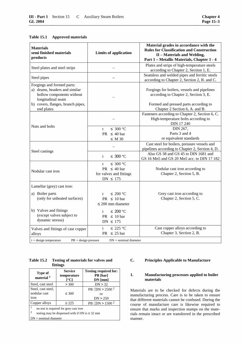
If the materials defined in Table 15.1 are used, the requirements specified in 1. are recognized as having been complied with.
For materials which are not defined in this Table manufacturers have to proof suitability for steam boil-ers and adequate mechanical properties of the chosen material to GL.
3. Material testing
3.1 The materials of boiler parts subject to pres-sure, including flue gas economizer tubes, must be tested by GL in accordance with the GL Rules II –Materials and Welding, cf. Table 15.1.
Material testing by GL may be waived in the case of:
– small boiler parts made of unalloyed steels, such as stay bolts, stays of ≤ 100 mm diameter, rein-forcing plates, handhole and manhole closures, forged flanges up to a nominal diameter DN 150 and branch pipes up to DN 150
– smoke tubes (tubes subject to external pressure)
The properties of these materials are to be attested by material certificates in accordance with EN 10 204 3.1. B.
3.2 Special agreements may be made regarding the testing of unalloyed steels to recognized standards.
3.3 The materials of valves and fittings must be tested by GL in accordance with the data specified in Table 15.2 for allowable working pressure PB and nominal diameters DN.
3.4 Parts not subject to material testing, such as external supports, lifting brackets, pedestals, etc. must be designed for the intended purpose and must be made of suitable materials.
Chapter 4 Page 15–2
Section 15 Auxiliary Steam Boilers III - Part 1GL 2004
B
Table 15.1 Approved materials
Materials semi finished materials products
Limits of application
Material grades in accordance with the Rules for Classification and Construction
II – Materials and Welding, Part 1 – Metallic Materials, Chapter 1 - 4
Steel plates and steel strips – Plates and strips of high-temperature steels
according to Chapter 2, Section 1, E.
Steel pipes – Seamless and welded pipes and ferritic steels according to Chapter 2, Section 2, B. and C.
Forgings and formed parts: a) drums, headers and similar
hollow components without longitudinal seam
b) covers, flanges, branch pipes, end plates
–
Forgings for boilers, vessels and pipelines
according to Chapter 2, Section 3, E.
Formed and pressed parts according to Chapter 2 Section 6, A. and B.
– Fasteners according to Chapter 2, Section 6, C.
High-temperature bolts according to DIN 17 240
Nuts and bolts t ≤ 300 °C PR ≤ 40 bar ≤ M 30
DIN 267, Parts 3 and 4
or equivalent standards
– Cast steel for boilers, pressure vessels and
pipelines according to Chapter 2, Section 4, D. Steel castings
t ≤ 300 °C Also GS 38 and GS 45 to DIN 1681 and
GS 16 Mn5 and GS 20 Mn5 acc. to DIN 17 182
Nodular cast iron
t ≤ 300 °C PR ≤ 40 bar
for valves and fittings DN ≤ 175
Nodular cast iron according to Chapter 2, Section 5, B.
Lamellar (grey) cast iron:
a) Boiler parts (only for unheated surfaces)
b) Valves and fittings
(except valves subject to dynamic stresss)
t ≤ 200 °C PR ≤ 10 bar
≤ 200 mm diameter
t ≤ 200 °C PR ≤ 10 bar DN ≤ 175
Grey cast iron according to Chapter 2, Section 5, C.
Valves and fittings of cast copper alloys
t ≤ 225 °C PR ≤ 25 bar
Cast copper alloys according to Chapter 3, Section 2, B.
t = design temperature PR = design pressure DN = nominal diameter
Table 15.2 Testing of materials for valves and fittings
DN > 250 Copper alloys ≤ 225 PB ⋅ DN > 1500 2 1 no test is required for grey cast iron 2 testing may be dispensed with if DN is ≤ 32 mm
DN = nominal diameter
C. Principles Applicable to Manufacture
1. Manufacturing processes applied to boiler materials
Materials are to be checked for defects during the manufacturing process. Care is to be taken to ensure that different materials cannot be confused. During the course of manufacture care is likewise required to ensure that marks and inspection stamps on the mate-rials remain intact or are transferred in the prescribed manner.
Boiler parts whose structure has been adversely af-fected by hot or cold forming are to be subjected to heat treatment in accordance with GL Rules II – Mate-rials and Welding, Part 1 – Metallic Materials, Chap-ter 2 – Steel and Iron Materials, Section 6, A.
2. Welding
Boilers are to be manufactured by welding. The exe-cution of welds, the approval of welding shops and the qualification testing of welders are to be in accordance with GL Rules II – Materials and Welding, Part 3 – Welding, Chapter 3 – Welding in the Various Fields of Application, Section 2.
3. Tube expansion
Tube holes must be carefully drilled and deburred. Sharp edges are to be chamfered. Tube holes should be as close as possible to the radial direction, particu-larly in the case of small wall thicknesses.
Tube ends to be expanded are to be cleaned and checked for size and possible defects. Where neces-sary, tube ends are to be annealed before being ex-panded.
Smoke tubes with welded connection between tube and tube plate at the entry of the second path shall be roller expanded before and after welding.
4. Stays, stay tubes and stay bolts
4.1 Stays, stay tubes and stay bolts are to be so arranged that they are not subjected to undue bending or shear forces.
Stress concentrations at changes in cross-section, in threads and at welds are to be minimized by suitable component geometry.
4.2 Stays and stay bolts are to be welded prefera-bly by full penetration. Possible stresses due to vibra-tion of long stays have to be considered.
4.3 Stays are to be drilled at both ends in such a way that the holes extend at least 25 mm into the wa-ter or steam space. Where the ends have been upset, the continuous shank must be drilled to a distance of at least 25 mm.
4.4 Wherever possible, the angle formed by gus-set stays and the longitudinal axis of the boiler shall not exceed 30 °. Stress concentrations at the welds of gusset stays are to be minimized by suitable compo-nent geometry. Welds are to be executed as full pene-tration welds. In firetube boilers, gusset stays are to be located at least 200 mm from the firetube.
4.5 Where flat surfaces exposed to flames are stiffened by stay bolts, the distance between centres of these bolts shall not exceed 200 mm.
5. Stiffeners, straps and lifting eyes
5.1 Where flat end surfaces are stiffened by pro-file sections or ribs, the latter shall transmit their load directly, i.e. without welded-on straps, to the boiler shell.
5.2 Doubling plates may not be fitted at parts under pressure subject to flame radiation.
Where necessary to protect the walls of the boiler, strengthening plates are to be fitted below supports and lifting brackets.
6. Welding of flat unrimmed ends to boiler shells
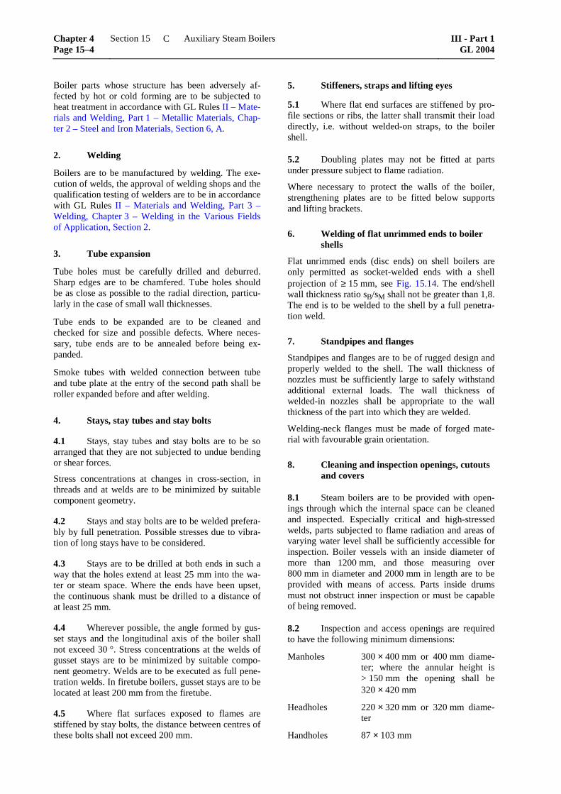
Flat unrimmed ends (disc ends) on shell boilers are only permitted as socket-welded ends with a shell projection of ≥ 15 mm, see Fig. 15.14. The end/shell wall thickness ratio sB/sM shall not be greater than 1,8. The end is to be welded to the shell by a full penetra-tion weld.
7. Standpipes and flanges
Standpipes and flanges are to be of rugged design and properly welded to the shell. The wall thickness of nozzles must be sufficiently large to safely withstand additional external loads. The wall thickness of welded-in nozzles shall be appropriate to the wall thickness of the part into which they are welded.
Welding-neck flanges must be made of forged mate-rial with favourable grain orientation.
8. Cleaning and inspection openings, cutouts and covers
8.1 Steam boilers are to be provided with open-ings through which the internal space can be cleaned and inspected. Especially critical and high-stressed welds, parts subjected to flame radiation and areas of varying water level shall be sufficiently accessible for inspection. Boiler vessels with an inside diameter of more than 1200 mm, and those measuring over 800 mm in diameter and 2000 mm in length are to be provided with means of access. Parts inside drums must not obstruct inner inspection or must be capable of being removed.
8.2 Inspection and access openings are required to have the following minimum dimensions:
Manholes 300 × 400 mm or 400 mm diame-ter; where the annular height is > 150 mm the opening shall be 320 × 420 mm
Headholes 220 × 320 mm or 320 mm diame-ter
Handholes 87 × 103 mm
Chapter 4 Page 15–4
Section 15 Auxiliary Steam Boilers III - Part 1GL 2004
C
Sightholes diameter of at least 50 mm; they should, however, be provided only where the design of the equipment makes a handhole impracticable.
8.3 The edges of manholes and other openings, e. g. for domes, are to be effectively reinforced if the plate has been inadmissible weakened by the cutouts. The edges of openings closed with covers are to be reinforced by flanging or by welding on edge stiffen-ers if it is likely that the tightening of the crossbars etc. would otherwise cause undue distortion of the edge of the opening.
8.4 Cover plates, manhole frames and crossbars must be made of ductile material (not grey or malle-able cast iron). Grey cast iron (at least GG-20) may be used for handhole cover crossbars of headers and sectional headers, provided that the crossbars are not located in the heating gas flow. Unless metal packings are used, cover plates must be provided on the exter-nal side with a rim or spigot to prevent the packing from being forced out. The gap between this rim or spigot and the edge of the opening is to be uniform around the periphery and may not exceed 2 mm for boilers with a working pressure of less than 32 bar, or 1 mm where the pressure is 32 bar or over. The height of the rim or spigot must be at least 5 mm greater than the thickness of the packing.
8.5 Only continuous rings may be used as pack-ing. The materials used must be suitable for the given operating conditions.
9. Boiler drums, shell sections, headers and firetubes
For welding of boiler drums, shell sections, headers and fire tubes see the GL Rules II – Materials and Welding, Part 3 – Welding, Chapter 3 – Welding in the Various Fields of Application, Section 2.
D. Design Calculation
1. Design principles
1.1 Range of applicability of design formulae
1.1.1 The following strength calculations represent the minimum requirements for normal operating con-ditions with mainly static loading. Separate allowance must be made for additional forces and moments of significant magnitude.
1.1.2 The wall thicknesses arrived at by applying the formulae are the minima required. The undersize tolerances permitted in GL Rules II – Materials and Welding are to be added to the calculated values.
The greater undersize tolerances for tubes which are only localized, need not to be considered.
1.2 Design pressure PR [bar] Formula symbol: pc
1.2.1 The design pressure is to be at least the maximum allowable working pressure. Additional allowance is to be made for static pressures of more than 0,5 bar.
1.2.2 In designing once-through forced flow boil-ers, the pressure to be applied is the maximum work-ing pressure anticipated in main boiler sections at maximum allowable continuous load.
1.2.3 The design pressure applicable to the super-heated steam lines from the boiler is the maximum working pressure which safety valves prevent from being exceeded.
1.2.4 In the case of boiler parts which are subject in operation to both internal and external pressure, e. g. attemporators in boiler drums, the design may be based on the differential pressure, provided that it is certain that in service both pressures will invariably occur simultaneously. However, the design pressure of these parts is to be at least 17 bar. The design is also required to take account of the loads imposed during the hydrostatic pressure test.
1.3 Design temperature t
Strength calculations are based on the temperature at the centre of the wall thickness of the component in question. The design temperature is made up of the reference temperature and a temperature addition in accordance with Table 15.3. The minimum value is to be taken as 250 °C.
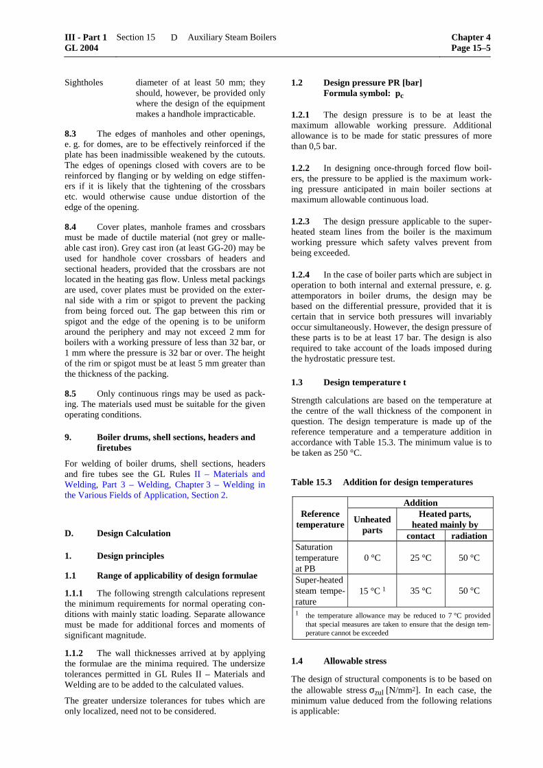
Table 15.3 Addition for design temperatures
Addition Heated parts,
heated mainly by Reference
temperature Unheated parts
contact radiation Saturation temperature at PB
0 °C
25 °C
50 °C
Super-heated steam tempe-rature
15 °C 1
35 °C
50 °C
1 the temperature allowance may be reduced to 7 °C provided that special measures are taken to ensure that the design tem-perature cannot be exceeded
1.4 Allowable stress
The design of structural components is to be based on the allowable stress σzul [N/mm2]. In each case, the minimum value deduced from the following relations is applicable:
°20,mR = guaranteed minimum tensile strength at room temperature [N/mm²]
t,eHR = guaranteed minimum yield stress at design temperature t [N/mm2]
Design temperature > 350 °C:
m,100000,tR
1,5
m,100000,tR
= average breaking strength after 100000 h of operation at design tem-perature t [N/mm2]
1.4.2 Cast materials
a) Cast steel: m,20 eH,t m,100000,tR R R, ,
3, 2 2,0 2,0°
b) Nodular cast iron: m,20 eH,tR R,
4,8 3,0°
c) Grey cast iron: Rm,20
11°
1.4.3 Special arrangements may be agreed for high-ductility austenitic steels.
1.4.4 In the case of cylinder shells with cutouts and in contact with water, a nominal stress of 170 N/mm2 shall not be exceeded in view of the protective mag-netite layer.
1.4.5 Mechanical characteristics are to be taken from the GL Rules II – Materials and Welding or from the standards specified therein.
1.5 Allowance for corrosion and wear
The allowance for corrosion and wear is to be c = 1 mm. For plate thicknesses of 30 mm and over and for stainless materials, this allowance may be dispensed with.
1.6 Special cases
Where boiler parts cannot be designed in accordance with the following rules or on general engineering principles, the dimensions in each individual case must be determined by tests, e.g. by strain measure-ments.
2. Cylindrical shells under internal pressure
2.1 Scope
The following design requirements apply to drums, shell rings and headers up to a diameter ratio Da/Di of up to 1,7. Diameter ratios of up to Da/Di = 2 may be permitted provided that the wall thickness is ≤ 80 mm.
2.2 Symbols
pc = design pressure [bar]
s = wall thickness [mm]
Di = inside diameter [mm]
Da = outside diameter [mm]
c = allowance for corrosion and wear [mm]
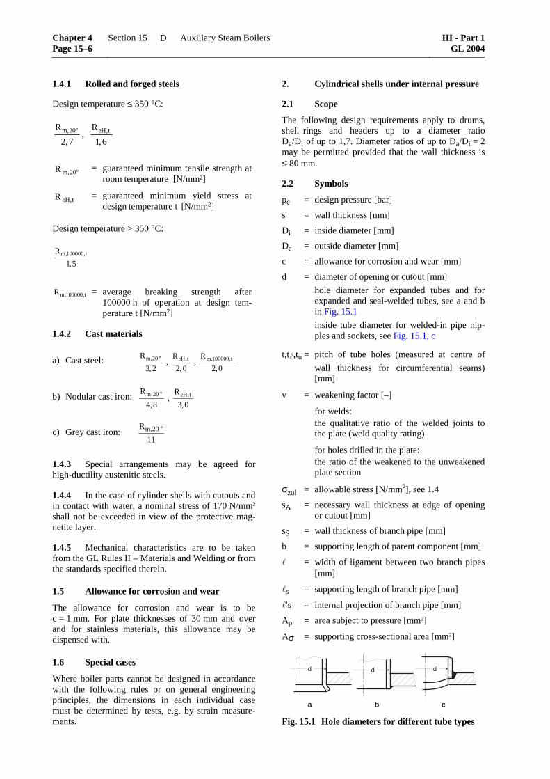
d = diameter of opening or cutout [mm]
hole diameter for expanded tubes and for expanded and seal-welded tubes, see a and b in Fig. 15.1
inside tube diameter for welded-in pipe nip-ples and sockets, see Fig. 15.1, c
t,t ,tu = pitch of tube holes (measured at centre of
wall thickness for circumferential seams) [mm]
v = weakening factor [–]
for welds: the qualitative ratio of the welded joints to
the plate (weld quality rating)
for holes drilled in the plate: the ratio of the weakened to the unweakened
plate section
σzul = allowable stress [N/mm2], see 1.4
sA = necessary wall thickness at edge of opening or cutout [mm]
sS = wall thickness of branch pipe [mm]
b = supporting length of parent component [mm]
= width of ligament between two branch pipes [mm]
s = supporting length of branch pipe [mm]
's = internal projection of branch pipe [mm]
Ap = area subject to pressure [mm2]
Aσ = supporting cross-sectional area [mm2]
d
a b c
d d
Fig. 15.1 Hole diameters for different tube types
Chapter 4 Page 15–6
Section 15 Auxiliary Steam Boilers III - Part 1GL 2004
D
2.3 Calculation of parameters
2.3.1 The necessary wall thickness s is given by the expression:
sD p
v pca c
zul c= ⋅
⋅ ⋅ ++
20 σ (1)
2.3.2 In the case of heated drums and headers with a maximum allowable working pressure of more than 25 bar, special attention is to be given to thermal stresses. For heated drums not located in the first pass (gas temperature up to 1000 °C max.), special certifi-cation in respect of thermal stresses may be waived subject to the following provisions: Wall thickness up to 30 mm and adequate cooling of the walls by virtue of close tube arrangement.
The description "close tube arrangement" is applicable if the ligament perpendicular to the direction of gas flow and parallel to the direction of gas flow does not exceed 50 mm and 100 mm respectively.
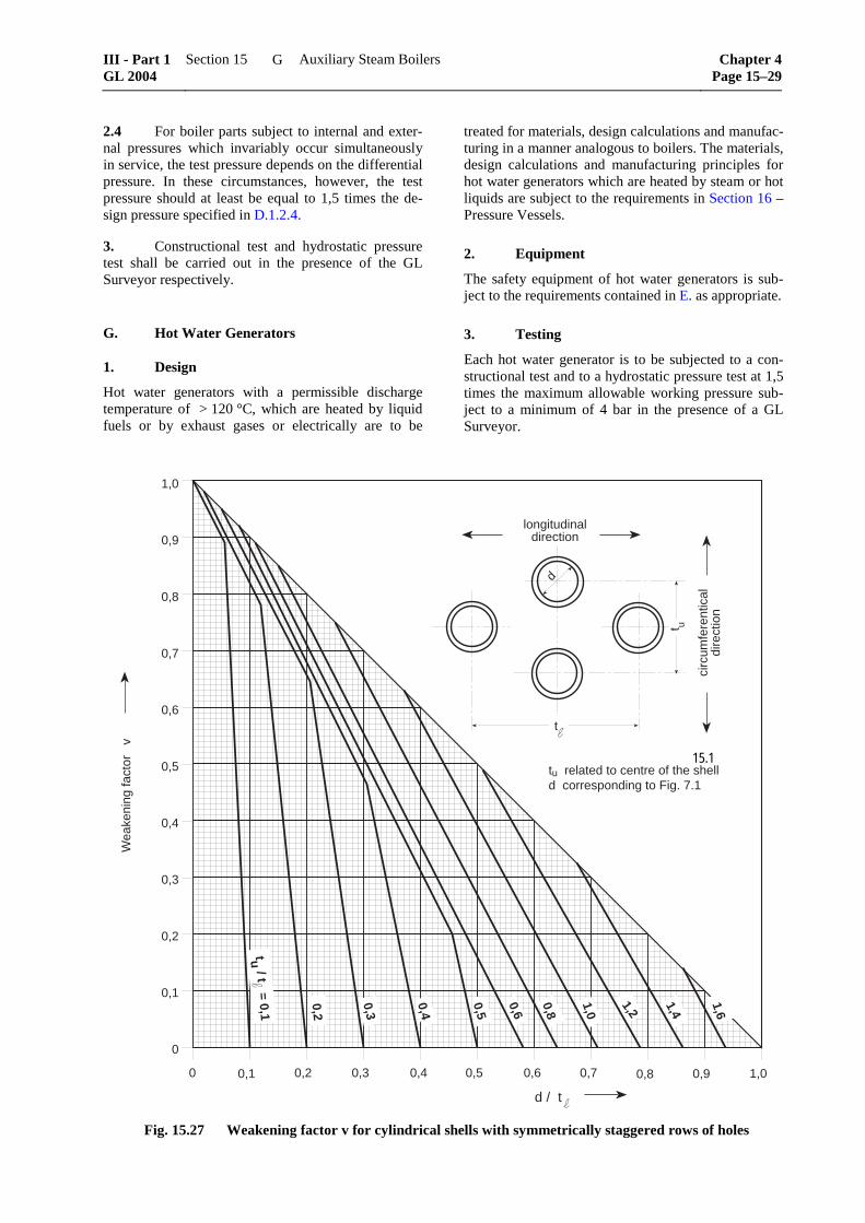
2.3.3 Weakening factor v
The weakening factor v is defined in Table 15.4 and in Fig. 15.27.
Table 15.4 Weakening factor v
Construction Weakening factor v
Seamless shell rings and drums
1,0
Shell rings and drums with longitudinal weld
weld quality rating see Rules for Welding
Rows of holes 1 in:
longitudinal direction
circumferential direction
t d
t
−
2 ⋅ −t d
tu
u
1 The value of v for rows of holes may not be made greater than 1.0 in the calculation. For staggered pitches, see Fig. 15.27
Refer also to Figures 15.1 a - c in 2.2.
2.3.4 Weakening effects due to cutouts or individ-ual branch pipes are to be taken into account by com-pensation of areas in accordance with the expression:
zulpc
2
1
A
A
10
pσ≤
+⋅
σ (2)
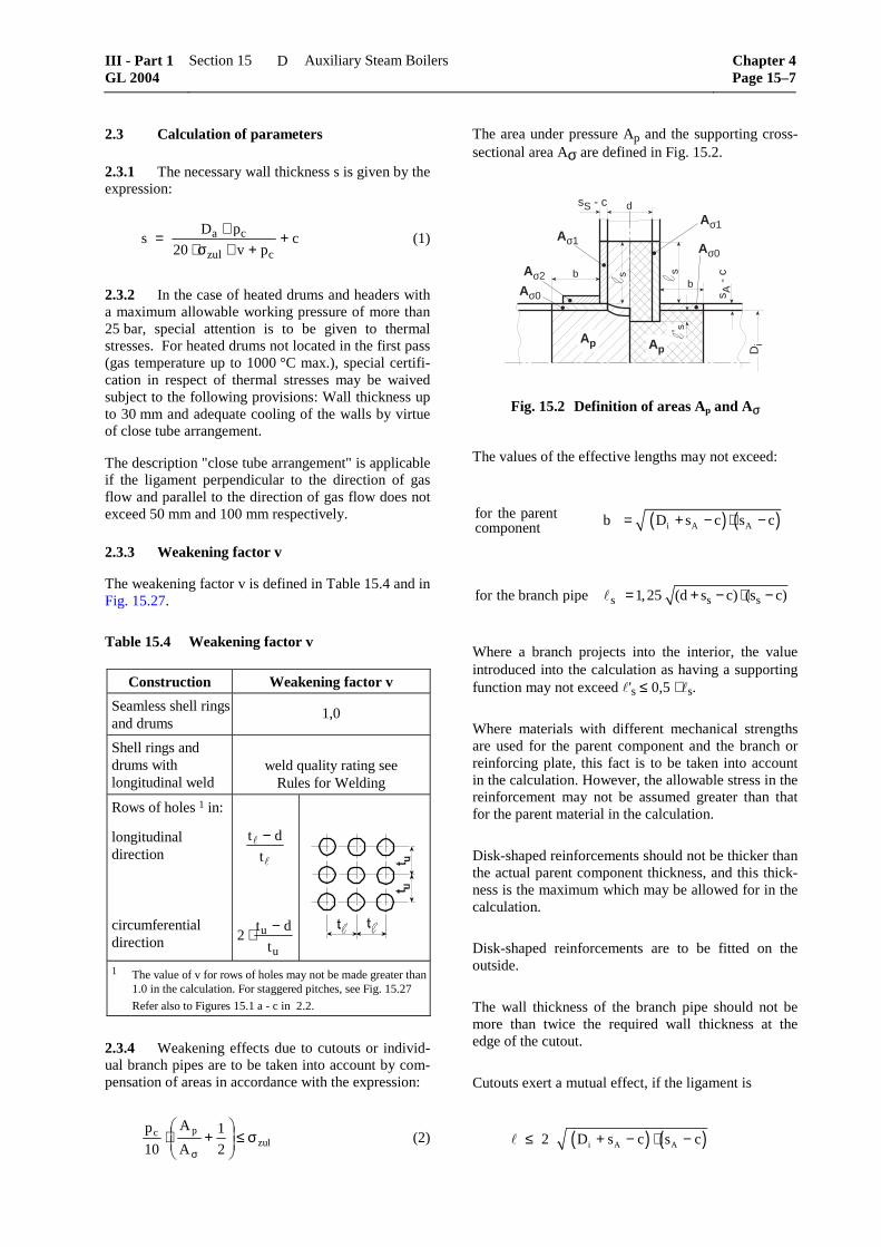
The area under pressure Ap and the supporting cross-sectional area Aσ are defined in Fig. 15.2.
Aσ1
Ap
Aσ2
Aσ0
Di
s A -
c
Ap
b
' s
b
dsS - c
l ss
Aσ1
Aσ0
s
Fig. 15.2 Definition of areas Ap and Aσ
The values of the effective lengths may not exceed:
( ) ( )i A Afor the parent b D s c s ccomponent = + − ⋅ −
s s sfor the branch pipe 1,25 (d s c) (s c)= + − ⋅ −
Where a branch projects into the interior, the value introduced into the calculation as having a supporting function may not exceed 's ≤ 0,5 ⋅ s.
Where materials with different mechanical strengths are used for the parent component and the branch or reinforcing plate, this fact is to be taken into account in the calculation. However, the allowable stress in the reinforcement may not be assumed greater than that for the parent material in the calculation.
Disk-shaped reinforcements should not be thicker than the actual parent component thickness, and this thick-ness is the maximum which may be allowed for in the calculation.
Disk-shaped reinforcements are to be fitted on the outside.
The wall thickness of the branch pipe should not be more than twice the required wall thickness at the edge of the cutout.
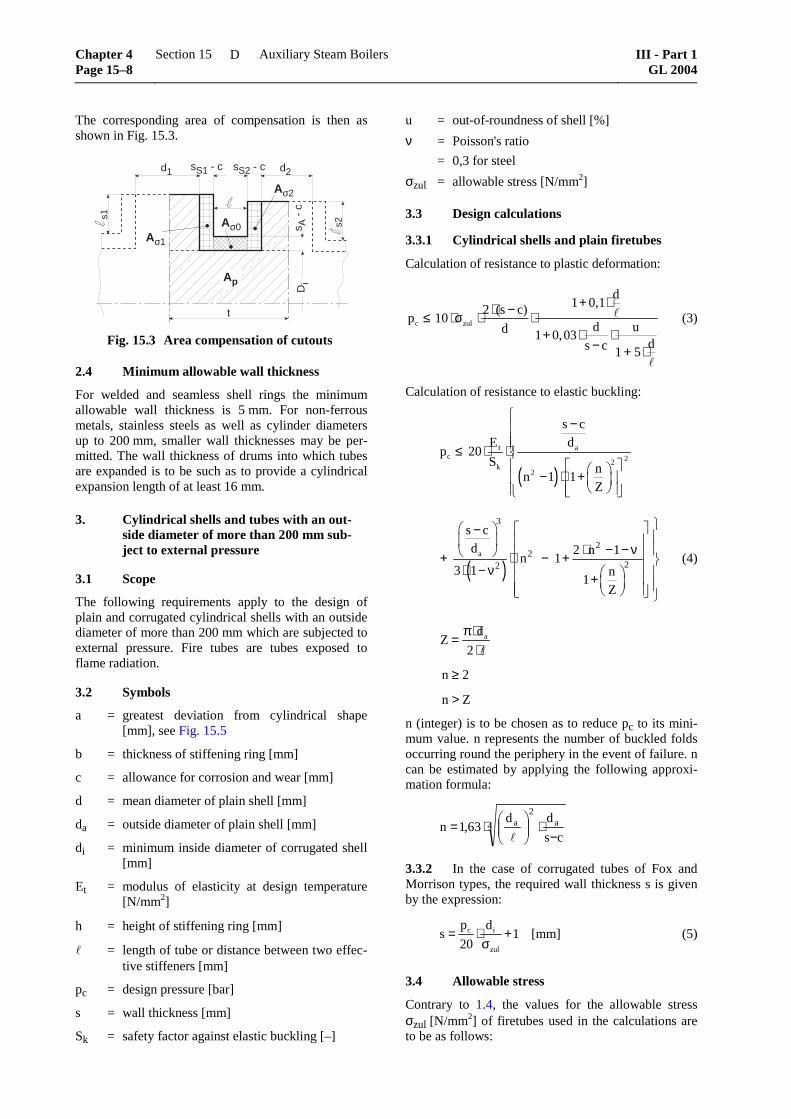
The corresponding area of compensation is then as shown in Fig. 15.3.
Aσ1
Ap
Aσ2
Aσ0
s1
s2
d1 d2
tD
i
sS1 - c sS2 - c
s A -
c
Fig. 15.3 Area compensation of cutouts
2.4 Minimum allowable wall thickness
For welded and seamless shell rings the minimum allowable wall thickness is 5 mm. For non-ferrous metals, stainless steels as well as cylinder diameters up to 200 mm, smaller wall thicknesses may be per-mitted. The wall thickness of drums into which tubes are expanded is to be such as to provide a cylindrical expansion length of at least 16 mm.
3. Cylindrical shells and tubes with an out-side diameter of more than 200 mm sub-ject to external pressure
3.1 Scope
The following requirements apply to the design of plain and corrugated cylindrical shells with an outside diameter of more than 200 mm which are subjected to external pressure. Fire tubes are tubes exposed to flame radiation.
3.2 Symbols
a = greatest deviation from cylindrical shape [mm], see Fig. 15.5
b = thickness of stiffening ring [mm]
c = allowance for corrosion and wear [mm]
d = mean diameter of plain shell [mm]
da = outside diameter of plain shell [mm]
di = minimum inside diameter of corrugated shell [mm]
Et = modulus of elasticity at design temperature [N/mm2]
h = height of stiffening ring [mm]
= length of tube or distance between two effec-tive stiffeners [mm]
pc = design pressure [bar]
s = wall thickness [mm]
Sk = safety factor against elastic buckling [–]
u = out-of-roundness of shell [%]
ν = Poisson's ratio
= 0,3 for steel
σzul = allowable stress [N/mm2]
3.3 Design calculations
3.3.1 Cylindrical shells and plain firetubes
Calculation of resistance to plastic deformation:
c zul
d1 0,12 (s c)
p 10d ud 1 0,03
ds c 1 5
+ ⋅⋅ −≤ ⋅σ ⋅ ⋅+ ⋅ ⋅
− + ⋅
(3)
Calculation of resistance to elastic buckling:
( )t a
c 22k
2
s cE d
p 20S n
n 1 1Z
−
≤ ⋅ ⋅ − ⋅ +
( )a
3
22
22
s cd 2 n 1
n 13 1 n
1Z
− ⋅ − − ν + ⋅ − + ⋅ − ν +
(4)
adZ
2
π⋅=
⋅
n ≥ 2
n > Z
n (integer) is to be chosen as to reduce pc to its mini-mum value. n represents the number of buckled folds occurring round the periphery in the event of failure. n can be estimated by applying the following approxi-mation formula:
4 a2
a
cs
dd63,1n
−⋅
⋅=
3.3.2 In the case of corrugated tubes of Fox and Morrison types, the required wall thickness s is given by the expression:
c i
zul
p ds 1
20= ⋅ +
σ [mm] (5)
3.4 Allowable stress
Contrary to 1.4, the values for the allowable stress σzul [N/mm2] of firetubes used in the calculations are to be as follows:
Chapter 4 Page 15–8
Section 15 Auxiliary Steam Boilers III - Part 1GL 2004
D
– Plain firetubes, horizontal ReH t,
,2 5
– Plain firetubes, vertical ReH t,
,2 0
– Corrugated firetubes ReH t,
,2 8
– Tubes heated by exhaust gases ReH t,
,2 0
3.5 Design temperature
Contrary to 1.3, the design temperature to be used for firetubes and heated tubes is shown in Table 15.5.
Table 15.5 Design temperatures for shells and tubes under external pressure
For tubes exposed to fire:
plain tubes t [°C] = saturation temperature + 4 ⋅ s + 30 °C
corrugated t [°C] = saturation tubes temperature + 3 ⋅ s + 30 °C
For tubes heated by exhaust gases:
t [°C] = saturation temperature + 2 ⋅ s + 15 °C
but at least 250 °C
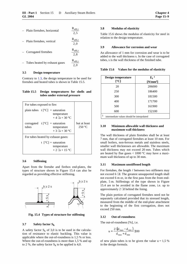
3.6 Stiffening
Apart from the firetube and firebox end-plates, the types of structure shown in Figure 15.4 can also be regarded as providing effective stiffening.
b ≥ 2 s
> 5
s
s
b ≥ 2 s
> 5
ss
Fig. 15.4 Types of structure for stiffening
3.7 Safety factor Sk
A safety factor Sk of 3,0 is to be used in the calcula-tion of resistance to elastic buckling. This value is applicable where the out-of-roundness is 1,5 % or less. Where the out-of-roundness is more than 1,5 % and up to 2 %, the safety factor Sk to be applied is 4,0.
3.8 Modulus of elasticity
Table 15.6 shows the modulus of elasticity for steel in relation to the design temperature.
3.9 Allowance for corrosion and wear
An allowance of 1 mm for corrosion and wear is to be added to the wall thickness s. In the case of corrugated tubes, s is the wall thickness of the finished tube.
Table 15.6 Values for the modulus of elasticity
Design temperature [°C]
Et 1 [N/mm2]
20
250
300
400
500
600
206000
186400
181500
171700
161900
152100 1 intermediate values should be interpolated
3.10 Minimum allowable wall thickness and maximum wall thickness
The wall thickness of plain firetubes shall be at least 7 mm, that of corrugated firetubes at least 10 mm. For small boilers, non-ferrous metals and stainless steels, smaller wall thicknesses are allowable. The maximum wall thickness may not exceed 20 mm. Tubes which are heated by flue gases < 1000 °C may have a maxi-mum wall thickness of up to 30 mm.
3.11 Maximum unstiffened length
For firetubes, the length between two stiffeners may not exceed 6 ⋅ d. The greatest unsupported length shall not exceed 6 m or, in the first pass from the front end-plate, 5 m. Stiffenings of the type shown in Figure 15.4 are to be avoided in the flame zone, i.e. up to approximately 2 ⋅ d behind the lining.
The plain portion of corrugated firetubes need not be separately calculated provided that its stressed length, measured from the middle of the end-plate attachment to the beginning of the first corrugation, does not exceed 250 mm.
3.12 Out-of-roundness
The out-of-roundness [%], i.e.
( )100
dd
dd2u
minmax
minmax ⋅+−⋅
=
of new plain tubes is to be given the value u = 1,5 % in the design formula.
In the case of used firetubes, the out-of-roundness is to be determined by measurements of the diameters according to Fig 15.5, i.e.
ua
d= ⋅ ⋅4
100
ad
Fig. 15.5 Determination of out-of-roundness
3.13 Firetube spacing
The clear distance between the firetube and boiler shell at the closest point shall be at least 100 mm. The distance between any two firetubes shall be at least 120 mm.
4. Dished endplates under internal and ex-ternal pressure
4.1 Scope
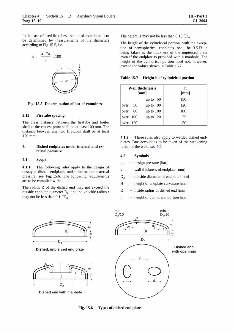
4.1.1 The following rules apply to the design of unstayed dished endplates under internal or external pressure, see Fig. 15.6. The following requirements are to be complied with:
The radius R of the dished end may not exceed the outside endplate diameter Da, and the knuckle radius r may not be less than 0,1 ⋅ Da.
The height H may not be less than 0,18 ⋅ Da.
The height of the cylindrical portion, with the excep-tion of hemispherical endplates, shall be 3.5 ⋅ s, s being taken as the thickness of the unpierced plate even if the endplate is provided with a manhole. The height of the cylindrical portion need not, however, exceed the values shown in Table 15.7.
Table 15.7 Height h of cylindrical portion
Wall thickness s[mm]
h[mm]
up to 50
over 50 up to 80
over 80 up to 100
over 100 up to 120
over 120
150
120
100
75
50
4.1.2 These rules also apply to welded dished end-plates. Due account is to be taken of the weakening factor of the weld, see 4.5.
4.2 Symbols
pc = design pressure [bar]
s = wall thickness of endplate [mm]
Da = outside diameter of endplate [mm]
H = height of endplate curvature [mm]
R = inside radius of dished end [mm]
h = height of cylindrical portion [mm]
min.Da/10
min.Da/10
R
H
r
d1d2
d1d2
Dished endwith openingsDished, unpierced end plate
Dished end with manhole
R
Da
H
rd
R
Da
H
r
s
s
s
Da
hh
h
Fig. 15.6 Types of dished end plates
Chapter 4 Page 15–10
Section 15 Auxiliary Steam Boilers III - Part 1GL 2004
D
d = diameter of opening measured along a line passing through the centres of the endplate and the opening. In the case of openings con-centric with the endplate, the maximum open-ing diameter [mm].
σzul = allowable stress, see 1.4 [N/mm2]
β = coefficient of stress in knuckle [-]
βo = coefficient of stress in spherical section [-]
v = weakening factor [-]
c = allowance for corrosion and wear [mm]
Et = modulus of elasticity at design temperature [N/mm2]
sA = necessary wall thickness at edge of opening [mm]
sS = wall thickness of branch pipe [mm]
b = supporting length of parent component [mm]
= width of ligament between two branch pipes [mm]
s = supporting length of branch pipe [mm]
's = internal projection of branch pipe [mm]
Ap = area subject to pressure [mm2]
Aσ = supporting cross-sectional area [mm2]
Sk = safety factor against elastic buckling [–]
S'k = safety factor against eleastic buckling at test pressure [–]
4.3 Design calculation for internal pressure
4.3.1 The necessary wall thickness is given by the expression:
sD p
vca c
zul= ⋅ ⋅
⋅ ⋅+β
σ40 (6)
The as built wall thickness of the cylindrical portion must be at least equal to the required wall thickness of a cylindrical shell without weakening.
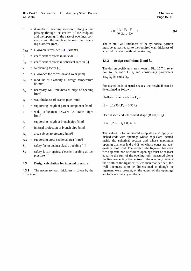
4.3.2 Design coefficients β and βo
The design coefficients are shown in Fig. 15.7 in rela-tion to the ratio H/Da and considering parameters
ad D s/ ⋅ and s/Da.
For dished ends of usual shapes, the height H can be determined as follows:
Shallow dished end (R = Da):
H ≈ 0,1935 ⋅ Da + 0,55 ⋅ s
Deep dished end, ellipsoidal shape (R = 0,8 Da):
H ≈ 0,255 ⋅ Da + 0,36 ⋅ s
The values β for unpierced endplates also apply to dished ends with openings whose edges are located inside the spherical section and whose maximum opening diameter is d ≤ 4 ⋅ s, or whose edges are ade-quately reinforced. The width of the ligament between two adjacent, non-reinforced openings must be at least equal to the sum of the opening radii measured along the line connecting the centres of the openings. Where the width of the ligament is less than that defined, the wall thickness is to be dimensioned as though no ligament were present, or the edges of the openings are to be adequately reinforced.
Fig. 15.7 Values of coefficient β for the design of dished ends
Chapter 4 Page 15–12
Section 15 Auxiliary Steam Boilers III - Part 1GL 2004
D
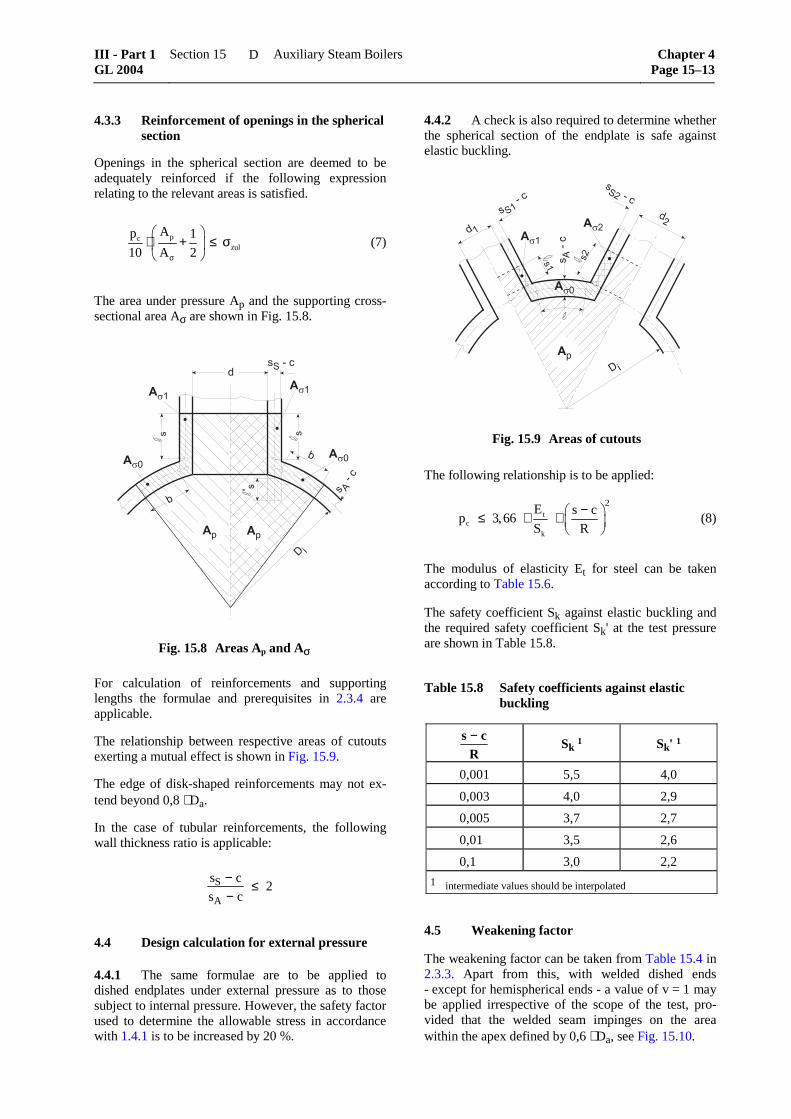
4.3.3 Reinforcement of openings in the spherical section
Openings in the spherical section are deemed to be adequately reinforced if the following expression relating to the relevant areas is satisfied.
pczul
Ap 1
10 A 2σ
⋅ + ≤ σ
(7)
The area under pressure Ap and the supporting cross-sectional area Aσ are shown in Fig. 15.8.
�
�! �!
���
������
���
��"�#��
�
$
$
� %�#�
�
� �
�
Fig. 15.8 Areas Ap and Aσ
For calculation of reinforcements and supporting lengths the formulae and prerequisites in 2.3.4 are applicable.
The relationship between respective areas of cutouts exerting a mutual effect is shown in Fig. 15.9.
The edge of disk-shaped reinforcements may not ex-tend beyond 0,8 ⋅ Da.
In the case of tubular reinforcements, the following wall thickness ratio is applicable:
s c
s cS
A
−−
≤ 2
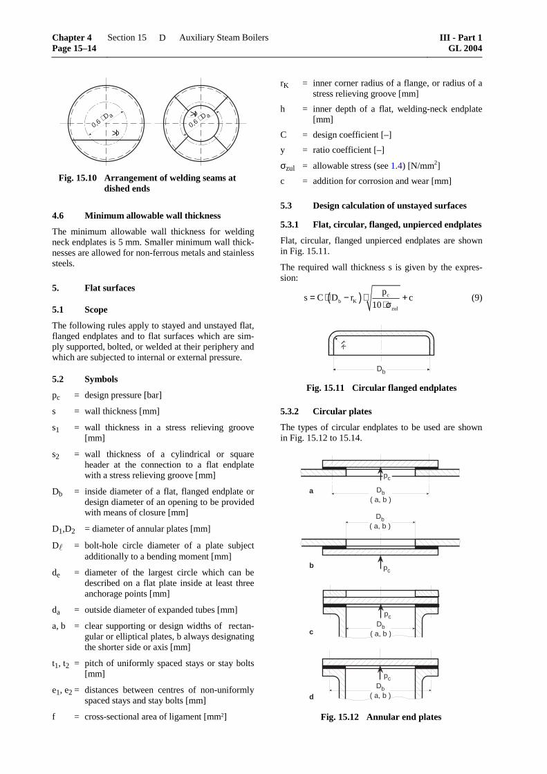
4.4 Design calculation for external pressure
4.4.1 The same formulae are to be applied to dished endplates under external pressure as to those subject to internal pressure. However, the safety factor used to determine the allowable stress in accordance with 1.4.1 is to be increased by 20 %.
4.4.2 A check is also required to determine whether the spherical section of the endplate is safe against elastic buckling.
�!
���
���
���� �
� "��#��
��
��
�"� �#��
��
� �
� %�#
��
Fig. 15.9 Areas of cutouts
The following relationship is to be applied:
tc
k
2E s c
p 3,66S R
− ≤ ⋅ ⋅
(8)
The modulus of elasticity Et for steel can be taken according to Table 15.6.
The safety coefficient Sk against elastic buckling and the required safety coefficient Sk' at the test pressure are shown in Table 15.8.
Table 15.8 Safety coefficients against elastic buckling
s cR−
Sk 1 Sk' 1
0,001 5,5 4,0
0,003 4,0 2,9
0,005 3,7 2,7
0,01 3,5 2,6
0,1 3,0 2,2
1 intermediate values should be interpolated
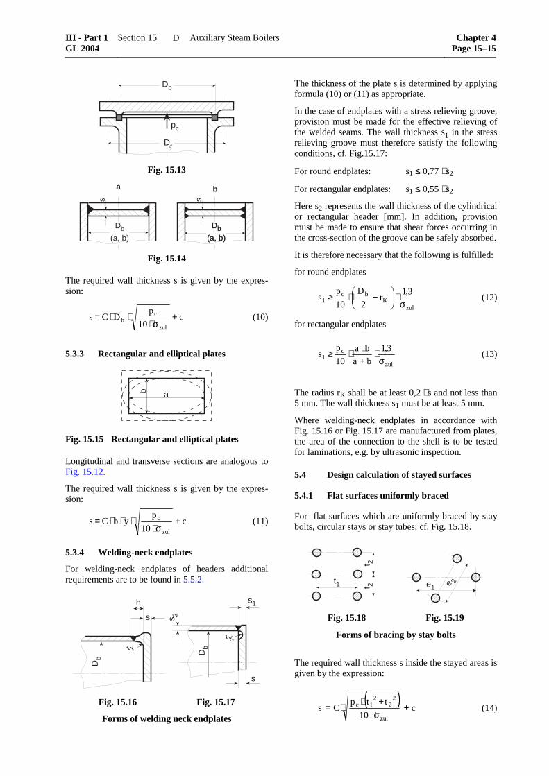
4.5 Weakening factor
The weakening factor can be taken from Table 15.4 in 2.3.3. Apart from this, with welded dished ends - except for hemispherical ends - a value of v = 1 may be applied irrespective of the scope of the test, pro-vided that the welded seam impinges on the area within the apex defined by 0,6 ⋅ Da, see Fig. 15.10.
Fig. 15.10 Arrangement of welding seams at dished ends
4.6 Minimum allowable wall thickness
The minimum allowable wall thickness for welding neck endplates is 5 mm. Smaller minimum wall thick-nesses are allowed for non-ferrous metals and stainless steels.
5. Flat surfaces
5.1 Scope
The following rules apply to stayed and unstayed flat, flanged endplates and to flat surfaces which are sim-ply supported, bolted, or welded at their periphery and which are subjected to internal or external pressure.
5.2 Symbols
pc = design pressure [bar]
s = wall thickness [mm]
s1 = wall thickness in a stress relieving groove [mm]
s2 = wall thickness of a cylindrical or square header at the connection to a flat endplate with a stress relieving groove [mm]
Db = inside diameter of a flat, flanged endplate or design diameter of an opening to be provided with means of closure [mm]
D1,D2 = diameter of annular plates [mm]
D = bolt-hole circle diameter of a plate subject additionally to a bending moment [mm]
de = diameter of the largest circle which can be described on a flat plate inside at least three anchorage points [mm]
da = outside diameter of expanded tubes [mm]
a, b = clear supporting or design widths of rectan-gular or elliptical plates, b always designating the shorter side or axis [mm]
t1, t2 = pitch of uniformly spaced stays or stay bolts [mm]
e1, e2 = distances between centres of non-uniformly spaced stays and stay bolts [mm]
f = cross-sectional area of ligament [mm2]
rK = inner corner radius of a flange, or radius of a stress relieving groove [mm]
h = inner depth of a flat, welding-neck endplate [mm]
Flat, circular, flanged unpierced endplates are shown in Fig. 15.11.
The required wall thickness s is given by the expres-sion:
( ) cb K
zul
ps C D r c
10= ⋅ − ⋅ +
⋅σ (9)
Db
rK
Fig. 15.11 Circular flanged endplates
5.3.2 Circular plates
The types of circular endplates to be used are shown in Fig. 15.12 to 15.14.
a
b
d
c
Db( a, b )
pc
Db( a, b )
pc
Db( a, b )
pc
Db( a, b )
pc
Fig. 15.12 Annular end plates
Chapter 4 Page 15–14
Section 15 Auxiliary Steam Boilers III - Part 1GL 2004
D
Db
D
pc
Fig. 15.13
Db(a, b)
s
Db
(a, b)
s
Db
(a, b)
a b
Fig. 15.14
The required wall thickness s is given by the expres-sion:
c10
pDCs
zul
cb +
σ⋅⋅⋅= (10)
5.3.3 Rectangular and elliptical plates
ab
Fig. 15.15 Rectangular and elliptical plates
Longitudinal and transverse sections are analogous to Fig. 15.12.
The required wall thickness s is given by the expres-sion:
c10
pybCs
zul
c +σ⋅
⋅⋅⋅= (11)
5.3.4 Welding-neck endplates
For welding-neck endplates of headers additional requirements are to be found in 5.5.2.
Db
h
s
r K
s1
Db
rK
s
s 2
Fig. 15.16 Fig. 15.17
Forms of welding neck endplates
The thickness of the plate s is determined by applying formula (10) or (11) as appropriate.
In the case of endplates with a stress relieving groove, provision must be made for the effective relieving of the welded seams. The wall thickness s1 in the stress relieving groove must therefore satisfy the following conditions, cf. Fig.15.17:
For round endplates: s1 ≤ 0,77 ⋅ s2
For rectangular endplates: s1 ≤ 0,55 ⋅ s2
Here s2 represents the wall thickness of the cylindrical or rectangular header [mm]. In addition, provision must be made to ensure that shear forces occurring in the cross-section of the groove can be safely absorbed.
It is therefore necessary that the following is fulfilled:
for round endplates
zul
Kbc
13,1
r2
D
10
ps
σ⋅
−⋅≥ (12)
for rectangular endplates
zul
c1
3,1
ba
ba
10
ps
σ⋅
+⋅⋅≥ (13)
The radius rK shall be at least 0,2 ⋅ s and not less than 5 mm. The wall thickness s1 must be at least 5 mm.
Where welding-neck endplates in accordance with Fig. 15.16 or Fig. 15.17 are manufactured from plates, the area of the connection to the shell is to be tested for laminations, e.g. by ultrasonic inspection.
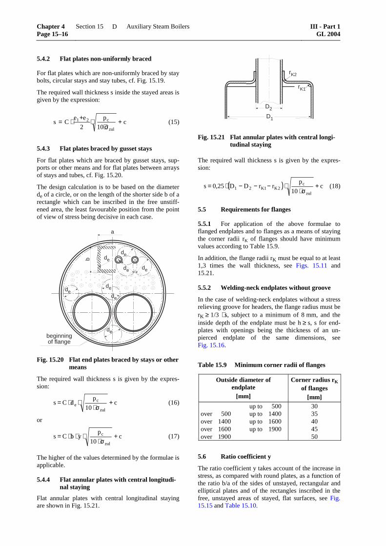
5.4 Design calculation of stayed surfaces
5.4.1 Flat surfaces uniformly braced
For flat surfaces which are uniformly braced by stay bolts, circular stays or stay tubes, cf. Fig. 15.18.
t1 t 2t 2
e1 e 2
Fig. 15.18 Fig. 15.19
Forms of bracing by stay bolts
The required wall thickness s inside the stayed areas is given by the expression:
For flat plates which are non-uniformly braced by stay bolts, circular stays and stay tubes, cf. Fig. 15.19.
The required wall thickness s inside the stayed areas is given by the expression:
c10
p
2
eeCs
zul
c21 +σ⋅
⋅+⋅= (15)
5.4.3 Flat plates braced by gusset stays
For flat plates which are braced by gusset stays, sup-ports or other means and for flat plates between arrays of stays and tubes, cf. Fig. 15.20.
The design calculation is to be based on the diameter de of a circle, or on the length of the shorter side b of a rectangle which can be inscribed in the free unstiff-ened area, the least favourable position from the point of view of stress being decisive in each case.
dede
de
de
de
de de
a
b
debeginningof flange
Fig. 15.20 Flat end plates braced by stays or other means
The required wall thickness s is given by the expres-sion:
c10
pdCs
zul
ce +
σ⋅⋅⋅= (16)
or
c10
pybCs
zul
c +σ⋅
⋅⋅⋅= (17)
The higher of the values determined by the formulae is applicable.
5.4.4 Flat annular plates with central longitudi-nal staying
Flat annular plates with central longitudinal staying are shown in Fig. 15.21.
D1
rK1
rK2
D2
Fig. 15.21 Flat annular plates with central longi-tudinal staying
The required wall thickness s is given by the expres-sion:
( ) c10
prrDD25,0s
zul
c2K1K21 +
σ⋅⋅−−−⋅= (18)
5.5 Requirements for flanges
5.5.1 For application of the above formulae to flanged endplates and to flanges as a means of staying the corner radii rK of flanges should have minimum values according to Table 15.9.
In addition, the flange radii rK must be equal to at least 1,3 times the wall thickness, see Figs. 15.11 and 15.21.
5.5.2 Welding-neck endplates without groove
In the case of welding-neck endplates without a stress relieving groove for headers, the flange radius must be rK ≥ 1/3 ⋅ s, subject to a minimum of 8 mm, and the inside depth of the endplate must be h ≥ s, s for end-plates with openings being the thickness of an un-pierced endplate of the same dimensions, see Fig. 15.16.
Table 15.9 Minimum corner radii of flanges
Outside diameter of endplate
[mm]
Corner radius rK of flanges
[mm] up to 500 over 500 up to 1400 over 1400 up to 1600 over 1600 up to 1900 over 1900
30 35 40 45 50
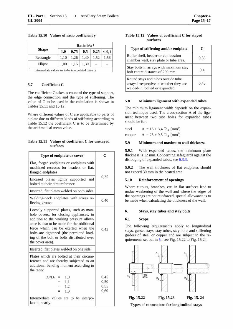
5.6 Ratio coefficient y
The ratio coefficient y takes account of the increase in stress, as compared with round plates, as a function of the ratio b/a of the sides of unstayed, rectangular and elliptical plates and of the rectangles inscribed in the free, unstayed areas of stayed, flat surfaces, see Fig. 15.15 and Table 15.10.
Chapter 4 Page 15–16
Section 15 Auxiliary Steam Boilers III - Part 1GL 2004
D
Table 15.10 Values of ratio coefficient y
Ratio b/a 1 Shape 1,0 0,75 0,5 0,25 ≤ 0,1
Rectangle 1,10 1,26 1,40 1,52 1,56
Ellipse 1,00 1,15 1,30 – – 1 intermediate values are to be interpolated linearly
5.7 Coefficient C
The coefficient C takes account of the type of support, the edge connection and the type of stiffening. The value of C to be used in the calculation is shown in Tables 15.11 and 15.12.
Where different values of C are applicable to parts of a plate due to different kinds of stiffening according to Table 15.12 the coefficient C is to be determined by the arithmetical mean value.
Table 15.11 Values of coefficient C for unstayed surfaces
Type of endplate or cover C
Flat, forged endplates or endplates with machined recesses for headers or flat, flanged endplates
Encased plates tightly supported and bolted at their circumference
Inserted, flat plates welded on both sides
0,35
Welding-neck endplates with stress re-lieving groove
0,40
Loosely supported plates, such as man-hole covers; for closing appliances, in addition to the working pressure allow-ance is also to be made for the additional force which can be exerted when the bolts are tightened (the permitted load-ing of the bolt or bolts distributed over the cover area).
Inserted, flat plates welded on one side
0,45
Plates which are bolted at their circum-ference and are thereby subjected to an additional bending moment according to the ratio:
D /Db = 1,0 = 1,1 = 1,2 = 1,3
Intermediate values are to be interpo-lated linearly.
0,45 0,50 0,55 0,60
Table 15.12 Values of coefficient C for stayed surfaces
Type of stiffening and/or endplate C
Boiler shell, header or combustionchamber wall, stay plate or tube area.
0,35
Stay bolts in arrays with maximum staybolt centre distance of 200 mm. 0,4
Round stays and tubes outside tubearrays irrespective of whether they arewelded-in, bolted or expanded.
0,45
5.8 Minimum ligament with expanded tubes
The minimum ligament width depends on the expan-sion technique used. The cross-section A of the liga-ment between two tube holes for expanded tubes should be for:
steel A = 15 + 3,4 ⋅ da [mm2]
copper A = 25 + 9,5 ⋅ da [mm2]
5.9 Minimum and maximum wall thickness
5.9.1 With expanded tubes, the minimum plate thickness is 12 mm. Concerning safeguards against the dislodging of expanded tubes, see 6.3.3.
5.9.2 The wall thickness of flat endplates should not exceed 30 mm in the heated area.
5.10 Reinforcement of openings
Where cutouts, branches, etc. in flat surfaces lead to undue weakening of the wall and where the edges of the openings are not reinforced, special allowance is to be made when calculating the thickness of the wall.
6. Stays, stay tubes and stay bolts
6.1 Scope
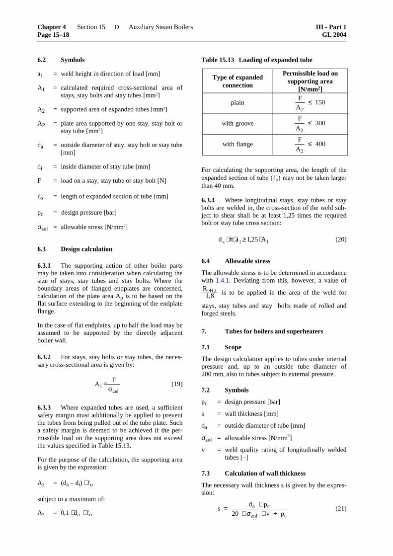
The following requirements apply to longitudinal stays, gusset stays, stay tubes, stay bolts and stiffening girders of steel or copper and are subject to the re-quirements set out in 5., see Fig. 15.22 to Fig. 15.24.
A1 = calculated required cross-sectional area of stays, stay bolts and stay tubes [mm2]
A2 = supported area of expanded tubes [mm2]
AP = plate area supported by one stay, stay bolt or stay tube [mm2]
da = outside diameter of stay, stay bolt or stay tube [mm]
di = inside diameter of stay tube [mm]
F = load on a stay, stay tube or stay bolt [N]
o = length of expanded section of tube [mm]
pc = design pressure [bar]
σzul = allowable stress [N/mm2]
6.3 Design calculation
6.3.1 The supporting action of other boiler parts may be taken into consideration when calculating the size of stays, stay tubes and stay bolts. Where the boundary areas of flanged endplates are concerned, calculation of the plate area Ap is to be based on the flat surface extending to the beginning of the endplate flange.
In the case of flat endplates, up to half the load may be assumed to be supported by the directly adjacent boiler wall.
6.3.2 For stays, stay bolts or stay tubes, the neces-sary cross-sectional area is given by:
zul
1F
Aσ
= (19)
6.3.3 Where expanded tubes are used, a sufficient safety margin must additionally be applied to prevent the tubes from being pulled out of the tube plate. Such a safety margin is deemed to be achieved if the per-missible load on the supporting area does not exceed the values specified in Table 15.13.
For the purpose of the calculation, the supporting area is given by the expression:
A2 = (da – di) ⋅ o
subject to a maximum of:
A2 = 0,1 ⋅ da ⋅ o
Table 15.13 Loading of expanded tube
Type of expandedconnection
Permissible load onsupporting area
[N/mm2]
plainF
A2150≤
with grooveF
A2300≤
with flangeF
A2400≤
For calculating the supporting area, the length of the expanded section of tube ( o) may not be taken larger than 40 mm.
6.3.4 Where longitudinal stays, stay tubes or stay bolts are welded in, the cross-section of the weld sub-ject to shear shall be at least 1,25 times the required bolt or stay tube cross section:
11a A25,1ad ⋅≥⋅π⋅ (20)
6.4 Allowable stress
The allowable stress is to be determined in accordance with 1.4.1. Deviating from this, however, a value of ReH t,
,1 8 is to be applied in the area of the weld for
stays, stay tubes and stay bolts made of rolled and forged steels.
7. Tubes for boilers and superheaters
7.1 Scope
The design calculation applies to tubes under internal pressure and, up to an outside tube diameter of 200 mm, also to tubes subject to external pressure.
7.2 Symbols
pc = design pressure [bar]
s = wall thickness [mm]
da = outside diameter of tube [mm]
σzul = allowable stress [N/mm2]
v = weld quality rating of longitudinally welded tubes [–]
7.3 Calculation of wall thickness
The necessary wall thickness s is given by the expres-sion:
sd p
v pa c
zul c= ⋅
⋅ ⋅ +20 σ (21)
Chapter 4 Page 15–18
Section 15 Auxiliary Steam Boilers III - Part 1GL 2004
D
7.4 Design temperature t
The design temperature is to be determined in accor-dance with 1.3.
In the case of once-through forced flow boilers, the calculation of the tube wall thicknesses is to be based on the maximum temperature expected in the individ-ual main sections of the boiler under operating condi-tions plus the necessary added temperature allow-ances.
7.5 Allowable stress
The allowable stress is to be determined in accordance with 1.4.1.
For tubes subject to external pressure, a value of ReH t,
,2 0 is to be applied.
7.6 Welding factor v
For longitudinally welded tubes, the value of v to be applied shall correspond to the approval test.
7.7 Wall thickness allowances
In the case of tubes subject to severe mechanical or chemical attack, an appropriate wall thickness allow-ance shall be agreed which shall be added to the wall thickness calculated by applying formula (21). The permissible minus tolerance on the wall thickness (see 1.1.2) need only be taken into consideration for tubes the outside diameter of which exceeds 76,1 mm.
7.8 Maximum wall thickness of boiler tubes
The wall thickness of intensely heated boiler tubes, e.g. where the temperature of the heating gas exceeds 800 °C, shall not be greater than 6,3 mm. This re-quirement may be dispensed with in special cases, e.g. for superheater support tubes.
8. Plain rectangular tubes and sectional headers
8.1 Symbols
pc = design pressure [bar]
s = wall thickness [mm]
2 ⋅ m = clear width of the rectangular tube parallel to the wall in question [mm], see Fig. 15.25
2 ⋅ n = clear width of the rectangular tube perpen-dicular to the wall in question [mm], see Fig. 15.25
Z = value according to formula (23) [mm2]
a = distance of relevant line of holes from centre line of side [mm]
t = pitch of holes [mm]
d = hole diameter [mm]
v = weakening factor for rows of holes under tensile stress [–]
v' = weakening factor for rows of holes under bending stress [–]
r = inner radius at corners [mm]
σzul = allowable stress [N/mm2]
8.2 Design calculation
8.2.1 The wall thickness is to be calculated for the centre of the side and for the ligaments between the holes. The maximum calculated wall thickness shall govern the wall thickness of the entire rectangular tube.
The following method of calculation is based on the assumption that the tube connection stubs have been properly mounted, so that the wall is adequately stiff-ened.
8.2.2 The required wall thickness is given by the expression:
c c
zul zul
p n 4,5 Z ps
20 v 10 v '
⋅ ⋅ ⋅= +
⋅σ ⋅ ⋅σ ⋅ (22)
If there are several different rows of holes, the neces-sary wall thickness is to be determined for each row.
8.2.3 Z is calculated by applying the formula
( )3 3
2 21 m n 1Z m a
3 m n 2
+= ⋅ − ⋅ −+
(23)
8.3 Weakening factor v
8.3.1 If there is only one row of holes, or if there are several parallel rows not staggered in relation to each other, the weakening factors v and v' are to be determined as follows:
t dv
t
−=
v vt d
t' = = −
for holes where d < 0,6 ⋅ m
vt m
t'
,= − ⋅0 6 for holes where d ≥ 0,6 ⋅ m
8.3.2 In determining the values of v and v' for elliptical holes, d is to be taken as the clear width of the holes in the longitudinal direction of the rectangu-lar tube. However, for the purpose of deciding which formula is to be used for determining v', the value of d in the expressions d ≥ 0,6 ⋅ m and d < 0,6 ⋅ m is to be the inner diameter of the hole perpendicular to the longitudinal axis.
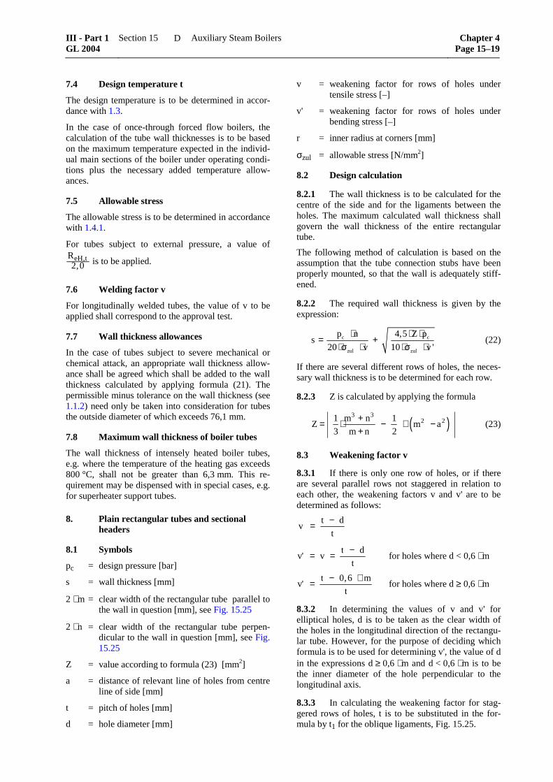
8.3.3 In calculating the weakening factor for stag-gered rows of holes, t is to be substituted in the for-mula by t1 for the oblique ligaments, Fig. 15.25.
8.3.4 For oblique ligaments, the value of Z to be used in formula (22) is that determined by applying formula (23), with a = 0, and multiplying by cos α.
�
�
� �
�
� ��
��
���
���
�
�
�
�
�
�
�
Fig. 15.25 Arrangement of staggered rows of holes
8.4 Stress at corners
In order to avoid undue stresses at corners, the follow-ing conditions are to be satisfied:
r ≥ 1/2 ⋅ s, subject to a minimum of:
3 mm for rectangular tubes with a clear width of up to 50 mm.
8 mm for rectangular tubes with a clear width of 80 mm or over.
Intermediate values are to be interpolated linearly. The radius shall be governed by the arithmetical mean value of the nominal wall thicknesses on both sides of the corner. The wall thickness at corners may not be less than the wall thickness determined by applying formula (22).
8.5 Minimum wall thickness and ligament width
8.5.1 The minimum wall thickness with expanded tubes shall be 14 mm.
8.5.2 The width of a ligament between two open-ings or tube holes may not be less than ¼ of the dis-tance between the tube centres.
9. Straps and girders
9.1 Scope
The following requirements apply to steel girders used for stiffening of flat plates.
9.2 General
The supporting girders are to be properly welded to the combustion chamber crown at all points. They are to be arranged in such a way that the welds can be competently executed and the circulation of water is not obstructed.
9.3 Symbols
pc = design pressure [bar]
F = load carried by one girder [N]
e = distance between centre lines of girders [mm]
= free length between girder supports [mm]
b = thickness of girder [mm]
h = height of girder [mm]
W = section modulus of one girder [mm3]
M = bending moment acting on girder at given load [Nmm]
z = coefficient for section modulus [–]
σzul = allowable stress, see 1.4 [N/mm2]
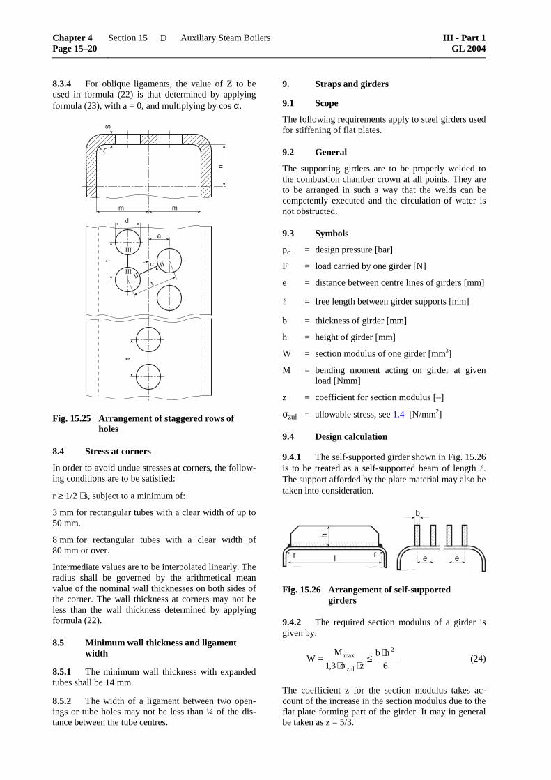
9.4 Design calculation
9.4.1 The self-supported girder shown in Fig. 15.26 is to be treated as a self-supported beam of length . The support afforded by the plate material may also be taken into consideration.
r l
h
b
e er
Fig. 15.26 Arrangement of self-supported girders
9.4.2 The required section modulus of a girder is given by:
6
hb
z3,1
MW
2
zul
max ⋅≤⋅σ⋅
= (24)
The coefficient z for the section modulus takes ac-count of the increase in the section modulus due to the flat plate forming part of the girder. It may in general be taken as z = 5/3.
Chapter 4 Page 15–20
Section 15 Auxiliary Steam Boilers III - Part 1GL 2004
D
For the height h, a value not exceeding 8 ⋅ b is to be inserted in the formula.
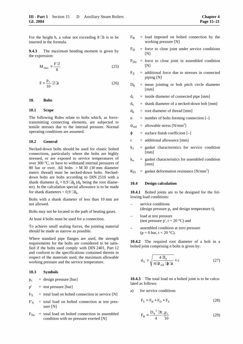
9.4.3 The maximum bending moment is given by the expression:
8
FM max
⋅= (25)
e10
pF c ⋅⋅= (26)
10. Bolts
10.1 Scope
The following Rules relate to bolts which, as force-transmitting connecting elements, are subjected to tensile stresses due to the internal pressure. Normal operating conditions are assumed.
10.2 General
Necked-down bolts should be used for elastic bolted connections, particularly where the bolts are highly stressed, or are exposed to service temperatures of over 300 °C, or have to withstand internal pressures of 80 bar or over. All bolts > M 30 (30 mm diameter metric thread) must be necked-down bolts. Necked-down bolts are bolts according to DIN 2510 with a shank diameter ds = 0,9 ⋅ dk (dk being the root diame-ter). In the calculation special allowance is to be made for shank diameters < 0,9 ⋅ dk.
Bolts with a shank diameter of less than 10 mm are not allowed.
Bolts may not be located in the path of heating gases.
At least 4 bolts must be used for a connection.
To achieve small sealing forces, the jointing material should be made as narrow as possible.
Where standard pipe flanges are used, the strength requirements for the bolts are considered to be satis-fied if the bolts used comply with DIN 2401, Part 12 and conform to the specifications contained therein in respect of the materials used, the maximum allowable working pressure and the service temperature.
10.3 Symbols
pc = design pressure [bar]
p' = test pressure [bar]
FS = total load on bolted connection in service [N]
F'S = total load on bolted connection at test pres-sure [N]
FSo = total load on bolted connection in assembled condition with no pressure exerted [N]
FB = load imposed on bolted connection by the working pressure [N]
FD = force to close joint under service conditions [N]
FDo = force to close joint in assembled condition [N]
FZ = additional force due to stresses in connected piping [N]
Db = mean jointing or bolt pitch circle diameter [mm]
di = inside diameter of connected pipe [mm]
ds = shank diameter of a necked-down bolt [mm]
dk = root diameter of thread [mm]
n = number of bolts forming connection [–]
σzul = allowable stress [N/mm2]
ϕ = surface finish coefficient [–]
c = additional allowance [mm]
k1 = gasket characteristics for service condition [mm]
ko = gasket characteristics for assembled condition [mm]
KD = gasket deformation resistance [N/mm2]
10.4 Design calculation
10.4.1 Bolted joints are to be designed for the fol-lowing load conditions:
– service conditions (design pressure pc and design temperature t),
– load at test pressure (test pressure p', t = 20 °C) and
– assembled condition at zero pressure (p = 0 bar, t = 20 °C).
10.4.2 The required root diameter of a bolt in a bolted joint comprising n bolts is given by:
cn
F4d
zul
Sk +
⋅ϕ⋅σ⋅π⋅
= (27)
10.4.3 The total load on a bolted joint is to be calcu-lated as follows:
Where the arrangement of bolts deviates widely from the circular, due allowance is to be made for the special stresses occurring.
The additional force FZ due to connected piping must be calculated from the stresses present in these pipes. FZ is 0 in the case of bolted joints with no connected pipes. Where connecting pipes are installed in a normal manner and the service temperatures are < 400 °C, FZ may be determined, as an approximation, by applying the expression:
FZ ≈ d pi c
2
4 10
⋅ ⋅π
b) for the test pressure:
DS B Z
c
Fp 'F ' F F
p 1,2 = ⋅ + +
(31)
For calculating the root diameter of the thread, FS is to be substituted by FS' in formula (27).
c) for the zero-pressure, assembled condition:
F F FSo Do Z= + (32)
F D k KDo b o D= ⋅ ⋅ ⋅π (33)
For calculating the root diameter of the thread, FS is to be substituted by FSo in formula (27).
In the zero-pressure, assembled condition, the force FDo is to be exerted on the bolts during as-sembly to effect an intimate union with the jointing material and to close the gap at the flange bearing surfaces.
If the force exerted on the assembly FDo is greater than FS, it may be replaced by the fol-lowing, where malleable jointing materials with or without metal elements are used:
Do Do S DoF ' 0, 2 F 0,8 F F= ⋅ + ⋅ ⋅ (34)
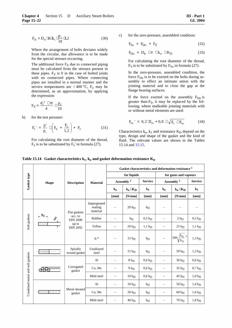
Characteristics ko, k1 and resistance KD depend on the type, design and shape of the gasket and the kind of fluid. The relevant values are shown in the Tables 15.14 and 15.15.
Table 15.14 Gasket characteristics k1, ko and gasket deformation resistance KD
Gasket characteristics and deformation resistance 1
for liquids for gases and vapours
Assembly 2 Service Assembly 2 Service
ko ko ⋅ KD k1 ko ko ⋅ KD k1 Gas
ket t
ype
Shape Description Material
[mm] [N/mm] [mm] [mm] [N/mm] [mm]
Impregnated sealing material
–
20 bD
bD
–
–
–
Rubber – bD 0,5 bD – 2 bD 0,5 bD
Teflon – 20 bD 1,1 bD – 25 bD 1,1 bD
Soft
gas
kets
Flat gaskets acc. to
DIN 2690 up to
DIN 2692
It 4
–
15 bD
bD
–
D
D
h
b200 3
1,3 bD
Spirally
wound gasket Unalloyed
steel – 15 bD bD – 50 bD 1,3 bD
Al – 8 bD 0,6 bD – 30 bD 0,6 bD
Cu, Ms – 9 bD 0,6 bD – 35 bD 0,7 bD
Corrugated gasket
Mild steel – 10 bD 0,6 bD – 45 bD 1,0 bD
Al – 10 bD bD – 50 bD 1,4 bD
Cu, Ms – 20 bD bD – 60 bD 1,6 bD
Com
bine
d m
etal
and
sof
t gas
kets
Metal-sheated
gasket
Mild steel – 40 bD bD – 70 bD 1,8 bD
Chapter 4 Page 15–22
Section 15 Auxiliary Steam Boilers III - Part 1GL 2004
D
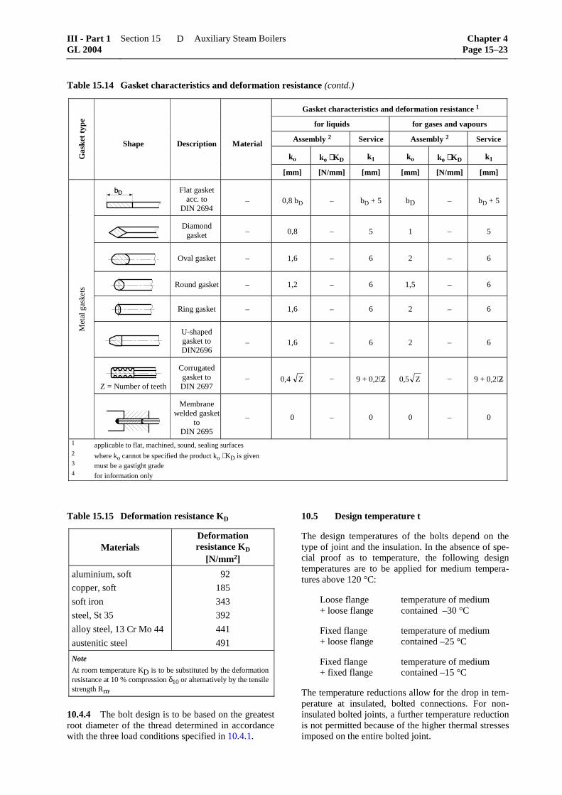
Table 15.14 Gasket characteristics and deformation resistance (contd.)
Gasket characteristics and deformation resistance 1
for liquids for gases and vapours
Assembly 2 Service Assembly 2 Service
ko ko ⋅ KD k1 ko ko ⋅ KD k1 Gas
ket
type
Shape Description Material
[mm] [N/mm] [mm] [mm] [N/mm] [mm]
Flat gasket acc. to
DIN 2694 – 0,8 bD – bD + 5 bD – bD + 5
Diamond
gasket – 0,8 – 5 1 – 5
Oval gasket – 1,6 – 6 2 – 6
Round gasket – 1,2 – 6 1,5 – 6
Ring gasket – 1,6 – 6 2 – 6
U-shaped gasket to DIN2696
– 1,6 – 6 2 – 6
Z = Number of teeth
Corrugated gasket to DIN 2697
– Z4,0 – 9 + 0,2⋅Z Z5,0
– 9 + 0,2⋅Z
Met
al g
aske
ts
Membrane welded gasket
to DIN 2695
– 0 – 0 0 – 0
1 applicable to flat, machined, sound, sealing surfaces 2 where ko cannot be specified the product ko ⋅ KD is given 3 must be a gastight grade 4 for information only
Table 15.15 Deformation resistance KD
Materials Deformation resistance KD
[N/mm2]
aluminium, soft
copper, soft
soft iron
steel, St 35
alloy steel, 13 Cr Mo 44
austenitic steel
92
185
343
392
441
491
Note
At room temperature KD is to be substituted by the deformation resistance at 10 % compression δ10 or alternatively by the tensile strength Rm.
10.4.4 The bolt design is to be based on the greatest root diameter of the thread determined in accordance with the three load conditions specified in 10.4.1.
10.5 Design temperature t
The design temperatures of the bolts depend on the type of joint and the insulation. In the absence of spe-cial proof as to temperature, the following design temperatures are to be applied for medium tempera-tures above 120 °C:
Loose flange + loose flange
temperature of medium contained –30 °C
Fixed flange + loose flange
temperature of medium contained –25 °C
Fixed flange + fixed flange
temperature of medium contained –15 °C
The temperature reductions allow for the drop in tem-perature at insulated, bolted connections. For non-insulated bolted joints, a further temperature reduction is not permitted because of the higher thermal stresses imposed on the entire bolted joint.
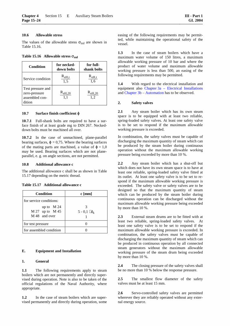
The values of the allowable stress σzul are shown in Table 15.16.
Table 15.16 Allowable stress σzul
Condition for necked-down bolts
for full- shank bolts
Service condition ReH t,
,1 5
ReH t,,1 6
Test pressure and zero-pressure assembled con-dition
ReH,,
201 1
ReH,
,20
1 2
10.7 Surface finish coefficient ϕ
10.7.1 Full-shank bolts are required to have a sur-face finish of at least grade mg to DIN 267. Necked-down bolts must be machined all over.
10.7.2 In the case of unmachined, plane-parallel bearing surfaces, ϕ = 0,75. Where the bearing surfaces of the mating parts are machined, a value of ϕ = 1,0 may be used. Bearing surfaces which are not plane-parallel, e. g. on angle sections, are not permitted.
10.8 Additional allowance c
The additional allowance c shall be as shown in Table 15.17 depending on the metric thread.
Table 15.17 Additional allowance c
Condition c [mm]
for service conditions:
up to M 24 M 27 up to M 45 M 48 and over
3 5 - 0,1 ⋅ dk
1
for test pressure 0
for assembled condition 0
E. Equipment and Installation
1. General
1.1 The following requirements apply to steam boilers which are not permanently and directly super-vised during operation. Note is also to be taken of the official regulations of the Naval Authority, where appropriate.
1.2 In the case of steam boilers which are super-vised permanently and directly during operation, some
easing of the following requirements may be permit-ted, while maintaining the operational safety of the vessel.
1.3 In the case of steam boilers which have a maximum water volume of 150 litres, a maximum allowable working pressure of 10 bar and where the product of water volume and maximum allowable working pressure is less than 500, an easing of the following requirements may be permitted.
1.4 With regard to the electrical installation and equipment also Chapter 3a – Electrical Installations and Chapter 3b – Automation has to be observed.
2. Safety valves
2.1 Any steam boiler which has its own steam space is to be equipped with at least two reliable, spring-loaded safety valves. At least one safety valve is to be set to respond if the maximum allowable working pressure is exceeded.
In combination, the safety valves must be capable of discharging the maximum quantity of steam which can be produced by the steam boiler during continuous operation without the maximum allowable working pressure being exceeded by more than 10 %.
2.2 Any steam boiler which has a shut-off but which does not have its own steam space is to have at least one reliable, spring-loaded safety valve fitted at its outlet. At least one safety valve is to be set to re-spond if the maximum allowable working pressure is exceeded. The safety valve or safety valves are to be designed so that the maximum quantity of steam which can be produced by the steam boiler during continuous operation can be discharged without the maximum allowable working pressure being exceeded by more than 10 %.
2.3 External steam drums are to be fitted with at least two reliable, spring-loaded safety valves. At least one safety valve is to be set to respond if the maximum allowable working pressure is exceeded. In combination, the safety valves must be capable of discharging the maximum quantity of steam which can be produced in continuous operation by all connected steam generators without the maximum allowable working pressure of the steam drum being exceeded by more than 10 %.
2.4 The closing pressure of the safety valves shall be no more than 10 % below the response pressure.
2.5 The smallest flow diameter of the safety valves must be at least 15 mm.
2.6 Servo-controlled safety valves are permitted wherever they are reliably operated without any exter-nal energy source.
Chapter 4 Page 15–24
Section 15 Auxiliary Steam Boilers III - Part 1GL 2004
E
2.7 The safety valves are to be fitted to the satu-rated steam part or, in the case of steam boilers which do not have their own steam space, to the steam-water outlet of the boiler.
2.8 Steam may not be supplied to the safety valves through pipes in which water may collect.
2.9 Safety valves must be easily accessible and capable of being released safely during operation.
2.10 Safety valves are to be designed so that no binding or jamming of moving parts is possible even when heated to different temperatures. Seals which may prevent the operation of the safety valve due to frictional forces are not permitted.
2.11 Safety valves are to be set in such a way as to prevent unauthorized alteration.
2.12 Pipes or valve housings must have a drain facility, which has no shut-off capability fitted at the lowest point on the blow-off side.
2.13 Combined blow-off lines from several safety valves may not unduly impair the blow-off capability. The discharging mediums are to be drained away safely.
3. Water level indicators
3.1 Steam boilers which have their own steam space are to be fitted with two devices giving a direct reading of the water level.
3.2 Steam boilers which have their own steam space heated by exhaust gases and where the tempera-ture does not exceed 400 °C, are to be fitted with at least one device giving a direct reading of the water level.
3.3 External steam drums of boilers which do not have their own steam space are to be fitted with two devices giving a direct reading of the water level.
3.4 Cylindrical glass water level gauges are not permitted.
3.5 The water level indicators are to be fitted so that a reading of the water level is possible when the ship is heeling and during the motion of the ship when it is at sea. The limit for the lower visual range must be at least 30 mm above the highest flue, but at least 30 mm below the lowest water level. The lowest water level may not be above the centre of the visual range. The water level indicators must be well illuminated and visible from the boiler control station.
3.6 The connection pipes between steam genera-tor and water level indicators must have an inner di-ameter of at least 20 mm. They must be run in such a way that there are no sharp bends in order to avoid
water and steam traps, and must be protected from the effects of the heated gases and against cooling.
Where water level indicators are linked by means of common connection lines or where the connection pipes on the water side are longer than 750 mm, the connection pipes on the water side must have an inner diameter of at least 40 mm.
3.7 Water level indicators are to be connected to the water and steam chamber of the boiler by means of easily accessible, simple to control and quick-acting shut-off devices.
3.8 The devices used for blowing through the water level indicators must be designed so that they are safe to operate and so that blow-through can be monitored. The discharging media are to be drained away safely.
3.9 Remote water level indicators and display equipment of a suitable type to give an indirect read-ing may be allowed as additional display devices.
3.10 In place of water level indicators, once-through forced flow boilers must be fitted with two mutually independent devices which trip an alarm as soon as water flow shortage is detected. An automatic device to shut down the heating system may be pro-vided in place of the second warning device.
3.11 The cocks and valves of the water level indi-cators which cannot be directly reached by hand from floor plates or a control platform must have a control facility using pull rods or chain pulls.
4. Pressure gauges
4.1 At least one pressure gauge directly con-nected to the steam space is to be fitted on each boiler. The maximum allowable working pressure is to be marked on the dial by means of a permanent and eas-ily visible red mark.
4.2 At least one additional pressure indicator having a sensor independent from the pressure gauge has to be located at the machinery control centre or at some other appropriate site.
4.3 Where several steam boilers are incorporated on one ship, the steam chambers of which are linked together, one pressure gauge is sufficient at the ma-chinery control centre or at some other suitable loca-tion, in addition to the pressure gauges on each boiler.
4.4 The pipe to the pressure gauge must have a water trap and must be of a blow-off type. A connec-tion for a test gauge must be installed close to the pressure gauge. In the case of pressure gauges which are set off at a lower position the test connection must be provided close to the pressure gauge and also close to the connection piece of the pressure gauge pipe.
4.5 Pressure gauges are to be protected against radiant heat and must be well illuminated.
5. Temperature gauges
5.1 A temperature gauge is to be fitted to the flue gas outlet of fired steam boilers.
5.2 Temperature gauges are to be fitted to the exhaust gas inlet and outlet of steam boilers heated by exhaust gas.
5.3 Temperature gauges must be fitted at the outlets from superheaters or superheater sections, at the inlet and outlet of attemporators, and also at the outlet of once-through forced flow boilers, where this is necessary to assess the behaviour of the materials used.
6. Regulating devices (controllers)
6.1 With the exception of boilers which are heated by exhaust gas, steam boilers are to be operated with rapid-control, automatic firing systems. The con-trol facility must be capable of safely controlling the scope of potential load changes so that the steam pres-sure and the temperature of the steam stay within safe limits and the supply of feed water is guaranteed.
6.2 Steam pressure must be automatically regu-lated by controlling the supply of heat. The steam pressure of boilers heated by exhaust gas may also be regulated by condensing the excess steam.
6.3 In the case of boilers which have a specified minimum water level, the water level must be regu-lated automatically by controlling the supply of feed water.
6.4 In case of forced-circulation boilers whose heating surface consists of a coiled pipe, and in case of once-through forced flow boilers, the supply of feed water may be regulated as a function of fuel supply.
7. Monitoring devices (alarms)
7.1 A warning device is to be fitted which is tripped when the specified maximum water level is exceeded.
7.2 In exhaust-gas heated boilers, a warning device is to be fitted which is tripped before the maxi-mum allowable working pressure is reached.
7.3 In exhaust-gas heated boilers with a specified minimum water level, a warning device is to be fitted which is tripped when the water falls below this level.
7.4 Exhaust gas boilers with finned tubes are to have a temperature monitor fitted in the exhaust gas pipe which trips an alarm in the event of fire, see Chapter 3b – Automation.
7.5 Where oil or grease may get into the steam or condensate system, a suitable automatic and continu-ously operating unit is to be installed which trips an alarm and cuts off the feed water supply if the concen-tration at which boiler operation is put at risk is ex-ceeded.
7.6 Where acids, lyes or seawater may get into the steam or condensate system, a suitable automatic and continuously operating unit is to be installed which trips an alarm and cuts off the feed water sup-ply if the concentration at which boiler operation is put at risk is exceeded.
7.7 Function testing of the monitoring devices must be possible, even during operation, if an equiva-lent degree of safety is not attained by self-monitoring of the equipment.
7.8 The monitoring devices must trip visual and audible fault warnings in the boiler room or in the machinery control centre or any other suitable site. See Chapter 3b – Automation.
8. Safety devices (limiters)
8.1 The suitability of safety devices for marine use is to be proven by type testing.
The safety devices must be suitable for the use on steam boilers on ships.
8.2 Fired boilers are to be equipped with a reli-able pressure limiter which cuts out and interlocks the firing system before the maximum allowable working pressure is reached.
8.3 In steam boilers where a highest flue is speci-fied at the heating surface, two reliable, mutually independent water level limiters must respond to cut out and interlock the firing system when the water falls below the specified minimum water level.
The water level limiter must also be independent of the water level control devices.
8.4 The receptacles for water level limiters lo-cated outside the boiler must be connected to the boiler by means of lines which have a minimum inner diameter of 20 mm. Shut-off devices in these lines must have a nominal diameter of at least 20 mm and must indicate their open or closed position. Where water level limiters are connected by means of com-mon connection lines, the connection pipes on the water side must have an inner diameter of at least 40 mm.
Operation of the firing system may only be possible when the shut-off devices are open or else, after clo-sure, the shut-off devices must reopen automatically and in a reliable manner.
Chapter 4 Page 15–26
Section 15 Auxiliary Steam Boilers III - Part 1GL 2004
E
Water level limiter receptacles which are located out-side the boiler are to be designed in such a way that a compulsory and periodic blow-through of the recepta-cles and lines is carried out.
8.5 In the case of forced-circulation boilers with a specified lowest water level, two reliable, mutually independent safety devices must be fitted in addition to the requisite water level limiters, which will cut out and interlock the heating system in the event of any unacceptable reduction in water circulation.
8.6 In the case of forced-circulation boilers where the heating surface consists of a single coiled pipe and of once-through forced flow boilers, two reliable, mutually independent safety devices must be fitted in place of the water level limiters in order to provide secure means of preventing any excessive heating of the heating surfaces by cutting out and interlocking the firing system.
8.7 The safety devices must trip visual and audi-ble alarms in the boiler room or in the machinery control room or any other appropriate site, see Chapter 3b – Automation.
8.8 The electrical devices associated with the limiters are to be designed in accordance with the closed-circuit principle so that, even in the event of a power failure, the limiters will cut out and interlock the systems unless an equivalent degree of safety is achieved by other means.
8.9 To reduce the effects due to swell, water level limiters can be fitted with a delay function provided that this does not cause a dangerous drop in the water level.
8.10 The electrical interlocking of the firing sys-tem following tripping by the safety devices may only be cancelled out at the firing system control panel itself.
8.11 If an equivalent degree of safety cannot be achieved by self-monitoring the equipment, the safety devices must be subjected to operational testing even during operation. In this case, the operational testing of water level limiters must be carried out without the surface of the water dropping below the lowest water level.
8.12 For details of additional requirements relating to once-through forced flow boilers, see 3.10.
9. Feed and circulation devices
9.1 For details of boiler feed and circulation devices, see Section 8, F. The following requirements are also to be noted:
9.2 The feed devices are to be fitted to the steam boiler in such a way that it cannot be drained lower
than to a level of 50 mm above the highest flue when the non-return valve is not tight.
9.3 The feed water is to be introduced into the boiler in such a way as to prevent damage occurring to the boiler walls and to heated surfaces.
10. Shut-off devices
10.1 Each steam boiler must be capable of being shut off from all connected pipes. The shut-off devices are to be installed as close as possible to the boiler walls and must operate without risk.
10.2 Where several boilers which have different maximum allowable working pressures deliver their steam into common lines, it is necessary to ensure that the maximum working pressure allowable for each boiler cannot be exceeded in any of the boilers.
10.3 Where several boilers are connected by common pipes and the shut-off devices for steam, feed and drain lines are welded to the boiler, two tandem shut-off devices with an interposed release device are to be fitted for safety reasons while the boilers are running. The shut-off devices are to be protected against unauthorized operation.
11. Scum removal, sludge removal, drain and sampling devices
11.1 Boilers and external steam drums are to be fitted with devices for draining and sludge removal. Where necessary, boilers are to be fitted with a scum removal device.
11.2 Drain devices and their connections must be protected against effects of the heating gases and ca-pable of being operated without risk. Self-closing sludge removal valves must be lockable when closed or alternatively an additional shut-off device is to be fitted in the pipe.
11.3 Where the scum removal, sludge removal or drain lines from several boilers are combined, a non-return valve is to be fitted in the individual boiler lines.
11.4 The scum removal, sludge removal or drain lines, plus valves and fittings, are to be designed to allow for the maximum allowable working pressure of the boiler.
11.5 With the exception of once-through forced flow boilers, devices for taking samples from the water contained in the boiler are to be fitted to steam boilers.
11.6 Scum removal, sludge removal, drain and sampling devices must be capable of safe operation. The media being discharged are to be drained away safely.
12.1 A name plate is to be permanently affixed to each steam boiler, displaying the following informa-tion:
– manufacturer
– serial number and year of construction
– maximum allowable working pressure [bar]
– steam production [kg/h] or [t/h]
– permitted temperature of steam [°C] provided that the boiler is fitted with no shut-off capabil-ity
12.2 The name plate must be permanently attached to the largest part of the boiler or to the boiler frame so that it is visible.
13. Valves and fittings
13.1 Materials
Valves and fittings for boilers must be made of ductile materials as specified in Table 15.1 and all their com-ponents must be able to withstand the loads imposed in operation, in particular thermal loads and possible stresses due to vibration. Grey cast iron may be used within the limits specified in Table 15.1, but may not be employed for valves and fittings which are sub-jected to dynamic loads, e.g. safety valves and blow-off valves.
Testing of materials for valves and fittings is to be carried out as specified in Table 15.2.
13.2 Design
Care is to be taken to ensure that the bodies of shut-off gate valves cannot be subjected to unduly high pres-sure due to heating of the enclosed water. Valves with screw-on bonnets must be safeguarded to prevent unintentional loosening of the bonnet.
13.3 Pressure and tightness tests
13.3.1 All valves and fittings are to be subjected to a hydrostatic pressure test at 1,5 times the nominal pres-sure before they are fitted. Valves and fittings for which no nominal pressure has been specified are to be tested at twice the working pressure. In this case, the safety factor in respect of the 20 °C yield strength value may not fall below 1,1.
13.3.2 The sealing efficiency of the closed valve is to be tested at the nominal pressure or at 1,1 times the working pressure, as applicable.
13.3.3 Pressure test and tightness test of valves and fittings shall be carried out in the presence of the GL Surveyor.
14. Installation of boilers
14.1 Mounting
Boilers must be installed in the ship with care and must be secured to ensure that they cannot be dis-placed by any of the circumstances arising when the ship is at sea. Means are to be provided to accommo-date the thermal expansion of the boiler in service. Boilers and their seatings must be easily accessible from all sides or must be easily rendered so.
14.2 Fire precautions
For fire precautions see Section 9.
F. Testing of Boilers
1. Constructional test
After completion, boilers are to undergo a construc-tional test.
The constructional test includes verification that the boiler agrees with the approved drawing and is of satisfactory construction. For this purpose, all parts of the boiler must be accessible to allow adequate inspec-tion. If necessary, the constructional test is to be per-formed at separate stages of manufacture. The follow-ing documents are to be presented: material test cer-tificates covering the materials used, reports on the non-destructive testing of welds and, where applica-ble, the results of tests of workmanship and proof of the heat treatment applied.
2. Hydrostatic pressure tests
2.1 A hydrostatic pressure test is to be carried out on the boiler before refractory, insulation and casing are fitted. Where only some of the component parts are sufficiently accessible to allow proper visual in-spection, the hydrostatic pressure test may be per-formed in stages. Boiler surfaces must withstand the test pressure without leaking or suffering permanent deformation.
2.2 The test pressure is generally required to be 1,5 times the maximum allowable working pressure, see A.4.2 In case the maximum allowable working pressure is less than 2 bar the test pressure has to be at least 1 bar higher than the maximum allowable work-ing pressure.
2.3 In case of once-through forced flow boilers, the test pressure must be at least 1,1 times the water inlet pressure when operating at the maximum allow-able working pressure and maximum steam output. In the event of danger that parts of the boiler might be subjected to stresses exceeding 90 % of the yield strength, the hydrostatic test may be performed in separate sections. The maximum allowable working pressure is then deemed to be the pressure for which the particular part of the boiler has been designed.
Chapter 4 Page 15–28
Section 15 Auxiliary Steam Boilers III - Part 1GL 2004
F
2.4 For boiler parts subject to internal and exter-nal pressures which invariably occur simultaneously in service, the test pressure depends on the differential pressure. In these circumstances, however, the test pressure should at least be equal to 1,5 times the de-sign pressure specified in D.1.2.4.
3. Constructional test and hydrostatic pressure test shall be carried out in the presence of the GL Surveyor respectively.
G. Hot Water Generators
1. Design
Hot water generators with a permissible discharge temperature of > 120 °C, which are heated by liquid fuels or by exhaust gases or electrically are to be
treated for materials, design calculations and manufac-turing in a manner analogous to boilers. The materials, design calculations and manufacturing principles for hot water generators which are heated by steam or hot liquids are subject to the requirements in Section 16 – Pressure Vessels.
2. Equipment
The safety equipment of hot water generators is sub-ject to the requirements contained in E. as appropriate.
3. Testing
Each hot water generator is to be subjected to a con-structional test and to a hydrostatic pressure test at 1,5 times the maximum allowable working pressure sub-ject to a minimum of 4 bar in the presence of a GL Surveyor.
1,0
0,9
0,8
0,7
0,6
0,5
0,4
0,3
0,2
0,1
0
0 0,1 0,2 0,3 0,4 0,5 0,6 0,7 0,8 0,9 1,0
Wea
keni
ng fa
ctor
v
tu / t = 0,1
0,2
1,4
1,6
t
t u
longitudinaldirection
circ
umfe
rent
ical
dire
ctio
n
d
d / t
tu related to centre of the shelld corresponding to Fig. 7.1
1,2
1,0
0,8
0,6
0,5
0,4
0,3
Fig. 15.27 Weakening factor v for cylindrical shells with symmetrically staggered rows of holes