FOSSIL POWER SYSTEMS INC. 1| Page STEAM DRUM WATER LEVEL MEASUREMENT A. Introduction. Boiler steam drum water level is one of the most important power plant parameters to both measure and control. Control of the proper water level in the boiler is critical for safe operation of the boiler. If the level is too low, boiler tubes will be damaged by overheating. If the level is too high, steam separators will not function properly, temperature control will be difficult, and the superheater tubes and turbine could be damaged by moisture or water treatment chemical carryover. In addition, poor level control will also adversely affect the drum pressure control. The sliding operating pressure of modern 3 drum Heat Recovery Steam Generators, along with frequent startup and shut down, has added to the challenge of selecting the proper mix of instruments and maintaining correct water levels under all conditions. Although instruments for drum water level measurement have been around for well over a hundred years, it is important to understand the operating principles, installation requirements, strengths and weaknesses of each technology. To ignore these considerations can lead to misapplication, increased maintenance, poor instrument performance, and unsafe operation. The ASME Boiler and Pressure Vessel Code Section I establishes the requirements for steam drum water level measurement in fired steam drums. The primary focus of these requirements is safe boiler operation. Maintenance, performance, and other specific application issues are not addressed. There are a dozen or more level technologies that could be considered for this application. The purpose of this paper is to review 5 of the proven technologies currently available for high pressure steam drum water level measurement. These will be compared with the current ASME Section 1 requirements (2010 code edition), and also evaluate the installation, performance characteristics, strengths and weaknesses of each. B. ASME Requirements. The ASME Boiler and Pressure Vessel Code Section I paragraph PG‐60 lists the majority of the requirements for water level measurement instruments. The primary focus is safe and reliable drum level indication at all times. This is an important consideration in order to understand why changes to the code are made slowly and deliberately. Other requirements pertaining to level instruments are listed in PG‐5 (materials of construction) and PG‐12 (water level indicators and connector material). The ASME code requirements have continuously evolved over the years. Instrument use, incident reports and performance history are evaluated. In addition, “Interpretations” are published annually to answer questions submitted to the ASME code committee pertaining to various code sections. The results of the most important “Interpretations” are later written into the various code paragraphs to permanently clarify sections that might have been confusing and misapplied. Below are listed the most important code requirements. This is not a complete listing. I will later list and discuss specific requirements and interpretations applicable to particular instrument types.
Transcript
FOSSIL POWER SYSTEMS INC.
1 | P a g e
STEAM DRUM WATER LEVEL MEASUREMENT
A. Introduction. Boiler steam drum water level is one of the most important power plant parameters to both measure and control. Control of the proper water level in the boiler is critical for safe operation of the boiler. If the level is too low, boiler tubes will be damaged by overheating. If the level is too high, steam separators will not function properly, temperature control will be difficult, and the superheater tubes and turbine could be damaged by moisture or water treatment chemical carryover. In addition, poor level control will also adversely affect the drum pressure control. The sliding operating pressure of modern 3 drum Heat Recovery Steam Generators, along with frequent startup and shut down, has added to the challenge of selecting the proper mix of instruments and maintaining correct water levels under all conditions. Although instruments for drum water level measurement have been around for well over a hundred years, it is important to understand the operating principles, installation requirements, strengths and weaknesses of each technology. To ignore these considerations can lead to misapplication, increased maintenance, poor instrument performance, and unsafe operation. The ASME Boiler and Pressure Vessel Code Section I establishes the requirements for steam drum water level measurement in fired steam drums. The primary focus of these requirements is safe boiler operation. Maintenance, performance, and other specific application issues are not addressed. There are a dozen or more level technologies that could be considered for this application. The purpose of this paper is to review 5 of the proven technologies currently available for high pressure steam drum water level measurement. These will be compared with the current ASME Section 1 requirements (2010 code edition), and also evaluate the installation, performance characteristics, strengths and weaknesses of each.
B. ASME Requirements. The ASME Boiler and Pressure Vessel Code Section I paragraph PG‐60 lists
the majority of the requirements for water level measurement instruments. The primary focus is safe and reliable drum level indication at all times. This is an important consideration in order to understand why changes to the code are made slowly and deliberately. Other requirements pertaining to level instruments are listed in PG‐5 (materials of construction) and PG‐12 (water level indicators and connector material). The ASME code requirements have continuously evolved over the years. Instrument use, incident reports and performance history are evaluated. In addition, “Interpretations” are published annually to answer questions submitted to the ASME code committee pertaining to various code sections. The results of the most important “Interpretations” are later written into the various code paragraphs to permanently clarify sections that might have been confusing and misapplied. Below are listed the most important code requirements. This is not a complete listing. I will later list and discuss specific requirements and interpretations applicable to particular instrument types.
FOSSIL POWER SYSTEMS INC.
2 | P a g e
The primary requirements in ASME PG‐60 (2009) are as follows: 1. (PG60.1) All boilers having a fixed water level (steam and water interface) shall have at least
one gage glass (a transparent device that permits visual determination of the water level). 2. (PG‐60.1.1) Boilers having a maximum allowable working pressure exceeding 400 psi (3 MPa)
shall have two gage glasses. Instead of one of the two required gage glasses, two independent remote water level indicators (two discrete systems that continuously measure, transmit, and display water level) may be provided.
3. (PG‐60.1.1) When the water level in at least one gauge glass is not readily visible to the operator in the area where control actions are initiated, either a fiber optic cable (with no electrical modification of the optical signal) or mirrors shall be provided to transfer the optical image of the water level to the control area. Alternatively, any combination of two of the following shall be provided:
a. An independent remote water level indicator b. An independent continuous transmission and display of an image of the water level in a
gage glass. 4. (PG‐60.1.1.2) When two independent remote water level indicators are in reliable operation
(continuously indicating water level), the one required gage glass may be shut off, but shall be maintained in the serviceable condition.
INTERPRETATIONS APPLICABLE TO THESE REQUIREMENTS
Note that the ASME code at one time distinguished between level indictors types with the definition “Direct Reading” for visual level gages and “Indirect Indication” for all other types of indicators. That language has been replaced in the current code with simply “gage glass” and “remote water level indicator”.
1. I‐83‐13 Allows gauge glass to be isolated when two remote indicators used 2. I‐86‐02 A “new Technology” level indicator does not replace the visual gage 3. I‐86‐50 Gage indication for the “roving operator” is not equal to the control room operator. “Low
water alarm and trip” are not considered “indirect indication”. 4. I‐89‐12 The operators work area is where control actions are initiated 5. I‐89‐72 An “indirect” level device with no power is not a gage glass, but can be considered a
“remote level indicator” 6. I‐92‐15 Viewing a gage glass with mirrors is considered a direct reading 7. I‐92‐69 A magnetic level indicator may provide an indirect level reading 8. I‐92‐96 A magnetic level indicator is not considered to be a gage glass 9. I‐95‐04 A pressure/temperature compensated dp level transmitter is a remote level indicator 10. I‐95‐07 A DCS CRT screen can be a remote level indication. Two are needed to omit the gage glass,
and the indications must be continuous. 11. I‐98‐14 Boilers with drum safety valves set under 400 psi are not permitted to shut off the visual
gage, even with two remote indicators in operation.
FOSSIL POWER SYSTEMS INC.
3 | P a g e
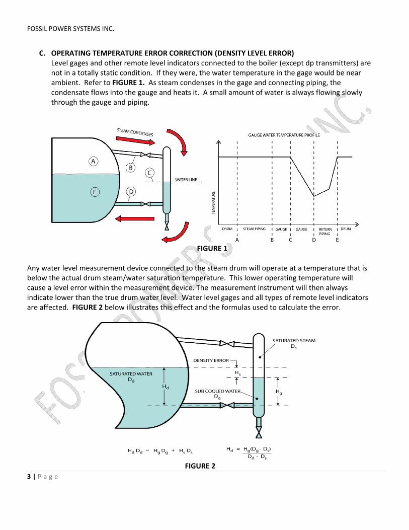
C. OPERATING TEMPERATURE ERROR CORRECTION (DENSITY LEVEL ERROR) Level gages and other remote level indicators connected to the boiler (except dp transmitters) are not in a totally static condition. If they were, the water temperature in the gage would be near ambient. Refer to FIGURE 1. As steam condenses in the gage and connecting piping, the condensate flows into the gauge and heats it. A small amount of water is always flowing slowly through the gauge and piping.
FIGURE 1
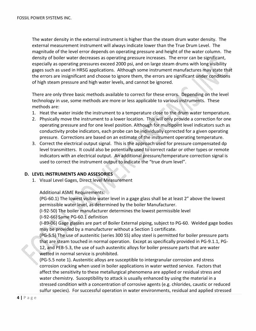
Any water level measurement device connected to the steam drum will operate at a temperature that is below the actual drum steam/water saturation temperature. This lower operating temperature will cause a level error within the measurement device. The measurement instrument will then always indicate lower than the true drum water level. Water level gages and all types of remote level indicators are affected. FIGURE 2 below illustrates this effect and the formulas used to calculate the error.
FIGURE 2
FOSSIL POWER SYSTEMS INC.
4 | P a g e
The water density in the external instrument is higher than the steam drum water density. The external measurement instrument will always indicate lower than the True Drum Level. The magnitude of the level error depends on operating pressure and height of the water column. The density of boiler water decreases as operating pressure increases. The error can be significant, especially as operating pressures exceed 2000 psi, and on large steam drums with long visibility gages such as used in HRSG applications. Although some instrument manufactures may state that the errors are insignificant and choose to ignore them, the errors are significant under conditions of high steam pressure and high water levels, and cannot be ignored. There are only three basic methods available to correct for these errors. Depending on the level technology in use, some methods are more or less applicable to various instruments. These methods are: 1. Heat the water inside the instrument to a temperature close to the drum water temperature. 2. Physically move the instrument to a lower location. This will only provide a correction for one
operating pressure and for one level position. Although for multipoint level indicators such as conductivity probe indicators, each probe can be individually corrected for a given operating pressure. Corrections are based on an estimate of the instrument operating temperature.
3. Correct the electrical output signal. This is the approach used for pressure compensated dp level transmitters. It could also be potentially used to correct radar or other types or remote indicators with an electrical output. An additional pressure/temperature correction signal is used to correct the instrument output to indicate the “true drum level”.
D. LEVEL INSTRUMENTS AND ASSESORIES
1. Visual Level Gages, Direct level Measurement Additional ASME Requirements: (PG‐60.1) The lowest visible water level in a gage glass shall be at least 2” above the lowest permissible water level, as determined by the boiler Manufacturer. (I‐92‐50) The boiler manufacturer determines the lowest permissible level (I‐92‐66) Same PG‐60.1 definition (I‐89‐06) Gage glasses are part of Boiler External piping, subject to PG‐60. Welded gage bodies may be provided by a manufacturer without a Section 1 certificate. (PG‐5.5) The use of austenitic (series 300 SS) alloy steel is permitted for boiler pressure parts that are steam touched in normal operation. Except as specifically provided in PG‐9.1.1, PG‐12, and PEB‐5.3, the use of such austenitic alloys for boiler pressure parts that are water wetted in normal service is prohibited. (PG‐5.5 note 1). Austenitic alloys are susceptible to intergranular corrosion and stress corrosion cracking when used in boiler applications in water wetted service. Factors that affect the sensitivity to these metallurgical phenomena are applied or residual stress and water chemistry. Susceptibility to attack is usually enhanced by using the material in a stressed condition with a concentration of corrosive agents (e.g. chlorides, caustic or reduced sulfur species). For successful operation in water environments, residual and applied stressed
FOSSIL POWER SYSTEMS INC.
5 | P a g e
must be minimized and careful attention must be paid to continuous control of water chemistry. (PG‐12.1) Gage glass body and connector materials shall comply with a Manufacturers standard that defines the pressure‐temperature rating marked on the unit. The materials used may include austenitic stainless steels and nickel‐based alloys. Density Error Considerations: Visual gauges are typically positioned without consideration for density level error. These will indicate correctly at low pressure, with increasing error as pressure increases. If the gauge must be “density corrected” there are several approaches: 1. Heat the water in the gauge with an additional pipe connected to the steam down‐comer (referred
to as steam heating or temperature equalization). 2. Install the gauge in a lower position, calculated for one pressure and one indicated level. 3. Provide a chart at the gauge showing the amount of correction at various operating pressures.
a. Reflex Gages. See FIGURE 3. These gages have grooved glass that applies the principles of
light reflection and transmission to develop a White/Black image, indicating the water level. Maximum operating steam pressure is typically 350 psi. See FIGURE 4 that demonstrates this operating principle.
FIGURE 3
FIGURE 4
Additional ASME Requirements: (PG‐60.1) Gage glass assemblies having multiple sections, whether of tubular or other construction, shall be designed in such a manner that will ensure a minimum of 1” (25 mm)
FOSSIL POWER SYSTEMS INC.
6 | P a g e
overlap of all adjoining sections in which the water level may be visible, except that ported or REFLEX gages that use refraction of light to aid ready determination of the liquid level, may omit the requirement for overlapping sections. (I‐04‐38) Describes same requirements as above.
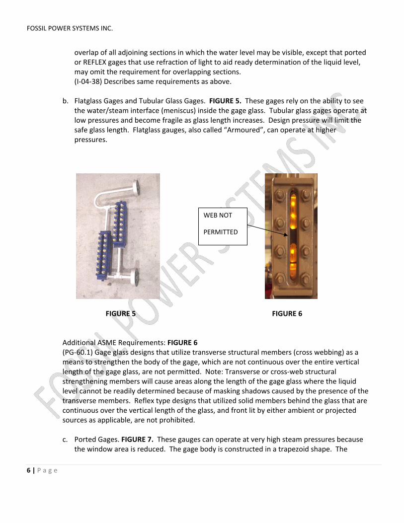
b. Flatglass Gages and Tubular Glass Gages. FIGURE 5. These gages rely on the ability to see
the water/steam interface (meniscus) inside the gage glass. Tubular glass gages operate at low pressures and become fragile as glass length increases. Design pressure will limit the safe glass length. Flatglass gauges, also called “Armoured”, can operate at higher pressures.
FIGURE 5 FIGURE 6
Additional ASME Requirements: FIGURE 6 (PG‐60.1) Gage glass designs that utilize transverse structural members (cross webbing) as a means to strengthen the body of the gage, which are not continuous over the entire vertical length of the gage glass, are not permitted. Note: Transverse or cross‐web structural strengthening members will cause areas along the length of the gage glass where the liquid level cannot be readily determined because of masking shadows caused by the presence of the transverse members. Reflex type designs that utilized solid members behind the glass that are continuous over the vertical length of the glass, and front lit by either ambient or projected sources as applicable, are not prohibited. c. Ported Gages. FIGURE 7. These gauges can operate at very high steam pressures because
the window area is reduced. The gage body is constructed in a trapezoid shape. The
WEB NOT
PERMITTED
FOSSIL POWER SYSTEMS INC.
7 | P a g e
illuminator will project a RED and GREEN light through the ports to provide a RED/GREEN indication of drum water level.
FIGURE 7
Additional ASME Requirements: (PG‐60.1) Ported gages or reflex gages that use refraction of light to aid ready determination of the liquid level, may omit the requirement for overlapping sections. FIGURE 8 illustrates this operating principle and the imaged displayed.
FIGURE 8
FOSSIL POWER SYSTEMS INC.
8 | P a g e
(I‐07‐08) A hand held light source (flashlight) held behind a ported gage does not satisfy the requirement that the gage be equipped to provide obvious visual discrimination between water and vapor in the individual sections. Note: A RED/GREEN illuminator designed for proper display of the level in the bi‐colour gauge MUST be used to satisfy this ASME requirement.
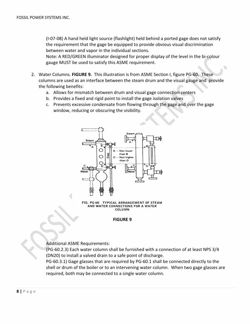
2. Water Columns. FIGURE 9. This illustration is from ASME Section I, figure PG‐60. These
columns are used as an interface between the steam drum and the visual gauge and provide the following benefits:
a. Allows for mismatch between drum and visual gage connection centers b. Provides a fixed and rigid point to install the gage isolation valves c. Prevents excessive condensate from flowing through the gage and over the gage
window, reducing or obscuring the visibility.
FIGURE 9
Additional ASME Requirements: (PG‐60.2.3) Each water column shall be furnished with a connection of at least NPS 3/4 (DN20) to install a valved drain to a safe point of discharge. PG‐60.3.1) Gage glasses that are required by PG‐60.1 shall be connected directly to the shell or drum of the boiler or to an intervening water column. When two gage glasses are required, both may be connected to a single water column.
FOSSIL POWER SYSTEMS INC.
9 | P a g e
(PG‐60.3.2) The lower edge of the steam connection between a water column, gage glass or austenitic stainless steel or nickel‐based alloy water level sensing device in the boiler shall not be below the highest visible water level in the gage glass. There shall be no sag or offset in the piping that will permit the accumulation of water. (PG‐60.3.3) The upper edge of the water connection between a water column, gage glass, or austenitic stainless steel of nickel‐based allow water level sensing device and the boiler shall not be above the lowest visible water level in the gage glass. No part of this pipe connection shall be above the point of connection at the water column. (PG‐60.3.4) Connections from the boiler to the water column shall be at least NPS 1 (DN25)
3. Conductivity Probe Systems. FIGURE 10 These devices measure level using the principle that the conductivity of water and steam are significantly different. The conductivity probe acts like an on/off switch. A low voltage is applied to the probe tip that is insulated from the column body. The return signal is measured by an electronic circuit. Steam appears as an open circuit, while water shorts the probe to ground and appears as a closed circuit. The conductivity probes are located at various locations in a probe column to provide discrete indications of drum water level.
FIGURE 10
FOSSIL POWER SYSTEMS INC.
10 | P a g e
Additional ASME Requirements: (I‐01‐22) Austenitic materials (series 300 SS) cannot be used for level indicators (I‐01‐25) Conductivity probe type level columns cannot use austenitic materials. Density Error Considerations. As discussed earlier, water temperature in the probe column will be lower than the drum water temperature, causing a density level error. Probe locations can be individually corrected to improve the accuracy of the indicated drum level at a specific operating pressure. Probes at high levels receive more correction than probes at low levels. Measurement errors are introduced when operating at pressures other than the normal operating pressure, and in particular when at cold startup conditions.
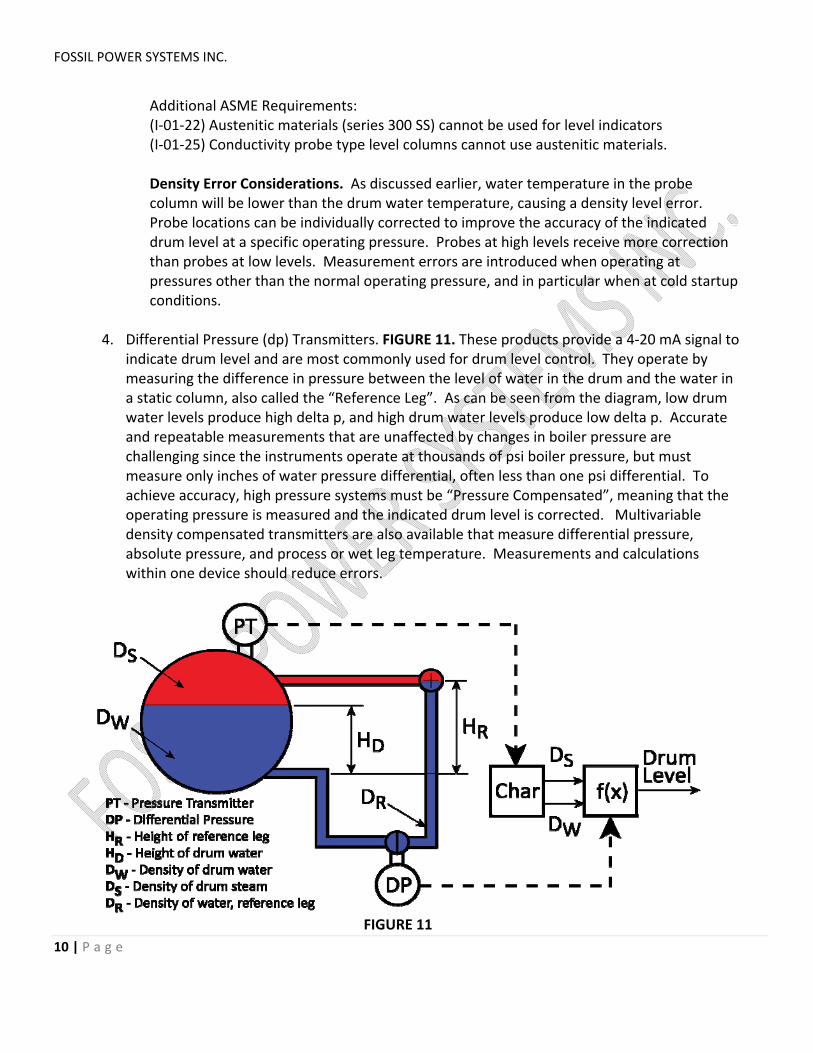
4. Differential Pressure (dp) Transmitters. FIGURE 11. These products provide a 4‐20 mA signal to indicate drum level and are most commonly used for drum level control. They operate by measuring the difference in pressure between the level of water in the drum and the water in a static column, also called the “Reference Leg”. As can be seen from the diagram, low drum water levels produce high delta p, and high drum water levels produce low delta p. Accurate and repeatable measurements that are unaffected by changes in boiler pressure are challenging since the instruments operate at thousands of psi boiler pressure, but must measure only inches of water pressure differential, often less than one psi differential. To achieve accuracy, high pressure systems must be “Pressure Compensated”, meaning that the operating pressure is measured and the indicated drum level is corrected. Multivariable density compensated transmitters are also available that measure differential pressure, absolute pressure, and process or wet leg temperature. Measurements and calculations within one device should reduce errors.
FIGURE 11
FOSSIL POWER SYSTEMS INC.
11 | P a g e
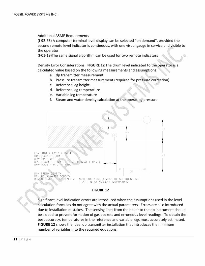
Additional ASME Requirements (I‐92‐63) A computer terminal level display can be selected “on demand”, provided the second remote level indicator is continuous, with one visual gauge in service and visible to the operator. (I‐01‐19)The same signal algorithm can be used for two remote indicators Density Error Considerations: FIGURE 12 The drum level indicated to the operator is a calculated value based on the following measurements and assumptions:
a. dp transmitter measurement b. Pressure transmitter measurement (required for pressure correction) c. Reference leg height d. Reference leg temperature e. Variable leg temperature f. Steam and water density calculation at the operating pressure
LP= H1D1 + H2D2 + H4D4
HP= H3D3 + H4D4DP= HP - LP
DP= (H3D3 + H4D4) - (H1D1 + H2D2 + H4D4)
DP= H3D3 - H1D1 - H2D2
D1= STEAM DENSITY
D2= DRUM WATER DENSITY
D3= REFERENCE LEG DENSITY NOTE: DISTANCE X MUST BE SUFFICIENT SO
THAT T IS AT AMBIENT TEMPRATURE
FIGURE 12
Significant level indication errors are introduced when the assumptions used in the level calculation formulas do not agree with the actual parameters. Errors are also introduced due to installation mistakes. The sensing lines from the boiler to the dp instrument should be sloped to prevent formation of gas pockets and erroneous level readings. To obtain the best accuracy, temperatures in the reference and variable legs must accurately estimated. FIGURE 12 shows the ideal dp transmitter installation that introduces the minimum number of variables into the required equations.
FOSSIL POWER SYSTEMS INC.
12 | P a g e
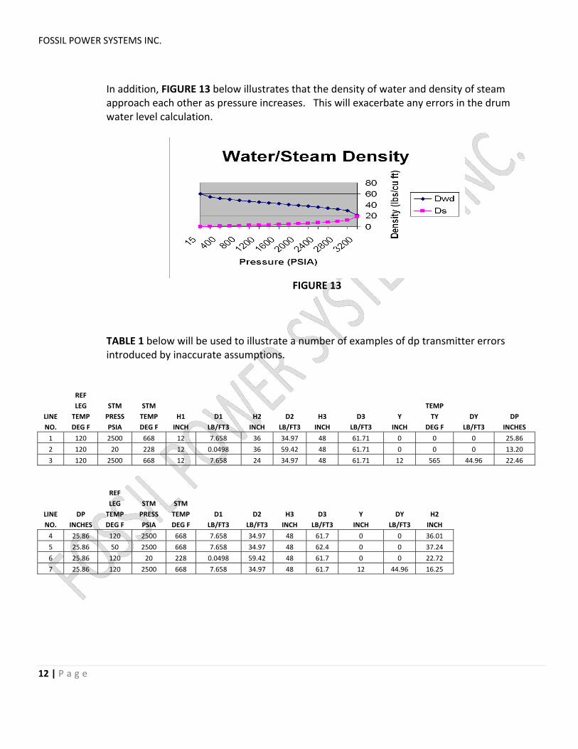
In addition, FIGURE 13 below illustrates that the density of water and density of steam approach each other as pressure increases. This will exacerbate any errors in the drum water level calculation.
FIGURE 13
TABLE 1 below will be used to illustrate a number of examples of dp transmitter errors introduced by inaccurate assumptions.
REF
LEG STM STM TEMP
LINE TEMP PRESS TEMP H1 D1 H2 D2 H3 D3 Y TY DY DP
NO. DEG F PSIA DEG F INCH LB/FT3 INCH LB/FT3 INCH LB/FT3 INCH DEG F LB/FT3 INCHES
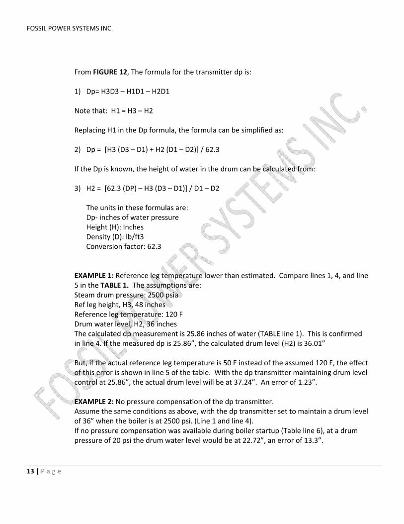
From FIGURE 12, The formula for the transmitter dp is: 1) Dp= H3D3 – H1D1 – H2D1 Note that: H1 = H3 – H2 Replacing H1 in the Dp formula, the formula can be simplified as: 2) Dp = [H3 (D3 – D1) + H2 (D1 – D2)] / 62.3 If the Dp is known, the height of water in the drum can be calculated from: 3) H2 = [62.3 (DP) – H3 (D3 – D1)] / D1 – D2
The units in these formulas are: Dp‐ inches of water pressure Height (H): Inches Density (D): lb/ft3 Conversion factor: 62.3
EXAMPLE 1: Reference leg temperature lower than estimated. Compare lines 1, 4, and line 5 in the TABLE 1. The assumptions are: Steam drum pressure: 2500 psia Ref leg height, H3, 48 inches Reference leg temperature: 120 F Drum water level, H2, 36 inches The calculated dp measurement is 25.86 inches of water (TABLE line 1). This is confirmed in line 4. If the measured dp is 25.86”, the calculated drum level (H2) is 36.01” But, if the actual reference leg temperature is 50 F instead of the assumed 120 F, the effect of this error is shown in line 5 of the table. With the dp transmitter maintaining drum level control at 25.86”, the actual drum level will be at 37.24”. An error of 1.23”. EXAMPLE 2: No pressure compensation of the dp transmitter. Assume the same conditions as above, with the dp transmitter set to maintain a drum level of 36” when the boiler is at 2500 psi. (Line 1 and line 4). If no pressure compensation was available during boiler startup (Table line 6), at a drum pressure of 20 psi the drum water level would be at 22.72”, an error of 13.3”.
FOSSIL POWER SYSTEMS INC.
14 | P a g e
EXAMPLE 3: DP transmitter variable leg connected to the bottom of the drum. The FIGURE 14 below shows this installation method.
FIGURE 14. Variable leg off bottom of drum
LP= H1D1 + H2D2 + H4D4
HP= H3D3 + H4D4
DP= HP - LP
DP= (H3D3 + H4D4) - (H1D1 + H2D2 + H4D4)
DP= H3D3 - H1D1 - H2D2
D1= STEAM DENSITY
D2= DRUM WATER DENSITY
D3= REFERENCE LEG DENSITY
Assuming the same boiler conditions as the first two examples, but “H2” drum level now includes the “Y” component that will be at a lower temperature than the steam drum water saturation temperature. Assume for this installation that “Y” is 12 inches, and this water in this line is sub‐cooled 100 F below the saturated drum water temperature (water at 565 F). The effect of this change is shown in Lines #3 and #7. The drum level from Line #7 will be the total of “Y” and the calculated “H2”, or 28.25”. This is an error of 7.75” from the setpoint (36”).
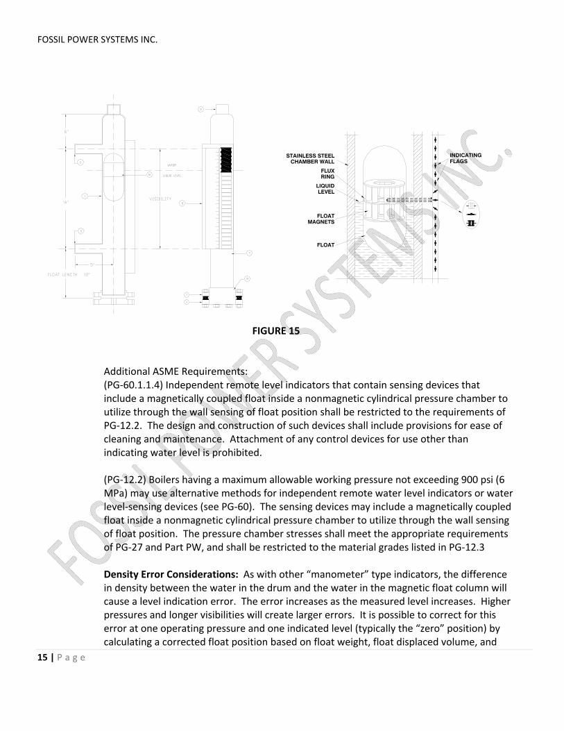
5. Magnetic Float Indicators. FIGURE 15. These devices consist of a stainless steel (or other non‐
magnetic material) pipe chamber and an internal float. The float is also non‐magnetic, but contains a ring of magnets. The magnets within the float operate a magnetic indicator located on the outside of the pressure chamber. The indicator is either a single “follower”, or a series of “flags” that rotate and change colour as the float magnets pass by. The float magnetic ring will collect corrosion particles (iron/steel) from the water and the float must be removed and cleaned periodically, depending on water quality. Floats must become larger as pressure increases due to the reduction in water density.
FOSSIL POWER SYSTEMS INC.
15 | P a g e
INDICATINGFLAGS
STAINLESS STEELCHAMBER WALL
RINGFLUX
LEVELLIQUID
FLOATMAGNETS
FLOAT
FIGURE 15
Additional ASME Requirements: (PG‐60.1.1.4) Independent remote level indicators that contain sensing devices that include a magnetically coupled float inside a nonmagnetic cylindrical pressure chamber to utilize through the wall sensing of float position shall be restricted to the requirements of PG‐12.2. The design and construction of such devices shall include provisions for ease of cleaning and maintenance. Attachment of any control devices for use other than indicating water level is prohibited. (PG‐12.2) Boilers having a maximum allowable working pressure not exceeding 900 psi (6 MPa) may use alternative methods for independent remote water level indicators or water level‐sensing devices (see PG‐60). The sensing devices may include a magnetically coupled float inside a nonmagnetic cylindrical pressure chamber to utilize through the wall sensing of float position. The pressure chamber stresses shall meet the appropriate requirements of PG‐27 and Part PW, and shall be restricted to the material grades listed in PG‐12.3 Density Error Considerations: As with other “manometer” type indicators, the difference in density between the water in the drum and the water in the magnetic float column will cause a level indication error. The error increases as the measured level increases. Higher pressures and longer visibilities will create larger errors. It is possible to correct for this error at one operating pressure and one indicated level (typically the “zero” position) by calculating a corrected float position based on float weight, float displaced volume, and
FOSSIL POWER SYSTEMS INC.
16 | P a g e
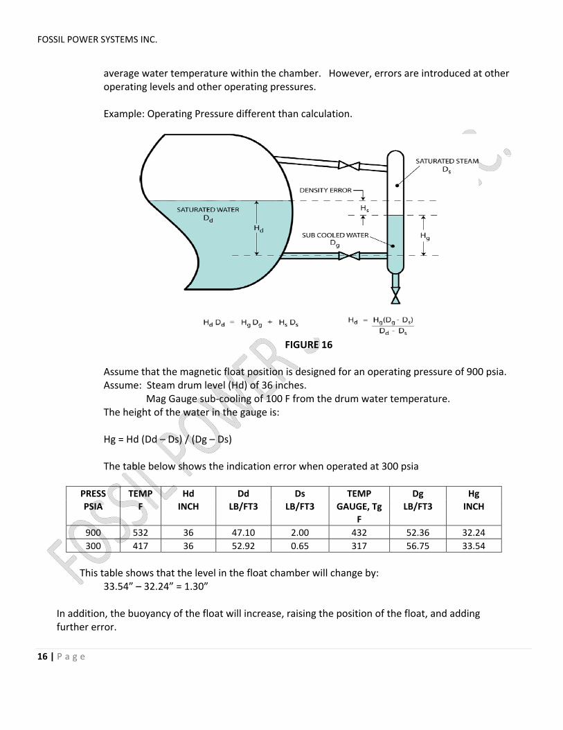
average water temperature within the chamber. However, errors are introduced at other operating levels and other operating pressures. Example: Operating Pressure different than calculation.
FIGURE 16
Assume that the magnetic float position is designed for an operating pressure of 900 psia. Assume: Steam drum level (Hd) of 36 inches. Mag Gauge sub‐cooling of 100 F from the drum water temperature. The height of the water in the gauge is: Hg = Hd (Dd – Ds) / (Dg – Ds) The table below shows the indication error when operated at 300 psia
PRESS TEMP Hd Dd Ds TEMP Dg Hg
PSIA F INCH LB/FT3 LB/FT3 GAUGE, Tg LB/FT3 INCH
F
900 532 36 47.10 2.00 432 52.36 32.24
300 417 36 52.92 0.65 317 56.75 33.54
This table shows that the level in the float chamber will change by:
33.54” – 32.24” = 1.30”
In addition, the buoyancy of the float will increase, raising the position of the float, and adding further error.
FOSSIL POWER SYSTEMS INC.
17 | P a g e
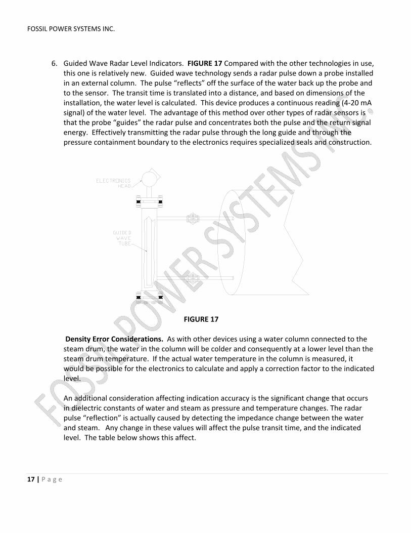
6. Guided Wave Radar Level Indicators. FIGURE 17 Compared with the other technologies in use,
this one is relatively new. Guided wave technology sends a radar pulse down a probe installed in an external column. The pulse “reflects” off the surface of the water back up the probe and to the sensor. The transit time is translated into a distance, and based on dimensions of the installation, the water level is calculated. This device produces a continuous reading (4‐20 mA signal) of the water level. The advantage of this method over other types of radar sensors is that the probe “guides” the radar pulse and concentrates both the pulse and the return signal energy. Effectively transmitting the radar pulse through the long guide and through the pressure containment boundary to the electronics requires specialized seals and construction.
FIGURE 17
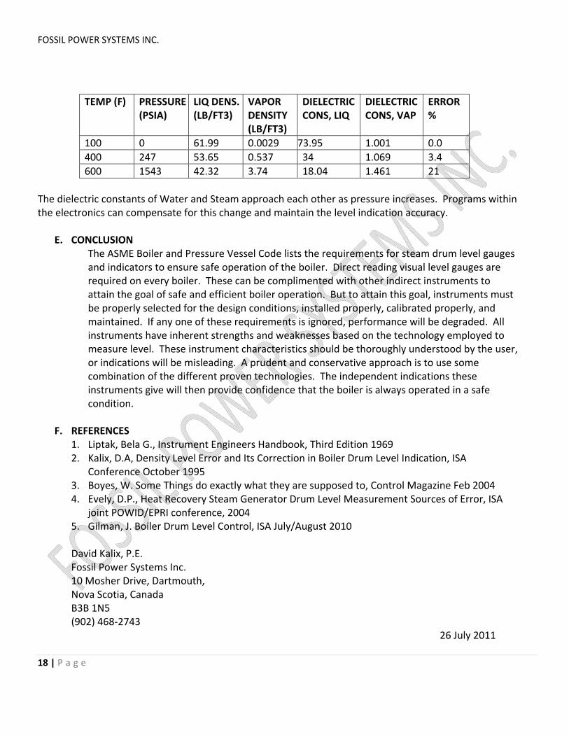
Density Error Considerations. As with other devices using a water column connected to the steam drum, the water in the column will be colder and consequently at a lower level than the steam drum temperature. If the actual water temperature in the column is measured, it would be possible for the electronics to calculate and apply a correction factor to the indicated level. An additional consideration affecting indication accuracy is the significant change that occurs in dielectric constants of water and steam as pressure and temperature changes. The radar pulse “reflection” is actually caused by detecting the impedance change between the water and steam. Any change in these values will affect the pulse transit time, and the indicated level. The table below shows this affect.
FOSSIL POWER SYSTEMS INC.
18 | P a g e
TEMP (F) PRESSURE (PSIA)
LIQ DENS. (LB/FT3)
VAPOR DENSITY (LB/FT3)
DIELECTRIC CONS, LIQ
DIELECTRIC CONS, VAP
ERROR %
100 0 61.99 0.0029 73.95 1.001 0.0
400 247 53.65 0.537 34 1.069 3.4
600 1543 42.32 3.74 18.04 1.461 21
The dielectric constants of Water and Steam approach each other as pressure increases. Programs within the electronics can compensate for this change and maintain the level indication accuracy.
E. CONCLUSION
The ASME Boiler and Pressure Vessel Code lists the requirements for steam drum level gauges and indicators to ensure safe operation of the boiler. Direct reading visual level gauges are required on every boiler. These can be complimented with other indirect instruments to attain the goal of safe and efficient boiler operation. But to attain this goal, instruments must be properly selected for the design conditions, installed properly, calibrated properly, and maintained. If any one of these requirements is ignored, performance will be degraded. All instruments have inherent strengths and weaknesses based on the technology employed to measure level. These instrument characteristics should be thoroughly understood by the user, or indications will be misleading. A prudent and conservative approach is to use some combination of the different proven technologies. The independent indications these instruments give will then provide confidence that the boiler is always operated in a safe condition.
F. REFERENCES 1. Liptak, Bela G., Instrument Engineers Handbook, Third Edition 1969 2. Kalix, D.A, Density Level Error and Its Correction in Boiler Drum Level Indication, ISA
Conference October 1995 3. Boyes, W. Some Things do exactly what they are supposed to, Control Magazine Feb 2004 4. Evely, D.P., Heat Recovery Steam Generator Drum Level Measurement Sources of Error, ISA
joint POWID/EPRI conference, 2004 5. Gilman, J. Boiler Drum Level Control, ISA July/August 2010
David Kalix, P.E. Fossil Power Systems Inc. 10 Mosher Drive, Dartmouth, Nova Scotia, Canada B3B 1N5 (902) 468‐2743