149
© 2005 Compressor Controls Corporation Steam Turbines
| Date post: | 20-Aug-2015 |
| Category: |
Education |
| Upload: | walid-salama |
| View: | 6,064 times |
| Download: | 6 times |

© 2
00
5
Com
pre
ssor
Contr
ols
Corp
ora
tion Steam
TurbinesSteam
Turbines

© 2
00
5
Com
pre
ssor
Contr
ols
Corp
ora
tion
Steam Turbine StandardsSteam Turbine Standards
• API 611 General Purpose Turbines– Typically used for mechanical drives– Process pumps, ID & FD fans, BFP– Spared equipment
• API 612 Special Purpose turbines– Typically used for critical drives– Compressors, axial blowers, BFP– Critical applications
Chap

© 2
00
5
Com
pre
ssor
Contr
ols
Corp
ora
tion
Steam turbine classification by mechanical design
Steam turbine classification by mechanical design
Single valve-single stage

© 2
00
5
Com
pre
ssor
Contr
ols
Corp
ora
tion
Steam turbine classification by mechanical design
Steam turbine classification by mechanical design
Single valve-multi stage

© 2
00
5
Com
pre
ssor
Contr
ols
Corp
ora
tion
612 API Special Purpose Single-Valve Steam Turbine
612 API Special Purpose Single-Valve Steam Turbine

© 2
00
5
Com
pre
ssor
Contr
ols
Corp
ora
tion
API 612 Special Purpose Multi-Valve Steam Turbine
API 612 Special Purpose Multi-Valve Steam Turbine
steam inlet
Multi valve-multi stage

© 2
00
5
Com
pre
ssor
Contr
ols
Corp
ora
tion
Steam turbine classification by steam system
• Steam is expanded to back pressure level
• Remaining energy in steam is used elsewhere
Low pressuresteam header
To other steamusers
Back Pressure Turbine

© 2
00
5
Com
pre
ssor
Contr
ols
Corp
ora
tion
Steam turbine classification by steam system
Back Pressure Turbine

© 2
00
5
Com
pre
ssor
Contr
ols
Corp
ora
tion
• Steam is fully expanded to retrieve maximum amount of energy
To condenser
Steam turbine classification by steam system
Steam turbine classification by steam system
Condensing Turbine

© 2
00
5
Com
pre
ssor
Contr
ols
Corp
ora
tion
Steam turbine classification by steam system
Steam turbine classification by steam system
Condensing Turbine

© 2
00
5
Com
pre
ssor
Contr
ols
Corp
ora
tion
Condensing steam turbineCondensing steam turbine

© 2
00
5
Com
pre
ssor
Contr
ols
Corp
ora
tion
HP LP
Steam turbine classification by mechanical design
Steam turbine classification by mechanical design
Single Extraction Turbine

© 2
00
5
Com
pre
ssor
Contr
ols
Corp
ora
tion
HP LP
Steam turbine classification by mechanical design
Steam turbine classification by mechanical design
Single Admission Turbine

© 2
00
5
Com
pre
ssor
Contr
ols
Corp
ora
tion
Extraction steam turbineExtraction steam turbine

© 2
00
5
Com
pre
ssor
Contr
ols
Corp
ora
tion
V1 V2 V3
HP MP LP
Steam turbine classification by mechanical design
Steam turbine classification by mechanical design
Double Extraction Turbine

© 2
00
5
Com
pre
ssor
Contr
ols
Corp
ora
tion
Steam turbine classification by mechanical design
Steam turbine classification by mechanical design
Double Extraction Turbine

© 2
00
5
Com
pre
ssor
Contr
ols
Corp
ora
tion Evolution
of TurbineControls
Evolutionof TurbineControls
Chap

© 2
00
5
Com
pre
ssor
Contr
ols
Corp
ora
tion
Evolution of Turbine ControlsEvolution of Turbine Controls
• Mechanical Governors
• Hydraulic Mechanical Governors
• Analog Control System
• Digital Control Systems– Simplex Architecture– Duplex Architecture– Triplex Architecture
Chap

© 2
00
5
Com
pre
ssor
Contr
ols
Corp
ora
tion
Mechanical Governor

© 2
00
5
Com
pre
ssor
Contr
ols
Corp
ora
tion
Hydraulic/Mechanical GovernorsHydraulic/Mechanical Governors

© 2
00
5
Com
pre
ssor
Contr
ols
Corp
ora
tion
Hydraulic/Mechanical Governor Hydraulic/Mechanical Governor

© 2
00
5
Com
pre
ssor
Contr
ols
Corp
ora
tion
Hydraulic/Mechanical GovernorsHydraulic/Mechanical Governors

© 2
00
5
Com
pre
ssor
Contr
ols
Corp
ora
tion Hydraulic/Mechanical Governor Limitations
Hydraulic/Mechanical Governor Limitations
• Expensive overhauls
• Mechanical wear
• Limited operator interface
• Oil considerations

© 2
00
5
Com
pre
ssor
Contr
ols
Corp
ora
tion
Analog Governor Analog Governor

© 2
00
5
Com
pre
ssor
Contr
ols
Corp
ora
tion
Analog Control Systems Advantages and Limitations
Analog Control Systems Advantages and Limitations
– Allowed standardization of governor systems
– Reduced the mechanical linkages
– Reduced maintenance costs
– More control capability
– Improved performance
– Better interface to process
Advantages

© 2
00
5
Com
pre
ssor
Contr
ols
Corp
ora
tion
Analog Control Systems Advantages and Limitations
Analog Control Systems Advantages and Limitations
– Frequent and time consuming calibration
– Difficult to reconfigure
– Lack of diagnostics
– Lack of operator interface
Limitations

© 2
00
5
Com
pre
ssor
Contr
ols
Corp
ora
tion
• API 612 Standard Fourth Edition, recognizes Digital Speed Governors as the standard speed control device.
Digital Control SystemsDigital Control Systems

© 2
00
5
Com
pre
ssor
Contr
ols
Corp
ora
tion
Digital Control SystemsDigital Control Systems
• Revolutionized the control industry
• Perform all of the sequencer, logic, and control functions
• Allow advanced control algorithms
• No calibration required
• Diagnostics
• Operator interfaces

© 2
00
5
Com
pre
ssor
Contr
ols
Corp
ora
tion
Why Digital Electronic Governors?Why Digital Electronic Governors?
• Safety– Controlled startup sequence– Backup overspeed – Operator information– Interface with ESD– Overspeed test– Overcomes valve sticking
• Information– Local displays– Communication with DCS
• Functional Obsolescence
– Mechanical governors no longer suitable even in fixed speed applications
– Improved control algorithms– Process interface– Improved efficiency

© 2
00
5
Com
pre
ssor
Contr
ols
Corp
ora
tion
Digital Control Systems Advantages
Digital Control Systems Advantages
• Ease of configuration increases flexibility
• Reduced maintenance
• Selectable fault tolerance
• Multiple operator interfaces
• Improved diagnostics and fault detection
• DCS compatibility
• Advance control algorithms
• Improved machinery protection

© 2
00
5
Com
pre
ssor
Contr
ols
Corp
ora
tion
Challenges and opportunities in steam turbine control
Challenges and opportunities in steam turbine control
• Overspeed is the danger– Avoidance by the control system– Detection and trip by separate system
• Electronic controls are superior to hydro-mechanical controls– More accurate and repeatable– Can be integrated with other controllers– Better operator interfaces– Can be redundant for control, voting for trip

© 2
00
5
Com
pre
ssor
Contr
ols
Corp
ora
tion Speed
MeasurementSpeed
Measurement

© 2
00
5
Com
pre
ssor
Contr
ols
Corp
ora
tion
• In order to optimize the control loop all four blocks must be optimized
• Therefore accurate and reliable speed measurement is required
The importance of speed measurement
The importance of speed measurement
TurbineTurbine
MeasurementMeasurement
ControlControl
ControlElementControlElement

© 2
00
5
Com
pre
ssor
Contr
ols
Corp
ora
tion
• Magnetic pickups are non-contact sensors
- Passive sensors• Use a magnet and moving gear teeth to
generate a pulse that is proportional to speed• Have a minimum operating speed• A variable amplitude and frequency output
- Active sensors• Require a power source due to amplifier stage
built in pickups• Operate at very low frequencies due to
amplifier• A fixed amplitude and variable frequency
output
Magnetic pickupsMagnetic pickups

© 2
00
5
Com
pre
ssor
Contr
ols
Corp
ora
tion
Magnetic pickupsMagnetic pickups

© 2
00
5
Com
pre
ssor
Contr
ols
Corp
ora
tion
• As the magnetic material of the teeth gear rotates by the MPU it generates a pulse in the coil of the MPU
Voltage
MagneticPickup
How do MPU’s work?How do MPU’s work?

© 2
00
5
Com
pre
ssor
Contr
ols
Corp
ora
tion
Voltage
MagneticPickup
Voltage
MagneticPickup
TimeTime
ExampleN=1000 RPM
ExampleN=2000 RPM
Note: Represents passive MPU
Frequency is proportional to speed
Frequency is proportional to speed

© 2
00
5
Com
pre
ssor
Contr
ols
Corp
ora
tion
Existing Governor MountingPad
Section View of Turbine Front Standard
MPU and speed sensinggear retrofit
MPU and speed sensinggear retrofit

© 2
00
5
Com
pre
ssor
Contr
ols
Corp
ora
tion
Speed Sensing Gear InstallationSpeed Sensing Gear Installation

© 2
00
5
Com
pre
ssor
Contr
ols
Corp
ora
tion
Too Fast
Typical Turbine Speed ProfileTypical Turbine Speed Profile
Ste
am T
urb
ine
Sp
eed
Control ThresholdControl ThresholdMPUs Unreliable
Minimum ControlMinimum Control
Idle Speed - 1Idle Speed - 1
Critical Range - 1Critical Range - 1 Excessive Vibration
Critical Range - 2Critical Range - 2 Excessive Vibration
Idle Speed - 2Idle Speed - 2
Minimum GovernorMinimum Governor
Maximum GovernorMaximum Governor
Overspeed TripOverspeed Trip
Maximum ControlMaximum Control
No
rmal
Op
erat
ing
R
ang
e
No
rmal
Op
erat
ing
R
ang
e
Co
ntr
ol
Ra
ng
e
Co
ntr
ol
Ra
ng
e
Va
lid
Sp
ee
dR
an
ge
Va
lid
Sp
ee
dR
an
ge
Rated SpeedRated Speed 100%
105%
115%

© 2
00
5
Com
pre
ssor
Contr
ols
Corp
ora
tion Overspeed
ProtectionOverspeed
Protection

© 2
00
5
Com
pre
ssor
Contr
ols
Corp
ora
tion
Traditional systems lack speed of response
Traditional systems lack speed of response
• Steam turbines can accelerate extremely fast during upsets , such as :- – Surge on the compressor– Breaker trip on the generator– Fast power reduction on the local grid
• Traditional speed control is too slow to catch these type of disturbancesResults:– Machine and process shutdown due to over
speed– Machine damage

© 2
00
5
Com
pre
ssor
Contr
ols
Corp
ora
tion
TN WR
hpc rotor
rated
rated,
.
619
10
2 2
6Rotor time constant:
where:
– NR Rated speed (RPM)
– WR2 Rotor inertia (lbs-ft2)
– hp Rated horsepowerTc,rotor is time it would take rotor speed
to double if unit were operating at:
• Rated horsepower and rated speed• Load was lost instantaneously • The rotor continued to change speed at its
initial rate
Steam turbine rotor dynamicsSteam turbine rotor dynamics

© 2
00
5
Com
pre
ssor
Contr
ols
Corp
ora
tion
• Turbine speed will be 27,000 rpm after 2.25 seconds
• Overspeed trip settings (115% rated) will be reached in 337 ms
• Overspeed trip system needs to react in 225 ms to prevent speed from exceeding 125% level
TN WR
hpc rotor
rated
rated,
.
619
10
2 2
6
Tc rotor,. ,
,
619 13500 50
10 2 500
2 2
6
Recycle compressor data:• NR Rated speed (RPM)
13,500• WR2 Rotor inertia (lbs-ft2) 50• hp Rated horsepower
2,500 Tc rotor, .2 25seconds
Example of steam turbine driven recycle compressor
Steam turbine rotor dynamicsSteam turbine rotor dynamics

© 2
00
5
Com
pre
ssor
Contr
ols
Corp
ora
tion
Overspeed ProtectionOverspeed Protection
• Governor is the first line of defense for preventing over speed
• Governor electronic trip acts as a backup to the primary overspeed trip device
• Primary overspeed trip system– Electronic over speed trip system– Mechanical over speed trip system

© 2
00
5
Com
pre
ssor
Contr
ols
Corp
ora
tion SE
3x
1SIC
LoadSteam turbine
V1
The overspeed avoidance algorithm
The overspeed avoidance algorithm

© 2
00
5
Com
pre
ssor
Contr
ols
Corp
ora
tion
Overspeed Avoidance AlgorithmS
team
D
eman
dS
PE
ED
Time
Time
Electronic Overspeed Trip Limit
Overspeed Avoidance - Open Loop
Maximum Governor Speed
Dead time
Close FCV
Speed Set Point

© 2
00
5
Com
pre
ssor
Contr
ols
Corp
ora
tion
Open loop control lacks the accuracy of closed loop control
Open loop control lacks the accuracy of closed loop control
• Typically the step is too small or too big
• The rate of change of speed (dN/dt) is an excellent predictor for the size of the load drop
• The actual step size changes with the rate of change of speed

© 2
00
5
Com
pre
ssor
Contr
ols
Corp
ora
tion
Step = Constant .dNdt
• System adapts to the size of the disturbance• Bigger disturbances provoke faster closing of
the valve
Time
RPM
V1
Time
RPM
V1
OverspeedAvoidance
Medium disturbance Large disturbance
Improving the effectiveness of the overspeed avoidance algorithm
Improving the effectiveness of the overspeed avoidance algorithm

© 2
00
5
Com
pre
ssor
Contr
ols
Corp
ora
tion
Benefits
• Overspeed can be avoided for virtually any disturbance
• Increase machine life
• Process is kept on line
Benefits of overspeed avoidance algorithm
Benefits of overspeed avoidance algorithm

© 2
00
5
Com
pre
ssor
Contr
ols
Corp
ora
tion
• Turbomachinery losses among the highest paid by insurers
• Overspeed represents one the most catastrophic accidents– endangers personnel
– damages the turbomachinery train
– can cause damage to other plant equipment
– Can result in costly interruptions of process
• Mechanical overspeed trip systems are non–redundant, require overspeed proof test, imprecise and unreliable
Why Electronic Overspeed Protection?Why Electronic Overspeed Protection?

© 2
00
5
Com
pre
ssor
Contr
ols
Corp
ora
tion
Overspeed Protection StandardsOverspeed Protection Standards
• API Standard 612Petroleum, Petrochemical, and Natural Gas Industries – Steam Turbine – Special Purpose Applications - 5th Edition
(Published Apr 2003)
• API Standard 670Machinery Protection Systems 4th Edition
(Published Dec 2000)
• ISO Standard 10437Petroleum, Petrochemical, and Natural Gas Industries – Steam Turbine – Special Purpose Applications
(Published 2003)

© 2
00
5
Com
pre
ssor
Contr
ols
Corp
ora
tion
API/ISO Governing and ProtectionSpeed Requirements
API/ISO Governing and ProtectionSpeed Requirements
• Maximum Temporary Overshoot Speed– 125%
• Overspeed Trip Speed – 116%
• Max Allowable Speed Rise per NEMA D– 112%
• Maximum Continuous Operating Speed– 105%
• Rated Operating Speed– 100%

© 2
00
5
Com
pre
ssor
Contr
ols
Corp
ora
tion
API /ISO StandardAPI /ISO Standard
• API/ISO Standards recognizes electronic over speed trip systems as the standard over speed protection device.
• Electronic Over Speed Detection utilizing 2-out-of-3 voting is specified.
• The electronic overspeed detection system shall be dedicated to the over speed detection function only.
• It shall be separate from and independent of all other control and protective systems

© 2
00
5
Com
pre
ssor
Contr
ols
Corp
ora
tion
API /ISO StandardAPI /ISO Standard
• Response time for detection system < 40 mSec
• An overspeed condition sensed by one module shall initiate an alarm
• An overspeed condition sensed by two modules shall initiate a shutdown
• Failure of one speed sensor, power supply, or logic device shall initiate an alarm
• Failure of two speed sensors or logic devices in two circuits shall initiate a shutdown

© 2
00
5
Com
pre
ssor
Contr
ols
Corp
ora
tion
API /ISO StandardAPI /ISO Standard
• All settings shall be field configurable with controlled access
• Dedicated speed sensors are required
• Peak speed capture is required with controlled access to reset
• Overspeed trip tests require controlled access• System shall be provided with redundant power
supplies– Each power supply shall be independently capable of
supply power for the entire system
• Operating Temperature range –20C to +65C

© 2
00
5
Com
pre
ssor
Contr
ols
Corp
ora
tion
API/ISO Installation Diagram API/ISO Installation Diagram

© 2
00
5
Com
pre
ssor
Contr
ols
Corp
ora
tion
Guardian® Overspeed Prevention System
Guardian® Overspeed Prevention System
Protecting Your
Turbomachinery Train
Against Overspeed
Damage
Protecting Your
Turbomachinery Train
Against Overspeed
Damage

© 2
00
5
Com
pre
ssor
Contr
ols
Corp
ora
tion
• API 670 compliant
• 2oo3 voting for maximum reliability and availability
• Multiple levels of password protection
• Operation and maintenance from front panel key pad
• Completely stand-alone and independent system
• Back-lit LCD displays provide clear operator information
• Tachometer, setpoints and Alarms displayed
• Remote inputs for Start, Reset, and Emergency Shutdown
• ATEX, and CSA Certification for Hazardous Areas
• Modbus RTU protocol
• Peak Speed Retention
• Online Overspeed Test Function
Guardian® Overspeed Prevention System Features
Guardian® Overspeed Prevention System Features

© 2
00
5
Com
pre
ssor
Contr
ols
Corp
ora
tion
• Economic Considerations - Mechanical trip tests require extended downtime due to
delayed startups resulting in production losses - Elimination of nuisance trips associated with mechanical trip
systems increases production
• Safety Considerations - Unreliable mechanical trip systems increase safety hazards
- Uncoupled overspeed trip tests increases safety hazards
- Precise online testing ensures system performance
• Mechanical Considerations - Mechanical linkages are eliminated- Reduction of preventative maintenance requirements- Elimination of costly overhauls
Guardian® Overspeed Prevention System Justification
Guardian® Overspeed Prevention System Justification

© 2
00
5
Com
pre
ssor
Contr
ols
Corp
ora
tion
Advanced Control
Algorithms
Advanced Control
Algorithms

© 2
00
5
Com
pre
ssor
Contr
ols
Corp
ora
tion
ProcessProcess
Process change causeschange in control variable
MeasurementMeasurement
Change in controlvariable is measured
ControlControl
Controller comparesPV and SP and determines
action (output)
ControlElementControlElement
Control element influences process to get control variableback to desired level
Basic elements of a Control LoopBasic elements of a Control Loop

© 2
00
5
Com
pre
ssor
Contr
ols
Corp
ora
tion
Turbine load changes andcauses speed to change
Magnetic Pickup
measuresspeed change
Load
AUX Antisurge Controller
ALT OUT
RPM
COMPRESSORCONTROLSCORPORATION
MAN
AUTO
RESETSAFETY
ON
DISPLAYSURGECOUNT
DISPLAYLIMIT
MENU SCROLL
AutoManual
RTLimitTracking
Fallback
Fault
0.4Status RUN
SO
TranFail
ComErr
32500.40.4
SIC-1
SP
OUTPV
Speed controller comparesPV and SP and determines action
V1
Output of SIC changesposition of control elementto move speed back to SP
Basic Speed Control loop elements
Basic Speed Control loop elements

© 2
00
5
Com
pre
ssor
Contr
ols
Corp
ora
tion
Time
RPMV1
Bearing Lube Oil Shaft
High friction
Low friction
SE3x
1SIC
LoadSteam turbine
V1
Break away can be extremely fast
Break away can be extremely fast

© 2
00
5
Com
pre
ssor
Contr
ols
Corp
ora
tion
Time
RPMV1
RPM-SP
Benefits• Reduced overshoot during breakaway of
turbine• Less mechanical stress on cold machine• Reliable and repeatable start up
Break away control prevents machine damage
Break away control prevents machine damage
SE3x
1SIC
LoadSteam turbine
V1
Break Away

© 2
00
5
Com
pre
ssor
Contr
ols
Corp
ora
tion
Time
RPM OEM warm-up diagram
Idle 1
Warm-uptime 1
Idle 2
Warm-uptime 2
• OEM provides warm-up schedules for steam turbine
• Machine needs to be kept for certain period on given speed
• Typically there are 1 or 2 warm-up or idle speeds
• After warm-up the machine can be loaded
To minimumgovernor
Warm-up schedules for steam turbinesWarm-up schedules for steam turbines

© 2
00
5
Com
pre
ssor
Contr
ols
Corp
ora
tion
• Speed controller automatically ramps turbine to Idle 1 and Idle 2
• Machine accelerates or decelerates at configurable ramp rates
• Ramps can be aborted and resumed at any time• Auto Sequencing based on Hot and Cold Ramp
Profiles
Time
RPM OEM warm-up diagram
Idle 1
Warm-uptime 1
Idle 2
Warm-uptime 2
To minimumgovernor
Warm-up schedules for steam turbinesWarm-up schedules for steam turbines

© 2
00
5
Com
pre
ssor
Contr
ols
Corp
ora
tion
Benefits:• Due to closed loop control, machine is
kept on warm-up speed even when steam conditions change
• Operator can focus on other parts of the plant during startup
• Reliable and repeatable startup -- operator independent
• Allows for remote starting from DCS
Benefits of automatic warm-upBenefits of automatic warm-up

© 2
00
5
Com
pre
ssor
Contr
ols
Corp
ora
tion
• Critical speed is a speed at which the turbomachinery train vibrates at a harmonic or resonant frequency
• Most turbomachinery trains have at least one and often multiple critical speeds
• Operating the turbomachinery train too close to one of the critical speeds will result in severe damage
• Critical speeds are typically below minimum governor
• Critical speeds need to be avoided by the control system
Critical speedsCritical speeds

© 2
00
5
Com
pre
ssor
Contr
ols
Corp
ora
tion
Time
RPM-SPRPM
V1
Ncritical,low
Ncritical,high
Critical Speed RangeCritical Speed Range
Critical speed avoidanceCritical speed avoidance
• Critical speed range low and high values are configured
• RPM-SP cannot be set in this range
• As soon as RPM-SP goes above Ncritical,low the controller ramps RPM-SP to Ncritical.high based on configurable ramp rate
• Machine accelerates to other side of critical speed range due to opening of V1 steam valve
• Different ramp rates can be configured

© 2
00
5
Com
pre
ssor
Contr
ols
Corp
ora
tion
Ncritical,low
Ncritical,high
Critical Speed RangeCritical Speed Range
Time
RPM-SPRPM
Time
0%
100%
V1
t1
Avoiding critical speed damage during lack of steam
Avoiding critical speed damage during lack of steam
• With V1 100% open machine does not reach Ncritical,high within predetermined time t1 due to lack of steam pressure and/or flow
• RPM-SP is ramped thru Ncritical,high
• Controller opens V1 to accelerate turbine to Ncritical,high
• Controller ramps down RPM-SP to Ncritical,low
• Machine decelerates to Ncritical,low
• Machine damage is avoided
© 2
00
5
Com
pre
ssor
Contr
ols
Corp
ora
tion
Time
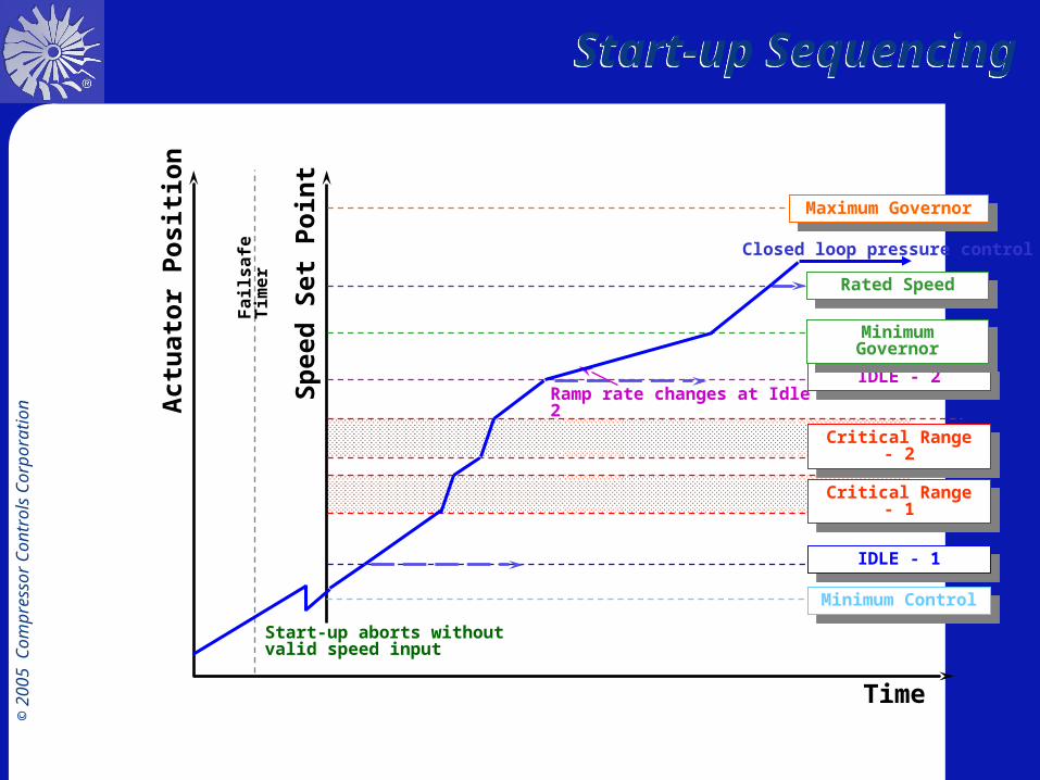
Start-up SequencingStart-up Sequencing
Sp
eed
Set
Po
int
Act
uat
or
Po
siti
on
Start-up aborts without valid speed input
Local SP
Minimum ControlMinimum Control
Fa
ils
afe
Tim
er
Ramp rate changes at Idle 2
IDLE - 1IDLE - 1
Critical Range - 1Critical Range - 1
Critical Range - 2Critical Range - 2
IDLE - 2IDLE - 2
Minimum GovernorMinimum Governor
Rated SpeedRated Speed
Maximum GovernorMaximum Governor
Closed loop pressure control

© 2
00
5
Com
pre
ssor
Contr
ols
Corp
ora
tion • The steam turbine is driving a load
• The load consumes a certain power
• The steam turbine has to provide this power
• At constant speed the power consumed by the load is equal to the power delivered by the steam turbine
• Traditionally load matching is achieved by speed control
• Constant speed means power equilibrium
• The true objective of the steam turbine is to provide power and NOT speed
Controlling power vs. speedControlling power vs. speed
SE3x
1SIC
LoadSteam turbine
V1

© 2
00
5
Com
pre
ssor
Contr
ols
Corp
ora
tion
• Power is a function of (speed)3
• Power is indirectly controlled by keeping the speed constant for a specific load
• Traditional systems linearize the relationship between speed and power between minimum and maximum governor
Power = f(N3)Power = f(N3)
SpeedSpeed
PowerPower
MinimumGovernor
MinimumGovernor
MaximumGovernor
MaximumGovernor

© 2
00
5
Com
pre
ssor
Contr
ols
Corp
ora
tion
• Loop gain is composed of gain of individual blocks:
• Turbine
TurbineTurbine
• Measurement
• Controller
ControlControl
• Control element
ControlElementControlElement
• For given gains of other blocks there is an optimum tuning for speed controller (gain)
• Relationship speed versus power is non-linear
• Optimum gain is for a given speed and not for power
• Power is true controlled -- indirect -- variable
MeasurementMeasurement
The gain is variable over the speed rangeThe gain is variable
over the speed range

© 2
00
5
Com
pre
ssor
Contr
ols
Corp
ora
tion
SpeedSpeed
PowerPower
• Traditional governors can operate adequately in a linearized range -- typically minimum to maximum governor
Gain changes as a function of speed
Gain changes as a function of speed

© 2
00
5
Com
pre
ssor
Contr
ols
Corp
ora
tion
• CCC speed controller employs variable gain
• Allows linearization of the gain for power over the complete speed range
Variable gainin CCC speed controller
Variable gainin CCC speed controller
SpeedSpeed
PowerPower Gain characterizationfunction
Gain characterizationfunction
Linear power gainfor completespeed range
Linear power gainfor completespeed range

© 2
00
5
Com
pre
ssor
Contr
ols
Corp
ora
tion
Benefits of variable gainBenefits of variable gain
Benefits
• Allows fastest tuning for all speeds
• More accurate speed control
• Allows operation at low speeds as well as higher speeds
• Good control at low speeds is required to allow for automatic startup

© 2
00
5
Com
pre
ssor
Contr
ols
Corp
ora
tion
ActuatorsActuators

© 2
00
5
Com
pre
ssor
Contr
ols
Corp
ora
tion
Pneumatic ActuatorPneumatic Actuator

© 2
00
5
Com
pre
ssor
Contr
ols
Corp
ora
tion
• Replace governor with pneumatic actuator
Pneumatic retrofit of typical hydraulic mechanical governor
Pneumatic retrofit of typical hydraulic mechanical governor
Main actuatorMain actuator
Pilot ValvePilot Valve
Typical Flyweightgovernor
Typical Flyweightgovernor
I/P4-20mA output signalfrom digital governor

© 2
00
5
Com
pre
ssor
Contr
ols
Corp
ora
tion
Pneumatic Actuator ona Hydraulic Servo
Pneumatic Actuator ona Hydraulic Servo

© 2
00
5
Com
pre
ssor
Contr
ols
Corp
ora
tion
Pneumatic Actuator ona Hydraulic Servo
Pneumatic Actuator ona Hydraulic Servo

© 2
00
5
Com
pre
ssor
Contr
ols
Corp
ora
tion
Benefits• Simple design
• Has required work force and speed for most applications
• Easily maintained
• Good mounting possibilities
• Good availability
• Cost effective
Benefits of Pneumatic ActuatorsBenefits of Pneumatic Actuators

© 2
00
5
Com
pre
ssor
Contr
ols
Corp
ora
tion
Low pressure linear actuatorLow pressure linear actuator

© 2
00
5
Com
pre
ssor
Contr
ols
Corp
ora
tion
• Replace governor with low pressure hydraulic actuator
Main actuatorMain actuator
Pilot ValvePilot Valve
Typical Flyweightgovernor
Typical Flyweightgovernor
Low pressure hydraulic retrofit of typical hydraulic mechanical governor
Low pressure hydraulic retrofit of typical hydraulic mechanical governor
1ZT
1ZIC
1SIC

© 2
00
5
Com
pre
ssor
Contr
ols
Corp
ora
tion
Install fast low pressure hydraulic actuator with digital position control
Install fast low pressure hydraulic actuator with digital position control
• Low Pressure Servo Actuator• Replacement for existing servo• Pressure = 100 psi• Stroke = 5.5 in• Piston Diameter = 6 in

© 2
00
5
Com
pre
ssor
Contr
ols
Corp
ora
tion
Benefits• Low pressure servo actuators replace the existing
actuator, pilot valve, and linkage
• Use the existing oil supply
• Use either internal mechanical, hydraulic, or LVDT feedback
• Use an electronic actuator for controlling the position
Benefits of low pressure hydraulic actuators
Benefits of low pressure hydraulic actuators

© 2
00
5
Com
pre
ssor
Contr
ols
Corp
ora
tion
I/H ConverterI/H Converter
Designed for precise valve position control
Explosion proof design
for CENELEC European
requirements.Standard design for non-explosion proof applications.

© 2
00
5
Com
pre
ssor
Contr
ols
Corp
ora
tion
Low pressure I/H retrofitLow pressure I/H retrofit
• Replace governor with I/H converter
Pilot ValvePilot Valve
BellowsBellows
SpringSpring
Supply
Drain
Supply
Drain
Variablecontrol oil
Main actuatorMain actuator

© 2
00
5
Com
pre
ssor
Contr
ols
Corp
ora
tion
Magnetic force feedback
2-Point controller Amplifier
DC control magnet
I/H Converter Application #1I/H Converter Application #1

© 2
00
5
Com
pre
ssor
Contr
ols
Corp
ora
tion
I/H Converter Application #2I/H Converter Application #2

© 2
00
5
Com
pre
ssor
Contr
ols
Corp
ora
tion
I/H Converter Application #3I/H Converter Application #3

© 2
00
5
Com
pre
ssor
Contr
ols
Corp
ora
tion
I/H Converter InstallationI/H Converter Installation

© 2
00
5
Com
pre
ssor
Contr
ols
Corp
ora
tion
Benefits of I/H installationBenefits of I/H installation
Benefits• Readily available• Minimize impact on existing
installation• Redundancy in all electronics
when redundant I/H converters are used
Notes:• Clean control oil is absolute must• Secondary duplex filter is required

© 2
00
5
Com
pre
ssor
Contr
ols
Corp
ora
tion
Hydraulic to I/H Transducer RetrofitHydraulic to I/H Transducer Retrofit

© 2
00
5
Com
pre
ssor
Contr
ols
Corp
ora
tion
Hydraulic Governor Retrofit with I/H Transducer
Hydraulic Governor Retrofit with I/H Transducer

© 2
00
5
Com
pre
ssor
Contr
ols
Corp
ora
tion
• Replace governor with High pressure hydraulic actuator
Main actuatorMain actuator
Pilot ValvePilot Valve
Typical Flyweightgovernor
Typical Flyweightgovernor
High pressure hydraulic retrofit of typical hydraulic mechanical governor
High pressure hydraulic retrofit of typical hydraulic mechanical governor
1ZT
1ZIC
1SIC
Main actuatorMain actuator
• High pressure servo actuator replace the existing actuator, pilot valve, and linkage– High pressure oil supply
• (1500 to 2000 psi or 100 to 130 bar)
– LVDT or LDT position feedback
– Fast response servo-valve to control oil flow
– Hydraulic cylinder for work force
– Digital valve positioning loop

© 2
00
5
Com
pre
ssor
Contr
ols
Corp
ora
tion
High Pressure Servo ActuatorHigh Pressure Servo Actuator

© 2
00
5
Com
pre
ssor
Contr
ols
Corp
ora
tion
Benefits• Fast stroke and response time• High accuracy of actuator position• Allows fault tolerance • Compact design • Readily available
Benefits of High Pressure Servo Actuators
Benefits of High Pressure Servo Actuators

© 2
00
5
Com
pre
ssor
Contr
ols
Corp
ora
tion
• Position control is extremely fast PID loop (1 ms loop time)
• Position (PV) is measured by LVDT
• SetPoint (SP) comes from speed controller
• Position controller ZIC manipulates coil in servo valve
• Servo valve moves main actuator
Digital position controlDigital position control
1ZT
1ZICPV
1SIC
SP
Main actuatorMain actuator
LVDT PositionTransducer
LVDT PositionTransducer
Servo ValveServo Valve
Position Controller ZICPosition Controller ZIC

© 2
00
5
Com
pre
ssor
Contr
ols
Corp
ora
tion
Benefits
• Extremely fast and accurate position control of main actuator
• Improves quality of total speed control loop
• Eliminates need of calibration of analog systems
• Allows redundancy of all electronics (including final driver)
• Flexibility of having redundant coils and LVDT
Benefits of digital position control
Benefits of digital position control

© 2
00
5
Com
pre
ssor
Contr
ols
Corp
ora
tion
Response from a Conventional Systemon Breaker Disconnect while generating 15 MWResponse from a Conventional System
on Breaker Disconnect while generating 15 MW
© 2
00
5
Com
pre
ssor
Contr
ols
Corp
ora
tion
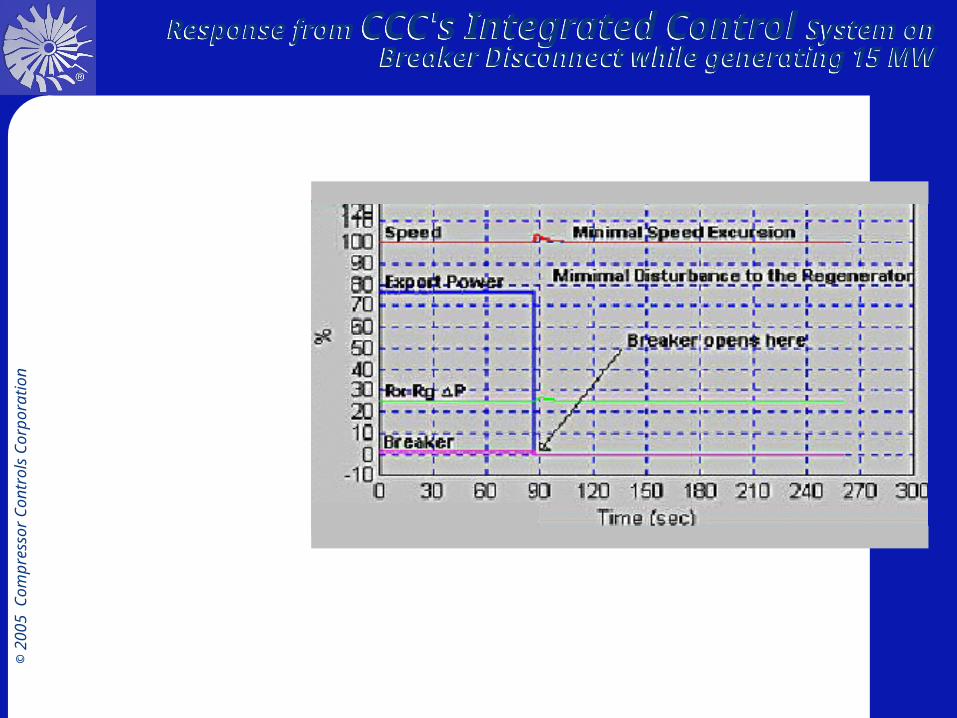
Response from CCC's Integrated Control System on Breaker Disconnect while generating 15 MW
Response from CCC's Integrated Control System on Breaker Disconnect while generating 15 MW

© 2
00
5
Com
pre
ssor
Contr
ols
Corp
ora
tion Extraction
TurbinesExtractionTurbines

© 2
00
5
Com
pre
ssor
Contr
ols
Corp
ora
tion
• Total horsepower = HP horsepower + LP horsepower• At constant speed:
Total developed horsepower = Total consumed horsepower
V1 V2
LOAD
HP horsepower LP horsepower
Total developedhorsepower
HP section
LOAD
Total consumedhorsepower
LP section
Extraction turbine.Horsepower relationships
Extraction turbine.Horsepower relationships

© 2
00
5
Com
pre
ssor
Contr
ols
Corp
ora
tion
Inlet Steam Flow = Extraction Flow + Exhaust Flow
Qin
V1 V2
LOAD
Qextract Qexhaust
Qin = Qextract + Qexhaust
Extraction turbine.Flow relationshipsExtraction turbine.Flow relationships

© 2
00
5
Com
pre
ssor
Contr
ols
Corp
ora
tion
Horsepower demand increases
• Inlet valve opens to supply additional power
• Extraction valve opens to keep extraction constant
V1 V2
LOAD
Extraction turbine.Horsepower valve interaction
Extraction turbine.Horsepower valve interaction

© 2
00
5
Com
pre
ssor
Contr
ols
Corp
ora
tion
Extraction demand increases
• Inlet valve opens to supply additional power
• Extraction valve opens to keep extraction constant
V1 V2
LOAD
Extraction turbine.Horsepower valve interaction
Extraction turbine.Horsepower valve interaction

© 2
00
5
Com
pre
ssor
Contr
ols
Corp
ora
tion
• Extraction demand increases• Extraction valve closes to supply additional extraction steam• Inlet valve opens to keep delivered power to the load constant
V1 V2
LOAD
Extraction turbine.Extraction flow valve interaction
Extraction turbine.Extraction flow valve interaction
© 2
00
5
Com
pre
ssor
Contr
ols
Corp
ora
tion
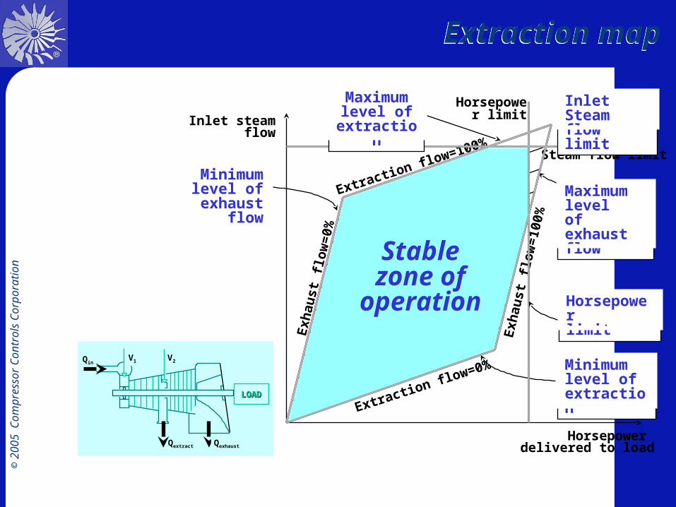
Horsepower delivered to load
Inlet steam flow
Extraction flow=0%
Exh
aust
flo
w=
0%
Constant extraction flow
Extraction flow=100%
Exh
aust
flo
w=
100%
Steam flow limit
Horsepower limit
Minimum level of extraction
Maximum level of exhaust flow
Horsepower limit
V1 V2
LOADLOAD
Qin
Qextract Qexhaust
Stable zone of
operation
Maximum level of
extraction
Minimum level of
exhaust flow
Inlet Steam flow limit
Extraction mapExtraction map

© 2
00
5
Com
pre
ssor
Contr
ols
Corp
ora
tion
Extraction Control. Three Arm LinkageExtraction Control. Three Arm Linkage

© 2
00
5
Com
pre
ssor
Contr
ols
Corp
ora
tion
horsepower
Inlet steam flow
LOAD
A
BC
D
Speed and extraction control. Loop interactions
Speed and extraction control. Loop interactions

© 2
00
5
Com
pre
ssor
Contr
ols
Corp
ora
tion
Inlet steam flow
PID
PID
V1
V2
Speed controller
A
B
1FT
3xSE
X
Extraction controller
horsepower
Integrating speed and extraction control. Load demand increase
Integrating speed and extraction control. Load demand increase

© 2
00
5
Com
pre
ssor
Contr
ols
Corp
ora
tion
Inlet steam flow
A
C
Speed controller
1FT
Extraction controller
PID
PID
V1
V2
3xSE
X
horsepower
Integrating speed and extraction control. Extraction demand increase
Integrating speed and extraction control. Extraction demand increase

© 2
00
5
Com
pre
ssor
Contr
ols
Corp
ora
tion
Objectives of Steam Management Control System
Objectives of Steam Management Control System
• Stable and tight control of HP and MP header pressure under all operating scenarios
• Meet the demands of all steam consumers• Satisfy the constraints of all turbines on the
headers• Minimize import of HP steam• Minimize letdown of steam from HP to MP
header• Minimize import of MP steam • Minimize letdown of steam from MP to LP
header

© 2
00
5
Com
pre
ssor
Contr
ols
Corp
ora
tion
Steam Management
System
Steam Management
System

© 2
00
5
Com
pre
ssor
Contr
ols
Corp
ora
tion
Steam Network ConfigurationSteam Network Configuration

© 2
00
5
Com
pre
ssor
Contr
ols
Corp
ora
tion
HP Steam header pressure HP Steam header pressure
HP Steam header pressure
103
103.5
104
104.5
105
105.5
0 50 100 150 200 250 300 350 400
Operating day Y2002
HP S
team
pre
ssur
e

© 2
00
5
Com
pre
ssor
Contr
ols
Corp
ora
tion
MP Steam header pressure MP Steam header pressure
MP Steam header pressure
20.7
20.75
20.8
20.85
20.9
20.95
21
21.05
0 100 200 300 400
Operating day Y2002
MP
Ste
am p
ress
ure

© 2
00
5
Com
pre
ssor
Contr
ols
Corp
ora
tion
LP Steam Header pressureLP Steam Header pressure
LP Steam header pressure
4
5
6
7
0 50 100 150 200 250 300 350 400
Operating day Y2002
LP S
team
pre
ssur
e

© 2
00
5
Com
pre
ssor
Contr
ols
Corp
ora
tion
Opportunity strikes again!Opportunity strikes again!
Variable Max Min AverageCracked gas boiler105 Bar steam (T/h)
330 242 291
105 Bar import (T/h) 69.5 0 21.7HP letdown valve
flow (T/h)24.6 6.4 14.2
30 Bar import (T/h) 16.8 3.4 5.7MP let down valve
flow (T/h)56.3 8.1 29.3
Steam Header Operating data Y2002

© 2
00
5
Com
pre
ssor
Contr
ols
Corp
ora
tion
Steam system constraints
Variable Min Max105 Bar Steam import 8.5 T/h 100 T/hHP letdown valve flow 5 T/h 120 T/h30 Bar Steam import 0 80 T/h
MP letdown valve flow 0 60 T/h105 Bar header
pressure103 Barg 110 Barg
22 Bar header pressure 19 Barg 22.5 Barg
Steam header constraint table

© 2
00
5
Com
pre
ssor
Contr
ols
Corp
ora
tion
Steam flow distribution - Existing control system
Steam flow distribution - Existing control system

© 2
00
5
Com
pre
ssor
Contr
ols
Corp
ora
tion
Flow redistribution - CCC Steam Management System
Flow redistribution - CCC Steam Management System

© 2
00
5
Com
pre
ssor
Contr
ols
Corp
ora
tion
Economic analysis - HP steam header
Economic analysis - HP steam header
Estimated reduction of HP Steam import
• Due to HP letdown losses = 6.8 T/h• HP & MP turbine optimization = 6 T/h• Total HP steam import reduction = 12.8 T/h• Percentage reduction = 58%
• Annual Savings = 1,800,000 Euro !!!

© 2
00
5
Com
pre
ssor
Contr
ols
Corp
ora
tion
Economic analysis - MP Steam header
Economic analysis - MP Steam header
Estimated reduction of MP Steam import
• Due to MP letdown losses = 5.6 T/h• Percentage reduction = 99%
• Annual Savings = 700,000 Euro

© 2
00
5
Com
pre
ssor
Contr
ols
Corp
ora
tion
Objectives of Steam Management Control System
Objectives of Steam Management Control System
• Stable and tight control of HP and MP header pressure under all operating scenarios
• Meet the demands of all steam consumers• Satisfy the constraints of all turbines on the
headers• Minimize import of HP auxiliary steam• Minimize letdown of steam from HP to MP
header• Minimize import of MP steam • Minimize letdown of steam from MP to LP
header

© 2
00
5
Com
pre
ssor
Contr
ols
Corp
ora
tion
Integrated Steam Network Control System
Integrated Steam Network Control System

© 2
00
5
Com
pre
ssor
Contr
ols
Corp
ora
tion
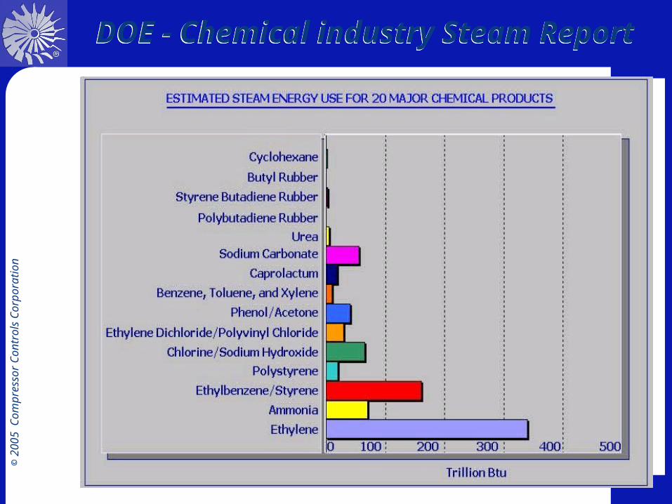
Market potentialMarket potential
• Factors– Huge Potential!
– Leverage our expertise in TMC
– Integration between Turbomachinery control system and Steam header network is the key
– Advanced constraint control management
• Major consumers of steam – Ethylene plants– Ammonia plants– Paper & pulp industry– Steel mills– Refineries
© 2
00
5
Com
pre
ssor
Contr
ols
Corp
ora
tion
DOE - Chemical industry Steam Report
DOE - Chemical industry Steam Report

© 2
00
5
Com
pre
ssor
Contr
ols
Corp
ora
tion
Value proposition for Smart Steam Management
Value proposition for Smart Steam Management

© 2
00
5
Com
pre
ssor
Contr
ols
Corp
ora
tion
ConclusionConclusion
• Audit steam flow distribution on different headers
• Basic issue of “Supply versus Demand”• Can import of HP & MP be reduced ?• Can letdown losses be cut down?• Understand steam flow and turbomachinery
constraints• Flow redistribution?• Focus on industries with significant Steam
consumption

© 2
00
5
Com
pre
ssor
Contr
ols
Corp
ora
tion
SPECIFICATIONS ERRORS

© 2
00
5
Com
pre
ssor
Contr
ols
Corp
ora
tion
Process Safety Design - 1987Process Safety Design - 1987
• HSE Study of 34 Industrial Accidents
• Most Common Cause: Specification Errors
Design and Implementation
15%
Operation and Maintenance
15%
Installation andCommissioning
6%
Specification 44%
Changes After Commissioning
21%

© 2
00
5
Com
pre
ssor
Contr
ols
Corp
ora
tion
SpecificationsSpecifications
• Writing a good, tight specification is very important
• Don’t just focus on the hardware
• Don’t fall into the instrument upgrade trap
• Demand value and try to specify it
• Focus on– System performance– Algorithms– Proven experience on similar applications

© 2
00
5
Com
pre
ssor
Contr
ols
Corp
ora
tion
Acceptance Test RequirementsAcceptance Test Requirements
• Acceptance test requirements for new control systems– Antisurge Control
• In response to full closure of a substation suction or discharge block valve, the system must not allow any compressor to surge.
• In response to the simultaneous closure of both suction and discharge block valves, the system should not allow any compressor to surge more than once.
– Discharge Pressure Control• In steady state, deviation of the discharge pressure from its
set point shall not exceed 0.5 %.
– Load-Sharing Control• In response to bringing a compressor on-line or taking one
off-line, the control system shall reestablish steady-state operation with all units equally loaded (within 1%) in no more than 30 minutes.

© 2
00
5
Com
pre
ssor
Contr
ols
Corp
ora
tion
Acceptance Test RequirementsAcceptance Test Requirements
– Turbine Speed Control• In steady state, deviation of the turbine speed from its
set point shall not exceed 0.5%.
– Turbine Limiting Control• In response to a rise in the speed set point, the system
shall not allow an increase in speed after the exhaust-gas temperature has exceeded its limiting control threshold by 0.5% of the sensor span.
• In response to a rise in the speed set point, the system shall not allow an increase in speed after the air-compressor discharge pressure has exceeded its limiting control threshold by 0.1% of the sensor span.
• In response to a rise in the speed set point, the system shall not allow an increase in speed after the uncontrolled shaft speed has exceeded its limiting control threshold by 0.5% of span.

© 2
00
5
Com
pre
ssor
Contr
ols
Corp
ora
tion
Specialized, high speed, digital turbomachinery control equipment
Specialized, high speed, digital turbomachinery control equipment
• Purpose-built hardware provides optimum performance
• Allows implementation of specialized algorithms, many patented
• Provides redundancy level required for customer’s application

© 2
00
5
Com
pre
ssor
Contr
ols
Corp
ora
tion
MTBF of Series 3 Plus controllers is 43.4 years, or 2.5 failures per
million hours of operation
Series 3 Plus PlatformSeries 3 Plus Platform
• Multi-loop controllers for speed, extraction, antisurge, & performance control
• Serial communications for peer to peer and host system communications

© 2
00
5
Com
pre
ssor
Contr
ols
Corp
ora
tion
• Series 4 features include:– Control multiple trains in one control system– I/O capacity tailored to each application– High speed communication links– Flexible fault
tolerance -simplex, duplex or triplex
– Highly configurable
Series 4 PlatformSeries 4 Platform
© 2
00
5
Com
pre
ssor
Contr
ols
Corp
ora
tion
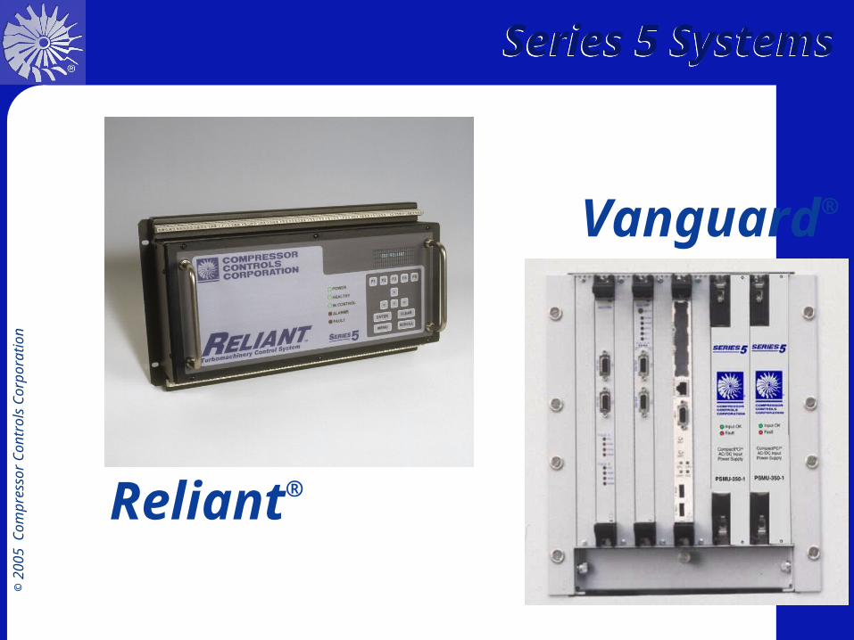
Vanguard®
Reliant®
Series 5 SystemsSeries 5 Systems

© 2
00
5
Com
pre
ssor
Contr
ols
Corp
ora
tion
• Design Screens
• Standard and Customized Screens
• On-Line Operation and Control
• Alarm and Event Management
• Critical Event Archiving Remote OnlookTM Diagnostics
Controller Overview
TrainView® Operator InterfaceTrainView® Operator Interface
Compressor Map Screen
Control System

© 2
00
5
Com
pre
ssor
Contr
ols
Corp
ora
tion
Guardian®
Overspeed Prevention SystemGuardian®
Overspeed Prevention System
• API 670 compliant
• CSA Certification– Class 1, Div 2, Groups A,B,C,D– Class 1, Zone 2, Exn IIC T4
• Enclosure IP-65 (NEMA 4)
• Alarms and history status
• Digital Tachometers for each Speed Module
• Flexible Mounting– 19” rack mount– Back mount

© 2
00
5
Com
pre
ssor
Contr
ols
Corp
ora
tion
Vantage®GPA Purpose-Built
Digital Governor for General-Purpose
Turbines
Specifically designed for condensing and back-pressure steam turbines driving synchronous generators.
Vantage®GD

© 2
00
5
Com
pre
ssor
Contr
ols
Corp
ora
tion
System Design & Consulting Services
System Design & Consulting Services
• Complete system design
• Right solution the first time
• Complete system documentation

© 2
00
5
Com
pre
ssor
Contr
ols
Corp
ora
tion
Field Engineering Services Field Engineering Services
• 94 Field engineers
• Expertise with processes, machinery and instrumentation
• Highly rated in customer satisfaction surveys
• Start-up services with on-going revenues

© 2
00
5
Com
pre
ssor
Contr
ols
Corp
ora
tion
CapabilitiesCapabilities
• Controlling over 7,000 turbomachines, including:– over 350 steam turbines– over 2,000 gas turbines
• 345 employees:– more than 200 engineers worldwide
• 19 PhDs • 60 Masters • 250 Bachelors• 47 full-time R&D personnel
• 13 Locations Worldwide

© 2
00
5
Com
pre
ssor
Contr
ols
Corp
ora
tion
Customers keep coming backCustomers keep coming back
80% of projects are from repeat
customers


