92
0103 Part No. X09-33240 XM capcom-europe.com M
0103 Part No. X09-33240 XM
capcom-europe.com
M
1
CONTROLLER SETUP . . . . . . . . . . . . . . . . . . . . . . . . . . . . . . . . . . . . . . . . . . . 2
Precautions . . . . . . . . . . . . . . . . . . . . . . . . . . . . . . . . . . . . . . . . . . . . 2
Troubleshooting . . . . . . . . . . . . . . . . . . . . . . . . . . . . . . . . . . . . . . . . . 2
Right Unit Assembly . . . . . . . . . . . . . . . . . . . . . . . . . . . . . . . . . . . . . . 2
Left Unit Assembly . . . . . . . . . . . . . . . . . . . . . . . . . . . . . . . . . . . . . . . 2
SECTION 1. VT CONCEPT AND SPECIAL PANZER DIVISION . . . . . . . . . . . . . . 4
1-1 VT Concept . . . . . . . . . . . . . . . . . . . . . . . . . . . . . . . . . . . . . . . . . . . 4
1-2 Basics of the Military Use VT . . . . . . . . . . . . . . . . . . . . . . . . . . . . . 4
1-3 Duties of the Special Armoured Unit . . . . . . . . . . . . . . . . . . . . . . 4
1-4 Special Panzer Division Formation . . . . . . . . . . . . . . . . . . . . . . . . 4
1-5 VT Platoon Operation . . . . . . . . . . . . . . . . . . . . . . . . . . . . . . . . . . 4
SECTION 2. VT SUMMARY . . . . . . . . . . . . . . . . . . . . . . . . . . . . . . . . . . . . . . . 5
2-1 Basic VT Parts . . . . . . . . . . . . . . . . . . . . . . . . . . . . . . . . . . . . . . . . 5
2-2 VT Operation System . . . . . . . . . . . . . . . . . . . . . . . . . . . . . . . . . . 5
2-3 VT Types . . . . . . . . . . . . . . . . . . . . . . . . . . . . . . . . . . . . . . . . . . . . 6
2-4 Movement . . . . . . . . . . . . . . . . . . . . . . . . . . . . . . . . . . . . . . . . . . 6
2-5 Fuel Tank and Spare Tanks . . . . . . . . . . . . . . . . . . . . . . . . . . . . . 6
2-6 Fuel Consumption and Estimated Movement Time . . . . . . . . . . . 6
2-7 Defensive Armour . . . . . . . . . . . . . . . . . . . . . . . . . . . . . . . . . . . . 6
2-8 Main Weapon and Sub Weapon . . . . . . . . . . . . . . . . . . . . . . . . . 6
2-9 Maximum Weapon Weight Allowance . . . . . . . . . . . . . . . . . . . . 6
2-10 Weapons Loaded on the VT . . . . . . . . . . . . . . . . . . . . . . . . . . . . 7
2-11 Targeting of Curve Trajectory Weapons on War Map . . . . . . . . 12
2-12 Short Fuse . . . . . . . . . . . . . . . . . . . . . . . . . . . . . . . . . . . . . . . . . . 12
2-13 Chaff Defence . . . . . . . . . . . . . . . . . . . . . . . . . . . . . . . . . . . . . . . 12
SECTION 3. SPECIAL FUNCTIONS
THROUGH 2ND GENERATION COOS . . . . . . . . . . . . . . . . . . . . . . . . . . . . . . 12
3-1 Additions for 2nd Generation COOS . . . . . . . . . . . . . . . . . . . . . . 12
3-2 FSS (Target Estimating Firing System) Function . . . . . . . . . . . . . . 12
3-3 Overdrive Function . . . . . . . . . . . . . . . . . . . . . . . . . . . . . . . . . . . 12
3-4 Stealth Function . . . . . . . . . . . . . . . . . . . . . . . . . . . . . . . . . . . . . . 12
3-5 Guided Weapons . . . . . . . . . . . . . . . . . . . . . . . . . . . . . . . . . . . . . 12
SECTION 4. VT CONTROLS . . . . . . . . . . . . . . . . . . . . . . . . . . . . . . . . . . . . . . 13
4-1 Startup Sequence . . . . . . . . . . . . . . . . . . . . . . . . . . . . . . . . . . . . . 13
4-2 When Stalling the VT During Startup . . . . . . . . . . . . . . . . . . . . . . 13
Basic Controls . . . . . . . . . . . . . . . . . . . . . . . . . . . . . . . . . . . . . . . . . . 14
4-3 Moving and Stopping . . . . . . . . . . . . . . . . . . . . . . . . . . . . . . . . . . 14
4-4 Acceleration and Deceleration . . . . . . . . . . . . . . . . . . . . . . . . . . 14
4-5 Rotation . . . . . . . . . . . . . . . . . . . . . . . . . . . . . . . . . . . . . . . . . . . . 14
4-6 Overdrive . . . . . . . . . . . . . . . . . . . . . . . . . . . . . . . . . . . . . . . . . . 14
4-7 Slidestep Function . . . . . . . . . . . . . . . . . . . . . . . . . . . . . . . . . . . . 14
4-8 Slidestep Functional Limitations . . . . . . . . . . . . . . . . . . . . . . . . . 14
4-9 Slidestep Tip Regulator . . . . . . . . . . . . . . . . . . . . . . . . . . . . . . . . 14
4-10 Cut-off Function . . . . . . . . . . . . . . . . . . . . . . . . . . . . . . . . . . . . . 14
4-11 Manipulator Controls . . . . . . . . . . . . . . . . . . . . . . . . . . . . . . . . . 15
VT Monitor . . . . . . . . . . . . . . . . . . . . . . . . . . . . . . . . . . . . . . . . . . . . 16
4-12 Main Camera Change . . . . . . . . . . . . . . . . . . . . . . . . . . . . . . . . . 16
4-13 Main Camera Dust and Dirt . . . . . . . . . . . . . . . . . . . . . . . . . . . . 16
4-14 Sub Monitor Functions . . . . . . . . . . . . . . . . . . . . . . . . . . . . . . . . 17
4-15 Night Vision Equipment . . . . . . . . . . . . . . . . . . . . . . . . . . . . . . . 17
JCS (Complete Command System) . . . . . . . . . . . . . . . . . . . . . . . . . . . 17
4-16 JCS (Complete Command System) Summary . . . . . . . . . . . . . . . 17
4-17 Multi-Monitor Display . . . . . . . . . . . . . . . . . . . . . . . . . . . . . . . . 18
4-18 Information Displayed in the Multi-Monitor . . . . . . . . . . . . . . . 18
Emergency Procedures . . . . . . . . . . . . . . . . . . . . . . . . . . . . . . . . . . . . . . . 19
4-19 Evacuation Setup . . . . . . . . . . . . . . . . . . . . . . . . . . . . . . . . . . . . 19
4-20 Emergency Eject Switch . . . . . . . . . . . . . . . . . . . . . . . . . . . . . . 19
4-21 Emergency Escape Procedures in Rivers or Seas . . . . . . . . . . . 19
4-22 Fire in the Hull . . . . . . . . . . . . . . . . . . . . . . . . . . . . . . . . . . . . . 19
SECTION 5. VT ATTACK . . . . . . . . . . . . . . . . . . . . . . . . . . . . . . . . . . . . . . . 20
5-1 Weapon Targeting and Shooting . . . . . . . . . . . . . . . . . . . . . . . . 20
5-2 Lock-On Function . . . . . . . . . . . . . . . . . . . . . . . . . . . . . . . . . . . . 20
5-3 Close Combat Targeting . . . . . . . . . . . . . . . . . . . . . . . . . . . . . . . 20
5-4 FSS (Target Estimating Firing System) . . . . . . . . . . . . . . . . . . . . . 21
5-5 Firing Ranges of Different Weapons . . . . . . . . . . . . . . . . . . . . . . 21
5-6 Notes on Firing Within Effective Target Range . . . . . . . . . . . . . . 21
5-7 Using Effective Target Range . . . . . . . . . . . . . . . . . . . . . . . . . . . . 22
5-8 Land Suppression Attack . . . . . . . . . . . . . . . . . . . . . . . . . . . . . . 22
5-9 Weapon Change . . . . . . . . . . . . . . . . . . . . . . . . . . . . . . . . . . . . . 22
5-10 Reloading Magazine Weapons . . . . . . . . . . . . . . . . . . . . . . . . . 22
SECTION 6. VT MOVEMENT . . . . . . . . . . . . . . . . . . . . . . . . . . . . . . . . . . . . 23
6-1 In General . . . . . . . . . . . . . . . . . . . . . . . . . . . . . . . . . . . . . . . . . . 23
6-2 Using Weather and Topography . . . . . . . . . . . . . . . . . . . . . . . . . 23
STEEL BATTALION CONTROLLER CONFIGURATION . . . . . . . . . . . . . . . . . . 24
SECTION 7. PLATOON STRATEGY PREPARATIONS . . . . . . . . . . . . . . . . . . . 26
7-1 Orders . . . . . . . . . . . . . . . . . . . . . . . . . . . . . . . . . . . . . . . . . . . . . 26
7-2 Mission Analysis . . . . . . . . . . . . . . . . . . . . . . . . . . . . . . . . . . . . . 26
7-3 Choosing Weapons . . . . . . . . . . . . . . . . . . . . . . . . . . . . . . . . . . . 26
7-4 Selection of Additional Armour and Sub-Weapons . . . . . . . . . . 26
7-5 Choosing your VT . . . . . . . . . . . . . . . . . . . . . . . . . . . . . . . . . . . . 26
7-6 Attaching Extra Fuel Tanks and Armour . . . . . . . . . . . . . . . . . . 26
7-7 Supply Requests . . . . . . . . . . . . . . . . . . . . . . . . . . . . . . . . . . . . . 26
7-8 Fixed VT Food Provisions . . . . . . . . . . . . . . . . . . . . . . . . . . . . . . 26
7-9 Bringing Personal Effects into the Cockpit . . . . . . . . . . . . . . . . . 26
SECTION 8. RADIO TRANSMISSIONS
8-1 Summary . . . . . . . . . . . . . . . . . . . . . . . . . . . . . . . . . . . . . . . . . . . 27
8-2 Pre-set Channels . . . . . . . . . . . . . . . . . . . . . . . . . . . . . . . . . . . . . 27
8-3 Radio Communication Procedures . . . . . . . . . . . . . . . . . . . . . . . 27
8-4 Sending a Message . . . . . . . . . . . . . . . . . . . . . . . . . . . . . . . . . . . 28
8-5 Receiving a Message . . . . . . . . . . . . . . . . . . . . . . . . . . . . . . . . . . 28
8-6 Repeating the Message . . . . . . . . . . . . . . . . . . . . . . . . . . . . . . . 28
SECTION 9. SUPPLY . . . . . . . . . . . . . . . . . . . . . . . . . . . . . . . . . . . . . . . . . . 29
9-1 Accepting Supplies . . . . . . . . . . . . . . . . . . . . . . . . . . . . . . . . . . . 29
9-2 Classifying Supplies . . . . . . . . . . . . . . . . . . . . . . . . . . . . . . . . . . 29
9-3 Supply via Supply Helicopter . . . . . . . . . . . . . . . . . . . . . . . . . . . 29
9-4 Choices and Cautions when Receiving Supplies . . . . . . . . . . . . 29
9-5 Opening of Supply Issuance Centre . . . . . . . . . . . . . . . . . . . . . . 29
SECTION 10. LEADERSHIP . . . . . . . . . . . . . . . . . . . . . . . . . . . . . . . . . . . . . . 30
10-1 Leadership Duties . . . . . . . . . . . . . . . . . . . . . . . . . . . . . . . . . . . 30
10-2 Necessary Qualities for a Commander . . . . . . . . . . . . . . . . . . . 30
10-3 Orders During Battle . . . . . . . . . . . . . . . . . . . . . . . . . . . . . . . . . 30
TECHNICAL APPENDIX . . . . . . . . . . . . . . . . . . . . . . . . . . . . . . . . . . . . . . . . 32
Cockpit: 1st Generation . . . . . . . . . . . . . . . . . . . . . . . . . . . . . . . . . . . 32
Main Monitor Display: 1st Generation . . . . . . . . . . . . . . . . . . . . . . . 32
Cockpit: 2nd Generation . . . . . . . . . . . . . . . . . . . . . . . . . . . . . . . . . . 33
Main Monitor Display: 2nd Generation . . . . . . . . . . . . . . . . . . . . . . 33
Cockpit: 3rd Generation . . . . . . . . . . . . . . . . . . . . . . . . . . . . . . . . . . 34
Main Monitor Display: 3rd Generation . . . . . . . . . . . . . . . . . . . . . . 34
Warranty . . . . . . . . . . . . . . . . . . . . . . . . . . . . . . . . . . . . . . . . . . . . . . 35
Customer Support . . . . . . . . . . . . . . . . . . . . . . . . . . . . . . . . . . . . . . 181
ENGLISHBEFORE PLAYING THE GAMEThank you for purchasing STEEL BATTALION. Make sure you readall the instruction manuals before playing the game. Afterreading the manuals, keep them nearby in a safe place so youcan refer to them quickly and easily.
WARNINGS• Store the unit and all components away from children.
• Do not open or modify the unit or components.
• Do not spill water on the unit or components.
• Store the unit and components in a dry, dust-free location.
• If a problem should arise, stop use immediately.
TABLE OF CONTENTS
SAFETY INFORMATIONABOUT PHOTOSENSITIVE SEIZURESA very small percentage of people may experience a seizurewhen exposed to certain visual images, including flashing lightsor patterns that may appear in video games. Even people whohave no history of seizures or epilepsy may have anundiagnosed condition that can cause these “photosensitiveepileptic seizures” while watching video games.
These seizures may have a variety of symptoms, includinglightheadedness, altered vision, eye or face twitching, jerking orshaking of arms or legs, disorientation, confusion, ormomentary loss of awareness. Seizures may also cause loss ofconsciousness or convulsions that can lead to injury fromfalling down or striking nearby objects.
Immediately stop playing and consult a doctor if you experienceany of these symptoms. Parents should watch for or ask theirchildren about the above symptoms—children and teenagers aremore likely than adults to experience these seizures.
The risk of photosensitive epileptic seizures may be reduced bysitting farther from the television screen, using a smallertelevision screen, playing in a well-lit room, and not playingwhen you are drowsy or fatigued.
If you or any of your relatives have a history of seizures orepilepsy, consult a doctor before playing.
Other Important Health and Safety Information. The XboxInstruction Manual contains important health and safetyinformation that you should read and understand before usingthis software.
AVOID DAMAGE TO YOUR TELEVISIONDo not use with certain televisions. Some televisions, especiallyfront- or rear-projection types, can be damaged if any videogames, including Xbox games, are played on them. Static imagespresented during the normal course of game play may “burn in”to the screen, causing a permanent shadow of the static imageto appear at all times, even when video games are not beingplayed. Similar damage may occur from static images createdwhen placing a video game on hold or pause. Consult yourtelevision owner’s manual to determine if video games can beplayed safely on your set. If you are unable to find thisinformation in the owner’s manual, contact your televisiondealer or the manufacturer to determine if video games can beplayed safely on your set.
Unauthorized copying, reverse engineering, transmission, publicperformance, rental, pay for play, or circumvention of copyprotection is strictly prohibited.
2 3
CONTROLLER SETUP
PRECAUTIONS• Do not plug more than 2 STEEL BATTALION controllers
into the same Xbox unit.
• Do not touch the aiming lever or selection lever whenconnecting the STEEL BATTALION controller or turningon the power.
• When attaching STEEL BATTALION controller pieces, donot mix up the left unit with the right unit. Be sure to attachthem in their correct positions.
• The STEEL BATTALION controller is made with small,precision parts. Do not put anything on it or place it on anunstable shelf.
• Always turn the Xbox console off before removing the STEELBATTALION controller.
• When cleaning the STEEL BATTALION controller, makesure you turn the power off beforehand. Clean the controllerwith a soft, dry towel. Do not use oil as it could cause fading orpossible deformation of the unit.
• Do not drop the STEEL BATTALION controller.
• Do not forcibly bend the cable, pull it out or place a heavy itemon it.
• When removing the cable, make sure you hold the area thatattaches to the Xbox console to pull out the cable.
• Do not store the STEEL BATTALION controller inlocations subject to extreme heat or cold, or where water ordampness could be present.
• Use the STEEL BATTALION controller for its intendedpurpose only.
TROUBLESHOOTINGBefore sending the STEEL BATTALION controller out to berepaired, please perform the following checks:
The controller does not respond –
• Reconnect the controller from the beginning and restart themachine.
The aiming lever LED light does not come on –
• Move the shift lever over to a position where the LED will lightup. Leaving the lever in a position where it will not light up forextended periods could cause the LED to stop lighting up.
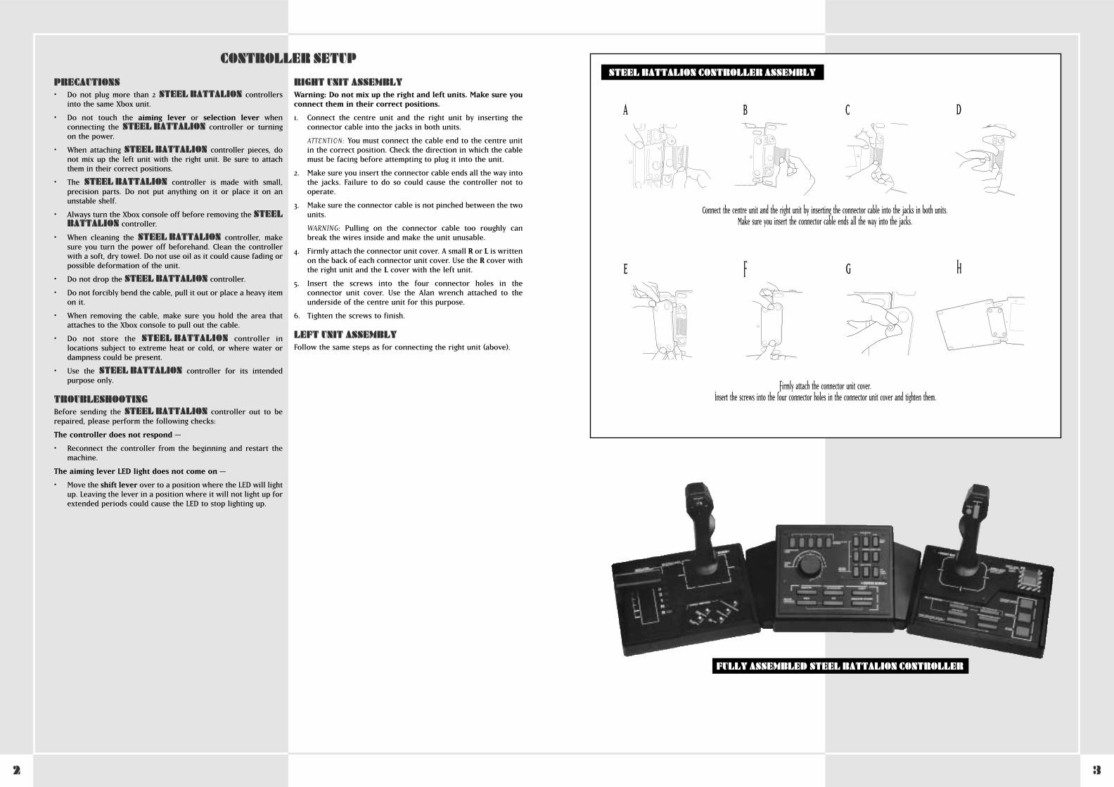
RIGHT UNIT ASSEMBLYWarning: Do not mix up the right and left units. Make sure youconnect them in their correct positions.
1. Connect the centre unit and the right unit by inserting theconnector cable into the jacks in both units.
ATTENTION: You must connect the cable end to the centre unitin the correct position. Check the direction in which the cablemust be facing before attempting to plug it into the unit.
2. Make sure you insert the connector cable ends all the way intothe jacks. Failure to do so could cause the controller not tooperate.
3. Make sure the connector cable is not pinched between the twounits.
WARNING: Pulling on the connector cable too roughly canbreak the wires inside and make the unit unusable.
4. Firmly attach the connector unit cover. A small R or L is writtenon the back of each connector unit cover. Use the R cover withthe right unit and the L cover with the left unit.
5. Insert the screws into the four connector holes in theconnector unit cover. Use the Alan wrench attached to theunderside of the centre unit for this purpose.
6. Tighten the screws to finish.
LEFT UNIT ASSEMBLYFollow the same steps as for connecting the right unit (above).
FULLY ASSEMBLED STEEL BATTALION CONTROLLER
STEEL BATTALION CONTROLLER ASSEMBLY
Connect the centre unit and the right unit by inserting the connector cable into the jacks in both units. Make sure you insert the connector cable ends all the way into the jacks.
Firmly attach the connector unit cover.Insert the screws into the four connector holes in the connector unit cover and tighten them.
A B C D
E F G H
4 5
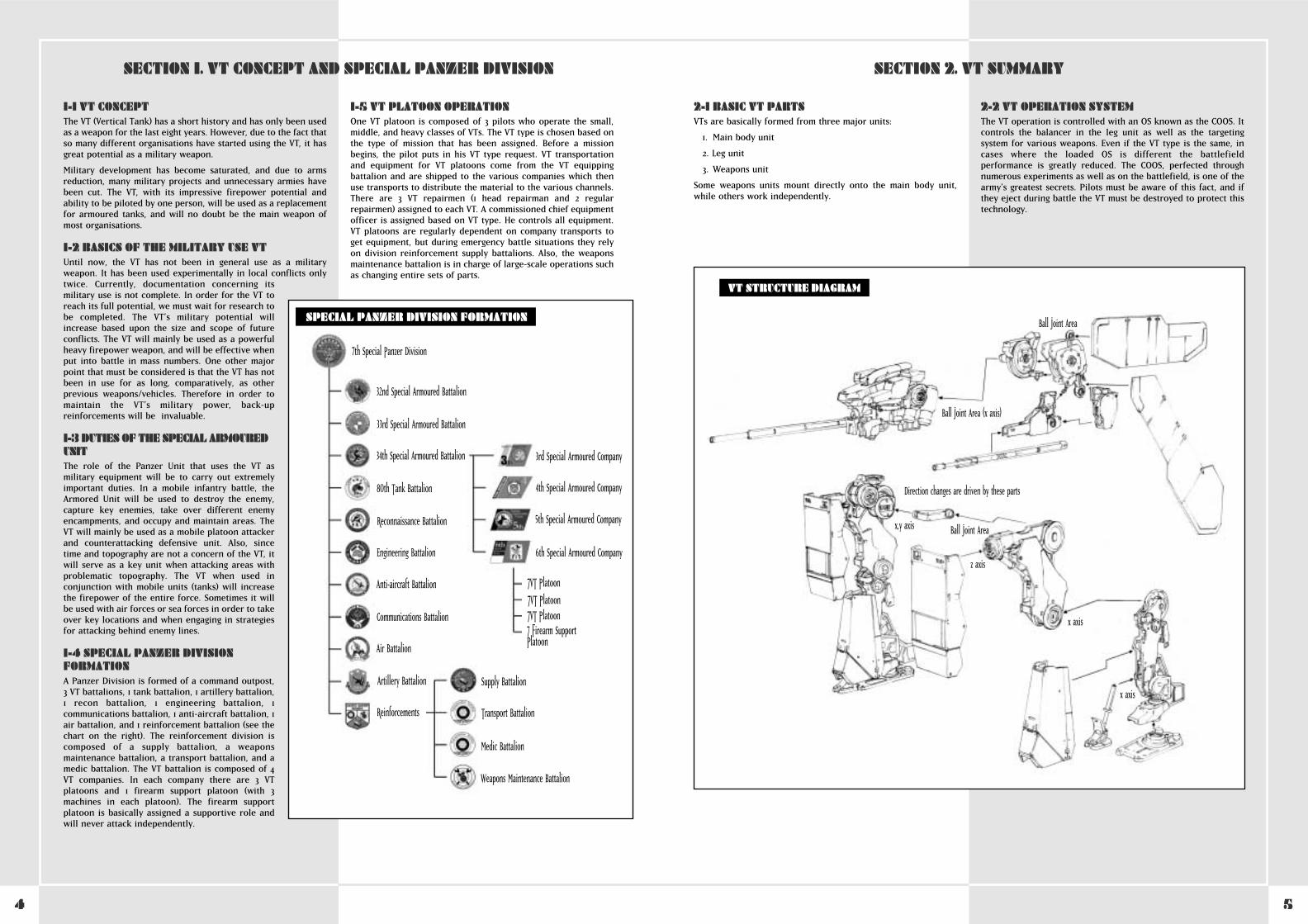
2-1 BASIC VT PARTSVTs are basically formed from three major units:
1. Main body unit
2. Leg unit
3. Weapons unit
Some weapons units mount directly onto the main body unit,while others work independently.
2-2 VT OPERATION SYSTEMThe VT operation is controlled with an OS known as the COOS. Itcontrols the balancer in the leg unit as well as the targetingsystem for various weapons. Even if the VT type is the same, incases where the loaded OS is different the battlefieldperformance is greatly reduced. The COOS, perfected throughnumerous experiments as well as on the battlefield, is one of thearmy’s greatest secrets. Pilots must be aware of this fact, and ifthey eject during battle the VT must be destroyed to protect thistechnology.
1-1 VT CONCEPTThe VT (Vertical Tank) has a short history and has only been usedas a weapon for the last eight years. However, due to the fact thatso many different organisations have started using the VT, it hasgreat potential as a military weapon.
Military development has become saturated, and due to armsreduction, many military projects and unnecessary armies havebeen cut. The VT, with its impressive firepower potential andability to be piloted by one person, will be used as a replacementfor armoured tanks, and will no doubt be the main weapon ofmost organisations.
1-2 BASICS OF THE MILITARY USE VTUntil now, the VT has not been in general use as a militaryweapon. It has been used experimentally in local conflicts onlytwice. Currently, documentation concerning itsmilitary use is not complete. In order for the VT toreach its full potential, we must wait for research tobe completed. The VT’s military potential willincrease based upon the size and scope of futureconflicts. The VT will mainly be used as a powerfulheavy firepower weapon, and will be effective whenput into battle in mass numbers. One other majorpoint that must be considered is that the VT has notbeen in use for as long, comparatively, as otherprevious weapons/vehicles. Therefore in order tomaintain the VT’s military power, back-upreinforcements will be invaluable.
1-3 DUTIES OF THE SPECIAL ARMOUREDUNIT The role of the Panzer Unit that uses the VT asmilitary equipment will be to carry out extremelyimportant duties. In a mobile infantry battle, theArmored Unit will be used to destroy the enemy,capture key enemies, take over different enemyencampments, and occupy and maintain areas. TheVT will mainly be used as a mobile platoon attackerand counterattacking defensive unit. Also, sincetime and topography are not a concern of the VT, itwill serve as a key unit when attacking areas withproblematic topography. The VT when used inconjunction with mobile units (tanks) will increasethe firepower of the entire force. Sometimes it willbe used with air forces or sea forces in order to takeover key locations and when engaging in strategiesfor attacking behind enemy lines.
1-4 SPECIAL PANZER DIVISIONFORMATIONA Panzer Division is formed of a command outpost,3 VT battalions, 1 tank battalion, 1 artillery battalion,1 recon battalion, 1 engineering battalion, 1communications battalion, 1 anti-aircraft battalion, 1air battalion, and 1 reinforcement battalion (see thechart on the right). The reinforcement division iscomposed of a supply battalion, a weaponsmaintenance battalion, a transport battalion, and amedic battalion. The VT battalion is composed of 4VT companies. In each company there are 3 VTplatoons and 1 firearm support platoon (with 3machines in each platoon). The firearm supportplatoon is basically assigned a supportive role andwill never attack independently.
1-5 VT PLATOON OPERATIONOne VT platoon is composed of 3 pilots who operate the small,middle, and heavy classes of VTs. The VT type is chosen based onthe type of mission that has been assigned. Before a missionbegins, the pilot puts in his VT type request. VT transportationand equipment for VT platoons come from the VT equippingbattalion and are shipped to the various companies which thenuse transports to distribute the material to the various channels.There are 3 VT repairmen (1 head repairman and 2 regularrepairmen) assigned to each VT. A commissioned chief equipmentofficer is assigned based on VT type. He controls all equipment.VT platoons are regularly dependent on company transports toget equipment, but during emergency battle situations they relyon division reinforcement supply battalions. Also, the weaponsmaintenance battalion is in charge of large-scale operations suchas changing entire sets of parts.
SECTION 1. VT CONCEPT AND SPECIAL PANZER DIVISION SECTION 2. VT SUMMARY
VT STRUCTURE DIAGRAM
Ball Joint Area (x axis)
x,y axis
z axis
x axis
x axis
Direction changes are driven by these parts
Ball Joint Area
Ball Joint Area
7th Special Panzer Division
32nd Special Armoured Battalion
33rd Special Armoured Battalion
34th Special Armoured Battalion 3rd Special Armoured Company
4th Special Armoured Company
5th Special Armoured Company
6th Special Armoured Company
‡VT Platoon‡VT Platoon‡VT Platoon‡ Firearm SupportPlatoon
Supply Battalion
Transport Battalion
Medic Battalion
Weapons Maintenance Battalion
80th Tank Battalion
Reconnaissance Battalion
Engineering Battalion
Anti-aircraft Battalion
Communications Battalion
Air Battalion
Artillery Battalion
Reinforcements
SPECIAL PANZER DIVISION FORMATION
6 7
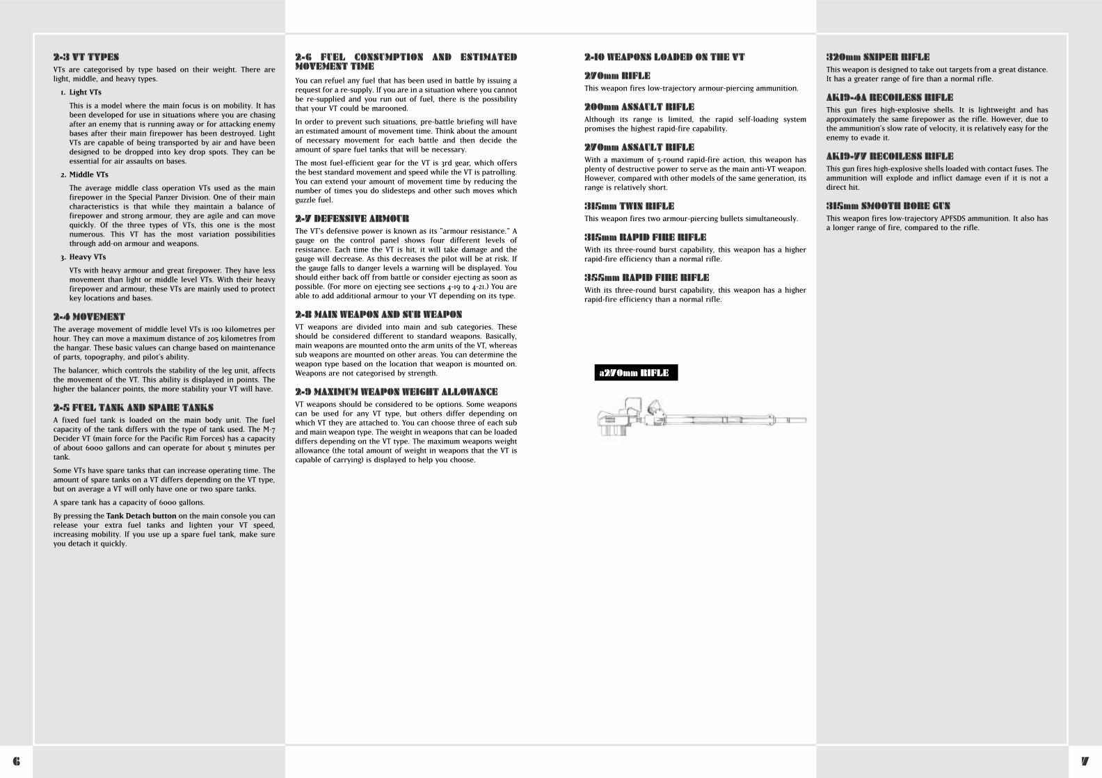
2-10 WEAPONS LOADED ON THE VT
270mm RIFLEThis weapon fires low-trajectory armour-piercing ammunition.
200mm ASSAULT RIFLEAlthough its range is limited, the rapid self-loading systempromises the highest rapid-fire capability.
270mm ASSAULT RIFLEWith a maximum of 5-round rapid-fire action, this weapon hasplenty of destructive power to serve as the main anti-VT weapon.However, compared with other models of the same generation, itsrange is relatively short.
315mm TWIN RIFLEThis weapon fires two armour-piercing bullets simultaneously.
315mm RAPID FIRE RIFLEWith its three-round burst capability, this weapon has a higherrapid-fire efficiency than a normal rifle.
355mm RAPID FIRE RIFLEWith its three-round burst capability, this weapon has a higherrapid-fire efficiency than a normal rifle.
320mm SNIPER RIFLEThis weapon is designed to take out targets from a great distance.It has a greater range of fire than a normal rifle.
AK19-4A RECOILESS RIFLEThis gun fires high-explosive shells. It is lightweight and hasapproximately the same firepower as the rifle. However, due tothe ammunition’s slow rate of velocity, it is relatively easy for theenemy to evade it.
AK19-77 RECOILESS RIFLEThis gun fires high-explosive shells loaded with contact fuses. Theammunition will explode and inflict damage even if it is not adirect hit.
315mm SMOOTH BORE GUNThis weapon fires low-trajectory APFSDS ammunition. It also hasa longer range of fire, compared to the rifle.
2-3 VT TYPESVTs are categorised by type based on their weight. There arelight, middle, and heavy types.
1. Light VTs
This is a model where the main focus is on mobility. It hasbeen developed for use in situations where you are chasingafter an enemy that is running away or for attacking enemybases after their main firepower has been destroyed. LightVTs are capable of being transported by air and have beendesigned to be dropped into key drop spots. They can beessential for air assaults on bases.
2. Middle VTs
The average middle class operation VTs used as the mainfirepower in the Special Panzer Division. One of their maincharacteristics is that while they maintain a balance offirepower and strong armour, they are agile and can movequickly. Of the three types of VTs, this one is the mostnumerous. This VT has the most variation possibilitiesthrough add-on armour and weapons.
3. Heavy VTs
VTs with heavy armour and great firepower. They have lessmovement than light or middle level VTs. With their heavyfirepower and armour, these VTs are mainly used to protectkey locations and bases.
2-4 MOVEMENTThe average movement of middle level VTs is 100 kilometres perhour. They can move a maximum distance of 205 kilometres fromthe hangar. These basic values can change based on maintenanceof parts, topography, and pilot’s ability.
The balancer, which controls the stability of the leg unit, affectsthe movement of the VT. This ability is displayed in points. Thehigher the balancer points, the more stability your VT will have.
2-5 FUEL TANK AND SPARE TANKSA fixed fuel tank is loaded on the main body unit. The fuelcapacity of the tank differs with the type of tank used. The M-7Decider VT (main force for the Pacific Rim Forces) has a capacityof about 6000 gallons and can operate for about 5 minutes pertank.
Some VTs have spare tanks that can increase operating time. Theamount of spare tanks on a VT differs depending on the VT type,but on average a VT will only have one or two spare tanks.
A spare tank has a capacity of 6000 gallons.
By pressing the Tank Detach button on the main console you canrelease your extra fuel tanks and lighten your VT speed,increasing mobility. If you use up a spare fuel tank, make sureyou detach it quickly.
2-6 FUEL CONSUMPTION AND ESTIMATEDMOVEMENT TIMEYou can refuel any fuel that has been used in battle by issuing arequest for a re-supply. If you are in a situation where you cannotbe re-supplied and you run out of fuel, there is the possibilitythat your VT could be marooned.
In order to prevent such situations, pre-battle briefing will havean estimated amount of movement time. Think about the amountof necessary movement for each battle and then decide theamount of spare fuel tanks that will be necessary.
The most fuel-efficient gear for the VT is 3rd gear, which offersthe best standard movement and speed while the VT is patrolling.You can extend your amount of movement time by reducing thenumber of times you do slidesteps and other such moves whichguzzle fuel.
2-7 DEFENSIVE ARMOURThe VT’s defensive power is known as its “armour resistance.” Agauge on the control panel shows four different levels ofresistance. Each time the VT is hit, it will take damage and thegauge will decrease. As this decreases the pilot will be at risk. Ifthe gauge falls to danger levels a warning will be displayed. Youshould either back off from battle or consider ejecting as soon aspossible. (For more on ejecting see sections 4-19 to 4-21.) You areable to add additional armour to your VT depending on its type.
2-8 MAIN WEAPON AND SUB WEAPONVT weapons are divided into main and sub categories. Theseshould be considered different to standard weapons. Basically,main weapons are mounted onto the arm units of the VT, whereassub weapons are mounted on other areas. You can determine theweapon type based on the location that weapon is mounted on.Weapons are not categorised by strength.
2-9 MAXIMUM WEAPON WEIGHT ALLOWANCEVT weapons should be considered to be options. Some weaponscan be used for any VT type, but others differ depending onwhich VT they are attached to. You can choose three of each suband main weapon type. The weight in weapons that can be loadeddiffers depending on the VT type. The maximum weapons weightallowance (the total amount of weight in weapons that the VT iscapable of carrying) is displayed to help you choose.
a270mm RIFLE
89
SQUALL - ANTI-VT GUIDED MORTARThis is the only high-angle fire anti-VT weapon that has homingcapability.
RAILGUN AThis is the most recent weapon developed by the PRF. With theuse of an electro-magnetic pulse, this weapon fires its ammo athypervelocity speeds. It has an unparalleled long attack rangeand firepower.
RAILGUN BA railgun developed by the Hai Shi Dao. With the use of anelectro-magnetic pulse, this weapon fires its ammo athypervelocity speeds. It has an unparalleled long attack rangeand firepower.
HVM LAUNCHERThis weapon fires jet propelled armour-piercing ammunition.Although its range and firepower are of the highest class, it is notequipped with a homing system.
225mm HOWITZERThis weapon fires grenade shells in a high-arc trajectory.Although not too destructive, it is capable of inflicting damage ina fixed radius upon impact. It is very effective against populatedareas of AFVs.
305mm HOWITZERThis weapon fires grenade shells in a high-arc trajectory.Although not terribly destructive, it is capable of inflictingdamage in a fixed radius upon impact. It is very effective againstpopulated areas of AFVs.
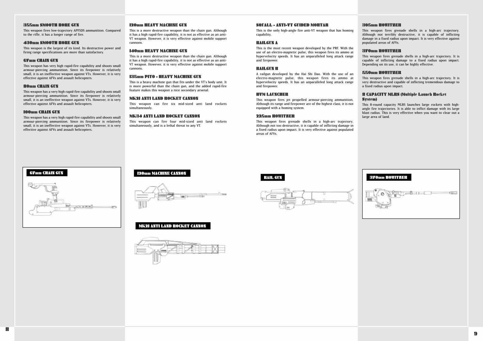
370mm HOWITZERThis weapon fires grenade shells in a high-arc trajectory. It iscapable of inflicting damage to a fixed radius upon impact.Depending on its use, it can be highly effective.
550mm HOWITZERThis weapon fires grenade shells in a high-arc trajectory. It isvery destructive and capable of inflicting tremendous damage toa fixed radius upon impact.
8 CAPACITY MLRS (Multiple Launch RocketSystem)This 8-round capacity MLRS launches large rockets with high-angle fire trajectories. It is able to inflict damage with its largeblast radius. This is very effective when you want to clear out alarge area of land.
355mm SMOOTH BORE GUNThis weapon fires low-trajectory APFSDS ammunition. Comparedto the rifle, it has a longer range of fire.
430mm SMOOTH BORE GUNThis weapon is the largest of its kind. Its destructive power andfiring range specifications are more than satisfactory.
67mm CHAIN GUNThis weapon has very high rapid-fire capability and shoots smallarmour-piercing ammunition. Since its firepower is relativelysmall, it is an ineffective weapon against VTs. However, it is veryeffective against AFVs and assault helicopters.
80mm CHAIN GUNThis weapon has a very high rapid-fire capability and shoots smallarmour-piercing ammunition. Since its firepower is relativelysmall, it is an ineffective weapon against VTs. However, it is veryeffective against AFVs and assault helicopters.
100mm CHAIN GUNThis weapon has a very high rapid-fire capability and shoots smallarmour-piercing ammunition. Since its firepower is relativelysmall, it is an ineffective weapon against VTs. However, it is veryeffective against AFVs and assault helicopters.
120mm HEAVY MACHINE GUNThis is a more destructive weapon than the chain gun. Althoughit has a high rapid-fire capability, it is not as effective as an anti-VT weapon. However, it is very effective against mobile supportcannons.
140mm HEAVY MACHINE GUNThis is a more destructive weapon than the chain gun. Althoughit has a high rapid-fire capability, it is not as effective as an anti-VT weapon. However, it is very effective against mobile supportcannons.
135mm PITO - HEAVY MACHINE GUNThis is a heavy machine gun that fits under the VT’s body unit. Itis more powerful than the chain gun, and the added rapid-firefeature makes this weapon a nice secondary arsenal.
MK21 ANTI LAND ROCKET CANNONThis weapon can fire six mid-sized anti land rocketssimultaneously.
MK34 ANTI LAND ROCKET CANNONThis weapon can fire four mid-sized anti land rocketssimultaneously, and is a lethal threat to any VT.
67mm CHAIN GUNRAIL GUN 370mm HOWITZER
120mm MACHINE CANNON
MK21 ANTI LAND ROCKET CANNON
10 11
FLAME THROWERThis is a close combat weapon that attaches beneath the VT’sbody unit. A direct hit with this weapon will cause a VT toexplode in flames.
STUN RODDesigned especially for close combat with VTs, a direct hit withthis weapon will cause massive volts of electricity that willincapacitate the enemy VT temporarily.
CUTTER BOOMThis large cutter boom is retrofitted for a VT for close combat. Itis the most destructive close-combat weapon.
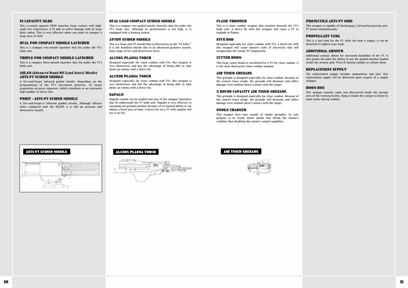
AIR TIMED GRENADEThis grenade is designed especially for close combat. Because ofthe contact fuses inside, the grenade will detonate and inflictdamage even without direct contact with the target.
3 ROUND CAPACITY AIR TIMED GRENADEThis grenade is designed especially for close combat. Because ofthe contact fuses inside, the grenade will detonate and inflictdamage even without direct contact with the target.
SMOKE CHARGERThis weapon fires four rounds of smoke grenades. Its solepurpose is to create dense smoke that blinds the enemy’svisibility thus disabling the enemy’s attack capability.
PROJECTILE ANTI-VT MINEThis weapon is capable of discharging 3 forward-projecting anti-VT mines simultaneously.
PROPELLANT TANKThis is a fuel tank for the VT. After the tank is empty, it can bedetached to lighten your load.
ADDITIONAL ARMOURAdditional armour allows for increased durability of the VT. Italso grants the pilot the ability to use the guided missiles loadedinside the armour pod. Press F1 during combat to release them.
REPLACEMENT SUPPLYThe replacement supply includes ammunition and fuel. Onereplacement supply will be delivered upon request of a supplychopper.
BOOM BOXThis antique cassette radio was discovered inside the storagearea of the training facility. Hang it inside the cockpit to listen tosome tunes during combat.
12 CAPACITY MLRSThis 12-round capacity MLRS launches large rockets with high-angle fire trajectories. It IS able to inflict damage with its largeblast radius. This is very effective when you want to conquer alarge area of land.
DUAL POD COMPACT MISSILE LAUNCHERThis is a compact two-missile launcher that fits under the VT’sbody unit.
TRIPLE POD COMPACT MISSILE LAUNCHERThis is a compact three-missile launcher that fits under the VT’sbody unit.
ASLAM (Advanced Stand 0ff Land Attack Missile)ANTI-VT GUIDED MISSILEA fire-and-forget infrared guided missile. Depending on theprogramming of the VT’s movement patterns, its targetacquisition accuracy improves, which translates to an extremelyhigh number of direct hits.
POZIT - ANTI-VT GUIDED MISSILEA fire-and-forget-it infrared guided missile. Although inferiorwhen compared with the ASLAM, it is still an accurate anddestructive missile.
DUAL LOAD COMPACT GUIDED MISSILEThis is a compact two-guided-missile launcher that fits under theVT’s body unit. Although its performance is not high, it isequipped with a homing system.
AVTDV GUIDED MISSILEThis is a large anti-VT missile that is also known as the "VT killer.”It is the deadliest missile due to its advanced guidance system,long range of fire and destructive force.
ALC205 PLASMA TORCHDesigned especially for close combat with VTs, this weapon isvery destructive and has the advantage of being able to takedown an enemy with a direct hit.
ALC22B PLASMA TORCHDesigned especially for close combat with VTs, this weapon isvery destructive and has the advantage of being able to takedown an enemy with a direct hit.
NAPALMNapalm rounds can be loaded into any of the compact launchersthat fit underneath the VT body unit. Napalm is very effective insweeping out ground enemies because of its natural ability to setablaze a fixed area of land. A direct hit on a VT with napalm willset it on fire.
ALC205 PLASMA TORCHANTI-VT GUIDED MISSILE AIR TIMED GRENADE
12 13
2-11 TARGETING OF CURVE TRAJECTORYWEAPONS ON WAR MAPYou should lock-on your target beforehand when using a weaponthat uses a curved firing trajectory. When you choose a curvedfiring trajectory weapon, the target, firing direction, and wherethe weapon will land will be displayed in a white line on the WarMap. You can use this information to attempt to hit the enemyeven when you are not locked on.
2-12 SHORT FUSEIn ammo for the Ak19-77 non-recoil cannon and in short-rangegrenades, a short fuse has been set (a contact fuse would typicallybe used for normal artillery). Short fuses use magnetism to findtheir targets and then explode once they are within a setdistance. Thanks to this, you do not have to hit the target directlyto damage it. In a battle of quick, mobile VTs, these short fusescan play a great support role in damaging the opponent.
2-13 CHAFF DEFENCETo defend against radar guided missiles, the VT has beenequipped with a chaff dispensing unit. The chaff explodes into 4different directions after the VT has been fired upon by a missile.Aluminium shards explode into the air and the guided missilelocks onto the chaff, making the missile miss its target.
If you perform a side-step after you release the chaff, you candodge the missile more effectively.
SECTION 3. SPECIAL FUNCTIONSTHROUGH 2ND GENERATION COOS
CURVED TRAJECTORY VS STRAIGHT TRAJECTORY
Curved Trajectory
Straight Trajectory
3-1 ADDITIONS FOR 2ND GENERATION COOSCurrently the COOS that powers all the VT’s movements hasswitched over to the 2nd generation and has increased thefunctionality of the VT’s abilities. Beside an increase in processorpower, the COOS has new anti-VT guidance weapons loaded, anda usable Target Estimating Firing System (FSS). These newadditions give the VT even more destructive power. Below is alisting of many of the 2nd generation COOS’s functions.
3-2 FSS (Target Estimating Firing System)FUNCTIONThe FSS analyses the target VT’s movement pattern, the distanceof bullet flight and amount of time the round will be in the air. Itthen automatically moves the target finder onto the enemy’s nextprobable location. The FSS targeting mode and regular "straighttargeting" can be switched by pressing the FSS button. Checksection 5-4 for more information about the FSS.
3-3 OVERDRIVE FUNCTIONThis function is used to give the VT a speed increase for a limitedtime. It turns off the "speed limiter" that protects various jointsfrom wear and tear. For more information of the overdrivefunction, check section 4-6.
3-4 STEALTH FUNCTIONA stealth function included in the VT allows it to avoid beingcaught on radar. This is accomplished using radar absorbentpaint, improving gas releasing ducts, and making the main hullmore aerodynamic.
3-5 GUIDED WEAPONSOne of the major new characteristics of the 2nd generation COOSis the increased use of guided weapons. New anti-VT guidedmissiles have been added to the already established Laser ActiveGuidance System. This system analyses VT movement patternsand predicts the enemy’s next location using the FSS in real-time,increasing hit accuracy. It is expected that the new system will behighly effective in anti-VT battles.
4-1 STARTUP SEQUENCEWhen you first enter a VT before moving it into battle, the VTbattery, its fuel tank and weapons are at maximum capacity. TheVT startup sequence is listed below.
1. Close the Cockpit Hatch
Press the Cockpit Hatch button on the right side. Be sure tocheck whether the cockpit hatch is closed or open.
2. Press the Ignition Button
Press the Ignition button below the Cockpit Hatch button.The engine will start and power will flow into the cockpitfrom the generator. The VT’s OS comes online and a simplecheck of the functions is automatically displayed on thescreen before the Startup Function screen.
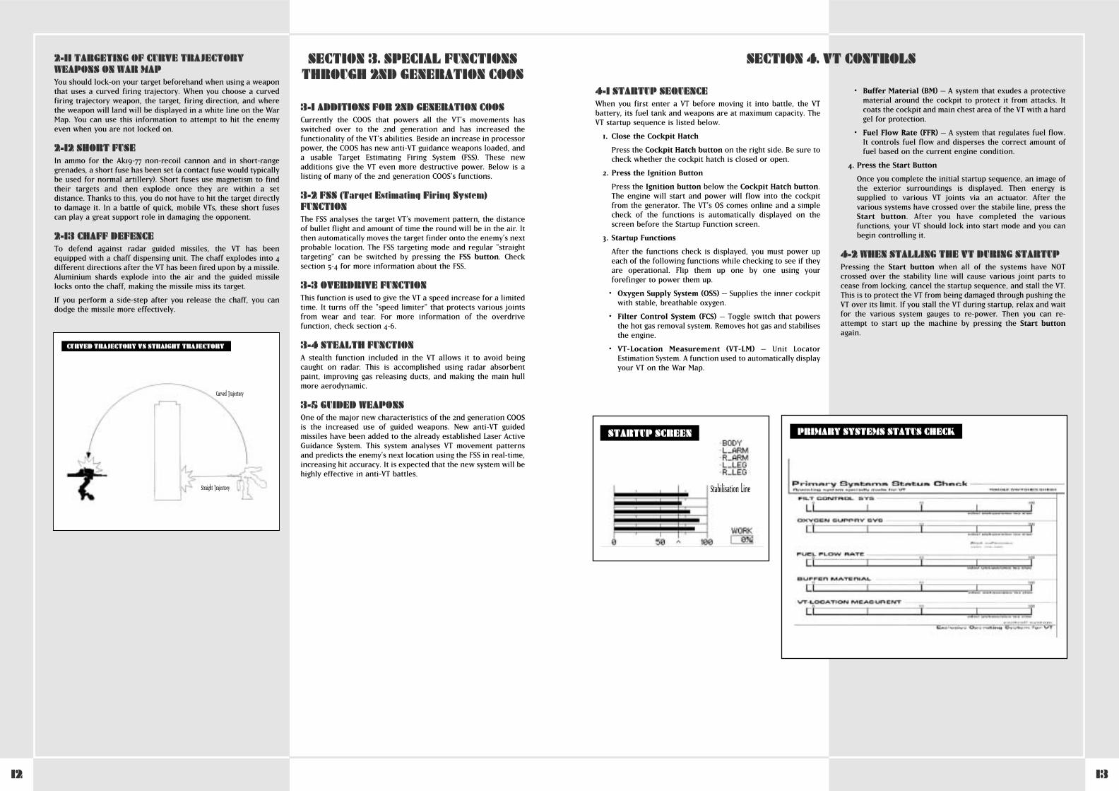
3. Startup Functions
After the functions check is displayed, you must power upeach of the following functions while checking to see if theyare operational. Flip them up one by one using yourforefinger to power them up.
• Oxygen Supply System (OSS) – Supplies the inner cockpitwith stable, breathable oxygen.
• Filter Control System (FCS) – Toggle switch that powersthe hot gas removal system. Removes hot gas and stabilisesthe engine.
• VT-Location Measurement (VT-LM) – Unit LocatorEstimation System. A function used to automatically displayyour VT on the War Map.
• Buffer Material (BM) – A system that exudes a protectivematerial around the cockpit to protect it from attacks. Itcoats the cockpit and main chest area of the VT with a hardgel for protection.
• Fuel Flow Rate (FFR) – A system that regulates fuel flow.It controls fuel flow and disperses the correct amount offuel based on the current engine condition.
4. Press the Start Button
Once you complete the initial startup sequence, an image ofthe exterior surroundings is displayed. Then energy issupplied to various VT joints via an actuator. After thevarious systems have crossed over the stabile line, press theStart button. After you have completed the variousfunctions, your VT should lock into start mode and you canbegin controlling it.
4-2 WHEN STALLING THE VT DURING STARTUPPressing the Start button when all of the systems have NOTcrossed over the stability line will cause various joint parts tocease from locking, cancel the startup sequence, and stall the VT.This is to protect the VT from being damaged through pushing theVT over its limit. If you stall the VT during startup, relax and waitfor the various system gauges to re-power. Then you can re-attempt to start up the machine by pressing the Start buttonagain.
SECTION 4. VT CONTROLS
Stabilisation Line
STARTUP SCREEN PRIMARY SYSTEMS STATUS CHECK
14 15
BASIC CONTROLS4-3 MOVING AND STOPPINGMoving and stopping are the two most basic movements of the VT.You can shift the gear lever from 1st to 5th speeds. Pressing theaccelerator increases the engine’s RPMs and the VT movesforward. You can shift the gear lever into reverse to movebackward. You stop the VT by taking your foot off theaccelerator and pushing down on the brake pedal. If you makesharp turns while moving at high speeds your VT can tip over, sobe careful.
4-4 ACCELERATION AND DECELERATIONThe amount of acceleration and deceleration depends on theamount of pressure you apply to the accelerator. Brakes areused by pressing the brake pedal or through downshifting. Inneutral your VT will be at 0 mph. With each gear level you gainmore speed but lose torque. On areas where your speed is notincreasing smoothly you may want to downshift for better fuelefficiency. Shifting the gear lever into reverse reverses the VT.
4-5 ROTATIONRotating the VT is performed by pressing the left rotation handle� or �. The rotation speed increases based on the amount therotation stick is pressed in either direction. If the balancercannot maintain total VT balance then the VT will tip over, so becareful.
4-6 OVERDRIVEThis function was developed after several skilled pilots requestedit. It disables the speed limiter that protects various joints fromwear and tear, resulting in an increase in speed. The limiter lockis turned off when you press the Overdrive button. Pressing theOverdrive button again reactivates the lock. When the VT is inoverdrive, its fuel consumption is triple the amount of normaloperation, so be careful when using it.
4-7 SLIDESTEP FUNCTIONThis is the one of the VT’s special ways of dodging incomingfirepower. It is a major difference between the VT and a regulartank. You can quickly move to the right or left using the OS’sprogramming. You can also use this function to quickly regain
balance in the event that your VT is about to tip over. Theslidestep is used as a quick motion to one of four directions usingpre-programmed paths. It is carried out by a combination ofaccelerating and using the balancer. The balancer automaticallystrengthens the joints/areas that will take the brunt of the wearand tear. The slidestep is performed by pressing the rotationlever� or � while simultaneously pressing the slidestep pedal.The slidestep is a great way to dodge an enemy attack. Anothermovement can be accomplished by leaving the rotation lever inneutral and pressing the slidestep pedal. This will cause your VTto do a forward dash. Performing this function while in reverseresults in a back dash.
4-8 SLIDESTEP FUNCTIONAL LIMITATIONSPerforming a slidestep places great stress on the joint sections ofthe VT. To decrease wear and tear, a large of amount of energy isused via the actuator. Energy originating in the generator is thenrecycled to the main battery, but the battery power is greatlyreduced each time a slidestep is performed. In cases where thereis not enough power, the slidestep is automatically cancelled.When the battery is running low, a heat warning is displayed. Donot use a slidestep when this is displayed.
4-9 SLIDESTEP TIP REGULATORWhenever the VT movement exceeds the balancer’s limits, thereis the possibility that the VT will tip over. Tipping occurs throughreckless operation or sharp turning at high speeds. It can alsooccur when an enemy hit is taken. Whenever tipping seems likelyto occur, pressing the slidestep pedal will re-balance the VT.However, if the VT is low in battery power it will be unable to usethis manoeuvre. If you do happen to tip over, releasing theaccelerator and then pressing it again it will make your VT standback up.
4-10 CUT-OFF FUNCTIONIn cases where you incur damage that exceeds max damagecapacity, your VT will automatically power down (cut-off) toprotect various joint sections from further harm. When a cut-offoccurs, all locks are undone and the VT stalls. You must thenquickly run through the startup sequence again to re-power theVT.
SLIDESTEP FUNCTION
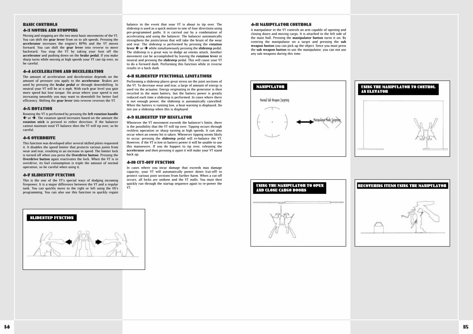
4-11 MANIPULATOR CONTROLSA manipulator in the VT controls an arm capable of opening andclosing doors and moving cargo. It is attached to the left side ofthe main hull. Pressing the manipulator button turns it on. Bycentring the manipulator on a target and pressing the subweapon button you can pick up the object. Since you must pressthe sub weapon button to use the manipulator, you can not useany sub weapons during this time.
MANIPULATOR
Normal Sub Weapon Targeting
Manipulator Mode Targeting
USING THE MANIPULATOR TO OPENAND CLOSE CARGO DOORS
USING THE MANIPULATOR TO CONTROLAN ELEVATOR
RECOVERING ITEMS USING THE MANIPULATOR
16 17
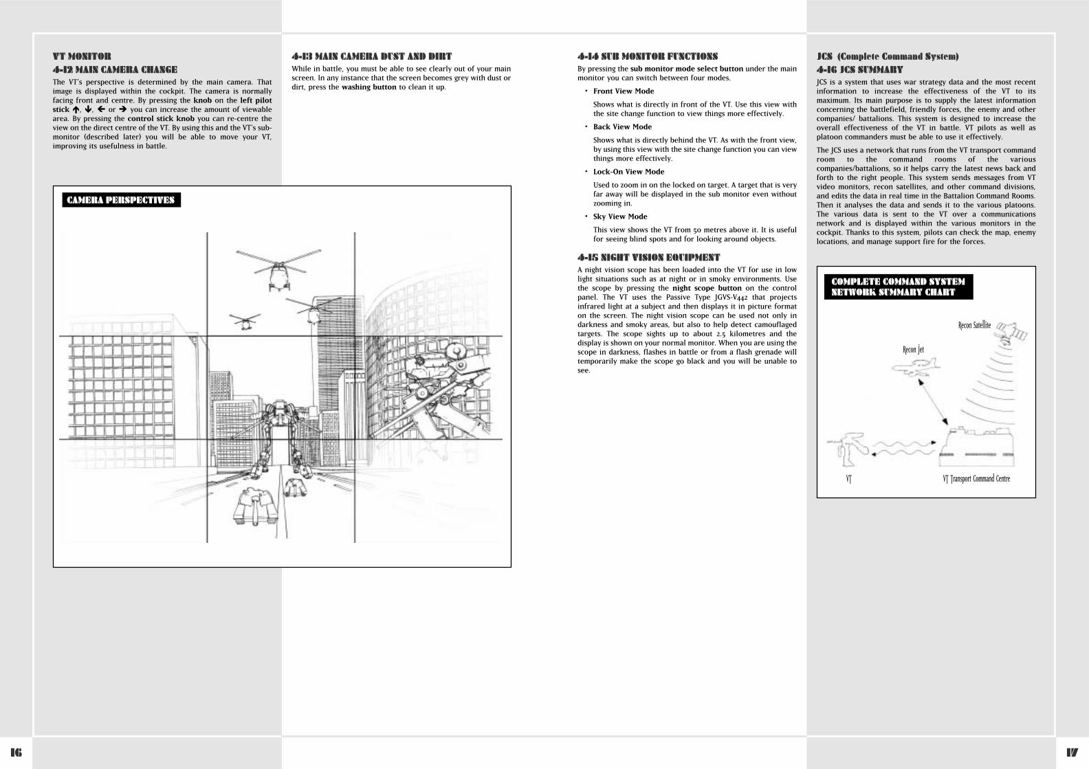
VT MONITOR4-12 MAIN CAMERA CHANGEThe VT’s perspective is determined by the main camera. Thatimage is displayed within the cockpit. The camera is normallyfacing front and centre. By pressing the knob on the left pilotstick �, �, � or � you can increase the amount of viewablearea. By pressing the control stick knob you can re-centre theview on the direct centre of the VT. By using this and the VT’s sub-monitor (described later) you will be able to move your VT,improving its usefulness in battle.
4-13 MAIN CAMERA DUST AND DIRTWhile in battle, you must be able to see clearly out of your mainscreen. In any instance that the screen becomes grey with dust ordirt, press the washing button to clean it up.
CAMERA PERSPECTIVES
4-14 SUB MONITOR FUNCTIONSBy pressing the sub monitor mode select button under the mainmonitor you can switch between four modes.
• Front View Mode
Shows what is directly in front of the VT. Use this view withthe site change function to view things more effectively.
• Back View Mode
Shows what is directly behind the VT. As with the front view,by using this view with the site change function you can viewthings more effectively.
• Lock-On View Mode
Used to zoom in on the locked on target. A target that is veryfar away will be displayed in the sub monitor even withoutzooming in.
• Sky View Mode
This view shows the VT from 50 metres above it. It is usefulfor seeing blind spots and for looking around objects.
4-15 NIGHT VISION EQUIPMENTA night vision scope has been loaded into the VT for use in lowlight situations such as at night or in smoky environments. Usethe scope by pressing the night scope button on the controlpanel. The VT uses the Passive Type JGVS-V442 that projectsinfrared light at a subject and then displays it in picture formaton the screen. The night vision scope can be used not only indarkness and smoky areas, but also to help detect camouflagedtargets. The scope sights up to about 2.5 kilometres and thedisplay is shown on your normal monitor. When you are using thescope in darkness, flashes in battle or from a flash grenade willtemporarily make the scope go black and you will be unable tosee.
JCS (Complete Command System)4-16 JCS SUMMARYJCS is a system that uses war strategy data and the most recentinformation to increase the effectiveness of the VT to itsmaximum. Its main purpose is to supply the latest informationconcerning the battlefield, friendly forces, the enemy and othercompanies/ battalions. This system is designed to increase theoverall effectiveness of the VT in battle. VT pilots as well asplatoon commanders must be able to use it effectively.
The JCS uses a network that runs from the VT transport commandroom to the command rooms of the variouscompanies/battalions, so it helps carry the latest news back andforth to the right people. This system sends messages from VTvideo monitors, recon satellites, and other command divisions,and edits the data in real time in the Battalion Command Rooms.Then it analyses the data and sends it to the various platoons.The various data is sent to the VT over a communicationsnetwork and is displayed within the various monitors in thecockpit. Thanks to this system, pilots can check the map, enemylocations, and manage support fire for the forces.
COMPLETE COMMAND SYSTEMNETWORK SUMMARY CHART
VT Transport Command CentreVT
Recon Jet
Recon Satellite
18 19
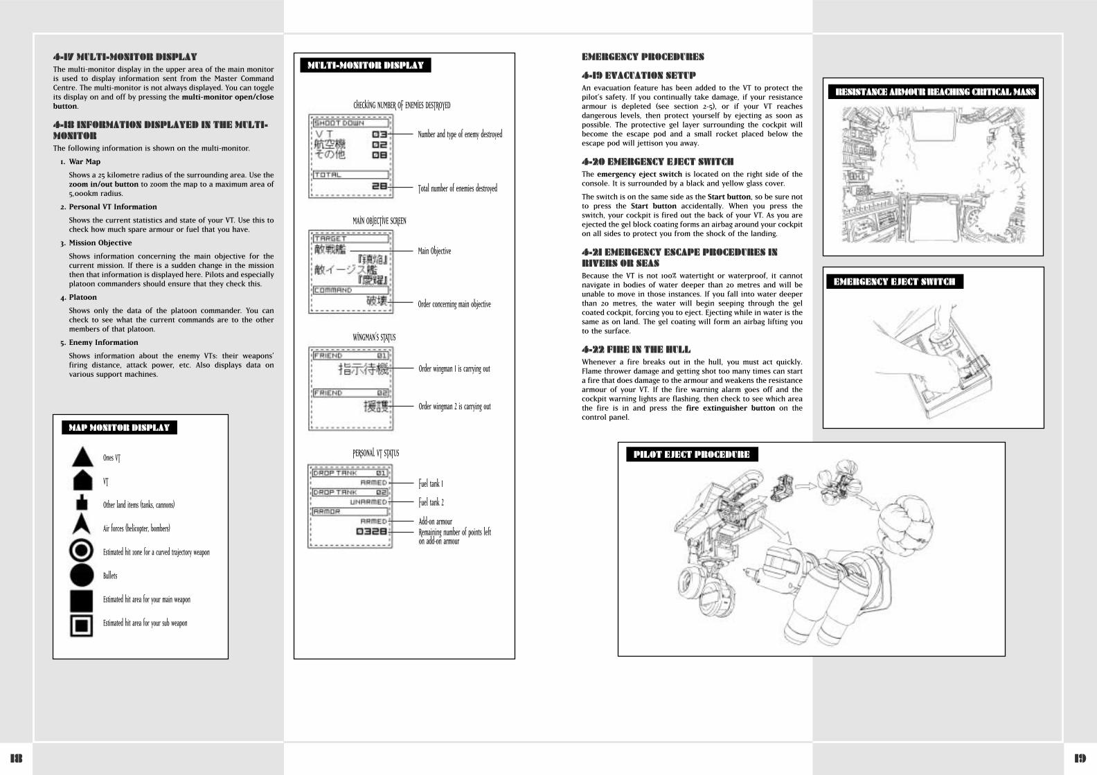
4-17 MULTI-MONITOR DISPLAYThe multi-monitor display in the upper area of the main monitoris used to display information sent from the Master CommandCentre. The multi-monitor is not always displayed. You can toggleits display on and off by pressing the multi-monitor open/closebutton.
4-18 INFORMATION DISPLAYED IN THE MULTI-MONITORThe following information is shown on the multi-monitor.
1. War Map
Shows a 25 kilometre radius of the surrounding area. Use thezoom in/out button to zoom the map to a maximum area of5,000km radius.
2. Personal VT Information
Shows the current statistics and state of your VT. Use this tocheck how much spare armour or fuel that you have.
3. Mission Objective
Shows information concerning the main objective for thecurrent mission. If there is a sudden change in the missionthen that information is displayed here. Pilots and especiallyplatoon commanders should ensure that they check this.
4. Platoon
Shows only the data of the platoon commander. You cancheck to see what the current commands are to the othermembers of that platoon.
5. Enemy Information
Shows information about the enemy VTs: their weapons’firing distance, attack power, etc. Also displays data onvarious support machines.
Ones VT
VT
Other land items (tanks, cannons)
Air forces (helicopter, bombers)
Estimated hit zone for a curved trajectory weapon
Bullets
Estimated hit area for your main weapon
Estimated hit area for your sub weapon
MAP MONITOR DISPLAY
MULTI-MONITOR DISPLAY
CHECKING NUMBER OF ENEMIES DESTROYED
Number and type of enemy destroyed
Total number of enemies destroyed
Main Objective
Order concerning main objective
MAIN OBJECTIVE SCREEN
Order wingman 1 is carrying out
Order wingman 2 is carrying out
WINGMAN’S STATUS
Fuel tank 1
Fuel tank 2
Add-on armourRemaining number of points lefton add-on armour
PERSONAL VT STATUS
EMERGENCY PROCEDURES
4-19 EVACUATION SETUPAn evacuation feature has been added to the VT to protect thepilot’s safety. If you continually take damage, if your resistancearmour is depleted (see section 2-5), or if your VT reachesdangerous levels, then protect yourself by ejecting as soon aspossible. The protective gel layer surrounding the cockpit willbecome the escape pod and a small rocket placed below theescape pod will jettison you away.
4-20 EMERGENCY EJECT SWITCHThe emergency eject switch is located on the right side of theconsole. It is surrounded by a black and yellow glass cover.
The switch is on the same side as the Start button, so be sure notto press the Start button accidentally. When you press theswitch, your cockpit is fired out the back of your VT. As you areejected the gel block coating forms an airbag around your cockpiton all sides to protect you from the shock of the landing.
4-21 EMERGENCY ESCAPE PROCEDURES INRIVERS OR SEASBecause the VT is not 100% watertight or waterproof, it cannotnavigate in bodies of water deeper than 20 metres and will beunable to move in those instances. If you fall into water deeperthan 20 metres, the water will begin seeping through the gelcoated cockpit, forcing you to eject. Ejecting while in water is thesame as on land. The gel coating will form an airbag lifting youto the surface.
4-22 FIRE IN THE HULLWhenever a fire breaks out in the hull, you must act quickly.Flame thrower damage and getting shot too many times can starta fire that does damage to the armour and weakens the resistancearmour of your VT. If the fire warning alarm goes off and thecockpit warning lights are flashing, then check to see which areathe fire is in and press the fire extinguisher button on thecontrol panel.
EMERGENCY EJECT SWITCH
RESISTANCE ARMOUR REACHING CRITICAL MASS
PILOT EJECT PROCEDURE
20 21
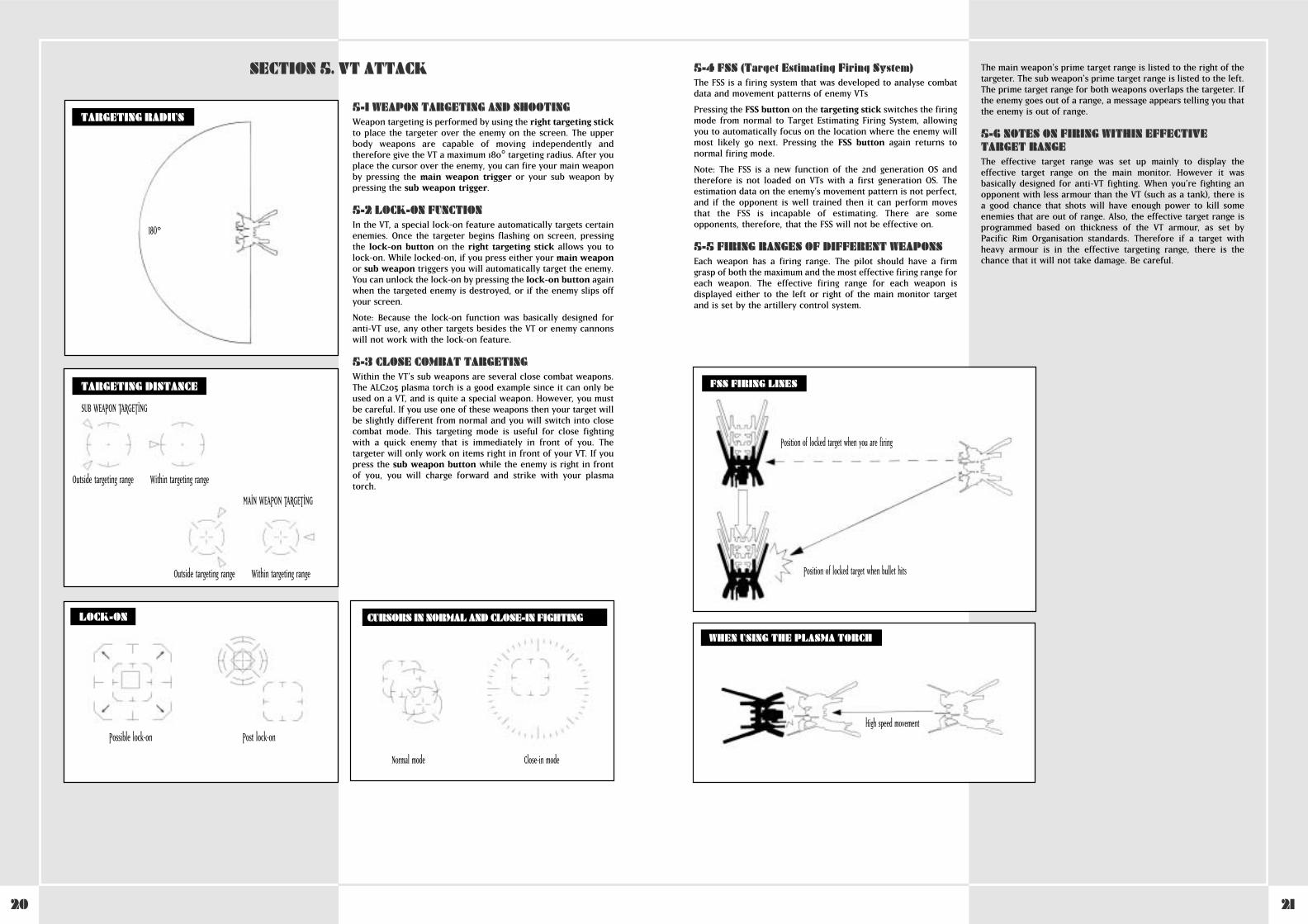
5-1 WEAPON TARGETING AND SHOOTINGWeapon targeting is performed by using the right targeting stickto place the targeter over the enemy on the screen. The upperbody weapons are capable of moving independently andtherefore give the VT a maximum 180° targeting radius. After youplace the cursor over the enemy, you can fire your main weaponby pressing the main weapon trigger or your sub weapon bypressing the sub weapon trigger.
5-2 LOCK-ON FUNCTIONIn the VT, a special lock-on feature automatically targets certainenemies. Once the targeter begins flashing on screen, pressingthe lock-on button on the right targeting stick allows you tolock-on. While locked-on, if you press either your main weaponor sub weapon triggers you will automatically target the enemy.You can unlock the lock-on by pressing the lock-on button againwhen the targeted enemy is destroyed, or if the enemy slips offyour screen.
Note: Because the lock-on function was basically designed foranti-VT use, any other targets besides the VT or enemy cannonswill not work with the lock-on feature.
5-3 CLOSE COMBAT TARGETINGWithin the VT’s sub weapons are several close combat weapons.The ALC205 plasma torch is a good example since it can only beused on a VT, and is quite a special weapon. However, you mustbe careful. If you use one of these weapons then your target willbe slightly different from normal and you will switch into closecombat mode. This targeting mode is useful for close fightingwith a quick enemy that is immediately in front of you. Thetargeter will only work on items right in front of your VT. If youpress the sub weapon button while the enemy is right in frontof you, you will charge forward and strike with your plasmatorch.
SECTION 5. VT ATTACK
TARGETING RADIUS
TARGETING DISTANCE
180°
SUB WEAPON TARGETING
Outside targeting range Within targeting range
MAIN WEAPON TARGETING
Outside targeting range Within targeting range
LOCK-ON
Possible lock-on Post lock-on
CURSORS IN NORMAL AND CLOSE-IN FIGHTING
Normal mode Close-in mode
5-4 FSS (Target Estimating Firing System)The FSS is a firing system that was developed to analyse combatdata and movement patterns of enemy VTs
Pressing the FSS button on the targeting stick switches the firingmode from normal to Target Estimating Firing System, allowingyou to automatically focus on the location where the enemy willmost likely go next. Pressing the FSS button again returns tonormal firing mode.
Note: The FSS is a new function of the 2nd generation OS andtherefore is not loaded on VTs with a first generation OS. Theestimation data on the enemy’s movement pattern is not perfect,and if the opponent is well trained then it can perform movesthat the FSS is incapable of estimating. There are someopponents, therefore, that the FSS will not be effective on.
5-5 FIRING RANGES OF DIFFERENT WEAPONSEach weapon has a firing range. The pilot should have a firmgrasp of both the maximum and the most effective firing range foreach weapon. The effective firing range for each weapon isdisplayed either to the left or right of the main monitor targetand is set by the artillery control system.
The main weapon’s prime target range is listed to the right of thetargeter. The sub weapon’s prime target range is listed to the left.The prime target range for both weapons overlaps the targeter. Ifthe enemy goes out of a range, a message appears telling you thatthe enemy is out of range.
5-6 NOTES ON FIRING WITHIN EFFECTIVETARGET RANGEThe effective target range was set up mainly to display theeffective target range on the main monitor. However it wasbasically designed for anti-VT fighting. When you’re fighting anopponent with less armour than the VT (such as a tank), there isa good chance that shots will have enough power to kill someenemies that are out of range. Also, the effective target range isprogrammed based on thickness of the VT armour, as set byPacific Rim Organisation standards. Therefore if a target withheavy armour is in the effective targeting range, there is thechance that it will not take damage. Be careful.
WHEN USING THE PLASMA TORCH
High speed movement
FSS FIRING LINES
Position of locked target when you are firing
Position of locked target when bullet hits
22 23
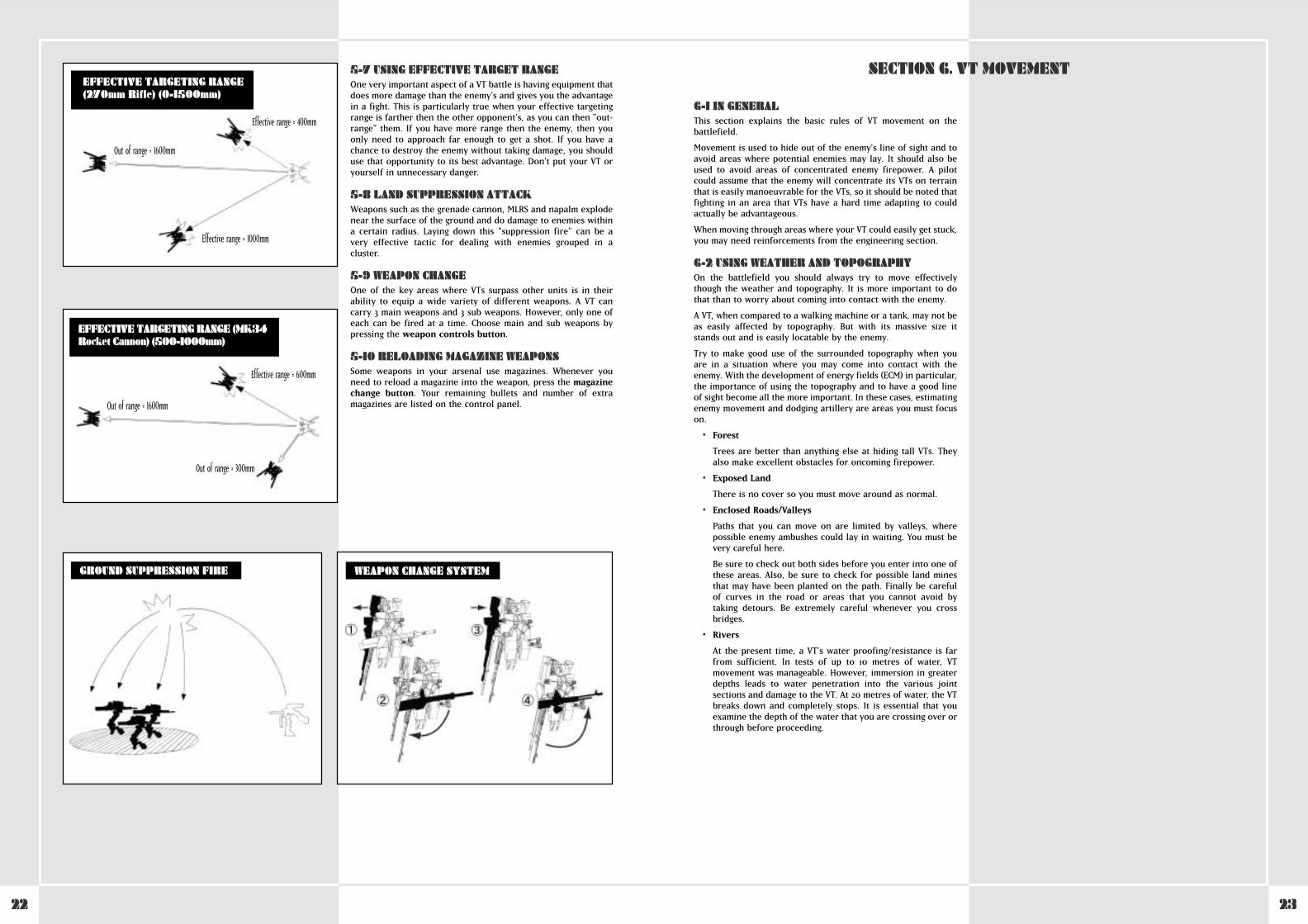
5-7 USING EFFECTIVE TARGET RANGEOne very important aspect of a VT battle is having equipment thatdoes more damage than the enemy’s and gives you the advantagein a fight. This is particularly true when your effective targetingrange is farther then the other opponent’s, as you can then "out-range" them. If you have more range then the enemy, then youonly need to approach far enough to get a shot. If you have achance to destroy the enemy without taking damage, you shoulduse that opportunity to its best advantage. Don’t put your VT oryourself in unnecessary danger.
5-8 LAND SUPPRESSION ATTACKWeapons such as the grenade cannon, MLRS and napalm explodenear the surface of the ground and do damage to enemies withina certain radius. Laying down this "suppression fire" can be avery effective tactic for dealing with enemies grouped in acluster.
5-9 WEAPON CHANGEOne of the key areas where VTs surpass other units is in theirability to equip a wide variety of different weapons. A VT cancarry 3 main weapons and 3 sub weapons. However, only one ofeach can be fired at a time. Choose main and sub weapons bypressing the weapon controls button.
5-10 RELOADING MAGAZINE WEAPONSSome weapons in your arsenal use magazines. Whenever youneed to reload a magazine into the weapon, press the magazinechange button. Your remaining bullets and number of extramagazines are listed on the control panel.
WEAPON CHANGE SYSTEMGROUND SUPPRESSION FIRE
Effective range = 400mm
Effective range = 1000mm
Out of range = 1600mm
EFFECTIVE TARGETING RANGE(270mm Rifle) (0-1500mm)
EFFECTIVE TARGETING RANGE (MK34Rocket Cannon) (500-1000mm)
Effective range = 600mm
Out of range = 1600mm
Out of range = 300mm
6-1 IN GENERALThis section explains the basic rules of VT movement on thebattlefield.
Movement is used to hide out of the enemy’s line of sight and toavoid areas where potential enemies may lay. It should also beused to avoid areas of concentrated enemy firepower. A pilotcould assume that the enemy will concentrate its VTs on terrainthat is easily manoeuvrable for the VTs, so it should be noted thatfighting in an area that VTs have a hard time adapting to couldactually be advantageous.
When moving through areas where your VT could easily get stuck,you may need reinforcements from the engineering section.
6-2 USING WEATHER AND TOPOGRAPHYOn the battlefield you should always try to move effectivelythough the weather and topography. It is more important to dothat than to worry about coming into contact with the enemy.
A VT, when compared to a walking machine or a tank, may not beas easily affected by topography. But with its massive size itstands out and is easily locatable by the enemy.
Try to make good use of the surrounded topography when youare in a situation where you may come into contact with theenemy. With the development of energy fields (ECM) in particular,the importance of using the topography and to have a good lineof sight become all the more important. In these cases, estimatingenemy movement and dodging artillery are areas you must focuson.
• Forest
Trees are better than anything else at hiding tall VTs. Theyalso make excellent obstacles for oncoming firepower.
• Exposed Land
There is no cover so you must move around as normal.
• Enclosed Roads/Valleys
Paths that you can move on are limited by valleys, wherepossible enemy ambushes could lay in waiting. You must bevery careful here.
Be sure to check out both sides before you enter into one ofthese areas. Also, be sure to check for possible land minesthat may have been planted on the path. Finally be carefulof curves in the road or areas that you cannot avoid bytaking detours. Be extremely careful whenever you crossbridges.
• Rivers
At the present time, a VT’s water proofing/resistance is farfrom sufficient. In tests of up to 10 metres of water, VTmovement was manageable. However, immersion in greaterdepths leads to water penetration into the various jointsections and damage to the VT. At 20 metres of water, the VTbreaks down and completely stops. It is essential that youexamine the depth of the water that you are crossing over orthrough before proceeding.
SECTION 6. VT MOVEMENT

2524
STEEL BATTALION CONTROLLER CONFIGURATION

26 27
7-1 ORDERSBasically speaking, battalions and companies give orders toplatoons. Orders are given via written messages, as well asthrough speech. Most commonly, before every mission there willbe a briefing in which some of the following information will bedisplayed:
• Mission objective
• Enemy information
• Friendly units situation
• Topography
• Battlefield state
• Estimated mission completion time
After that, officers of differing rank will help analyse the ordersand you will make a plan of attack for your platoon.
7-2 MISSION ANALYSISOnce you receive a command from one of the high levelcommanders (battalion/company), the platoon divisioncommander will analyse the mission based on key information.The mission analysis includes:
• Mission breakdown
• Enemy information
• Topography
• Weapons that can be used in the current mission
• Necessary equipment and supplies
Before the strategy preparations end, you must request your VTtype and weapons as well as the necessary equipment to take.You should also check your mission objectives again.
You should also make sure that other platoon members arepositively sure of their mission goals, and that they will not makeany mistakes during battle.
7-3 CHOOSING WEAPONSA VT pilot must choose which weapons to take along in battle.These weapons must be appropriate for the mission objectives.You can carry 3 main weapons and 3 sub weapons, but you cannotexceed the maximum weight allowance for your VT type whenchoosing weapons. Note that even if you do not exceed themaximum weight balance for the VT, carrying close to themaximum allowed weight limit is in itself bad for your balancerand can greatly reduce the VT’s performance.
7-4 SELECTION OF ADDITIONAL ARMOUR ANDSUB WEAPONSWhenever you add extra armour onto your VT, you willautomatically be equipped with the sub weapon armouredmissiles. This will reduce the number of selectable sub-weaponsby one. Please make sure that with the armour attached you donot exceed the maximum weight allowance.
7-5 CHOOSING YOUR VTThere are 3 types of VT that are distributed to platoons: Light,Middle, and Heavy. You choose your VT based on the mission butthe actual decision is left to the pilot. Also, when participating inan air drop mission, you can only choose the light type VT.
7-6 ATTACHING EXTRA FUEL TANKS ANDARMOURBased on the mission, you may choose to add extra fuel tanks orarmour. However, additional armour can only be used on alimited number of VTs. Also, be sure that the final total of yourarmour, extra fuel and weapons does not exceed the maximumweight allowance. To learn more about the relationship betweensub weapons and additional armour, read section 7-4.
7-7 SUPPLY REQUESTSBefore you go out to battle, the estimated number of bullets youwill use for that mission will be supplied to you. However, if yourun out of ammo in battle you will quickly need to get more. Inorder to achieve smooth supply transfer you will need to have allpilots estimate the number of extra rounds they think they willuse in battle and send in a supply order form to thereinforcement battalion beforehand.
7-8 FIXED VT FOOD PROVISIONSSince operation time for a VT is rather short, regular foodprovisions are issued from the Provision Company. However,since in some cases food cannot be issued, each VT is loaded withan emergency food supply equivalent to 4 servings. In situationswhere there is no other way, each ranked commander isresponsible for using these. After they are used, an upper levelcommander should be told immediately, so that they can bereplenished.
7-9 BRINGING PERSONAL EFFECTS INTO THECOCKPITThere is a compartment for holding provisions inside the cockpit.If the personal effect is capable of fitting into the compartmentspace then it is possible to bring personal items into the cockpit.However, carrying private items into the VT must be clearedbeforehand by an accompanying commander. Also, it is forbiddento carry the operation manual, which is strictly confidential, intothe VT.
SECTION 7. PLATOON STRATEGY PREPARATIONS
8-1 SUMMARYCommunications has the important role of helping relate keyinformation, changing plans within groups, helping carry outimportant orders, and assisting in the transfer of new orders andinformation.
Every VT has a JARC-F522 radio for communications.
In the platoon commander’s VT there are 2 JARC-F522 radios or 1JARC-F522 radio and 1 JARC-A232 radio. Try to pronounce clearlywhen speaking over the radio and keep the conversation to thepoint. Also, be careful of enemy listening devices and keep youridentity secret by using call signs whilst talking.
8-2 PRESET CHANNELSSome channels are preset in the standard VT radio. This saves thetime it would take to tune into each of these channels, time thatyou may not have in the heat of battle. You can have up to 5preset channels for you VT radio.
8-3 RADIO COMMUNICATION PROCEDURESCommunication via the radio is carried out by selecting channelsusing an antenna. Then press the communication button tobegin the transmission. Communication is fixed to 3 possiblechoices. You cannot change what each of these choice buttonsdoes. The choices are as follows:
• Communication button 1 – Respond/call
• Communication button 2 – Repeat
• Communication button 3 – Supply request
SECTION 8. RADIO TRANSMISSIONS
1. Communication panel 1 (from the main battalion Argus) begins to flash.This signals that a message from the main battalion is coming in.
2. Set the tuner on Communications Panel 1.
3. Press Communication Button 1 (respond/call) and open a connection.
"This is Oscar 3. Argus, go ahead."
The battalion head gives his message.
"This is Argus. Your division is in a bad spot! Disengage immediately!"
5. After you hear what was said, press Communication Button 1(respond/call).
"Oscar 3. I copy that."
6. Finish the communication.
7. If you didn’t hear the message, press Communication Button 2 (repeat).
COMMUNICATIONS PROCEDURES(example: order to retreat)
COCKPIT: MAIN BATTALION COMMAND ROOM:
1. Communication panel 1 (from the main battalion Argus) begins to flash.This signals that a message from the main battalion is coming in.
2. Set the tuner on Communications Panel 1.
3. Press Communication Button 1 (respond/call) and open a connection.
"This is Oscar 3. Argus, go ahead."
4. The battalion head gives his message.
"This is Argus. Your division is in a bad spot! Retreat immediately!"
5. After you hear what was said, press Communication Button 1 "
6. If you didn’t hear the message, press Communication Button 2 (repeat).
7. Finish the communication.
Communication panel 1 (from the main battalion Argus) begins to flash.This signals that a message from the main battalion is coming in.
Set the tuner on Communications Panel 1.
Press Communication Button 1 (respond/call) and open a connection.
"This is Oscar 3. Argus, go ahead."
4. The battalion head gives his message.
"This is Argus. Your division is in a bad spot! Retreat immediately!"
After you hear what was said, press Communication Button 1 (respond/call).
"Oscar 3. I copy that."
If you did not hear the message, press Communication Button 2 (repeat).
Finish the communication.

2928
COMMUNICATIONS PANEL CHANNEL SETTINGS
Comm Panel 1 Comm Panel 2 Comm Panel 3 Comm Panel 4 Comm Panel 5MIS00MIS01MIS02MIS03 Command Supply VT CommanderMIS04 Command Supply VT CommanderMIS05 Command Supply VT CommanderMIS06 Command Supply VT CommanderMIS07 Command Supply VT CommanderMIS08 Command Supply VT CommanderMIS09 Command Supply VT CommanderMIS10 Command Supply VT CommanderMIS11 Command Supply VT CommanderMIS12 Command Supply Wingman 1 Wingman 2 Wingman 1/2MIS13 Command Supply Wingman 1 Wingman 2 Wingman 1/2MIS14 Command Supply Wingman 1 Wingman 2 Wingman 1/2MIS15 Command Supply Wingman 1 Wingman 2 Wingman 1/2MIS16 Command Supply Wingman 1 Wingman 2 Wingman 1/2MIS17 Command Supply Spy DivisionMIS18 Command Supply Wingman 1 Wingman 2 Wingman 1/2MIS19 Command Supply Wingman 1 Wingman 2 Wingman 1/2MIS20 Command SupplyMIS21 Command Supply Wingman 1 Wingman 2 Wingman 1/2MIS22 Command Supply Wingman 1 Wingman 2 Wingman 1/2MIS23 Command Supply Wingman 1 Wingman 2 Wingman 1/2
8-4 SENDING A MESSAGE1. Choose the person you will call by dialling their
channel on the tuner.
2. Press communication button 1 (call/respond)to place the call.
3. The person you are calling will respond.
4. After making sure this is the correct person,state your request.
5. The other person will check your request.
6. The call will end.
8-5 RECEIVING A MESSAGE1. When a message comes in, your communication
panel will begin to flash. Turn the tuner to theflashing channel. By doing this you can hear theother person’s message.
2. Press communication button 1 (call/respond)and respond to the message.
3. The other person will see that you respondedand state the message.
4. After you hear the message, presscommunication button 1 (call/respond) tofinish the call.
8-6 REPEATING THE MESSAGEIf you did not catch what someone said in theircommunication, press communication button 2 torequest that the person repeat the message. You canmake a request any time the communication panel isflashing (indicating that the lines are open). Onceyou press communication button 1, thecommunication will end and the line will be closed.
CALL SIGN LIST (printed 2080)Group Call Sign English Name Formal NamePlayer(Platoon) Oscar 3 Oscar 3 7th Special Panzer Division, 34th Special Armoured Battalion, 6th Special Armoured Company, 1st Platoon 3rd VTCommander Oscar 1 Oscar 1 7th Special Panzer Division, 34th Special Armoured Battalion, 6th Special Armoured Company, 1st Platoon 1st VTMain Battalion Argus Argus 7th Special Panzer Division, 34th Special Armoured Main BattalionSupply Wagonmaster Wagonmaster 7th Special Panzer Division, Reinforcement Supply Battalion
CALL SIGN LIST (printed 2082)Player(Platoon) Xray 1 Xray 1 7th Special Panzer Division, 34th Special Armoured Battalion, 6th Special Armoured Company, 1st Platoon 1st VTWingman 1 Xray 2 Xray 2 7th Special Panzer Division, 34th Special Armoured Battalion, 6th Special Armoured Company, 1st Platoon 2nd VTWingman 2 Xray 3 Xray 3 7th Special Panzer Division, 34th Special Armoured Battalion, 6th Special Armoured Company, 1st Platoon 3rd VTMain Battalion Argus Argus 7th Special Panzer Division, 34th Special Armoured Main BattalionSupply Wagonmaster Wagonmaster 7th Special Panzer Division, Reinforcement Supply BattalionSpy Blackwidow Blackwidow ??????????
COMMUNICATION BUTTONS (2082)Comm Button 1 Comm Button 2 Comm Button 3 Comm Button 4 Comm Button 5Call/Respond Repeat Supply Request
COMMUNICATION BUTTONS (2080)Comm Button 1 Comm Button 2 Comm Button 3 Comm Button 4 Comm Button 5Call/Respond Repeat Supply Request Backup Request
9-1 ACCEPTING SUPPLIESSupplies are necessary for maintaining the power of the VT. Finda location where you can re-supply yourself in battle. Re-supplying during a battle is a regular and arduous task. During abattle, try receiving supplies only when you have some cover orlate at night. Supplies for VTs are carried out via a supplyhelicopter under the Supply Battalion of the ReinforcementsDivision. Not only can you refuel and replenish your bullets, butthe supply helicopter can also bring new armour, additionalarmour, and replacement parts for your VT. For smoothsupplying, be sure to issue your estimated supply request beforegoing out on your mission.
9-2 CLASSIFYING SUPPLIESIn order to make the issuing of supplies an easier task, they havebeen separated into 5 major groups. With a few exceptions, themajority of parts you will request before a battle will fit into thefollowing 3 groups.
These are issued as one order to each VT.
1. Type 1 supplies: Foodstuffs
2. Type 3 supplies: Liquids (oil, fuel, lubricant)
3. Type 5 supplies: Various bullets
Before going out to battle, each pilot must create a list of thenecessary supplies and get it approved by his commandingofficer.
9-3 SUPPLY VIA SUPPLY HELICOPTERDuring battle, supplies to VTs are brought in via a supplyhelicopter that operates under the Division Supply Battalion.When you request supplies, the helicopter heads to the VTlocation. Once it arrives, it begins to hover. The pilot must movethe VT below the helicopter. Then the transference of fuel andbullets occurs. You can also transfer new armour andreplacement parts for your VT.
9-4 CHOICES AND CAUTIONS WHEN RECEIVINGSUPPLIESSince it takes time to re-supply, there is a temporary amount oftime when both your VT and the supply helicopter are open toattack. In order to prevent attack you must examine thesurroundings and be cautious of your environment. Try to set there-supply location at a site that has some cover and few visibleenemies. This is an important measure in preventing thehelicopter from being shot down before it can re-supply you.
9-5 OPENING OF SUPPLY ISSUANCE CENTRESometimes due to battle circumstances or weather problems, thesupply helicopter cannot come to re-supply. In order to solvethese situations, a supply issuance centre has been set up behindfriendly force lines. The location of the supply issuance centre isdetermined before a battle, and is set up using these guidelines:
1. It has an adequate amount of space to store necessarysupplies.
2. A favourable path connects the front lines with the backlines.
3. It is hidden from enemy vision.
4. It has coverage from enemy firepower.
The Supply Issuance Centre is only set up in locations where thefront line has been fixed and there is an encampment coveringthe area. Basically, it is a unique exception.
As a basic VT duty, you are expected to refuel using the supplyhelicopter whenever possible.
SECTION 9. SUPPLY
VT HELICOPTER SUPPLY DIAGRAM
Normal flight
Re-supply is possible
3130
10-1 LEADERSHIP DUTIESA commander’s duty is to issue orders to his troops and fulfil hisdesignated mission. Commanders earn trust from their troopsthrough solid leadership and maintaining a strong, stabledivision. Through this, they can increase their VT ability andskills.
10-2 NECESSARY QUALITIES FOR ACOMMANDERA commander has the responsibility to carry out his mission andis responsible for his troops. A commander must have a goodknowledge of his troops, equipment, tactics, and strategy whilealso being a top-notch VT pilot. However, the most importantresponsibility of a commander is to earn his troops’ trust, providethem with a role model, and proceed forward though his mission.He must work to break though tough situations. In battle he mustmaintain a strong will and sharp judgment. He must be quick anddecisive. If the commander hesitates in battle then his troopsbecome scared and lose their confidence. Because of this he mustcarefully analyse the mission he has been assigned and be able toplan independently.
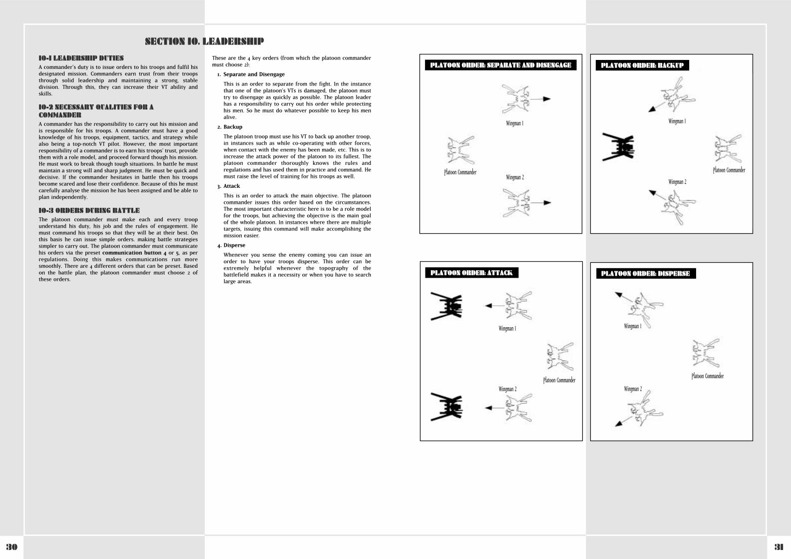
10-3 ORDERS DURING BATTLEThe platoon commander must make each and every troopunderstand his duty, his job and the rules of engagement. Hemust command his troops so that they will be at their best. Onthis basis he can issue simple orders. making battle strategiessimpler to carry out. The platoon commander must communicatehis orders via the preset communication button 4 or 5, as perregulations. Doing this makes communications run moresmoothly. There are 4 different orders that can be preset. Basedon the battle plan, the platoon commander must choose 2 ofthese orders.
These are the 4 key orders (from which the platoon commandermust choose 2):
1. Separate and Disengage
This is an order to separate from the fight. In the instancethat one of the platoon’s VTs is damaged, the platoon musttry to disengage as quickly as possible. The platoon leaderhas a responsibility to carry out his order while protectinghis men. So he must do whatever possible to keep his menalive.
2. Backup
The platoon troop must use his VT to back up another troop,in instances such as while co-operating with other forces,when contact with the enemy has been made, etc. This is toincrease the attack power of the platoon to its fullest. Theplatoon commander thoroughly knows the rules andregulations and has used them in practice and command. Hemust raise the level of training for his troops as well.
3. Attack
This is an order to attack the main objective. The platooncommander issues this order based on the circumstances.The most important characteristic here is to be a role modelfor the troops, but achieving the objective is the main goalof the whole platoon. In instances where there are multipletargets, issuing this command will make accomplishing themission easier.
4. Disperse
Whenever you sense the enemy coming you can issue anorder to have your troops disperse. This order can beextremely helpful whenever the topography of thebattlefield makes it a necessity or when you have to searchlarge areas.
WHEN USING THE PLASMA TORCH
SECTION 10. LEADERSHIP
PLATOON ORDER: SEPARATE AND DISENGAGE PLATOON ORDER: BACKUP
PLATOON ORDER: ATTACK PLATOON ORDER: DISPERSE
Wingman 1
Wingman 2Platoon Commander
Wingman 1
Wingman 2
Platoon Commander
Wingman 1
Wingman 2Platoon Commander
Wingman 1
Wingman 2
Platoon Commander
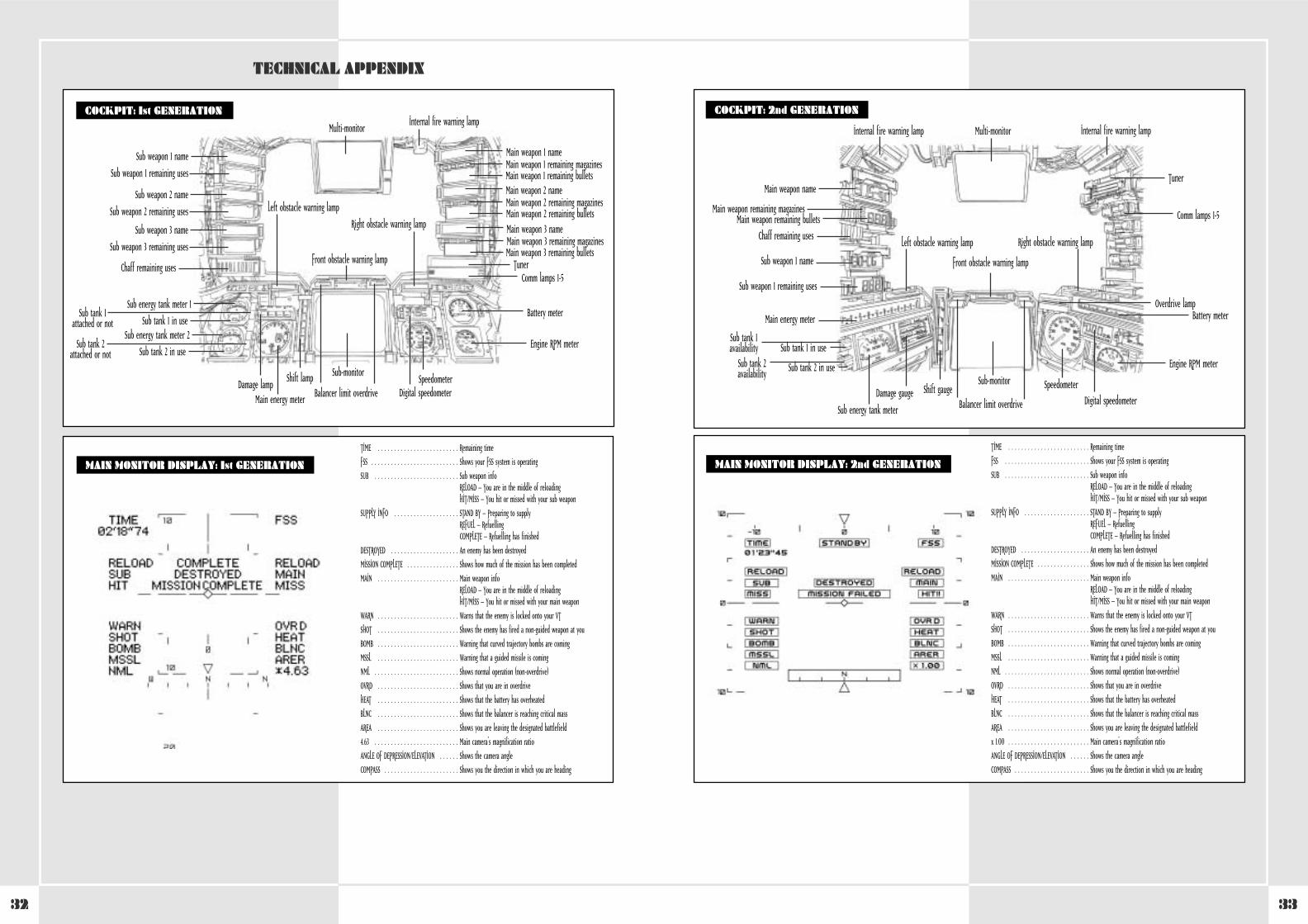
3332
WHEN USING THE PLASMA TORCH
TECHNICAL APPENDIX
COCKPIT: 1st GENERATION
Front obstacle warning lamp
Multi-monitor
Sub weapon 1 name
Sub weapon 1 remaining uses
Main weapon 1 nameMain weapon 1 remaining magazinesMain weapon 1 remaining bullets
Internal fire warning lamp
Right obstacle warning lamp
Left obstacle warning lamp
Main weapon 2 nameMain weapon 2 remaining magazinesMain weapon 2 remaining bulletsMain weapon 3 nameMain weapon 3 remaining magazinesMain weapon 3 remaining bullets
Comm lamps 1-5
Battery meter
Engine RPM meter
Speedometer
Main energy meterDamage lamp
Sub-monitorShift lampDigital speedometerBalancer limit overdrive
Tuner
Sub weapon 2 name
Sub weapon 2 remaining uses
Sub energy tank meter 1Sub tank 1
attached or not Sub tank 1 in useSub energy tank meter 2
Sub tank 2attached or not Sub tank 2 in use
Sub weapon 3 name
Sub weapon 3 remaining uses
Chaff remaining uses
WHEN USING THE PLASMA TORCHCOCKPIT: 2nd GENERATION
Front obstacle warning lamp
Balancer limit overdrive
Multi-monitor
Main weapon name
Main weapon remaining magazinesMain weapon remaining bullets
Internal fire warning lamp Internal fire warning lamp
Right obstacle warning lampLeft obstacle warning lamp
Comm lamps 1-5
Battery meterOverdrive lamp
Engine RPM meter
Speedometer
Main energy meter
Damage gaugeSub-monitor
Shift gaugeDigital speedometer
Tuner
Sub weapon 1 name
Sub weapon 1 remaining uses
Sub energy tank meter
Sub tank 1 in useSub tank 1availability
Sub tank 2 in useSub tank 2availability
Chaff remaining uses
MAIN MONITOR DISPLAY: 2nd GENERATION
TIME . . . . . . . . . . . . . . . . . . . . . . . . . Remaining time
FSS . . . . . . . . . . . . . . . . . . . . . . . . . . Shows your FSS system is operating
SUB . . . . . . . . . . . . . . . . . . . . . . . . . . Sub weapon infoRELOAD – You are in the middle of reloadingHIT/MISS – You hit or missed with your sub weapon
SUPPLY INFO . . . . . . . . . . . . . . . . . . . . STAND BY – Preparing to supplyREFUEL – RefuellingCOMPLETE – Refuelling has finished
DESTROYED . . . . . . . . . . . . . . . . . . . . . An enemy has been destroyed
MISSION COMPLETE . . . . . . . . . . . . . . . . Shows how much of the mission has been completed
MAIN . . . . . . . . . . . . . . . . . . . . . . . . . Main weapon infoRELOAD – You are in the middle of reloadingHIT/MISS – You hit or missed with your main weapon
WARN . . . . . . . . . . . . . . . . . . . . . . . . . Warns that the enemy is locked onto your VT
SHOT . . . . . . . . . . . . . . . . . . . . . . . . . Shows the enemy has fired a non-guided weapon at you
BOMB . . . . . . . . . . . . . . . . . . . . . . . . . Warning that curved trajectory bombs are coming
MSSL . . . . . . . . . . . . . . . . . . . . . . . . . Warning that a guided missile is coming
NML . . . . . . . . . . . . . . . . . . . . . . . . . . Shows normal operation (non-overdrive)
OVRD . . . . . . . . . . . . . . . . . . . . . . . . . Shows that you are in overdrive
HEAT . . . . . . . . . . . . . . . . . . . . . . . . . Shows that the battery has overheated
BLNC . . . . . . . . . . . . . . . . . . . . . . . . . Shows that the balancer is reaching critical mass
AREA . . . . . . . . . . . . . . . . . . . . . . . . . Shows you are leaving the designated battlefield
x 1.00 . . . . . . . . . . . . . . . . . . . . . . . . . Main camera’s magnification ratio
ANGLE OF DEPRESSION/ELEVATION . . . . . . Shows the camera angle
COMPASS . . . . . . . . . . . . . . . . . . . . . . . Shows you the direction in which you are heading
MAIN MONITOR DISPLAY: 1st GENERATION
TIME . . . . . . . . . . . . . . . . . . . . . . . . . Remaining time
FSS . . . . . . . . . . . . . . . . . . . . . . . . . . . Shows your FSS system is operating
SUB . . . . . . . . . . . . . . . . . . . . . . . . . . Sub weapon infoRELOAD – You are in the middle of reloadingHIT/MISS – You hit or missed with your sub weapon
SUPPLY INFO . . . . . . . . . . . . . . . . . . . . STAND BY – Preparing to supplyREFUEL – RefuellingCOMPLETE – Refuelling has finished
DESTROYED . . . . . . . . . . . . . . . . . . . . . An enemy has been destroyed
MISSION COMPLETE . . . . . . . . . . . . . . . . Shows how much of the mission has been completed
MAIN . . . . . . . . . . . . . . . . . . . . . . . . . Main weapon infoRELOAD – You are in the middle of reloadingHIT/MISS – You hit or missed with your main weapon
WARN . . . . . . . . . . . . . . . . . . . . . . . . . Warns that the enemy is locked onto your VT
SHOT . . . . . . . . . . . . . . . . . . . . . . . . . Shows the enemy has fired a non-guided weapon at you
BOMB . . . . . . . . . . . . . . . . . . . . . . . . . Warning that curved trajectory bombs are coming
MSSL . . . . . . . . . . . . . . . . . . . . . . . . . Warning that a guided missile is coming
NML . . . . . . . . . . . . . . . . . . . . . . . . . . Shows normal operation (non-overdrive)
OVRD . . . . . . . . . . . . . . . . . . . . . . . . . Shows that you are in overdrive
HEAT . . . . . . . . . . . . . . . . . . . . . . . . . Shows that the battery has overheated
BLNC . . . . . . . . . . . . . . . . . . . . . . . . . Shows that the balancer is reaching critical mass
AREA . . . . . . . . . . . . . . . . . . . . . . . . . Shows you are leaving the designated battlefield
4.63 . . . . . . . . . . . . . . . . . . . . . . . . . . Main camera’s magnification ratio
ANGLE OF DEPRESSION/ELEVATION . . . . . . Shows the camera angle
COMPASS . . . . . . . . . . . . . . . . . . . . . . . Shows you the direction in which you are heading
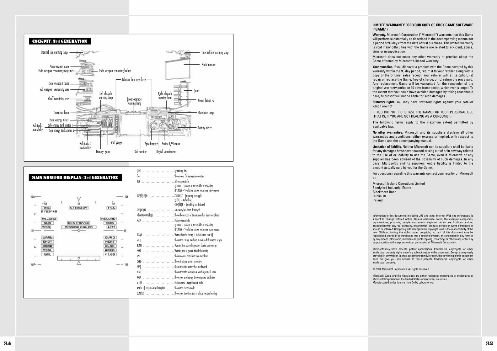
34
LIMITED WARRANTY FOR YOUR COPY OF XBOX GAME SOFTWARE(“GAME”)Warranty. Microsoft Corporation (“Microsoft”) warrants that this Gamewill perform substantially as described in the accompanying manual fora period of 90 days from the date of first purchase. This limited warrantyis void if any difficulties with the Game are related to accident, abuse,virus or misapplication.Microsoft does not make any other warranty or promise about theGame affected by Microsoft’s limited warranty.
Your remedies. If you discover a problem with the Game covered by thiswarranty within the 90 day period, return it to your retailer along with acopy of the original sales receipt. Your retailer will, at its option, (a)repair or replace the Game, free of charge, or (b) return the price paid.Any replacement Game will be warranted for the remainder of theoriginal warranty period or 30 days from receipt, whichever is longer. Tothe extent that you could have avoided damages by taking reasonablecare, Microsoft will not be liable for such damages.
Statutory rights. You may have statutory rights against your retailerwhich are not
IF YOU DID NOT PURCHASE THE GAME FOR YOUR PERSONAL USE(THAT IS, IF YOU ARE NOT DEALING AS A CONSUMER)
The following terms apply to the maximum extent permitted byapplicable law.
No other warranties. Microsoft and its suppliers disclaim all otherwarranties and conditions, either express or implied, with respect tothe Game and the accompanying manual.
Limitation of liability. Neither Microsoft nor its suppliers shall be liablefor any damages howsoever caused arising out of or in any way relatedto the use of or inability to use the Game, even if Microsoft or anysupplier has been advised of the possibility of such damages. In anycase, Microsoft’s and its suppliers’ entire liability is limited to theamount actually paid by you for the Game.
For questions regarding this warranty contact your retailer or Microsoftat:
Microsoft Ireland Operations LimitedSandyford Industrial EstateBlackthorn RoadDublin 18Ireland
Information in this document, including URL and other Internet Web site references, issubject to change without notice. Unless otherwise noted, the example companies,organizations, products, people and events depicted herein are fictitious and noassociation with any real company, organization, product, person or event is intended orshould be inferred. Complying with all applicable copyright laws is the responsibility of theuser. Without limiting the rights under copyright, no part of this document may bereproduced, stored in or introduced into a retrieval system, or transmitted in any form orby any means (electronic, mechanical, photocopying, recording, or otherwise), or for anypurpose, without the express written permission of Microsoft Corporation.
Microsoft may have patents, patent applications, trademarks, copyrights, or otherintellectual property rights covering subject matter in this document. Except as expresslyprovided in any written license agreement from Microsoft, the furnishing of this documentdoes not give you any license to these patents, trademarks, copyrights, or otherintellectual property.
© 2003, Microsoft Corporation. All rights reserved.
Microsoft, Xbox, and the Xbox logos are either registered trademarks or trademarks ofMicrosoft Corporation in the United States and/or other countries.Manufactured under license from Dolby Laboratories.
WHEN USING THE PLASMA TORCHCOCKPIT: 3rd GENERATION
Front obstaclewarning lamp
Balancer limit overdrive
Multi-monitorMain weapon nameMain weapon remaining magazines Main weapon remaining bullets
Internal fire warning lamp Internal fire warning lamp
Right obstaclewarning lamp
Left obstaclewarning lamp
Comm lamps 1-5
Battery meter
Overdrive lampOverdrive lamp
Engine RPM meterSpeedometer
Main energy meter
Damage gauge Sub-monitor
Shift gauge
Digital speedometer
Tuner
Sub weapon 1 nameSub weapon 1 remaining uses
Sub energy tank meter 1Sub tank 1availability Sub energy tank meter 2
Sub tank 2availability
Chaff remaining uses
MAIN MONITOR DISPLAY: 3rd GENERATION
TIME . . . . . . . . . . . . . . . . . . . . . . . . . Remaining time
FSS . . . . . . . . . . . . . . . . . . . . . . . . . . . Shows your FSS system is operating
SUB . . . . . . . . . . . . . . . . . . . . . . . . . . Sub weapon infoRELOAD – You are in the middle of reloadingHIT/MISS – You hit or missed with your sub weapon
SUPPLY INFO . . . . . . . . . . . . . . . . . . . . STAND BY – Preparing to supplyREFUEL – RefuellingCOMPLETE – Refuelling has finished
DESTROYED . . . . . . . . . . . . . . . . . . . . . An enemy has been destroyed
MISSION COMPLETE . . . . . . . . . . . . . . . . Shows how much of the mission has been completed
MAIN . . . . . . . . . . . . . . . . . . . . . . . . . Main weapon infoRELOAD – You are in the middle of reloadingHIT/MISS – You hit or missed with your main weapon
WARN . . . . . . . . . . . . . . . . . . . . . . . . . Warns that the enemy is locked onto your VT
SHOT . . . . . . . . . . . . . . . . . . . . . . . . . Shows the enemy has fired a non-guided weapon at you
BOMB . . . . . . . . . . . . . . . . . . . . . . . . . Warning that curved trajectory bombs are coming
MSSL . . . . . . . . . . . . . . . . . . . . . . . . . Warning that a guided missile is coming
NML . . . . . . . . . . . . . . . . . . . . . . . . . . Shows normal operation (non-overdrive)
OVRD . . . . . . . . . . . . . . . . . . . . . . . . . Shows that you are in overdrive
HEAT . . . . . . . . . . . . . . . . . . . . . . . . . Shows that the battery has overheated
BLNC . . . . . . . . . . . . . . . . . . . . . . . . . Shows that the balancer is reaching critical mass
AREA . . . . . . . . . . . . . . . . . . . . . . . . . Shows you are leaving the designated battlefield
x 1.00 . . . . . . . . . . . . . . . . . . . . . . . . . Main camera’s magnification ratio
ANGLE OF DEPRESSION/ELEVATION . . . . . . Shows the camera angle
COMPASS . . . . . . . . . . . . . . . . . . . . . . . Shows you the direction in which you are heading
35
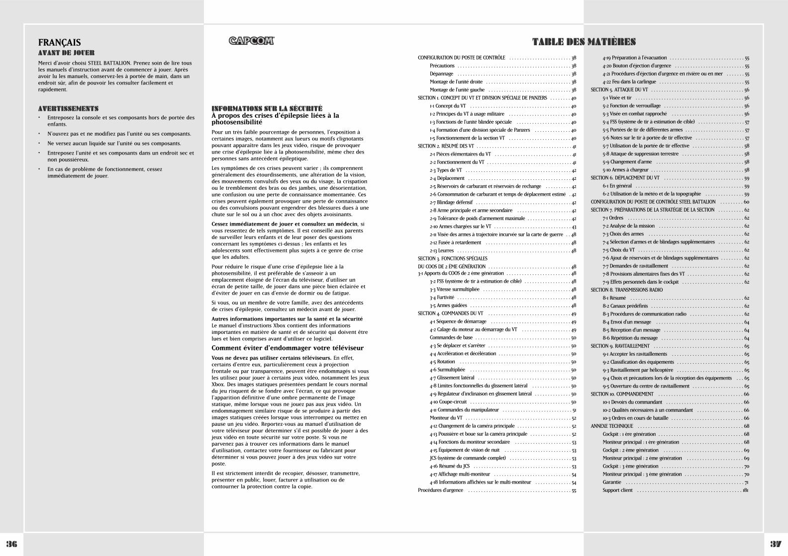
3736
CONFIGURATION DU POSTE DE CONTRÔLE . . . . . . . . . . . . . . . . . . . . . . . . 38
Précautions . . . . . . . . . . . . . . . . . . . . . . . . . . . . . . . . . . . . . . . . . . . . 38
Dépannage . . . . . . . . . . . . . . . . . . . . . . . . . . . . . . . . . . . . . . . . . . . . 38
Montage de l'unité droite . . . . . . . . . . . . . . . . . . . . . . . . . . . . . . . . . 38
Montage de l'unité gauche . . . . . . . . . . . . . . . . . . . . . . . . . . . . . . . . 38
SECTION 1. CONCEPT DU VT ET DIVISION SPÉCIALE DE PANZERS . . . . . . . . 40
1-1 Concept du VT . . . . . . . . . . . . . . . . . . . . . . . . . . . . . . . . . . . . . . . 40
1-2 Principes du VT à usage militaire . . . . . . . . . . . . . . . . . . . . . . . . 40
1-3 Fonctions de l'unité blindée spéciale . . . . . . . . . . . . . . . . . . . . . 40
1-4 Formation d'une division spéciale de Panzers . . . . . . . . . . . . . . 40
1-5 Fonctionnement de la section VT . . . . . . . . . . . . . . . . . . . . . . . . 40
SECTION 2. RÉSUMÉ DES VT . . . . . . . . . . . . . . . . . . . . . . . . . . . . . . . . . . . . . 41
2-1 Pièces élémentaires du VT . . . . . . . . . . . . . . . . . . . . . . . . . . . . . . 41
2-2 Fonctionnement du VT . . . . . . . . . . . . . . . . . . . . . . . . . . . . . . . . . 41
2-3 Types de VT . . . . . . . . . . . . . . . . . . . . . . . . . . . . . . . . . . . . . . . . . 42
2-4 Déplacement . . . . . . . . . . . . . . . . . . . . . . . . . . . . . . . . . . . . . . . . 42
2-5 Réservoirs de carburant et réservoirs de rechange . . . . . . . . . . 42
2-6 Consommation de carburant et temps de déplacement estimé . 42
2-7 Blindage défensif . . . . . . . . . . . . . . . . . . . . . . . . . . . . . . . . . . . . . 42
2-8 Arme principale et arme secondaire . . . . . . . . . . . . . . . . . . . . . 42
2-9 Tolérance de poids d'armement maximale . . . . . . . . . . . . . . . . . 42
2-10 Armes chargées sur le VT . . . . . . . . . . . . . . . . . . . . . . . . . . . . . . 43
2-11 Visée des armes à trajectoire incurvée sur la carte de guerre . . 48
2-12 Fusée à retardement . . . . . . . . . . . . . . . . . . . . . . . . . . . . . . . . . 48
2-13 Leurres . . . . . . . . . . . . . . . . . . . . . . . . . . . . . . . . . . . . . . . . . . . . 48
SECTION 3. FONCTIONS SPÉCIALES
DU COOS DE 2 ÈME GÉNÉRATION . . . . . . . . . . . . . . . . . . . . . . . . . . . . . . . . 483-1 Apports du COOS de 2 ème génération . . . . . . . . . . . . . . . . . . . . . . . . . 48
3-2 FSS (système de tir à estimation de cible) . . . . . . . . . . . . . . . . . . 48
3-3 Vitesse surmultipliée . . . . . . . . . . . . . . . . . . . . . . . . . . . . . . . . . . 48
3-4 Furtivité . . . . . . . . . . . . . . . . . . . . . . . . . . . . . . . . . . . . . . . . . . . . 48
3-5 Armes guidées . . . . . . . . . . . . . . . . . . . . . . . . . . . . . . . . . . . . . . . 48
SECTION 4. COMMANDES DU VT . . . . . . . . . . . . . . . . . . . . . . . . . . . . . . . . 49
4-1 Séquence de démarrage . . . . . . . . . . . . . . . . . . . . . . . . . . . . . . . 49
4-2 Calage du moteur au démarrage du VT . . . . . . . . . . . . . . . . . . . 49
Commandes de base . . . . . . . . . . . . . . . . . . . . . . . . . . . . . . . . . . . . . 50
4-3 Se déplacer et s'arrêter . . . . . . . . . . . . . . . . . . . . . . . . . . . . . . . . 50
4-4 Accélération et décélération . . . . . . . . . . . . . . . . . . . . . . . . . . . . 50
4-5 Rotation . . . . . . . . . . . . . . . . . . . . . . . . . . . . . . . . . . . . . . . . . . . 50
4-6 Surmultipliée . . . . . . . . . . . . . . . . . . . . . . . . . . . . . . . . . . . . . . . 50
4-7 Glissement latéral . . . . . . . . . . . . . . . . . . . . . . . . . . . . . . . . . . . . 50
4-8 Limites fonctionnelles du glissement latéral . . . . . . . . . . . . . . . 50
4-9 Régulateur d'inclinaison en glissement latéral . . . . . . . . . . . . . . 50
4-10 Coupe-circuit . . . . . . . . . . . . . . . . . . . . . . . . . . . . . . . . . . . . . . . 50
4-11 Commandes du manipulateur . . . . . . . . . . . . . . . . . . . . . . . . . . . 51
Moniteur du VT . . . . . . . . . . . . . . . . . . . . . . . . . . . . . . . . . . . . . . . . . 52
4-12 Changement de la caméra principale . . . . . . . . . . . . . . . . . . . . . 52
4-13 Poussière et boue sur la caméra principale . . . . . . . . . . . . . . . . 52
4-14 Fonctions du moniteur secondaire . . . . . . . . . . . . . . . . . . . . . . 53
4-15 Équipement de vision de nuit . . . . . . . . . . . . . . . . . . . . . . . . . . 53
JCS (système de commande complet) . . . . . . . . . . . . . . . . . . . . . . . . 53
4-16 Résumé du JCS . . . . . . . . . . . . . . . . . . . . . . . . . . . . . . . . . . . . . . 53
4-17 Affichage multi-moniteur . . . . . . . . . . . . . . . . . . . . . . . . . . . . . . 54
4-18 Informations affichées sur le multi-moniteur . . . . . . . . . . . . . . 54
Procédures d'urgence . . . . . . . . . . . . . . . . . . . . . . . . . . . . . . . . . . . . . . . . 55
4-19 Préparation à l'évacuation . . . . . . . . . . . . . . . . . . . . . . . . . . . . . 55
4-20 Bouton d'éjection d'urgence . . . . . . . . . . . . . . . . . . . . . . . . . . . 55
4-21 Procédures d'éjection d'urgence en rivière ou en mer . . . . . . . 55
4-22 Feu dans la carlingue . . . . . . . . . . . . . . . . . . . . . . . . . . . . . . . . . 55
SECTION 5. ATTAQUE DU VT . . . . . . . . . . . . . . . . . . . . . . . . . . . . . . . . . . . . 56
5-1 Visée et tir . . . . . . . . . . . . . . . . . . . . . . . . . . . . . . . . . . . . . . . . . . 56
5-2 Fonction de verrouillage . . . . . . . . . . . . . . . . . . . . . . . . . . . . . . . 56
5-3 Visée en combat rapproché . . . . . . . . . . . . . . . . . . . . . . . . . . . . 56
5-4 FSS (système de tir à estimation de cible) . . . . . . . . . . . . . . . . . . 57
5-5 Portées de tir de différentes armes . . . . . . . . . . . . . . . . . . . . . . . 57
5-6 Notes sur le tir à portée de tir effective . . . . . . . . . . . . . . . . . . . 57
5-7 Utilisation de la portée de tir effective . . . . . . . . . . . . . . . . . . . . 58
5-8 Attaque de suppression terrestre . . . . . . . . . . . . . . . . . . . . . . . . 58
5-9 Changement d'arme . . . . . . . . . . . . . . . . . . . . . . . . . . . . . . . . . . 58
5-10 Armes à chargeur . . . . . . . . . . . . . . . . . . . . . . . . . . . . . . . . . . . . 58
SECTION 6. DÉPLACEMENT DU VT . . . . . . . . . . . . . . . . . . . . . . . . . . . . . . . 59
6-1 En général . . . . . . . . . . . . . . . . . . . . . . . . . . . . . . . . . . . . . . . . . . 59
6-2 Utilisation de la météo et de la topographie . . . . . . . . . . . . . . . 59
CONFIGURATION DU POSTE DE CONTRÔLE STEEL BATTALION . . . . . . . . . 60
SECTION 7. PRÉPARATIONS DE LA STRATÉGIE DE LA SECTION . . . . . . . . . . 62
7-1 Ordres . . . . . . . . . . . . . . . . . . . . . . . . . . . . . . . . . . . . . . . . . . . . . 62
7-2 Analyse de la mission . . . . . . . . . . . . . . . . . . . . . . . . . . . . . . . . . 62
7-3 Choix des armes . . . . . . . . . . . . . . . . . . . . . . . . . . . . . . . . . . . . . 62
7-4 Sélection d'armes et de blindages supplémentaires . . . . . . . . . . 62
7-5 Choix du VT . . . . . . . . . . . . . . . . . . . . . . . . . . . . . . . . . . . . . . . . . 62
7-6 Ajout de réservoirs et de blindages supplémentaires . . . . . . . . . 62
7-7 Demandes de ravitaillement . . . . . . . . . . . . . . . . . . . . . . . . . . . . 62
7-8 Provisions alimentaires fixes des VT . . . . . . . . . . . . . . . . . . . . . . 62
7-9 Effets personnels dans le cockpit . . . . . . . . . . . . . . . . . . . . . . . . 62
SECTION 8. TRANSMISSIONS RADIO
8-1 Résumé . . . . . . . . . . . . . . . . . . . . . . . . . . . . . . . . . . . . . . . . . . . . 62
8-2 Canaux prédéfinis . . . . . . . . . . . . . . . . . . . . . . . . . . . . . . . . . . . . 62
8-3 Procédures de communication radio . . . . . . . . . . . . . . . . . . . . . 62
8-4 Envoi d'un message . . . . . . . . . . . . . . . . . . . . . . . . . . . . . . . . . . 64
8-5 Réception d'un message . . . . . . . . . . . . . . . . . . . . . . . . . . . . . . . 64
8-6 Répétition du message . . . . . . . . . . . . . . . . . . . . . . . . . . . . . . . . 64
SECTION 9. RAVITAILLEMENT . . . . . . . . . . . . . . . . . . . . . . . . . . . . . . . . . . . 65
9-1 Accepter les ravitaillements . . . . . . . . . . . . . . . . . . . . . . . . . . . . 65
9-2 Classification des équipements . . . . . . . . . . . . . . . . . . . . . . . . . . 65
9-3 Ravitaillement par hélicoptère . . . . . . . . . . . . . . . . . . . . . . . . . . 65
9-4 Choix et précautions lors de la réception des équipements . . . 65
9-5 Ouverture du centre de ravitaillement . . . . . . . . . . . . . . . . . . . . 65
SECTION 10. COMMANDEMENT . . . . . . . . . . . . . . . . . . . . . . . . . . . . . . . . . 66
10-1 Devoirs du commandant . . . . . . . . . . . . . . . . . . . . . . . . . . . . . . 66
10-2 Qualités nécessaires à un commandant . . . . . . . . . . . . . . . . . . 66
10-3 Ordres en cours de bataille . . . . . . . . . . . . . . . . . . . . . . . . . . . . 66
ANNEXE TECHNIQUE . . . . . . . . . . . . . . . . . . . . . . . . . . . . . . . . . . . . . . . . . 68
Cockpit : 1 ère génération . . . . . . . . . . . . . . . . . . . . . . . . . . . . . . . . . 68
Moniteur principal : 1 ère génération . . . . . . . . . . . . . . . . . . . . . . . . 68
Cockpit : 2 ème génération . . . . . . . . . . . . . . . . . . . . . . . . . . . . . . . 69
Moniteur principal : 2 ème génération . . . . . . . . . . . . . . . . . . . . . . 69
Cockpit : 3 ème génération . . . . . . . . . . . . . . . . . . . . . . . . . . . . . . . . 70
Moniteur principal : 3 ème génération . . . . . . . . . . . . . . . . . . . . . . . 70
Garantie . . . . . . . . . . . . . . . . . . . . . . . . . . . . . . . . . . . . . . . . . . . . . 71
Support client . . . . . . . . . . . . . . . . . . . . . . . . . . . . . . . . . . . . . . . . 181
FRANÇAISAVANT DE JOUERMerci d'avoir choisi STEEL BATTALION. Prenez soin de lire tousles manuels d'instruction avant de commencer à jouer. Aprèsavoir lu les manuels, conservez-les à portée de main, dans unendroit sûr, afin de pouvoir les consulter facilement etrapidement.
AVERTISSEMENTS• Entreposez la console et ses composants hors de portée des
enfants.
• N'ouvrez pas et ne modifiez pas l'unité ou ses composants.
• Ne versez aucun liquide sur l'unité ou ses composants.
• Entreposez l'unité et ses composants dans un endroit sec etnon poussiéreux.
• En cas de problème de fonctionnement, cessezimmédiatement de jouer.
TABLE DES MATIÈRES
INFORMATIONS SUR LA SÉCURITÉÀ propos des crises d'épilepsie liées à laphotosensibilitéPour un très faible pourcentage de personnes, l'exposition àcertaines images, notamment aux lueurs ou motifs clignotantspouvant apparaître dans les jeux vidéo, risque de provoquerune crise d’épilepsie liée à la photosensibilité, même chez despersonnes sans antécédent épileptique.
Les symptômes de ces crises peuvent varier ; ils comprennentgénéralement des étourdissements, une altération de la vision,des mouvements convulsifs des yeux ou du visage, la crispationou le tremblement des bras ou des jambes, une désorientation,une confusion ou une perte de connaissance momentanée. Cescrises peuvent également provoquer une perte de connaissanceou des convulsions pouvant engendrer des blessures dues à unechute sur le sol ou à un choc avec des objets avoisinants.
Cessez immédiatement de jouer et consultez un médecin, sivous ressentez de tels symptômes. Il est conseillé aux parentsde surveiller leurs enfants et de leur poser des questionsconcernant les symptômes ci-dessus ; les enfants et lesadolescents sont effectivement plus sujets à ce genre de criseque les adultes.
Pour réduire le risque d'une crise d'épilepsie liée à laphotosensibilité, il est préférable de s'asseoir à unemplacement éloigné de l'écran du téléviseur, d'utiliser unécran de petite taille, de jouer dans une pièce bien éclairée etd'éviter de jouer en cas d'envie de dormir ou de fatigue.
Si vous, ou un membre de votre famille, avez des antécédentsde crises d'épilepsie, consultez un médecin avant de jouer.
Autres informations importantes sur la santé et la sécuritéLe manuel d'instructions Xbox contient des informationsimportantes en matière de santé et de sécurité qui doivent êtrelues et bien comprises avant d'utiliser ce logiciel.
Comment éviter d'endommager votre téléviseurVous ne devez pas utiliser certains téléviseurs. En effet,certains d’entre eux, particulièrement ceux à projectionfrontale ou par transparence, peuvent être endommagés si vousles utilisez pour jouer à certains jeux vidéo, notamment les jeuxXbox. Des images statiques présentées pendant le cours normaldu jeu risquent de se fondre avec l'écran, ce qui provoquel'apparition définitive d'une ombre permanente de l'imagestatique, même lorsque vous ne jouez pas aux jeux vidéo. Unendommagement similaire risque de se produire à partir desimages statiques créées lorsque vous interrompez ou mettez enpause un jeu vidéo. Reportez-vous au manuel d'utilisation devotre téléviseur pour déterminer s'il est possible de jouer à desjeux vidéo en toute sécurité sur votre poste. Si vous neparvenez pas à trouver ces informations dans le manueld'utilisation, contactez votre fournisseur ou fabricant pourdéterminer si vous pouvez jouer à des jeux vidéo sur votreposte.
Il est strictement interdit de recopier, désosser, transmettre,présenter en public, louer, facturer à utilisation ou decontourner la protection contre la copie.

3938
CONFIGURATION DU POSTE DE CONTROLE
PRÉCAUTIONS• Ne branchez pas plus de deux postes de contrôle STEEL
BATTALION dans la même console Xbox.
• Ne touchez pas au levier de visée ou de sélection pendant laconnexion du poste de contrôle STEEL BATTALION oude la mise sous tension.
• Ne confondez pas les unités gauche et droite du poste decontrôle STEEL BATTALION au moment desbranchements. Branchez-les aux connecteurs appropriés.
• Le poste de contrôle STEEL BATTALION comporte despièces de précision et de petite taille. Ne posez rien dessus etne le posez pas sur une étagère instable.
• Mettez toujours la console Xbox hors tension avant dedébrancher le poste de contrôle STEEL BATTALION.
• Mettez toujours le poste de contrôle STEEL BATTALIONhors tension avant de le nettoyer. Nettoyez le poste decontrôle à l'aide d'un tissu doux et sec. N'utilisez pas deproduit huileux qui pourrait entraîner une décoloration, voireune déformation de l'unité.
• Ne laissez pas tomber le poste de contrôle STEELBATTALION.
• N'exercez aucune pression ou traction sur le câble. Ne posezaucun objet lourd sur le câble.
• Pour débrancher le câble, saisissez la partie qui se connecte àla console Xbox.
• N'entreposez pas le poste de contrôle STEEL BATTALIONdans des endroits trop chauds, trop froids ou humides.
• N'utilisez pas le poste de contrôle STEEL BATTALION àun autre usage que celui pour lequel il est prévu.
DÉPANNAGEAvant d'envoyer le poste de contrôle STEEL BATTALION enréparation, veuillez effectuer les vérifications suivantes :
Le poste de contrôle ne répond pas –
• Refaites les connexions depuis le début et redémarrez lamachine.
Le voyant du levier de visée ne s'allume pas –
• Bougez le levier en recherchant une position où le voyants'allume. Laissez le levier pendant de longues périodes dansune position où il ne s'allumera pas peut entraînerl'extinction définitive du voyant.
MONTAGE DE L UNITÉ DROITEAvertissement : Ne confondez pas les unités gauche et droite.Branchez-les aux connecteurs appropriés.
1. Branchez l'unité du milieu et l'unité droite à l'aide du câblede connexion.
ATTENTION : Vous devez connecter l'extrémité du câble àl'unité du milieu en respectant l'orientation appropriée.Vérifiez dans quelle direction le câble doit être orienté avantd'essayer de le brancher dans l'unité.
2. Veillez à insérer complètement les extrémités du câble deconnexion dans les connecteurs. Un mauvais contact auniveau des connecteurs peut empêcher le poste de contrôlede fonctionner correctement.
3. Veillez à ce que le câble de connexion ne soit pas écrasé entreles deux unités.
AVERTISSEMENT : Tirer trop brutalement sur le câble peutbriser des fils à l'intérieur et rendre l'unité inutilisable.
4. Fixez fermement le couvercle de l'unité de connexion. Chaquecouvercle comporte un R (droite) ou L (gauche) à l'arrière.Utilisez le couvercle R sur l'unité droite et le couvercle L surl'unité gauche.
5. Insérez les vis dans les quatre trous du couvercle de l'unité deconnexion. Utilisez la clé hexagonale (Allen) prévue à ceteffet et fixée sous l'unité du milieu.
6. Serrez les vis et c'est terminé.
MONTAGE DE L UNITÉ GAUCHESuivez la même procédure de montage que pour l'unité droite (ci-dessus).
MONTAGE DU POSTE DE CONTRÔLE STEEL BATTALION
POSTE DE CONTRÔLE STEEL BATTALION ENTIÈREMENT MONTÉ
Branchez l'unité du milieu et l'unité droite à l'aide du câble de connexion. Veillez à insérer complètement les extrémités du câble de connexion dans les connecteurs.
Fixez fermement le couvercle de l'unité de connexion.Insérez et serrez les vis dans les trous prévus à cet effet du couvercle de l'unité de connexion.
A B C D
E F G H
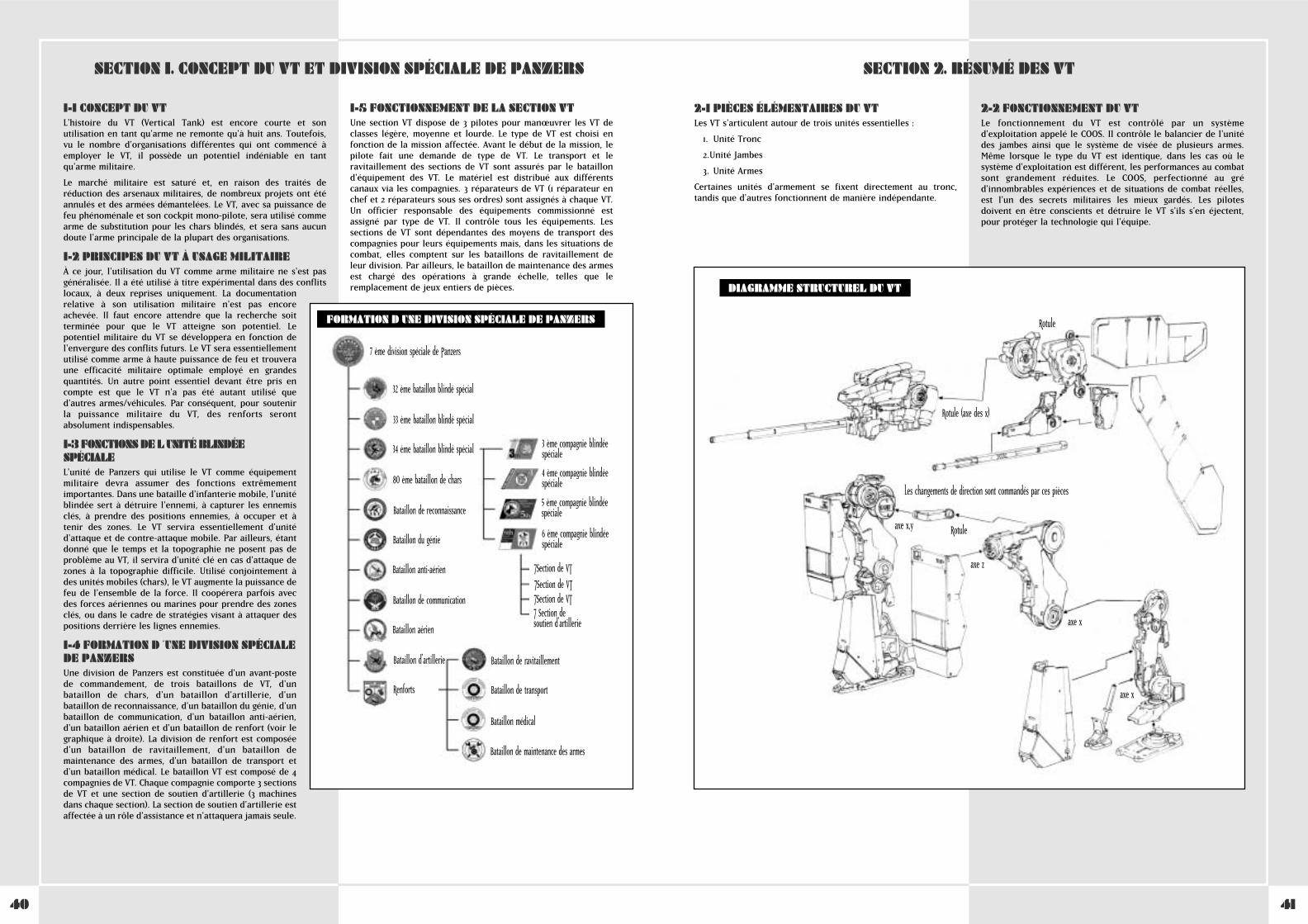
4140
2-1 PIÈCES ÉLÉMENTAIRES DU VTLes VT s'articulent autour de trois unités essentielles :
1. Unité Tronc
2.Unité Jambes
3. Unité Armes
Certaines unités d'armement se fixent directement au tronc,tandis que d'autres fonctionnent de manière indépendante.
2-2 FONCTIONNEMENT DU VTLe fonctionnement du VT est contrôlé par un systèmed'exploitation appelé le COOS. Il contrôle le balancier de l'unitédes jambes ainsi que le système de visée de plusieurs armes.Même lorsque le type du VT est identique, dans les cas où lesystème d'exploitation est différent, les performances au combatsont grandement réduites. Le COOS, perfectionné au gréd'innombrables expériences et de situations de combat réelles,est l'un des secrets militaires les mieux gardés. Les pilotesdoivent en être conscients et détruire le VT s'ils s'en éjectent,pour protéger la technologie qui l'équipe.
1-1 CONCEPT DU VTL'histoire du VT (Vertical Tank) est encore courte et sonutilisation en tant qu'arme ne remonte qu'à huit ans. Toutefois,vu le nombre d'organisations différentes qui ont commencé àemployer le VT, il possède un potentiel indéniable en tantqu'arme militaire.
Le marché militaire est saturé et, en raison des traités deréduction des arsenaux militaires, de nombreux projets ont étéannulés et des armées démantelées. Le VT, avec sa puissance defeu phénoménale et son cockpit mono-pilote, sera utilisé commearme de substitution pour les chars blindés, et sera sans aucundoute l'arme principale de la plupart des organisations.
1-2 PRINCIPES DU VT À USAGE MILITAIREÀ ce jour, l'utilisation du VT comme arme militaire ne s'est pasgénéralisée. Il a été utilisé à titre expérimental dans des conflitslocaux, à deux reprises uniquement. La documentationrelative à son utilisation militaire n'est pas encoreachevée. Il faut encore attendre que la recherche soitterminée pour que le VT atteigne son potentiel. Lepotentiel militaire du VT se développera en fonction del'envergure des conflits futurs. Le VT sera essentiellementutilisé comme arme à haute puissance de feu et trouveraune efficacité militaire optimale employé en grandesquantités. Un autre point essentiel devant être pris encompte est que le VT n'a pas été autant utilisé qued'autres armes/véhicules. Par conséquent, pour soutenirla puissance militaire du VT, des renforts serontabsolument indispensables.
1-3 FONCTIONS DE L UNITÉ BLINDÉESPÉCIALEL'unité de Panzers qui utilise le VT comme équipementmilitaire devra assumer des fonctions extrêmementimportantes. Dans une bataille d'infanterie mobile, l'unitéblindée sert à détruire l'ennemi, à capturer les ennemisclés, à prendre des positions ennemies, à occuper et àtenir des zones. Le VT servira essentiellement d'unitéd'attaque et de contre-attaque mobile. Par ailleurs, étantdonné que le temps et la topographie ne posent pas deproblème au VT, il servira d'unité clé en cas d'attaque dezones à la topographie difficile. Utilisé conjointement àdes unités mobiles (chars), le VT augmente la puissance defeu de l'ensemble de la force. Il coopérera parfois avecdes forces aériennes ou marines pour prendre des zonesclés, ou dans le cadre de stratégies visant à attaquer despositions derrière les lignes ennemies.
1-4 FORMATION D ´UNE DIVISION SPÉCIALEDE PANZERSUne division de Panzers est constituée d'un avant-postede commandement, de trois bataillons de VT, d'unbataillon de chars, d'un bataillon d'artillerie, d'unbataillon de reconnaissance, d'un bataillon du génie, d'unbataillon de communication, d'un bataillon anti-aérien,d'un bataillon aérien et d'un bataillon de renfort (voir legraphique à droite). La division de renfort est composéed'un bataillon de ravitaillement, d'un bataillon demaintenance des armes, d'un bataillon de transport etd'un bataillon médical. Le bataillon VT est composé de 4compagnies de VT. Chaque compagnie comporte 3 sectionsde VT et une section de soutien d'artillerie (3 machinesdans chaque section). La section de soutien d'artillerie estaffectée à un rôle d'assistance et n'attaquera jamais seule.
1-5 FONCTIONNEMENT DE LA SECTION VTUne section VT dispose de 3 pilotes pour manœuvrer les VT declasses légère, moyenne et lourde. Le type de VT est choisi enfonction de la mission affectée. Avant le début de la mission, lepilote fait une demande de type de VT. Le transport et leravitaillement des sections de VT sont assurés par le bataillond'équipement des VT. Le matériel est distribué aux différentscanaux via les compagnies. 3 réparateurs de VT (1 réparateur enchef et 2 réparateurs sous ses ordres) sont assignés à chaque VT.Un officier responsable des équipements commissionné estassigné par type de VT. Il contrôle tous les équipements. Lessections de VT sont dépendantes des moyens de transport descompagnies pour leurs équipements mais, dans les situations decombat, elles comptent sur les bataillons de ravitaillement deleur division. Par ailleurs, le bataillon de maintenance des armesest chargé des opérations à grande échelle, telles que leremplacement de jeux entiers de pièces.
SECTION 1. CONCEPT DU VT ET DIVISION SPÉCIALE DE PANZERS SECTION 2. RÉSUMÉ DES VT
7 ème division spéciale de Panzers
32 ème bataillon blindé spécial
33 ème bataillon blindé spécial
34 ème bataillon blindé spécial 3 ème compagnie blindéespéciale
4 ème compagnie blindéespéciale
5 ème compagnie blindéespéciale
6 ème compagnie blindéespéciale
‡Section de VT‡Section de VT‡Section de VT‡ Section desoutien d'artillerie
Bataillon de ravitaillement
Bataillon de transport
Bataillon médical
Bataillon de maintenance des armes
80 ème bataillon de chars
Bataillon de reconnaissance
Bataillon du génie
Bataillon anti-aérien
Bataillon de communication
Bataillon aérien
Bataillon d'artillerie
Renforts
FORMATION D UNE DIVISION SPÉCIALE DE PANZERS
DIAGRAMME STRUCTUREL DU VT
Rotule (axe des x)
axe x,y
axe z
axe x
axe x
Les changements de direction sont commandés par ces pièces
Rotule
Rotule
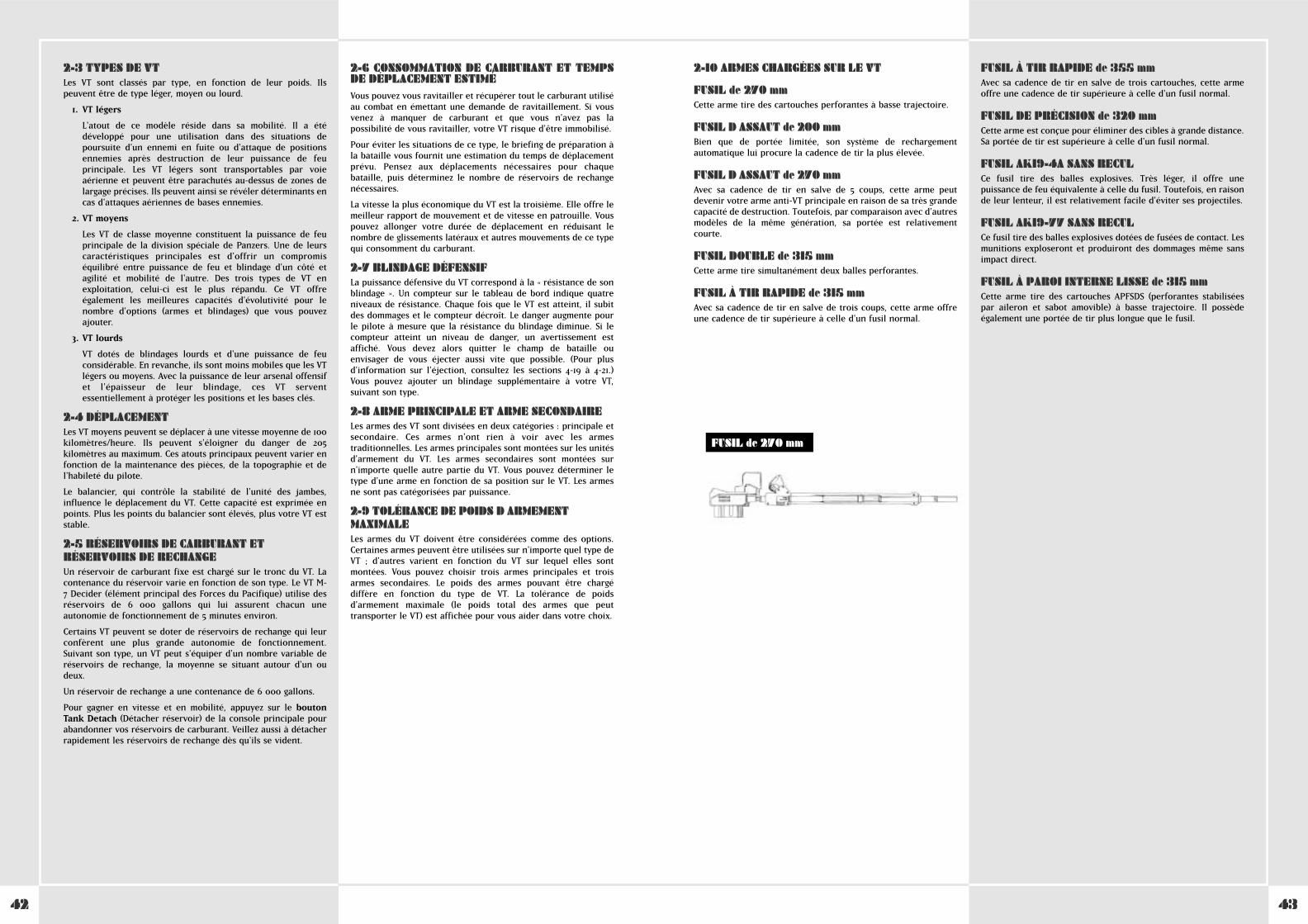
4342
2-10 ARMES CHARGÉES SUR LE VT
FUSIL de 270 mmCette arme tire des cartouches perforantes à basse trajectoire.
FUSIL D ASSAUT de 200 mmBien que de portée limitée, son système de rechargementautomatique lui procure la cadence de tir la plus élevée.
FUSIL D ASSAUT de 270 mmAvec sa cadence de tir en salve de 5 coups, cette arme peutdevenir votre arme anti-VT principale en raison de sa très grandecapacité de destruction. Toutefois, par comparaison avec d'autresmodèles de la même génération, sa portée est relativementcourte.
FUSIL DOUBLE de 315 mmCette arme tire simultanément deux balles perforantes.
FUSIL À TIR RAPIDE de 315 mmAvec sa cadence de tir en salve de trois coups, cette arme offreune cadence de tir supérieure à celle d'un fusil normal.
FUSIL À TIR RAPIDE de 355 mmAvec sa cadence de tir en salve de trois cartouches, cette armeoffre une cadence de tir supérieure à celle d'un fusil normal.
FUSIL DE PRÉCISION de 320 mmCette arme est conçue pour éliminer des cibles à grande distance.Sa portée de tir est supérieure à celle d'un fusil normal.
FUSIL AK19-4A SANS RECULCe fusil tire des balles explosives. Très léger, il offre unepuissance de feu équivalente à celle du fusil. Toutefois, en raisonde leur lenteur, il est relativement facile d'éviter ses projectiles.
FUSIL AK19-77 SANS RECULCe fusil tire des balles explosives dotées de fusées de contact. Lesmunitions exploseront et produiront des dommages même sansimpact direct.
FUSIL À PAROI INTERNE LISSE de 315 mmCette arme tire des cartouches APFSDS (perforantes stabiliséespar aileron et sabot amovible) à basse trajectoire. Il possèdeégalement une portée de tir plus longue que le fusil.
2-3 TYPES DE VTLes VT sont classés par type, en fonction de leur poids. Ilspeuvent être de type léger, moyen ou lourd.
1. VT légers
L'atout de ce modèle réside dans sa mobilité. Il a étédéveloppé pour une utilisation dans des situations depoursuite d'un ennemi en fuite ou d'attaque de positionsennemies après destruction de leur puissance de feuprincipale. Les VT légers sont transportables par voieaérienne et peuvent être parachutés au-dessus de zones delargage précises. Ils peuvent ainsi se révéler déterminants encas d'attaques aériennes de bases ennemies.
2. VT moyens
Les VT de classe moyenne constituent la puissance de feuprincipale de la division spéciale de Panzers. Une de leurscaractéristiques principales est d'offrir un compromiséquilibré entre puissance de feu et blindage d'un côté etagilité et mobilité de l'autre. Des trois types de VT enexploitation, celui-ci est le plus répandu. Ce VT offreégalement les meilleures capacités d'évolutivité pour lenombre d'options (armes et blindages) que vous pouvezajouter.
3. VT lourds
VT dotés de blindages lourds et d'une puissance de feuconsidérable. En revanche, ils sont moins mobiles que les VTlégers ou moyens. Avec la puissance de leur arsenal offensifet l'épaisseur de leur blindage, ces VT serventessentiellement à protéger les positions et les bases clés.
2-4 DÉPLACEMENTLes VT moyens peuvent se déplacer à une vitesse moyenne de 100kilomètres/heure. Ils peuvent s'éloigner du danger de 205kilomètres au maximum. Ces atouts principaux peuvent varier enfonction de la maintenance des pièces, de la topographie et del'habileté du pilote.
Le balancier, qui contrôle la stabilité de l'unité des jambes,influence le déplacement du VT. Cette capacité est exprimée enpoints. Plus les points du balancier sont élevés, plus votre VT eststable.
2-5 RÉSERVOIRS DE CARBURANT ETRÉSERVOIRS DE RECHANGEUn réservoir de carburant fixe est chargé sur le tronc du VT. Lacontenance du réservoir varie en fonction de son type. Le VT M-7 Decider (élément principal des Forces du Pacifique) utilise desréservoirs de 6 000 gallons qui lui assurent chacun uneautonomie de fonctionnement de 5 minutes environ.
Certains VT peuvent se doter de réservoirs de rechange qui leurconfèrent une plus grande autonomie de fonctionnement.Suivant son type, un VT peut s'équiper d'un nombre variable deréservoirs de rechange, la moyenne se situant autour d'un oudeux.
Un réservoir de rechange a une contenance de 6 000 gallons.
Pour gagner en vitesse et en mobilité, appuyez sur le boutonTank Detach (Détacher réservoir) de la console principale pourabandonner vos réservoirs de carburant. Veillez aussi à détacherrapidement les réservoirs de rechange dès qu'ils se vident.
2-6 CONSOMMATION DE CARBURANT ET TEMPSDE DÉPLACEMENT ESTIMÉVous pouvez vous ravitailler et récupérer tout le carburant utiliséau combat en émettant une demande de ravitaillement. Si vousvenez à manquer de carburant et que vous n'avez pas lapossibilité de vous ravitailler, votre VT risque d'être immobilisé.
Pour éviter les situations de ce type, le briefing de préparation àla bataille vous fournit une estimation du temps de déplacementprévu. Pensez aux déplacements nécessaires pour chaquebataille, puis déterminez le nombre de réservoirs de rechangenécessaires.
La vitesse la plus économique du VT est la troisième. Elle offre lemeilleur rapport de mouvement et de vitesse en patrouille. Vouspouvez allonger votre durée de déplacement en réduisant lenombre de glissements latéraux et autres mouvements de ce typequi consomment du carburant.
2-7 BLINDAGE DÉFENSIFLa puissance défensive du VT correspond à la « résistance de sonblindage ». Un compteur sur le tableau de bord indique quatreniveaux de résistance. Chaque fois que le VT est atteint, il subitdes dommages et le compteur décroît. Le danger augmente pourle pilote à mesure que la résistance du blindage diminue. Si lecompteur atteint un niveau de danger, un avertissement estaffiché. Vous devez alors quitter le champ de bataille ouenvisager de vous éjecter aussi vite que possible. (Pour plusd'information sur l'éjection, consultez les sections 4-19 à 4-21.)Vous pouvez ajouter un blindage supplémentaire à votre VT,suivant son type.
2-8 ARME PRINCIPALE ET ARME SECONDAIRELes armes des VT sont divisées en deux catégories : principale etsecondaire. Ces armes n'ont rien à voir avec les armestraditionnelles. Les armes principales sont montées sur les unitésd'armement du VT. Les armes secondaires sont montées surn'importe quelle autre partie du VT. Vous pouvez déterminer letype d'une arme en fonction de sa position sur le VT. Les armesne sont pas catégorisées par puissance.
2-9 TOLÉRANCE DE POIDS D ARMEMENTMAXIMALELes armes du VT doivent être considérées comme des options.Certaines armes peuvent être utilisées sur n'importe quel type deVT ; d'autres varient en fonction du VT sur lequel elles sontmontées. Vous pouvez choisir trois armes principales et troisarmes secondaires. Le poids des armes pouvant être chargédiffère en fonction du type de VT. La tolérance de poidsd'armement maximale (le poids total des armes que peuttransporter le VT) est affichée pour vous aider dans votre choix.
FUSIL de 270 mm
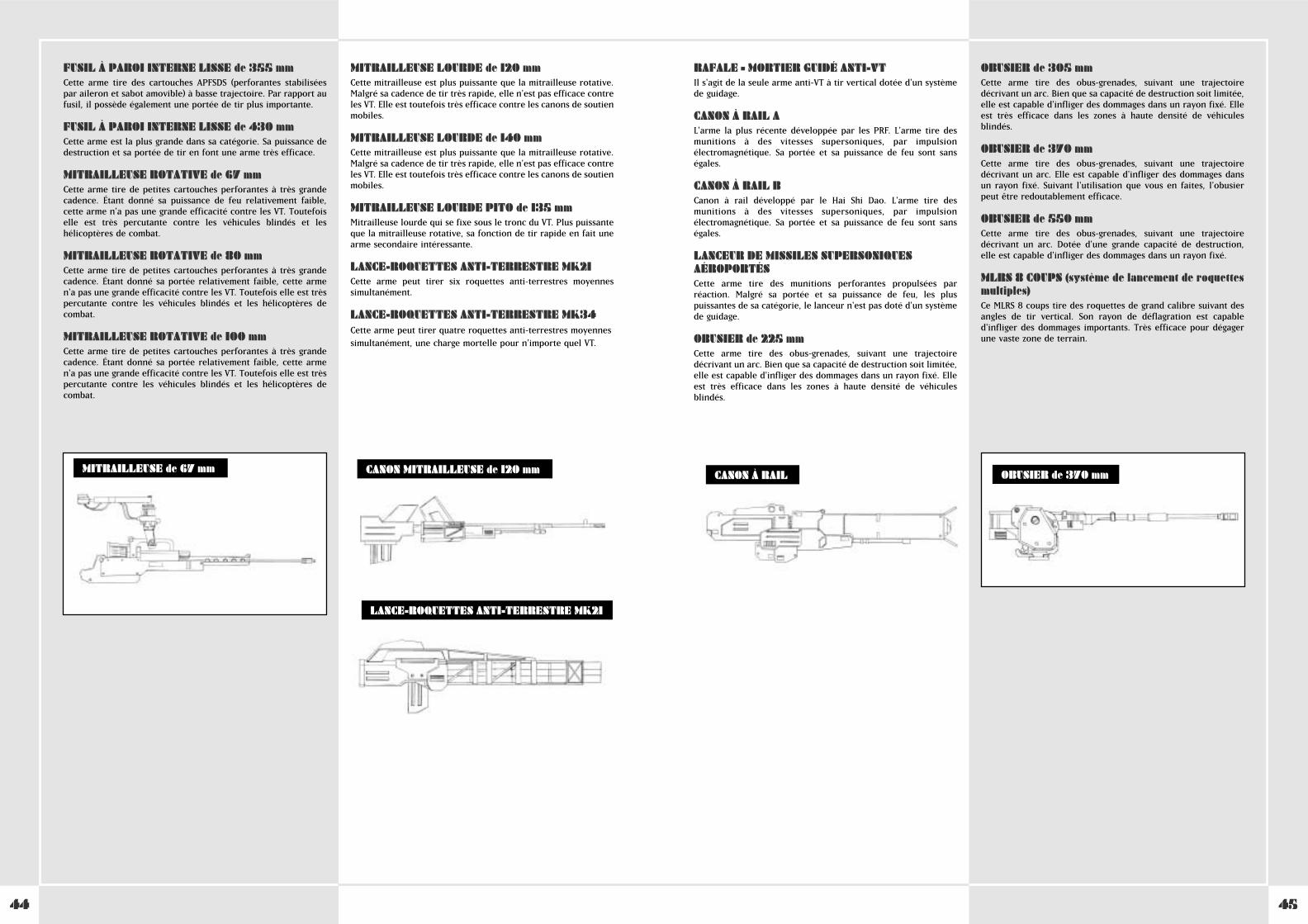
4544
RAFALE – MORTIER GUIDÉ ANTI-VTIl s'agit de la seule arme anti-VT à tir vertical dotée d'un systèmede guidage.
CANON À RAIL AL'arme la plus récente développée par les PRF. L'arme tire desmunitions à des vitesses supersoniques, par impulsionélectromagnétique. Sa portée et sa puissance de feu sont sanségales.
CANON À RAIL BCanon à rail développé par le Hai Shi Dao. L'arme tire desmunitions à des vitesses supersoniques, par impulsionélectromagnétique. Sa portée et sa puissance de feu sont sanségales.
LANCEUR DE MISSILES SUPERSONIQUESAÉROPORTÉSCette arme tire des munitions perforantes propulsées parréaction. Malgré sa portée et sa puissance de feu, les pluspuissantes de sa catégorie, le lanceur n'est pas doté d'un systèmede guidage.
OBUSIER de 225 mmCette arme tire des obus-grenades, suivant une trajectoiredécrivant un arc. Bien que sa capacité de destruction soit limitée,elle est capable d'infliger des dommages dans un rayon fixé. Elleest très efficace dans les zones à haute densité de véhiculesblindés.
OBUSIER de 305 mmCette arme tire des obus-grenades, suivant une trajectoiredécrivant un arc. Bien que sa capacité de destruction soit limitée,elle est capable d'infliger des dommages dans un rayon fixé. Elleest très efficace dans les zones à haute densité de véhiculesblindés.
OBUSIER de 370 mmCette arme tire des obus-grenades, suivant une trajectoiredécrivant un arc. Elle est capable d'infliger des dommages dansun rayon fixé. Suivant l'utilisation que vous en faites, l'obusierpeut être redoutablement efficace.
OBUSIER de 550 mmCette arme tire des obus-grenades, suivant une trajectoiredécrivant un arc. Dotée d'une grande capacité de destruction,elle est capable d'infliger des dommages dans un rayon fixé.
MLRS 8 COUPS (système de lancement de roquettesmultiples)Ce MLRS 8 coups tire des roquettes de grand calibre suivant desangles de tir vertical. Son rayon de déflagration est capabled'infliger des dommages importants. Très efficace pour dégagerune vaste zone de terrain.
FUSIL À PAROI INTERNE LISSE de 355 mmCette arme tire des cartouches APFSDS (perforantes stabiliséespar aileron et sabot amovible) à basse trajectoire. Par rapport aufusil, il possède également une portée de tir plus importante.
FUSIL À PAROI INTERNE LISSE de 430 mmCette arme est la plus grande dans sa catégorie. Sa puissance dedestruction et sa portée de tir en font une arme très efficace.
MITRAILLEUSE ROTATIVE de 67 mmCette arme tire de petites cartouches perforantes à très grandecadence. Étant donné sa puissance de feu relativement faible,cette arme n'a pas une grande efficacité contre les VT. Toutefoiselle est très percutante contre les véhicules blindés et leshélicoptères de combat.
MITRAILLEUSE ROTATIVE de 80 mmCette arme tire de petites cartouches perforantes à très grandecadence. Étant donné sa portée relativement faible, cette armen'a pas une grande efficacité contre les VT. Toutefois elle est trèspercutante contre les véhicules blindés et les hélicoptères decombat.
MITRAILLEUSE ROTATIVE de 100 mmCette arme tire de petites cartouches perforantes à très grandecadence. Étant donné sa portée relativement faible, cette armen'a pas une grande efficacité contre les VT. Toutefois elle est trèspercutante contre les véhicules blindés et les hélicoptères decombat.
MITRAILLEUSE LOURDE de 120 mmCette mitrailleuse est plus puissante que la mitrailleuse rotative.Malgré sa cadence de tir très rapide, elle n'est pas efficace contreles VT. Elle est toutefois très efficace contre les canons de soutienmobiles.
MITRAILLEUSE LOURDE de 140 mmCette mitrailleuse est plus puissante que la mitrailleuse rotative.Malgré sa cadence de tir très rapide, elle n'est pas efficace contreles VT. Elle est toutefois très efficace contre les canons de soutienmobiles.
MITRAILLEUSE LOURDE PITO de 135 mmMitrailleuse lourde qui se fixe sous le tronc du VT. Plus puissanteque la mitrailleuse rotative, sa fonction de tir rapide en fait unearme secondaire intéressante.
LANCE-ROQUETTES ANTI-TERRESTRE MK21Cette arme peut tirer six roquettes anti-terrestres moyennessimultanément.
LANCE-ROQUETTES ANTI-TERRESTRE MK34Cette arme peut tirer quatre roquettes anti-terrestres moyennes
simultanément, une charge mortelle pour n'importe quel VT.
CANON À RAIL OBUSIER de 370 mmMITRAILLEUSE de 67 mm CANON MITRAILLEUSE de 120 mm
LANCE-ROQUETTES ANTI-TERRESTRE MK21
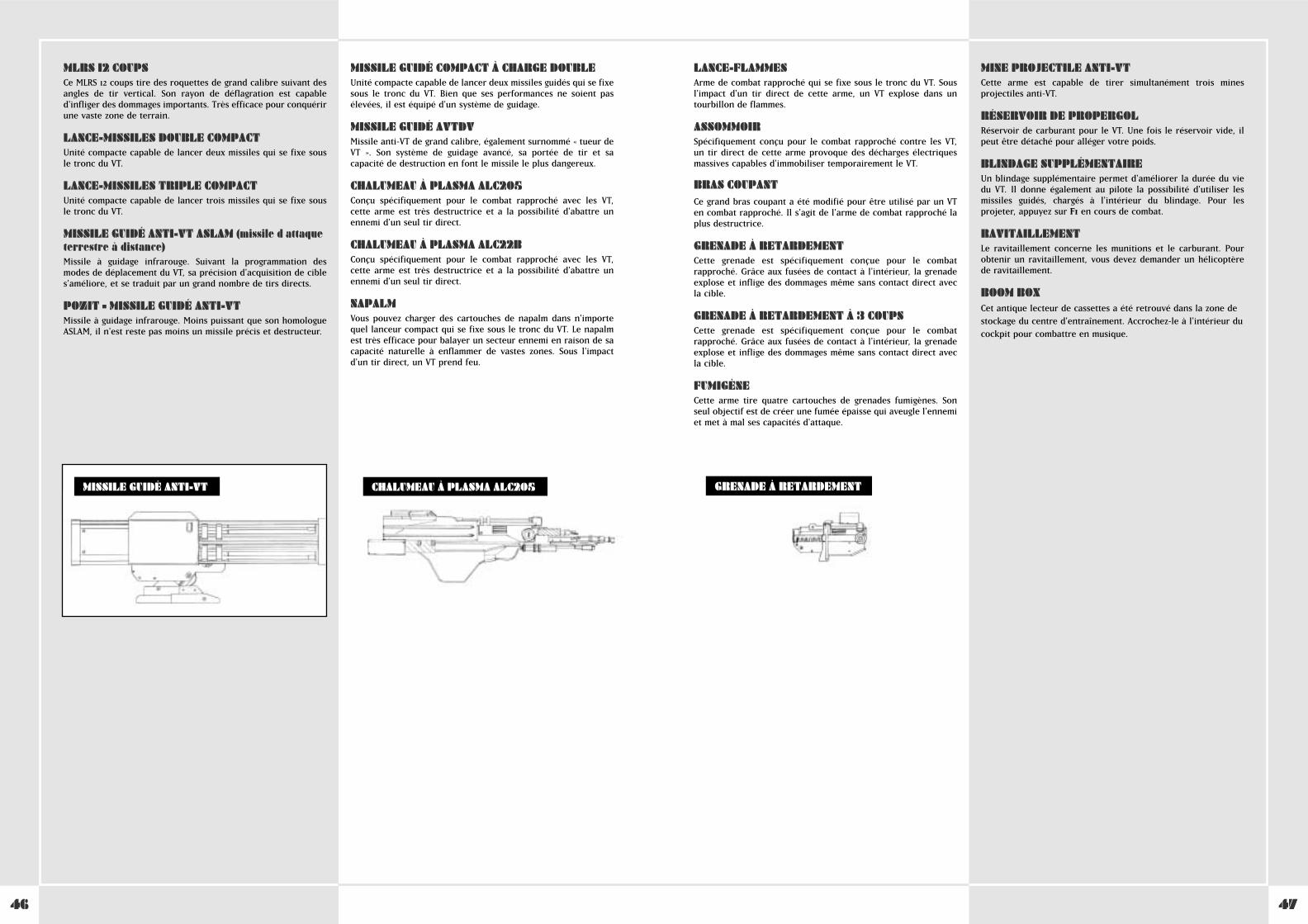
4746
LANCE-FLAMMESArme de combat rapproché qui se fixe sous le tronc du VT. Sousl'impact d'un tir direct de cette arme, un VT explose dans untourbillon de flammes.
ASSOMMOIRSpécifiquement conçu pour le combat rapproché contre les VT,un tir direct de cette arme provoque des décharges électriquesmassives capables d'immobiliser temporairement le VT.
BRAS COUPANTCe grand bras coupant a été modifié pour être utilisé par un VTen combat rapproché. Il s'agit de l'arme de combat rapproché laplus destructrice.
GRENADE À RETARDEMENTCette grenade est spécifiquement conçue pour le combatrapproché. Grâce aux fusées de contact à l'intérieur, la grenadeexplose et inflige des dommages même sans contact direct avecla cible.
GRENADE À RETARDEMENT À 3 COUPSCette grenade est spécifiquement conçue pour le combatrapproché. Grâce aux fusées de contact à l'intérieur, la grenadeexplose et inflige des dommages même sans contact direct avecla cible.
FUMIGÈNECette arme tire quatre cartouches de grenades fumigènes. Sonseul objectif est de créer une fumée épaisse qui aveugle l'ennemiet met à mal ses capacités d'attaque.
MINE PROJECTILE ANTI-VTCette arme est capable de tirer simultanément trois minesprojectiles anti-VT.
RÉSERVOIR DE PROPERGOLRéservoir de carburant pour le VT. Une fois le réservoir vide, ilpeut être détaché pour alléger votre poids.
BLINDAGE SUPPLÉMENTAIREUn blindage supplémentaire permet d'améliorer la durée du viedu VT. Il donne également au pilote la possibilité d'utiliser lesmissiles guidés, chargés à l'intérieur du blindage. Pour lesprojeter, appuyez sur F1 en cours de combat.
RAVITAILLEMENTLe ravitaillement concerne les munitions et le carburant. Pourobtenir un ravitaillement, vous devez demander un hélicoptèrede ravitaillement.
BOOM BOXCet antique lecteur de cassettes a été retrouvé dans la zone de
stockage du centre d'entraînement. Accrochez-le à l'intérieur du
cockpit pour combattre en musique.
MLRS 12 COUPSCe MLRS 12 coups tire des roquettes de grand calibre suivant desangles de tir vertical. Son rayon de déflagration est capabled'infliger des dommages importants. Très efficace pour conquérirune vaste zone de terrain.
LANCE-MISSILES DOUBLE COMPACTUnité compacte capable de lancer deux missiles qui se fixe sousle tronc du VT.
LANCE-MISSILES TRIPLE COMPACTUnité compacte capable de lancer trois missiles qui se fixe sousle tronc du VT.
MISSILE GUIDÉ ANTI-VT ASLAM (missile d attaqueterrestre à distance)Missile à guidage infrarouge. Suivant la programmation desmodes de déplacement du VT, sa précision d'acquisition de cibles'améliore, et se traduit par un grand nombre de tirs directs.
POZIT – MISSILE GUIDÉ ANTI-VTMissile à guidage infrarouge. Moins puissant que son homologueASLAM, il n'est reste pas moins un missile précis et destructeur.
MISSILE GUIDÉ COMPACT À CHARGE DOUBLEUnité compacte capable de lancer deux missiles guidés qui se fixesous le tronc du VT. Bien que ses performances ne soient pasélevées, il est équipé d'un système de guidage.
MISSILE GUIDÉ AVTDVMissile anti-VT de grand calibre, également surnommé « tueur deVT ». Son système de guidage avancé, sa portée de tir et sacapacité de destruction en font le missile le plus dangereux.
CHALUMEAU À PLASMA ALC205Conçu spécifiquement pour le combat rapproché avec les VT,cette arme est très destructrice et a la possibilité d'abattre unennemi d'un seul tir direct.
CHALUMEAU À PLASMA ALC22BConçu spécifiquement pour le combat rapproché avec les VT,cette arme est très destructrice et a la possibilité d'abattre unennemi d'un seul tir direct.
NAPALMVous pouvez charger des cartouches de napalm dans n'importequel lanceur compact qui se fixe sous le tronc du VT. Le napalmest très efficace pour balayer un secteur ennemi en raison de sacapacité naturelle à enflammer de vastes zones. Sous l'impactd'un tir direct, un VT prend feu.
CHALUMEAU À PLASMA ALC205MISSILE GUIDÉ ANTI-VT GRENADE À RETARDEMENT
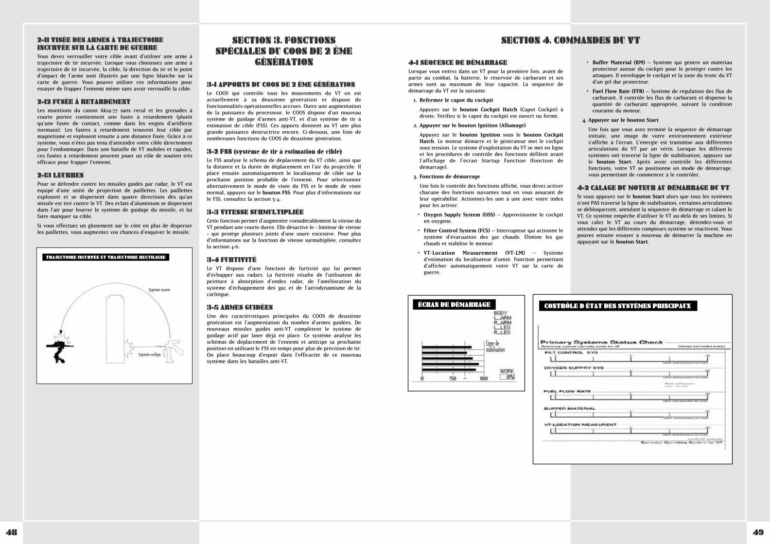
4948
2-11 VISÉE DES ARMES À TRAJECTOIREINCURVÉE SUR LA CARTE DE GUERREVous devez verrouiller votre cible avant d'utiliser une arme àtrajectoire de tir incurvée. Lorsque vous choisissez une arme àtrajectoire de tir incurvée, la cible, la direction du tir et le pointd'impact de l'arme sont illustrés par une ligne blanche sur lacarte de guerre. Vous pouvez utiliser ces informations pouressayer de frapper l'ennemi même sans avoir verrouillé la cible.
2-12 FUSÉE À RETARDEMENTLes munitions du canon Ak19-77 sans recul et les grenades àcourte portée contiennent une fusée à retardement (plutôtqu'une fusée de contact, comme dans les engins d'artillerienormaux). Les fusées à retardement trouvent leur cible parmagnétisme et explosent ensuite à une distance fixée. Grâce à cesystème, vous n'êtes pas tenu d'atteindre votre cible directementpour l'endommager. Dans une bataille de VT mobiles et rapides,ces fusées à retardement peuvent jouer un rôle de soutien trèsefficace pour frapper l'ennemi.
2-13 LEURRESPour se défendre contre les missiles guidés par radar, le VT estéquipé d'une unité de projection de paillettes. Les paillettesexplosent et se dispersent dans quatre directions dès qu'unmissile est tiré contre le VT. Des éclats d'aluminium se dispersentdans l'air pour leurrer le système de guidage du missile, et luifaire manquer sa cible.
Si vous effectuez un glissement sur le côté en plus de disperserles paillettes, vous augmentez vos chances d'esquiver le missile.
TRAJECTOIRE INCURVÉE ET TRAJECTOIRE RECTILIGNE
Trajectoire incurvée
Trajectoire rectiligne
3-1 APPORTS DU COOS DE 2 ÈME GÉNÉRATIONLe COOS qui contrôle tous les mouvements du VT en estactuellement à sa deuxième génération et dispose defonctionnalités opérationnelles accrues. Outre une augmentationde la puissance du processeur, le COOS dispose d'un nouveausystème de guidage d'armes anti-VT, et d'un système de tir àestimation de cible (FSS). Ces apports donnent au VT une plusgrande puissance destructrice encore. Ci-dessous, une liste denombreuses fonctions du COOS de deuxième génération.
3-2 FSS (système de tir à estimation de cible)Le FSS analyse le schéma de déplacement du VT cible, ainsi quela distance et la durée de déplacement en l'air du projectile. Ilplace ensuite automatiquement le localisateur de cible sur laprochaine position probable de l'ennemi. Pour sélectionneralternativement le mode de visée du FSS et le mode de viséenormal, appuyez sur le bouton FSS. Pour plus d'informations surle FSS, consultez la section 5-4.
3-3 VITESSE SURMULTIPLIÉECette fonction permet d'augmenter considérablement la vitesse duVT pendant une courte durée. Elle désactive le « limiteur de vitesse» qui protège plusieurs joints d'une usure excessive. Pour plusd'informations sur la fonction de vitesse surmultipliée, consultezla section 4-6.
3-4 FURTIVITÉLe VT dispose d'une fonction de furtivité qui lui permetd'échapper aux radars. La furtivité résulte de l'utilisation depeinture à absorption d'ondes radar, de l'amélioration dusystème d'échappement des gaz et de l'aérodynamisme de lacarlingue.
3-5 ARMES GUIDÉESUne des caractéristiques principales du COOS de deuxièmegénération est l'augmentation du nombre d'armes guidées. Denouveaux missiles guidés anti-VT complètent le système deguidage actif par laser déjà en place. Ce système analyse lesschémas de déplacement de l'ennemi et anticipe sa prochaineposition en utilisant le FSS en temps pour plus de précision de tir.On place beaucoup d'espoir dans l'efficacité de ce nouveausystème dans les batailles anti-VT.
SECTION 3. FONCTIONSSPÉCIALES DU COOS DE 2 ÈME
GÉNÉRATION 4-1 SÉQUENCE DE DÉMARRAGELorsque vous entrez dans un VT pour la première fois, avant departir au combat, la batterie, le réservoir de carburant et sesarmes sont au maximum de leur capacité. La séquence dedémarrage du VT est la suivante.
1. Refermer le capot du cockpit
Appuyez sur le bouton Cockpit Hatch (Capot Cockpit) àdroite. Vérifiez si le capot du cockpit est ouvert ou fermé.
2. Appuyer sur le bouton Ignition (Allumage)
Appuyez sur le bouton Ignition sous le bouton CockpitHatch. Le moteur démarre et le générateur met le cockpitsous tension. Le système d'exploitation du VT se met en ligneet les procédures de contrôle des fonctions défilent avantl'affichage de l'écran Startup Function (fonction dedémarrage).
3. Fonctions de démarrage
Une fois le contrôle des fonctions affiché, vous devez activerchacune des fonctions suivantes tout en vous assurant deleur opérabilité. Actionnez-les une à une avec votre indexpour les activer.
• Oxygen Supply System (OSS) – Approvisionne le cockpiten oxygène.
• Filter Control System (FCS) – Interrupteur qui actionne lesystème d'évacuation des gaz chauds. Élimine les gazchauds et stabilise le moteur.
• VT-Location Measurement (VT-LM) – Systèmed'estimation du localisateur d'unité. Fonction permettantd'afficher automatiquement votre VT sur la carte deguerre.
• Buffer Material (BM) – Système qui génère un matériauprotecteur autour du cockpit pour le protéger contre lesattaques. Il enveloppe le cockpit et la zone du tronc du VTd'un gel dur protecteur.
• Fuel Flow Rate (FFR) – Système de régulation des flux decarburant. Il contrôle les flux de carburant et dispense laquantité de carburant appropriée, suivant la conditioncourante du moteur.
4. Appuyer sur le bouton Start
Une fois que vous avez terminé la séquence de démarrageinitiale, une image de votre environnement extérieurs'affiche à l'écran. L'énergie est transmise aux différentesarticulations du VT par un vérin. Lorsque les différentssystèmes ont traversé la ligne de stabilisation, appuyez surle bouton Start. Après avoir contrôlé les différentesfonctions, votre VT se positionne en mode de démarrage,vous permettant de commencer à le contrôler.
4-2 CALAGE DU MOTEUR AU DÉMARRAGE DU VTSi vous appuyez sur le bouton Start alors que tous les systèmesn'ont PAS traversé la ligne de stabilisation, certaines articulationsse débloqueront, annulant la séquence de démarrage et calant leVT. Ce système empêche d'utiliser le VT au-delà de ses limites. Sivous calez le VT au cours du démarrage, détendez-vous etattendez que les différents compteurs système se réactivent. Vouspouvez ensuite essayer à nouveau de démarrer la machine enappuyant sur le bouton Start.
SECTION 4. COMMANDES DU VT
Ligne destabilisation
CONTRÔLE D ÉTAT DES SYSTÈMES PRINCIPAUXÉCRAN DE DÉMARRAGE
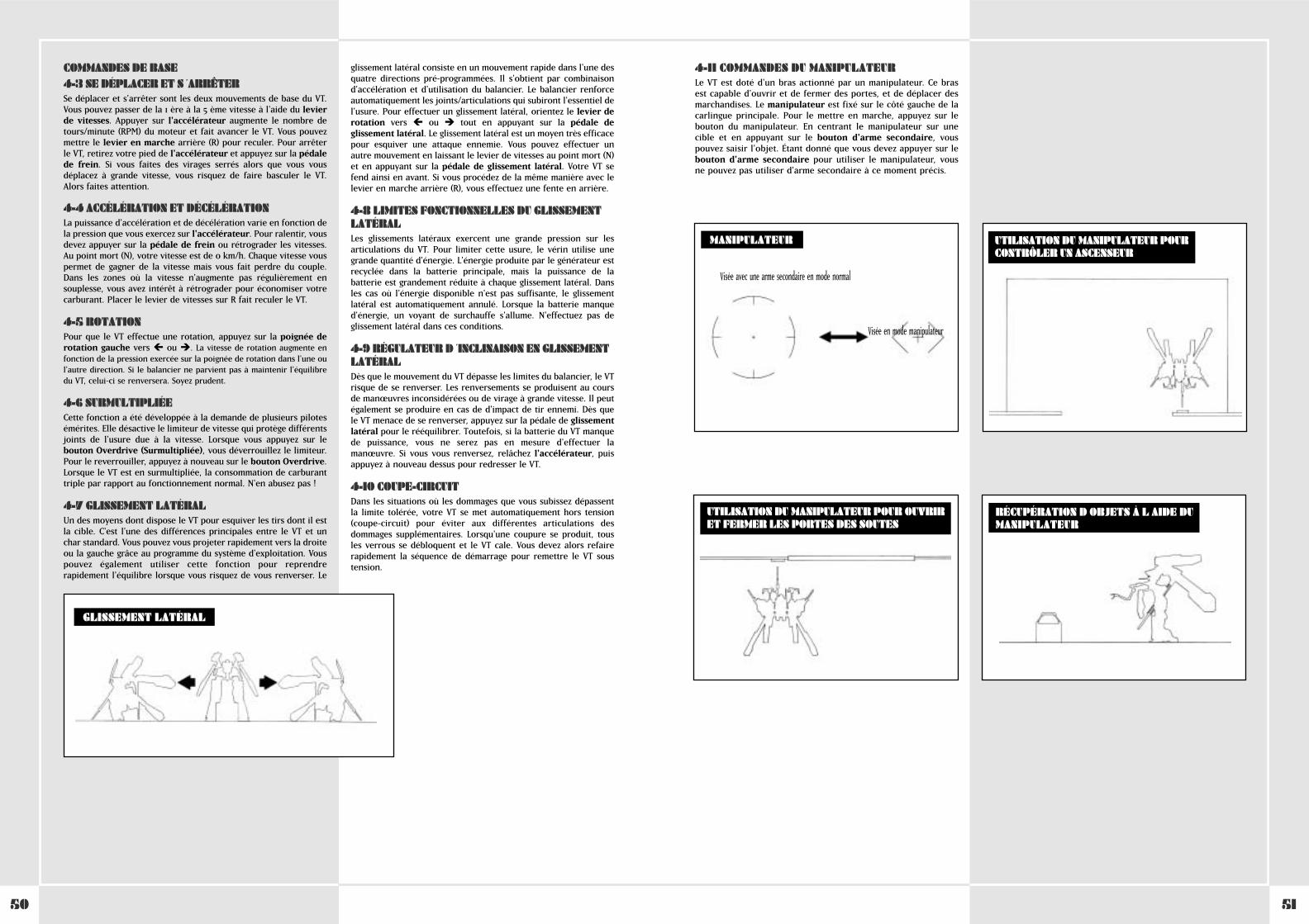
5150
COMMANDES DE BASE4-3 SE DÉPLACER ET S ´ARRÊTERSe déplacer et s'arrêter sont les deux mouvements de base du VT.Vous pouvez passer de la 1 ère à la 5 ème vitesse à l'aide du levierde vitesses. Appuyer sur l'accélérateur augmente le nombre detours/minute (RPM) du moteur et fait avancer le VT. Vous pouvezmettre le levier en marche arrière (R) pour reculer. Pour arrêterle VT, retirez votre pied de l'accélérateur et appuyez sur la pédalede frein. Si vous faites des virages serrés alors que vous vousdéplacez à grande vitesse, vous risquez de faire basculer le VT.Alors faites attention.
4-4 ACCÉLÉRATION ET DÉCÉLÉRATIONLa puissance d'accélération et de décélération varie en fonction dela pression que vous exercez sur l'accélérateur. Pour ralentir, vousdevez appuyer sur la pédale de frein ou rétrograder les vitesses.Au point mort (N), votre vitesse est de 0 km/h. Chaque vitesse vouspermet de gagner de la vitesse mais vous fait perdre du couple.Dans les zones où la vitesse n'augmente pas régulièrement ensouplesse, vous avez intérêt à rétrograder pour économiser votrecarburant. Placer le levier de vitesses sur R fait reculer le VT.
4-5 ROTATIONPour que le VT effectue une rotation, appuyez sur la poignée derotation gauche vers � ou �. La vitesse de rotation augmente enfonction de la pression exercée sur la poignée de rotation dans l'une oul'autre direction. Si le balancier ne parvient pas à maintenir l'équilibredu VT, celui-ci se renversera. Soyez prudent.
4-6 SURMULTIPLIÉECette fonction a été développée à la demande de plusieurs pilotesémérites. Elle désactive le limiteur de vitesse qui protège différentsjoints de l'usure due à la vitesse. Lorsque vous appuyez sur lebouton Overdrive (Surmultipliée), vous déverrouillez le limiteur.Pour le reverrouiller, appuyez à nouveau sur le bouton Overdrive.Lorsque le VT est en surmultipliée, la consommation de carburanttriple par rapport au fonctionnement normal. N'en abusez pas !
4-7 GLISSEMENT LATÉRALUn des moyens dont dispose le VT pour esquiver les tirs dont il estla cible. C'est l'une des différences principales entre le VT et unchar standard. Vous pouvez vous projeter rapidement vers la droiteou la gauche grâce au programme du système d'exploitation. Vouspouvez également utiliser cette fonction pour reprendrerapidement l'équilibre lorsque vous risquez de vous renverser. Le
glissement latéral consiste en un mouvement rapide dans l'une desquatre directions pré-programmées. Il s'obtient par combinaisond'accélération et d'utilisation du balancier. Le balancier renforceautomatiquement les joints/articulations qui subiront l'essentiel del'usure. Pour effectuer un glissement latéral, orientez le levier derotation vers � ou �̂ tout en appuyant sur la pédale deglissement latéral. Le glissement latéral est un moyen très efficacepour esquiver une attaque ennemie. Vous pouvez effectuer unautre mouvement en laissant le levier de vitesses au point mort (N)et en appuyant sur la pédale de glissement latéral. Votre VT sefend ainsi en avant. Si vous procédez de la même manière avec lelevier en marche arrière (R), vous effectuez une fente en arrière.
4-8 LIMITES FONCTIONNELLES DU GLISSEMENTLATÉRALLes glissements latéraux exercent une grande pression sur lesarticulations du VT. Pour limiter cette usure, le vérin utilise unegrande quantité d'énergie. L'énergie produite par le générateur estrecyclée dans la batterie principale, mais la puissance de labatterie est grandement réduite à chaque glissement latéral. Dansles cas où l'énergie disponible n'est pas suffisante, le glissementlatéral est automatiquement annulé. Lorsque la batterie manqued'énergie, un voyant de surchauffe s'allume. N'effectuez pas deglissement latéral dans ces conditions.
4-9 RÉGULATEUR D ´INCLINAISON EN GLISSEMENTLATÉRALDès que le mouvement du VT dépasse les limites du balancier, le VTrisque de se renverser. Les renversements se produisent au coursde manœuvres inconsidérées ou de virage à grande vitesse. Il peutégalement se produire en cas de d'impact de tir ennemi. Dès quele VT menace de se renverser, appuyez sur la pédale de glissementlatéral pour le rééquilibrer. Toutefois, si la batterie du VT manquede puissance, vous ne serez pas en mesure d'effectuer lamanœuvre. Si vous vous renversez, relâchez l'accélérateur, puisappuyez à nouveau dessus pour redresser le VT.
4-10 COUPE-CIRCUITDans les situations où les dommages que vous subissez dépassentla limite tolérée, votre VT se met automatiquement hors tension(coupe-circuit) pour éviter aux différentes articulations desdommages supplémentaires. Lorsqu'une coupure se produit, tousles verrous se débloquent et le VT cale. Vous devez alors refairerapidement la séquence de démarrage pour remettre le VT soustension.
GLISSEMENT LATÉRAL
4-11 COMMANDES DU MANIPULATEURLe VT est doté d'un bras actionné par un manipulateur. Ce brasest capable d'ouvrir et de fermer des portes, et de déplacer desmarchandises. Le manipulateur est fixé sur le côté gauche de lacarlingue principale. Pour le mettre en marche, appuyez sur lebouton du manipulateur. En centrant le manipulateur sur unecible et en appuyant sur le bouton d'arme secondaire, vouspouvez saisir l'objet. Étant donné que vous devez appuyer sur lebouton d'arme secondaire pour utiliser le manipulateur, vousne pouvez pas utiliser d'arme secondaire à ce moment précis.
UTILISATION DU MANIPULATEUR POURCONTRÔLER UN ASCENSEUR
UTILISATION DU MANIPULATEUR POUR OUVRIRET FERMER LES PORTES DES SOUTES
MANIPULATEUR
RÉCUPÉRATION D OBJETS À L AIDE DUMANIPULATEUR
Visée avec une arme secondaire en mode normal
Visée en mode manipulateur
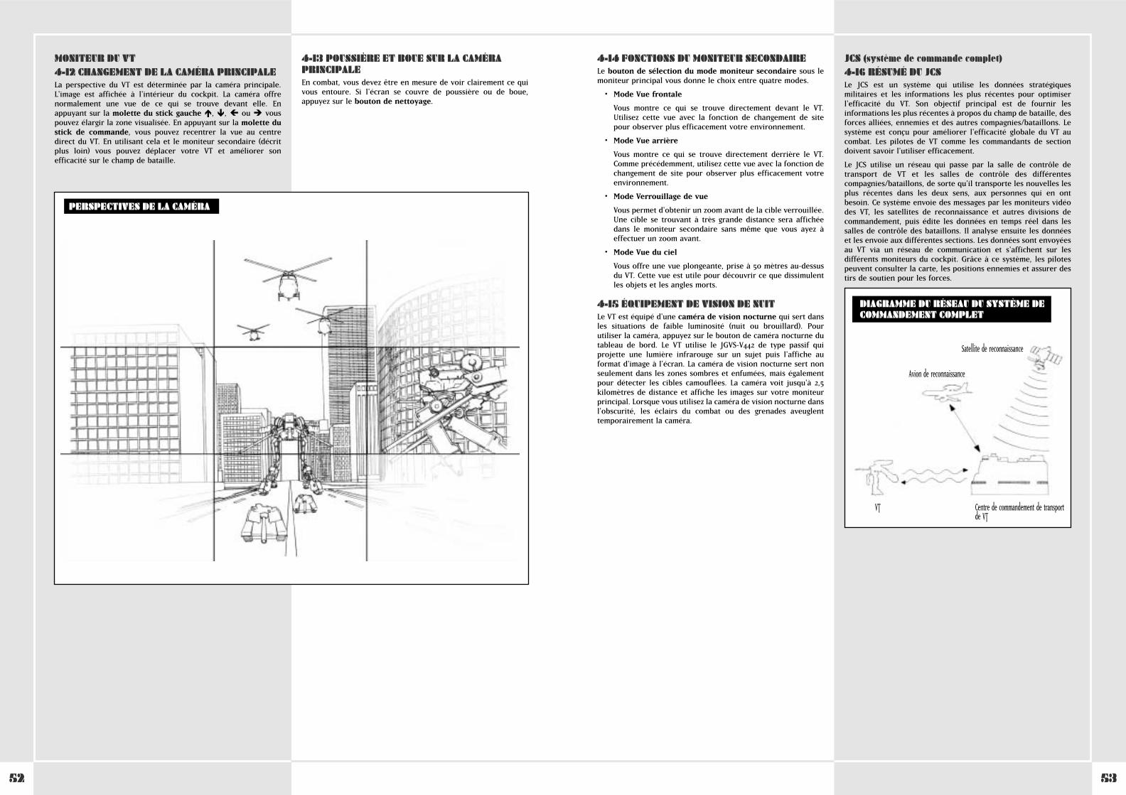
5352
MONITEUR DU VT4-12 CHANGEMENT DE LA CAMÉRA PRINCIPALELa perspective du VT est déterminée par la caméra principale.L'image est affichée à l'intérieur du cockpit. La caméra offrenormalement une vue de ce qui se trouve devant elle. Enappuyant sur la molette du stick gauche �, �, � ou � vouspouvez élargir la zone visualisée. En appuyant sur la molette dustick de commande, vous pouvez recentrer la vue au centredirect du VT. En utilisant cela et le moniteur secondaire (décritplus loin) vous pouvez déplacer votre VT et améliorer sonefficacité sur le champ de bataille.
4-13 POUSSIÈRE ET BOUE SUR LA CAMÉRAPRINCIPALEEn combat, vous devez être en mesure de voir clairement ce quivous entoure. Si l'écran se couvre de poussière ou de boue,appuyez sur le bouton de nettoyage.
PERSPECTIVES DE LA CAMÉRA
4-14 FONCTIONS DU MONITEUR SECONDAIRELe bouton de sélection du mode moniteur secondaire sous lemoniteur principal vous donne le choix entre quatre modes.
• Mode Vue frontale
Vous montre ce qui se trouve directement devant le VT.Utilisez cette vue avec la fonction de changement de sitepour observer plus efficacement votre environnement.
• Mode Vue arrière
Vous montre ce qui se trouve directement derrière le VT.Comme précédemment, utilisez cette vue avec la fonction dechangement de site pour observer plus efficacement votreenvironnement.
• Mode Verrouillage de vue
Vous permet d'obtenir un zoom avant de la cible verrouillée.Une cible se trouvant à très grande distance sera affichéedans le moniteur secondaire sans même que vous ayez àeffectuer un zoom avant.
• Mode Vue du ciel
Vous offre une vue plongeante, prise à 50 mètres au-dessusdu VT. Cette vue est utile pour découvrir ce que dissimulentles objets et les angles morts.
4-15 ÉQUIPEMENT DE VISION DE NUITLe VT est équipé d'une caméra de vision nocturne qui sert dansles situations de faible luminosité (nuit ou brouillard). Pourutiliser la caméra, appuyez sur le bouton de caméra nocturne dutableau de bord. Le VT utilise le JGVS-V442 de type passif quiprojette une lumière infrarouge sur un sujet puis l'affiche auformat d'image à l'écran. La caméra de vision nocturne sert nonseulement dans les zones sombres et enfumées, mais égalementpour détecter les cibles camouflées. La caméra voit jusqu'à 2,5kilomètres de distance et affiche les images sur votre moniteurprincipal. Lorsque vous utilisez la caméra de vision nocturne dansl'obscurité, les éclairs du combat ou des grenades aveuglenttemporairement la caméra.
JCS (système de commande complet)4-16 RÉSUMÉ DU JCSLe JCS est un système qui utilise les données stratégiquesmilitaires et les informations les plus récentes pour optimiserl'efficacité du VT. Son objectif principal est de fournir lesinformations les plus récentes à propos du champ de bataille, desforces alliées, ennemies et des autres compagnies/bataillons. Lesystème est conçu pour améliorer l'efficacité globale du VT aucombat. Les pilotes de VT comme les commandants de sectiondoivent savoir l'utiliser efficacement.
Le JCS utilise un réseau qui passe par la salle de contrôle detransport de VT et les salles de contrôle des différentescompagnies/bataillons, de sorte qu'il transporte les nouvelles lesplus récentes dans les deux sens, aux personnes qui en ontbesoin. Ce système envoie des messages par les moniteurs vidéodes VT, les satellites de reconnaissance et autres divisions decommandement, puis édite les données en temps réel dans lessalles de contrôle des bataillons. Il analyse ensuite les donnéeset les envoie aux différentes sections. Les données sont envoyéesau VT via un réseau de communication et s'affichent sur lesdifférents moniteurs du cockpit. Grâce à ce système, les pilotespeuvent consulter la carte, les positions ennemies et assurer destirs de soutien pour les forces.
DIAGRAMME DU RÉSEAU DU SYSTÈME DECOMMANDEMENT COMPLET
Centre de commandement de transportde VT
VT
Avion de reconnaissance
Satellite de reconnaissance
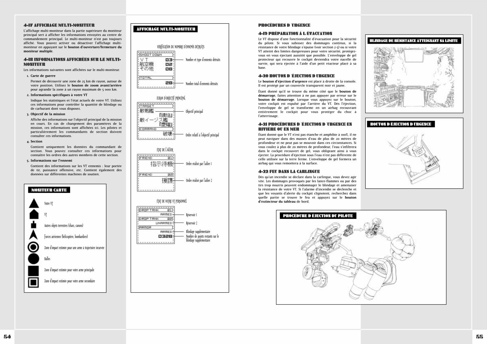
5554
4-17 AFFICHAGE MULTI-MONITEURL'affichage multi-moniteur dans la partie supérieure du moniteurprincipal sert à afficher les informations envoyées au centre decommandement principal. Le multi-moniteur n'est pas toujoursaffiché. Vous pouvez activer ou désactiver l'affichage multi-moniteur en appuyant sur le bouton d'ouverture/fermeture dumoniteur multiple.
4-18 INFORMATIONS AFFICHÉES SUR LE MULTI-MONITEURLes informations suivantes sont affichées sur le multi-moniteur.
1. Carte de guerre
Permet de découvrir une zone de 25 km de rayon, autour devotre position. Utilisez le bouton de zoom avant/arrièrepour agrandir la zone à un rayon maximum de 5 000 km.
2. Informations spécifiques à votre VT
Indique les statistiques et l'état actuels de votre VT. Utilisezces informations pour contrôler la quantité de blindage oude carburant dont vous disposez.
3. Objectif de la mission
Affiche des informations sur l'objectif principal de la missionen cours. En cas de changement des paramètres de lamission, ces informations sont affichées ici. Les pilotes etparticulièrement les commandants de section doiventconsulter ces informations.
4. Section
Contient uniquement les données du commandant desection. Vous pouvez consulter ces informations pourconnaître les ordres des autres membres de cette section.
5. Informations sur l'ennemi
Contient des informations sur les VT ennemis : leur portéede tir, puissance offensive, etc. Contient également desdonnées sur différentes machines de soutien.
Votre VT
VT
Autres objets terrestres (chars, canons)
Forces aériennes (hélicoptère, bombardiers)
Zone d'impact estimée pour une arme à trajectoire incurvée
Balles
Zone d'impact estimée pour votre arme principale
Zone d'impact estimée pour votre arme secondaire
MONITEUR CARTE
AFFICHAGE MULTI-MONITEUR
VÉRIFICATION DU NOMBRE D'ENNEMIS DÉTRUITS
Nombre et type d'ennemis détruits
Nombre total d'ennemis détruits
Objectif principal
Ordre relatif à l'objectif principal
ÉCRAN D'OBJECTIF PRINCIPAL
Ordre réalisé par l'ailier 1
Ordre réalisé par l'ailier 2
ÉTAT DE L'AILIER
Réservoir 1
Réservoir 2
Blindage supplémentaireNombre de points restants sur leblindage supplémentaire
ÉTAT DE VOTRE VT PERSONNEL
PROCÉDURES D ´URGENCE
4-19 PRÉPARATION À L ÉVACUATIONLe VT dispose d'une fonctionnalité d'évacuation pour la sécuritédu pilote. Si vous subissez des dommages continus, si larésistance de votre blindage s'épuise (voir section 2-5) ou si votreVT atteint des limites dangereuses pour votre sécurité, protégez-vous en vous éjectant aussitôt que possible. L'enveloppe de gelprotecteur qui recouvre le cockpit deviendra votre nacelle desurvie, qui sera éjectée à l'aide d'un petit réacteur placé à sabase.
4-20 BOUTON D ´ÉJECTION D URGENCELe bouton d'éjection d'urgence est placé à droite de la console.Il est protégé par un couvercle transparent noir et jaune.
Étant donné qu'il se trouve du même côté que le bouton dedémarrage, faites attention à ne pas appuyer par erreur sur lebouton de démarrage. Lorsque vous appuyez sur le bouton,votre cockpit est expulsé par l'arrière du VT. Dès l'éjection,l'enveloppe de gel se transforme en un airbag recouvrantentièrement le cockpit pour vous protéger du choc àl'atterrissage.
4-21 PROCÉDURES D ´ÉJECTION D ´URGENCE ENRIVIÈRE OU EN MERÉtant donné que le VT n'est pas étanche et amphibie à 100%, il nepeut naviguer dans des masses d'eau de plus de 20 mètres deprofondeur et ne peut pas se mouvoir dans ces circonstances. Sivous coulez à plus de 20 mètres de profondeur, l'eau s'infiltreradans le cockpit recouvert de gel, vous obligeant ainsi à vouséjecter. La procédure d'éjection sous l'eau n'est pas différente decelle utilisée sur la terre ferme. L'enveloppe de gel formera unairbag qui vous remontera à la surface.
4-22 FEU DANS LA CARLINGUEDès qu'un incendie se déclare dans la carlingue, vous devez agirvite. Les dommages provoqués par les lance-flammes ou par destirs trop nourris peuvent endommager le blindage et amenuiserla résistance de votre VT. Si l'alarme d'incendie se déclenche etque les voyants d'alerte du cockpit clignotent, recherchez dansquelle partie se trouve le feu et appuyez sur le boutond'extincteur du tableau de bord.
BOUTON D ÉJECTION D URGENCE
PROCÉDURE D ÉJECTION DU PILOTE
BLINDAGE DE RÉSISTANCE ATTEIGNANT SA LIMITE

5756
5-1 VISÉE ET TIRPour viser, placez le réticule de visée sur l'ennemi à l'écran àl'aide du stick de visée droit. Les armes du tronc sont libres deleurs mouvements et offrent un rayon de visée maximum de 180°au VT. Une fois que vous avez placé le curseur au-dessus del'ennemi, vous pouvez tirer avec votre arme principale ousecondaire en appuyant sur la gâchette de votre armeprincipale ou secondaire.
5-2 FONCTION DE VERROUILLAGEDans le VT, une fonctionnalité de verrouillage spéciale viseautomatiquement certains ennemis. Une fois que le réticule devisée commence à clignoter à l'écran, il vous suffit d'appuyer surle bouton de verrouillage du stick de visée droit pourverrouiller votre cible. Une fois le verrouillage activé, si vousappuyez sur la gâchette de votre arme principale ousecondaire, l'ennemi est automatiquement visé. Vous pouvezdésactiver le verrouillage en appuyant à nouveau sur le boutonde verrouillage une fois la cible ennemie détruite, ou disparuede l'écran.
Remarque : Étant donné que la fonction de verrouillage a étéessentiellement conçue contre les VT, vous ne pouvez pasverrouiller d'autres cibles que des VT ou des canons.
5-3 VISÉE EN COMBAT RAPPROCHÉParmi les armes secondaires du VT, on compte plusieurs armesde combat rapproché. Le chalumeau à plasma ALC205 en est unbon exemple car cette arme insolite ne peut servir que sur un VT.Vous devez toutefois faire attention. Si vous utilisez une de cesarmes, votre cible sera légèrement différente des ciblesnormales et vous passerez en mode de combat rapproché. Cemode de visée est utile pour le combat rapproché contre unennemi rapide immédiatement en face de vous. Le réticule nefonctionne que sur les objets placés directement en face devotre VT. Si vous appuyez sur le bouton d'arme secondaire alorsque l'ennemi est en face de vous, vous chargez et frappezl'ennemi avec votre chalumeau à plasma.
SECTION 5. ATTAQUE DU VT
DISTANCE DE VISÉE
RAYON DE VISÉE
180°
VISÉE D'ARME SECONDAIRE
Hors de portée de tir À portée de tir
VISÉE D'ARME PRINCIPALE
Hors de portée de tir À portée de tir
VERROUILLAGE
Verrouillage possible Post-verrouillage
CURSEURS EN MODES DE COMBAT NORMAL ETRAPPROCHÉ
Mode normal Mode rapproché
5-4 FSS (système de tir à estimation de cible)Le FSS est un système de tir conçu pour analyser les données decombat et les schémas de déplacement des VT ennemis.
Le bouton FSS du stick de visée vous permet passer du mode detir normal au mode de tir à estimation de cible, qui vous permetd'anticiper la prochaine position probable de l'ennemi. Pourrevenir au mode de tir normal, appuyez à nouveau sur le boutonFSS.
Remarque : Le FSS est une fonction de la deuxième génération dusystème d'exploitation. On ne la trouve donc pas sur les VT dotésdu système de première génération. Les données d'estimation surle schéma de déplacement de l'ennemi ne sont pas parfaites, etsi l'adversaire connaît bien le système, il peut procéder à desdéplacements que le FSS sera incapable d'anticiper. Le FSS seradonc inefficace face à certains adversaires.
5-5 PORTÉES DE TIR DES DIFFÉRENTESARMESChaque arme possède une portée de tir qui lui est propre. Lepilote doit assimiler les portées de tir maximale et effective dechacune des armes de son arsenal. La portée de tir effective dechaque arme est affichée à gauche ou à droite de la cible dumoniteur principal et est définie par le système de contrôled'artillerie.
La portée de tir de l'arme principale est affichée à droite duréticule. La portée de tir de l'arme secondaire est affichée àgauche. Les portées de tir des deux armes se superposent au-dessus du réticule. Si l'ennemi se met hors de portée, un messagevous en avertit.
5-6 NOTES SUR LE TIR À PORTÉE DE TIREFFECTIVELa portée de tir effective a été conçue essentiellement pours'afficher sur le moniteur principal. Toutefois, elle sertessentiellement en combat anti-VT. Lorsque vous affrontez unadversaire moins blindé que le VT (un char par exemple), il estprobable que vos tirs soient suffisamment puissants pouréliminer quelques ennemis, même hors de portée. Par ailleurs, laportée de tir effective est programmée en fonction de l'épaisseurdu blindage du VT, d'après les normes de la Pacific RimOrganization. Par conséquent, si une cible protégée par unblindage lourd se trouve à portée de tir effectif, il est possiblequ'elle ne soit pas endommagée par le tir. Faites attention.
AVEC LE CHALUMEAU À PLASMA
Mouvement très rapide
LIGNES DE TIR FSS
Position de la cible verrouillée au moment du tir
Position de la cible verrouillée au moment de l'impact du projectile
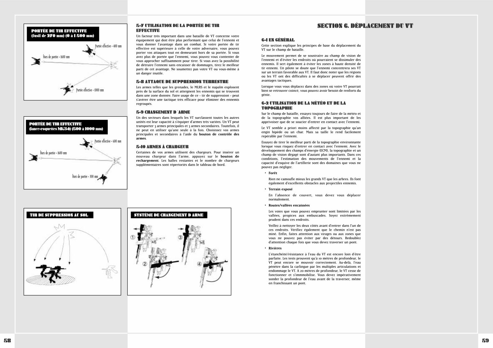
5958
5-7 UTILISATION DE LA PORTÉE DE TIREFFECTIVEUn facteur très important dans une bataille de VT concerne votreéquipement qui doit être plus performant que celui de l'ennemi etvous donner l'avantage dans un combat. Si votre portée de tireffective est supérieure à celle de votre adversaire, vous pouvezporter vos attaques tout en demeurant hors de sa portée. Si vousavez plus de portée que l'ennemi, vous pouvez vous contenter devous approcher suffisamment pour tirer. Si vous avez la possibilitéde détruire l'ennemi sans encaisser de dommages, tirez le meilleurparti de cet avantage. Ne soumettez pas votre VT ou vous-même àun danger inutile.
5-8 ATTAQUE DE SUPPRESSION TERRESTRELes armes telles que les grenades, le MLRS et le napalm explosentprès de la surface du sol et atteignent les ennemis qui se trouventdans une zone donnée. Faire usage de ce « tir de suppression » peuts'avérer être une tactique très efficace pour éliminer des ennemisregroupés.
5-9 CHANGEMENT D ´ARMEUn des secteurs dans lesquels les VT surclassent toutes les autresunités est leur capacité à s'équiper d'armes très variées. Un VT peuttransporter 3 armes principales et 3 armes secondaires. Toutefois, ilne peut en utiliser qu'une seule à la fois. Choisissez vos armesprincipales et secondaires à l'aide du bouton de contrôle desarmes.
5-10 ARMES À CHARGEURCertaines de vos armes utilisent des chargeurs. Pour insérer unnouveau chargeur dans l'arme, appuyez sur le bouton derechargement. Les balles restantes et le nombre de chargeurssupplémentaires sont répertoriés dans le tableau de bord.
SYSTÈME DE CHANGEMENT D ARMETIR DE SUPPRESSION AU SOL
Portée effective = 400 mm
Portée effective = 1000 mm
Hors de portée = 1600 mm
PORTÉE DE TIR EFFECTIVE (fusil de 270 mm) (0 à 1 500 mm)
PORTÉE DE TIR EFFECTIVE (lance-roquettes MK34) (500 à 1000 mm)
Portée effective = 600 mm
Hors de portée = 1600 mm
Hors de portée = 300 mm
6-1 EN GÉNÉRALCette section explique les principes de base du déplacement duVT sur le champ de bataille.
Le mouvement permet de se soustraire au champ de vision del'ennemi et d'éviter les endroits où pourraient se dissimuler desennemis. Il sert également à éviter les zones à haute densité detir ennemi. Un pilote se doute que l'ennemi concentrera ses VTsur un terrain favorable aux VT. Il faut donc noter que les régionsoù les VT ont des difficultés à se déplacer peuvent offrir desavantages tactiques.
Lorsque vous vous déplacez dans des zones où votre VT pourraitbien se retrouver coincé, vous pouvez avoir besoin de renforts dugénie.
6-2 UTILISATION DE LA MÉTÉO ET DE LATOPOGRAPHIESur le champ de bataille, essayez toujours de faire de la météo etde la topographie vos alliées. Il est plus important de lesapprivoiser que de se soucier d'entrer en contact avec l'ennemi.
Le VT semble a priori moins affecté par la topographie qu'unengin bipède ou un char. Mais sa taille le rend facilementrepérable par l'ennemi.
Essayez de tirer le meilleur parti de la topographie environnantelorsque vous risquez d'entrer en contact avec l'ennemi. Avec ledéveloppement des champs d'énergie (ECM), la topographie et unchamp de vision dégagé sont d'autant plus importants. Dans cesconditions, l'estimation des mouvements de l'ennemi et lacapacité d'esquive de l'artillerie sont des domaines que vous nepouvez pas négliger.
• Forêt
Rien ne camoufle mieux les grands VT que les arbres. Ils fontégalement d'excellents obstacles aux projectiles ennemis.
• Terrain exposé
En l'absence de couvert, vous devez vous déplacernormalement.
• Routes/vallées encaissées
Les voies que vous pouvez emprunter sont limitées par lesvallées, propices aux embuscades. Soyez extrêmementprudent dans ces endroits.
Veillez à nettoyer les deux côtés avant d'entrer dans l'un deces endroits. Vérifiez également que le chemin n'est pasminé. Enfin, faites attention aux virages ou aux zones quevous ne pouvez pas éviter par des détours. Redoublezd'attention chaque fois que vous devez traverser un pont.
• Rivières
L'étanchéité/résistance à l'eau du VT est encore loin d'êtreparfaite. Les tests prouvent qu'à 10 mètres de profondeur, leVT peut encore se mouvoir correctement. Au-delà, l'eaupénètre dans la carlingue par les multiples articulations etendommage le VT. À 20 mètres de profondeur, le VT cesse defonctionner et s'immmobilise. Vous devez impérativementsonder la profondeur de l'eau avant de la traverser, mêmeen franchissant un pont.
SECTION 6. DÉPLACEMENT DU VT
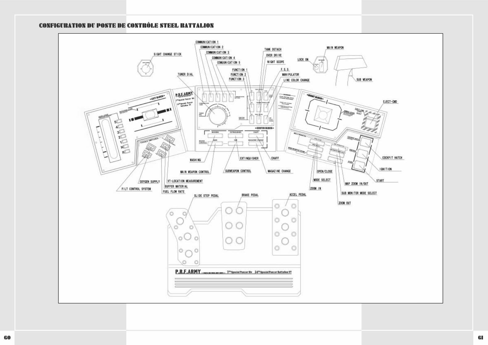
6160
CONFIGURATION DU POSTE DE CONTRÔLE STEEL BATTALION
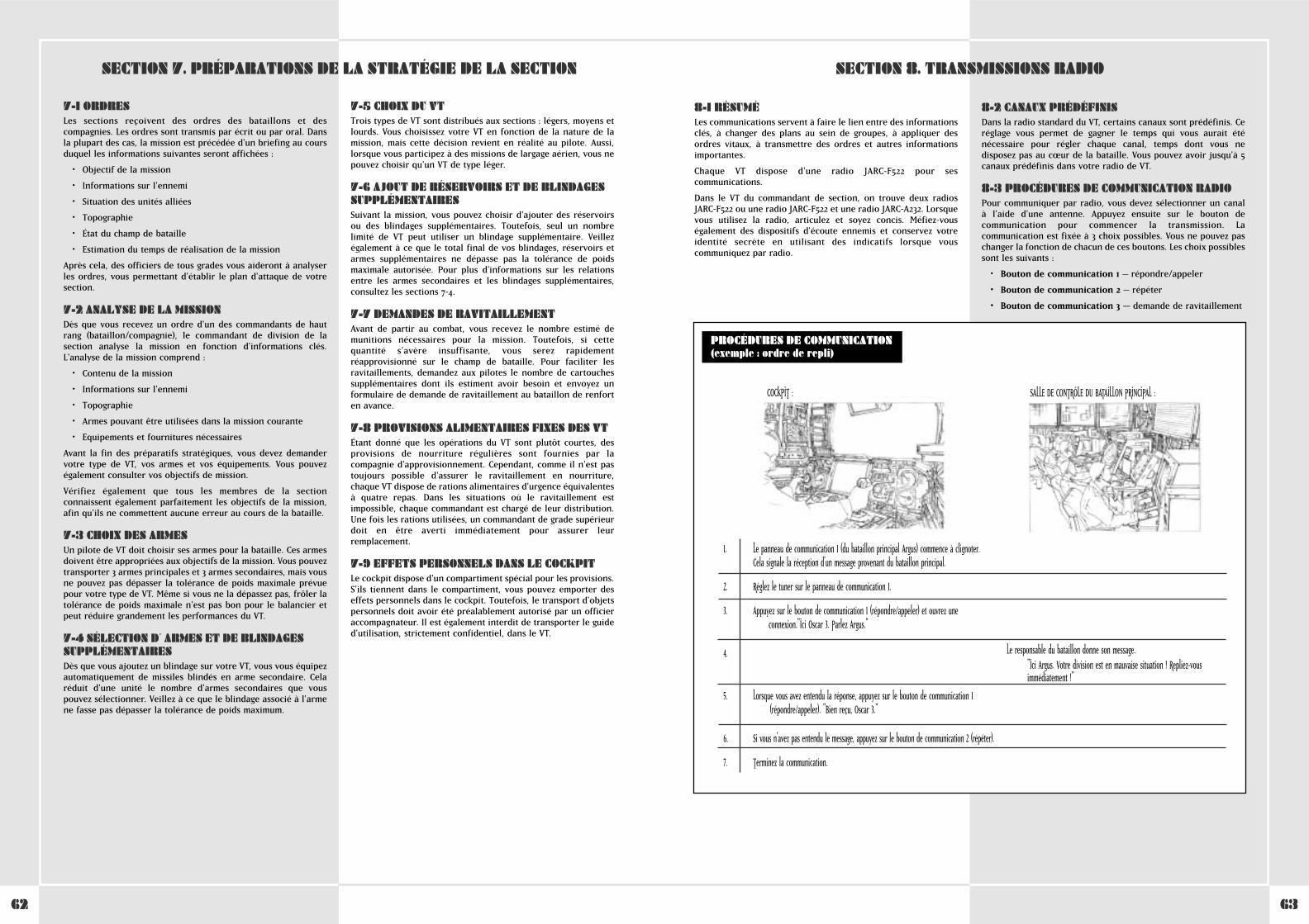
6362
8-1 RÉSUMÉLes communications servent à faire le lien entre des informationsclés, à changer des plans au sein de groupes, à appliquer desordres vitaux, à transmettre des ordres et autres informationsimportantes.
Chaque VT dispose d'une radio JARC-F522 pour sescommunications.
Dans le VT du commandant de section, on trouve deux radiosJARC-F522 ou une radio JARC-F522 et une radio JARC-A232. Lorsquevous utilisez la radio, articulez et soyez concis. Méfiez-vouségalement des dispositifs d'écoute ennemis et conservez votreidentité secrète en utilisant des indicatifs lorsque vouscommuniquez par radio.
8-2 CANAUX PRÉDÉFINISDans la radio standard du VT, certains canaux sont prédéfinis. Ceréglage vous permet de gagner le temps qui vous aurait éténécessaire pour régler chaque canal, temps dont vous nedisposez pas au cœur de la bataille. Vous pouvez avoir jusqu'à 5canaux prédéfinis dans votre radio de VT.
8-3 PROCÉDURES DE COMMUNICATION RADIOPour communiquer par radio, vous devez sélectionner un canal à l'aide d'une antenne. Appuyez ensuite sur le bouton decommunication pour commencer la transmission. Lacommunication est fixée à 3 choix possibles. Vous ne pouvez paschanger la fonction de chacun de ces boutons. Les choix possiblessont les suivants :
• Bouton de communication 1 – répondre/appeler
• Bouton de communication 2 – répéter
• Bouton de communication 3 – demande de ravitaillement
SECTION 8. TRANSMISSIONS RADIO
1. Communication panel 1 (from the main battalion Argus) begins to flash.This signals that a message from the main battalion is coming in.
2. Set the tuner on Communications Panel 1.
3. Press Communication Button 1 (respond/call) and open a connection.
"This is Oscar 3. Argus, go ahead."
Le responsable du bataillon donne son message."Ici Argus. Votre division est en mauvaise situation ! Repliez-vousimmédiatement !"
5. After you hear what was said, press Communication Button 1(respond/call).
"Oscar 3. I copy that."
6. Finish the communication.
PROCÉDURES DE COMMUNICATION(exemple : ordre de repli)
COCKPIT : SALLE DE CONTRÔLE DU BATAILLON PRINCIPAL :
1. Communication panel 1 (from the main battalion Argus) begins to flash.This signals that a message from the main battalion is coming in.
2. Set the tuner on Communications Panel 1.
3. Press Communication Button 1 (respond/call) and open a connection.
"This is Oscar 3. Argus, go ahead."
4. The battalion head gives his message.
"This is Argus. Your division is in a bad spot! Retreat immediately!"
5. After you hear what was said, press Communication Button 1 "
6. If you didn’t hear the message, press Communication Button 2 (repeat).
7. Finish the communication.
Le panneau de communication 1 (du bataillon principal Argus) commence à clignoter.Cela signale la réception d'un message provenant du bataillon principal.
Réglez le tuner sur le panneau de communication 1.
Appuyez sur le bouton de communication 1 (répondre/appeler) et ouvrez uneconnexion."Ici Oscar 3. Parlez Argus."
4. The battalion head gives his message.
"This is Argus. Your division is in a bad spot! Retreat immediately!"
Lorsque vous avez entendu la réponse, appuyez sur le bouton de communication 1(répondre/appeler). "Bien reçu, Oscar 3."
Si vous n'avez pas entendu le message, appuyez sur le bouton de communication 2 (répéter).
Terminez la communication.
7-1 ORDRESLes sections reçoivent des ordres des bataillons et descompagnies. Les ordres sont transmis par écrit ou par oral. Dansla plupart des cas, la mission est précédée d'un briefing au coursduquel les informations suivantes seront affichées :
• Objectif de la mission
• Informations sur l'ennemi
• Situation des unités alliées
• Topographie
• État du champ de bataille
• Estimation du temps de réalisation de la mission
Après cela, des officiers de tous grades vous aideront à analyserles ordres, vous permettant d'établir le plan d'attaque de votresection.
7-2 ANALYSE DE LA MISSIONDès que vous recevez un ordre d'un des commandants de hautrang (bataillon/compagnie), le commandant de division de lasection analyse la mission en fonction d'informations clés.L'analyse de la mission comprend :
• Contenu de la mission
• Informations sur l'ennemi
• Topographie
• Armes pouvant être utilisées dans la mission courante
• Equipements et fournitures nécessaires
Avant la fin des préparatifs stratégiques, vous devez demandervotre type de VT, vos armes et vos équipements. Vous pouvezégalement consulter vos objectifs de mission.
Vérifiez également que tous les membres de la sectionconnaissent également parfaitement les objectifs de la mission,afin qu'ils ne commettent aucune erreur au cours de la bataille.
7-3 CHOIX DES ARMESUn pilote de VT doit choisir ses armes pour la bataille. Ces armesdoivent être appropriées aux objectifs de la mission. Vous pouveztransporter 3 armes principales et 3 armes secondaires, mais vousne pouvez pas dépasser la tolérance de poids maximale prévuepour votre type de VT. Même si vous ne la dépassez pas, frôler latolérance de poids maximale n'est pas bon pour le balancier etpeut réduire grandement les performances du VT.
7-4 SÉLECTION D´ ARMES ET DE BLINDAGESSUPPLÉMENTAIRESDès que vous ajoutez un blindage sur votre VT, vous vous équipezautomatiquement de missiles blindés en arme secondaire. Celaréduit d'une unité le nombre d'armes secondaires que vouspouvez sélectionner. Veillez à ce que le blindage associé à l'armene fasse pas dépasser la tolérance de poids maximum.
7-5 CHOIX DU VTTrois types de VT sont distribués aux sections : légers, moyens etlourds. Vous choisissez votre VT en fonction de la nature de lamission, mais cette décision revient en réalité au pilote. Aussi,lorsque vous participez à des missions de largage aérien, vous nepouvez choisir qu'un VT de type léger.
7-6 AJOUT DE RÉSERVOIRS ET DE BLINDAGESSUPPLÉMENTAIRESSuivant la mission, vous pouvez choisir d'ajouter des réservoirsou des blindages supplémentaires. Toutefois, seul un nombrelimité de VT peut utiliser un blindage supplémentaire. Veillezégalement à ce que le total final de vos blindages, réservoirs etarmes supplémentaires ne dépasse pas la tolérance de poidsmaximale autorisée. Pour plus d'informations sur les relationsentre les armes secondaires et les blindages supplémentaires,consultez les sections 7-4.
7-7 DEMANDES DE RAVITAILLEMENTAvant de partir au combat, vous recevez le nombre estimé demunitions nécessaires pour la mission. Toutefois, si cettequantité s'avère insuffisante, vous serez rapidementréapprovisionné sur le champ de bataille. Pour faciliter lesravitaillements, demandez aux pilotes le nombre de cartouchessupplémentaires dont ils estiment avoir besoin et envoyez unformulaire de demande de ravitaillement au bataillon de renforten avance.
7-8 PROVISIONS ALIMENTAIRES FIXES DES VTÉtant donné que les opérations du VT sont plutôt courtes, desprovisions de nourriture régulières sont fournies par lacompagnie d'approvisionnement. Cependant, comme il n'est pastoujours possible d'assurer le ravitaillement en nourriture,chaque VT dispose de rations alimentaires d'urgence équivalentesà quatre repas. Dans les situations où le ravitaillement estimpossible, chaque commandant est chargé de leur distribution.Une fois les rations utilisées, un commandant de grade supérieurdoit en être averti immédiatement pour assurer leurremplacement.
7-9 EFFETS PERSONNELS DANS LE COCKPITLe cockpit dispose d'un compartiment spécial pour les provisions.S'ils tiennent dans le compartiment, vous pouvez emporter deseffets personnels dans le cockpit. Toutefois, le transport d'objetspersonnels doit avoir été préalablement autorisé par un officieraccompagnateur. Il est également interdit de transporter le guided'utilisation, strictement confidentiel, dans le VT.
SECTION 7. PRÉPARATIONS DE LA STRATÉGIE DE LA SECTION
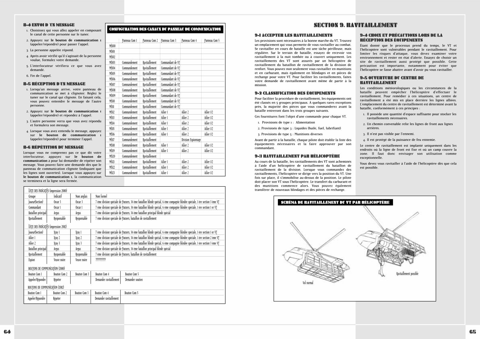
6564
9-1 ACCEPTER LES RAVITAILLEMENTSLes provisions sont nécessaires à la bonne marche du VT. Trouvezun emplacement qui vous permette de vous ravitailler au combat.Se ravitailler en cours de bataille est une tâche périlleuse, maisrégulière. Sur le terrain de bataille, essayez de recevoir vosravitaillement à la nuit tombée ou à couvert uniquement. Lesravitaillements des VT sont assurés par un hélicoptère deravitaillement du bataillon de ravitaillement de la division derenfort. Vous pouvez non seulement vous ravitailler en munitionset en carburant, mais également en blindages et en pièces derechange pour votre VT. Pour faciliter les ravitaillements, faitesvotre demande de ravitaillement avant même de partir à lamission.
9-2 CLASSIFICATION DES ÉQUIPEMENTSPour faciliter la procédure de ravitaillement, les équipements ontété classés en 5 groupes principaux. À quelques rares exceptionsprès, la majorité des pièces que vous commanderez avant labataille entreront dans les trois groupes suivants.
Ces fournitures font l'objet d'une commande pour chaque VT.
1. Provisions de type 1 : Alimentation
2. Provisions de type 3 : Liquides (huile, fuel, lubrifiant)
3. Provisions de type 5 : Munitions diverses
Avant de partir à la bataille, chaque pilote doit établir la liste deséquipements nécessaires et la faire approuver par soncommandant.
9-3 RAVITAILLEMENT PAR HÉLICOPTÈREAu cours de la bataille, les ravitaillements des VT sont acheminés à l'aide d'un hélicoptère de ravitaillement du bataillon deravitaillement de la division. Lorsque vous commandez desravitaillements, l'hélicoptère se dirige vers la position du VT. Unefois sur place, il s'immobilise au-dessus de la position. Le pilotedoit placer son VT sous l'hélicoptère. Le transfert du carburant etdes munitions commence alors. Vous pouvez égalementtransférer de nouveaux blindages et des pièces de rechange.
9-4 CHOIX ET PRÉCAUTIONS LORS DE LARÉCEPTION DES ÉQUIPEMENTSÉtant donné que le processus prend du temps, le VT etl'hélicoptère sont vulnérables pendant le ravitaillement. Pourlimiter les risques d'attaque, vous devez examiner votreenvironnement et rester en état d'alerte. Essayez de choisir unsite de ravitaillement aussi protégé que possible. Cetteprécaution est importante, notamment pour éviter quel'hélicoptère se fasse abattre avant d'avoir pu vous ravitailler.
9-5 OUVERTURE DU CENTRE DERAVITAILLEMENTLes conditions météorologiques ou les circonstances de labataille peuvent empêcher l'hélicoptère d'effectuer leravitaillement. Pour remédier à ces situations, un centre deravitaillement a été mis en place derrière les lignes alliées.L'emplacement du centre de ravitaillement est déterminé avant labataille, conformément à ces principes :
1. Il possède une quantité d'espace suffisante pour stocker les ravitaillements nécessaires.
2. Un chemin convenable relie les lignes de front aux lignes arrières.
3. Il n'est pas visible par l'ennemi.
4. Il est protégé de la puissance de feu ennemie.
Le centre de ravitaillement est implanté uniquement dans lesendroits où la ligne de front est fixe et où un camp couvre lazone. Il faut donc envisager son utilisation commeexceptionnelle.
Vous devez vous ravitailler à l'aide de l'hélicoptère dès que celaest possible.
SECTION 9. RAVITAILLEMENT
SCHÉMA DE RAVITAILLEMENT DU VT PAR HÉLICOPTÈRE
Vol normal
Ravitaillement possible
8-4 ENVOI D ´UN MESSAGE1. Choisissez qui vous allez appeler en composant
le canal de cette personne sur le tuner.
2. Appuyez sur le bouton de communication 1(appeler/répondre) pour passer l'appel.
3. La personne appelée répond.
4. Après avoir vérifié qu'il s'agissait de la personnevoulue, formulez votre demande.
5. L'interlocuteur vérifiera ce que vous avezdemandé.
6. Fin de l'appel.
8-5 RÉCEPTION D´UN MESSAGE1. Lorsqu'un message arrive, votre panneau de
communication se met à clignoter. Réglez letuner sur le canal qui clignote. En faisant cela,vous pouvez entendre le message de l'autrepersonne.
2. Appuyez sur le bouton de communication 1(appeler/répondre) et répondez à l'appel.
3. L'autre personne verra que vous avez réponduet formulera son message.
4. Lorsque vous avez entendu le message, appuyezsur le bouton de communication 1(appeler/répondre) pour terminer l'appel.
8-6 RÉPÉTITION DU MESSAGELorsque vous ne comprenez pas ce que dit votreinterlocuteur, appuyez sur le bouton decommunication 2 pour lui demander de répéter sonmessage. Vous pouvez faire une demande dès que lepanneau de communication clignote (indiquant queles lignes sont ouvertes). Lorsque vous appuyez surle bouton de communication 1, la communicationse terminera et la ligne sera fermée.
LISTE DES INDICATIFS (impression 2080)Groupe Indicatif Nom anglais Nom formelJoueur(Section) Oscar 3 Oscar 3 7 ème division spéciale de Panzers, 34 ème bataillon blindé spécial, 6 ème compagnie blindée spéciale, 1 ère section 3 ème VTCommandant Oscar 1 Oscar 1 7 ème division spéciale de Panzers, 34 ème bataillon blindé spécial, 6 ème compagnie blindée spéciale, 1 ère section 1 er VTBataillon principal Argus Argus 7 ème division spéciale de Panzers, 34 ème bataillon principal blindé spécialRavitaillement Responsable Responsable 7 ème division spéciale de Panzers, bataillon de ravitaillement
LISTE DES INDICATIFS (impression 2082)Joueur(Section) Xray 1 Xray 1 7 ème division spéciale de Panzers, 34 ème bataillon blindé spécial, 6 ème compagnie blindée spéciale, 1 ère section 1 er VTAilier 1 Xray 2 Xray 2 7 ème division spéciale de Panzers, 34 ème bataillon blindé spécial, 6 ème compagnie blindée spéciale, 1 ère section 2 ème VTAilier 2 Xray 3 Xray 3 7 ème division spéciale de Panzers, 34 ème bataillon blindé spécial, 6 ème compagnie blindée spéciale, 1 ère section 3 ème VTBataillon principal Argus Argus 7 ème division spéciale de Panzers, 34 ème bataillon principal blindé spécialRavitaillement Responsable Responsable 7 ème division spéciale de Panzers, bataillon de ravitaillementEspion Veuve noire Veuve noire ??????????
BOUTONS DE COMMUNICATION (2082)Bouton Com 1 Bouton Com 2 Bouton Com 3 Bouton Com 4 Bouton Com 5Appeler/Répondre Répéter Demander ravitaillement
BOUTONS DE COMMUNICATION (2080)Bouton Com 1 Bouton Com 2 Bouton Com 3 Bouton Com 4 Bouton Com 5Appeler/Répondre Répéter Demander ravitaillement Demander soutien
CONFIGURATION DES CANAUX DU PANNEAU DE COMMUNICATION
Panneau Com 1 Panneau Com 2 Panneau Com 3 Panneau Com 4 Panneau Com 5MIS00MIS01MIS02MIS03 Commandement Ravitaillement Commandant de VTMIS04 Commandement Ravitaillement Commandant de VTMIS05 Commandement Ravitaillement Commandant de VTMIS06 Commandement Ravitaillement Commandant de VTMIS07 Commandement Ravitaillement Commandant de VTMIS08 Commandement Ravitaillement Commandant de VTMIS09 Commandement Ravitaillement Commandant de VTMIS10 Commandement Ravitaillement Commandant de VTMIS11 Commandement Ravitaillement Commandant de VTMIS12 Commandement Ravitaillement Ailier 1 Ailier 2 Ailier 1/2MIS13 Commandement Ravitaillement Ailier 1 Ailier 2 Ailier 1/2MIS14 Commandement Ravitaillement Ailier 1 Ailier 2 Ailier 1/2MIS15 Commandement Ravitaillement Ailier 1 Ailier 2 Ailier 1/2MIS16 Commandement Ravitaillement Ailier 1 Ailier 2 Ailier 1/2MIS17 Commandement Ravitaillement Division EspionnageMIS18 Commandement Ravitaillement Ailier 1 Ailier 2 Ailier 1/2MIS19 Commandement Ravitaillement Ailier 1 Ailier 2 Ailier 1/2MIS20 Commandement RavitaillementMIS21 Commandement Ravitaillement Ailier 1 Ailier 2 Ailier 1/2MIS22 Commandement Ravitaillement Ailier 1 Ailier 2 Ailier 1/2MIS23 Commandement Ravitaillement Ailier 1 Ailier 2 Ailier 1/2
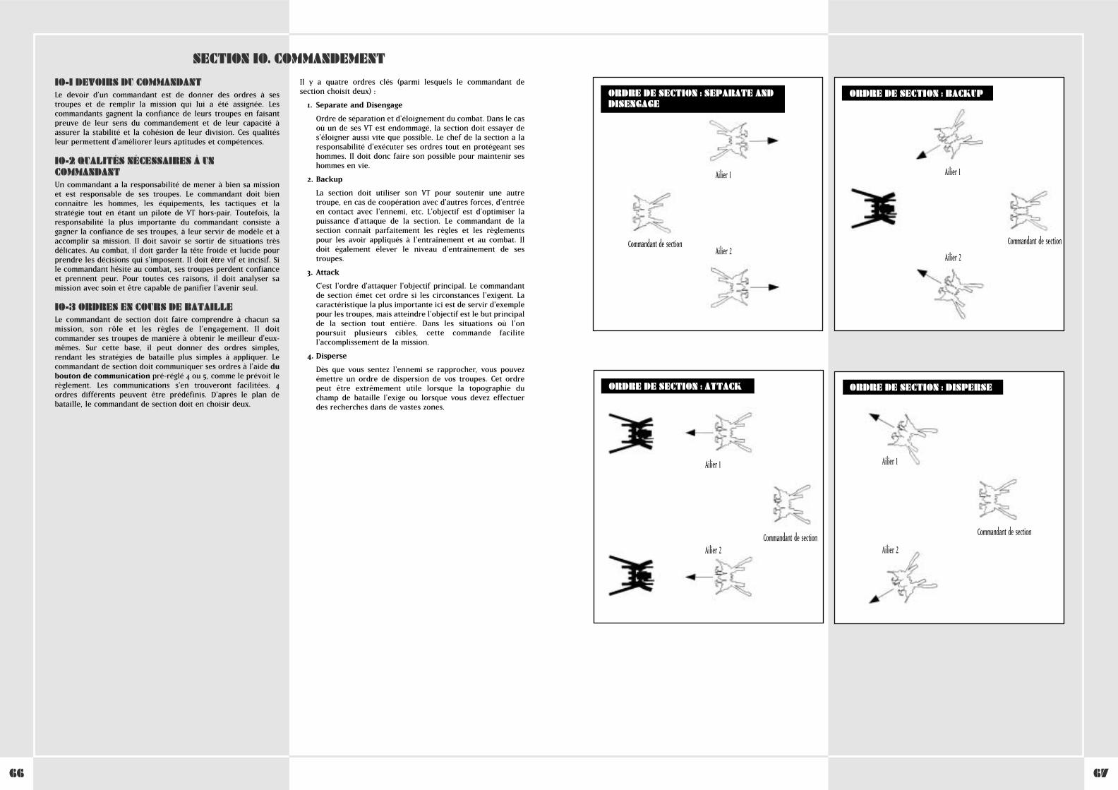
6766
10-1 DEVOIRS DU COMMANDANTLe devoir d'un commandant est de donner des ordres à sestroupes et de remplir la mission qui lui a été assignée. Lescommandants gagnent la confiance de leurs troupes en faisantpreuve de leur sens du commandement et de leur capacité àassurer la stabilité et la cohésion de leur division. Ces qualitésleur permettent d'améliorer leurs aptitudes et compétences.
10-2 QUALITÉS NÉCESSAIRES À UNCOMMANDANTUn commandant a la responsabilité de mener à bien sa missionet est responsable de ses troupes. Le commandant doit bienconnaître les hommes, les équipements, les tactiques et lastratégie tout en étant un pilote de VT hors-pair. Toutefois, laresponsabilité la plus importante du commandant consiste àgagner la confiance de ses troupes, à leur servir de modèle et àaccomplir sa mission. Il doit savoir se sortir de situations trèsdélicates. Au combat, il doit garder la tête froide et lucide pourprendre les décisions qui s'imposent. Il doit être vif et incisif. Sile commandant hésite au combat, ses troupes perdent confianceet prennent peur. Pour toutes ces raisons, il doit analyser samission avec soin et être capable de panifier l'avenir seul.
10-3 ORDRES EN COURS DE BATAILLELe commandant de section doit faire comprendre à chacun samission, son rôle et les règles de l'engagement. Il doitcommander ses troupes de manière à obtenir le meilleur d'eux-mêmes. Sur cette base, il peut donner des ordres simples,rendant les stratégies de bataille plus simples à appliquer. Lecommandant de section doit communiquer ses ordres à l'aide dubouton de communication pré-réglé 4 ou 5, comme le prévoit lerèglement. Les communications s'en trouveront facilitées. 4ordres différents peuvent être prédéfinis. D'après le plan debataille, le commandant de section doit en choisir deux.
Il y a quatre ordres clés (parmi lesquels le commandant desection choisit deux) :
1. Separate and Disengage
Ordre de séparation et d'éloignement du combat. Dans le casoù un de ses VT est endommagé, la section doit essayer des'éloigner aussi vite que possible. Le chef de la section a laresponsabilité d'exécuter ses ordres tout en protégeant seshommes. Il doit donc faire son possible pour maintenir seshommes en vie.
2. Backup
La section doit utiliser son VT pour soutenir une autretroupe, en cas de coopération avec d'autres forces, d'entréeen contact avec l'ennemi, etc. L'objectif est d'optimiser lapuissance d'attaque de la section. Le commandant de lasection connaît parfaitement les règles et les règlementspour les avoir appliqués à l'entraînement et au combat. Ildoit également élever le niveau d'entraînement de sestroupes.
3. Attack
C'est l'ordre d'attaquer l'objectif principal. Le commandantde section émet cet ordre si les circonstances l'exigent. Lacaractéristique la plus importante ici est de servir d'exemplepour les troupes, mais atteindre l'objectif est le but principalde la section tout entière. Dans les situations où l'onpoursuit plusieurs cibles, cette commande facilitel'accomplissement de la mission.
4. Disperse
Dès que vous sentez l'ennemi se rapprocher, vous pouvezémettre un ordre de dispersion de vos troupes. Cet ordrepeut être extrêmement utile lorsque la topographie duchamp de bataille l'exige ou lorsque vous devez effectuerdes recherches dans de vastes zones.
SECTION 10. COMMANDEMENT
WHEN USING THE PLASMA TORCH
ORDRE DE SECTION : SEPARATE ANDDISENGAGE
ORDRE DE SECTION : BACKUP
ORDRE DE SECTION : ATTACK ORDRE DE SECTION : DISPERSE
Ailier 1
Ailier 2Commandant de section
Ailier 1
Ailier 2
Commandant de section
Ailier 1
Ailier 2Commandant de section
Ailier 1
Ailier 2
Commandant de section
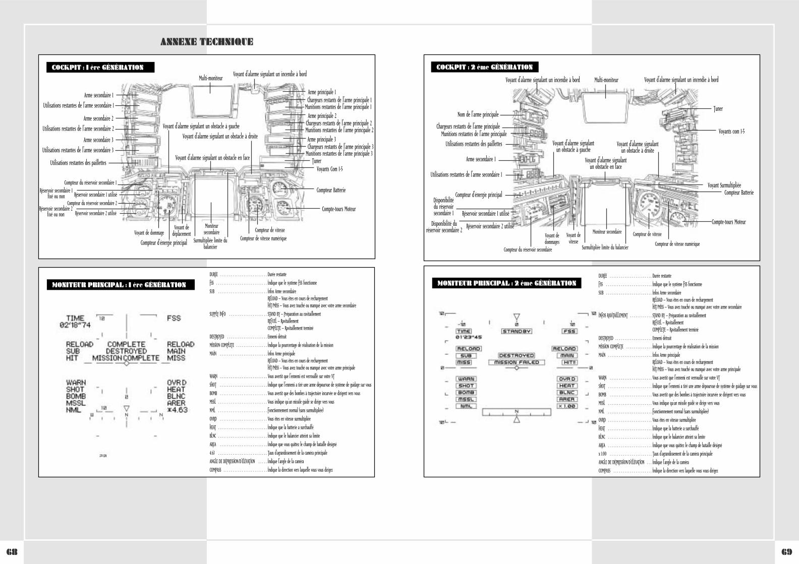
6968
WHEN USING THE PLASMA TORCH
ANNEXE TECHNIQUE
COCKPIT : 1 ère GÉNÉRATION
Voyant d'alarme signalant un obstacle en face
Multi-moniteur
Arme secondaire 1
Utilisations restantes de l'arme secondaire 1
Arme principale 1Chargeurs restants de l'arme principale 1
Munitions restantes de l'arme principale 1
Voyant d'alarme signalant un incendie à bord
Voyant d'alarme signalant un obstacle à droite
Voyant d'alarme signalant un obstacle à gauche
Arme principale 2Chargeurs restants de l'arme principale 2Munitions restantes de l'arme principale 2Arme principale 3Chargeurs restants de l'arme principale 3
Munitions restantes de l'arme principale 3
Voyants Com 1-5
Compteur Batterie
Compte-tours Moteur
Compteur de vitesse
Compteur d'énergie principal
Voyant de dommageMoniteur
secondaireVoyant de
déplacementCompteur de vitesse numériqueSurmultipliée limite du
balancier
Tuner
Arme secondaire 2
Utilisations restantes de l'arme secondaire 2
Compteur du réservoir secondaire 1Réservoir secondaire 1
fixé ou non Réservoir secondaire 1 utiliséCompteur du réservoir secondaire 2
Réservoir secondaire 2fixé ou non Réservoir secondaire 2 utilisé
Arme secondaire 3
Utilisations restantes de l'arme secondaire 3
Utilisations restantes des paillettes
WHEN USING THE PLASMA TORCHCOCKPIT : 2 ème GÉNÉRATION
Voyant d'alarme signalantun obstacle en face
Surmultipliée limite du balancier
Multi-moniteur
Nom de l'arme principale
Chargeurs restants de l'arme principaleMunitions restantes de l'arme principale
Voyant d'alarme signalant un incendie à bord Voyant d'alarme signalant un incendie à bord
Voyant d'alarme signalantun obstacle à droite
Voyant d'alarme signalant un obstacle à gauche
Voyants com 1-5
Compteur BatterieVoyant Surmultipliée
Compte-tours Moteur
Compteur de vitesse
Compteur d'énergie principal
Voyant dedommages
Moniteur secondaireVoyant devitesse Compteur de vitesse numérique
Tuner
Arme secondaire 1
Utilisations restantes de l'arme secondaire 1
Compteur du réservoir secondaire
Réservoir secondaire 1 utilisé
Disponibilité du réservoirsecondaire 1
Réservoir secondaire 2 utiliséDisponibilité duréservoir secondaire 2
Utilisations restantes des paillettes
MONITEUR PRINCIPAL : 2 ème GÉNÉRATIONDURÉE . . . . . . . . . . . . . . . . . . . . . . . Durée restante
FSS . . . . . . . . . . . . . . . . . . . . . . . . . Indique que le système FSS fonctionne
SUB . . . . . . . . . . . . . . . . . . . . . . . . . Infos Arme secondaireRELOAD – Vous êtes en cours de rechargementHIT/MISS – Vous avez touché ou manqué avec votre arme secondaire
INFOS RAVITAILLEMENT . . . . . . . . . . . . STAND BY – Préparation au ravitaillementREFUEL – RavitaillementCOMPLETE – Ravitaillement terminé
DESTROYED . . . . . . . . . . . . . . . . . . . . Ennemi détruit
MISSION COMPLETE . . . . . . . . . . . . . . Indique la pourcentage de réalisation de la mission
MAIN . . . . . . . . . . . . . . . . . . . . . . . . Infos Arme principaleRELOAD – Vous êtes en cours de rechargementHIT/MISS – Vous avez touché ou manqué avec votre arme principale
WARN . . . . . . . . . . . . . . . . . . . . . . . Vous avertit que l'ennemi est verrouillé sur votre VT
SHOT . . . . . . . . . . . . . . . . . . . . . . . . Indique que l'ennemi a tiré une arme dépourvue de système de guidage sur vous
BOMB . . . . . . . . . . . . . . . . . . . . . . . Vous avertit que des bombes à trajectoire incurvée se dirigent vers vous
MSSL . . . . . . . . . . . . . . . . . . . . . . . . Vous indique qu'un missile guidé se dirige vers vous
NML . . . . . . . . . . . . . . . . . . . . . . . . Fonctionnement normal (sans surmultipliée)
OVRD . . . . . . . . . . . . . . . . . . . . . . . . Vous êtes en vitesse surmultipliée
HEAT . . . . . . . . . . . . . . . . . . . . . . . . Indique que la batterie a surchauffé
BLNC . . . . . . . . . . . . . . . . . . . . . . . . Indique que le balancier atteint sa limite
AREA . . . . . . . . . . . . . . . . . . . . . . . . Indique que vous quittez le champ de bataille désigné
x 1.00 . . . . . . . . . . . . . . . . . . . . . . . Taux d'agrandissement de la caméra principale
ANGLE DE DÉPRESSION/D'ÉLÉVATION . . . Indique l'angle de la caméra
COMPASS . . . . . . . . . . . . . . . . . . . . . Indique la direction vers laquelle vous vous dirigez
MONITEUR PRINCIPAL : 1 ère GÉNÉRATION
DURÉE . . . . . . . . . . . . . . . . . . . . . . . . . . Durée restante
FSS . . . . . . . . . . . . . . . . . . . . . . . . . . . . Indique que le système FSS fonctionne
SUB . . . . . . . . . . . . . . . . . . . . . . . . . . . Infos Arme secondaireRELOAD – Vous êtes en cours de rechargementHIT/MISS – Vous avez touché ou manqué avec votre arme secondaire
SUPPLY INFO . . . . . . . . . . . . . . . . . . . . . STAND BY – Préparation au ravitaillementREFUEL – RavitaillementCOMPLETE – Ravitaillement terminé
DESTROYED . . . . . . . . . . . . . . . . . . . . . . Ennemi détruit
MISSION COMPLETE . . . . . . . . . . . . . . . . . Indique la pourcentage de réalisation de la mission
MAIN . . . . . . . . . . . . . . . . . . . . . . . . . . Infos Arme principaleRELOAD – Vous êtes en cours de rechargementHIT/MISS – Vous avez touché ou manqué avec votre arme principale
WARN . . . . . . . . . . . . . . . . . . . . . . . . . . Vous avertit que l'ennemi est verrouillé sur votre VT
SHOT . . . . . . . . . . . . . . . . . . . . . . . . . . Indique que l'ennemi a tiré une arme dépourvue de système de guidage sur vous
BOMB . . . . . . . . . . . . . . . . . . . . . . . . . . Vous avertit que des bombes à trajectoire incurvée se dirigent vers vous
MSSL . . . . . . . . . . . . . . . . . . . . . . . . . . . Vous indique qu'un missile guidé se dirige vers vous
NML . . . . . . . . . . . . . . . . . . . . . . . . . . . Fonctionnement normal (sans surmultipliée)
OVRD . . . . . . . . . . . . . . . . . . . . . . . . . . Vous êtes en vitesse surmultipliée
HEAT . . . . . . . . . . . . . . . . . . . . . . . . . . . Indique que la batterie a surchauffé
BLNC . . . . . . . . . . . . . . . . . . . . . . . . . . . Indique que le balancier atteint sa limite
AREA . . . . . . . . . . . . . . . . . . . . . . . . . . Indique que vous quittez le champ de bataille désigné
4.63 . . . . . . . . . . . . . . . . . . . . . . . . . . . Taux d'agrandissement de la caméra principale
ANGLE DE DÉPRESSION/D'ÉLÉVATION . . . . . Indique l'angle de la caméra
COMPASS . . . . . . . . . . . . . . . . . . . . . . . . Indique la direction vers laquelle vous vous dirigez
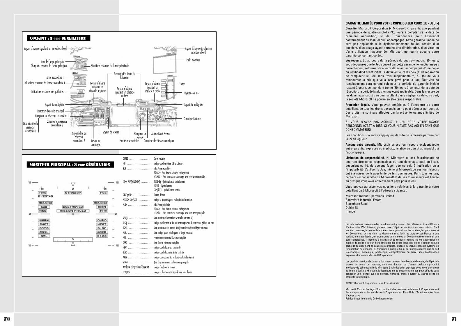
7170
GARANTIE LIMITÉE POUR VOTRE COPIE DU JEU XBOX (LE « JEU »)Garantie. Microsoft Corporation (« Microsoft ») garantit que pendantune période de quatre-vingt-dix (90) jours à compter de la date depremière acquisition, le Jeu fonctionnera pour l’essentielconformément au manuel qui l’accompagne. Cette garantie limitée nesera pas applicable si le dysfonctionnement du Jeu résulte d'unaccident, d’un usage ayant entraîné une détérioration, d’un virus oud’une utilisation inappropriée. Microsoft ne fournit aucune autregarantie concernant ce Jeu.Vos recours. Si, au cours de la période de quatre-vingt-dix (90) jours,vous découvrez que le Jeu couvert par cette garantie ne fonctionne pascorrectement, retournez-le à votre détaillant accompagné d’une copiedu justificatif d’achat initial. Le détaillant aura le choix (a) de réparer oude remplacer le Jeu sans frais supplémentaire, ou (b) de vousrembourser le prix que vous avez payé pour le Jeu. Tout Jeu deremplacement sera garanti soit pour la période de garantie initialerestant à courir, soit pendant trente (30) jours à compter de la date deréception, la période la plus longue étant applicable. Dans la mesure oùles dommages causés au Jeu résultent d’une négligence de votre part,la société Microsoft ne pourra en être tenue responsable.
Protection légale. Vous pouvez bénéficier, à l’encontre de votredétaillant, de tous les droits auxquels on ne peut déroger par contrat.Ces droits ne sont pas affectés par la présente garantie limitée deMicrosoft.
SI VOUS N’AVEZ PAS ACQUIS LE JEU POUR VOTRE USAGEPERSONNEL (C’EST À DIRE, SI VOUS N’AVEZ PAS AGI EN TANT QUECONSOMMATEUR)
Les conditions suivantes s’appliquent dans toute la mesure permise parla loi en vigueur.
Aucune autre garantie. Microsoft et ses fournisseurs excluent touteautre garantie, expresse ou implicite, relative au Jeu et au manuel quil’accompagne.
Limitation de responsabilité. Ni Microsoft ni ses fournisseurs nepourront être tenus responsables de tout dommage, quel qu’il soit,découlant ou lié, de quelque façon que ce soit, à l’utilisation ou àl’impossibilité d’utiliser le Jeu, même si Microsoft ou ses fournisseursont été avisés de la possibilité de tels dommages. Dans tous les cas,l’entière responsabilité de Microsoft et de ses fournisseurs est limitéeau prix que vous avez effectivement payé pour le Jeu.
Vous pouvez adresser vos questions relatives à la garantie à votredétaillant ou à Microsoft à l’adresse suivante :
Microsoft Ireland Operations LimitedSandyford Industrial EstateBlackthorn RoadDublin 18Irlande
Les informations contenues dans ce document, y compris les références à des URL ou àd'autres sites Web Internet, peuvent faire l'objet de modifications sans préavis. Saufmention contraire, les noms de sociétés, les organisations, les produits, les personnes etles événements décrits dans ce document sont fictifs et toute ressemblance à unesociété, une organisation, un produit, une personne ou un événement réels ne serait quepure coïncidence. Il incombe à l'utilisateur de respecter toutes les lois applicables enmatière de droits d'auteur. Sans limitation des droits issus des droits d'auteur, aucunepartie de ce document ne peut être reproduite, stockée ou incluse dans un système derécupération de données, ou transmise à quelque fin ou par quelque moyen que ce soit(électronique, mécanique, photocopie, enregistrement ou autre) sans l'autorisationexpresse et écrite de Microsoft Corporation.
Les produits mentionnés dans ce document peuvent faire l'objet de brevets, de dépôts debrevets en cours, de marques, de droits d'auteur ou d'autres droits de propriétéintellectuelle et industrielle de Microsoft. Sauf stipulation expresse contraire d'un contratde licence écrit de Microsoft, la fourniture de ce document n'a pas pour effet de vousconcéder une licence sur ces brevets, marques, droits d'auteur ou autres droits depropriété intellectuelle.
© 2003 Microsoft Corporation. Tous droits réservés.
Microsoft, Xbox et les logos Xbox sont soit des marques de Microsoft Corporation, soitdes marques déposées de Microsoft Corporation aux États-Unis d’Amérique et/ou dansd'autres pays. Fabriqué sous licence de Dolby Laboratories.
WHEN USING THE PLASMA TORCHCOCKPIT : 3 ème GÉNÉRATION
Voyant d'alarmesignalant un obstacle
en face
Surmultipliée limite dubalancier
Multi-moniteurNom de l'arme principaleChargeurs restants de l'arme principale Munitions restantes de l'arme principale
Voyant d'alarme signalant un incendie à bord Voyant d'alarme signalant unincendie à bord
Voyant d'alarmesignalant un
obstacle à droite
Voyant d'alarmesignalant un
obstacle à gaucheVoyants com 1-5
Compteur Batterie
Voyant SurmultipliéeVoyant Surmultipliée
Compte-tours MoteurCompteur devitesse
Compteur d'énergie principal
Voyant dedommages
Moniteur secondaire
Voyant de vitesse
Compteur de vitesse numériquer
Tuner
Arme secondaire 1Utilisations restantes de l'arme secondaire 1
Compteur du réservoir secondaire 1
Disponibilité duréservoir
secondaire 1
Compteur du réservoirsecondaire 2
Disponibilité duréservoir
secondaire 2
Utilisations restantes des paillettes
MONITEUR PRINCIPAL : 3 ème GÉNÉRATION
DURÉE . . . . . . . . . . . . . . . . . . . . . . . Durée restante
FSS . . . . . . . . . . . . . . . . . . . . . . . . . Indique que le système FSS fonctionne
SUB . . . . . . . . . . . . . . . . . . . . . . . . . Infos Arme secondaireRELOAD – Vous êtes en cours de rechargementHIT/MISS – Vous avez touché ou manqué avec votre arme secondaire
INFOS RAVITAILLEMENT . . . . . . . . . . . . STAND BY – Préparation au ravitaillementREFUEL – RavitaillementCOMPLETE – Ravitaillement terminé
DESTROYED . . . . . . . . . . . . . . . . . . . Ennemi détruit
MISSION COMPLETE . . . . . . . . . . . . . . Indique la pourcentage de réalisation de la mission
MAIN . . . . . . . . . . . . . . . . . . . . . . . . Infos Arme principaleRELOAD – Vous êtes en cours de rechargementHIT/MISS – Vous avez touché ou manqué avec votre arme principale
WARN . . . . . . . . . . . . . . . . . . . . . . . Vous avertit que l'ennemi est verrouillé sur votre VT
SHOT . . . . . . . . . . . . . . . . . . . . . . . . Indique que l'ennemi a tiré une arme dépourvue de système de guidage sur vous
BOMB . . . . . . . . . . . . . . . . . . . . . . . Vous avertit que des bombes à trajectoire incurvée se dirigent vers vous
MSSL . . . . . . . . . . . . . . . . . . . . . . . . Vous indique qu'un missile guidé se dirige vers vous
NML . . . . . . . . . . . . . . . . . . . . . . . . Fonctionnement normal (sans surmultipliée)
OVRD . . . . . . . . . . . . . . . . . . . . . . . Vous êtes en vitesse surmultipliée
HEAT . . . . . . . . . . . . . . . . . . . . . . . . Indique que la batterie a surchauffé
BLNC . . . . . . . . . . . . . . . . . . . . . . . . Indique que le balancier atteint sa limite
AREA . . . . . . . . . . . . . . . . . . . . . . . . Indique que vous quittez le champ de bataille désigné
x 1.00 . . . . . . . . . . . . . . . . . . . . . . . Taux d'agrandissement de la caméra principale
ANGLE DE DÉPRESSION/D'ÉLÉVATION . . . Indique l'angle de la caméra
COMPASS . . . . . . . . . . . . . . . . . . . . . Indique la direction vers laquelle vous vous dirigez
CONTROLLER-EINSTELLUNG . . . . . . . . . . . . . . . . . . . . . . . . . . . . . . . . . . . 74
Vorsichtsmaßnahmen . . . . . . . . . . . . . . . . . . . . . . . . . . . . . . . . . . . 74
Problembehandlung . . . . . . . . . . . . . . . . . . . . . . . . . . . . . . . . . . . . 74
Montage der rechten Einheit . . . . . . . . . . . . . . . . . . . . . . . . . . . . . . 74
Montage der linken Einheit . . . . . . . . . . . . . . . . . . . . . . . . . . . . . . . 74
ABSCHNITT 1. VT-KONZEPT UND SPEZIALPANZERDIVISION . . . . . . . . . . . . 76
1-1 VT-Konzept . . . . . . . . . . . . . . . . . . . . . . . . . . . . . . . . . . . . . . . . . 76
1-2 Grundlagen für den militärischen Einsatz des VT . . . . . . . . . . . . 76
1-3 Pflichten einer Spezialpanzereinheit . . . . . . . . . . . . . . . . . . . . . 76
1-4 Zusammensetzung einer Spezialpanzerdivision . . . . . . . . . . . . . 76
1-5 VT Platoon-Einsatz . . . . . . . . . . . . . . . . . . . . . . . . . . . . . . . . . . . 76
ABSCHNITT 2. VT-ZUSAMMENFASSUNG . . . . . . . . . . . . . . . . . . . . . . . . . . . 77
2-1 VT-Basisteile . . . . . . . . . . . . . . . . . . . . . . . . . . . . . . . . . . . . . . . . 77
2-2 VT-Betriebssystem . . . . . . . . . . . . . . . . . . . . . . . . . . . . . . . . . . . 77
2-3 VT-Typen . . . . . . . . . . . . . . . . . . . . . . . . . . . . . . . . . . . . . . . . . . 78
2-4 Bewegung . . . . . . . . . . . . . . . . . . . . . . . . . . . . . . . . . . . . . . . . . . 78
2-5 Kraftstofftank und Ersatztanks . . . . . . . . . . . . . . . . . . . . . . . . . 78
2-6 Kraftstoffverbrauch und geschätzte Einsatzdauer . . . . . . . . . . . 78
2-7 Schutzpanzerung . . . . . . . . . . . . . . . . . . . . . . . . . . . . . . . . . . . . 78
2-8 Hauptwaffen und Unterwaffen . . . . . . . . . . . . . . . . . . . . . . . . . 78
2-9 Maximal zulässiges Waffengewicht . . . . . . . . . . . . . . . . . . . . . . 78
2-10 Waffenarsenal des VT . . . . . . . . . . . . . . . . . . . . . . . . . . . . . . . 79
2-11 Zielausrichtung von Waffen mit gekrümmten Geschossflugbahnen auf der Kriegskarte . . . . . . . . . . . . . . . . . 80
2-12 Kurzzünder . . . . . . . . . . . . . . . . . . . . . . . . . . . . . . . . . . . . . . . 80
2-13 Verteidigung mithilfe von Düppeln . . . . . . . . . . . . . . . . . . . . . . 80
ABSCHNITT 3. SONDERFUNKTIONEN
DURCH COOS DER 2. GENERATION . . . . . . . . . . . . . . . . . . . . . . . . . . . . . . 84
3-1 Zusätze für COOS der 2. Generation . . . . . . . . . . . . . . . . . . . . . . 84
3-2 FSS-Funktion (Zielabschätzendes Feuersystem) . . . . . . . . . . . . . 84
3-3 Overdrive-Funktion . . . . . . . . . . . . . . . . . . . . . . . . . . . . . . . . . . 84
3-4 Tarnfunktion . . . . . . . . . . . . . . . . . . . . . . . . . . . . . . . . . . . . . . . 84
3-5 Lenkwaffen . . . . . . . . . . . . . . . . . . . . . . . . . . . . . . . . . . . . . . . . 84
ABSCHNITT 4. VT-STEUERUNGEN . . . . . . . . . . . . . . . . . . . . . . . . . . . . . . . 85
4-1 Startsequenz . . . . . . . . . . . . . . . . . . . . . . . . . . . . . . . . . . . . . . . 85
4-2 Anhalten des VT während des Starts . . . . . . . . . . . . . . . . . . . . . 85
Basissteuerungen . . . . . . . . . . . . . . . . . . . . . . . . . . . . . . . . . . . . . . 86
4-3 Bewegen und Anhalten . . . . . . . . . . . . . . . . . . . . . . . . . . . . . . . 86
4-4 Beschleunigen und Bremsen . . . . . . . . . . . . . . . . . . . . . . . . . . . 86
4-5 Drehung . . . . . . . . . . . . . . . . . . . . . . . . . . . . . . . . . . . . . . . . . . 86
4-6 Overdrive . . . . . . . . . . . . . . . . . . . . . . . . . . . . . . . . . . . . . . . . . 86
4-7 Gleitschrittfunktion . . . . . . . . . . . . . . . . . . . . . . . . . . . . . . . . . 86
4-8 Gleitschritt-Funktionseinschränkungen . . . . . . . . . . . . . . . . . . . 86
4-9 Gleitschritt-Kippstabilisator . . . . . . . . . . . . . . . . . . . . . . . . . . . 86
4-10 Abschaltfunktion . . . . . . . . . . . . . . . . . . . . . . . . . . . . . . . . . . . 86
4-11 Manipulator-Steuerungen . . . . . . . . . . . . . . . . . . . . . . . . . . . . . 87
VT-Monitor . . . . . . . . . . . . . . . . . . . . . . . . . . . . . . . . . . . . . . . . . . . 88
4-12 Hauptkamerawechsel . . . . . . . . . . . . . . . . . . . . . . . . . . . . . . . . 88
4-13 Hauptkamera Schmutz und Staub . . . . . . . . . . . . . . . . . . . . . . . 88
4-14 Sub-Monitor-Funktionen . . . . . . . . . . . . . . . . . . . . . . . . . . . . . 89
4-15 Nachtsichtausrüstung . . . . . . . . . . . . . . . . . . . . . . . . . . . . . . . . 89
JCS (Vollständiges Befehlssystem) . . . . . . . . . . . . . . . . . . . . . . . . . . 89
4-16 JCS Zusammenfassung . . . . . . . . . . . . . . . . . . . . . . . . . . . . . . . 89
4-17 Mehrfachmonitordarstellung . . . . . . . . . . . . . . . . . . . . . . . . . . 90
4-18 Auf dem Mehrfachmonitor dargestellte Informationen . . . . . . 90
Massnahmen in Notfall . . . . . . . . . . . . . . . . . . . . . . . . . . . . . . . . . . . . . . . 91
4-19 Evakuierungsvorbereitungen . . . . . . . . . . . . . . . . . . . . . . . . . . 91
4-20 Abspreng-Notschalter . . . . . . . . . . . . . . . . . . . . . . . . . . . . . . . 91
4-21 Vorgehensweisen bei der Notrettung auf Flüssen und Seen . . . 91
4-22 Feuer im Rumpf . . . . . . . . . . . . . . . . . . . . . . . . . . . . . . . . . . . . 91
ABSCHNITT 5. VT-ANGRIFF . . . . . . . . . . . . . . . . . . . . . . . . . . . . . . . . . . . . 92
5-1 Zielen und Schießen mit den Waffen . . . . . . . . . . . . . . . . . . . . . 92
5-2 Zielerfassungsfunktion . . . . . . . . . . . . . . . . . . . . . . . . . . . . . . . 92
5-3 Zielen im Nahkampf . . . . . . . . . . . . . . . . . . . . . . . . . . . . . . . . . 92
5-4 FSS (Zielabschätzendes Feuersystem) . . . . . . . . . . . . . . . . . . . . . 93
5-5 Schussweiten der verschiedenen Waffen . . . . . . . . . . . . . . . . . . 93
5-6 Hinweise zum Feuern innerhalb der effektiven Zieldistanz . . . . 93
5-7 Ausnutzung der effektiven Zieldistanz . . . . . . . . . . . . . . . . . . . . 94
5-8 Bodenabwehrangriff . . . . . . . . . . . . . . . . . . . . . . . . . . . . . . . . . 94
5-9 Wechsel der Waffe . . . . . . . . . . . . . . . . . . . . . . . . . . . . . . . . . . 94
5-10 Nachladen der Magazinwaffen . . . . . . . . . . . . . . . . . . . . . . . . . 94
ABSCHNITT 6. VT-BEWEGUNGEN . . . . . . . . . . . . . . . . . . . . . . . . . . . . . . . 95
6-1 Allgemeines . . . . . . . . . . . . . . . . . . . . . . . . . . . . . . . . . . . . . . . . 95
6-2 Ausnutzung von Wetter und Topografie . . . . . . . . . . . . . . . . . . 95
STEEL BATTALION-CONTROLLER-KONFIGURATION . . . . . . . . . . . . . . . . . . 96
ABSCHNITT 7. PLATOON-STRATEGIEVORBEREITUNGEN . . . . . . . . . . . . . . . 98
7-1 Befehle . . . . . . . . . . . . . . . . . . . . . . . . . . . . . . . . . . . . . . . . . . . 98
7-2 Missionsanalyse . . . . . . . . . . . . . . . . . . . . . . . . . . . . . . . . . . . . 98
7-3 Auswahl der Waffen . . . . . . . . . . . . . . . . . . . . . . . . . . . . . . . . . 98
7-4 Auswahl zusätzlicher Panzerungen und Unterwaffen . . . . . . . . . 98
7-5 Auswahl des VT . . . . . . . . . . . . . . . . . . . . . . . . . . . . . . . . . . . . . 98
7-6 Anbringen zusätzlicher Kraftstofftanks und Panzerungen . . . . . 98
7-7 Nachschubanforderungen . . . . . . . . . . . . . . . . . . . . . . . . . . . . . 98
7-8 Festgelegter VT-Lebensmittelproviant . . . . . . . . . . . . . . . . . . . . 98
7-9 Mitnahme von persönlicher Habe in das Cockpit . . . . . . . . . . . 98
ABSCHNITT 8. FUNKVERKEHR
8-1 Zusammenfassung . . . . . . . . . . . . . . . . . . . . . . . . . . . . . . . . . . . 99
8-2 Voreingestellte Kanäle . . . . . . . . . . . . . . . . . . . . . . . . . . . . . . . 99
8-3 Abläufe im Funkverkehr . . . . . . . . . . . . . . . . . . . . . . . . . . . . . . 99
8-4 Senden einer Meldung . . . . . . . . . . . . . . . . . . . . . . . . . . . . . . 100
8-5 Empfangen einer Meldung . . . . . . . . . . . . . . . . . . . . . . . . . . . . 100
8-6 Wiederholen der Meldung . . . . . . . . . . . . . . . . . . . . . . . . . . . 100
ABSCHNITT 9. NACHSCHUB . . . . . . . . . . . . . . . . . . . . . . . . . . . . . . . . . . . 101
9-1 Aufnahme von Nachschub . . . . . . . . . . . . . . . . . . . . . . . . . . . . . 101
9-2 Klassifizierung von Nachschub . . . . . . . . . . . . . . . . . . . . . . . . . 101
9-3 Nachschub per Versorgungshubschrauber . . . . . . . . . . . . . . . . 101
9-4 Möglichkeiten und Vorsichtsmaßnahmen bei der Aufnahme von Nachschub . . . . . . . . . . . . . . . . . . . . . . 101
9-5 Errichtung des Nachschubverteilungszentrums . . . . . . . . . . . . . 101
ABSCHNITT 10. FÜHRUNG . . . . . . . . . . . . . . . . . . . . . . . . . . . . . . . . . . . . 102
10-1 Führungspflichten . . . . . . . . . . . . . . . . . . . . . . . . . . . . . . . . . . 102
10-2 Erforderliche Qualitäten eines Commanders . . . . . . . . . . . . . . 102
10-3 Befehlserteilung während des Kampfes . . . . . . . . . . . . . . . . . 102
TECHNISCHER ANHANG . . . . . . . . . . . . . . . . . . . . . . . . . . . . . . . . . . . . . . 104
Cockpit: 1. Generation . . . . . . . . . . . . . . . . . . . . . . . . . . . . . . . . . . 104
Hauptmonitordarstellung: 1. Generation . . . . . . . . . . . . . . . . . . . . 104
Cockpit: 2. Generation . . . . . . . . . . . . . . . . . . . . . . . . . . . . . . . . . . 105
Hauptmonitordarstellung: 2. Generation . . . . . . . . . . . . . . . . . . . . 105
Cockpit: 3. Generation . . . . . . . . . . . . . . . . . . . . . . . . . . . . . . . . . . 106
Hauptmonitordarstellung: 3. Generation . . . . . . . . . . . . . . . . . . . . 106
Garantie . . . . . . . . . . . . . . . . . . . . . . . . . . . . . . . . . . . . . . . . . . . . 107
Support . . . . . . . . . . . . . . . . . . . . . . . . . . . . . . . . . . . . . . . . . . . . . 181
DEUTSCHSPIELVORBEREITUNGVielen Dank, dass Sie STEEL BATTALION erworben haben. LesenSie bitte vor Spielbeginn alle Benutzerhandbücher sorgfältigdurch. Nachdem Sie alle Benutzerhandbücher sorgfältigdurchgelesen haben, bewahren Sie sie griffbereit auf, um inZweifelsfällen nachsehen zu können.
WARNHINWEISE• Bewahren Sie das Gerät und sämtliche Komponenten für
Kinder unzugänglich auf.
• Öffnen Sie nicht das Gerät oder dazugehörige Komponenten.
• Das Gerät oder die dazugehörigen Komponenten dürfennicht mit Wasser in Berührung kommen.
• Bewahren Sie das Gerät und die dazugehörigenKomponenten an einem trockenen, staubfreien Ort auf.
• Unterbrechen Sie sofort den Betrieb, falls Problemeauftreten.
INHALT
7372
SICHERHEITSINFORMATIONENPhotosensitive Anfälle(Anfälle durch Lichtempfindlichkeit)Bei einer sehr kleinen Anzahl von Personen können bestimmtevisuelle Einflüsse (beispielsweise aufflackernde Lichter odervisuelle Muster, wie sie in Videospielen vorkommen) zuphotosensitiven Anfällen führen. Diese können auch bei Personenauftreten, in deren Krankheitsgeschichte keine Anzeichen fürEpilepsie o. Ä. vorhanden sind, bei denen jedoch ein nichtdiagnostizierter medizinischer Sachverhalt vorliegt, der diese sogenannten “photosensitiven epileptischen Anfälle” während desSpielens von Videospielen hervorrufen kann.
Derartige Anfälle können mit verschiedenen Symptomeneinhergehen, z. B. Schwindel, Veränderungen in der Sehleistung,Zuckungen im Auge oder Gesicht, Zuckungen oderSchüttelbewegungen der Arme und Beine, Orientierungsverlust,Verwirrung oder vorübergehender Bewusstseinsverlust. ImRahmen von Anfällen auftretende Bewusstseinsverluste oderSchüttelkrämpfe können ferner zu Verletzungen der Personendurch in der Nähe befindliche Objekte oder durch Hinfallenführen.
Falls beim Spielen ein derartiges Symptom auftritt, müssen Siedas Spiel sofort abbrechen und ärztliche Hilfe anfordern.Eltern sollten ihre Kinder beobachten und diese nach den obengenannten Symptomen fragen. Die Wahrscheinlichkeit, dassderartige Anfälle auftreten, ist bei Kindern und Teenagern größerals bei Erwachsenen.
Die Gefahr des Auftretens photosensitiver epileptischer Anfällekann durch weitere Entfernung vom Fernsehgerät, Verwendungeines kleineren Bildschirms, Spielen in einem gut beleuchtetenZimmer und Vermeiden des Spielens bei Müdigkeit verringertwerden.
Wenn Sie oder ein Familienmitglied in der Vergangenheit unterepileptischen oder anderen Anfällen gelitten haben, sollten Siezunächst ärztlichen Rat anfordern, bevor Sie die Videospieleverwenden.
Weitere Gesundheits- und Sicherheitsinformationen
Das Xbox-Handbuch enthält wichtige Gesundheits- undSicherheitsinformationen, die Sie vor der Verwendung derSoftware gelesen haben sollten.
So verhindern Sie Beschädigungen IhresFernsehgerätsDas Spiel sollte nicht in Verbindung mit bestimmtenFernsehgeräten verwendet werden, insbesondere Typen mitVorder- und Rückflächenprojektion können Schäden davontragen,wenn auf ihnen Videospiele (einschließlich Xbox-Spiele) gespieltwerden. Es ist möglich, dass statische Bilder, die während desnormalen Spielverlaufs angezeigt werden, in den Bildschirm“gebrannt” werden, wobei auf dem Bildschirm eine Artpermanenter Schatten des statischen Bildes erscheint. Dieserkann sogar dann vorhanden sein, wenn das Videospiel nicht mehrgespielt wird. Ähnliche Beschädigungen können aus der Anzeigestatischer Bilder entstehen, wenn das Videospiel vorübergehendunterbrochen wird (Pause). Lesen Sie im Benutzerhandbuch IhresFernsehgeräts nach, ob es für Videospiele geeignet ist. Falls Siedie benötigten Informationen darin nicht finden, wenden Sie sichan den Händler, bei dem Sie das Gerät erworben haben bzw. anden Hersteller.
Unbefugte Vervielfältigung, Zurückentwicklung, Übertragung,öffentliche Aufführung, Vermietung, Umgehung desKopierschutzes sowie das Spielen um Geld ist strengstensverboten.
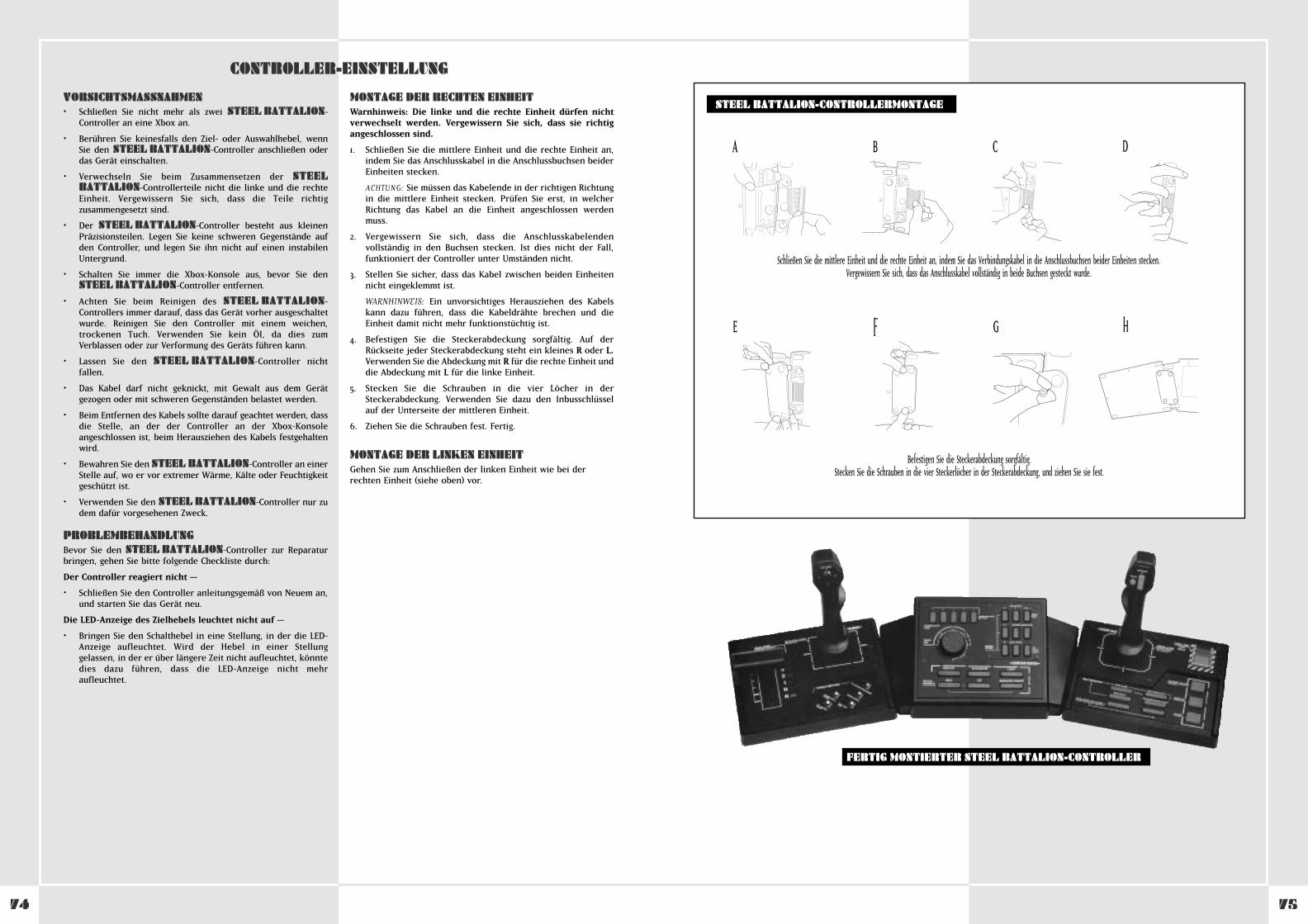
CONTROLLER-EINSTELLUNG
VORSICHTSMASSNAHMEN• Schließen Sie nicht mehr als zwei STEEL BATTALION-
Controller an eine Xbox an.
• Berühren Sie keinesfalls den Ziel- oder Auswahlhebel, wennSie den STEEL BATTALION-Controller anschließen oderdas Gerät einschalten.
• Verwechseln Sie beim Zusammensetzen der STEELBATTALION-Controllerteile nicht die linke und die rechteEinheit. Vergewissern Sie sich, dass die Teile richtigzusammengesetzt sind.
• Der STEEL BATTALION-Controller besteht aus kleinenPräzisionsteilen. Legen Sie keine schweren Gegenstände aufden Controller, und legen Sie ihn nicht auf einen instabilenUntergrund.
• Schalten Sie immer die Xbox-Konsole aus, bevor Sie denSTEEL BATTALION-Controller entfernen.
• Achten Sie beim Reinigen des STEEL BATTALION-Controllers immer darauf, dass das Gerät vorher ausgeschaltetwurde. Reinigen Sie den Controller mit einem weichen,trockenen Tuch. Verwenden Sie kein Öl, da dies zumVerblassen oder zur Verformung des Geräts führen kann.
• Lassen Sie den STEEL BATTALION-Controller nichtfallen.
• Das Kabel darf nicht geknickt, mit Gewalt aus dem Gerätgezogen oder mit schweren Gegenständen belastet werden.
• Beim Entfernen des Kabels sollte darauf geachtet werden, dassdie Stelle, an der der Controller an der Xbox-Konsoleangeschlossen ist, beim Herausziehen des Kabels festgehaltenwird.
• Bewahren Sie den STEEL BATTALION-Controller an einerStelle auf, wo er vor extremer Wärme, Kälte oder Feuchtigkeitgeschützt ist.
• Verwenden Sie den STEEL BATTALION-Controller nur zudem dafür vorgesehenen Zweck.
PROBLEMBEHANDLUNGBevor Sie den STEEL BATTALION-Controller zur Reparaturbringen, gehen Sie bitte folgende Checkliste durch:
Der Controller reagiert nicht –
• Schließen Sie den Controller anleitungsgemäß von Neuem an,und starten Sie das Gerät neu.
Die LED-Anzeige des Zielhebels leuchtet nicht auf –
• Bringen Sie den Schalthebel in eine Stellung, in der die LED-Anzeige aufleuchtet. Wird der Hebel in einer Stellunggelassen, in der er über längere Zeit nicht aufleuchtet, könntedies dazu führen, dass die LED-Anzeige nicht mehraufleuchtet.
MONTAGE DER RECHTEN EINHEITWarnhinweis: Die linke und die rechte Einheit dürfen nichtverwechselt werden. Vergewissern Sie sich, dass sie richtigangeschlossen sind.
1. Schließen Sie die mittlere Einheit und die rechte Einheit an,indem Sie das Anschlusskabel in die Anschlussbuchsen beiderEinheiten stecken.
ACHTUNG: Sie müssen das Kabelende in der richtigen Richtungin die mittlere Einheit stecken. Prüfen Sie erst, in welcherRichtung das Kabel an die Einheit angeschlossen werdenmuss.
2. Vergewissern Sie sich, dass die Anschlusskabelendenvollständig in den Buchsen stecken. Ist dies nicht der Fall,funktioniert der Controller unter Umständen nicht.
3. Stellen Sie sicher, dass das Kabel zwischen beiden Einheitennicht eingeklemmt ist.
WARNHINWEIS: Ein unvorsichtiges Herausziehen des Kabelskann dazu führen, dass die Kabeldrähte brechen und dieEinheit damit nicht mehr funktionstüchtig ist.
4. Befestigen Sie die Steckerabdeckung sorgfältig. Auf derRückseite jeder Steckerabdeckung steht ein kleines R oder L.Verwenden Sie die Abdeckung mit R für die rechte Einheit unddie Abdeckung mit L für die linke Einheit.
5. Stecken Sie die Schrauben in die vier Löcher in derSteckerabdeckung. Verwenden Sie dazu den Inbusschlüsselauf der Unterseite der mittleren Einheit.
6. Ziehen Sie die Schrauben fest. Fertig.
MONTAGE DER LINKEN EINHEITGehen Sie zum Anschließen der linken Einheit wie bei derrechten Einheit (siehe oben) vor.
STEEL BATTALION-CONTROLLERMONTAGE
FERTIG MONTIERTER STEEL BATTALION-CONTROLLER
Schließen Sie die mittlere Einheit und die rechte Einheit an, indem Sie das Verbindungskabel in die Anschlussbuchsen beider Einheiten stecken. Vergewissern Sie sich, dass das Anschlusskabel vollständig in beide Buchsen gesteckt wurde.
Befestigen Sie die Steckerabdeckung sorgfältig.Stecken Sie die Schrauben in die vier Steckerlöcher in der Steckerabdeckung, und ziehen Sie sie fest.
A B C D
E F G H
7574
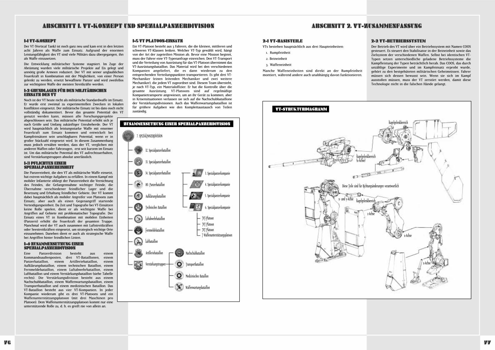
7776
2-1 VT-BASISTEILEVTs bestehen hauptsächlich aus drei Haupteinheiten:
1. Rumpfeinheit
2. Beineinheit
3. Waffeneinheit
Manche Waffeneinheiten sind direkt an der Rumpfeinheitmontiert, während andere auch unabhängig davon funktionieren.
2-2 VT-BETRIEBSSYSTEMDer Betrieb des VT wird über ein Betriebssystem mit Namen COOSgesteuert. Es steuert den Stabilisator in der Beineinheit sowie dasZielsystem der verschiedenen Waffen. Selbst bei identischen VT-Typen setzen unterschiedliche geladene Betriebssysteme dieKampfleistung der Typen beträchtlich herab. Das COOS, das durchunzählige Experimente und im Kampfeinsatz erprobt wurde,gehört zu den bestgehüteten militärischen Geheimnissen. Fahrermüssen sich dessen bewusst sein. Wenn sie sich im Kampfausstoßen müssen, muss der VT zerstört werden, damit dieseTechnologie nicht in die falschen Hände gelangt.
1-1 VT-KONZEPTDer VT (Vertical Tank) ist noch ganz neu und kam erst in den letztenacht Jahren als Waffe zum Einsatz. Aufgrund der enormenLeistungsfähigkeit des VT sind viele Militärs dazu übergegangen, ihnals Waffe einzusetzen.
Die Entwicklung militärischer Systeme stagniert. Im Zuge derAbrüstung wurden viele militärische Projekte auf Eis gelegt undunnötig große Armeen reduziert. Der VT mit seiner unglaublichenFeuerkraft in Kombination mit der Möglichkeit, von einer Persongelenkt zu werden, ersetzt bewaffnete Panzer und wird zweifelloszur wichtigsten Waffe der meisten Streitkräfte werden.
1-2 GRUNDLAGEN FÜR DEN MILITÄRISCHENEINSATZ DES VTNoch ist der VT heute nicht als militärische Standardwaffe im Einsatz.Er wurde erst zweimal zu experimentellen Zwecken in lokalenKonflikten eingesetzt. Der militärische Einsatz ist bis dato noch nichtvollständig dokumentiert. Bevor das gesamte Potential des VTgenutzt werden kann, müssen alle Forschungsprojekteabgeschlossen sein. Das militärische Potential erhöht sich jenach Größe und Umfang zukünftiger Unruheherde. Der VTwird hauptsächlich als leistungsstarke Waffe mit enormerFeuerkraft zum Einsatz kommen und entwickelt beiKampfeinsätzen sein unschlagbares Potential, wenn er ingroßer Stückzahl eingesetzt wird. In diesem Zusammenhangmuss jedoch erwähnt werden, dass der VT, verglichen mitanderen Waffen oder Fahrzeugen, erst seit kurzem im Einsatzist. Um das militärische Potential des VT aufrechtzuerhalten,sind Verstärkungstruppen absolut unerlässlich.
1-3 PFLICHTEN EINERSPEZIALPANZEREINHEITDie Panzereinheit, die den VT als militärische Waffe einsetzt,hat extrem wichtige Aufgaben zu erfüllen. In einem Kampf mitmobiler Infanterie obliegt der Panzereinheit die Vernichtungdes Feindes, die Gefangennahme wichtiger Feinde, dieÜbernahme verschiedener feindlicher Lager und dieBesetzung und Erhaltung feindlicher Gebiete. Der VT kommtdabei hauptsächlich als mobiler Angreifer von Platoons zumEinsatz, aber auch als einen Gegenangriff startendeVerteidigungseinheit. Da Zeit und Topografie bei VT-Einsätzenkeine Rolle spielen, dient er als wichtigste Waffe beiAngriffen auf Gebiete mit problematischer Topografie. DerEinsatz eines VT in Kombination mit mobilen Einheiten(Panzern) erhöht die Feuerkraft der gesamten Truppe.Manchmal wird der VT auch zusammen mit Luftstreitkräftenoder Seestreitkräften eingesetzt, um strategisch wichtige Orteeinzunehmen. Daneben dient er auch als strategische Waffebei Angriffen hinter feindlichen Linien.
1-4 ZUSAMMENSETZUNG EINERSPEZIALPANZERDIVISIONEine Panzerdivision besteht aus einemKommandoaußenposten, drei VT-Bataillonen, einemPanzerbataillon, einem Artilleriebataillon, einemAufklärungsbataillon, einem technischen Bataillon, einemFernmeldebataillon, einem Luftabwehrbataillon, einemLuftbataillon und einem Verstärkungsbataillon (siehe Tabellerechts). Die Verstärkungsdivision besteht aus einemNachschubbataillon, einem Waffenwartungsbataillon, einemTransportbataillon und einem medizinischen Bataillon. DasVT-Bataillon besteht aus vier VT-Kompanien. In jederKompanie wiederum gibt es drei VT-Platoons und einWaffenunterstützungsplatoon (mit drei Maschinen proPlatoon). Dem Waffenunterstützungsplatoon kommt nur eineunterstützende Rolle zu, d. h. es greift nie von allein an.
1-5 VT PLATOON-EINSATZEin VT-Platoon besteht aus 3 Fahrern, die die kleinen, mittleren undschweren VT-Klassen lenken. Welcher VT-Typ gewählt wird, hängtvon der Art der zugeteilten Mission ab. Bevor eine Mission beginnt,muss der Fahrer eine VT-Typenanfrage einreichen. Den VT-Transportund die Verteilung von Ausrüstung für das VT-Platoon übernimmt dasVT-Ausrüstungsbataillon. Das Material wird bei den verschiedenenKompanien angeliefert, die es dann wiederum zu denentsprechenden Verteilungspunkten transportieren. Es gibt drei VT-Mechaniker (einen leitenden Mechaniker und zwei weitereMechaniker), die jedem VT zugeordnet sind. Diesem Team übersteht,je nach VT-Typ, ein Materialoffizier. Er hat die Kontrolle über diegesamte Ausrüstung. VT-Platoons sind auf regelmäßigeKompanietransporte angewiesen, um an ihr Gerät zu kommen, aberin Krisensituationen verlassen sie sich auf die Nachschubbatailloneder Verstärkungsdivisionen. Auch das Waffenwartungsbataillon istfür größere Aufgaben wie den Komplettaustausch von Teilenzuständig.
ABSCHNITT 1. VT-KONZEPT UND SPEZIALPANZERDIVISION ABSCHNITT 2. VT-ZUSAMMENFASSUNG
7. SPEZIALPANZERDIVISION
32. Spezialpanzerbataillon
33. Spezialpanzerbataillon
34. Spezialpanzerbataillon 3. Spezialpanzerkompanie
4. Spezialpanzerkompanie
5. Spezialpanzerkompanie
6. Spezialpanzerkompanie
‡VT-Platoon‡VT Platoon‡VT Platoon‡ Waffenunterstützungsplatoon
Nachschubbataillon
Transportbataillon
Medizinisches Bataillon
Waffenwartungsbataillon
80. Panzerbataillon
Aufklärungsbataillon
Technisches Bataillon
Luftabwehrbataillon
Fernmeldebataillon
Luftbataillon
Artilleriebataillon
Verstärkungstruppen
ZUSAMMENSETZUNG EINER SPEZIALPANZERDIVISION
VT-STRUKTURDIAGRAMM
Kugelgelenkbereich(x-Achse)
x- und y-Achse
z-Achse
x-Achse
x-Achse
Diese Teile sind für Richtungsänderungen verantwortlich
Kugelgelenkbereich
Kugelgelenkbereich
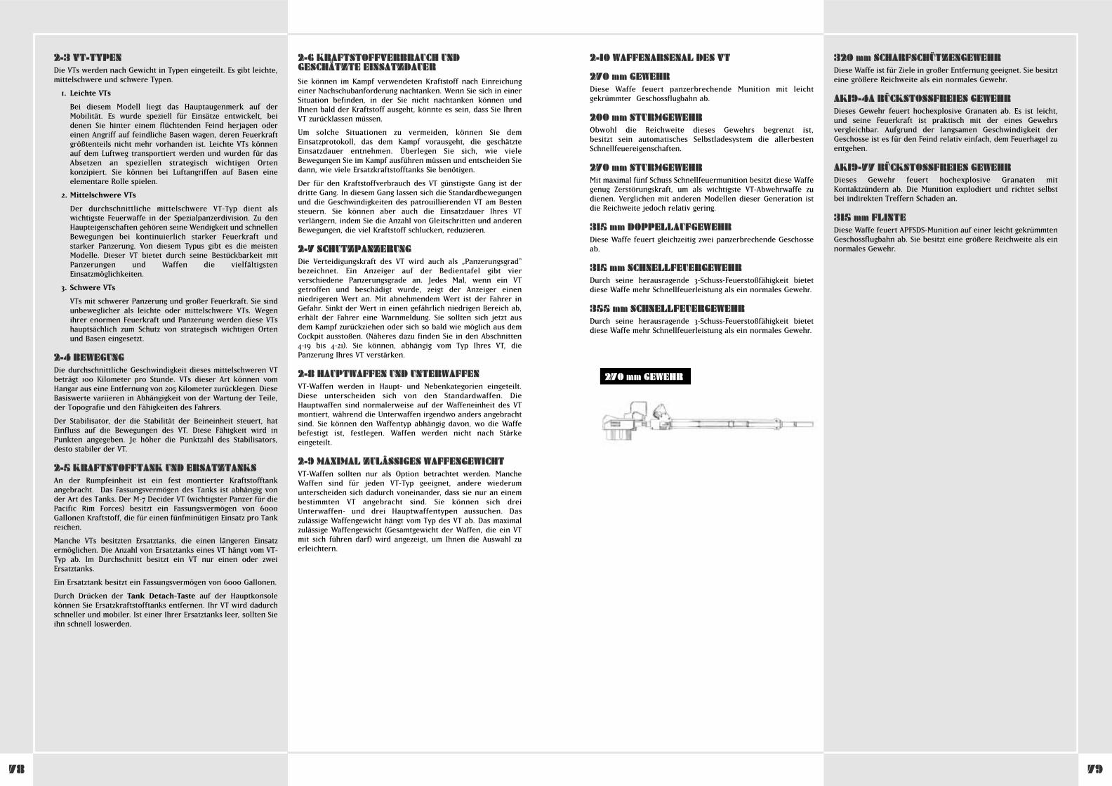
7978
2-10 WAFFENARSENAL DES VT
270 mm GEWEHRDiese Waffe feuert panzerbrechende Munition mit leichtgekrümmter Geschossflugbahn ab.
200 mm STURMGEWEHRObwohl die Reichweite dieses Gewehrs begrenzt ist, besitzt sein automatisches Selbstladesystem die allerbestenSchnellfeuereigenschaften.
270 mm STURMGEWEHRMit maximal fünf Schuss Schnellfeuermunition besitzt diese Waffegenug Zerstörungskraft, um als wichtigste VT-Abwehrwaffe zudienen. Verglichen mit anderen Modellen dieser Generation istdie Reichweite jedoch relativ gering.
315 mm DOPPELLAUFGEWEHRDiese Waffe feuert gleichzeitig zwei panzerbrechende Geschosseab.
315 mm SCHNELLFEUERGEWEHRDurch seine herausragende 3-Schuss-Feuerstoßfähigkeit bietetdiese Waffe mehr Schnellfeuerleistung als ein normales Gewehr.
355 mm SCHNELLFEUERGEWEHRDurch seine herausragende 3-Schuss-Feuerstoßfähigkeit bietetdiese Waffe mehr Schnellfeuerleistung als ein normales Gewehr.
320 mm SCHARFSCHÜTZENGEWEHRDiese Waffe ist für Ziele in großer Entfernung geeignet. Sie besitzteine größere Reichweite als ein normales Gewehr.
AK19-4A RÜCKSTOSSFREIES GEWEHRDieses Gewehr feuert hochexplosive Granaten ab. Es ist leicht,und seine Feuerkraft ist praktisch mit der eines Gewehrsvergleichbar. Aufgrund der langsamen Geschwindigkeit derGeschosse ist es für den Feind relativ einfach, dem Feuerhagel zuentgehen.
AK19-77 RÜCKSTOSSFREIES GEWEHRDieses Gewehr feuert hochexplosive Granaten mitKontaktzündern ab. Die Munition explodiert und richtet selbstbei indirekten Treffern Schaden an.
315 mm FLINTEDiese Waffe feuert APFSDS-Munition auf einer leicht gekrümmtenGeschossflugbahn ab. Sie besitzt eine größere Reichweite als einnormales Gewehr.
2-3 VT-TYPENDie VTs werden nach Gewicht in Typen eingeteilt. Es gibt leichte,mittelschwere und schwere Typen.
1. Leichte VTs
Bei diesem Modell liegt das Hauptaugenmerk auf derMobilität. Es wurde speziell für Einsätze entwickelt, beidenen Sie hinter einem flüchtenden Feind herjagen odereinen Angriff auf feindliche Basen wagen, deren Feuerkraftgrößtenteils nicht mehr vorhanden ist. Leichte VTs könnenauf dem Luftweg transportiert werden und wurden für dasAbsetzen an speziellen strategisch wichtigen Ortenkonzipiert. Sie können bei Luftangriffen auf Basen eineelementare Rolle spielen.
2. Mittelschwere VTs
Der durchschnittliche mittelschwere VT-Typ dient alswichtigste Feuerwaffe in der Spezialpanzerdivision. Zu denHaupteigenschaften gehören seine Wendigkeit und schnellenBewegungen bei kontinuierlich starker Feuerkraft undstarker Panzerung. Von diesem Typus gibt es die meistenModelle. Dieser VT bietet durch seine Bestückbarkeit mitPanzerungen und Waffen die vielfältigstenEinsatzmöglichkeiten.
3. Schwere VTs
VTs mit schwerer Panzerung und großer Feuerkraft. Sie sindunbeweglicher als leichte oder mittelschwere VTs. Wegenihrer enormen Feuerkraft und Panzerung werden diese VTshauptsächlich zum Schutz von strategisch wichtigen Ortenund Basen eingesetzt.
2-4 BEWEGUNGDie durchschnittliche Geschwindigkeit dieses mittelschweren VTbeträgt 100 Kilometer pro Stunde. VTs dieser Art können vomHangar aus eine Entfernung von 205 Kilometer zurücklegen. DieseBasiswerte variieren in Abhängigkeit von der Wartung der Teile,der Topografie und den Fähigkeiten des Fahrers.
Der Stabilisator, der die Stabilität der Beineinheit steuert, hatEinfluss auf die Bewegungen des VT. Diese Fähigkeit wird inPunkten angegeben. Je höher die Punktzahl des Stabilisators,desto stabiler der VT.
2-5 KRAFTSTOFFTANK UND ERSATZTANKSAn der Rumpfeinheit ist ein fest montierter Kraftstofftankangebracht. Das Fassungsvermögen des Tanks ist abhängig vonder Art des Tanks. Der M-7 Decider VT (wichtigster Panzer für diePacific Rim Forces) besitzt ein Fassungsvermögen von 6000Gallonen Kraftstoff, die für einen fünfminütigen Einsatz pro Tankreichen.
Manche VTs besitzten Ersatztanks, die einen längeren Einsatzermöglichen. Die Anzahl von Ersatztanks eines VT hängt vom VT-Typ ab. Im Durchschnitt besitzt ein VT nur einen oder zweiErsatztanks.
Ein Ersatztank besitzt ein Fassungsvermögen von 6000 Gallonen.
Durch Drücken der Tank Detach-Taste auf der Hauptkonsolekönnen Sie Ersatzkraftstofftanks entfernen. Ihr VT wird dadurchschneller und mobiler. Ist einer Ihrer Ersatztanks leer, sollten Sieihn schnell loswerden.
2-6 KRAFTSTOFFVERBRAUCH UNDGESCHÄTZTE EINSATZDAUERSie können im Kampf verwendeten Kraftstoff nach Einreichungeiner Nachschubanforderung nachtanken. Wenn Sie sich in einerSituation befinden, in der Sie nicht nachtanken können undIhnen bald der Kraftstoff ausgeht, könnte es sein, dass Sie IhrenVT zurücklassen müssen.
Um solche Situationen zu vermeiden, können Sie demEinsatzprotokoll, das dem Kampf vorausgeht, die geschätzteEinsatzdauer entnehmen. Überlegen Sie sich, wie vieleBewegungen Sie im Kampf ausführen müssen und entscheiden Siedann, wie viele Ersatzkraftstofftanks Sie benötigen.
Der für den Kraftstoffverbrauch des VT günstigste Gang ist derdritte Gang. In diesem Gang lassen sich die Standardbewegungenund die Geschwindigkeiten des patrouillierenden VT am Bestensteuern. Sie können aber auch die Einsatzdauer Ihres VTverlängern, indem Sie die Anzahl von Gleitschritten und anderenBewegungen, die viel Kraftstoff schlucken, reduzieren.
2-7 SCHUTZPANZERUNGDie Verteidigungskraft des VT wird auch als „Panzerungsgrad“bezeichnet. Ein Anzeiger auf der Bedientafel gibt vierverschiedene Panzerungsgrade an. Jedes Mal, wenn ein VTgetroffen und beschädigt wurde, zeigt der Anzeiger einenniedrigeren Wert an. Mit abnehmendem Wert ist der Fahrer inGefahr. Sinkt der Wert in einen gefährlich niedrigen Bereich ab,erhält der Fahrer eine Warnmeldung. Sie sollten sich jetzt ausdem Kampf zurückziehen oder sich so bald wie möglich aus demCockpit ausstoßen. (Näheres dazu finden Sie in den Abschnitten4-19 bis 4-21). Sie können, abhängig vom Typ Ihres VT, diePanzerung Ihres VT verstärken.
2-8 HAUPTWAFFEN UND UNTERWAFFENVT-Waffen werden in Haupt- und Nebenkategorien eingeteilt.Diese unterscheiden sich von den Standardwaffen. DieHauptwaffen sind normalerweise auf der Waffeneinheit des VTmontiert, während die Unterwaffen irgendwo anders angebrachtsind. Sie können den Waffentyp abhängig davon, wo die Waffebefestigt ist, festlegen. Waffen werden nicht nach Stärkeeingeteilt.
2-9 MAXIMAL ZULÄSSIGES WAFFENGEWICHTVT-Waffen sollten nur als Option betrachtet werden. MancheWaffen sind für jeden VT-Typ geeignet, andere wiederumunterscheiden sich dadurch voneinander, dass sie nur an einembestimmten VT angebracht sind. Sie können sich dreiUnterwaffen- und drei Hauptwaffentypen aussuchen. Daszulässige Waffengewicht hängt vom Typ des VT ab. Das maximalzulässige Waffengewicht (Gesamtgewicht der Waffen, die ein VTmit sich führen darf) wird angezeigt, um Ihnen die Auswahl zuerleichtern.
270 mm GEWEHR
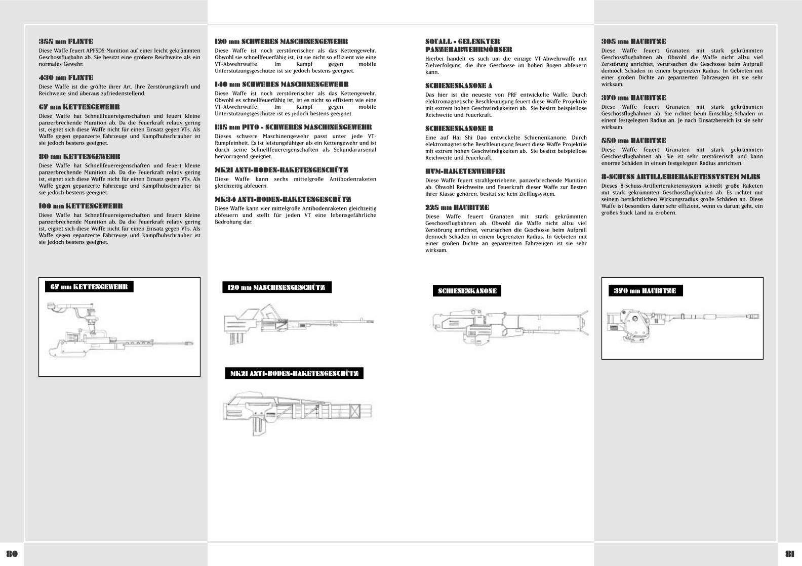
8180
SQUALL – GELENKTERPANZERABWEHRMÖRSERHierbei handelt es such um die einzige VT-Abwehrwaffe mitZielverfolgung, die ihre Geschosse im hohen Bogen abfeuernkann.
SCHIENENKANONE ADas hier ist die neueste von PRF entwickelte Waffe. Durchelektromagnetische Beschleunigung feuert diese Waffe Projektilemit extrem hohen Geschwindigkeiten ab. Sie besitzt beispielloseReichweite und Feuerkraft.
SCHIENENKANONE BEine auf Hai Shi Dao entwickelte Schienenkanone. Durchelektromagnetische Beschleunigung feuert diese Waffe Projektilemit extrem hohen Geschwindigkeiten ab. Sie besitzt beispielloseReichweite und Feuerkraft.
HVM-RAKETENWERFERDiese Waffe feuert strahlgetriebene, panzerbrechende Munitionab. Obwohl Reichweite und Feuerkraft dieser Waffe zur Bestenihrer Klasse gehören, besitzt sie kein Zielflugsystem.
225 mm HAUBITZEDiese Waffe feuert Granaten mit stark gekrümmtenGeschossflugbahnen ab. Obwohl die Waffe nicht allzu vielZerstörung anrichtet, verursachen die Geschosse beim Aufpralldennoch Schäden in einem begrenzten Radius. In Gebieten miteiner großen Dichte an gepanzerten Fahrzeugen ist sie sehrwirksam.
305 mm HAUBITZEDiese Waffe feuert Granaten mit stark gekrümmtenGeschossflugbahnen ab. Obwohl die Waffe nicht allzu vielZerstörung anrichtet, verursachen die Geschosse beim Aufpralldennoch Schäden in einem begrenzten Radius. In Gebieten miteiner großen Dichte an gepanzerten Fahrzeugen ist sie sehrwirksam.
370 mm HAUBITZEDiese Waffe feuert Granaten mit stark gekrümmtenGeschossflugbahnen ab. Sie richtet beim Einschlag Schäden ineinem festgelegten Radius an. Je nach Einsatzbereich ist sie sehrwirksam.
550 mm HAUBITZEDiese Waffe feuert Granaten mit stark gekrümmtenGeschossflugbahnen ab. Sie ist sehr zerstörerisch und kannenorme Schäden in einem festgelegten Radius anrichten.
8-SCHUSS ARTILLERIERAKETENSYSTEM MLRSDieses 8-Schuss-Artillerieraketensystem schießt große Raketenmit stark gekrümmten Geschossflugbahnen ab. Es richtet mitseinem beträchtlichen Wirkungsradius große Schäden an. DieseWaffe ist besonders dann sehr effizient, wenn es darum geht, eingroßes Stück Land zu erobern.
355 mm FLINTEDiese Waffe feuert APFSDS-Munition auf einer leicht gekrümmtenGeschossflugbahn ab. Sie besitzt eine größere Reichweite als einnormales Gewehr.
430 mm FLINTEDiese Waffe ist die größte ihrer Art. Ihre Zerstörungskraft undReichweite sind überaus zufriedenstellend.
67 mm KETTENGEWEHRDiese Waffe hat Schnellfeuereigenschaften und feuert kleinepanzerbrechende Munition ab. Da die Feuerkraft relativ geringist, eignet sich diese Waffe nicht für einen Einsatz gegen VTs. AlsWaffe gegen gepanzerte Fahrzeuge und Kampfhubschrauber istsie jedoch bestens geeignet.
80 mm KETTENGEWEHRDiese Waffe hat Schnellfeuereigenschaften und feuert kleinepanzerbrechende Munition ab. Da die Feuerkraft relativ geringist, eignet sich diese Waffe nicht für einen Einsatz gegen VTs. AlsWaffe gegen gepanzerte Fahrzeuge und Kampfhubschrauber istsie jedoch bestens geeignet.
100 mm KETTENGEWEHRDiese Waffe hat Schnellfeuereigenschaften und feuert kleinepanzerbrechende Munition ab. Da die Feuerkraft relativ geringist, eignet sich diese Waffe nicht für einen Einsatz gegen VTs. AlsWaffe gegen gepanzerte Fahrzeuge und Kampfhubschrauber istsie jedoch bestens geeignet.
120 mm SCHWERES MASCHINENGEWEHRDiese Waffe ist noch zerstörerischer als das Kettengewehr.Obwohl sie schnellfeuerfähig ist, ist sie nicht so effizient wie eineVT-Abwehrwaffe. Im Kampf gegen mobileUnterstützungsgeschütze ist sie jedoch bestens geeignet.
140 mm SCHWERES MASCHINENGEWEHRDiese Waffe ist noch zerstörerischer als das Kettengewehr.Obwohl es schnellfeuerfähig ist, ist es nicht so effizient wie eineVT-Abwehrwaffe. Im Kampf gegen mobileUnterstützungsgeschütze ist es jedoch bestens geeignet.
135 mm PITO - SCHWERES MASCHINENGEWEHRDieses schwere Maschinengewehr passt unter jede VT-Rumpfeinheit. Es ist leistungsfähiger als ein Kettengewehr und istdurch seine Schnellfeuereigenschaften als Sekundärarsenalhervorragend geeignet.
MK21 ANTI-BODEN-RAKETENGESCHÜTZDiese Waffe kann sechs mittelgroße Antibodenraketengleichzeitig abfeuern.
MK34 ANTI-BODEN-RAKETENGESCHÜTZDiese Waffe kann vier mittelgroße Antibodenraketen gleichzeitigabfeuern und stellt für jeden VT eine lebensgefährlicheBedrohung dar.
SCHIENENKANONE 370 mm HAUBITZE67 mm KETTENGEWEHR 120 mm MASCHINENGESCHÜTZ
MK21 ANTI-BODEN-RAKETENGESCHÜTZ
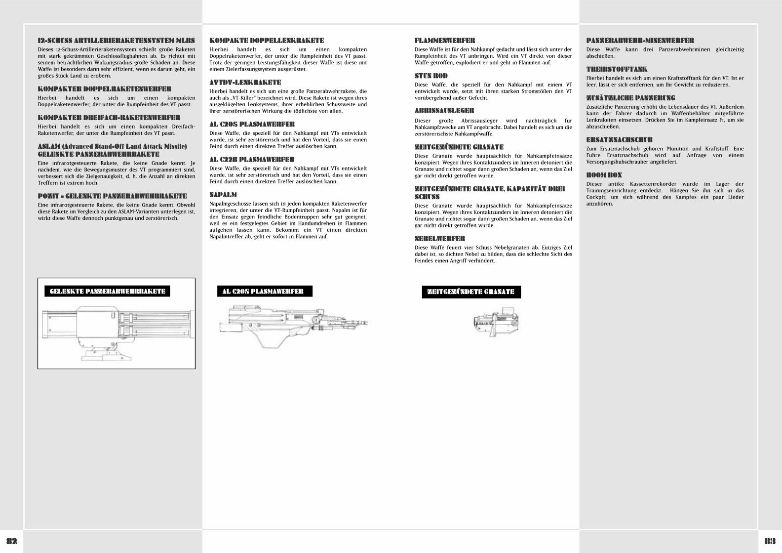
8382
FLAMMENWERFERDiese Waffe ist für den Nahkampf gedacht und lässt sich unter derRumpfeinheit des VT anbringen. Wird ein VT direkt von dieserWaffe getroffen, explodiert er und geht in Flammen auf.
STUN RODDiese Waffe, die speziell für den Nahkampf mit einem VTentwickelt wurde, setzt mit ihren starken Stromstößen den VTvorübergehend außer Gefecht.
ABRISSAUSLEGERDieser große Abrissausleger wird nachträglich fürNahkampfzwecke am VT angebracht. Dabei handelt es sich um diezerstörerischste Nahkampfwaffe.
ZEITGEZÜNDETE GRANATEDiese Granate wurde hauptsächlich für Nahkampfeinsätzekonzipiert. Wegen ihres Kontaktzünders im Inneren detoniert dieGranate und richtet sogar dann großen Schaden an, wenn das Zielgar nicht direkt getroffen wurde.
ZEITGEZÜNDETE GRANATE, KAPAZITÄT DREISCHUSSDiese Granate wurde hauptsächlich für Nahkampfeinsätzekonzipiert. Wegen ihres Kontaktzünders im Inneren detoniert dieGranate und richtet sogar dann großen Schaden an, wenn das Zielgar nicht direkt getroffen wurde.
NEBELWERFERDiese Waffe feuert vier Schuss Nebelgranaten ab. Einziges Zieldabei ist, so dichten Nebel zu bilden, dass die schlechte Sicht desFeindes einen Angriff verhindert.
PANZERABWEHR-MINENWERFERDiese Waffe kann drei Panzerabwehrminen gleichzeitigabschießen.
TREIBSTOFFTANKHierbei handelt es sich um einen Kraftstofftank für den VT. Ist erleer, lässt er sich entfernen, um Ihr Gewicht zu reduzieren.
ZUSÄTZLICHE PANZERUNGZusätzliche Panzerung erhöht die Lebensdauer des VT. Außerdemkann der Fahrer dadurch im Waffenbehälter mitgeführteLenkraketen einsetzen. Drücken Sie im Kampfeinsatz F1, um sieabzuschießen.
ERSATZNACHSCHUBZum Ersatznachschub gehören Munition und Kraftstoff. Eine Fuhre Ersatznachschub wird auf Anfrage von einemVersorgungshubschrauber angeliefert.
BOOM BOXDieser antike Kassettenrekorder wurde im Lager derTrainingseinrichtung entdeckt. Hängen Sie ihn sich in dasCockpit, um sich während des Kampfes ein paar Liederanzuhören.
12-SCHUSS ARTILLERIERAKETENSYSTEM MLRSDieses 12-Schuss-Artillerieraketensystem schießt große Raketenmit stark gekrümmten Geschlossflugbahnen ab. Es richtet mitseinem beträchtlichen Wirkungsradius große Schäden an. DieseWaffe ist besonders dann sehr effizient, wenn es darum geht, eingroßes Stück Land zu erobern.
KOMPAKTER DOPPELRAKETENWERFERHierbei handelt es sich um einen kompaktenDoppelraketenwerfer, der unter die Rumpfeinheit des VT passt.
KOMPAKTER DREIFACH-RAKETENWERFERHierbei handelt es sich um einen kompakten Dreifach-Raketenwerfer, der unter die Rumpfeinheit des VT passt.
ASLAM (Advanced Stand-Off Land Attack Missile)GELENKTE PANZERABWEHRRAKETEEine infrarotgesteuerte Rakete, die keine Gnade kennt. Jenachdem, wie die Bewegungsmuster des VT programmiert sind,verbessert sich die Zielgenauigkeit, d. h. die Anzahl an direktenTreffern ist extrem hoch.
POZIT – GELENKTE PANZERABWEHRRAKETEEine infrarotgesteuerte Rakete, die keine Gnade kennt. Obwohldiese Rakete im Vergleich zu den ASLAM-Varianten unterlegen ist,wirkt diese Waffe dennoch punktgenau und zerstörerisch.
KOMPAKTE DOPPELLENKRAKETEHierbei handelt es sich um einen kompaktenDoppelraketenwerfer, der unter die Rumpfeinheit des VT passt.Trotz der geringen Leistungsfähigkeit dieser Waffe ist diese miteinem Zielerfassungssystem ausgerüstet.
AVTDV-LENKRAKETEHierbei handelt es sich um eine große Panzerabwehrrakete, dieauch als „VT-Killer“ bezeichnet wird. Diese Rakete ist wegen ihresausgeklügelten Lenksystems, ihrer erheblichen Schussweite undihrer zerstörerischen Wirkung die tödlichste von allen.
AL C205 PLASMAWERFERDiese Waffe, die speziell für den Nahkampf mit VTs entwickeltwurde, ist sehr zerstörerisch und hat den Vorteil, dass sie einenFeind durch einen direkten Treffer auslöschen kann.
AL C22B PLASMAWERFERDiese Waffe, die speziell für den Nahkampf mit VTs entwickeltwurde, ist sehr zerstörerisch und hat den Vorteil, dass sie einenFeind durch einen direkten Treffer auslöschen kann.
NAPALMNapalmgeschosse lassen sich in jeden kompakten Raketenwerferintegrieren, der unter die VT-Rumpfeinheit passt. Napalm ist fürden Einsatz gegen feindliche Bodentruppen sehr gut geeignet,weil es ein festgelegtes Gebiet im Handumdrehen in Flammenaufgehen lassen kann. Bekommt ein VT einen direktenNapalmtreffer ab, geht er sofort in Flammen auf.
AL C205 PLASMAWERFERGELENKTE PANZERABWEHRRAKETE ZEITGEZÜNDETE GRANATE
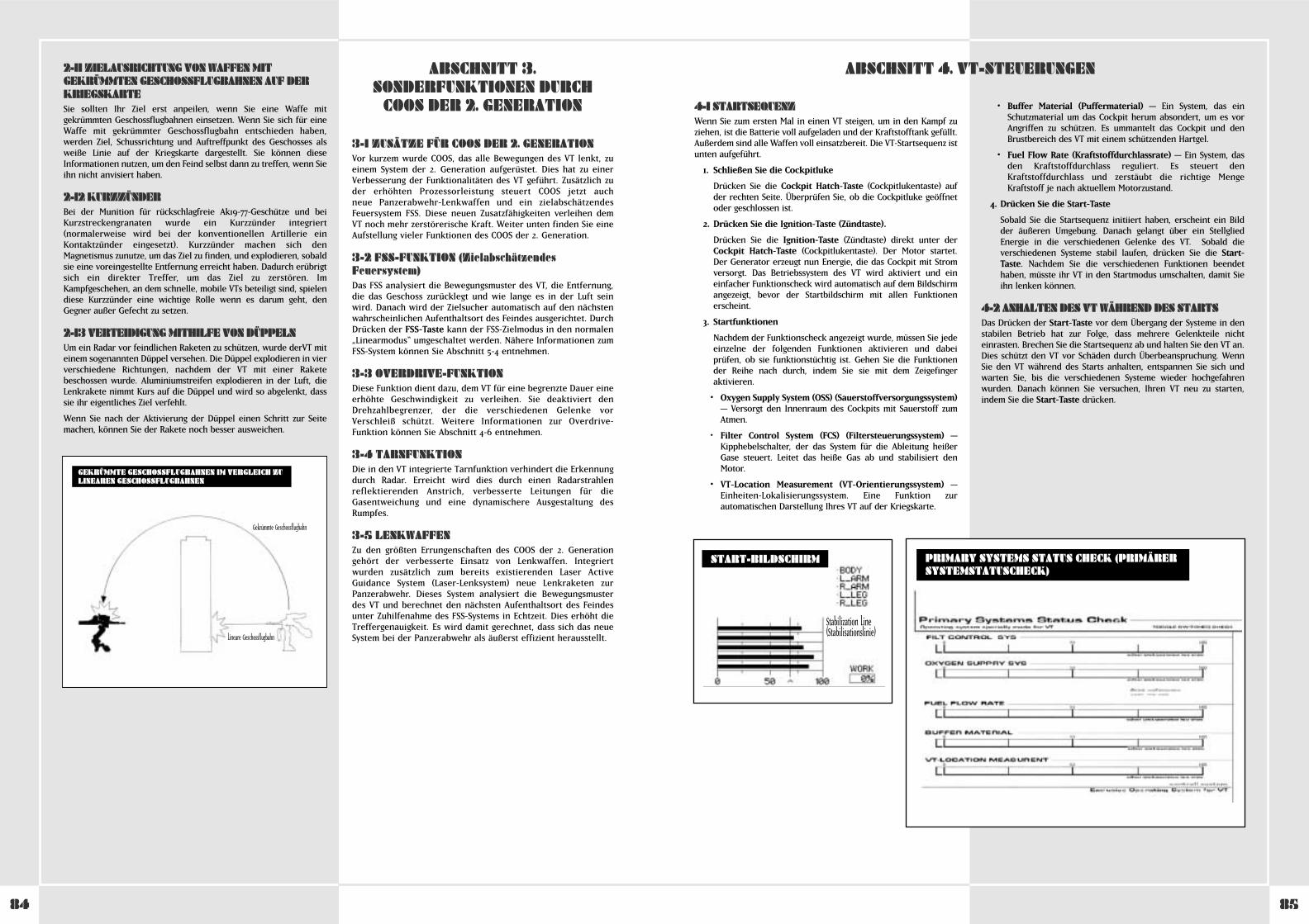
8584
2-11 ZIELAUSRICHTUNG VON WAFFEN MITGEKRÜMMTEN GESCHOSSFLUGBAHNEN AUF DERKRIEGSKARTESie sollten Ihr Ziel erst anpeilen, wenn Sie eine Waffe mitgekrümmten Geschossflugbahnen einsetzen. Wenn Sie sich für eineWaffe mit gekrümmter Geschossflugbahn entschieden haben,werden Ziel, Schussrichtung und Auftreffpunkt des Geschosses alsweiße Linie auf der Kriegskarte dargestellt. Sie können dieseInformationen nutzen, um den Feind selbst dann zu treffen, wenn Sieihn nicht anvisiert haben.
2-12 KURZZÜNDERBei der Munition für rückschlagfreie Ak19-77-Geschütze und beiKurzstreckengranaten wurde ein Kurzzünder integriert(normalerweise wird bei der konventionellen Artillerie einKontaktzünder eingesetzt). Kurzzünder machen sich denMagnetismus zunutze, um das Ziel zu finden, und explodieren, sobaldsie eine voreingestellte Entfernung erreicht haben. Dadurch erübrigtsich ein direkter Treffer, um das Ziel zu zerstören. ImKampfgeschehen, an dem schnelle, mobile VTs beteiligt sind, spielendiese Kurzzünder eine wichtige Rolle wenn es darum geht, denGegner außer Gefecht zu setzen.
2-13 VERTEIDIGUNG MITHILFE VON DÜPPELNUm ein Radar vor feindlichen Raketen zu schützen, wurde derVT miteinem sogenannten Düppel versehen. Die Düppel explodieren in vierverschiedene Richtungen, nachdem der VT mit einer Raketebeschossen wurde. Aluminiumstreifen explodieren in der Luft, dieLenkrakete nimmt Kurs auf die Düppel und wird so abgelenkt, dasssie ihr eigentliches Ziel verfehlt.
Wenn Sie nach der Aktivierung der Düppel einen Schritt zur Seitemachen, können Sie der Rakete noch besser ausweichen.
GEKRÜMMTE GESCHOSSFLUGBAHNEN IM VERGLEICH ZULINEAREN GESCHOSSFLUGBAHNEN
Gekrümmte Geschossflugbahn
Lineare Geschossflugbahn
3-1 ZUSÄTZE FÜR COOS DER 2. GENERATIONVor kurzem wurde COOS, das alle Bewegungen des VT lenkt, zueinem System der 2. Generation aufgerüstet. Dies hat zu einerVerbesserung der Funktionalitäten des VT geführt. Zusätzlich zuder erhöhten Prozessorleistung steuert COOS jetzt auch neue Panzerabwehr-Lenkwaffen und ein zielabschätzendesFeuersystem FSS. Diese neuen Zusatzfähigkeiten verleihen demVT noch mehr zerstörerische Kraft. Weiter unten finden Sie eineAufstellung vieler Funktionen des COOS der 2. Generation.
3-2 FSS-FUNKTION (ZielabschätzendesFeuersystem)Das FSS analysiert die Bewegungsmuster des VT, die Entfernung,die das Geschoss zurücklegt und wie lange es in der Luft seinwird. Danach wird der Zielsucher automatisch auf den nächstenwahrscheinlichen Aufenthaltsort des Feindes ausgerichtet. DurchDrücken der FSS-Taste kann der FSS-Zielmodus in den normalen„Linearmodus“ umgeschaltet werden. Nähere Informationen zumFSS-System können Sie Abschnitt 5-4 entnehmen.
3-3 OVERDRIVE-FUNKTIONDiese Funktion dient dazu, dem VT für eine begrenzte Dauer eineerhöhte Geschwindigkeit zu verleihen. Sie deaktiviert denDrehzahlbegrenzer, der die verschiedenen Gelenke vorVerschleiß schützt. Weitere Informationen zur Overdrive-Funktion können Sie Abschnitt 4-6 entnehmen.
3-4 TARNFUNKTIONDie in den VT integrierte Tarnfunktion verhindert die Erkennungdurch Radar. Erreicht wird dies durch einen Radarstrahlenreflektierenden Anstrich, verbesserte Leitungen für dieGasentweichung und eine dynamischere Ausgestaltung desRumpfes.
3-5 LENKWAFFENZu den größten Errungenschaften des COOS der 2. Generationgehört der verbesserte Einsatz von Lenkwaffen. Integriertwurden zusätzlich zum bereits existierenden Laser ActiveGuidance System (Laser-Lenksystem) neue Lenkraketen zurPanzerabwehr. Dieses System analysiert die Bewegungsmusterdes VT und berechnet den nächsten Aufenthaltsort des Feindesunter Zuhilfenahme des FSS-Systems in Echtzeit. Dies erhöht dieTreffergenauigkeit. Es wird damit gerechnet, dass sich das neueSystem bei der Panzerabwehr als äußerst effizient herausstellt.
ABSCHNITT 3.SONDERFUNKTIONEN DURCH
COOS DER 2. GENERATION 4-1 STARTSEQUENZWenn Sie zum ersten Mal in einen VT steigen, um in den Kampf zuziehen, ist die Batterie voll aufgeladen und der Kraftstofftank gefüllt.Außerdem sind alle Waffen voll einsatzbereit. Die VT-Startsequenz istunten aufgeführt.
1. Schließen Sie die Cockpitluke
Drücken Sie die Cockpit Hatch-Taste (Cockpitlukentaste) aufder rechten Seite. Überprüfen Sie, ob die Cockpitluke geöffnetoder geschlossen ist.
2. Drücken Sie die Ignition-Taste (Zündtaste).
Drücken Sie die Ignition-Taste (Zündtaste) direkt unter derCockpit Hatch-Taste (Cockpitlukentaste). Der Motor startet.Der Generator erzeugt nun Energie, die das Cockpit mit Stromversorgt. Das Betriebssystem des VT wird aktiviert und eineinfacher Funktionscheck wird automatisch auf dem Bildschirmangezeigt, bevor der Startbildschirm mit allen Funktionenerscheint.
3. Startfunktionen
Nachdem der Funktionscheck angezeigt wurde, müssen Sie jedeeinzelne der folgenden Funktionen aktivieren und dabeiprüfen, ob sie funktionstüchtig ist. Gehen Sie die Funktionender Reihe nach durch, indem Sie sie mit dem Zeigefingeraktivieren.
• Oxygen Supply System (OSS) (Sauerstoffversorgungssystem)– Versorgt den Innenraum des Cockpits mit Sauerstoff zumAtmen.
• Filter Control System (FCS) (Filtersteuerungssystem) –Kipphebelschalter, der das System für die Ableitung heißerGase steuert. Leitet das heiße Gas ab und stabilisiert denMotor.
• VT-Location Measurement (VT-Orientierungssystem) –Einheiten-Lokalisierungssystem. Eine Funktion zurautomatischen Darstellung Ihres VT auf der Kriegskarte.
• Buffer Material (Puffermaterial) – Ein System, das einSchutzmaterial um das Cockpit herum absondert, um es vorAngriffen zu schützen. Es ummantelt das Cockpit und denBrustbereich des VT mit einem schützenden Hartgel.
• Fuel Flow Rate (Kraftstoffdurchlassrate) – Ein System, dasden Kraftstoffdurchlass reguliert. Es steuert denKraftstoffdurchlass und zerstäubt die richtige MengeKraftstoff je nach aktuellem Motorzustand.
4. Drücken Sie die Start-Taste
Sobald Sie die Startsequenz initiiert haben, erscheint ein Bildder äußeren Umgebung. Danach gelangt über ein StellgliedEnergie in die verschiedenen Gelenke des VT. Sobald dieverschiedenen Systeme stabil laufen, drücken Sie die Start-Taste. Nachdem Sie die verschiedenen Funktionen beendethaben, müsste ihr VT in den Startmodus umschalten, damit Sieihn lenken können.
4-2 ANHALTEN DES VT WÄHREND DES STARTSDas Drücken der Start-Taste vor dem Übergang der Systeme in denstabilen Betrieb hat zur Folge, dass mehrere Gelenkteile nichteinrasten. Brechen Sie die Startsequenz ab und halten Sie den VT an.Dies schützt den VT vor Schäden durch Überbeanspruchung. WennSie den VT während des Starts anhalten, entspannen Sie sich undwarten Sie, bis die verschiedenen Systeme wieder hochgefahrenwurden. Danach können Sie versuchen, Ihren VT neu zu starten,indem Sie die Start-Taste drücken.
ABSCHNITT 4. VT-STEUERUNGEN
Stabilization Line(Stabilisationslinie)
PRIMARY SYSTEMS STATUS CHECK (PRIMÄRERSYSTEMSTATUSCHECK)
START-BILDSCHIRM
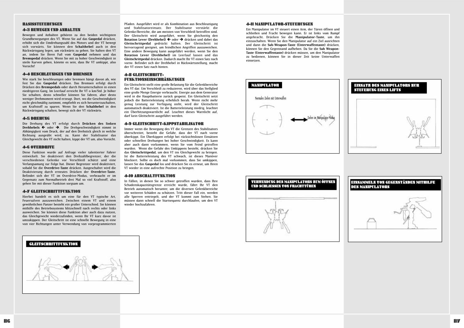
8786
BASISSTEUERUNGEN4-3 BEWEGEN UND ANHALTENBewegen und Anhalten gehören zu den beiden wichtigstenGrundbewegungen des VT. Wenn Sie auf das Gaspedal drücken,erhöht sich die Umdrehungszahl des Motors und der VT bewegtsich vorwärts. Sie können den Schalthebel auch in denRückwärtsgang legen, um rückwärts zu gehen. Sie halten den VTan, indem Sie Ihren Fuß vom Gaspedal nehmen und dasBremspedal drücken. Wenn Sie mit zu hoher Geschwindigkeit insteile Kurven gehen, könnte es sein, dass Ihr VT umkippt, alsoVorsicht!
4-4 BESCHLEUNIGEN UND BREMSENWie stark Sie beschleunigen oder bremsen hängt davon ab, wiefest Sie das Gaspedal drücken. Das Bremsen erfolgt durchDrücken des Bremspedals oder durch Herunterschalten in einenniedrigeren Gang. Im Leerlauf erreicht Ihr VT 0 km/Std. Je höherSie schalten, desto schneller können Sie fahren, aber destoweniger Drehmoment wird erzeugt. Dort, wo die Geschwindigkeitnicht gleichmäßig zunimmt, empfiehlt es sich herunterzuschalten,um Kraftstoff zu sparen. Wenn Sie den Schalthebel in denRückwärtsgang schalten, bewegt sich der VT rückwärts.
4-5 DREHUNGDie Drehung des VT erfolgt durch Drücken des linkenDrehhebels � oder �. Die Drehgeschwindigkeit nimmt inAbhängigkeit vom Druck, der auf den Drehstick gleich in welcheRichtung ausgeübt wird, zu. Kann der Stabilisator dasGleichgewicht des VT nicht halten, kippt der VT um, also Vorsicht.
4-6 OVERDRIVEDiese Funktion wurde auf Anfrage vieler talentierter Fahrerentwickelt. Sie deaktiviert den Drehzahlbegrenzer, der dieverschiedenen Gelenke vor Verschleiß schützt und eineVerlangsamung zur Folge hat. Dieser Begrenzer wird deaktiviert,sobald Sie die Overdrive-Taste drücken. Ausgeschaltet wird dieDeaktivierung durch erneutes Drücken der Overdrive-Taste.Befindet sich der VT im Overdrive-Modus, verbraucht er imGegensatz zum Normalbetrieb drei Mal so viel Kraftstoff, alsogehen Sie mit dieser Funktion sorgsam um.
4-7 GLEITSCHRITTFUNKTIONHierbei handelt es sich um eine für den VT typische Art,Feuersalven auszuweichen. Zwischen einem VT und einemgewöhnlichen Panzer besteht ein großer Unterschied. Sie könnenmithilfe des Betriebssystems blitzschnell nach rechts oder linksausweichen. Sie können diese Funktion aber auch dazu nutzen,das Gleichgewicht wiederzufinden, wenn Ihr VT kurz davor istumzukippen. Der Gleitschritt ist eine schnelle Bewegung in einevon vier Richtungen unter Verwendung von vorprogrammierten
Pfaden. Ausgeführt wird er als Kombination aus Beschleunigungund Stabilisatoreinsatz. Der Stabilisator verstärkt dieGelenke/Bereiche, die am meisten von Verschleiß betroffen sind.Der Gleitschritt wird ausgeführt, wenn Sie gleichzeitig denRotation Lever (Drehhebel) � oder � drücken und dabei dasGleitschrittpedal gedrückt halten. Der Gleitschritt isthervorragend geeignet, um feindlichen Angriffen auszuweichen.Eine andere Bewegung kann ausgeführt werden, wenn Sie denRotation Lever (Drehhebel) im Leerlauf lassen und dasGleitschrittpedal drücken. Dadurch macht Ihr VT einen Satz nachvorne. Befindet sich der Drehhebel in Rückwärtsstellung, machtder VT einen Satz nach hinten.
4-8 GLEITSCHRITT-FUNKTIONSEINSCHRÄNKUNGENEin Gleitschritt stellt eine große Belastung für die Gelenkbereichedes VT dar. Um Verschleiß zu reduzieren, wird über das Stellgliedeine große Menge Energie verbraucht. Energie aus dem Generatorwird in die Hauptbatterie zurück gespeist. Ein Gleitschritt setztjedoch die Batterieleistung erheblich herab. Wenn nicht mehrgenug Leistung zur Verfügung steht, wird der Gleitschrittautomatisch deaktiviert. Ist die Batterieleistung niedrig, leuchtetein Überhitzungswarnlicht auf. Leuchtet dieses Warnlicht auf,darf kein Gleitschritt ausgeführt werden.
4-9 GLEITSCHRITT-KIPPSTABILISATORImmer wenn die Bewegung des VT die Grenzen des Stabilisatorsüberschreitet, besteht die Gefahr, dass der VT nach vorneüberkippt. Ein Überkippen erfolgt bei rücksichtslosen Einsätzenoder schnellen Drehungen bei hoher Geschwindigkeit. Es kannaber auch dann vorkommen, wenn Sie vom Feind getroffenwurden. Wenn die Gefahr des Umkippens besteht, drücken Siedas Gleitschrittpedal, um den VT ins Gleichgewicht zu bringen.Ist die Batterieleistung des VT schwach, ist dieses Manöverblockiert. Sollte es doch mal vorkommen, dass Sie umkippen,lassen Sie das Gaspedal los und drücken Sie es erneut, um IhrenVT wieder in eine aufrechte Position zu bringen.
4-10 ABSCHALTFUNKTIONIn Fällen, in denen Sie so schwer getroffen wurden, dass IhreSchadenskapazitätsgrenze erreicht wurde, fährt Ihr VT denBetrieb automatisch herunter, um die diversen Gelenkbereichevor weiteren Schäden zu schützen. Tritt dieser Fall ein, werdenalle Sperren entriegelt, und der VT kommt zum Stehen. Siemüssen dann schnell die Startsequenz durchlaufen, um den VTwieder hochzufahren.
GLEITSCHRITTFUNKTION
4-11 MANIPULATOR-STEUERUNGENEin Manipulator im VT steuert einen Arm, der Türen öffnen undschließen und Fracht bewegen kann. Er ist links vom Rumpfangebracht. Drücken Sie die Manipulator-Taste, um ihneinzuschalten. Wenn Sie den Manipulator auf ein Ziel ausrichtenund dann die Sub-Weapon-Taste (Unterwaffentaste) drücken,können Sie den Gegenstand aufheben. Da Sie die Sub Weapon-Taste (Unterwaffentaste) drücken müssen, um den Manipulatorzu bedienen, können Sie in dieser Zeit keine Unterwaffeneinsetzen.
EINSATZ DES MANIPULATORS ZURSTEUERUNG EINES LIFTS
VERWENDUNG DES MANIPULATORS ZUM ÖFFNENUND SCHLIESSEN VON FRACHTTÜREN
MANIPULATOR
Normales Zielen mit Unterwaffen
Zielen im Manipulator-Modus
EINSAMMELN VON GEGENSTÄNDEN MITHILFEDES MANIPULATORS

8988
VT-MONITOR4-12 HAUPTKAMERAWECHSELDer Blickwinkel des VT wird von der Hauptkamera bestimmt.Dieses Bild wird ins Cockpit übertragen. Die Kamera istnormalerweise mittig nach vorne gerichtet. Durch Drücken desKnopfes auf dem linken Fahrerstick �, �, � oder � könnenSie das Sichtfeld vergrößern. Durch Drücken des Control Stick-Knopfes können Sie die Ansicht direkt auf die Mitte des VTzentrieren. Damit und mithilfe des VT-Sub-Monitors (wird späterbeschrieben) können Sie Ihren VT bewegen und seineEinsatzfähigkeit im Kampf verbessern.
4-13 HAUPTKAMERA SCHMUTZ UND STAUBBei Kampfeinsätzen müssen Sie eine klare Sicht auf demHauptschirm haben. Für den Fall, dass der Bildschirm durchSchmutz und Staub Grau wird, drücken Sie die Washing-Taste(Waschtaste), um ihn zu säubern.
KAMERAPERSPEKTIVEN
4-14 SUB-MONITOR-FUNKTIONENDurch Drücken der Sub-Monitor-Auswahltaste unter demHauptmonitor können Sie zwischen vier Modi wählen.
• Front View Mode (Modus Frontansicht)
Zeigt an, was sich direkt vor dem VT abspielt. Nutzen Siediese Ansicht zusammen mit derSchauplatzänderungsfunktion, um sich die Geschehnissegenauer anzusehen.
• Back View Mode (Modus Rückansicht)
Zeigt an, was sich direkt hinter dem VT abspielt. Wie bei derFrontansicht, kann auch diese Ansicht zusammen mit derSchauplatzänderungsfunktion genutzt werden, um sich dieGeschehnisse genauer anzusehen.
• Modus Zielerfassungsansicht
Zum Heranzoomen des erfassten Zieles. Ein sehr weitentferntes Ziel wird immer auf dem Sub-Monitor dargestellt,ohne dass es herangezoomt wird.
• Modus Vogelperspektive
In dieser Ansicht wird der VT aus einer Höhe von 50 Meternangezeigt. Diese Ansicht ist sehr nützlich für die Erkundungtoter Winkel und die genauere Begutachtung der Umgebungvon Objekten.
4-15 NACHTSICHTAUSRÜSTUNGDer VT ist mit einem Nachtsichtgerät ausgestattet, das selbst beischlechten Lichtverhältnissen bei Nacht oder in Umgebungen mitviel Nebel eine gute Sicht ermöglicht. Drücken Sie die NightScope-Taste (Nachtsichtgerättaste) auf der Bedientafel, um dasNachtsichtgerät zu aktivieren. Der VT nutzt einen so genanntenPassivlicht-JGVS-V442, der Infrarotlicht auf einen Gegenstandprojiziert und dann das Bild auf dem Bildschirm wiedergibt.Außerdem kann das Nachtsichtgerät nicht nur im Dunkeln oder innebliger Umgebung eingesetzt werden, sondern hilft auch bei derErkennung getarnter Ziele. Die Reichweite des Nachtsichtgerätsbeträgt bis zu 2,5 Kilometer. Die Ansicht wird auf dem normalenMonitor dargestellt. Wenn Sie das Nachtsichtgerät im Dunkelnverwenden, verursachen Lichtblitze des Kampfgeschehens oderinfolge einer explodierenden Granate eine vorübergehendeSchwarzfärbung des Nachtsichtgeräts, d. h. Sie könnenvorübergehend nichts erkennen.
JCS (Vollständiges Befehlssystem)4-16 JCS ZUSAMMENFASSUNGBei JCS handelt es sich um ein System, das strategischeKriegsdaten und die neuesten Informationen nutzt, um den VT soeffizient wie möglich einsetzen zu können. Hauptziel dabei ist es,die neuesten Informationen über den Kriegsschauplatz, eigeneTruppen, den Feind und andere Kompanien/Bataillone zusammeln. Das System wurde entwickelt, um dieGesamteffektivität des VT im Kampf zu verbessern. VT-Fahrer undPlatoon Commander müssen dieses Hilfsmittel beherrschen.
Das JCS bedient sich eines Netzwerks, das den VT-Transportkommandoraum und den Kommandoraum derverschiedenen Kompanien und Bataillone vernetzt, um so dierichtigen Personen mit den entsprechenden Informationen zuversorgen. Das System verschickt Meldungen der VT-Videomonitore, Aufklärungssatelliten und anderenKommandodivisionen und bearbeitet diese in Echtzeit in denKommandoräumen der Bataillone. Danach werden die Datenanalysiert und an die verschiedenen Platoons übermittelt. DieDaten werden über ein Funknetz an den VT übertragen und aufden verschiedenen Monitoren im Cockpit dargestellt. Dank diesesSystems können Fahrer die Karte prüfen, feindliche Stellungenausmachen und Waffenunterstützung für die Truppen anfordern.
KOMPLETTES BEFEHLSSYSTEMNETZWERK–TABELLARISCHE ZUSAMMENFASSUNG
VT-TransportbefehlszentraleVT
Aufklärungsjet
Aufklärungssatellit
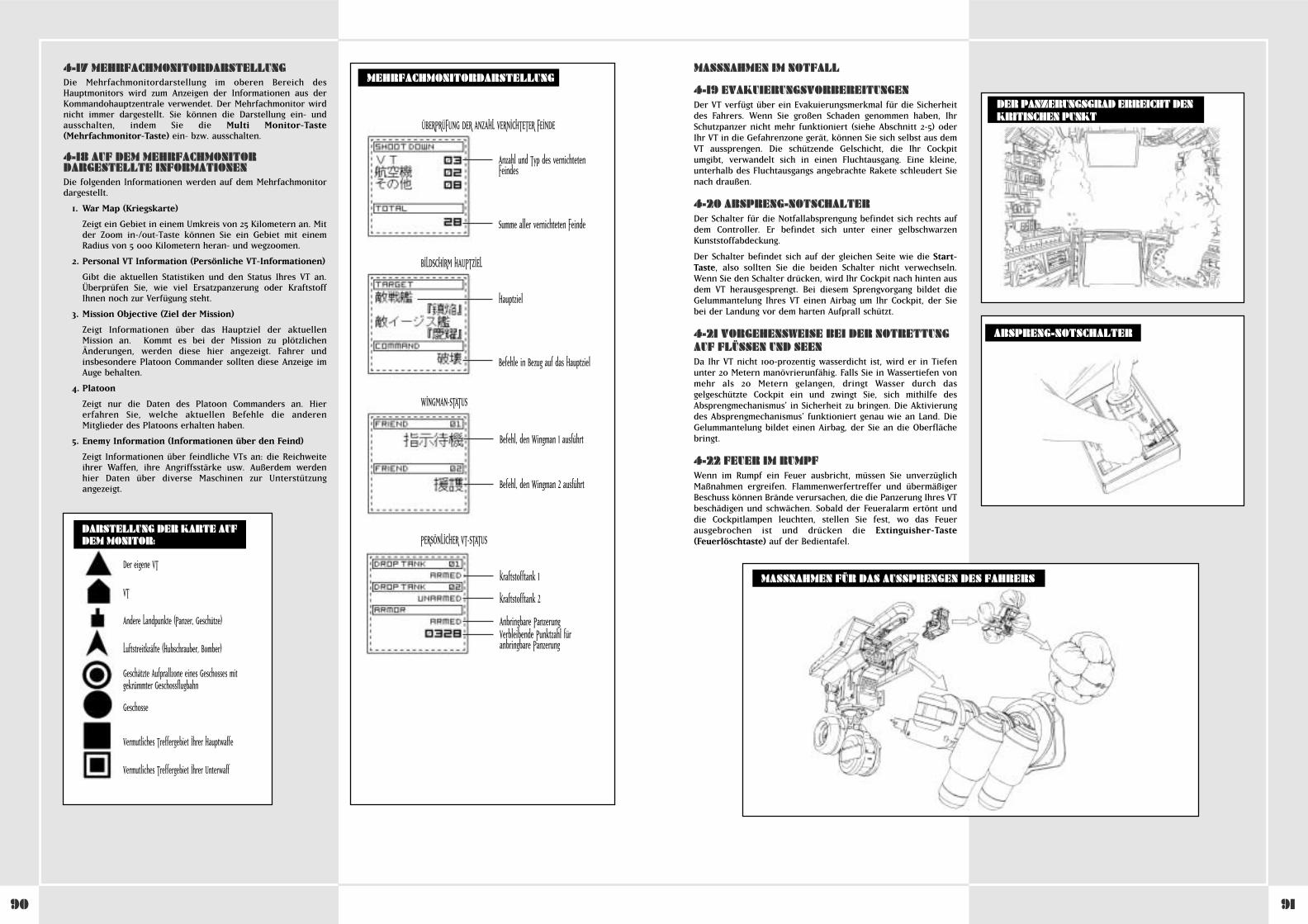
9190
4-17 MEHRFACHMONITORDARSTELLUNGDie Mehrfachmonitordarstellung im oberen Bereich desHauptmonitors wird zum Anzeigen der Informationen aus derKommandohauptzentrale verwendet. Der Mehrfachmonitor wirdnicht immer dargestellt. Sie können die Darstellung ein- undausschalten, indem Sie die Multi Monitor-Taste(Mehrfachmonitor-Taste) ein- bzw. ausschalten.
4-18 AUF DEM MEHRFACHMONITORDARGESTELLTE INFORMATIONENDie folgenden Informationen werden auf dem Mehrfachmonitordargestellt.
1. War Map (Kriegskarte)
Zeigt ein Gebiet in einem Umkreis von 25 Kilometern an. Mitder Zoom in-/out-Taste können Sie ein Gebiet mit einemRadius von 5 000 Kilometern heran- und wegzoomen.
2. Personal VT Information (Persönliche VT-Informationen)
Gibt die aktuellen Statistiken und den Status Ihres VT an.Überprüfen Sie, wie viel Ersatzpanzerung oder KraftstoffIhnen noch zur Verfügung steht.
3. Mission Objective (Ziel der Mission)
Zeigt Informationen über das Hauptziel der aktuellenMission an. Kommt es bei der Mission zu plötzlichenÄnderungen, werden diese hier angezeigt. Fahrer undinsbesondere Platoon Commander sollten diese Anzeige imAuge behalten.
4. Platoon
Zeigt nur die Daten des Platoon Commanders an. Hiererfahren Sie, welche aktuellen Befehle die anderenMitglieder des Platoons erhalten haben.
5. Enemy Information (Informationen über den Feind)
Zeigt Informationen über feindliche VTs an: die Reichweiteihrer Waffen, ihre Angriffsstärke usw. Außerdem werdenhier Daten über diverse Maschinen zur Unterstützungangezeigt.
MEHRFACHMONITORDARSTELLUNG
ÜBERPRÜFUNG DER ANZAHL VERNICHTETER FEINDE
Anzahl und Typ des vernichtetenFeindes
Summe aller vernichteten Feinde
Hauptziel
Befehle in Bezug auf das Hauptziel
BILDSCHIRM HAUPTZIEL
Befehl, den Wingman 1 ausführt
Befehl, den Wingman 2 ausführt
WINGMAN-STATUS
Kraftstofftank 1
Kraftstofftank 2
Anbringbare PanzerungVerbleibende Punktzahl füranbringbare Panzerung
PERSÖNLICHER VT-STATUS
Der eigene VT
VT
Andere Landpunkte (Panzer, Geschütze)
Luftstreitkräfte (Hubschrauber, Bomber)
Geschätzte Aufprallzone eines Geschosses mit gekrümmter Geschossflugbahn
Geschosse
Vermutliches Treffergebiet Ihrer Hauptwaffe
Vermutliches Treffergebiet Ihrer Unterwaff
DARSTELLUNG DER KARTE AUF DEM MONITOR:
MASSNAHMEN IM NOTFALL
4-19 EVAKUIERUNGSVORBEREITUNGENDer VT verfügt über ein Evakuierungsmerkmal für die Sicherheitdes Fahrers. Wenn Sie großen Schaden genommen haben, IhrSchutzpanzer nicht mehr funktioniert (siehe Abschnitt 2-5) oderIhr VT in die Gefahrenzone gerät, können Sie sich selbst aus demVT aussprengen. Die schützende Gelschicht, die Ihr Cockpitumgibt, verwandelt sich in einen Fluchtausgang. Eine kleine,unterhalb des Fluchtausgangs angebrachte Rakete schleudert Sienach draußen.
4-20 ABSPRENG-NOTSCHALTERDer Schalter für die Notfallabsprengung befindet sich rechts aufdem Controller. Er befindet sich unter einer gelbschwarzenKunststoffabdeckung.
Der Schalter befindet sich auf der gleichen Seite wie die Start-Taste, also sollten Sie die beiden Schalter nicht verwechseln.Wenn Sie den Schalter drücken, wird Ihr Cockpit nach hinten ausdem VT herausgesprengt. Bei diesem Sprengvorgang bildet dieGelummantelung Ihres VT einen Airbag um Ihr Cockpit, der Siebei der Landung vor dem harten Aufprall schützt.
4-21 VORGEHENSWEISE BEI DER NOTRETTUNGAUF FLÜSSEN UND SEENDa Ihr VT nicht 100-prozentig wasserdicht ist, wird er in Tiefenunter 20 Metern manövrierunfähig. Falls Sie in Wassertiefen vonmehr als 20 Metern gelangen, dringt Wasser durch dasgelgeschützte Cockpit ein und zwingt Sie, sich mithilfe desAbsprengmechanismus’ in Sicherheit zu bringen. Die Aktivierungdes Absprengmechanismus’ funktioniert genau wie an Land. DieGelummantelung bildet einen Airbag, der Sie an die Oberflächebringt.
4-22 FEUER IM RUMPFWenn im Rumpf ein Feuer ausbricht, müssen Sie unverzüglichMaßnahmen ergreifen. Flammenwerfertreffer und übermäßigerBeschuss können Brände verursachen, die die Panzerung Ihres VTbeschädigen und schwächen. Sobald der Feueralarm ertönt unddie Cockpitlampen leuchten, stellen Sie fest, wo das Feuerausgebrochen ist und drücken die Extinguisher-Taste(Feuerlöschtaste) auf der Bedientafel.
ABSPRENG-NOTSCHALTER
MASSNAHMEN FÜR DAS AUSSPRENGEN DES FAHRERS
DER PANZERUNGSGRAD ERREICHT DENKRITISCHEN PUNKT
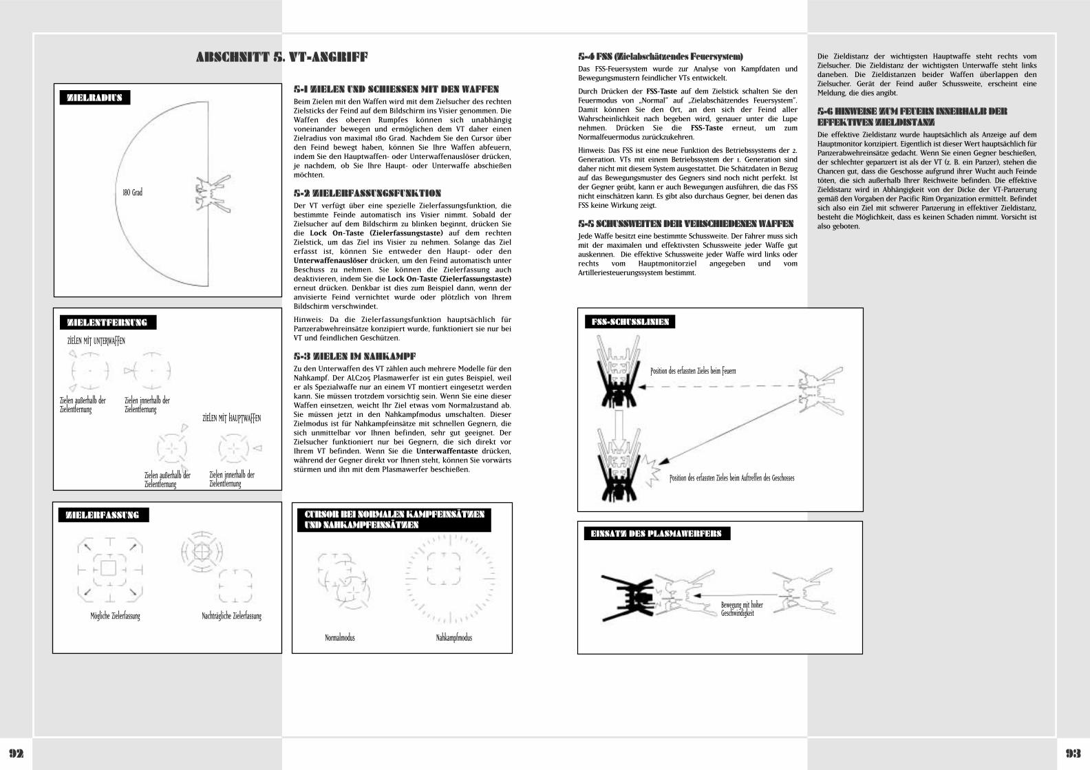
9392
5-1 ZIELEN UND SCHIESSEN MIT DEN WAFFENBeim Zielen mit den Waffen wird mit dem Zielsucher des rechtenZielsticks der Feind auf dem Bildschirm ins Visier genommen. DieWaffen des oberen Rumpfes können sich unabhängigvoneinander bewegen und ermöglichen dem VT daher einenZielradius von maximal 180 Grad. Nachdem Sie den Cursor überden Feind bewegt haben, können Sie Ihre Waffen abfeuern,indem Sie den Hauptwaffen- oder Unterwaffenauslöser drücken,je nachdem, ob Sie Ihre Haupt- oder Unterwaffe abschießenmöchten.
5-2 ZIELERFASSUNGSFUNKTIONDer VT verfügt über eine spezielle Zielerfassungsfunktion, diebestimmte Feinde automatisch ins Visier nimmt. Sobald derZielsucher auf dem Bildschirm zu blinken beginnt, drücken Siedie Lock On-Taste (Zielerfassungstaste) auf dem rechtenZielstick, um das Ziel ins Visier zu nehmen. Solange das Zielerfasst ist, können Sie entweder den Haupt- oder denUnterwaffenauslöser drücken, um den Feind automatisch unterBeschuss zu nehmen. Sie können die Zielerfassung auchdeaktivieren, indem Sie die Lock On-Taste (Zielerfassungstaste)erneut drücken. Denkbar ist dies zum Beispiel dann, wenn deranvisierte Feind vernichtet wurde oder plötzlich von IhremBildschirm verschwindet.
Hinweis: Da die Zielerfassungsfunktion hauptsächlich fürPanzerabwehreinsätze konzipiert wurde, funktioniert sie nur beiVT und feindlichen Geschützen.
5-3 ZIELEN IM NAHKAMPFZu den Unterwaffen des VT zählen auch mehrere Modelle für denNahkampf. Der ALC205 Plasmawerfer ist ein gutes Beispiel, weiler als Spezialwaffe nur an einem VT montiert eingesetzt werdenkann. Sie müssen trotzdem vorsichtig sein. Wenn Sie eine dieserWaffen einsetzen, weicht Ihr Ziel etwas vom Normalzustand ab.Sie müssen jetzt in den Nahkampfmodus umschalten. DieserZielmodus ist für Nahkampfeinsätze mit schnellen Gegnern, diesich unmittelbar vor Ihnen befinden, sehr gut geeignet. DerZielsucher funktioniert nur bei Gegnern, die sich direkt vorIhrem VT befinden. Wenn Sie die Unterwaffentaste drücken,während der Gegner direkt vor Ihnen steht, können Sie vorwärtsstürmen und ihn mit dem Plasmawerfer beschießen.
ABSCHNITT 5. VT-ANGRIFF
ZIELERFASSUNG
ZIELRADIUS
ZIELENTFERNUNG
180 Grad
ZIELEN MIT UNTERWAFFEN
Zielen außerhalb derZielentfernung
Zielen innerhalb derZielentfernung
ZIELEN MIT HAUPTWAFFEN
Zielen außerhalb derZielentfernung
Zielen innerhalb derZielentfernung
Mögliche Zielerfassung Nachträgliche Zielerfassung
CURSOR BEI NORMALEN KAMPFEINSÄTZENUND NAHKAMPFEINSÄTZEN
Normalmodus Nahkampfmodus
5-4 FSS (Zielabschätzendes Feuersystem)Das FSS-Feuersystem wurde zur Analyse von Kampfdaten undBewegungsmustern feindlicher VTs entwickelt.
Durch Drücken der FSS-Taste auf dem Zielstick schalten Sie denFeuermodus von „Normal” auf „Zielabschätzendes Feuersystem”.Damit können Sie den Ort, an den sich der Feind allerWahrscheinlichkeit nach begeben wird, genauer unter die Lupenehmen. Drücken Sie die FSS-Taste erneut, um zumNormalfeuermodus zurückzukehren.
Hinweis: Das FSS ist eine neue Funktion des Betriebssystems der 2.Generation. VTs mit einem Betriebssystem der 1. Generation sinddaher nicht mit diesem System ausgestattet. Die Schätzdaten in Bezugauf das Bewegungsmuster des Gegners sind noch nicht perfekt. Istder Gegner geübt, kann er auch Bewegungen ausführen, die das FSSnicht einschätzen kann. Es gibt also durchaus Gegner, bei denen dasFSS keine Wirkung zeigt.
5-5 SCHUSSWEITEN DER VERSCHIEDENEN WAFFENJede Waffe besitzt eine bestimmte Schussweite. Der Fahrer muss sichmit der maximalen und effektivsten Schussweite jeder Waffe gutauskennen. Die effektive Schussweite jeder Waffe wird links oderrechts vom Hauptmonitorziel angegeben und vomArtilleriesteuerungssystem bestimmt.
Die Zieldistanz der wichtigsten Hauptwaffe steht rechts vomZielsucher. Die Zieldistanz der wichtigsten Unterwaffe steht linksdaneben. Die Zieldistanzen beider Waffen überlappen denZielsucher. Gerät der Feind außer Schussweite, erscheint eineMeldung, die dies angibt.
5-6 HINWEISE ZUM FEUERN INNERHALB DEREFFEKTIVEN ZIELDISTANZDie effektive Zieldistanz wurde hauptsächlich als Anzeige auf demHauptmonitor konzipiert. Eigentlich ist dieser Wert hauptsächlich fürPanzerabwehreinsätze gedacht. Wenn Sie einen Gegner beschießen,der schlechter gepanzert ist als der VT (z. B. ein Panzer), stehen dieChancen gut, dass die Geschosse aufgrund ihrer Wucht auch Feindetöten, die sich außerhalb Ihrer Reichweite befinden. Die effektiveZieldistanz wird in Abhängigkeit von der Dicke der VT-Panzerunggemäß den Vorgaben der Pacific Rim Organization ermittelt. Befindetsich also ein Ziel mit schwerer Panzerung in effektiver Zieldistanz,besteht die Möglichkeit, dass es keinen Schaden nimmt. Vorsicht istalso geboten.
EINSATZ DES PLASMAWERFERS
Bewegung mit hoherGeschwindigkeit
FSS-SCHUSSLINIEN
Position des erfassten Zieles beim Feuern
Position des erfassten Zieles beim Auftreffen des Geschosses
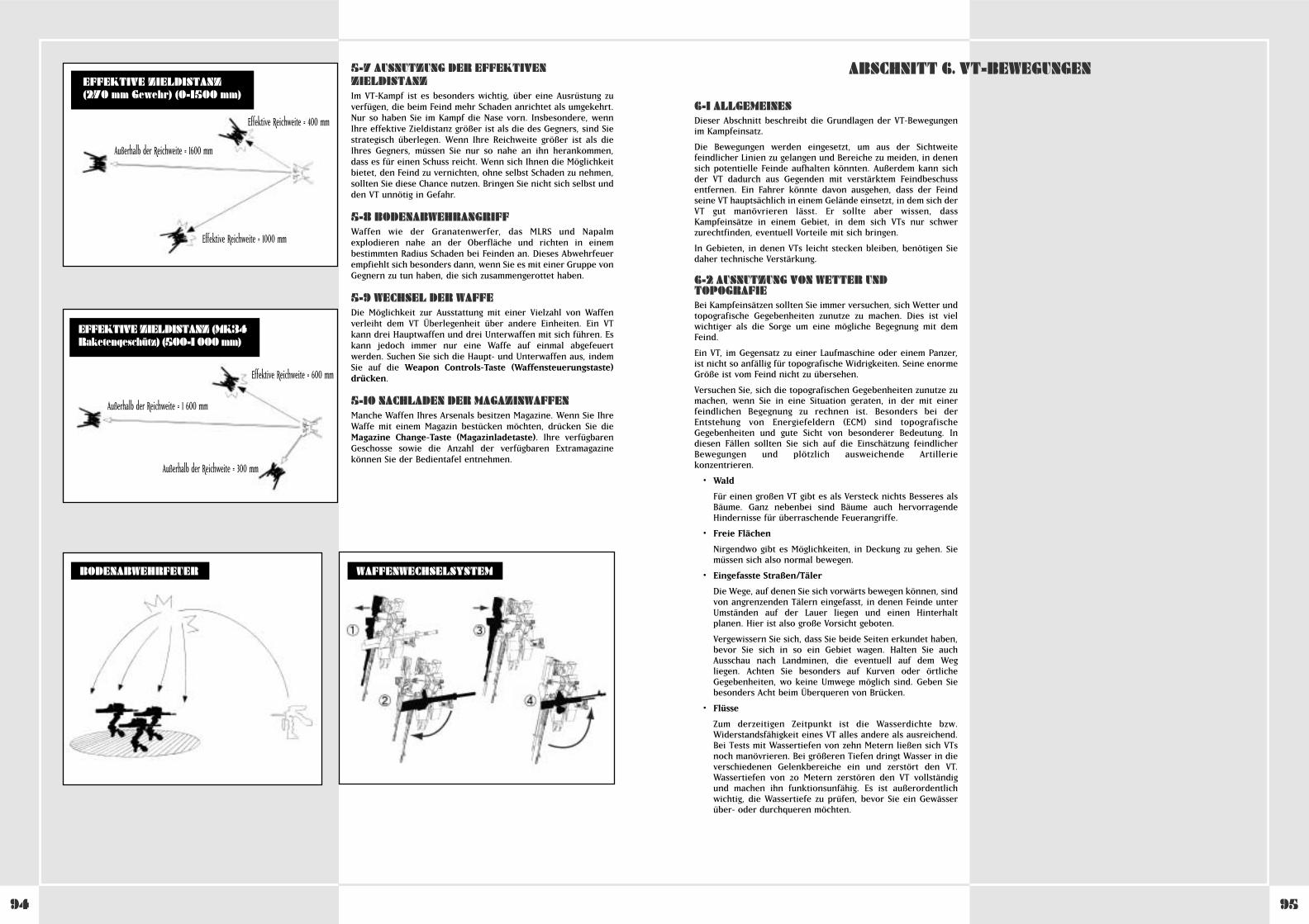
9594
WAFFENWECHSELSYSTEMBODENABWEHRFEUER
Effektive Reichweite = 400 mm
Effektive Reichweite = 1000 mm
Außerhalb der Reichweite = 1600 mm
EFFEKTIVE ZIELDISTANZ(270 mm Gewehr) (0-1500 mm)
EFFEKTIVE ZIELDISTANZ (MK34Raketengeschütz) (500-1 000 mm)
Effektive Reichweite = 600 mm
Außerhalb der Reichweite = 1 600 mm
Außerhalb der Reichweite = 300 mm
5-7 AUSNUTZUNG DER EFFEKTIVENZIELDISTANZIm VT-Kampf ist es besonders wichtig, über eine Ausrüstung zuverfügen, die beim Feind mehr Schaden anrichtet als umgekehrt.Nur so haben Sie im Kampf die Nase vorn. Insbesondere, wennIhre effektive Zieldistanz größer ist als die des Gegners, sind Siestrategisch überlegen. Wenn Ihre Reichweite größer ist als dieIhres Gegners, müssen Sie nur so nahe an ihn herankommen,dass es für einen Schuss reicht. Wenn sich Ihnen die Möglichkeitbietet, den Feind zu vernichten, ohne selbst Schaden zu nehmen,sollten Sie diese Chance nutzen. Bringen Sie nicht sich selbst undden VT unnötig in Gefahr.
5-8 BODENABWEHRANGRIFFWaffen wie der Granatenwerfer, das MLRS und Napalmexplodieren nahe an der Oberfläche und richten in einembestimmten Radius Schaden bei Feinden an. Dieses Abwehrfeuerempfiehlt sich besonders dann, wenn Sie es mit einer Gruppe vonGegnern zu tun haben, die sich zusammengerottet haben.
5-9 WECHSEL DER WAFFEDie Möglichkeit zur Ausstattung mit einer Vielzahl von Waffenverleiht dem VT Überlegenheit über andere Einheiten. Ein VTkann drei Hauptwaffen und drei Unterwaffen mit sich führen. Eskann jedoch immer nur eine Waffe auf einmal abgefeuertwerden. Suchen Sie sich die Haupt- und Unterwaffen aus, indemSie auf die Weapon Controls-Taste (Waffensteuerungstaste)drücken.
5-10 NACHLADEN DER MAGAZINWAFFENManche Waffen Ihres Arsenals besitzen Magazine. Wenn Sie IhreWaffe mit einem Magazin bestücken möchten, drücken Sie dieMagazine Change-Taste (Magazinladetaste). Ihre verfügbarenGeschosse sowie die Anzahl der verfügbaren Extramagazinekönnen Sie der Bedientafel entnehmen.
6-1 ALLGEMEINESDieser Abschnitt beschreibt die Grundlagen der VT-Bewegungenim Kampfeinsatz.
Die Bewegungen werden eingesetzt, um aus der Sichtweitefeindlicher Linien zu gelangen und Bereiche zu meiden, in denensich potentielle Feinde aufhalten könnten. Außerdem kann sichder VT dadurch aus Gegenden mit verstärktem Feindbeschussentfernen. Ein Fahrer könnte davon ausgehen, dass der Feindseine VT hauptsächlich in einem Gelände einsetzt, in dem sich derVT gut manövrieren lässt. Er sollte aber wissen, dassKampfeinsätze in einem Gebiet, in dem sich VTs nur schwerzurechtfinden, eventuell Vorteile mit sich bringen.
In Gebieten, in denen VTs leicht stecken bleiben, benötigen Siedaher technische Verstärkung.
6-2 AUSNUTZUNG VON WETTER UNDTOPOGRAFIEBei Kampfeinsätzen sollten Sie immer versuchen, sich Wetter undtopografische Gegebenheiten zunutze zu machen. Dies ist vielwichtiger als die Sorge um eine mögliche Begegnung mit demFeind.
Ein VT, im Gegensatz zu einer Laufmaschine oder einem Panzer,ist nicht so anfällig für topografische Widrigkeiten. Seine enormeGröße ist vom Feind nicht zu übersehen.
Versuchen Sie, sich die topografischen Gegebenheiten zunutze zumachen, wenn Sie in eine Situation geraten, in der mit einerfeindlichen Begegnung zu rechnen ist. Besonders bei derEntstehung von Energiefeldern (ECM) sind topografischeGegebenheiten und gute Sicht von besonderer Bedeutung. Indiesen Fällen sollten Sie sich auf die Einschätzung feindlicherBewegungen und plötzlich ausweichende Artilleriekonzentrieren.
• Wald
Für einen großen VT gibt es als Versteck nichts Besseres alsBäume. Ganz nebenbei sind Bäume auch hervorragendeHindernisse für überraschende Feuerangriffe.
• Freie Flächen
Nirgendwo gibt es Möglichkeiten, in Deckung zu gehen. Siemüssen sich also normal bewegen.
• Eingefasste Straßen/Täler
Die Wege, auf denen Sie sich vorwärts bewegen können, sindvon angrenzenden Tälern eingefasst, in denen Feinde unterUmständen auf der Lauer liegen und einen Hinterhaltplanen. Hier ist also große Vorsicht geboten.
Vergewissern Sie sich, dass Sie beide Seiten erkundet haben,bevor Sie sich in so ein Gebiet wagen. Halten Sie auchAusschau nach Landminen, die eventuell auf dem Wegliegen. Achten Sie besonders auf Kurven oder örtlicheGegebenheiten, wo keine Umwege möglich sind. Geben Siebesonders Acht beim Überqueren von Brücken.
• Flüsse
Zum derzeitigen Zeitpunkt ist die Wasserdichte bzw.Widerstandsfähigkeit eines VT alles andere als ausreichend.Bei Tests mit Wassertiefen von zehn Metern ließen sich VTsnoch manövrieren. Bei größeren Tiefen dringt Wasser in dieverschiedenen Gelenkbereiche ein und zerstört den VT.Wassertiefen von 20 Metern zerstören den VT vollständigund machen ihn funktionsunfähig. Es ist außerordentlichwichtig, die Wassertiefe zu prüfen, bevor Sie ein Gewässerüber- oder durchqueren möchten.
ABSCHNITT 6. VT-BEWEGUNGEN
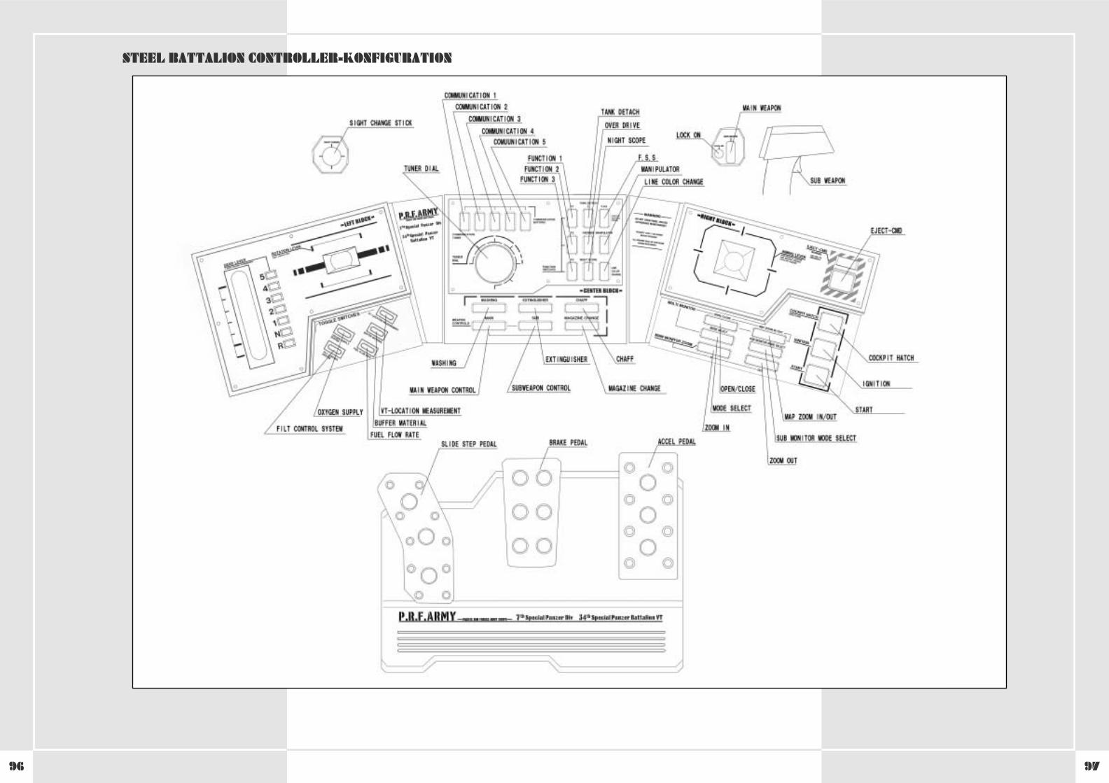
9796
STEEL BATTALION CONTROLLER-KONFIGURATION
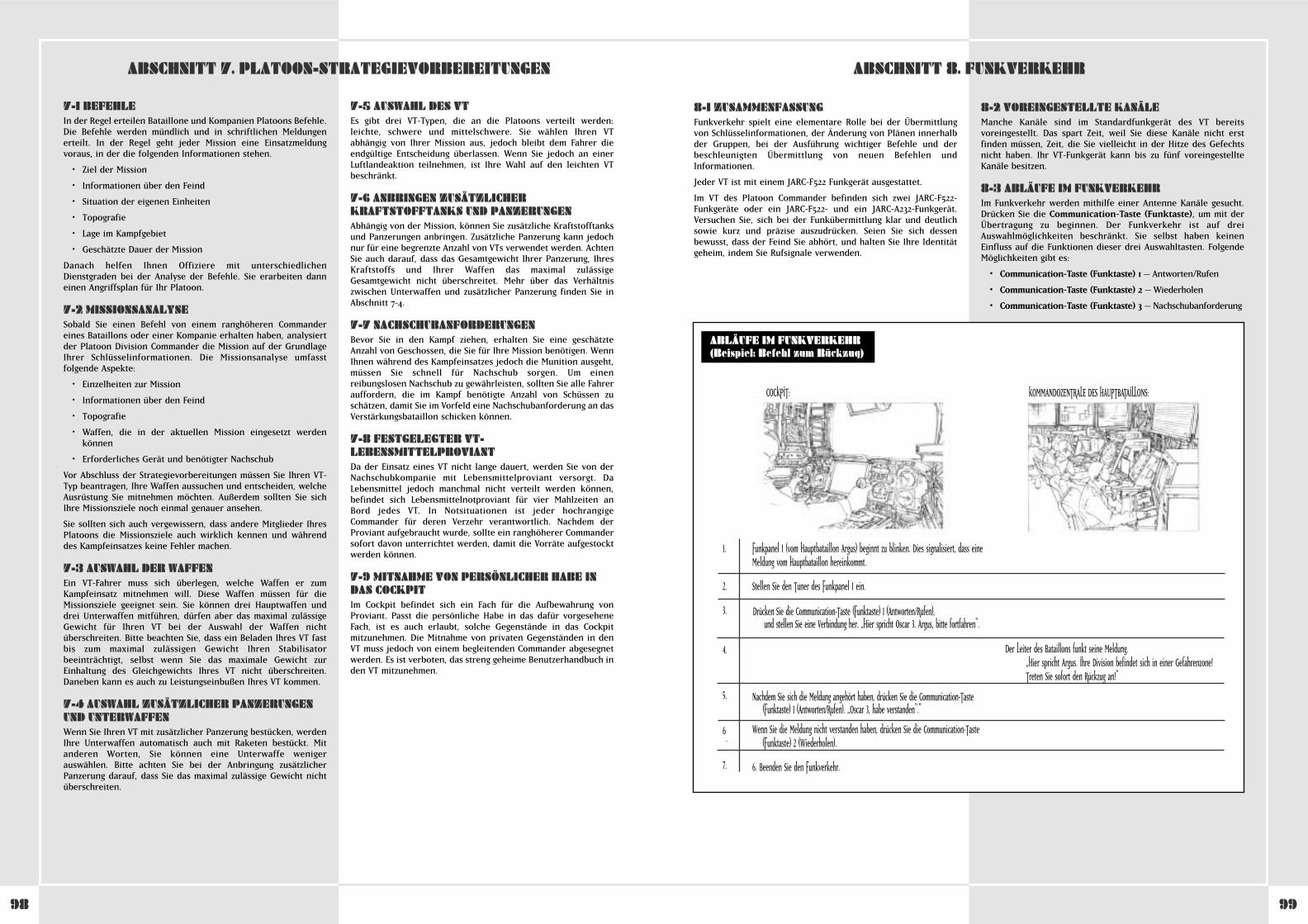
9998
8-1 ZUSAMMENFASSUNGFunkverkehr spielt eine elementare Rolle bei der Übermittlungvon Schlüsselinformationen, der Änderung von Plänen innerhalbder Gruppen, bei der Ausführung wichtiger Befehle und derbeschleunigten Übermittlung von neuen Befehlen undInformationen.
Jeder VT ist mit einem JARC-F522 Funkgerät ausgestattet.
Im VT des Platoon Commander befinden sich zwei JARC-F522-Funkgeräte oder ein JARC-F522- und ein JARC-A232-Funkgerät.Versuchen Sie, sich bei der Funkübermittlung klar und deutlichsowie kurz und präzise auszudrücken. Seien Sie sich dessenbewusst, dass der Feind Sie abhört, und halten Sie Ihre Identitätgeheim, indem Sie Rufsignale verwenden.
8-2 VOREINGESTELLTE KANÄLEManche Kanäle sind im Standardfunkgerät des VT bereitsvoreingestellt. Das spart Zeit, weil Sie diese Kanäle nicht erstfinden müssen, Zeit, die Sie vielleicht in der Hitze des Gefechtsnicht haben. Ihr VT-Funkgerät kann bis zu fünf voreingestellteKanäle besitzen.
8-3 ABLÄUFE IM FUNKVERKEHRIm Funkverkehr werden mithilfe einer Antenne Kanäle gesucht.Drücken Sie die Communication-Taste (Funktaste), um mit derÜbertragung zu beginnen. Der Funkverkehr ist auf dreiAuswahlmöglichkeiten beschränkt. Sie selbst haben keinenEinfluss auf die Funktionen dieser drei Auswahltasten. FolgendeMöglichkeiten gibt es:
• Communication-Taste (Funktaste) 1 – Antworten/Rufen
• Communication-Taste (Funktaste) 2 – Wiederholen
• Communication-Taste (Funktaste) 3 – Nachschubanforderung
ABSCHNITT 8. FUNKVERKEHR
1. Communication panel 1 (from the main battalion Argus) begins to flash.This signals that a message from the main battalion is coming in.
2. Set the tuner on Communications Panel 1.
3. Press Communication Button 1 (respond/call) and open a connection.
"This is Oscar 3. Argus, go ahead."
Der Leiter des Bataillons funkt seine Meldung.„Hier spricht Argus. Ihre Division befindet sich in einer Gefahrenzone!Treten Sie sofort den Rückzug an!“
If you didn’t hear the message, press Communication Button 2 (repeat).
ABLÄUFE IM FUNKVERKEHR(Beispiel: Befehl zum Rückzug)
COCKPIT: KOMMANDOZENTRALE DES HAUPTBATAILLONS:
1. Communication panel 1 (from the main battalion Argus) begins to flash.This signals that a message from the main battalion is coming in.
2. Set the tuner on Communications Panel 1.
3. Press Communication Button 1 (respond/call) and open a connection.
"This is Oscar 3. Argus, go ahead."
4. The battalion head gives his message.
"This is Argus. Your division is in a bad spot! Retreat immediately!"
5. After you hear what was said, press Communication Button 1 "
6. If you didn’t hear the message, press Communication Button 2 (repeat).
7. Finish the communication.
Funkpanel 1 (vom Hauptbataillon Argus) beginnt zu blinken. Dies signalisiert, dass eineMeldung vom Hauptbataillon hereinkommt.
Stellen Sie den Tuner des Funkpanel 1 ein.
Drücken Sie die Communication-Taste (Funktaste) 1 (Antworten/Rufen), und stellen Sie eine Verbindung her. „Hier spricht Oscar 3. Argus, bitte fortfahren“.
4. The battalion head gives his message.
"This is Argus. Your division is in a bad spot! Retreat immediately!"
Nachdem Sie sich die Meldung angehört haben, drücken Sie die Communication-Taste(Funktaste) 1 (Antworten/Rufen). „Oscar 3, habe verstanden“."
Wenn Sie die Meldung nicht verstanden haben, drücken Sie die Communication-Taste(Funktaste) 2 (Wiederholen).
6. Beenden Sie den Funkverkehr.
7-1 BEFEHLEIn der Regel erteilen Bataillone und Kompanien Platoons Befehle.Die Befehle werden mündlich und in schriftlichen Meldungenerteilt. In der Regel geht jeder Mission eine Einsatzmeldungvoraus, in der die folgenden Informationen stehen.
• Ziel der Mission
• Informationen über den Feind
• Situation der eigenen Einheiten
• Topografie
• Lage im Kampfgebiet
• Geschätzte Dauer der Mission
Danach helfen Ihnen Offiziere mit unterschiedlichenDienstgraden bei der Analyse der Befehle. Sie erarbeiten danneinen Angriffsplan für Ihr Platoon.
7-2 MISSIONSANALYSESobald Sie einen Befehl von einem ranghöheren Commandereines Bataillons oder einer Kompanie erhalten haben, analysiertder Platoon Division Commander die Mission auf der GrundlageIhrer Schlüsselinformationen. Die Missionsanalyse umfasstfolgende Aspekte:
• Einzelheiten zur Mission
• Informationen über den Feind
• Topografie
• Waffen, die in der aktuellen Mission eingesetzt werdenkönnen
• Erforderliches Gerät und benötigter Nachschub
Vor Abschluss der Strategievorbereitungen müssen Sie Ihren VT-Typ beantragen, Ihre Waffen aussuchen und entscheiden, welcheAusrüstung Sie mitnehmen möchten. Außerdem sollten Sie sichIhre Missionsziele noch einmal genauer ansehen.
Sie sollten sich auch vergewissern, dass andere Mitglieder IhresPlatoons die Missionsziele auch wirklich kennen und währenddes Kampfeinsatzes keine Fehler machen.
7-3 AUSWAHL DER WAFFENEin VT-Fahrer muss sich überlegen, welche Waffen er zumKampfeinsatz mitnehmen will. Diese Waffen müssen für dieMissionsziele geeignet sein. Sie können drei Hauptwaffen unddrei Unterwaffen mitführen, dürfen aber das maximal zulässigeGewicht für Ihren VT bei der Auswahl der Waffen nichtüberschreiten. Bitte beachten Sie, dass ein Beladen Ihres VT fastbis zum maximal zulässigen Gewicht Ihren Stabilisatorbeeinträchtigt, selbst wenn Sie das maximale Gewicht zurEinhaltung des Gleichgewichts Ihres VT nicht überschreiten.Daneben kann es auch zu Leistungseinbußen Ihres VT kommen.
7-4 AUSWAHL ZUSÄTZLICHER PANZERUNGENUND UNTERWAFFENWenn Sie Ihren VT mit zusätzlicher Panzerung bestücken, werdenIhre Unterwaffen automatisch auch mit Raketen bestückt. Mitanderen Worten, Sie können eine Unterwaffe wenigerauswählen. Bitte achten Sie bei der Anbringung zusätzlicherPanzerung darauf, dass Sie das maximal zulässige Gewicht nichtüberschreiten.
7-5 AUSWAHL DES VTEs gibt drei VT-Typen, die an die Platoons verteilt werden:leichte, schwere und mittelschwere. Sie wählen Ihren VTabhängig von Ihrer Mission aus, jedoch bleibt dem Fahrer dieendgültige Entscheidung überlassen. Wenn Sie jedoch an einerLuftlandeaktion teilnehmen, ist Ihre Wahl auf den leichten VTbeschränkt.
7-6 ANBRINGEN ZUSÄTZLICHERKRAFTSTOFFTANKS UND PANZERUNGENAbhängig von der Mission, können Sie zusätzliche Kraftstofftanksund Panzerungen anbringen. Zusätzliche Panzerung kann jedochnur für eine begrenzte Anzahl von VTs verwendet werden. AchtenSie auch darauf, dass das Gesamtgewicht Ihrer Panzerung, IhresKraftstoffs und Ihrer Waffen das maximal zulässigeGesamtgewicht nicht überschreitet. Mehr über das Verhältniszwischen Unterwaffen und zusätzlicher Panzerung finden Sie inAbschnitt 7-4.
7-7 NACHSCHUBANFORDERUNGENBevor Sie in den Kampf ziehen, erhalten Sie eine geschätzteAnzahl von Geschossen, die Sie für Ihre Mission benötigen. WennIhnen während des Kampfeinsatzes jedoch die Munition ausgeht,müssen Sie schnell für Nachschub sorgen. Um einenreibungslosen Nachschub zu gewährleisten, sollten Sie alle Fahrerauffordern, die im Kampf benötigte Anzahl von Schüssen zuschätzen, damit Sie im Vorfeld eine Nachschubanforderung an dasVerstärkungsbataillon schicken können.
7-8 FESTGELEGTER VT-LEBENSMITTELPROVIANTDa der Einsatz eines VT nicht lange dauert, werden Sie von derNachschubkompanie mit Lebensmittelproviant versorgt. DaLebensmittel jedoch manchmal nicht verteilt werden können,befindet sich Lebensmittelnotproviant für vier Mahlzeiten anBord jedes VT. In Notsituationen ist jeder hochrangigeCommander für deren Verzehr verantwortlich. Nachdem derProviant aufgebraucht wurde, sollte ein ranghöherer Commandersofort davon unterrichtet werden, damit die Vorräte aufgestocktwerden können.
7-9 MITNAHME VON PERSÖNLICHER HABE INDAS COCKPITIm Cockpit befindet sich ein Fach für die Aufbewahrung vonProviant. Passt die persönliche Habe in das dafür vorgeseheneFach, ist es auch erlaubt, solche Gegenstände in das Cockpitmitzunehmen. Die Mitnahme von privaten Gegenständen in denVT muss jedoch von einem begleitenden Commander abgesegnetwerden. Es ist verboten, das streng geheime Benutzerhandbuch inden VT mitzunehmen.
ABSCHNITT 7. PLATOON-STRATEGIEVORBEREITUNGEN
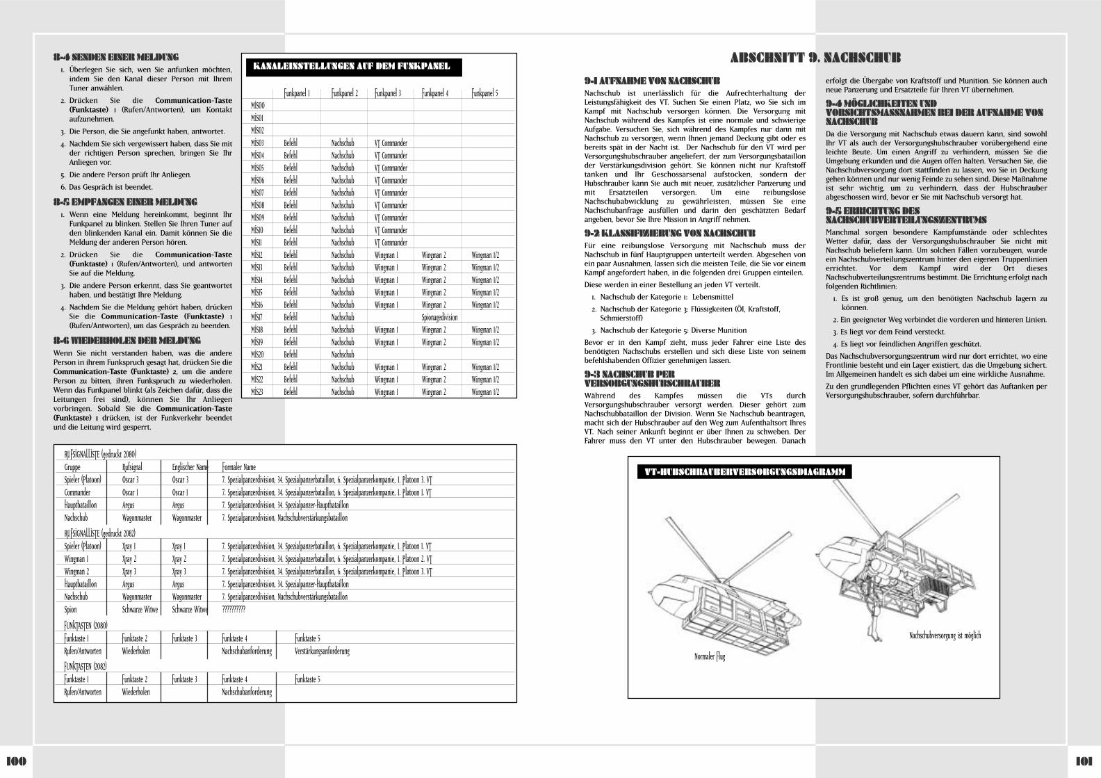
101100
9-1 AUFNAHME VON NACHSCHUBNachschub ist unerlässlich für die Aufrechterhaltung derLeistungsfähigkeit des VT. Suchen Sie einen Platz, wo Sie sich imKampf mit Nachschub versorgen können. Die Versorgung mitNachschub während des Kampfes ist eine normale und schwierigeAufgabe. Versuchen Sie, sich während des Kampfes nur dann mitNachschub zu versorgen, wenn Ihnen jemand Deckung gibt oder esbereits spät in der Nacht ist. Der Nachschub für den VT wird perVersorgungshubschrauber angeliefert, der zum Versorgungsbataillonder Verstärkungsdivision gehört. Sie können nicht nur Kraftstofftanken und Ihr Geschossarsenal aufstocken, sondern derHubschrauber kann Sie auch mit neuer, zusätzlicher Panzerung undmit Ersatzteilen versorgen. Um eine reibungsloseNachschubabwicklung zu gewährleisten, müssen Sie eineNachschubanfrage ausfüllen und darin den geschätzten Bedarfangeben, bevor Sie Ihre Mission in Angriff nehmen.
9-2 KLASSIFIZIERUNG VON NACHSCHUBFür eine reibungslose Versorgung mit Nachschub muss derNachschub in fünf Hauptgruppen unterteilt werden. Abgesehen vonein paar Ausnahmen, lassen sich die meisten Teile, die Sie vor einemKampf angefordert haben, in die folgenden drei Gruppen einteilen.
Diese werden in einer Bestellung an jeden VT verteilt.
1. Nachschub der Kategorie 1: Lebensmittel
2. Nachschub der Kategorie 3: Flüssigkeiten (Öl, Kraftstoff, Schmierstoff)
3. Nachschub der Kategorie 5: Diverse Munition
Bevor er in den Kampf zieht, muss jeder Fahrer eine Liste desbenötigten Nachschubs erstellen und sich diese Liste von seinembefehlshabenden Offizier genehmigen lassen.
9-3 NACHSCHUB PERVERSORGUNGSHUBSCHRAUBERWährend des Kampfes müssen die VTs durchVersorgungshubschrauber versorgt werden. Dieser gehört zumNachschubbataillon der Division. Wenn Sie Nachschub beantragen,macht sich der Hubschrauber auf den Weg zum Aufenthaltsort IhresVT. Nach seiner Ankunft beginnt er über Ihnen zu schweben. DerFahrer muss den VT unter den Hubschrauber bewegen. Danach
erfolgt die Übergabe von Kraftstoff und Munition. Sie können auchneue Panzerung und Ersatzteile für Ihren VT übernehmen.
9-4 MÖGLICHKEITEN UNDVORSICHTSMASSNAHMEN BEI DER AUFNAHME VONNACHSCHUBDa die Versorgung mit Nachschub etwas dauern kann, sind sowohlIhr VT als auch der Versorgungshubschrauber vorübergehend eineleichte Beute. Um einen Angriff zu verhindern, müssen Sie dieUmgebung erkunden und die Augen offen halten. Versuchen Sie, dieNachschubversorgung dort stattfinden zu lassen, wo Sie in Deckunggehen können und nur wenig Feinde zu sehen sind. Diese Maßnahmeist sehr wichtig, um zu verhindern, dass der Hubschrauberabgeschossen wird, bevor er Sie mit Nachschub versorgt hat.
9-5 ERRICHTUNG DESNACHSCHUBVERTEILUNGSZENTRUMSManchmal sorgen besondere Kampfumstände oder schlechtesWetter dafür, dass der Versorgungshubschrauber Sie nicht mitNachschub beliefern kann. Um solchen Fällen vorzubeugen, wurdeein Nachschubverteilungszentrum hinter den eigenen Truppenlinienerrichtet. Vor dem Kampf wird der Ort diesesNachschubverteilungszentrums bestimmt. Die Errichtung erfolgt nachfolgenden Richtlinien:
1. Es ist groß genug, um den benötigten Nachschub lagern zukönnen.
2. Ein geeigneter Weg verbindet die vorderen und hinteren Linien.
3. Es liegt vor dem Feind versteckt.
4. Es liegt vor feindlichen Angriffen geschützt.
Das Nachschubversorgungszentrum wird nur dort errichtet, wo eineFrontlinie besteht und ein Lager existiert, das die Umgebung sichert.Im Allgemeinen handelt es sich dabei um eine wirkliche Ausnahme.
Zu den grundlegenden Pflichten eines VT gehört das Auftanken perVersorgungshubschrauber, sofern durchführbar.
ABSCHNITT 9. NACHSCHUB
VT-HUBSCHRAUBERVERSORGUNGSDIAGRAMM
Normaler Flug
Nachschubversorgung ist möglich
8-4 SENDEN EINER MELDUNG1. Überlegen Sie sich, wen Sie anfunken möchten,
indem Sie den Kanal dieser Person mit IhremTuner anwählen.
2. Drücken Sie die Communication-Taste(Funktaste) 1 (Rufen/Antworten), um Kontaktaufzunehmen.
3. Die Person, die Sie angefunkt haben, antwortet.
4. Nachdem Sie sich vergewissert haben, dass Sie mitder richtigen Person sprechen, bringen Sie IhrAnliegen vor.
5. Die andere Person prüft Ihr Anliegen.
6. Das Gespräch ist beendet.
8-5 EMPFANGEN EINER MELDUNG1. Wenn eine Meldung hereinkommt, beginnt Ihr
Funkpanel zu blinken. Stellen Sie Ihren Tuner aufden blinkenden Kanal ein. Damit können Sie dieMeldung der anderen Person hören.
2. Drücken Sie die Communication-Taste(Funktaste) 1 (Rufen/Antworten), und antwortenSie auf die Meldung.
3. Die andere Person erkennt, dass Sie geantwortethaben, und bestätigt Ihre Meldung.
4. Nachdem Sie die Meldung gehört haben, drückenSie die Communication-Taste (Funktaste) 1(Rufen/Antworten), um das Gespräch zu beenden.
8-6 WIEDERHOLEN DER MELDUNGWenn Sie nicht verstanden haben, was die anderePerson in ihrem Funkspruch gesagt hat, drücken Sie dieCommunication-Taste (Funktaste) 2, um die anderePerson zu bitten, ihren Funkspruch zu wiederholen.Wenn das Funkpanel blinkt (als Zeichen dafür, dass dieLeitungen frei sind), können Sie Ihr Anliegenvorbringen. Sobald Sie die Communication-Taste(Funktaste) 1 drücken, ist der Funkverkehr beendetund die Leitung wird gesperrt.
KANALEINSTELLUNGEN AUF DEM FUNKPANEL
Funkpanel 1 Funkpanel 2 Funkpanel 3 Funkpanel 4 Funkpanel 5MIS00MIS01MIS02MIS03 Befehl Nachschub VT CommanderMIS04 Befehl Nachschub VT CommanderMIS05 Befehl Nachschub VT CommanderMIS06 Befehl Nachschub VT CommanderMIS07 Befehl Nachschub VT CommanderMIS08 Befehl Nachschub VT CommanderMIS09 Befehl Nachschub VT CommanderMIS10 Befehl Nachschub VT CommanderMIS11 Befehl Nachschub VT CommanderMIS12 Befehl Nachschub Wingman 1 Wingman 2 Wingman 1/2MIS13 Befehl Nachschub Wingman 1 Wingman 2 Wingman 1/2MIS14 Befehl Nachschub Wingman 1 Wingman 2 Wingman 1/2MIS15 Befehl Nachschub Wingman 1 Wingman 2 Wingman 1/2MIS16 Befehl Nachschub Wingman 1 Wingman 2 Wingman 1/2MIS17 Befehl Nachschub SpionagedivisionMIS18 Befehl Nachschub Wingman 1 Wingman 2 Wingman 1/2MIS19 Befehl Nachschub Wingman 1 Wingman 2 Wingman 1/2MIS20 Befehl NachschubMIS21 Befehl Nachschub Wingman 1 Wingman 2 Wingman 1/2MIS22 Befehl Nachschub Wingman 1 Wingman 2 Wingman 1/2MIS23 Befehl Nachschub Wingman 1 Wingman 2 Wingman 1/2
RUFSIGNALLISTE (gedruckt 2080)Gruppe Rufsignal Englischer Name Formaler NameSpieler (Platoon) Oscar 3 Oscar 3 7. Spezialpanzerdivision, 34. Spezialpanzerbataillon, 6. Spezialpanzerkompanie, 1. Platoon 3. VTCommander Oscar 1 Oscar 1 7. Spezialpanzerdivision, 34. Spezialpanzerbataillon, 6. Spezialpanzerkompanie, 1. Platoon 1. VTHauptbataillon Argus Argus 7. Spezialpanzerdivision, 34. Spezialpanzer-HauptbataillonNachschub Wagonmaster Wagonmaster 7. Spezialpanzerdivision, Nachschubverstärkungsbataillon
RUFSIGNALLISTE (gedruckt 2082)Spieler (Platoon) Xray 1 Xray 1 7. Spezialpanzerdivision, 34. Spezialpanzerbataillon, 6. Spezialpanzerkompanie, 1. Platoon 1. VTWingman 1 Xray 2 Xray 2 7. Spezialpanzerdivision, 34. Spezialpanzerbataillon, 6. Spezialpanzerkompanie, 1. Platoon 2. VTWingman 2 Xray 3 Xray 3 7. Spezialpanzerdivision, 34. Spezialpanzerbataillon, 6. Spezialpanzerkompanie, 1. Platoon 3. VTHauptbataillon Argus Argus 7. Spezialpanzerdivision, 34. Spezialpanzer-HauptbataillonNachschub Wagonmaster Wagonmaster 7. Spezialpanzerdivision, NachschubverstärkungsbataillonSpion Schwarze Witwe Schwarze Witwe ??????????
FUNKTASTEN (2080)Funktaste 1 Funktaste 2 Funktaste 3 Funktaste 4 Funktaste 5Rufen/Antworten Wiederholen Nachschubanforderung Verstärkungsanforderung
FUNKTASTEN (2082)Funktaste 1 Funktaste 2 Funktaste 3 Funktaste 4 Funktaste 5Rufen/Antworten Wiederholen Nachschubanforderung
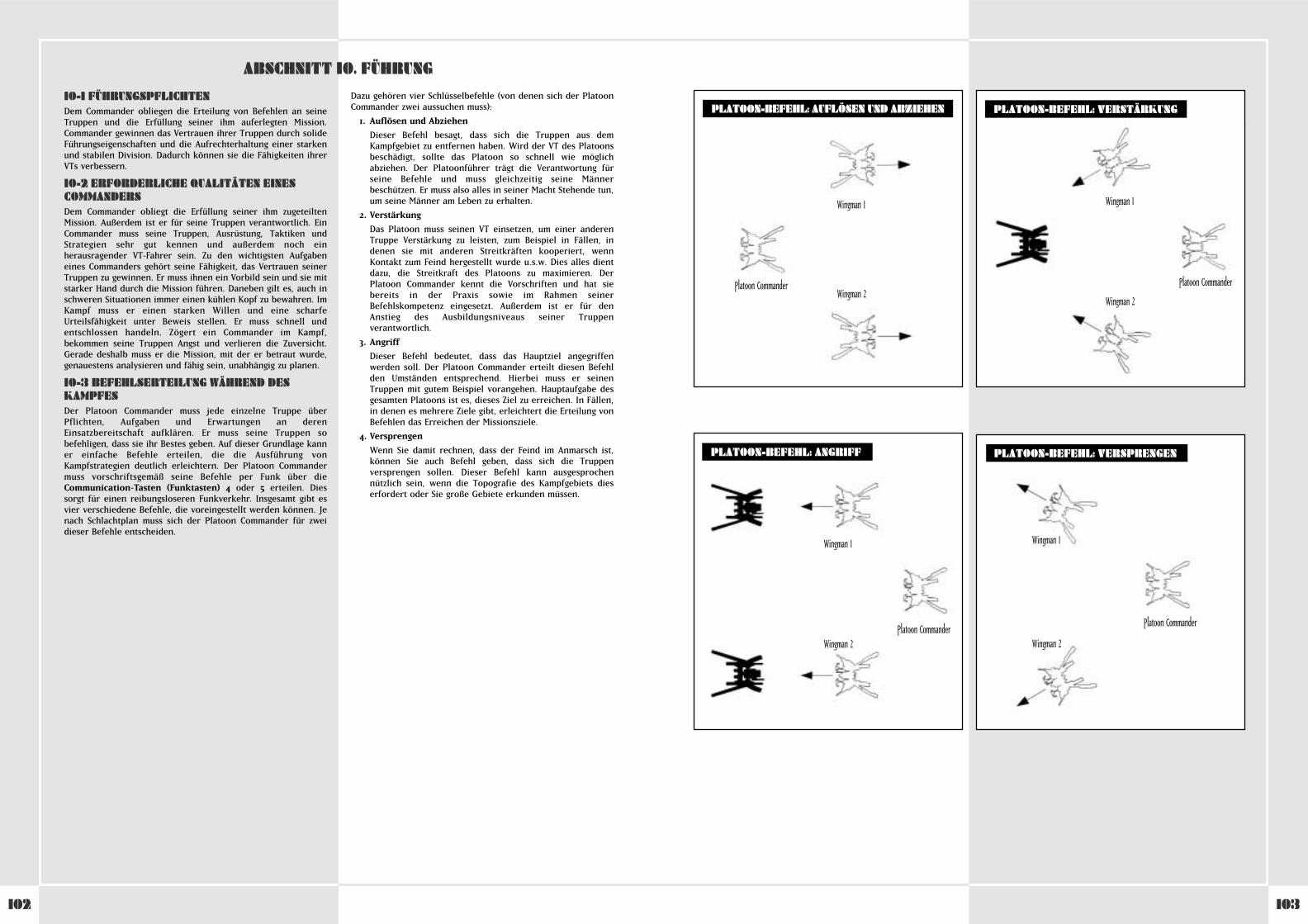
103102
10-1 FÜHRUNGSPFLICHTENDem Commander obliegen die Erteilung von Befehlen an seineTruppen und die Erfüllung seiner ihm auferlegten Mission.Commander gewinnen das Vertrauen ihrer Truppen durch solideFührungseigenschaften und die Aufrechterhaltung einer starkenund stabilen Division. Dadurch können sie die Fähigkeiten ihrerVTs verbessern.
10-2 ERFORDERLICHE QUALITÄTEN EINESCOMMANDERSDem Commander obliegt die Erfüllung seiner ihm zugeteiltenMission. Außerdem ist er für seine Truppen verantwortlich. EinCommander muss seine Truppen, Ausrüstung, Taktiken undStrategien sehr gut kennen und außerdem noch einherausragender VT-Fahrer sein. Zu den wichtigsten Aufgabeneines Commanders gehört seine Fähigkeit, das Vertrauen seinerTruppen zu gewinnen. Er muss ihnen ein Vorbild sein und sie mitstarker Hand durch die Mission führen. Daneben gilt es, auch inschweren Situationen immer einen kühlen Kopf zu bewahren. ImKampf muss er einen starken Willen und eine scharfeUrteilsfähigkeit unter Beweis stellen. Er muss schnell undentschlossen handeln. Zögert ein Commander im Kampf,bekommen seine Truppen Angst und verlieren die Zuversicht.Gerade deshalb muss er die Mission, mit der er betraut wurde,genauestens analysieren und fähig sein, unabhängig zu planen.
10-3 BEFEHLSERTEILUNG WÄHREND DESKAMPFESDer Platoon Commander muss jede einzelne Truppe überPflichten, Aufgaben und Erwartungen an derenEinsatzbereitschaft aufklären. Er muss seine Truppen sobefehligen, dass sie ihr Bestes geben. Auf dieser Grundlage kanner einfache Befehle erteilen, die die Ausführung vonKampfstrategien deutlich erleichtern. Der Platoon Commandermuss vorschriftsgemäß seine Befehle per Funk über dieCommunication-Tasten (Funktasten) 4 oder 5 erteilen. Diessorgt für einen reibungsloseren Funkverkehr. Insgesamt gibt esvier verschiedene Befehle, die voreingestellt werden können. Jenach Schlachtplan muss sich der Platoon Commander für zweidieser Befehle entscheiden.
Dazu gehören vier Schlüsselbefehle (von denen sich der PlatoonCommander zwei aussuchen muss):
1. Auflösen und Abziehen
Dieser Befehl besagt, dass sich die Truppen aus demKampfgebiet zu entfernen haben. Wird der VT des Platoonsbeschädigt, sollte das Platoon so schnell wie möglichabziehen. Der Platoonführer trägt die Verantwortung fürseine Befehle und muss gleichzeitig seine Männerbeschützen. Er muss also alles in seiner Macht Stehende tun,um seine Männer am Leben zu erhalten.
2. Verstärkung
Das Platoon muss seinen VT einsetzen, um einer anderenTruppe Verstärkung zu leisten, zum Beispiel in Fällen, indenen sie mit anderen Streitkräften kooperiert, wennKontakt zum Feind hergestellt wurde u.s.w. Dies alles dientdazu, die Streitkraft des Platoons zu maximieren. DerPlatoon Commander kennt die Vorschriften und hat siebereits in der Praxis sowie im Rahmen seinerBefehlskompetenz eingesetzt. Außerdem ist er für denAnstieg des Ausbildungsniveaus seiner Truppenverantwortlich.
3. Angriff
Dieser Befehl bedeutet, dass das Hauptziel angegriffenwerden soll. Der Platoon Commander erteilt diesen Befehlden Umständen entsprechend. Hierbei muss er seinenTruppen mit gutem Beispiel vorangehen. Hauptaufgabe desgesamten Platoons ist es, dieses Ziel zu erreichen. In Fällen,in denen es mehrere Ziele gibt, erleichtert die Erteilung vonBefehlen das Erreichen der Missionsziele.
4. Versprengen
Wenn Sie damit rechnen, dass der Feind im Anmarsch ist,können Sie auch Befehl geben, dass sich die Truppenversprengen sollen. Dieser Befehl kann ausgesprochennützlich sein, wenn die Topografie des Kampfgebiets dieserfordert oder Sie große Gebiete erkunden müssen.
WHEN USING THE PLASMA TORCH
ABSCHNITT 10. FÜHRUNG
PLATOON-BEFEHL: AUFLÖSEN UND ABZIEHEN PLATOON-BEFEHL: VERSTÄRKUNG
PLATOON-BEFEHL: ANGRIFF PLATOON-BEFEHL: VERSPRENGEN
Wingman 1
Wingman 2Platoon Commander
Wingman 1
Wingman 2
Platoon Commander
Wingman 1
Wingman 2Platoon Commander
Wingman 1
Wingman 2
Platoon Commander

105104
WHEN USING THE PLASMA TORCH
TECHNISCHER ANHANG
COCKPIT: 1. GENERATION
Vordere Hinderniswarnleuchte
Mehrfachmonitor
Unterwaffe 1 Bezeichnung
Unterwaffe 1 verbleibende Einsätze
Hauptwaffe 1 BezeichnungHauptwaffe 1 verbleibende MagazineHauptwaffe 1 verbleibende Munition
Interne Feuerwarnleuchte
Rechte Hinderniswarnleuchte
Linke Hinderniswarnleuchte
Hauptwaffe 2 BezeichnungHauptwaffe 2 verbleibende MagazineHauptwaffe 2 verbleibende MunitionHauptwaffe 3 BezeichnungHauptwaffe 3 verbleibende MagazineHauptwaffe 3 verbleibende Munition
Funkleuchten 1–5
Batteriemesser
Motordrehzahlmesser
Geschwindigkeitsmesser
HauptenergiemesserSchadensleuchte
Sub-MonitorSchaltleuchteDigitaler
GeschwindigkeitsmesserDeaktivierung
Stabilisatorbegrenzung
Tuner
Unterwaffe 2 Bezeichnung
Unterwaffe 2 verbleibende Einsätze
Subenergie-Tankmesser 1Nebentank 1angebracht oder
nicht Nebentank 1 im EinsatzSubenergie-Tankmesser 2
Nebentank 2angebracht oder
nichtNebentank 2 im Einsatz
Unterwaffe 3 Bezeichnung
Unterwaffe 3 verbleibende Einsätze
Düppel verbleibende Einsätze
WHEN USING THE PLASMA TORCHCOCKPIT: 2. GENERATION
Vordere Hinderniswarnleuchte
Deaktivierung Stabilisatorbegrenzung
Mehrfachmonitor
Hauptwaffe Bezeichnung
Hauptwaffe 1 verbleibende MagazineHauptwaffe 1 verbleibende Munition
Interne Feuerwarnleuchte Interne Feuerwarnleuchte
Rechte HinderniswarnleuchteLinke Hinderniswarnleuchte
Funkleuchten 1-5
BatteriemesserOverdrive-Leuchte
Motordrehzahlmesser
Geschwindigkeitsmesser
Hauptenergiemesser
SchadensanzeigerSub-MonitorSchaltanzeiger
Digitaler Geschwindigkeitsmesser
Tuner
Unterwaffe 1 Bezeichnung
Unterwaffe 1 verbleibende Einsätze
Subenergie-Tankmesser
Nebentank 1 im EinsatzNebentank 1Verfügbarkeit
Nebentank 2 imEinsatz
Nebentank 2Verfügbarkeit
Düppel verbleibende Einsätze
HAUPTMONITORDARSTELLUNG: 2. GENERATION
TIME . . . . . . . . . . . . . . . . . . . . . . . . . . . . . Verbleibende ZeitFSS . . . . . . . . . . . . . . . . . . . . . . . . . . . . . . . Zeigt die Betriebsbereitschaft Ihres FSS-Systems anSUB . . . . . . . . . . . . . . . . . . . . . . . . . . . . . . Unterwaffen-Info . . . . . . . . . . . . . . . . . . . . . . . . . . . . . . . . . RELOAD – Sie sind mitten im Nachladevorgang . . . . . . . . . . . . . . . . . . . . . . . . . . . . . . . . . HIT/MISS – Ihre Unterwaffe hat das Ziel getroffen oder verfehlt
SUPPLY INFO . . . . . . . . . . . . . . . . . . . . . . . . STAND BY – Nachschub wird vorbereitet . . . . . . . . . . . . . . . . . . . . . . . . . . . . . . . . . REFUEL – Auftankvorgang aktiv . . . . . . . . . . . . . . . . . . . . . . . . . . . . . . . . . COMPLETE – Der Auftankvorgang wurde beendet
DESTROYED . . . . . . . . . . . . . . . . . . . . . . . . . Ein Feind wurde vernichtetMISSION COMPLETE . . . . . . . . . . . . . . . . . . . Zeigt an, in welchem Umfang die Mission abgeschlossen wurdeMAIN . . . . . . . . . . . . . . . . . . . . . . . . . . . . . Hauptwaffen-Info . . . . . . . . . . . . . . . . . . . . . . . . . . . . . . . . . RELOAD – Sie sind mitten im Nachladevorgang . . . . . . . . . . . . . . . . . . . . . . . . . . . . . . . . . HIT/MISS – Ihre Hauptwaffe hat das Ziel getroffen oder verfehlt
WARN . . . . . . . . . . . . . . . . . . . . . . . . . . . . . Warnt Sie davor, dass der Feind Ihren VT ins Visier genommen hatSHOT . . . . . . . . . . . . . . . . . . . . . . . . . . . . . Zeigt an, dass der Feind eine nicht gelenkte Waffe auf Sie abgefeuert hatBOMB . . . . . . . . . . . . . . . . . . . . . . . . . . . . . Warnt Sie davor, dass Bomben mit gekrümmter Geschossbahn im Anflug sindMSSL . . . . . . . . . . . . . . . . . . . . . . . . . . . . . Warnt Sie davor, dass eine Lenkrakete im Anflug istNML . . . . . . . . . . . . . . . . . . . . . . . . . . . . . . Zeigt den Normalbetrieb an (Overdrive deaktiviert)OVRD . . . . . . . . . . . . . . . . . . . . . . . . . . . . . Zeigt an, dass Sie sich im Overdrive-Modus befindenHEAT . . . . . . . . . . . . . . . . . . . . . . . . . . . . . Zeigt an, dass sich die Batterie überhitzt hatBLNC . . . . . . . . . . . . . . . . . . . . . . . . . . . . . Zeigt an, dass der Stabilisator langsam seinen kritischen Punkt erreichtAREA . . . . . . . . . . . . . . . . . . . . . . . . . . . . . Zeigt an, dass Sie gerade das gekennzeichnete Kampfgebiet verlassenx 1.00 . . . . . . . . . . . . . . . . . . . . . . . . . . . . . Hauptkamera-VergrößerungsverhältnisANGLE OF DEPRESSION/ELEVATION (TIEFENWINKEL/HÖHENWINKEL) . . . . . . . . . . . Zeigt den Kamerawinkel anCOMPASS . . . . . . . . . . . . . . . . . . . . . . . . . . Zeigt die Richtung an, in die Sie sich bewegen.
HAUPTMONITORDARSTELLUNG: 1. GENERATION
ZEIT . . . . . . . . . . . . . . . . . . . . . . . . . . . . . . Verbleibende ZeitFSS . . . . . . . . . . . . . . . . . . . . . . . . . . . . . . . Zeigt die Betriebsbereitschaft Ihres FSS-Systems anSUB . . . . . . . . . . . . . . . . . . . . . . . . . . . . . . Unterwaffen-Info . . . . . . . . . . . . . . . . . . . . . . . . . . . . . . . . . RELOAD – Sie sind mitten im Nachladevorgang . . . . . . . . . . . . . . . . . . . . . . . . . . . . . . . . . HIT/MISS – Ihre Unterwaffe hat das Ziel getroffen oder verfehlt
SUPPLY INFO (NACHSCHUBINFO) . . . . . . . . . . . STAND BY – Nachschub wird vorbereitet . . . . . . . . . . . . . . . . . . . . . . . . . . . . . . . . . REFUEL – Auftankvorgang aktiv . . . . . . . . . . . . . . . . . . . . . . . . . . . . . . . . . COMPLETE – Der Auftankvorgang ist abgeschlossen
DESTROYED . . . . . . . . . . . . . . . . . . . . . . . . . Ein Feind wurde vernichtetMISSION COMPLETE (MISSION BEENDET . . . . . . Zeigt an, in welchem Umfang die Mission abgeschlossen wurdeMAIN . . . . . . . . . . . . . . . . . . . . . . . . . . . . . Hauptwaffen-Info . . . . . . . . . . . . . . . . . . . . . . . . . . . . . . . . . RELOAD – Sie sind mitten im Nachladevorgang . . . . . . . . . . . . . . . . . . . . . . . . . . . . . . . . . HIT/MISS – Ihre Hauptwaffe hat das Ziel getroffen oder verfehlt
WARN . . . . . . . . . . . . . . . . . . . . . . . . . . . . . Warnt Sie davor, dass der Feind Ihren VT im Visier hatSHOT . . . . . . . . . . . . . . . . . . . . . . . . . . . . . Zeigt an, dass der Feind eine nicht gelenkte Waffe auf Sie abgefeuert hatBOMB . . . . . . . . . . . . . . . . . . . . . . . . . . . . . Warnt Sie davor, dass Bomben mit gekrümmter Geschossflugbahn im Anflug sindMSSL . . . . . . . . . . . . . . . . . . . . . . . . . . . . . Warnt Sie davor, dass eine Lenkrakete im Anflug istNML . . . . . . . . . . . . . . . . . . . . . . . . . . . . . . Zeigt den Normalbetrieb an (Overdrive deaktiviert)OVRD . . . . . . . . . . . . . . . . . . . . . . . . . . . . . Zeigt an, dass Sie sich im Overdrive-Modus befindenHEAT . . . . . . . . . . . . . . . . . . . . . . . . . . . . . Zeigt an, dass sich die Batterie überhitzt hatBLNC . . . . . . . . . . . . . . . . . . . . . . . . . . . . . Zeigt an, dass der Stabilisator langsam seinen kritischen Punkt erreichtAREA . . . . . . . . . . . . . . . . . . . . . . . . . . . . . Zeigt an, dass Sie gerade das gekennzeichnete Kampfgebiet verlassen4.63 . . . . . . . . . . . . . . . . . . . . . . . . . . . . . . Hauptkamera-VergrößerungsverhältnisANGLE OF DEPRESSION/ELEVATION (TIEFENWINKEL/HÖHENWINKEL) . . . . . . . . . . . Zeigt den Kamerawinkel anCOMPASS . . . . . . . . . . . . . . . . . . . . . . . . . . Zeigt die Richtung an, in die Sie sich bewegen.
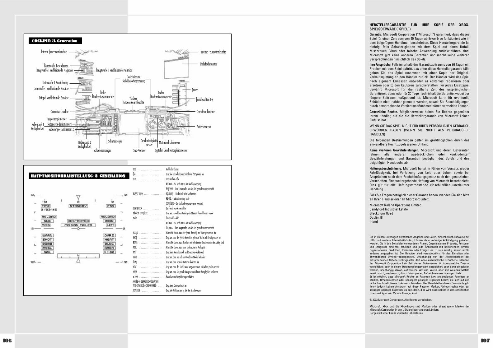
107106
HERSTELLERGARANTIE FÜR IHRE KOPIE DER XBOX-SPIELSOFTWARE (“SPIEL”)Garantie. Microsoft Corporation (“Microsoft”) garantiert, dass diesesSpiel für einen Zeitraum von 90 Tagen ab Erwerb so funktioniert wie indem beigefügten Handbuch beschrieben. Diese Herstellergarantie istnichtig, falls Schwierigkeiten mit dem Spiel auf einen Unfall,Missbrauch, Virus oder falsche Anwendung zurückzuführen sind.Microsoft gibt keine anderen Garantien und macht keine weiterenVersprechungen hinsichtlich des Spiels.Ihre Ansprüche. Falls innerhalb des Garantiezeitraums von 90 Tagen einProblem mit dem Spiel auftritt, das unter diese Herstellergarantie fällt,geben Sie das Spiel zusammen mit einer Kopie der Original-Verkaufsquittung an den Händler zurück. Der Händler wird das Spielnach eigenem Ermessen entweder a) kostenlos reparieren oderersetzen oder b) den Kaufpreis zurückerstatten. Für jedes Ersatzspielgewährt Microsoft für die restliche Zeit des ursprünglichenGarantiezeitraums oder für 30 Tage nach Erhalt die Garantie, wobei derlängere Zeitraum maßgebend ist. Microsoft kann für eventuelleSchäden nicht haftbar gemacht werden, soweit Sie Beschädigungendurch entsprechende Vorsichtsmaßnahmen hätten vermeiden können.
Gesetzliche Rechte. Möglicherweise haben Sie Rechte gegenüberIhrem Händler, auf die die Herstellergarantie von Microsoft keinenEinfluss hat.
WENN SIE DAS SPIEL NICHT FÜR IHREN PERSÖNLICHEN GEBRAUCHERWORBEN HABEN (WENN SIE NICHT ALS VERBRAUCHERHANDELN)
Die folgenden Bestimmungen gelten im größtmöglichen durch dasanwendbare Recht zugelassenen Umfang.
Keine weiteren Gewährleistungen. Microsoft und deren Lieferantenlehnen alle anderen ausdrücklichen oder konkludentenGewährleistungen und Garantien bezüglich des Spiels und desbeigefügten Handbuchs ab.
Haftungsbeschränkung. Microsoft haftet in Fällen von Vorsatz, groberFahrlässigkeit, bei Verletzung von Leib oder Leben sowie beiAnsprüchen nach dem Produkthaftungsgesetz nach den gesetzlichenVorschriften. Eine weitergehende Haftung von Microsoft besteht nicht.Dies gilt für alle Haftungstatbestände einschließlich unerlaubterHandlung.
Falls Sie Fragen bezüglich dieser Garantie haben, wenden Sie sich bittean Ihren Händler oder an Microsoft unter:
Microsoft Ireland Operations LimitedSandyford Industrial EstateBlackthorn RoadDublin 18Irland
Die in diesen Unterlagen enthaltenen Angaben und Daten, einschließlich Hinweise aufURLs und weitere Internet-Websites, können ohne vorherige Ankündigung geändertwerden. Die in den Beispielen verwendeten Firmen, Organisationen, Produkte, Personenund Ereignisse sind frei erfunden und jede Ähnlichkeit mit bestehenden Firmen,Organisationen, Produkten, Personen oder Ereignissen ist rein zufällig, soweit nichtsanderes angegeben ist. Die Benutzer sind verantwortlich für das Einhalten alleranwendbaren Urheberrechtsgesetze. Unabhängig von der Anwendbarkeit derentsprechenden Urheberrechtsgesetze darf ohne ausdrückliche schriftliche Erlaubnisder Microsoft Corporation kein Teil dieses Dokumentes für irgendwelche Zweckevervielfältigt oder in einem Datenempfangssystem gespeichert oder darin eingelesenwerden, unabhängig davon, auf welche Art und Weise oder mit welchen Mitteln(elektronisch, mechanisch, durch Fotokopieren, Aufzeichnen usw.) dies geschieht. Es ist möglich, dass Microsoft Rechte an Patenten bzw. angemeldeten Patenten, anMarken, Urheberrechten oder sonstigem geistigen Eigentum besitzt, die sich auf denfachlichen Inhalt dieses Dokuments beziehen. Das Bereitstellen dieses Dokuments gibtIhnen jedoch keinen Anspruch auf diese Patente, Marken, Urheberrechte oder aufsonstiges geistiges Eigentum, es sein denn, dies wird ausdrücklich in den schriftlichenLizenzverträgen von Microsoft eingeräumt.
© 2003 Microsoft Corporation. Alle Rechte vorbehalten.
Microsoft, Xbox und die Xbox-Logos sind Marken oder eingetragene Marken derMicrosoft Corporation in den USA und/oder anderen Ländern. Hergestellt unter Lizenz von Dolby Laboratories.
WHEN USING THE PLASMA TORCHCOCKPIT: 3. Generation
VordereHinderniswarnleuchte
DeaktivierungStabilisatorbegrenzung
MehrfachmonitorHauptwaffe BezeichnungHauptwaffe 1 verbleibende Magazine Hauptwaffe 1 verbleibende Munition
Interne Feuerwarnleuchte Interne Feuerwarnleuchte
RechteHinderniswarnleuchte
LinkeHinderniswarnleuchte
Funkleuchten 1-5
Batteriemesser
Overdrive-LeuchteOverdrive-Leuchte
MotordrehzahlmesserGeschwindigkeitsmesser
Hauptenergiemesser
Schadensanzeiger Sub-Monitor
Schaltanzeiger
Digitaler Geschwindigkeitsmesser
Tuner
Unterwaffe 1 BezeichnungUnterwaffe 1 verbleibende Einsätze
Subenergie-Tankmesser 1Nebentank 1Verfügbarkeit Subenergie-Tankmesser 2
Nebentank 2Verfügbarkeit
Düppel verbleibende Einsätze
HAUPTMONITORDARSTELLUNG: 3. GENERATION
ZEIT . . . . . . . . . . . . . . . . . . . . . . . . . . Verbleibende ZeitFSS . . . . . . . . . . . . . . . . . . . . . . . . . . . Zeigt die Betriebsbereitschaft Ihres FSS-Systems anSUB . . . . . . . . . . . . . . . . . . . . . . . . . . Unterwaffen-Info . . . . . . . . . . . . . . . . . . . . . . . . . . . . . RELOAD – Sie sind mitten im Nachladevorgang . . . . . . . . . . . . . . . . . . . . . . . . . . . . . HAT/MISS – Ihre Unterwaffe hat das Ziel getroffen oder verfehlt
SUPPLY INFO . . . . . . . . . . . . . . . . . . . . STAND BY – Nachschub wird vorbereitet . . . . . . . . . . . . . . . . . . . . . . . . . . . . . REFUEL – Auftankvorgang aktiv . . . . . . . . . . . . . . . . . . . . . . . . . . . . . COMPLETE – Der Auftankvorgang wurde beendet
DESTROYED . . . . . . . . . . . . . . . . . . . . . Ein Feind wurde vernichtetMISSION COMPLETE . . . . . . . . . . . . . . . Zeigt an, in welchem Umfang die Mission abgeschlossen wurdeMAIN . . . . . . . . . . . . . . . . . . . . . . . . . Hauptwaffen-Info . . . . . . . . . . . . . . . . . . . . . . . . . . . . . RELOAD – Sie sind mitten im Nachladevorgang . . . . . . . . . . . . . . . . . . . . . . . . . . . . . HIT/MISS – Ihre Hauptwaffe hat das Ziel getroffen oder verfehlt
WARN . . . . . . . . . . . . . . . . . . . . . . . . . Warnt Sie davor, dass der Feind Ihren VT ins Visier genommen hatSHOT . . . . . . . . . . . . . . . . . . . . . . . . . Zeigt an, dass der Feind eine nicht gelenkte Waffe auf Sie abgefeuert hatBOMB . . . . . . . . . . . . . . . . . . . . . . . . . Warnt Sie davor, dass Bomben mit gekrümmter Geschossbahn im Anflug sindMSSL . . . . . . . . . . . . . . . . . . . . . . . . . Warnt Sie davor, dass eine Lenkrakete im Anflug istNML . . . . . . . . . . . . . . . . . . . . . . . . . . Zeigt den Normalbetrieb an (Overdrive deaktiviert)OVRD . . . . . . . . . . . . . . . . . . . . . . . . . Zeigt an, dass Sie sich im Overdrive-Modus befindenHEAT . . . . . . . . . . . . . . . . . . . . . . . . . Zeigt an, dass sich die Batterie überhitzt hatBLNC . . . . . . . . . . . . . . . . . . . . . . . . . Zeigt an, dass der Stabilisator langsam seinen kritischen Punkt erreichtAREA . . . . . . . . . . . . . . . . . . . . . . . . . Zeigt an, dass Sie gerade das gekennzeichnete Kampfgebiet verlassenx 1.00 . . . . . . . . . . . . . . . . . . . . . . . . . Hauptkamera-VergrößerungsverhältnisANGLE OF DEPRESSION/ELEVATION (TIEFENWINKEL/HÖHENWINKEL) . . . . . . . Zeigt den Kamerawinkel anCOMPASS . . . . . . . . . . . . . . . . . . . . . . Zeigt die Richtung an, in die Sie sich bewegen.
109108
INSTALACIÓN DEL CONTROLADOR . . . . . . . . . . . . . . . . . . . . . . . . . . . . . . . . . . . . . . . 110
Precauciones . . . . . . . . . . . . . . . . . . . . . . . . . . . . . . . . . . . . . . . . . . . . . . . . . . 110
Solución de problemas . . . . . . . . . . . . . . . . . . . . . . . . . . . . . . . . . . . . . . . . . . . 110
Montaje de la unidad derecha . . . . . . . . . . . . . . . . . . . . . . . . . . . . . . . . . . . . . 110
Montaje de la unidad izquierda . . . . . . . . . . . . . . . . . . . . . . . . . . . . . . . . . . . . 110
SECCIÓN 1. CONCEPTO DE VT Y DIVISIÓN PANZER ESPECIAL . . . . . . . . . . . . . . . . . . . . 112
1-1 Concepto de VT . . . . . . . . . . . . . . . . . . . . . . . . . . . . . . . . . . . . . . . . . . . . . . 112
1-2 Fundamentos del VT de uso militar . . . . . . . . . . . . . . . . . . . . . . . . . . . . . . . 112
1-3 Deberes de la Unidad Acorazada Especial . . . . . . . . . . . . . . . . . . . . . . . . . . 112
1-4 Formación de la División Panzer Especial . . . . . . . . . . . . . . . . . . . . . . . . . . 112
1-5 Operación del Pelotón de VT . . . . . . . . . . . . . . . . . . . . . . . . . . . . . . . . . . . 112
SECCIÓN 2. RESÚMEN DEL VT . . . . . . . . . . . . . . . . . . . . . . . . . . . . . . . . . . . . . . . . . . . . 113
2-1 Piezas básicas del VT . . . . . . . . . . . . . . . . . . . . . . . . . . . . . . . . . . . . . . . . . . 113
2-2 Sistema de control del VT . . . . . . . . . . . . . . . . . . . . . . . . . . . . . . . . . . . . . . 113
2-3 Tipos de VT . . . . . . . . . . . . . . . . . . . . . . . . . . . . . . . . . . . . . . . . . . . . . . . . . 114
2-4 Movimiento . . . . . . . . . . . . . . . . . . . . . . . . . . . . . . . . . . . . . . . . . . . . . . . . . 114
2-5 Depósito de combustible y depósitos de reserva . . . . . . . . . . . . . . . . . . . . 114
2-6 Consumo de combustible y tiempo de movimiento estimado . . . . . . . . . . 114
2-7 Blindaje defensivo . . . . . . . . . . . . . . . . . . . . . . . . . . . . . . . . . . . . . . . . . . . 114
2-8 Arma principal y arma secundaria . . . . . . . . . . . . . . . . . . . . . . . . . . . . . . . 114
2-9 Margen de peso máximo del armamento . . . . . . . . . . . . . . . . . . . . . . . . . . 114
2-10 Armamento cargado en el VT . . . . . . . . . . . . . . . . . . . . . . . . . . . . . . . . . . 115
2-11 Alcance de tiro del armamento con trayectoria curva
en el mapa de guerra . . . . . . . . . . . . . . . . . . . . . . . . . . . . . . . . . . . . . . . . . . . .120
2-12 Espoleta corta . . . . . . . . . . . . . . . . . . . . . . . . . . . . . . . . . . . . . . . . . . . . . . 120
2-13 Defensa antirradar . . . . . . . . . . . . . . . . . . . . . . . . . . . . . . . . . . . . . . . . . . 120
SECCIÓN 3a. FUNCIONES ESPECIALES
HASTA LA 2aª GENERACIÓN DEL COOS . . . . . . . . . . . . . . . . . . . . . . . . . . . . . . . . . . . . . 120
3-1 Adiciones al coos de 2ªa generación . . . . . . . . . . . . . . . . . . . . . . . . . . . . . . 120
3-2 Función FSS (Sistema de disparo por estimación del objetivo) . . . . . . . . . 120
3-3 Función Overdrive (Superdirecta) . . . . . . . . . . . . . . . . . . . . . . . . . . . . . . . . 120
3-4 Función Stealth (Sigilo) . . . . . . . . . . . . . . . . . . . . . . . . . . . . . . . . . . . . . . . . 120
3-5 Armas guiadas . . . . . . . . . . . . . . . . . . . . . . . . . . . . . . . . . . . . . . . . . . . . . . 120
SECCIÓN 4. CONTROLES DEL VT . . . . . . . . . . . . . . . . . . . . . . . . . . . . . . . . . . . . . . . . . . 121
4-1 Secuencia de inicio . . . . . . . . . . . . . . . . . . . . . . . . . . . . . . . . . . . . . . . . . . . 121
4-2 Cuando se para el VT durante el inicio . . . . . . . . . . . . . . . . . . . . . . . . . . . . 121
Controles básicos . . . . . . . . . . . . . . . . . . . . . . . . . . . . . . . . . . . . . . . . . . . . . . . 122
4-3 Moverse y detenerse . . . . . . . . . . . . . . . . . . . . . . . . . . . . . . . . . . . . . . . . . 122
4-4 Aceleración y desaceleración . . . . . . . . . . . . . . . . . . . . . . . . . . . . . . . . . . . 122
4-5 Rotación . . . . . . . . . . . . . . . . . . . . . . . . . . . . . . . . . . . . . . . . . . . . . . . . . . . 122
4-6 Overdrive (Superdirecta) . . . . . . . . . . . . . . . . . . . . . . . . . . . . . . . . . . . . . . . 122
4-7 Función Slidestep (Deslizamiento) . . . . . . . . . . . . . . . . . . . . . . . . . . . . . . . 122
4-8 Limitaciones funcionales del deslizamiento . . . . . . . . . . . . . . . . . . . . . . . . 122
4-9 Regulador de inclinación de deslizamiento . . . . . . . . . . . . . . . . . . . . . . . . 122
4-10 Función Cut-off (Desconexión) . . . . . . . . . . . . . . . . . . . . . . . . . . . . . . . . . 122
4-11 Controles del manipulador . . . . . . . . . . . . . . . . . . . . . . . . . . . . . . . . . . . . 123
Pantalla del VT . . . . . . . . . . . . . . . . . . . . . . . . . . . . . . . . . . . . . . . . . . . . . . . . . 124
4-12 Cambio de la cámara principal . . . . . . . . . . . . . . . . . . . . . . . . . . . . . . . . . 124
4-13 Polvo y suciedad en la cámara principal . . . . . . . . . . . . . . . . . . . . . . . . . . 124
4-14 Funciones de la pantalla secundaria . . . . . . . . . . . . . . . . . . . . . . . . . . . . . 125
4-15 Equipo de visión nocturna . . . . . . . . . . . . . . . . . . . . . . . . . . . . . . . . . . . . 125
JCS (Sistema de mando completo) . . . . . . . . . . . . . . . . . . . . . . . . . . . . . . . . . . 125
4-16 Resumen de JCS . . . . . . . . . . . . . . . . . . . . . . . . . . . . . . . . . . . . . . . . . . . . . 125
4-17 Pantalla múltiple . . . . . . . . . . . . . . . . . . . . . . . . . . . . . . . . . . . . . . . . . . . . 126
4-18 Información mostrada en la pantalla múltiple . . . . . . . . . . . . . . . . . . . . . 126
Procedimientos de emergencia . . . . . . . . . . . . . . . . . . . . . . . . . . . . . . . . . . . . . . . . . 127
4-19 Configuración de la evacuación . . . . . . . . . . . . . . . . . . . . . . . . . . . . . . . . 127
4-20 Interruptor del eyector de emergencia . . . . . . . . . . . . . . . . . . . . . . . . . . 127
4-21 Procedimientos de escape de emergencia en ríos o mares . . . . . . . . . . . 127
4-22 Incendio en el casco . . . . . . . . . . . . . . . . . . . . . . . . . . . . . . . . . . . . . . . . . 127
SECCIÓN 5. ATAQUE DEL VT . . . . . . . . . . . . . . . . . . . . . . . . . . . . . . . . . . . . . . . . . . . . 128
5-1 Apuntar y disparar con armas . . . . . . . . . . . . . . . . . . . . . . . . . . . . . . . . . . 128
5-2 Función Lock-On (Bloqueo de objetivo) . . . . . . . . . . . . . . . . . . . . . . . . . . . 128
5-3 Puntería en combate cercano . . . . . . . . . . . . . . . . . . . . . . . . . . . . . . . . . . 128
5-4 FSS (Sistema de disparo por estimación del objetivo) . . . . . . . . . . . . . . . . 129
5-5 Alcances de tiro de diferentes armas . . . . . . . . . . . . . . . . . . . . . . . . . . . . . 129
5-6 Notas acerca del disparo con alcance de tiro eficaz . . . . . . . . . . . . . . . . . 129
5-7 Utilizar un alcance de tiro eficaz . . . . . . . . . . . . . . . . . . . . . . . . . . . . . . . . 130
5-8 Ataque de tierra arrasada . . . . . . . . . . . . . . . . . . . . . . . . . . . . . . . . . . . . . 130
5-9 Cambio de arma . . . . . . . . . . . . . . . . . . . . . . . . . . . . . . . . . . . . . . . . . . . . 130
5-10 Recargar armas con cargador . . . . . . . . . . . . . . . . . . . . . . . . . . . . . . . . . . 130
SECCIÓN 6. MOVIMIENTO DEL VT . . . . . . . . . . . . . . . . . . . . . . . . . . . . . . . . . . . . . . . . 131
6-1 En general . . . . . . . . . . . . . . . . . . . . . . . . . . . . . . . . . . . . . . . . . . . . . . . . . . 131
6-2 Utilizar la meteorología y la topografía . . . . . . . . . . . . . . . . . . . . . . . . . . . 131
CONFIGURACIÓN DEL CONTROLADOR DE STEEL BATTALION . . . . . . . . . . . . . . . . . . . . 132
SECCIÓN 7. PREPARATIVOS DE LA ESTREGIA DEL PELOTÓN . . . . . . . . . . . . . . . . . . . . . 134
7-1 Órdenes . . . . . . . . . . . . . . . . . . . . . . . . . . . . . . . . . . . . . . . . . . . . . . . . . . . . 134
7-2 Análisis de la misión . . . . . . . . . . . . . . . . . . . . . . . . . . . . . . . . . . . . . . . . . . 134
7-3 Elección del armamento . . . . . . . . . . . . . . . . . . . . . . . . . . . . . . . . . . . . . . . 134
7-4 Selección de blindaje adicional y armamento secundario . . . . . . . . . . . . . 134
7-5 Elección del VT . . . . . . . . . . . . . . . . . . . . . . . . . . . . . . . . . . . . . . . . . . . . . . 134
7-6 Adjuntar depósitos de combustible y blindaje adicionales . . . . . . . . . . . . 134
7-7 Solicitudes de suministro . . . . . . . . . . . . . . . . . . . . . . . . . . . . . . . . . . . . . . 134
7-8 Provisiones de alimentos del VT . . . . . . . . . . . . . . . . . . . . . . . . . . . . . . . . 134
7-9 Llevar efectos personales a la cabina . . . . . . . . . . . . . . . . . . . . . . . . . . . . 134
SECCIÓN 8. TRANSMISIONES DE RADIO
8-1 Resumen . . . . . . . . . . . . . . . . . . . . . . . . . . . . . . . . . . . . . . . . . . . . . . . . . . . 135
8-2 Canales preestablecidos . . . . . . . . . . . . . . . . . . . . . . . . . . . . . . . . . . . . . . . 135
8-3 Procedimientos de la comunicación por radio . . . . . . . . . . . . . . . . . . . . . 135
8-4 Enviar un mensaje . . . . . . . . . . . . . . . . . . . . . . . . . . . . . . . . . . . . . . . . . . . 130
8-5 Recibir un mensaje . . . . . . . . . . . . . . . . . . . . . . . . . . . . . . . . . . . . . . . . . . 130
8-6 Repetir el mensaje . . . . . . . . . . . . . . . . . . . . . . . . . . . . . . . . . . . . . . . . . . 130
SECCIÓN 9. SUMINISTROS . . . . . . . . . . . . . . . . . . . . . . . . . . . . . . . . . . . . . . . . . . . . . . 137
9-1 Aceptar suministros . . . . . . . . . . . . . . . . . . . . . . . . . . . . . . . . . . . . . . . . . . 137
9-2 Clasificar suministros . . . . . . . . . . . . . . . . . . . . . . . . . . . . . . . . . . . . . . . . . 137
9-3 Suministro mediante helicóptero de suministros . . . . . . . . . . . . . . . . . . . . 137
9-4 Opciones y precauciones al recibir suministros . . . . . . . . . . . . . . . . . . . . . 137
9-5 Abrir el Centro de provisión de suministros . . . . . . . . . . . . . . . . . . . . . . . 137
SECCIÓN 10. LIDERAZGO . . . . . . . . . . . . . . . . . . . . . . . . . . . . . . . . . . . . . . . . . . . . . . . 138
10-1 Deberes del liderazgo . . . . . . . . . . . . . . . . . . . . . . . . . . . . . . . . . . . . . . . . 138
10-2 Cualidades necesarias para el mando . . . . . . . . . . . . . . . . . . . . . . . . . . . . 138
10-3 Órdenes durante la batalla . . . . . . . . . . . . . . . . . . . . . . . . . . . . . . . . . . . . 138
APÉNDICE TÉCNICO . . . . . . . . . . . . . . . . . . . . . . . . . . . . . . . . . . . . . . . . . . . . . . . . . . 140
Cabina: 1a Generación . . . . . . . . . . . . . . . . . . . . . . . . . . . . . . . . . . . . . . . . . . . 140
Pantalla principal: 1aª Generación . . . . . . . . . . . . . . . . . . . . . . . . . . . . . . . . . . 140
Cabina: 2ªa Generación . . . . . . . . . . . . . . . . . . . . . . . . . . . . . . . . . . . . . . . . . . . 141
Pantalla principal: 2aª Generación . . . . . . . . . . . . . . . . . . . . . . . . . . . . . . . . . . . 141
Cabina: 3ªa Generación . . . . . . . . . . . . . . . . . . . . . . . . . . . . . . . . . . . . . . . . . . . 142
Pantalla principal: 3aª Generación . . . . . . . . . . . . . . . . . . . . . . . . . . . . . . . . . . 142
Garantía . . . . . . . . . . . . . . . . . . . . . . . . . . . . . . . . . . . . . . . . . . . . . . . . . . . . . . 143
Atención al cliente . . . . . . . . . . . . . . . . . . . . . . . . . . . . . . . . . . . . . . . . . . . . . . 181
ESPAÑOLANTES DE UTILIZAR EL JUEGOGracias por comprar STEEL BATTALION. Lea los manuales deinstrucciones antes de empezar a jugar. Después de leer losmanuales, téngalos a mano en lugar seguro para que puedaconsultarlos rápida y fácilmente.
ADVERTENCIAS• Guarde la unidad y todos los componentes lejos del alcance
de los niños.
• No abra ni modifique la unidad ni los componentes.
• No derrame agua sobre la unidad o los componentes.
• Guarde la unidad y los componentes en un lugar seco ylibre de polvo.
• Si aparece algún problema, detenga el uso de inmediato.
ÍNDICE
INFORMACIÓN DE SEGURIDADInformación sobre los ataques epilépticosfotosensiblesUn porcentaje escaso de personas puede sufrir un ataquecuando se exponen a ciertas imágenes visuales, entre las que seincluyen las imágenes o las luces parpadeantes que aparecenen los videojuegos. Incluso aquellas personas que no tienen unhistorial de este tipo de ataques o epilepsia pueden serpropensos a estos “ataques epilépticos fotosensibles” cuandofijan la vista en un videojuego.
Estos ataques tienen varios síntomas: mareos, visión alterada,tics nerviosos en la cara o los ojos, temblores de brazos opiernas, desorientación, confusión o pérdida momentánea de laconciencia. Además, pueden ocasionar una pérdida delconocimiento o incluso convulsiones que conduzcan a unalesión propiciada por una caída o un golpe con algún objetocercano.
Si sufre cualquiera de estos síntomas, deje de jugarinmediatamente y consulte a un médico. Los padres debenobservar a sus hijos o preguntarles si han sufrido los síntomasantes mencionados; los niños y adolescentes tienen másposibilidades de sufrir estos ataques que los adultos.
Para reducir el riesgo de ataques epilépticos fotosensibles esaconsejable sentarse a una distancia considerable de lapantalla del televisor, utilizar una pantalla más pequeña, jugaren una habitación bien iluminada y no jugar cuando se estásomnoliento o cansado.
Si usted o algún familiar suyo posee un historial de ataquesepilépticos, consulte a su médico antes de jugar.
Información adicional importante sobre la salud y seguridadEl manual de instrucciones de la Xbox contiene informaciónimportante sobre la salud y seguridad que debería leer yasimilar antes de utilizar este software.
Evite daños en su televisorNo utilice este software en determinados televisores.Algunos aparatos, sobre todo los de proyección frontal oposterior, pueden sufrir daños si se utilizan para videojuegos,incluidos los juegos de la Xbox. Las imágenes estáticaspresentadas durante el desarrollo normal del juego pueden“quemar” la pantalla, lo que origina una sombra permanente deeste tipo de imágenes, incluso cuando no se está jugando. Sepueden producir daños similares debido a las imágenesestáticas que se crean al poner el videojuego en pausa.Consulte el manual de usuario del televisor para saber si sepueden utilizar videojuegos con total garantía y seguridad. Sino encuentra esta información en el manual, póngase encontacto con el distribuidor o el fabricante del televisor parasaber si se pueden utilizar videojuegos de forma segura en elaparato.
Queda totalmente prohibida la copia, ingeniería inversa,transmisión, reproducción pública, alquiler, partida a cambiode dinero o incumplimiento de la protección de copia sinautorización previa.
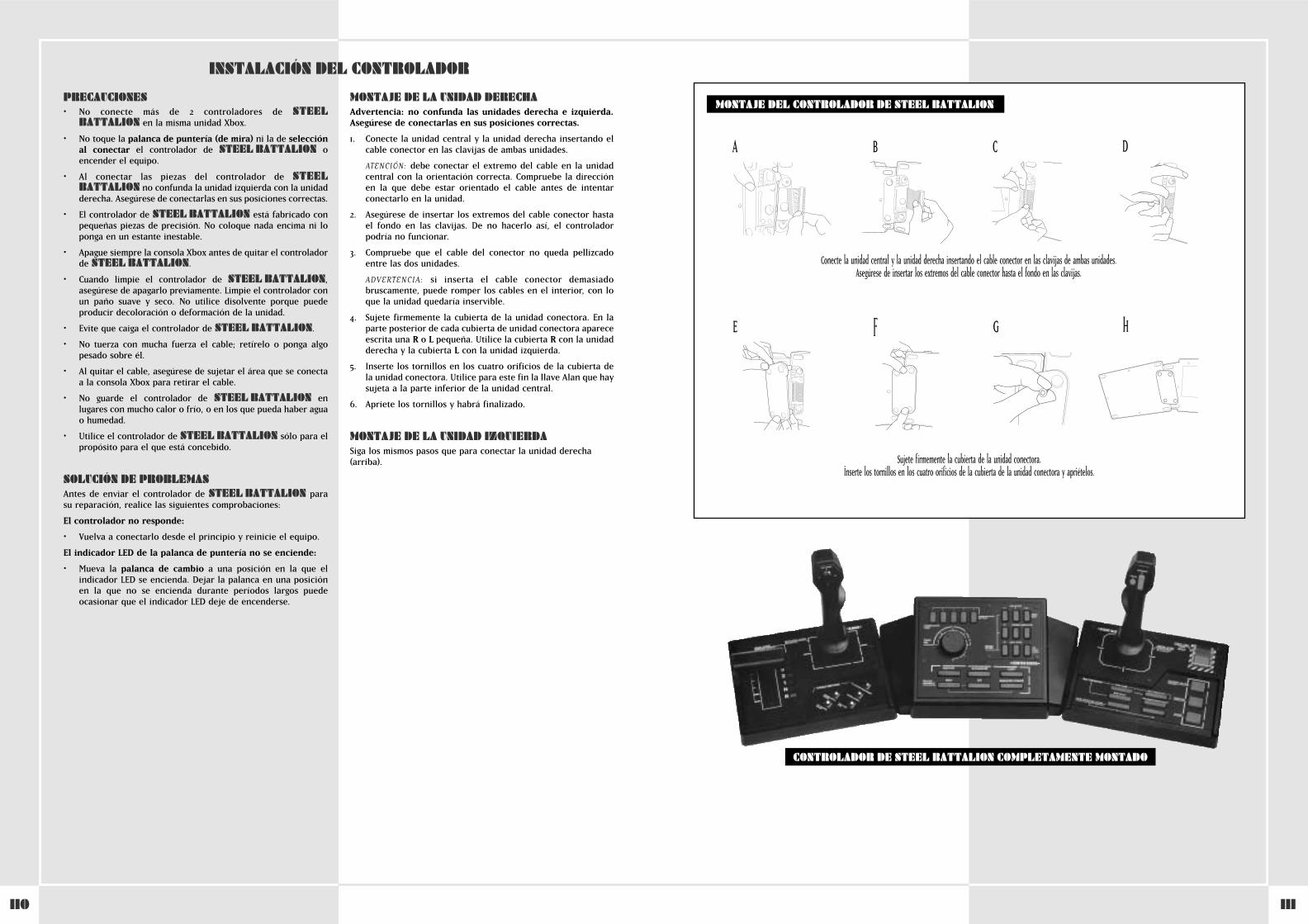
111110
INSTALACIÓN DEL CONTROLADOR
PRECAUCIONES• No conecte más de 2 controladores de STEEL
BATTALION en la misma unidad Xbox.
• No toque la palanca de puntería (de mira) ni la de selecciónal conectar el controlador de STEEL BATTALION oencender el equipo.
• Al conectar las piezas del controlador de STEELBATTALION no confunda la unidad izquierda con la unidadderecha. Asegúrese de conectarlas en sus posiciones correctas.
• El controlador de STEEL BATTALION está fabricado conpequeñas piezas de precisión. No coloque nada encima ni loponga en un estante inestable.
• Apague siempre la consola Xbox antes de quitar el controladorde STEEL BATTALION.
• Cuando limpie el controlador de STEEL BATTALION,asegúrese de apagarlo previamente. Limpie el controlador conun paño suave y seco. No utilice disolvente porque puedeproducir decoloración o deformación de la unidad.
• Evite que caiga el controlador de STEEL BATTALION.
• No tuerza con mucha fuerza el cable; retírelo o ponga algopesado sobre él.
• Al quitar el cable, asegúrese de sujetar el área que se conecta a la consola Xbox para retirar el cable.
• No guarde el controlador de STEEL BATTALION enlugares con mucho calor o frío, o en los que pueda haber agua o humedad.
• Utilice el controlador de STEEL BATTALION sólo para elpropósito para el que está concebido.
SOLUCIÓN DE PROBLEMASAntes de enviar el controlador de STEEL BATTALION parasu reparación, realice las siguientes comprobaciones:
El controlador no responde:
• Vuelva a conectarlo desde el principio y reinicie el equipo.
El indicador LED de la palanca de puntería no se enciende:
• Mueva la palanca de cambio a una posición en la que elindicador LED se encienda. Dejar la palanca en una posiciónen la que no se encienda durante períodos largos puedeocasionar que el indicador LED deje de encenderse.
MONTAJE DE LA UNIDAD DERECHAAdvertencia: no confunda las unidades derecha e izquierda.Asegúrese de conectarlas en sus posiciones correctas.
1. Conecte la unidad central y la unidad derecha insertando elcable conector en las clavijas de ambas unidades.
ATENCIÓN: debe conectar el extremo del cable en la unidadcentral con la orientación correcta. Compruebe la direcciónen la que debe estar orientado el cable antes de intentarconectarlo en la unidad.
2. Asegúrese de insertar los extremos del cable conector hastael fondo en las clavijas. De no hacerlo así, el controladorpodría no funcionar.
3. Compruebe que el cable del conector no queda pellizcadoentre las dos unidades.
ADVERTENCIA: si inserta el cable conector demasiadobruscamente, puede romper los cables en el interior, con loque la unidad quedaría inservible.
4. Sujete firmemente la cubierta de la unidad conectora. En laparte posterior de cada cubierta de unidad conectora apareceescrita una R o L pequeña. Utilice la cubierta R con la unidadderecha y la cubierta L con la unidad izquierda.
5. Inserte los tornillos en los cuatro orificios de la cubierta dela unidad conectora. Utilice para este fin la llave Alan que haysujeta a la parte inferior de la unidad central.
6. Apriete los tornillos y habrá finalizado.
MONTAJE DE LA UNIDAD IZQUIERDASiga los mismos pasos que para conectar la unidad derecha(arriba).
MONTAJE DEL CONTROLADOR DE STEEL BATTALION
CONTROLADOR DE STEEL BATTALION COMPLETAMENTE MONTADO
Conecte la unidad central y la unidad derecha insertando el cable conector en las clavijas de ambas unidades. Asegúrese de insertar los extremos del cable conector hasta el fondo en las clavijas.
Sujete firmemente la cubierta de la unidad conectora.Inserte los tornillos en los cuatro orificios de la cubierta de la unidad conectora y apriételos.
A B C D
E F G H
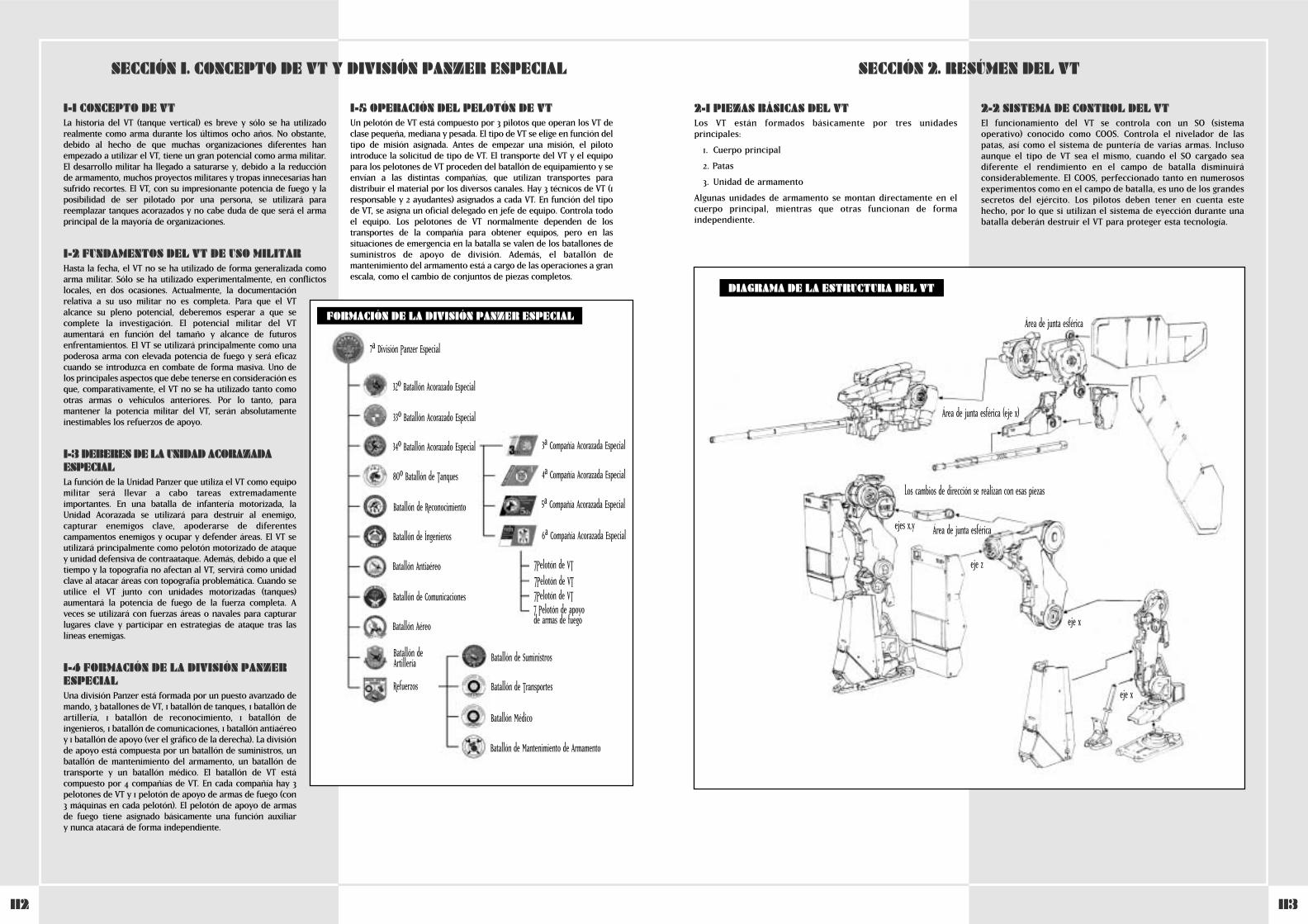
113112
2-1 PIEZAS BÁSICAS DEL VTLos VT están formados básicamente por tres unidadesprincipales:
1. Cuerpo principal
2. Patas
3. Unidad de armamento
Algunas unidades de armamento se montan directamente en elcuerpo principal, mientras que otras funcionan de formaindependiente.
2-2 SISTEMA DE CONTROL DEL VTEl funcionamiento del VT se controla con un SO (sistemaoperativo) conocido como COOS. Controla el nivelador de laspatas, así como el sistema de puntería de varias armas. Inclusoaunque el tipo de VT sea el mismo, cuando el SO cargado seadiferente el rendimiento en el campo de batalla disminuiráconsiderablemente. El COOS, perfeccionado tanto en numerososexperimentos como en el campo de batalla, es uno de los grandessecretos del ejército. Los pilotos deben tener en cuenta estehecho, por lo que si utilizan el sistema de eyección durante unabatalla deberán destruir el VT para proteger esta tecnología.
SECCIÓN 1. CONCEPTO DE VT Y DIVISIÓN PANZER ESPECIAL SECCIÓN 2. RESÚMEN DEL VT
DIAGRAMA DE LA ESTRUCTURA DEL VT
Área de junta esférica (eje x)
ejes x,y
eje z
eje x
eje x
Los cambios de dirección se realizan con esas piezas
Área de junta esférica
Área de junta esférica
1-1 CONCEPTO DE VTLa historia del VT (tanque vertical) es breve y sólo se ha utilizadorealmente como arma durante los últimos ocho años. No obstante,debido al hecho de que muchas organizaciones diferentes hanempezado a utilizar el VT, tiene un gran potencial como arma militar.El desarrollo militar ha llegado a saturarse y, debido a la reducciónde armamento, muchos proyectos militares y tropas innecesarias hansufrido recortes. El VT, con su impresionante potencia de fuego y laposibilidad de ser pilotado por una persona, se utilizará parareemplazar tanques acorazados y no cabe duda de que será el armaprincipal de la mayoría de organizaciones.
1-2 FUNDAMENTOS DEL VT DE USO MILITARHasta la fecha, el VT no se ha utilizado de forma generalizada comoarma militar. Sólo se ha utilizado experimentalmente, en conflictoslocales, en dos ocasiones. Actualmente, la documentaciónrelativa a su uso militar no es completa. Para que el VTalcance su pleno potencial, deberemos esperar a que secomplete la investigación. El potencial militar del VTaumentará en función del tamaño y alcance de futurosenfrentamientos. El VT se utilizará principalmente como unapoderosa arma con elevada potencia de fuego y será eficazcuando se introduzca en combate de forma masiva. Uno delos principales aspectos que debe tenerse en consideración esque, comparativamente, el VT no se ha utilizado tanto comootras armas o vehículos anteriores. Por lo tanto, paramantener la potencia militar del VT, serán absolutamenteinestimables los refuerzos de apoyo.
1-3 DEBERES DE LA UNIDAD ACORAZADAESPECIAL La función de la Unidad Panzer que utiliza el VT como equipomilitar será llevar a cabo tareas extremadamenteimportantes. En una batalla de infantería motorizada, laUnidad Acorazada se utilizará para destruir al enemigo,capturar enemigos clave, apoderarse de diferentescampamentos enemigos y ocupar y defender áreas. El VT seutilizará principalmente como pelotón motorizado de ataquey unidad defensiva de contraataque. Además, debido a que eltiempo y la topografía no afectan al VT, servirá como unidadclave al atacar áreas con topografía problemática. Cuando seutilice el VT junto con unidades motorizadas (tanques)aumentará la potencia de fuego de la fuerza completa. Aveces se utilizará con fuerzas áreas o navales para capturarlugares clave y participar en estrategias de ataque tras laslíneas enemigas.
1-4 FORMACIÓN DE LA DIVISIÓN PANZERESPECIALUna división Panzer está formada por un puesto avanzado demando, 3 batallones de VT, 1 batallón de tanques, 1 batallón deartillería, 1 batallón de reconocimiento, 1 batallón deingenieros, 1 batallón de comunicaciones, 1 batallón antiaéreoy 1 batallón de apoyo (ver el gráfico de la derecha). La divisiónde apoyo está compuesta por un batallón de suministros, unbatallón de mantenimiento del armamento, un batallón detransporte y un batallón médico. El batallón de VT estácompuesto por 4 compañías de VT. En cada compañía hay 3pelotones de VT y 1 pelotón de apoyo de armas de fuego (con3 máquinas en cada pelotón). El pelotón de apoyo de armasde fuego tiene asignado básicamente una función auxiliar y nunca atacará de forma independiente.
1-5 OPERACIÓN DEL PELOTÓN DE VTUn pelotón de VT está compuesto por 3 pilotos que operan los VT declase pequeña, mediana y pesada. El tipo de VT se elige en función deltipo de misión asignada. Antes de empezar una misión, el pilotointroduce la solicitud de tipo de VT. El transporte del VT y el equipopara los pelotones de VT proceden del batallón de equipamiento y seenvían a las distintas compañías, que utilizan transportes paradistribuir el material por los diversos canales. Hay 3 técnicos de VT (1responsable y 2 ayudantes) asignados a cada VT. En función del tipode VT, se asigna un oficial delegado en jefe de equipo. Controla todoel equipo. Los pelotones de VT normalmente dependen de lostransportes de la compañía para obtener equipos, pero en lassituaciones de emergencia en la batalla se valen de los batallones desuministros de apoyo de división. Además, el batallón demantenimiento del armamento está a cargo de las operaciones a granescala, como el cambio de conjuntos de piezas completos.
7ªa División Panzer Especial
32ºo Batallón Acorazado Especial
33oº Batallón Acorazado Especial
34oº Batallón Acorazado Especial 3ªa Compañía Acorazada Especial
4ªa Compañía Acorazada Especial
5aª Compañía Acorazada Especial
6aª Compañía Acorazada Especial
‡Pelotón de VT‡Pelotón de VT‡Pelotón de VT‡ Pelotón de apoyode armas de fuego
Batallón de Suministros
Batallón de Transportes
Batallón Médico
Batallón de Mantenimiento de Armamento
80ºo Batallón de Tanques
Batallón de Reconocimiento
Batallón de Ingenieros
Batallón Antiaéreo
Batallón de Comunicaciones
Batallón Aéreo
Batallón de Artillería
Refuerzos
FORMACIÓN DE LA DIVISIÓN PANZER ESPECIAL
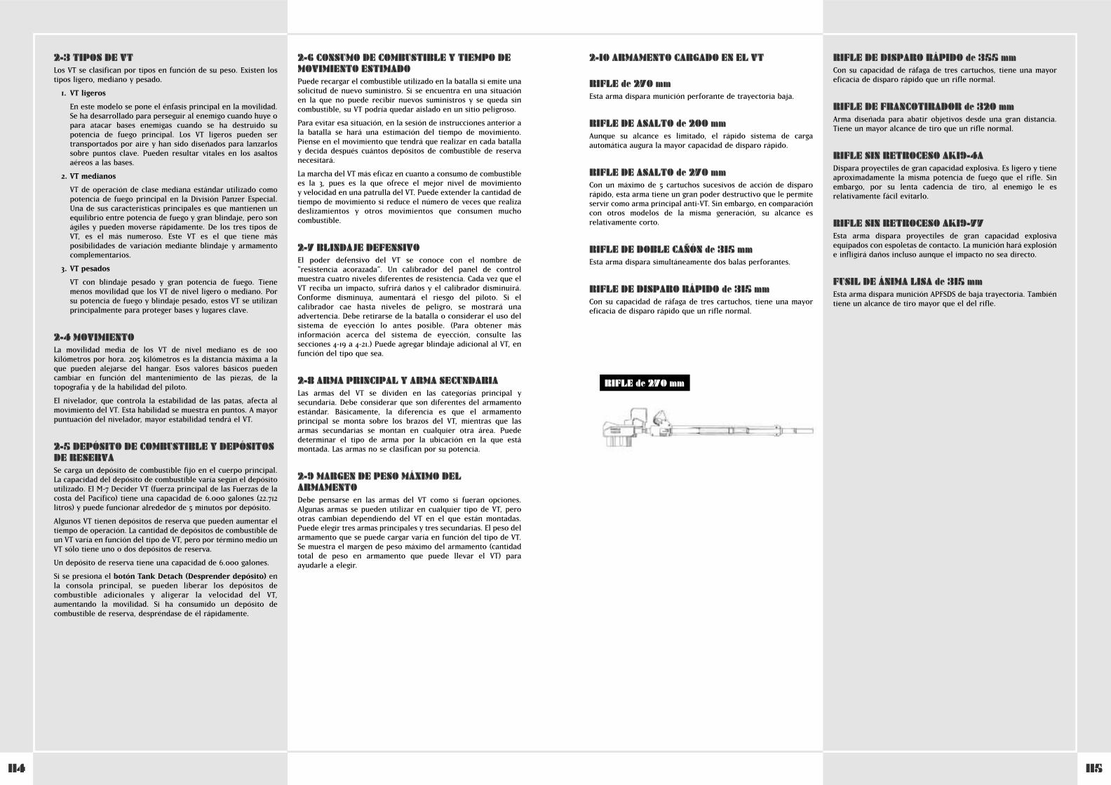
115114
2-10 ARMAMENTO CARGADO EN EL VT
RIFLE de 270 mmEsta arma dispara munición perforante de trayectoria baja.
RIFLE DE ASALTO de 200 mmAunque su alcance es limitado, el rápido sistema de cargaautomática augura la mayor capacidad de disparo rápido.
RIFLE DE ASALTO de 270 mmCon un máximo de 5 cartuchos sucesivos de acción de disparorápido, esta arma tiene un gran poder destructivo que le permiteservir como arma principal anti-VT. Sin embargo, en comparacióncon otros modelos de la misma generación, su alcance esrelativamente corto.
RIFLE DE DOBLE CAÑÓN de 315 mmEsta arma dispara simultáneamente dos balas perforantes.
RIFLE DE DISPARO RÁPIDO de 315 mmCon su capacidad de ráfaga de tres cartuchos, tiene una mayoreficacia de disparo rápido que un rifle normal.
RIFLE DE DISPARO RÁPIDO de 355 mmCon su capacidad de ráfaga de tres cartuchos, tiene una mayoreficacia de disparo rápido que un rifle normal.
RIFLE DE FRANCOTIRADOR de 320 mmArma diseñada para abatir objetivos desde una gran distancia.Tiene un mayor alcance de tiro que un rifle normal.
RIFLE SIN RETROCESO AK19-4ADispara proyectiles de gran capacidad explosiva. Es ligero y tieneaproximadamente la misma potencia de fuego que el rifle. Sinembargo, por su lenta cadencia de tiro, al enemigo le esrelativamente fácil evitarlo.
RIFLE SIN RETROCESO AK19-77Esta arma dispara proyectiles de gran capacidad explosivaequipados con espoletas de contacto. La munición hará explosión e infligirá daños incluso aunque el impacto no sea directo.
FUSIL DE ÁNIMA LISA de 315 mmEsta arma dispara munición APFSDS de baja trayectoria. Tambiéntiene un alcance de tiro mayor que el del rifle.
2-3 TIPOS DE VTLos VT se clasifican por tipos en función de su peso. Existen lostipos ligero, mediano y pesado.
1. VT ligeros
En este modelo se pone el énfasis principal en la movilidad.Se ha desarrollado para perseguir al enemigo cuando huye opara atacar bases enemigas cuando se ha destruido supotencia de fuego principal. Los VT ligeros pueden sertransportados por aire y han sido diseñados para lanzarlossobre puntos clave. Pueden resultar vitales en los asaltosaéreos a las bases.
2. VT medianos
VT de operación de clase mediana estándar utilizado comopotencia de fuego principal en la División Panzer Especial.Una de sus características principales es que mantienen unequilibrio entre potencia de fuego y gran blindaje, pero sonágiles y pueden moverse rápidamente. De los tres tipos deVT, es el más numeroso. Este VT es el que tiene másposibilidades de variación mediante blindaje y armamentocomplementarios.
3. VT pesados
VT con blindaje pesado y gran potencia de fuego. Tienemenos movilidad que los VT de nivel ligero o mediano. Porsu potencia de fuego y blindaje pesado, estos VT se utilizanprincipalmente para proteger bases y lugares clave.
2-4 MOVIMIENTOLa movilidad media de los VT de nivel mediano es de 100kilómetros por hora. 205 kilómetros es la distancia máxima a laque pueden alejarse del hangar. Esos valores básicos puedencambiar en función del mantenimiento de las piezas, de latopografía y de la habilidad del piloto.
El nivelador, que controla la estabilidad de las patas, afecta almovimiento del VT. Esta habilidad se muestra en puntos. A mayorpuntuación del nivelador, mayor estabilidad tendrá el VT.
2-5 DEPÓSITO DE COMBUSTIBLE Y DEPÓSITOSDE RESERVASe carga un depósito de combustible fijo en el cuerpo principal.La capacidad del depósito de combustible varía según el depósitoutilizado. El M-7 Decider VT (fuerza principal de las Fuerzas de lacosta del Pacífico) tiene una capacidad de 6.000 galones (22.712litros) y puede funcionar alrededor de 5 minutos por depósito.
Algunos VT tienen depósitos de reserva que pueden aumentar eltiempo de operación. La cantidad de depósitos de combustible deun VT varía en función del tipo de VT, pero por término medio unVT sólo tiene uno o dos depósitos de reserva.
Un depósito de reserva tiene una capacidad de 6.000 galones.
Si se presiona el botón Tank Detach (Desprender depósito) enla consola principal, se pueden liberar los depósitos decombustible adicionales y aligerar la velocidad del VT,aumentando la movilidad. Si ha consumido un depósito decombustible de reserva, despréndase de él rápidamente.
2-6 CONSUMO DE COMBUSTIBLE Y TIEMPO DEMOVIMIENTO ESTIMADOPuede recargar el combustible utilizado en la batalla si emite unasolicitud de nuevo suministro. Si se encuentra en una situaciónen la que no puede recibir nuevos suministros y se queda sincombustible, su VT podría quedar aislado en un sitio peligroso.
Para evitar esa situación, en la sesión de instrucciones anterior ala batalla se hará una estimación del tiempo de movimiento.Piense en el movimiento que tendrá que realizar en cada batallay decida después cuántos depósitos de combustible de reservanecesitará.
La marcha del VT más eficaz en cuanto a consumo de combustiblees la 3ª, pues es la que ofrece el mejor nivel de movimiento y velocidad en una patrulla del VT. Puede extender la cantidad detiempo de movimiento si reduce el número de veces que realizadeslizamientos y otros movimientos que consumen muchocombustible.
2-7 BLINDAJE DEFENSIVOEl poder defensivo del VT se conoce con el nombre de“resistencia acorazada”. Un calibrador del panel de controlmuestra cuatro niveles diferentes de resistencia. Cada vez que elVT reciba un impacto, sufrirá daños y el calibrador disminuirá.Conforme disminuya, aumentará el riesgo del piloto. Si elcalibrador cae hasta niveles de peligro, se mostrará unaadvertencia. Debe retirarse de la batalla o considerar el uso delsistema de eyección lo antes posible. (Para obtener másinformación acerca del sistema de eyección, consulte lassecciones 4-19 a 4-21.) Puede agregar blindaje adicional al VT, enfunción del tipo que sea.
2-8 ARMA PRINCIPAL Y ARMA SECUNDARIALas armas del VT se dividen en las categorías principal ysecundaria. Debe considerar que son diferentes del armamentoestándar. Básicamente, la diferencia es que el armamentoprincipal se monta sobre los brazos del VT, mientras que lasarmas secundarias se montan en cualquier otra área. Puededeterminar el tipo de arma por la ubicación en la que estámontada. Las armas no se clasifican por su potencia.
2-9 MARGEN DE PESO MÁXIMO DELARMAMENTODebe pensarse en las armas del VT como si fueran opciones.Algunas armas se pueden utilizar en cualquier tipo de VT, perootras cambian dependiendo del VT en el que están montadas.Puede elegir tres armas principales y tres secundarias. El peso delarmamento que se puede cargar varía en función del tipo de VT.Se muestra el margen de peso máximo del armamento (cantidadtotal de peso en armamento que puede llevar el VT) paraayudarle a elegir.
RIFLE de 270 mm
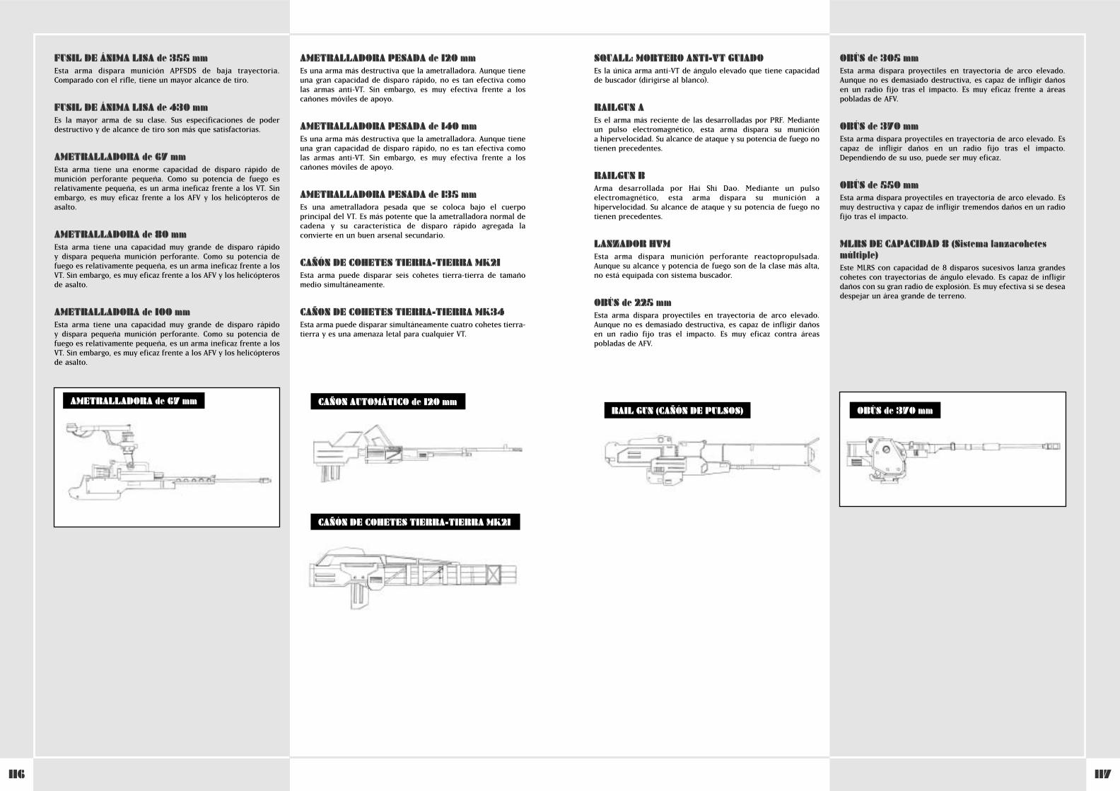
117116
SQUALL: MORTERO ANTI-VT GUIADO Es la única arma anti-VT de ángulo elevado que tiene capacidadde buscador (dirigirse al blanco).
RAILGUN A Es el arma más reciente de las desarrolladas por PRF. Medianteun pulso electromagnético, esta arma dispara su munición a hipervelocidad. Su alcance de ataque y su potencia de fuego notienen precedentes.
RAILGUN BArma desarrollada por Hai Shi Dao. Mediante un pulsoelectromagnético, esta arma dispara su munición ahipervelocidad. Su alcance de ataque y su potencia de fuego notienen precedentes.
LANZADOR HVMEsta arma dispara munición perforante reactopropulsada.Aunque su alcance y potencia de fuego son de la clase más alta,no está equipada con sistema buscador.
OBÚS de 225 mmEsta arma dispara proyectiles en trayectoria de arco elevado.Aunque no es demasiado destructiva, es capaz de infligir dañosen un radio fijo tras el impacto. Es muy eficaz contra áreaspobladas de AFV.
OBÚS de 305 mmEsta arma dispara proyectiles en trayectoria de arco elevado.Aunque no es demasiado destructiva, es capaz de infligir dañosen un radio fijo tras el impacto. Es muy eficaz frente a áreaspobladas de AFV.
OBÚS de 370 mmEsta arma dispara proyectiles en trayectoria de arco elevado. Escapaz de infligir daños en un radio fijo tras el impacto.Dependiendo de su uso, puede ser muy eficaz.
OBÚS de 550 mmEsta arma dispara proyectiles en trayectoria de arco elevado. Esmuy destructiva y capaz de infligir tremendos daños en un radiofijo tras el impacto.
MLRS DE CAPACIDAD 8 (Sistema lanzacohetesmúltiple)Este MLRS con capacidad de 8 disparos sucesivos lanza grandescohetes con trayectorias de ángulo elevado. Es capaz de infligirdaños con su gran radio de explosión. Es muy efectiva si se deseadespejar un área grande de terreno.
FUSIL DE ÁNIMA LISA de 355 mmEsta arma dispara munición APFSDS de baja trayectoria.Comparado con el rifle, tiene un mayor alcance de tiro.
FUSIL DE ÁNIMA LISA de 430 mmEs la mayor arma de su clase. Sus especificaciones de poderdestructivo y de alcance de tiro son más que satisfactorias.
AMETRALLADORA de 67 mmEsta arma tiene una enorme capacidad de disparo rápido demunición perforante pequeña. Como su potencia de fuego esrelativamente pequeña, es un arma ineficaz frente a los VT. Sinembargo, es muy eficaz frente a los AFV y los helicópteros deasalto.
AMETRALLADORA de 80 mmEsta arma tiene una capacidad muy grande de disparo rápido y dispara pequeña munición perforante. Como su potencia defuego es relativamente pequeña, es un arma ineficaz frente a losVT. Sin embargo, es muy eficaz frente a los AFV y los helicópterosde asalto.
AMETRALLADORA de 100 mmEsta arma tiene una capacidad muy grande de disparo rápido y dispara pequeña munición perforante. Como su potencia defuego es relativamente pequeña, es un arma ineficaz frente a losVT. Sin embargo, es muy eficaz frente a los AFV y los helicópterosde asalto.
AMETRALLADORA PESADA de 120 mmEs una arma más destructiva que la ametralladora. Aunque tieneuna gran capacidad de disparo rápido, no es tan efectiva comolas armas anti-VT. Sin embargo, es muy efectiva frente a loscañones móviles de apoyo.
AMETRALLADORA PESADA de 140 mmEs una arma más destructiva que la ametralladora. Aunque tieneuna gran capacidad de disparo rápido, no es tan efectiva comolas armas anti-VT. Sin embargo, es muy efectiva frente a loscañones móviles de apoyo.
AMETRALLADORA PESADA de 135 mmEs una ametralladora pesada que se coloca bajo el cuerpoprincipal del VT. Es más potente que la ametralladora normal decadena y su característica de disparo rápido agregada laconvierte en un buen arsenal secundario.
CAÑÓN DE COHETES TIERRA-TIERRA MK21Esta arma puede disparar seis cohetes tierra-tierra de tamañomedio simultáneamente.
CAÑON DE COHETES TIERRA-TIERRA MK34Esta arma puede disparar simultáneamente cuatro cohetes tierra-tierra y es una amenaza letal para cualquier VT.
RAIL GUN (CAÑÓN DE PULSOS) OBÚS de 370 mmAMETRALLADORA de 67 mm CAÑON AUTOMÁTICO de 120 mm
CAÑÓN DE COHETES TIERRA-TIERRA MK21
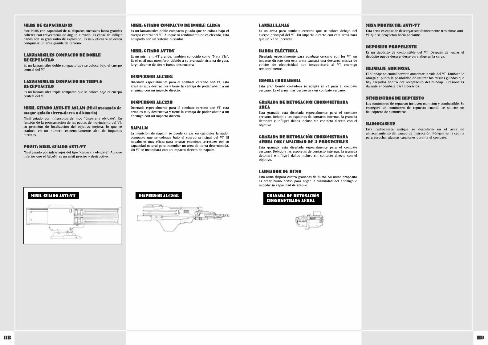
119118
LANZALLAMASEs un arma para combate cercano que se coloca debajo delcuerpo principal del VT. Un impacto directo con esta arma haráque un VT se incendie.
BARRA ELÉCTRICADiseñada especialmente para combate cercano con los VT, unimpacto directo con esta arma causará una descarga masiva devoltios de electricidad que incapacitará al VT enemigotemporalmente.
BOMBA CORTADORAEsta gran bomba cortadora se adapta al VT para el combatecercano. Es el arma más destructiva en combate cercano.
GRANADA DE DETONACIÓN CRONOMETRADAÁREAEsta granada está diseñada especialmente para el combatecercano. Debido a las espoletas de contacto internas, la granadadetonará e infligirá daños incluso sin contacto directo con elobjetivo.
GRANADA DE DETONACIÓN CRONOMETRADAAÉREA CON CAPACIDAD DE 3 PROYECTILESEsta granada está diseñada especialmente para el combatecercano. Debido a las espoletas de contacto internas, la granadadetonará e infligirá daños incluso sin contacto directo con elobjetivo.
CARGADOR DE HUMOEsta arma dispara cuatro granadas de humo. Su único propósitoes crear humo denso para cegar la visibilidad del enemigo eimpedir su capacidad de ataque.
MINA PROYECTIL ANTI-VTEsta arma es capaz de descargar simultáneamente tres minas anti-VT que se proyectan hacia adelante.
DEPÓSITO PROPELENTEEs un depósito de combustible del VT. Después de vaciar eldepósito puede desprenderse para aligerar la carga.
BLINDAJE ADICIONALEl blindaje adicional permite aumentar la vida del VT. También leotorga al piloto la posibilidad de utilizar los misiles guiados quehay cargados dentro del receptáculo del blindaje. Presione F1durante el combate para liberarlos.
SUMINISTROS DE REPUESTOLos suministros de repuesto incluyen munición y combustible. Seentregará un suministro de repuesto cuando se solicite unhelicóptero de suministros.
RADIOCASETEEsta radiocasete antigua se descubrió en el área dealmacenamiento del campo de instrucción. Póngala en la cabinapara escuchar algunas canciones durante el combate.
MLRS DE CAPACIDAD 12Este MLRS con capacidad de 12 disparos sucesivos lanza grandescohetes con trayectorias de ángulo elevado. Es capaz de infligirdaños con su gran radio de explosión. Es muy eficaz si se deseaconquistar un área grande de terreno.
LANZAMISILES COMPACTO DE DOBLERECEPTÁCULOEs un lanzamisiles doble compacto que se coloca bajo el cuerpocentral del VT.
LANZAMISILES COMPACTO DE TRIPLERECEPTÁCULOEs un lanzamisiles triple compacto que se coloca bajo el cuerpocentral del VT.
MISIL GUIADO ANTI-VT ASLAM (Misil avanzado deataque guiado tierra-tierra a distancia)Misil guiado por infrarrojos del tipo “dispara y olvídate”. Enfunción de la programación de las pautas de movimiento del VT,su precisión de localización del objetivo mejora, lo que setraduce en un número extremadamente alto de impactosdirectos.
POZIT: MISIL GUIADO ANTI-VTMisil guiado por infrarrojos del tipo “dispara y olvídate”. Aunqueinferior que el ASLAM, es un misil preciso y destructivo.
MISIL GUIADO COMPACTO DE DOBLE CARGAEs un lanzamisiles doble compacto guiado que se coloca bajo elcuerpo central del VT. Aunque su rendimiento no es elevado, estáequipado con un sistema buscador.
MISIL GUIADO AVTDVEs un misil anti-VT grande, también conocido como "Mata VTs”.Es el misil más mortífero, debido a su avanzado sistema de guía,largo alcance de tiro y fuerza destructora.
DISPERSOR ALC205Diseñada especialmente para el combate cercano con VT, estaarma es muy destructiva y tiene la ventaja de poder abatir a unenemigo con un impacto directo.
DISPERSOR ALC22BDiseñada especialmente para el combate cercano con VT, estaarma es muy destructiva y tiene la ventaja de poder abatir a unenemigo con un impacto directo.
NAPALMLa munición de napalm se puede cargar en cualquier lanzadorcompacto que se coloque bajo el cuerpo principal del VT. Elnapalm es muy eficaz para arrasar enemigos terrestres por sucapacidad natural para incendiar un área de tierra determinada.Un VT se incendiará con un impacto directo de napalm.
DISPERSOR ALC205MISIL GUIADO ANTI-VT GRANADA DE DETONACIÓNCRONOMETRADA AÉREA
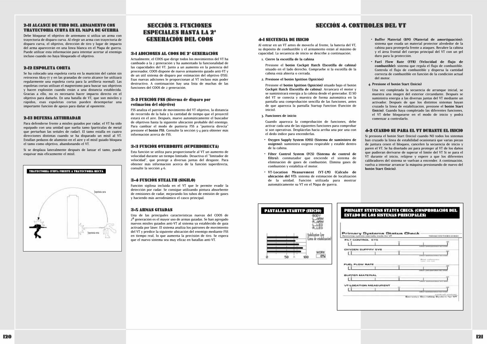
121120
2-11 ALCANCE DE TIRO DEL ARMAMENTO CONTRAYECTORIA CURVA EN EL MAPA DE GUERRADebe bloquear el objetivo de antemano si utiliza un arma contrayectoria de disparo curva. Al elegir un arma con trayectoria dedisparo curva, el objetivo, dirección de tiro y lugar de impactodel arma aparecerán en una línea blanca en el Mapa de guerra.Puede utilizar esta información para intentar acertar al enemigoincluso cuando no haya bloqueado el objetivo.
2-12 ESPOLETA CORTASe ha colocado una espoleta corta en la munición del cañón sinretroceso Ak19-77 y en las granadas de corto alcance (se utilizaráregularmente una espoleta corta para la artillería normal). Lasespoletas cortas utilizan el magnetismo para buscar sus objetivosy hacen explosión cuando están a una distancia establecida.Gracias a ello, no es necesario hacer impacto directo en elobjetivo para dañarlo. En una batalla de VT, que son móviles yrápidos, esas espoletas cortas pueden desempeñar unaimportante función de apoyo para dañar al oponente.
2-13 DEFENSA ANTIRRADARPara defenderse frente a misiles guiados por radar, el VT ha sidoequipado con una unidad que suelta tamo (partículas de metalque perturban las señales de radar). El tamo estalla en cuatrodirecciones distintas cuando se ha disparado un misil al VT.Estallan pedazos de aluminio en el aire y el misil guiado bloqueael tamo como objetivo, abandonando el VT.
Si se desplaza lateralmente después de lanzar el tamo, puedeesquivar más eficazmente el misil.
3-1 ADICIONES AL COOS DE 2ª GENERACIÓNActualmente, el COOS que dirige todos los movimientos del VT hacambiado a la 2ª generación y ha aumentado la funcionalidad delas capacidades del VT. Junto a un aumento en la potencia delprocesador, COOS dispone de nuevo armamento guiado anti-VT yde un útil sistema de disparo por estimación del objetivo (FSS).Esas nuevas adiciones le proporcionan al VT incluso más poderdestructivo. A continuación hay una lista de muchas de lasfunciones del COOS de 2ª generación.
3-2 FUNCIÓN FSS (Sistema de disparo porestimación del objetivo)FSS analiza el patrón de movimiento del VT objetivo, la distanciade recorrido de la bala y la cantidad de tiempo que el proyectilestará en el aire. Después, mueve automáticamente el buscadorde objetivos hasta la siguiente ubicación probable del enemigo.Para cambiar el modo de puntería FSS a "puntería directa"presione el botón FSS. Consulte la sección 5-4 para obtener másinformación acerca de FSS.
3-3 FUNCIÓN OVERDRIVE (SUPERDIRECTA)Esta función se utiliza para proporcionarle al VT un aumento develocidad durante un tiempo limitado. Desactiva el "limitador develocidad", que protege a diversas juntas del desgaste. Paraobtener más información acerca de la función superdirecta,consulte la sección 4-6.
3-4 FUNCIÓN STEALTH (SIGILO)Función sigilosa incluida en el VT que le permite evadir ladetección por radar. Se consigue utilizando pintura absorbentede emisiones de radar, mejorando los tubos de emisión de gasesy haciendo más aerodinámico el casco principal.
3-5 ARMAS GUIADASUna de las principales características nuevas del COOS de 2ªa generación es el mayor uso de armas guiadas. Se han agregadonuevos misiles guiados anti-VT al sistema ya establecido de guíaactivada por láser. El sistema analiza los patrones de movimientodel VT y predice la siguiente ubicación del enemigo mediante FSSen tiempo real, lo que aumenta la precisión de tiro. Se esperaque el nuevo sistema sea muy eficaz en batallas anti-VT.
SECCIÓN 3. FUNCIONESESPECIALES HASTA LA 2ª
GENERACIÓN DEL COOS
TRAYECTORIA CURVA FRENTE A TRAYECTORIA RECTA
Trayectoria curva
Trayectoria recta
4-1 SECUENCIA DE INICIOAl entrar en un VT antes de moverlo al frente, la batería del VT,su depósito de combustible y el armamento están al máximo decapacidad. La secuencia de inicio se describe a continuación.
1. Cierre la escotilla de la cabina
Presione el botón Cockpit Hatch (Escotilla de cabina)situado en el lado derecho. Compruebe si la escotilla de lacabina está abierta o cerrada.
2. Presione el botón Ignition (Ignición)
Presione el botón Ignition (Ignición) situado bajo el botónCockpit Hatch (Escotilla de cabina). Arrancará el motor yse suministrará energía a la cabina desde el generador. El SOdel VT se conecta y muestra de forma automática en lapantalla una comprobación sencilla de las funciones, antesde que aparezca la pantalla Startup Function (Función deinicio).
3. Funciones de inicio
Cuando aparezca la comprobación de funciones, debeactivar cada una de las siguientes funciones para comprobarsi son operativas. Desplácelas hacia arriba una por una conel dedo índice para encenderlas.
• Oxygen Supply System (OSS) (Sistema de suministro deoxígeno): suministra oxígeno respirable y estable dentrode la cabina.
• Filter Control System (FCS) (Sistema de control defiltro): conmutador que enciende el sistema deeliminación de gases de combustión. Elimina gases decombustión y estabiliza el motor.
• VT-Location Measurement (VT-LM) (Cálculo deubicación del VT): sistema de estimación de localizaciónde la unidad. Función utilizada para mostrarautomáticamente su VT en el Mapa de guerra.
• Buffer Material (BM) (Material de amortiguación):sistema que exuda un material protector alrededor de lacabina para protegerla frente a ataques. Recubre la cabinay el área frontal del cuerpo principal del VT con un gelduro para la protección.
• Fuel Flow Rate (FFR) (Velocidad de flujo decombustible): sistema que regula el flujo de combustible.Controla el flujo de combustible y dispersa la cantidadcorrecta de combustible en función de la condición actualdel motor.
4. Presione el botón Start (Inicio)
Una vez completada la secuencia de arranque inicial, semuestra una imagen del exterior circundante. Después sesuministra energía a las diversas juntas del VT mediante unactivador. Después de que los distintos sistemas hayancruzado la línea de estabilización, presione el botón Start(Inicio). Cuando haya completado las diferentes funciones,el VT debe bloquearse en el modo de inicio y podrácomenzar a controlarlo.
4-2 CUANDO SE PARA EL VT DURANTE EL INICIOSi presiona el botón Start (Inicio) cuando NO todos los sistemashan cruzado la línea de estabilidad ocasionará que varias piezasde juntura cesen el bloqueo, cancelen la secuencia de inicio yparen el VT. Se ha diseñado así para proteger al VT de los dañosque pudieran derivarse de superar el límite del VT Si se para elVT durante el inicio, relájese y espere a que los diferentescalibradores del sistema se vuelvan a encender. A continuación,vuelva a intentar arrancar la máquina presionando de nuevo delbotón Start (Inicio).
SECCIÓN 4. CONTROLES DEL VT
PANTALLA STARTUP (INICIO)
Stabilization Line (Línea de estabilización)
PRIMARY SYSTEMS STATUS CHECK (COMPROBACIÓN DELESTADO DE LOS SISTEMAS PRINCIPALES)
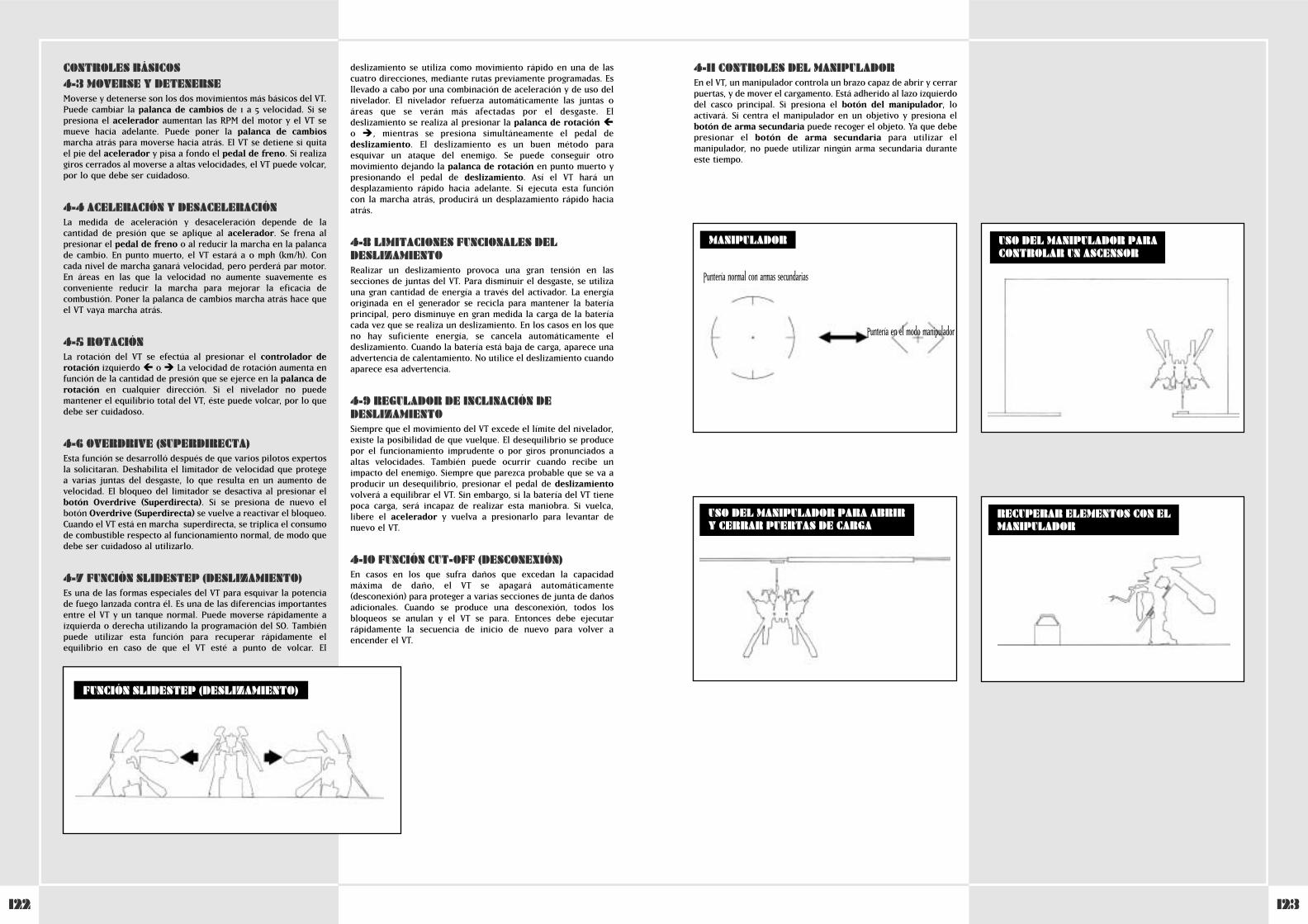
123122
CONTROLES BÁSICOS4-3 MOVERSE Y DETENERSEMoverse y detenerse son los dos movimientos más básicos del VT.Puede cambiar la palanca de cambios de 1ª a 5ª velocidad. Si sepresiona el acelerador aumentan las RPM del motor y el VT semueve hacia adelante. Puede poner la palanca de cambiosmarcha atrás para moverse hacia atrás. El VT se detiene si quitael pie del acelerador y pisa a fondo el pedal de freno. Si realizagiros cerrados al moverse a altas velocidades, el VT puede volcar,por lo que debe ser cuidadoso.
4-4 ACELERACIÓN Y DESACELERACIÓNLa medida de aceleración y desaceleración depende de lacantidad de presión que se aplique al acelerador. Se frena alpresionar el pedal de freno o al reducir la marcha en la palancade cambio. En punto muerto, el VT estará a 0 mph (km/h). Concada nivel de marcha ganará velocidad, pero perderá par motor.En áreas en las que la velocidad no aumente suavemente esconveniente reducir la marcha para mejorar la eficacia decombustión. Poner la palanca de cambios marcha atrás hace queel VT vaya marcha atrás.
4-5 ROTACIÓNLa rotación del VT se efectúa al presionar el controlador derotación izquierdo � o � La velocidad de rotación aumenta enfunción de la cantidad de presión que se ejerce en la palanca derotación en cualquier dirección. Si el nivelador no puedemantener el equilibrio total del VT, éste puede volcar, por lo quedebe ser cuidadoso.
4-6 OVERDRIVE (SUPERDIRECTA)Esta función se desarrolló después de que varios pilotos expertosla solicitaran. Deshabilita el limitador de velocidad que protege a varias juntas del desgaste, lo que resulta en un aumento develocidad. El bloqueo del limitador se desactiva al presionar elbotón Overdrive (Superdirecta). Si se presiona de nuevo elbotón Overdrive (Superdirecta) se vuelve a reactivar el bloqueo.Cuando el VT está en marcha superdirecta, se triplica el consumode combustible respecto al funcionamiento normal, de modo quedebe ser cuidadoso al utilizarlo.
4-7 FUNCIÓN SLIDESTEP (DESLIZAMIENTO)Es una de las formas especiales del VT para esquivar la potenciade fuego lanzada contra él. Es una de las diferencias importantesentre el VT y un tanque normal. Puede moverse rápidamente aizquierda o derecha utilizando la programación del SO. Tambiénpuede utilizar esta función para recuperar rápidamente elequilibrio en caso de que el VT esté a punto de volcar. El
deslizamiento se utiliza como movimiento rápido en una de lascuatro direcciones, mediante rutas previamente programadas. Esllevado a cabo por una combinación de aceleración y de uso delnivelador. El nivelador refuerza automáticamente las juntas oáreas que se verán más afectadas por el desgaste. Eldeslizamiento se realiza al presionar la palanca de rotación �o � ^, mientras se presiona simultáneamente el pedal dedeslizamiento. El deslizamiento es un buen método paraesquivar un ataque del enemigo. Se puede conseguir otromovimiento dejando la palanca de rotación en punto muerto ypresionando el pedal de deslizamiento. Así el VT hará undesplazamiento rápido hacia adelante. Si ejecuta esta funcióncon la marcha atrás, producirá un desplazamiento rápido haciaatrás.
4-8 LIMITACIONES FUNCIONALES DELDESLIZAMIENTORealizar un deslizamiento provoca una gran tensión en lassecciones de juntas del VT. Para disminuir el desgaste, se utilizauna gran cantidad de energía a través del activador. La energíaoriginada en el generador se recicla para mantener la bateríaprincipal, pero disminuye en gran medida la carga de la bateríacada vez que se realiza un deslizamiento. En los casos en los queno hay suficiente energía, se cancela automáticamente eldeslizamiento. Cuando la batería está baja de carga, aparece unaadvertencia de calentamiento. No utilice el deslizamiento cuandoaparece esa advertencia.
4-9 REGULADOR DE INCLINACIÓN DEDESLIZAMIENTOSiempre que el movimiento del VT excede el límite del nivelador,existe la posibilidad de que vuelque. El desequilibrio se producepor el funcionamiento imprudente o por giros pronunciados aaltas velocidades. También puede ocurrir cuando recibe unimpacto del enemigo. Siempre que parezca probable que se va aproducir un desequilibrio, presionar el pedal de deslizamientovolverá a equilibrar el VT. Sin embargo, si la batería del VT tienepoca carga, será incapaz de realizar esta maniobra. Si vuelca,libere el acelerador y vuelva a presionarlo para levantar denuevo el VT.
4-10 FUNCIÓN CUT-OFF (DESCONEXIÓN)En casos en los que sufra daños que excedan la capacidadmáxima de daño, el VT se apagará automáticamente(desconexión) para proteger a varias secciones de junta de dañosadicionales. Cuando se produce una desconexión, todos losbloqueos se anulan y el VT se para. Entonces debe ejecutarrápidamente la secuencia de inicio de nuevo para volver aencender el VT.
FUNCIÓN SLIDESTEP (DESLIZAMIENTO)
4-11 CONTROLES DEL MANIPULADOREn el VT, un manipulador controla un brazo capaz de abrir y cerrarpuertas, y de mover el cargamento. Está adherido al lazo izquierdodel casco principal. Si presiona el botón del manipulador, loactivará. Si centra el manipulador en un objetivo y presiona elbotón de arma secundaria puede recoger el objeto. Ya que debepresionar el botón de arma secundaria para utilizar elmanipulador, no puede utilizar ningún arma secundaria duranteeste tiempo.
USO DEL MANIPULADOR PARACONTROLAR UN ASCENSOR
USO DEL MANIPULADOR PARA ABRIR Y CERRAR PUERTAS DE CARGA
MANIPULADOR
RECUPERAR ELEMENTOS CON ELMANIPULADOR
Puntería normal con armas secundarias
Puntería en el modo manipulador

125124
PANTALLA DEL VT4-12 CAMBIO DE LA CÁMARA PRINCIPALLa perspectiva del VT está determinada por la cámara principal.La imagen se muestra en la cabina. La cámara enfocanormalmente al frente y al centro. Si se presiona el botón de lapalanca de pilotaje izquierda �, �, � o � ^ ̂puede aumentar lasuperficie de área visible. Si presiona el botón de la palanca decontrol puede volver a centrar la vista directamente delante delVT. Al utilizar eso y la pantalla secundaria del VT (descritaposteriormente), podrá mover el VT mejorando su utilidad encombate.
4-13 POLVO Y SUCIEDAD EN LA CÁMARAPRINCIPALEn combate, debe disponer de una visión clara en la pantallaprincipal. En el caso de que la pantalla aparezca gris, con polvo o suciedad, presione el botón de lavado para limpiarla.
PERSPECTIVAS DE CÁMARA
4-14 FUNCIONES DE LA PANTALLA SECUNDARIASi presiona el botón de selección de modo de la pantallasecundaria bajo la pantalla principal, puede cambiar entre cuatromodos.
• Modo de vista frontal
Muestra lo que hay directamente frente al VT. Utilice estavista con la función de cambio de sitio para ver las cosas conmás claridad.
• Modo de vista posterior
Muestra lo que hay directamente detrás del VT. Como en lavista frontal, si utiliza esta vista con la función de cambio desitio puede ver las cosas con más claridad.
• Modo de vista de bloqueo de objetivo
Utilizado para acercar el objetivo bloqueado. Un objetivoque esté muy lejos aparecerá en la pantalla secundariaincluso sin acercarlo.
• Modo de vista aérea (vista de pájaro)
Esta vista muestra el VT desde 50 metros por encima de él.Es útil para ver puntos ciegos y mirar alrededor de objetos.
4-15 EQUIPO DE VISIÓN NOCTURNASe ha incluido un catalejo de visión nocturna en el VT parautilizarlo bajo condiciones de poca luz, como de noche o enentornos llenos de humo. Para utilizar el catalejo, presione elbotón night scope (catalejo nocturno) . El VT utiliza el JGVS-V442 de tipo pasivo, que proyecta luz infrarroja a un sujeto y lomuestra en formato gráfico en la pantalla. El catalejo de visiónnocturna se puede utilizar no sólo en la oscuridad y en áreas conmucho humo, sino también para ayudar a detectar objetivoscamuflados. El catalejo divisa hasta una distancia de unos 2,5kilómetros y la visualización se muestra en la pantalla normal.Cuando se utiliza el catalejo en la oscuridad, los fogonazos de labatalla o de una granada oscurecerán el catalejo temporalmentey no podrá ver.
JCS (Sistema de mando completo)4-16 RESUMEN DE JCSJCS es un sistema que utiliza datos de estrategia de guerra y lainformación más reciente para aumentar la eficacia del VT almáximo. Su propósito principal es suministrar la información másreciente respecto al campo de batalla, a las fuerzas aliadas, alenemigo y a otras compañías y batallones. El sistema estádiseñado para aumentar la eficacia global del VT en combate. Lospilotos de VT así como los jefes de pelotón deben ser capaces deutilizarlo eficazmente.
JCS utiliza una red que va desde el puesto de mando detransporte de los VT hasta los puestos de mando de las distintascompañías y batallones, lo que ayuda a llevar las noticias másrecientes hacia y desde las personas apropiadas. Este sistemaenvía mensajes desde las pantallas de vídeo del VT, satélites dereconocimiento y otras divisiones de mando y edita los datos entiempo real en los puestos de mando del batallón. Despuésanaliza los datos y los envía a los distintos pelotones. Losdiferentes datos se envían al VT a través de una red decomunicaciones y se muestran en las diversas pantallas de lacabina. Gracias a este sistema, los pilotos pueden consultar elmapa y las ubicaciones del enemigo, y administrar el fuego deapoyo a sus fuerzas.
GRÁFICO RESUMEN DE LAS REDES DELSISTEMA DE MANDO COMPLETO
Centro de mando de transporte de VTVT
Avión de reconocimiento
Satélite de reconocimiento
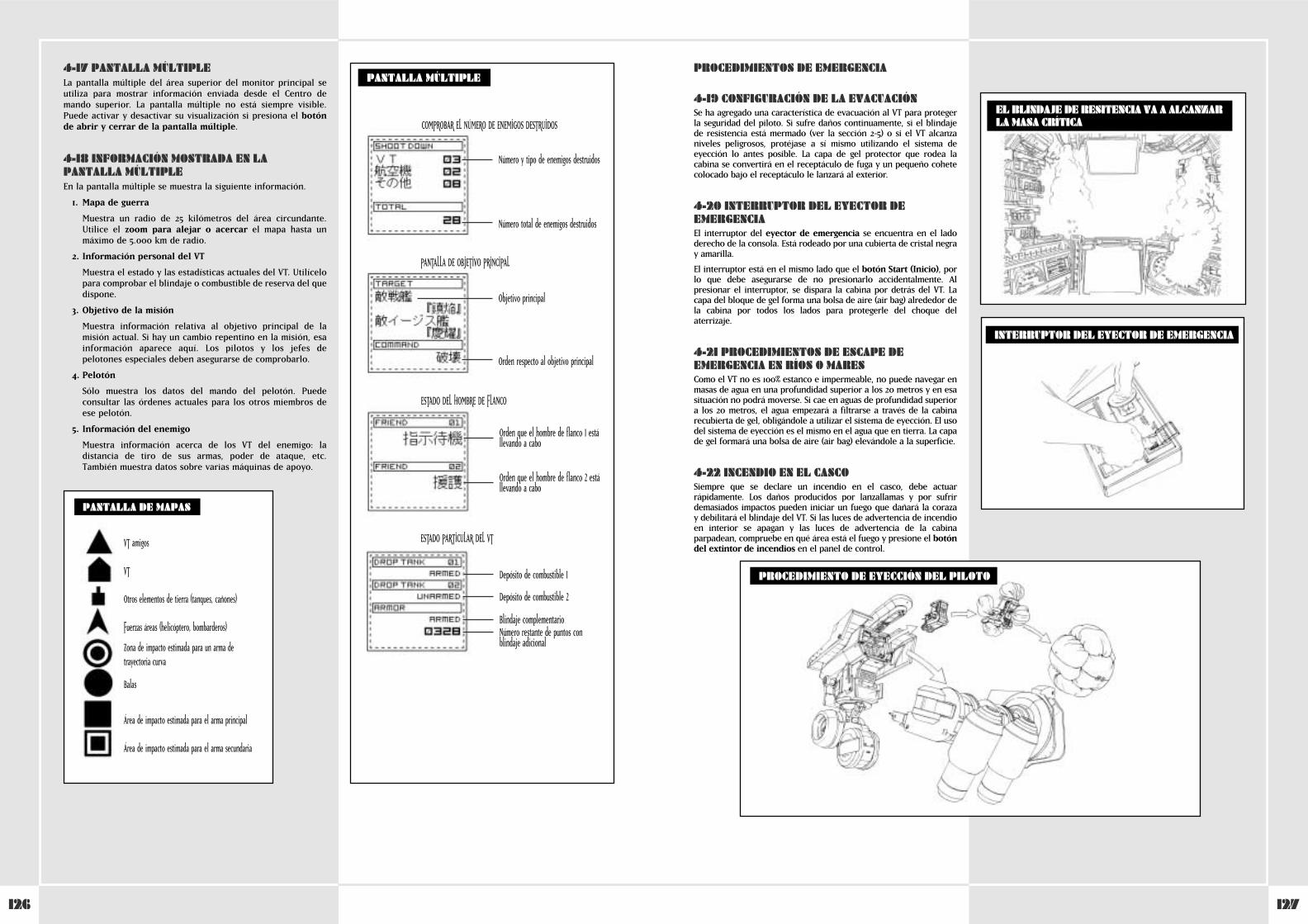
127126
4-17 PANTALLA MÚLTIPLELa pantalla múltiple del área superior del monitor principal seutiliza para mostrar información enviada desde el Centro demando superior. La pantalla múltiple no está siempre visible.Puede activar y desactivar su visualización si presiona el botónde abrir y cerrar de la pantalla múltiple.
4-18 INFORMACIÓN MOSTRADA EN LAPANTALLA MÚLTIPLEEn la pantalla múltiple se muestra la siguiente información.
1. Mapa de guerra
Muestra un radio de 25 kilómetros del área circundante.Utilice el zoom para alejar o acercar el mapa hasta unmáximo de 5.000 km de radio.
2. Información personal del VT
Muestra el estado y las estadísticas actuales del VT. Utilícelopara comprobar el blindaje o combustible de reserva del quedispone.
3. Objetivo de la misión
Muestra información relativa al objetivo principal de lamisión actual. Si hay un cambio repentino en la misión, esainformación aparece aquí. Los pilotos y los jefes depelotones especiales deben asegurarse de comprobarlo.
4. Pelotón
Sólo muestra los datos del mando del pelotón. Puedeconsultar las órdenes actuales para los otros miembros deese pelotón.
5. Información del enemigo
Muestra información acerca de los VT del enemigo: ladistancia de tiro de sus armas, poder de ataque, etc.También muestra datos sobre varias máquinas de apoyo.
VT amigos
VT
Otros elementos de tierra (tanques, cañones)
Fuerzas áreas (helicóptero, bombarderos)
Zona de impacto estimada para un arma de trayectoria curva
Balas
Área de impacto estimada para el arma principal
Área de impacto estimada para el arma secundaria
PANTALLA DE MAPAS
PANTALLA MÚLTIPLE
COMPROBAR EL NÚMERO DE ENEMIGOS DESTRUIDOS
Número y tipo de enemigos destruidos
Número total de enemigos destruidos
Objetivo principal
Orden respecto al objetivo principal
PANTALLA DE OBJETIVO PRINCIPAL
Orden que el hombre de flanco 1 estállevando a cabo
Orden que el hombre de flanco 2 estállevando a cabo
ESTADO DEL HOMBRE DE FLANCO
Depósito de combustible 1
Depósito de combustible 2
Blindaje complementarioNúmero restante de puntos conblindaje adicional
ESTADO PARTICULAR DEL VT
PROCEDIMIENTOS DE EMERGENCIA
4-19 CONFIGURACIÓN DE LA EVACUACIÓNSe ha agregado una característica de evacuación al VT para protegerla seguridad del piloto. Si sufre daños continuamente, si el blindajede resistencia está mermado (ver la sección 2-5) o si el VT alcanzaniveles peligrosos, protéjase a sí mismo utilizando el sistema deeyección lo antes posible. La capa de gel protector que rodea lacabina se convertirá en el receptáculo de fuga y un pequeño cohetecolocado bajo el receptáculo le lanzará al exterior.
4-20 INTERRUPTOR DEL EYECTOR DEEMERGENCIAEl interruptor del eyector de emergencia se encuentra en el ladoderecho de la consola. Está rodeado por una cubierta de cristal negra y amarilla.
El interruptor está en el mismo lado que el botón Start (Inicio), porlo que debe asegurarse de no presionarlo accidentalmente. Alpresionar el interruptor, se dispara la cabina por detrás del VT. Lacapa del bloque de gel forma una bolsa de aire (air bag) alrededor dela cabina por todos los lados para protegerle del choque delaterrizaje.
4-21 PROCEDIMIENTOS DE ESCAPE DEEMERGENCIA EN RÍOS O MARESComo el VT no es 100% estanco e impermeable, no puede navegar enmasas de agua en una profundidad superior a los 20 metros y en esasituación no podrá moverse. Si cae en aguas de profundidad superior a los 20 metros, el agua empezará a filtrarse a través de la cabinarecubierta de gel, obligándole a utilizar el sistema de eyección. El usodel sistema de eyección es el mismo en el agua que en tierra. La capade gel formará una bolsa de aire (air bag) elevándole a la superficie.
4-22 INCENDIO EN EL CASCOSiempre que se declare un incendio en el casco, debe actuarrápidamente. Los daños producidos por lanzallamas y por sufrirdemasiados impactos pueden iniciar un fuego que dañará la coraza y debilitará el blindaje del VT. Si las luces de advertencia de incendioen interior se apagan y las luces de advertencia de la cabinaparpadean, compruebe en qué área está el fuego y presione el botóndel extintor de incendios en el panel de control.
INTERRUPTOR DEL EYECTOR DE EMERGENCIA
PROCEDIMIENTO DE EYECCIÓN DEL PILOTO
EL BLINDAJE DE RESITENCIA VA A ALCANZARLA MASA CRÍTICA
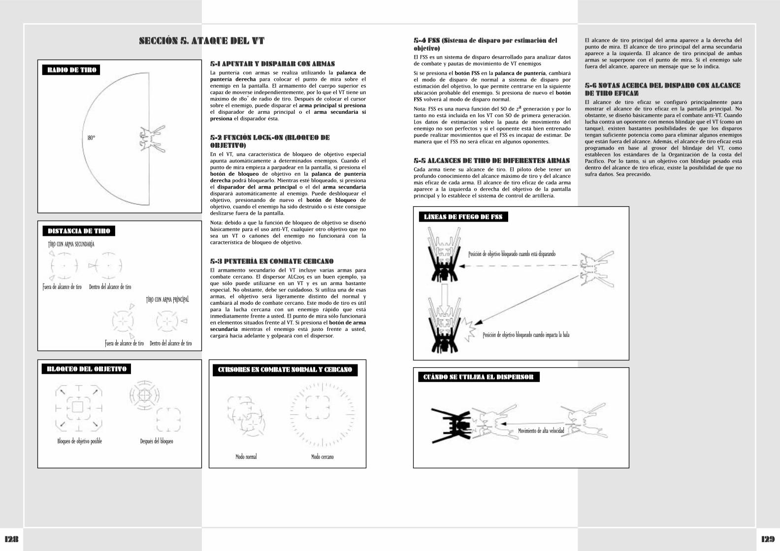
129128
5-1 APUNTAR Y DISPARAR CON ARMASLa puntería con armas se realiza utilizando la palanca depuntería derecha para colocar el punto de mira sobre elenemigo en la pantalla. El armamento del cuerpo superior escapaz de moverse independientemente, por lo que el VT tiene unmáximo de 180 º̊ de radio de tiro. Después de colocar el cursorsobre el enemigo, puede disparar el arma principal si presionael disparador de arma principal o el arma secundaria sipresiona el disparador ésta.
5-2 FUNCIÓN LOCK-ON (BLOQUEO DEOBJETIVO)En el VT, una característica de bloqueo de objetivo especialapunta automáticamente a determinados enemigos. Cuando elpunto de mira empieza a parpadear en la pantalla, si presiona elbotón de bloqueo de objetivo en la palanca de punteríaderecha podrá bloquearlo. Mientras esté bloqueado, si presionael disparador del arma principal o el del arma secundariadisparará automáticamente al enemigo. Puede desbloquear elobjetivo, presionando de nuevo el botón de bloqueo deobjetivo, cuando el enemigo ha sido destruido o si éste consiguedeslizarse fuera de la pantalla.
Nota: debido a que la función de bloqueo de objetivo se diseñóbásicamente para el uso anti-VT, cualquier otro objetivo que nosea un VT o cañones del enemigo no funcionará con lacaracterística de bloqueo de objetivo.
5-3 PUNTERÍA EN COMBATE CERCANOEl armamento secundario del VT incluye varias armas paracombate cercano. El dispersor ALC205 es un buen ejemplo, yaque sólo puede utilizarse en un VT y es un arma bastanteespecial. No obstante, debe ser cuidadoso. Si utiliza una de esasarmas, el objetivo será ligeramente distinto del normal ycambiará al modo de combate cercano. Este modo de tiro es útilpara la lucha cercana con un enemigo rápido que estáinmediatamente frente a usted. El punto de mira sólo funcionaráen elementos situados frente al VT. Si presiona el botón de armasecundaria mientras el enemigo está justo frente a usted,cargará hacia adelante y golpeará con el dispersor.
SECCIÓN 5. ATAQUE DEL VT
BLOQUEO DEL OBJETIVO
RADIO DE TIRO
DISTANCIA DE TIRO
180°
TIRO CON ARMA SECUNDARIA
Fuera de alcance de tiro Dentro del alcance de tiro
TIRO CON ARMA PRINCIPAL
Fuera de alcance de tiro Dentro del alcance de tiro
Bloqueo de objetivo posible Después del bloqueo
CURSORES EN COMBATE NORMAL Y CERCANO
Modo normal Modo cercano
5-4 FSS (Sistema de disparo por estimación delobjetivo)El FSS es un sistema de disparo desarrollado para analizar datosde combate y pautas de movimiento de VT enemigos
Si se presiona el botón FSS en la palanca de puntería, cambiaráel modo de disparo de normal a sistema de disparo porestimación del objetivo, lo que permite centrarse en la siguienteubicación probable del enemigo. Si presiona de nuevo el botónFSS volverá al modo de disparo normal.
Nota: FSS es una nueva función del SO de 2aª generación y por lotanto no está incluida en los VT con SO de primera generación.Los datos de estimación sobre la pauta de movimiento delenemigo no son perfectos y si el oponente está bien entrenadopuede realizar movimientos que el FSS es incapaz de estimar. Demanera que el FSS no será eficaz en algunos oponentes.
5-5 ALCANCES DE TIRO DE DIFERENTES ARMASCada arma tiene su alcance de tiro. El piloto debe tener unprofundo conocimiento del alcance máximo de tiro y del alcancemás eficaz de cada arma. El alcance de tiro eficaz de cada armaaparece a la izquierda o derecha del objetivo de la pantallaprincipal y lo establece el sistema de control de artillería.
El alcance de tiro principal del arma aparece a la derecha delpunto de mira. El alcance de tiro principal del arma secundariaaparece a la izquierda. El alcance de tiro principal de ambasarmas se superpone con el punto de mira. Si el enemigo salefuera del alcance, aparece un mensaje que se lo indica.
5-6 NOTAS ACERCA DEL DISPARO CON ALCANCEDE TIRO EFICAZEl alcance de tiro eficaz se configuró principalmente paramostrar el alcance de tiro eficaz en la pantalla principal. Noobstante, se diseñó básicamente para el combate anti-VT. Cuandolucha contra un oponente con menos blindaje que el VT (como untanque), existen bastantes posibilidades de que los disparostengan suficiente potencia como para eliminar algunos enemigosque están fuera del alcance. Además, el alcance de tiro eficaz estáprogramado en base al grosor del blindaje del VT, comoestablecen los estándares de la Organización de la costa delPacífico. Por lo tanto, si un objetivo con blindaje pesado estádentro del alcance de tiro eficaz, existe la posibilidad de que nosufra daños. Sea precavido.
CUÁNDO SE UTILIZA EL DISPERSOR
Movimiento de alta velocidad
LÍNEAS DE FUEGO DE FSS
Posición de objetivo bloqueado cuando está disparando
Posición de objetivo bloqueado cuando impacta la bala
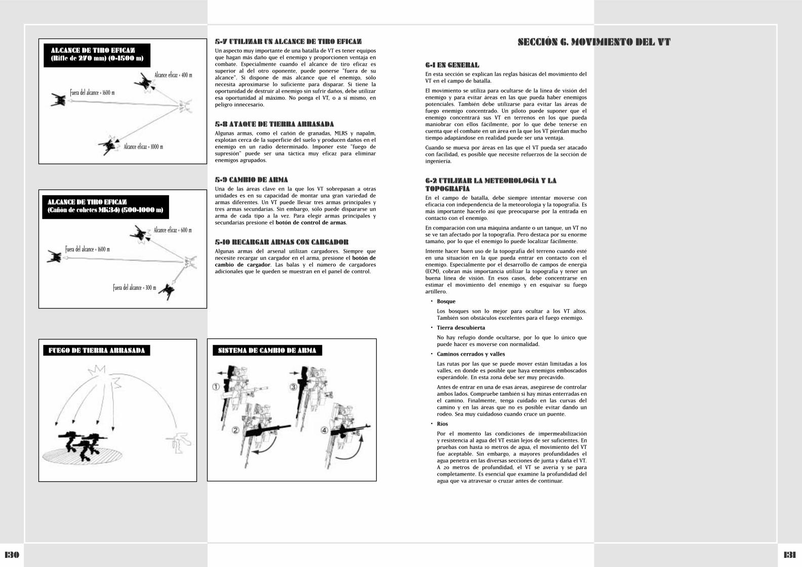
131130
5-7 UTILIZAR UN ALCANCE DE TIRO EFICAZUn aspecto muy importante de una batalla de VT es tener equiposque hagan más daño que el enemigo y proporcionen ventaja encombate. Especialmente cuando el alcance de tiro eficaz essuperior al del otro oponente, puede ponerse "fuera de sualcance". Si dispone de más alcance que el enemigo, sólonecesita aproximarse lo suficiente para disparar. Si tiene laoportunidad de destruir al enemigo sin sufrir daños, debe utilizaresa oportunidad al máximo. No ponga el VT, o a sí mismo, enpeligro innecesario.
5-8 ATAQUE DE TIERRA ARRASADAAlgunas armas, como el cañón de granadas, MLRS y napalm,explotan cerca de la superficie del suelo y producen daños en elenemigo en un radio determinado. Imponer este "fuego desupresión" puede ser una táctica muy eficaz para eliminarenemigos agrupados.
5-9 CAMBIO DE ARMAUna de las áreas clave en la que los VT sobrepasan a otrasunidades es en su capacidad de montar una gran variedad dearmas diferentes. Un VT puede llevar tres armas principales ytres armas secundarias. Sin embargo, sólo puede dispararse unarma de cada tipo a la vez. Para elegir armas principales ysecundarias presione el botón de control de armas.
5-10 RECARGAR ARMAS CON CARGADORAlgunas armas del arsenal utilizan cargadores. Siempre quenecesite recargar un cargador en el arma, presione el botón decambio de cargador. Las balas y el número de cargadoresadicionales que le queden se muestran en el panel de control.
SISTEMA DE CAMBIO DE ARMAFUEGO DE TIERRA ARRASADA
Alcance eficaz = 400 m
Alcance eficaz = 1000 m
Fuera del alcance = 1600 m
ALCANCE DE TIRO EFICAZ (Rifle de 270 mm) (0-1500 m)
ALCANCE DE TIRO EFICAZ (Cañón de cohetes MK34) (500-1000 m)
Alcance eficaz = 600 m
Fuera del alcance = 1600 m
Fuera del alcance = 300 m
6-1 EN GENERALEn esta sección se explican las reglas básicas del movimiento delVT en el campo de batalla.
El movimiento se utiliza para ocultarse de la línea de visión delenemigo y para evitar áreas en las que pueda haber enemigospotenciales. También debe utilizarse para evitar las áreas defuego enemigo concentrado. Un piloto puede suponer que elenemigo concentrará sus VT en terrenos en los que puedamaniobrar con ellos fácilmente, por lo que debe tenerse encuenta que el combate en un área en la que los VT pierdan muchotiempo adaptándose en realidad puede ser una ventaja.
Cuando se mueva por áreas en las que el VT pueda ser atacadocon facilidad, es posible que necesite refuerzos de la sección deingeniería.
6-2 UTILIZAR LA METEOROLOGÍA Y LATOPOGRAFÍAEn el campo de batalla, debe siempre intentar moverse coneficacia con independencia de la meteorología y la topografía. Esmás importante hacerlo así que preocuparse por la entrada encontacto con el enemigo.
En comparación con una máquina andante o un tanque, un VT nose ve tan afectado por la topografía. Pero destaca por su enormetamaño, por lo que el enemigo lo puede localizar fácilmente.
Intente hacer buen uso de la topografía del terreno cuando estéen una situación en la que pueda entrar en contacto con elenemigo. Especialmente por el desarrollo de campos de energía(ECM), cobran más importancia utilizar la topografía y tener unbuena línea de visión. En esos casos, debe concentrarse enestimar el movimiento del enemigo y en esquivar su fuegoartillero.
• Bosque
Los bosques son lo mejor para ocultar a los VT altos.También son obstáculos excelentes para el fuego enemigo.
• Tierra descubierta
No hay refugio donde ocultarse, por lo que lo único quepuede hacer es moverse con normalidad.
• Caminos cerrados y valles
Las rutas por las que se puede mover están limitadas a losvalles, en donde es posible que haya enemigos emboscadosesperándole. En esta zona debe ser muy precavido.
Antes de entrar en una de esas áreas, asegúrese de controlarambos lados. Compruebe también si hay minas enterradas enel camino. Finalmente, tenga cuidado en las curvas delcamino y en las áreas que no es posible evitar dando unrodeo. Sea muy cuidadoso cuando cruce un puente.
• Ríos
Por el momento las condiciones de impermeabilización y resistencia al agua del VT están lejos de ser suficientes. Enpruebas con hasta 10 metros de agua, el movimiento del VTfue aceptable. Sin embargo, a mayores profundidades elagua penetra en las diversas secciones de junta y daña el VT.A 20 metros de profundidad, el VT se avería y se paracompletamente. Es esencial que examine la profundidad delagua que va atravesar o cruzar antes de continuar.
SECCIÓN 6. MOVIMIENTO DEL VT

133132
CONFIGURACIÓN DEL CONTROLADOR DE STEEL BATTALION
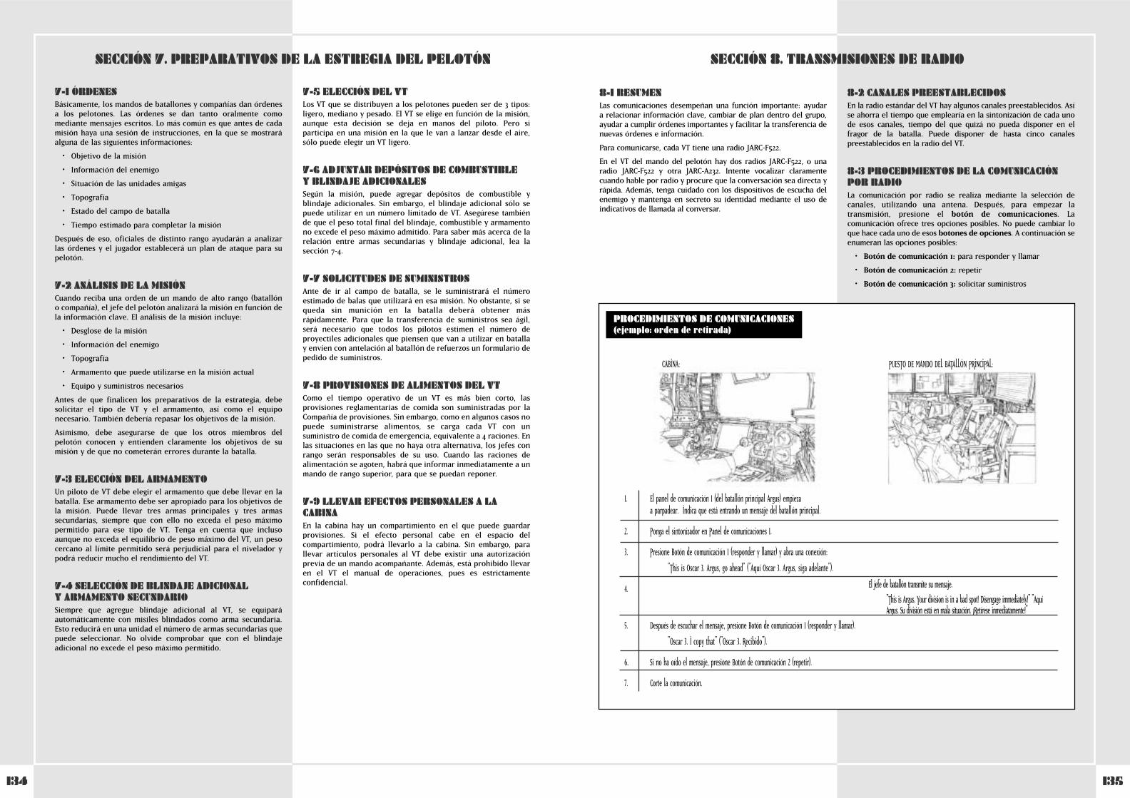
135134
SECCIÓN 8. TRANSMISIONES DE RADIO
1. Communication panel 1 (from the main battalion Argus) begins to flash. Thissignals that a message from the main battalion is coming in.
2. Set the tuner on Communications Panel 1.
3. Press Communication Button 1 (respond/call) and open a connection.
"This is Oscar 3. Argus, go ahead."
El jefe de batallón transmite su mensaje.
"This is Argus. Your division is in a bad spot! Disengage immediately!" "AquíArgus. Su división está en mala situación. ¡Retírese inmediatamente!"
5. After you hear what was said, press Communication Button 1 (respond/call).
"Oscar 3. I copy that."
6. Finish the communication.
7. If you didn’t hear the message, press Communication Button 2 (repeat).
PROCEDIMIENTOS DE COMUNICACIONES(ejemplo: orden de retirada)
CABINA: PUESTO DE MANDO DEL BATALLÓN PRINCIPAL:
1. Communication panel 1 (from the main battalion Argus) begins to flash.This signals that a message from the main battalion is coming in.
2. Set the tuner on Communications Panel 1.
3. Press Communication Button 1 (respond/call) and open a connection.
"This is Oscar 3. Argus, go ahead."
4. The battalion head gives his message.
"This is Argus. Your division is in a bad spot! Retreat immediately!"
5. After you hear what was said, press Communication Button 1 "
6. If you didn’t hear the message, press Communication Button 2 (repeat).
7. Finish the communication.
El panel de comunicación 1 (del batallón principal Argus) empieza a parpadear. Indica que está entrando un mensaje del batallón principal.
Ponga el sintonizador en Panel de comunicaciones 1.
Presione Botón de comunicación 1 (responder y llamar) y abra una conexión:
"This is Oscar 3. Argus, go ahead" ("Aquí Oscar 3. Argus, siga adelante").
4. The battalion head gives his message.
"This is Argus. Your division is in a bad spot! Retreat immediately!"
Después de escuchar el mensaje, presione Botón de comunicación 1 (responder y llamar).
"Oscar 3. I copy that" ("Oscar 3. Recibido").
Si no ha oído el mensaje, presione Botón de comunicación 2 (repetir).
Corte la comunicación.
8-1 RESUMENLas comunicaciones desempeñan una función importante: ayudar a relacionar información clave, cambiar de plan dentro del grupo,ayudar a cumplir órdenes importantes y facilitar la transferencia denuevas órdenes e información.
Para comunicarse, cada VT tiene una radio JARC-F522.
En el VT del mando del pelotón hay dos radios JARC-F522, o unaradio JARC-F522 y otra JARC-A232. Intente vocalizar claramentecuando hable por radio y procure que la conversación sea directa yrápida. Además, tenga cuidado con los dispositivos de escucha delenemigo y mantenga en secreto su identidad mediante el uso deindicativos de llamada al conversar.
8-2 CANALES PREESTABLECIDOSEn la radio estándar del VT hay algunos canales preestablecidos. Asíse ahorra el tiempo que emplearía en la sintonización de cada unode esos canales, tiempo del que quizá no pueda disponer en elfragor de la batalla. Puede disponer de hasta cinco canalespreestablecidos en la radio del VT.
8-3 PROCEDIMIENTOS DE LA COMUNICACIÓNPOR RADIOLa comunicación por radio se realiza mediante la selección decanales, utilizando una antena. Después, para empezar latransmisión, presione el botón de comunicaciones. Lacomunicación ofrece tres opciones posibles. No puede cambiar loque hace cada uno de esos botones de opciones. A continuación seenumeran las opciones posibles:
• Botón de comunicación 1: para responder y llamar
• Botón de comunicación 2: repetir
• Botón de comunicación 3: solicitar suministros
7-1 ÓRDENESBásicamente, los mandos de batallones y compañías dan órdenes a los pelotones. Las órdenes se dan tanto oralmente comomediante mensajes escritos. Lo más común es que antes de cadamisión haya una sesión de instrucciones, en la que se mostraráalguna de las siguientes informaciones:
• Objetivo de la misión
• Información del enemigo
• Situación de las unidades amigas
• Topografía
• Estado del campo de batalla
• Tiempo estimado para completar la misión
Después de eso, oficiales de distinto rango ayudarán a analizarlas órdenes y el jugador establecerá un plan de ataque para supelotón.
7-2 ANÁLISIS DE LA MISIÓNCuando reciba una orden de un mando de alto rango (batallón o compañía), el jefe del pelotón analizará la misión en función dela información clave. El análisis de la misión incluye:
• Desglose de la misión
• Información del enemigo
• Topografía
• Armamento que puede utilizarse en la misión actual
• Equipo y suministros necesarios
Antes de que finalicen los preparativos de la estrategia, debesolicitar el tipo de VT y el armamento, así como el equiponecesario. También debería repasar los objetivos de la misión.
Asimismo, debe asegurarse de que los otros miembros delpelotón conocen y entienden claramente los objetivos de sumisión y de que no cometerán errores durante la batalla.
7-3 ELECCIÓN DEL ARMAMENTOUn piloto de VT debe elegir el armamento que debe llevar en labatalla. Ese armamento debe ser apropiado para los objetivos dela misión. Puede llevar tres armas principales y tres armassecundarias, siempre que con ello no exceda el peso máximopermitido para ese tipo de VT. Tenga en cuenta que inclusoaunque no exceda el equilibrio de peso máximo del VT, un pesocercano al límite permitido será perjudicial para el nivelador ypodrá reducir mucho el rendimiento del VT.
7-4 SELECCIÓN DE BLINDAJE ADICIONAL Y ARMAMENTO SECUNDARIOSiempre que agregue blindaje adicional al VT, se equiparáautomáticamente con misiles blindados como arma secundaria.Esto reducirá en una unidad el número de armas secundarias quepuede seleccionar. No olvide comprobar que con el blindajeadicional no excede el peso máximo permitido.
7-5 ELECCIÓN DEL VTLos VT que se distribuyen a los pelotones pueden ser de 3 tipos:ligero, mediano y pesado. El VT se elige en función de la misión,aunque esta decisión se deja en manos del piloto. Pero siparticipa en una misión en la que le van a lanzar desde el aire,sólo puede elegir un VT ligero.
7-6 ADJUNTAR DEPÓSITOS DE COMBUSTIBLE Y BLINDAJE ADICIONALESSegún la misión, puede agregar depósitos de combustible yblindaje adicionales. Sin embargo, el blindaje adicional sólo sepuede utilizar en un número limitado de VT. Asegúrese tambiénde que el peso total final del blindaje, combustible y armamentono excede el peso máximo admitido. Para saber más acerca de larelación entre armas secundarias y blindaje adicional, lea lasección 7-4.
7-7 SOLICITUDES DE SUMINISTROSAnte de ir al campo de batalla, se le suministrará el númeroestimado de balas que utilizará en esa misión. No obstante, si sequeda sin munición en la batalla deberá obtener másrápidamente. Para que la transferencia de suministros sea ágil,será necesario que todos los pilotos estimen el número deproyectiles adicionales que piensen que van a utilizar en batallay envíen con antelación al batallón de refuerzos un formulario depedido de suministros.
7-8 PROVISIONES DE ALIMENTOS DEL VTComo el tiempo operativo de un VT es más bien corto, lasprovisiones reglamentarias de comida son suministradas por laCompañía de provisiones. Sin embargo, como en algunos casos nopuede suministrarse alimentos, se carga cada VT con unsuministro de comida de emergencia, equivalente a 4 raciones. Enlas situaciones en las que no haya otra alternativa, los jefes conrango serán responsables de su uso. Cuando las raciones dealimentación se agoten, habrá que informar inmediatamente a unmando de rango superior, para que se puedan reponer.
7-9 LLEVAR EFECTOS PERSONALES A LACABINAEn la cabina hay un compartimiento en el que puede guardarprovisiones. Si el efecto personal cabe en el espacio delcompartimiento, podrá llevarlo a la cabina. Sin embargo, parallevar artículos personales al VT debe existir una autorizaciónprevia de un mando acompañante. Además, está prohibido llevaren el VT el manual de operaciones, pues es estrictamenteconfidencial.
SECCIÓN 7. PREPARATIVOS DE LA ESTREGIA DEL PELOTÓN
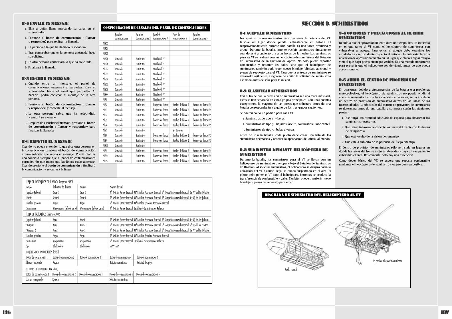
137136
9-1 ACEPTAR SUMINISTROSLos suministros son necesarios para mantener la potencia del VT.Busque un lugar donde pueda reabastecerse en batalla. Elreaprovisionamiento durante una batalla es una tarea ordinaria yardua. Durante la batalla, intente recibir suministros únicamentecuando esté a cubierto o a altas horas de la noche. Los suministrospara los VT se realizan con un helicóptero de suministros del Batallónde Suministros de la División de Apoyo. No sólo puede repostarcombustible y reponer las balas, sino que el helicóptero desuministros también pude traer nuevo blindaje, blindaje adicional ypiezas de repuesto para el VT. Para que la entrega de suministros sedesarrolle ágilmente, asegúrese de emitir la solicitud de suministrosestimada antes de salir para la misión.
9-2 CLASIFICAR SUMINISTROSCon el fin de que la provisión de suministros sea una tarea más fácil,éstos se han separado en cinco grupos principales. Con unas cuantasexcepciones, la mayoría de las piezas que solicitará antes de unabatalla corresponderán a alguno de los tres grupos siguientes..
Se emiten como un pedido para cada VT.
1. Suministros de tipo 1: víveres
2. Suministros de tipo 3: líquidos (aceite, combustible, lubricante)
3. Suministros de tipo 5: balas diversas
Antes de ir a la batalla, cada piloto debe crear una lista de lossuministros necesarios y obtener la aprobación del oficial al mando.
9-3 SUMINISTRO MEDIANTE HELICÓPTERO DESUMINISTROSDurante la batalla, los suministros para el VT se llevan con unhelicóptero de suministros que opera bajo el Batallón de Suministrosde División. Al solicitar suministros, el helicóptero se dirigirá hacia laubicación del VT. Cuando llega, se queda suspendido en el aire. Elpiloto debe poner el VT bajo el helicóptero. Entonces se produce latransferencia de combustible y balas. También puede transferir nuevoblindaje y piezas de repuesto para el VT.
9-4 OPCIONES Y PRECAUCIONES AL RECIBIRSUMINISTROSDebido a que el aprovisionamiento dura un tiempo, hay un intervaloen el que tanto el VT como el helicóptero de suministros sonvulnerables al ataque. Para evitar el ataque debe examinar losalrededores y ser prudente respecto al entorno. Intente establecer laubicación de aprovisionamiento en un lugar que ofrezca algún refugioy en el que haya pocos enemigos visibles. Es una medida importantepara prevenir que el helicóptero sea derribado antes de que puedaaprovisionarle.
9-5 ABRIR EL CENTRO DE PROVISIÓN DESUMINISTROSEn ocasiones, debido a circunstancias de la batalla o a problemasmeteorológicos, el helicóptero de suministros no puede acudir alaprovisionamiento. Para solucionar esas situaciones, se ha instaladoun centro de provisión de suministros detrás de las líneas de lasfuerzas aliadas. La ubicación del centro de provisión de suministrosse determina antes de una batalla y se instala según las siguientespautas:
1. Que tenga una cantidad adecuada de espacio para almacenar lossuministros necesarios.
2. Que una ruta favorable conecte las líneas del frente con las líneasde retaguardia.
3. Que esté oculto de la visión del enemigo.
4. Que esté a cubierto de la potencia de fuego enemiga.
El Centro de provisión de suministros sólo se instala en lugares endonde las líneas del frente estén establecidas y haya un campamentocubriendo el área. Básicamente, sólo hay una excepción.
Como deber básico del VT, se espera que reposte combustiblemediante el helicóptero de suministro siempre que sea posible.
SECCIÓN 9. SUMINISTROS
DIAGRAMA DE SUMINISTRO DEL HELICÓPTERO AL VT
Vuelo normal
Es posible el aprovisionamiento
8-4 ENVIAR UN MENSAJE1. Elija a quién llama marcando su canal en el
sintonizador.
2. Presione el botón de comunicación 1 (llamar y responder) para realizar la llamada.
3. La persona a la que ha llamado responderá.
4. Tras comprobar que es la persona adecuada, hagasu solicitud.
5. La otra persona confirmará lo que ha solicitado.
6. Finalizará la llamada.
8-5 RECIBIR UN MENSAJE1. Cuando entre un mensaje, el panel de
comunicaciones empezará a parpadear. Gire elsintonizador hacia el canal que parpadea. Alhacerlo, podrá escuchar el mensaje de la otrapersona.
2. Presione el botón de comunicación 1 (llamar y responder) y conteste al mensaje.
3. La otra persona sabrá que ha respondido y emitirá su mensaje.
4. Después de escuchar el mensaje, presione el botónde comunicación 1 (llamar y responder) parafinalizar la llamada.
8-6 REPETIR EL MENSAJECuando no pueda entender lo que dice otra persona enla comunicación, presione el botón de comunicación 2 para solicitar que repita el mensaje. Puede realizaruna solicitud siempre que el panel de comunicacionesparpadee (lo que indica que las líneas están abiertas).Cuando presione el botón de comunicación 1, finalizarála comunicación y se cerrará la línea.
CONFIGURACIÓN DE CANALES DEL PANEL DE COMUNICACIONES
Panel de Panel de Panel de Panel de Panel decomunicaciones 1 comunicaciones 2 comunicaciones 3 comunicaciones 4 comunicaciones 5
MIS00
MIS01
MIS02
MIS03 Comando Suministros Mando del VT
MIS04 Comando Suministros Mando del VT
MIS05 Comando Suministros Mando del VT
MIS06 Comando Suministros Mando del VT
MIS07 Comando Suministros Mando del VT
MIS08 Comando Suministros Mando del VT
MIS09 Comando Suministros Mando del VT
MIS10 Comando Suministros Mando del VT
MIS11 Comando Suministros Mando del VT
MIS12 Comando Suministros Hombre de flanco 1 Hombre de flanco 2 Hombre de flanco 1/2
MIS13 Comando Suministros Hombre de flanco 1 Hombre de flanco 2 Hombre de flanco 1/2
MIS14 Comando Suministros Hombre de flanco 1 Hombre de flanco 2 Hombre de flanco 1/2
MIS15 Comando Suministros Hombre de flanco 1 Hombre de flanco 2 Hombre de flanco 1/2
MIS16 Comando Suministros Hombre de flanco 1 Hombre de flanco 2 Hombre de flanco 1/2
MIS17 Comando Suministros Spy Division
MIS18 Comando Suministros Hombre de flanco 1 Hombre de flanco 2 Hombre de flanco 1/2
MIS19 Comando Suministros Hombre de flanco 1 Hombre de flanco 2 Hombre de flanco 1/2
MIS20 Comando Suministros
MIS21 Comando Suministros Hombre de flanco 1 Hombre de flanco 2 Hombre de flanco 1/2
MIS22 Comando Suministros Hombre de flanco 1 Hombre de flanco 2 Hombre de flanco 1/2
MIS23 Comando Suministros Hombre de flanco 1 Hombre de flanco 2 Hombre de flanco 1/2
LISTA DE INDICATIVOS DE LLAMADA (impreso 2080)Grupo Indicativo de llamada Nombre Nombre formal
Jugador (Pelotón) Oscar 3 Oscar 3 7aª División Panzer Especial, 34oº Batallón Acorazado Especial, 6ªaª Compañía Acorazada Especial, 3er VT del 1er Pelotón
Mando Oscar 1 Oscar 1 7ªaª División Panzer Especial, 34ºo Batallón Acorazado Especial, 6ªaª Compañía Acorazada Especial, 1er VT del 1er Pelotón
Batallón principal Argus Argus 7ªaª División Panzer Especial, 34oº Batallón Principal Acorazado Especial
Suministros Wagonmaster (Jefe de carro) Wagonmaster (Jefe de carro) 7ªaª División Panzer Especial, Batallón de Suministros de Refuerzo
LISTA DE INDICATIVOS (impreso 2082)Jugador (Pelotón) Xray 1 Xray 1 7aª División Panzer Especial, 34o Batallón Acorazado Especial, 6aª Compañía Acorazada Especial, 1er VT del 1er Pelotón
Wingman 1 Xray 2 Xray 2 7ªa División Panzer Especial, 34ºo Batallón Acorazado Especial, 6aª Compañía Acorazada Especial, 2ºoº VT del 1er Pelotón
Wingman 2 Xray 3 Xray 3 7aª División Panzer Especial, 34ºo Batallón Acorazado Especial, 6aª Compañía Acorazada Especial, 3er VT del 1er Pelotón
Batallón principal Argus Argus 7aª División Panzer Especial, 34ºo Batallón Principal Acorazado Especial
Suministros Wagonmaster Wagonmaster 7aª División Panzer Especial, Batallón de Suministros de RefuerzoSpy Blackwidow Blackwidow ??????????
BOTONES DE COMUNICACIÓN (2082)Botón de comunicación 1 Botón de comunicación 2 Botón de comunicación 3 Botón de comunicación 4 Botón de comunicación 5Llamar y responder Repetir Solicitar suministros
BOTONES DE COMUNICACIÓN (2080)Botón de comunicación 1 Botón de comunicación 2 Botón de comunicación 3 Botón de comunicación 4 Botón de comunicación 5Llamar y responder Repetir Solicitar suministros Solicitud de apoyo

139138
10-1 DEBERES DEL LIDERAZGOEl deber de un mando es dar órdenes a sus tropas y cumplir lamisión designada. Los mandos se ganan la confianza de sustropas con un liderazgo sólido y manteniendo una divisiónestable y fuerte. De este modo, puede incrementar su experiencia y habilidad con el VT.
10-2 CUALIDADES NECESARIAS PARA EL MANDOUn mando tiene la responsabilidad de llevar a cabo su misión yes además responsable de sus tropas. Debe conocer bien a sushombres, equipo, táctica y estrategia, además de ser un excelentepiloto de VT. Sin embargo, la principal responsabilidad de unmando es ganarse la confianza de sus soldados, proporcionralesun modelo a imitar y avanzar en su misión. Debe trabajar parasalir de la situaciones difíciles. En batalla debe mantener uncriterio claro y tenaz. Debe ser rápido y decidido. Si el mandovacila en la batalla, sus tropas tendrán miedo y perderán laconfianza. Debido a eso, debe analizar cuidadosamente la misiónque se le ha asignado y tener capacidad de establecer planes porsí mismo.
10-3 ÓRDENES DURANTE LA BATALLAEl mando del pelotón debe conseguir que cada integrante de sustropas entienda sus obligaciones, su trabajo y las reglas decombate. Debe mandar sus tropas para sacar lo mejor de ellas.Sobre estas bases, puede dar órdenes simples, para que lasestrategias de la batalla sean más simples de llevar a cabo. Elmando del pelotón debe comunicar sus órdenes con el botón decomunicaciones 4 ó 5 preestablecido, de acuerdo con lasnormas. De esta manera se facilita la comunicación. Hay cuatroórdenes diferentes que se pueden preestablecer. En función delplan de batalla, el mando del pelotón debe elegir dos de esasórdenes.
A continuación se enumeran las cuatro órdenes principales (delas que el mando del pelotón debe elegir dos):
1. Separarse y retirarse
Es una orden para separarse del combate. En caso de queuno de los VT del pelotón sea dañado, el pelotón debeintentar retirarse lo antes posible. El mando del pelotóntiene la responsabilidad de cumplir sus órdenes, peroprotegiendo a sus hombres. Debe hacer todo lo posible pormantener vivos a sus hombres.
2. Apoyo
La tropa del pelotón debe utilizar su VT para apoyar a otratropa, por ejemplo cuando se coopera con otras fuerzas,cuando se ha entrado en contacto con el enemigo, etc. Sehace así para aumentar al máximo la potencia de ataque delpelotón. El mando del pelotón conoce a fondo las reglas y normas y las ha utilizado en prácticas y en el ejercicio realdel mando. También debe elevar el nivel de adiestramientode sus tropas.
3. Ataque
Es una orden para atacar el objetivo principal. El mando delpelotón da esta orden en función de las circunstancias. Aeste respecto, la característica más importante es ser unmodelo a imitar para las tropas, pero alcanzar el objetivo esla meta principal del batallón completo. Cuando hay variosobjetivos, dar esta orden facilitará el cumplimiento de lamisión.
4. Dispersarse
Siempre que crea que llega el enemigo, puede dar a sustropas la orden de dispersión. Esta orden puede ser muy útilcuando la topografía del campo de batalla lo haga necesarioo cuando deba buscar áreas grandes.
WHEN USING THE PLASMA TORCH
10-1 DEBERES DEL LIDERAZGO
ORDEN PARA PELOTÓN: SEPARARSE Y RETIRARSE
ORDEN PARA PELOTÓN: APOYO
ORDEN PARA PELOTÓN: ATACAR ORDEN PARA PELOTÓN: DISPERSARSE
Hombre de flanco 1
Hombre de flanco 2Mando del pelotón
Hombre de flanco 1
Hombre de flanco 2
Mando del pelotón
Hombre de flanco 1
Hombre de flanco 2Mando del pelotón
Hombre de flanco 1
Hombre de flanco 2
Mando del pelotón
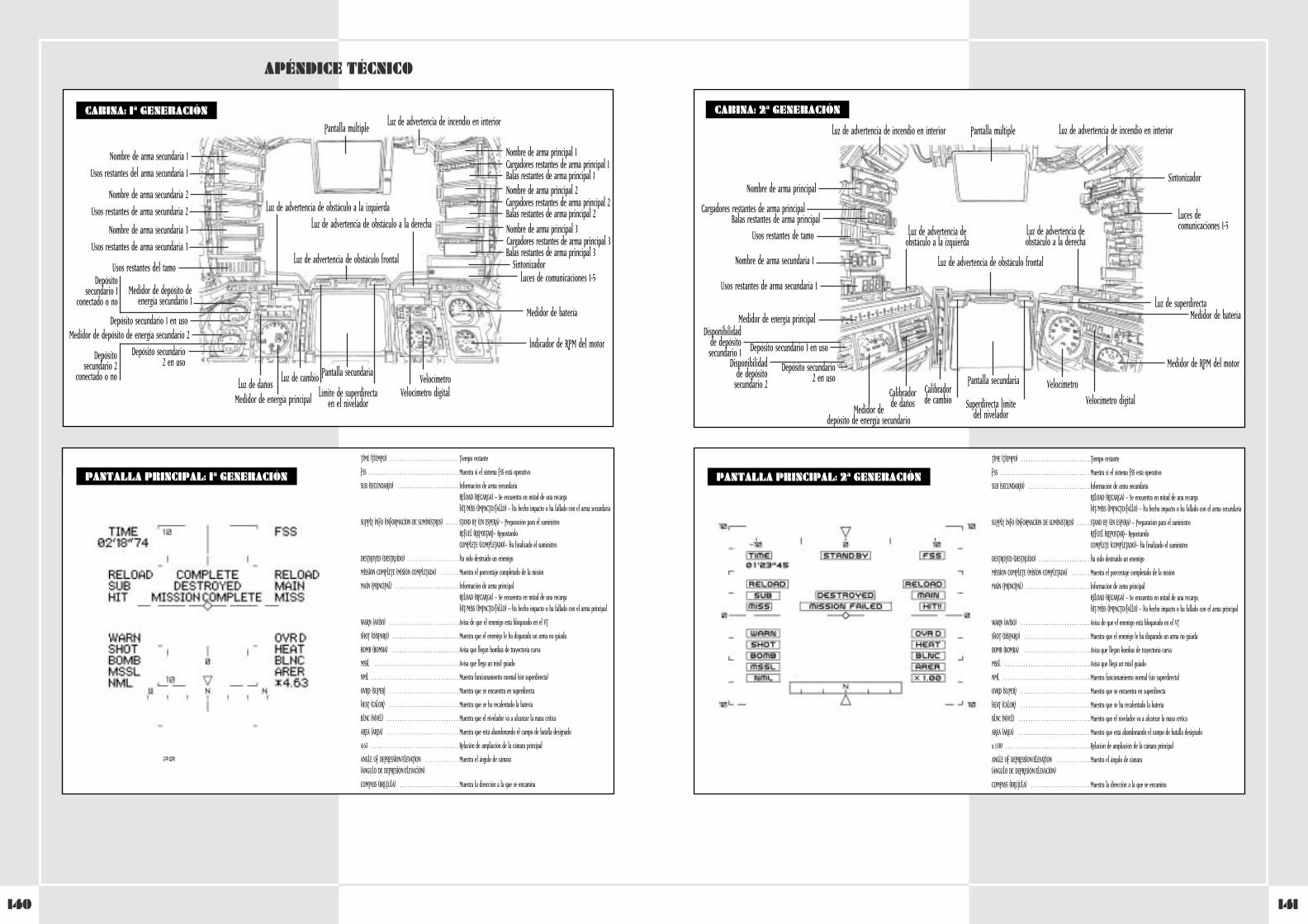
141140
WHEN USING THE PLASMA TORCH
APÉNDICE TÉCNICO
CABINA: 1ª GENERACIÓN
Luz de advertencia de obstáculo frontal
Pantalla múltiple
Nombre de arma secundaria 1
Usos restantes del arma secundaria 1
Nombre de arma principal 1Cargadores restantes de arma principal 1Balas restantes de arma principal 1
Luz de advertencia de incendio en interior
Luz de advertencia de obstáculo a la derecha
Luz de advertencia de obstáculo a la izquierda
Nombre de arma principal 2Cargadores restantes de arma principal 2Balas restantes de arma principal 2Nombre de arma principal 3Cargadores restantes de arma principal 3Balas restantes de arma principal 3
Luces de comunicaciones 1-5
Medidor de batería
Indicador de RPM del motor
Velocímetro
Medidor de energía principalLuz de daños
Pantalla secundariaLuz de cambioVelocímetro digitalLímite de superdirecta
en el nivelador
Sintonizador
Nombre de arma secundaria 2
Usos restantes de arma secundaria 2
Medidor de depósito deenergía secundario 1
Depósitosecundario 1
conectado o no
Depósito secundario 1 en usoMedidor de depósito de energía secundario 2
Depósitosecundario 2
conectado o no
Depósito secundario2 en uso
Nombre de arma secundaria 3
Usos restantes de arma secundaria 3
Usos restantes del tamo
WHEN USING THE PLASMA TORCHCABINA: 2ª GENERACIÓN
Luz de advertencia de obstáculo frontal
Superdirecta límite del nivelador
Pantalla múltiple
Nombre de arma principal
Cargadores restantes de arma principalBalas restantes de arma principal
Luz de advertencia de incendio en interior Luz de advertencia de incendio en interior
Luz de advertencia de obstáculo a la derecha
Luz de advertencia de obstáculo a la izquierda
Luces de comunicaciones 1-5
Medidor de bateríaLuz de superdirecta
Medidor de RPM del motor
Velocímetro
Medidor de energía principal
Pantalla secundariaCalibrador de cambio Velocímetro digital
Sintonizador
Nombre de arma secundaria 1
Usos restantes de arma secundaria 1
Medidor de depósito de energía secundario
Depósito secundario 1 en usoDisponibilidad
de depósitosecundario 1
Depósito secundario2 en uso
Disponibilidadde depósito
secundario 2
Usos restantes de tamo
PANTALLA PRINCIPAL: 2ª GENERACIÓN
TIME (TIEMPO) . . . . . . . . . . . . . . . . . . . . . . . . . . . Tiempo restante
FSS . . . . . . . . . . . . . . . . . . . . . . . . . . . . . . . . . . . Muestra si el sistema FSS está operativo
SUB (SECUNDARIO) . . . . . . . . . . . . . . . . . . . . . . . . Información de arma secundariaRELOAD (RECARGA) – Se encuentra en mitad de una recargaHIT/MISS (IMPACTO/FALLO) – Ha hecho impacto o ha fallado con el arma secundaria
SUPPLY INFO (INFORMACIÓN DE SUMINISTROS) . . . . . STAND BY (EN ESPERA) – Preparación para el suministroREFUEL (REPOSTAR)– RepostandoCOMPLETE (COMPLETADO)– Ha finalizado el suministro
DESTROYED (DESTRUIDO) . . . . . . . . . . . . . . . . . . . . Ha sido destruido un enemigo
MISSION COMPLETE (MISIÓN COMPLETADA) . . . . . . . Muestra el porcentaje completado de la misión
MAIN (PRINCIPAL) . . . . . . . . . . . . . . . . . . . . . . . . . Información de arma principalRELOAD (RECARGA) – Se encuentra en mitad de una recargaHIT/MISS (IMPACTO/FALLO) – Ha hecho impacto o ha fallado con el arma principal
WARN (AVISO) . . . . . . . . . . . . . . . . . . . . . . . . . . . Avisa de que el enemigo está bloqueado en el VT
SHOT (DISPARO) . . . . . . . . . . . . . . . . . . . . . . . . . . Muestra que el enemigo le ha disparado un arma no guiada
BOMB (BOMBA) . . . . . . . . . . . . . . . . . . . . . . . . . . Avisa que llegan bombas de trayectoria curva
MSSL . . . . . . . . . . . . . . . . . . . . . . . . . . . . . . . . . Avisa que llega un misil guiado
NML . . . . . . . . . . . . . . . . . . . . . . . . . . . . . . . . . . Muestra funcionamiento normal (sin superdirecta)
OVRD (SUPER) . . . . . . . . . . . . . . . . . . . . . . . . . . . Muestra que se encuentra en superdirecta
HEAT (CALOR) . . . . . . . . . . . . . . . . . . . . . . . . . . . Muestra que se ha recalentado la batería
BLNC (NIVEL) . . . . . . . . . . . . . . . . . . . . . . . . . . . . Muestra que el nivelador va a alcanzar la masa crítica
AREA (ÁREA) . . . . . . . . . . . . . . . . . . . . . . . . . . . . Muestra que está abandonando el campo de batalla designado
x 1.00 . . . . . . . . . . . . . . . . . . . . . . . . . . . . . . . . . Relación de ampliación de la cámara principal
ANGLE OF DEPRESSION/ELEVATION . . . . . . . . . . . . . Muestra el ángulo de cámara(ÁNGULO DE DEPRESIÓN/ELEVACIÓN)
COMPASS (BRÚJULA) . . . . . . . . . . . . . . . . . . . . . . . Muestra la dirección a la que se encamina
PANTALLA PRINCIPAL: 1ª GENERACIÓN
TIME (TIEMPO) . . . . . . . . . . . . . . . . . . . . . . . . . . . Tiempo restante
FSS . . . . . . . . . . . . . . . . . . . . . . . . . . . . . . . . . . . Muestra si el sistema FSS está operativo
SUB (SECUNDARIO) . . . . . . . . . . . . . . . . . . . . . . . . Información de arma secundariaRELOAD (RECARGA) – Se encuentra en mitad de una recargaHIT/MISS (IMPACTO/FALLO) – Ha hecho impacto o ha fallado con el arma secundaria
SUPPLY INFO (INFORMACIÓN DE SUMINISTROS) . . . . . STAND BY (EN ESPERA) – Preparación para el suministroREFUEL (REPOSTAR)– RepostandoCOMPLETE (COMPLETADO)– Ha finalizado el suministro
DESTROYED (DESTRUIDO) . . . . . . . . . . . . . . . . . . . . Ha sido destruido un enemigo
MISSION COMPLETE (MISIÓN COMPLETADA) . . . . . . . Muestra el porcentaje completado de la misión
MAIN (PRINCIPAL) . . . . . . . . . . . . . . . . . . . . . . . . . Información de arma principalRELOAD (RECARGA) – Se encuentra en mitad de una recargaHIT/MISS (IMPACTO/FALLO) – Ha hecho impacto o ha fallado con el arma principal
WARN (AVISO) . . . . . . . . . . . . . . . . . . . . . . . . . . . Avisa de que el enemigo está bloqueado en el VT
SHOT (DISPARO) . . . . . . . . . . . . . . . . . . . . . . . . . . Muestra que el enemigo le ha disparado un arma no guiada
BOMB (BOMBA) . . . . . . . . . . . . . . . . . . . . . . . . . . Avisa que llegan bombas de trayectoria curva
MSSL . . . . . . . . . . . . . . . . . . . . . . . . . . . . . . . . . Avisa que llega un misil guiado
NML . . . . . . . . . . . . . . . . . . . . . . . . . . . . . . . . . . Muestra funcionamiento normal (sin superdirecta)
OVRD (SUPER) . . . . . . . . . . . . . . . . . . . . . . . . . . . Muestra que se encuentra en superdirecta
HEAT (CALOR) . . . . . . . . . . . . . . . . . . . . . . . . . . . Muestra que se ha recalentado la batería
BLNC (NIVEL) . . . . . . . . . . . . . . . . . . . . . . . . . . . . Muestra que el nivelador va a alcanzar la masa crítica
AREA (ÁREA) . . . . . . . . . . . . . . . . . . . . . . . . . . . . Muestra que está abandonando el campo de batalla designado
4.63 . . . . . . . . . . . . . . . . . . . . . . . . . . . . . . . . . . Relación de ampliación de la cámara principal
ANGLE OF DEPRESSION/ELEVATION . . . . . . . . . . . . . Muestra el ángulo de cámara(ÁNGULO DE DEPRESIÓN/ELEVACIÓN)
COMPASS (BRÚJULA) . . . . . . . . . . . . . . . . . . . . . . . Muestra la dirección a la que se encamina
Calibrador de daños
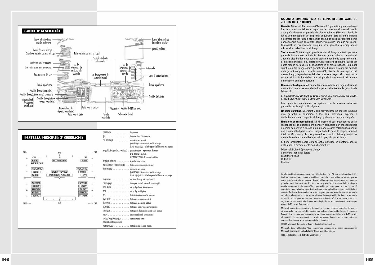
143142
GARANTÍA LIMITADA PARA SU COPIA DEL SOFTWARE DEJUEGOS XBOX (“JUEGO”) Garantía. Microsoft Corporation (“Microsoft”) garantiza que este Juegofuncionará sustancialmente según se describe en el manual que loacompaña durante un período de ciento ochenta (180) días desde lafecha de su recepción por su primer adquirente. Esta garantía limitadano comprende los fallos o problemas del Juego que se produzcan comoconsecuencia de un accidente, abuso, virus o uso indebido del Juego.Microsoft no proporciona ninguna otra garantía o compromisoadicional en relación con el Juego.Sus recursos. Si tiene algún problema con el Juego cubierto por estagarantía durante este período de ciento ochenta (180) días, devuelva elJuego al distribuidor junto con una copia del recibo de compra original.El distribuidor podrá, a su discreción, (a) reparar o sustituir el Juego sincoste alguno para Vd., o (b) reembolsarle el precio pagado. Cualquiersustitución del Juego estará garantizada durante el resto del períodode la garantía original o durante treinta (30) días desde la recepción delnuevo Juego, dependiendo del plazo que sea mayor. Microsoft no seresponsabiliza de los daños que Vd. podría haber evitado si hubieraempleado el cuidado oportuno.
Otros derechos legales. Vd. puede tener otros derechos legales frente aldistribuidor que no se ven afectados por esta limitación de garantía deMicrosoft.
SI VD. NO HA ADQUIRIDO EL JUEGO PARA USO PERSONAL (ES DECIR,SI NO ESTÁ ACTUANDO COMO CONSUMIDOR)
Las siguientes condiciones se aplican con la máxima extensiónpermitida por la legislación vigente.
No otras garantías. Microsoft y sus proveedores no otorgan ningunaotra garantía o condición a las aquí previstas, expresa oimplícitamente, con respecto al Juego y al manual que lo acompaña.
Limitación de responsabilidad. Ni Microsoft ni sus proveedores seránresponsables de cualesquiera daños y perjuicios con independenciade cómo se deriven o que de alguna manera estén relacionados con eluso o la ineptitud para usar el Juego. En todo caso, la responsabilidadtotal de Microsoft y de sus proveedores por los daños y perjuiciosqueda limitada a la cantidad que Vd. ha pagado por el Juego.
Si tiene preguntas sobre esta garantía, póngase en contacto con sudistribuidor o directamente con Microsoft en:
Microsoft Ireland Operations LimitedSandyford Industrial EstateBlackthorn RoadDublin 18Irlanda
La información de este documento, incluidas la dirección URL y otras referencias al sitioWeb de Internet, está sujeta a modificaciones sin previo aviso. A menos que secomunique lo contrario, los ejemplos de compañías, organizaciones, productos, personasy hechos aquí descritos son ficticios y no se pretende ni se debe deducir ningunaasociación con cualquier compañía, organización, producto, persona o hecho real. Elcumplimiento de todas las leyes de derecho de autor aplicables es responsabilidad delusuario. Sin limitar los derechos de autor, ninguna parte de este documento se puedereproducir, almacenar o utilizar en un sistema de recuperación de datos, ni se puedetransmitir de cualquier forma o por cualquier medio (electrónico, mecánico, fotocopia,registro o de otro modo), ni utilizarse para ningún fin, sin el consentimiento expreso porescrito de Microsoft Corporation.
Microsoft puede tener patentes, solicitudes de patentes, marcas, derechos de autor uotros derechos de propiedad intelectual que cubran el contenido de este documento.Excepto si se concede expresamente por escrito en un acuerdo de licencia de Microsoft,el contenido de este documento no le otorga ninguna licencia sobre estas patentes,marcas, derechos de autor u otra propiedad intelectual.
© 2003 Microsoft Corporation. Reservados todos los derechos.
Microsoft, Xbox y el logotipo Xbox son marcas comerciales o marcas comerciales deMicrosoft Corporation en los Estados Unidos y en otros países.
Fabricado bajo licencia de Dolby Laboratories.
WHEN USING THE PLASMA TORCHCABINA: 3ª GENERACIÓN
Luz de advertencia deobstáculo frontal
Superdirecta límite del nivelador
Pantalla múltipleNombre de arma principalCargadores restantes de arma principal Balas restantes de arma principal
Luz de advertencia de incendio en interior
Luz de advertencia de incendio en interior
Luz de advertencia deobstáculo a la
derecha
Luz de advertencia deobstáculo a la
izquierdaLuces de comunicaciones 1-5
Medidor de batería
Luz de superdirectaLuz de superdirecta
Medidor de RPM del motorVelocímetro
Medidor de energía principal
Calibrador de daños Pantallasecundaria
Calibrador de cambio
Velocímetro digital
Sintonizador
Nombre de arma secundaria 1Usos restantes de arma secundaria 1
Medidor de depósito de energía secundario 1
Disponibilidadde depósitosecundario 1
Medidor de depósito deenergía secundario 2
Disponibilidad dedepósito secundario 2
Usos restantes del tamo
PANTALLA PRINCIPAL: 3ª GENERACIÓN
TIME (TIEMPO) . . . . . . . . . . . . . . . . . . . . . . . . Tiempo restante
FSS . . . . . . . . . . . . . . . . . . . . . . . . . . . . . . . . Muestra si el sistema FSS está operativo
SUB (SECUNDARIO) . . . . . . . . . . . . . . . . . . . . . Información de arma secundariaRELOAD (RECARGA) – Se encuentra en mitad de una recargaHIT/MISS (IMPACTO/FALLO) – Ha hecho impacto o ha fallado con el arma secundaria
SUPPLY INFO (INFORMACIÓN DE SUMINISTROS) . . STAND BY (EN ESPERA) – Preparación para el suministroREFUEL (REPOSTAR)– RepostandoCOMPLETE (COMPLETADO)– Ha finalizado el suministro
DESTROYED (DESTRUIDO) . . . . . . . . . . . . . . . . . Ha sido destruido un enemigo
MISSION COMPLETE (MISIÓN COMPLETADA) . . . . . Muestra el porcentaje completado de la misión
MAIN (PRINCIPAL) . . . . . . . . . . . . . . . . . . . . . . Información de arma principalRELOAD (RECARGA) – Se encuentra en mitad de una recargaHIT/MISS (IMPACTO/FALLO) – Ha hecho impacto o ha fallado con el arma principal
WARN (AVISO) . . . . . . . . . . . . . . . . . . . . . . . . Avisa de que el enemigo está bloqueado en el VT
SHOT (DISPARO) . . . . . . . . . . . . . . . . . . . . . . . Muestra que el enemigo le ha disparado un arma no guiada
BOMB (BOMBA) . . . . . . . . . . . . . . . . . . . . . . . . Avisa que llegan bombas de trayectoria curva
MSSL . . . . . . . . . . . . . . . . . . . . . . . . . . . . . . . Avisa que llega un misil guiado
NML . . . . . . . . . . . . . . . . . . . . . . . . . . . . . . . Muestra funcionamiento normal (sin superdirecta)
OVRD (SUPER) . . . . . . . . . . . . . . . . . . . . . . . . Muestra que se encuentra en superdirecta
HEAT (CALOR) . . . . . . . . . . . . . . . . . . . . . . . . . Muestra que se ha recalentado la batería
BLNC (NIVEL) . . . . . . . . . . . . . . . . . . . . . . . . . Muestra que el nivelador va a alcanzar la masa crítica
AREA (ÁREA) . . . . . . . . . . . . . . . . . . . . . . . . . . Muestra que está abandonando el campo de batalla designado
x 1.00 . . . . . . . . . . . . . . . . . . . . . . . . . . . . . . Relación de ampliación de la cámara principal
ANGLE OF DEPRESSION/ELEVATION . . . . . . . . . . . Muestra el ángulo de cámara(ÁNGULO DE DEPRESIÓN/ELEVACIÓN)
COMPASS (BRÚJULA) . . . . . . . . . . . . . . . . . . . . Muestra la dirección a la que se encamina
145144
INSTALLAZIONE DEL CONTROLLER . . . . . . . . . . . . . . . . . . . . . . . . . . . . . 146
Precauzioni . . . . . . . . . . . . . . . . . . . . . . . . . . . . . . . . . . . . . . . . . 146
Risoluzione dei problemi . . . . . . . . . . . . . . . . . . . . . . . . . . . . . . 146
Montaggio dell'unità destra . . . . . . . . . . . . . . . . . . . . . . . . . . . . . 146
Montaggio dell'unità sinistra . . . . . . . . . . . . . . . . . . . . . . . . . . . . 146
SEZIONE 1. IDEAZIONE DI VT E DIVISIONE SPECIALE PANZER . . . . . . . . . 148
1-1 Ideazione del VT . . . . . . . . . . . . . . . . . . . . . . . . . . . . . . . . . . . 148
1-2 Nozioni di base sull'utilizzo militare del VT . . . . . . . . . . . . . . 148
1-3 Doveri delle unità speciali corazzate . . . . . . . . . . . . . . . . . . . 148
1-4 Formazione di una divisione speciale panzer . . . . . . . . . . . . . 148
1-5 Organizzazione di un plotone di VT . . . . . . . . . . . . . . . . . . . . 148
SEZIONE 2. INTRODUZIONE AI VT . . . . . . . . . . . . . . . . . . . . . . . . . . . . . 149
2-1 Componenti di base di un VT . . . . . . . . . . . . . . . . . . . . . . . . . 149
2-2 Sistema operativo di un VT . . . . . . . . . . . . . . . . . . . . . . . . . . 149
2-3 Tipi di VT . . . . . . . . . . . . . . . . . . . . . . . . . . . . . . . . . . . . . . . . 150
2-4 Spostamento . . . . . . . . . . . . . . . . . . . . . . . . . . . . . . . . . . . . . 150
2-5 Serbatoio di carburante e serbatoi di riserva . . . . . . . . . . . . 150
2-6 Consumo di carburante e tempo di spostamento stimato . . . 150
2-7 Corazza difensiva . . . . . . . . . . . . . . . . . . . . . . . . . . . . . . . . . . 150
2-8 Armi principali e armi secondarie . . . . . . . . . . . . . . . . . . . . . 150
2-9 Peso massimo consentito per le armi . . . . . . . . . . . . . . . . . . 150
2-10 Armi caricate sui VT . . . . . . . . . . . . . . . . . . . . . . . . . . . . . . . 151
2-11 Puntamento delle armi con traiettoria curva sulla mappa da combattimento . . . . . . . . . . . . . . . . . . . . . . . 156
2-12 Spoletta magnetica . . . . . . . . . . . . . . . . . . . . . . . . . . . . . . . . 156
2-13 Difesa antiradar . . . . . . . . . . . . . . . . . . . . . . . . . . . . . . . . . . 156
SEZIONE 3. FUNZIONI SPECIALI
DEI SISTEMI COOS DI SECONDA GENERAZIONE . . . . . . . . . . . . . . . . . . . 156
3-1 Elementi introdotti nei sistemi COOS di seconda generazione . 156
3-2 Funzione FSS . . . . . . . . . . . . . . . . . . . . . . . . . . . . . . . . . . . . . 156
3-3 Funzione di overdrive . . . . . . . . . . . . . . . . . . . . . . . . . . . . . . 156
3-4 Funzione Stealth . . . . . . . . . . . . . . . . . . . . . . . . . . . . . . . . . . 156
3-5 Armi guidate . . . . . . . . . . . . . . . . . . . . . . . . . . . . . . . . . . . . . 156
SEZIONE 4. CONTROLLI DEI VT . . . . . . . . . . . . . . . . . . . . . . . . . . . . . . . 157
4-1 Sequenza di avvio . . . . . . . . . . . . . . . . . . . . . . . . . . . . . . . . . . 157
4-2 Blocco del VT durante l'avvio . . . . . . . . . . . . . . . . . . . . . . . . . 157
Controlli di base . . . . . . . . . . . . . . . . . . . . . . . . . . . . . . . . . . . . . 158
4-3 Spostamento e arresto . . . . . . . . . . . . . . . . . . . . . . . . . . . . . . 158
4-4 Accelerazione e decelerazione . . . . . . . . . . . . . . . . . . . . . . . 158
4-5 Rotazione . . . . . . . . . . . . . . . . . . . . . . . . . . . . . . . . . . . . . . . 158
4-6 Overdrive . . . . . . . . . . . . . . . . . . . . . . . . . . . . . . . . . . . . . . . 158
4-7 Funzione di spostamento rapido . . . . . . . . . . . . . . . . . . . . . . 158
4-8 Limiti funzionali dello spostamento rapido . . . . . . . . . . . . . . 158
4-9 Regolatore dello spostamento rapido . . . . . . . . . . . . . . . . . . 158
4-10 Funzione di spegnimento . . . . . . . . . . . . . . . . . . . . . . . . . . . 158
4-11 Controlli del manipolatore . . . . . . . . . . . . . . . . . . . . . . . . . . 159
Monitor del VT . . . . . . . . . . . . . . . . . . . . . . . . . . . . . . . . . . . . . 160
4-12 Modifica della telecamera principale . . . . . . . . . . . . . . . . . . 160
4-13 Pulizia della telecamera principale . . . . . . . . . . . . . . . . . . . . 160
4-14 Funzioni del monitor secondario . . . . . . . . . . . . . . . . . . . . . 161
4-15 Equipaggiamento per la visione notturna . . . . . . . . . . . . . . . 161
Sistema completo di comando JCS . . . . . . . . . . . . . . . . . . . . . . . . 161
4-16 Introduzione al JCS . . . . . . . . . . . . . . . . . . . . . . . . . . . . . . . . 161
4-17 Display multi-monitor . . . . . . . . . . . . . . . . . . . . . . . . . . . . . . 162
4-18 Informazioni visualizzate nel multi-monitor . . . . . . . . . . . . . 162
Procedure di emergenza . . . . . . . . . . . . . . . . . . . . . . . . . . . . . . . . . . . 163
4-19 Dispositivo di espulsione . . . . . . . . . . . . . . . . . . . . . . . . . . . 163
4-20 Interruttore per l'espulsione di emergenza . . . . . . . . . . . . . 163
4-21 Procedure per l'espulsione di emergenza in acqua . . . . . . . . 163
4-22 Incendio nello scafo . . . . . . . . . . . . . . . . . . . . . . . . . . . . . . 163
SEZIONE 5. ATTACCO A VT . . . . . . . . . . . . . . . . . . . . . . . . . . . . . . . . . . 164
5-1 Puntamento e azionamento delle armi . . . . . . . . . . . . . . . . . . 164
5-2 Funzione di agganciamento . . . . . . . . . . . . . . . . . . . . . . . . . . 164
5-3 Puntamento in combattimento ravvicinato . . . . . . . . . . . . . . 164
5-4 Funzione FSS . . . . . . . . . . . . . . . . . . . . . . . . . . . . . . . . . . . . . 165
5-5 Portata di tiro delle diverse armi . . . . . . . . . . . . . . . . . . . . . . 165
5-6 Note sulla portata di tiro effettiva . . . . . . . . . . . . . . . . . . . . . 165
5-7 Utilizzo della portata di tiro effettiva . . . . . . . . . . . . . . . . . . . 166
5-8 Attacco di neutralizzazione . . . . . . . . . . . . . . . . . . . . . . . . . 166
5-9 Modifica delle armi . . . . . . . . . . . . . . . . . . . . . . . . . . . . . . . . 166
5-10 Ricarica delle armi con caricatore . . . . . . . . . . . . . . . . . . . . 166
SEZIONE 6. SPOSTAMENTO DEL VT . . . . . . . . . . . . . . . . . . . . . . . . . . . . 167
6-1 Informazioni generali . . . . . . . . . . . . . . . . . . . . . . . . . . . . . . 167
6-2 Condizioni atmosferiche e topografia . . . . . . . . . . . . . . . . . . 167
CONFIGURAZIONE DEL CONTROLLER STEEL BATTALION . . . . . . . . . . . . 168
SEZIONE 7. PREPARAZIONE STRATEGICA DEL PLOTONE . . . . . . . . . . . . . 170
7-1 Ordini . . . . . . . . . . . . . . . . . . . . . . . . . . . . . . . . . . . . . . . . . . 170
7-2 Analisi della missione . . . . . . . . . . . . . . . . . . . . . . . . . . . . . . 170
7-3 Scelta delle armi . . . . . . . . . . . . . . . . . . . . . . . . . . . . . . . . . . 170
7-4 Selezione di corazza aggiuntiva e armi secondarie . . . . . . . . . 170
7-5 Scelta del VT . . . . . . . . . . . . . . . . . . . . . . . . . . . . . . . . . . . . . 170
7-6 Aggiunta di corazza e serbatoi di carburante . . . . . . . . . . . . . 170
7-7 Richieste di rifornimenti . . . . . . . . . . . . . . . . . . . . . . . . . . . . 170
7-8 Razioni alimentari del VT . . . . . . . . . . . . . . . . . . . . . . . . . . . 170
7-9 Trasporto di effetti personali nell'abitacolo . . . . . . . . . . . . . 170
SEZIONE 8. TRASMISSIONI RADIO
8-1 Introduzione . . . . . . . . . . . . . . . . . . . . . . . . . . . . . . . . . . . . . . 171
8-2 Canali preimpostati . . . . . . . . . . . . . . . . . . . . . . . . . . . . . . . . 171
8-3 Procedure di comunicazione via radio . . . . . . . . . . . . . . . . . . 171
8-4 Invio di un messaggio . . . . . . . . . . . . . . . . . . . . . . . . . . . . . . 172
8-5 Ricezione di un messaggio . . . . . . . . . . . . . . . . . . . . . . . . . . . 172
8-6 Ripetizione di un messaggio . . . . . . . . . . . . . . . . . . . . . . . . . 172
SEZIONE 9. RIFORNIMENTI . . . . . . . . . . . . . . . . . . . . . . . . . . . . . . . . . . 173
9-1 Ricezione di rifornimenti . . . . . . . . . . . . . . . . . . . . . . . . . . . . 173
9-2 Classificazione dei rifornimenti . . . . . . . . . . . . . . . . . . . . . . . 173
9-3 Rifornimenti tramite elicottero . . . . . . . . . . . . . . . . . . . . . . . 173
9-4 Precauzioni durante la ricezione dei rifornimenti . . . . . . . . . 173
9-5 Creazione di un centro di rifornimento . . . . . . . . . . . . . . . . . 173
SEZIONE 10. COMANDO . . . . . . . . . . . . . . . . . . . . . . . . . . . . . . . . . . . . . 174
10-1 Doveri dei comandanti . . . . . . . . . . . . . . . . . . . . . . . . . . . . . 174
10-2 Qualità necessarie per i comandanti . . . . . . . . . . . . . . . . . . . 174
10-3 Ordini durante il combattimento . . . . . . . . . . . . . . . . . . . . . 174
APPENDICE TECNICA . . . . . . . . . . . . . . . . . . . . . . . . . . . . . . . . . . . . . . 176
Abitacolo: prima generazione . . . . . . . . . . . . . . . . . . . . . . . . . . . 176
Display monitor principale: prima generazione . . . . . . . . . . . . . . 176
Abitacolo: seconda generazione . . . . . . . . . . . . . . . . . . . . . . . . . 177
Display monitor principale: seconda generazione . . . . . . . . . . . . 177
Abitacolo: terza generazione . . . . . . . . . . . . . . . . . . . . . . . . . . . . 178
Display monitor principale: terza generazione . . . . . . . . . . . . . . 178
Garanzia . . . . . . . . . . . . . . . . . . . . . . . . . . . . . . . . . . . . . . . . . . . 179
Supporto tecnico . . . . . . . . . . . . . . . . . . . . . . . . . . . . . . . . . . . . . 181
ITALIANOPRIMA DI UTILIZZARE IL GIOCOGrazie per avere scelto STEEL BATTALION. Prima di utilizzare ilgioco, leggi interamente i manuali di istruzioni. Dopo avereconsultato i manuali, conservali in un luogo sicuro in modo dapoterli utilizzare per riferimento.
ATTENZIONE• Mantieni l'unità e tutti i componenti fuori dalla portata dei
bambini.
• Non aprire o modificare l'unità o i componenti.
• Non versare liquidi sull'unità o sui componenti.
• Conserva l'unità e i componenti in un ambiente asciutto e alriparo dalla polvere.
• In caso di problemi, interrompi immediatamente l'utilizzo.
SOMMARIO
INFORMAZIONI SULLA SICUREZZADisturbi di fotosensibilitàIn una percentuale minima di utenti potrebbero insorgeredisturbi dovuti all'esposizione ad alcune immagini, inclusimotivi o luci intermittenti contenuti nei videogiochi. Anche neisoggetti che in precedenza non hanno mai accusato disturbi difotosensibilità o epilessia potrebbe celarsi una patologia nondiagnosticata in grado di causare attacchi epilettici dovuti allafotosensibilità durante l'utilizzo di videogiochi.
Tali disturbi possono essere accompagnati da vari sintomi,inclusi vertigini, visione alterata, spasmi al volto o agli occhi,spasmi o tremori alle braccia o alle gambe, senso didisorientamento, confusione o perdita temporanea dei sensi. Leconvulsioni o la perdita dei sensi provocate dagli attacchipossono causare conseguenze dovute a cadute o all'impattocontro gli oggetti circostanti.
In presenza di uno qualsiasi di questi sintomi, interrompereimmediatamente l'utilizzo del videogioco e consultare unmedico. Poiché i bambini e gli adolescenti sono più soggetti aquesto tipo di attacchi rispetto agli adulti, i genitori dovrebberoosservare o farsi descrivere direttamente l'eventuale insorgenzadei sintomi sopra indicati.
È possibile ridurre il rischio di attacchi epilettici dovuti allafotosensibilità sedendo lontano dallo schermo del televisore,utilizzando uno schermo di dimensioni limitate, giocando in unastanza ben illuminata ed evitando di utilizzare il gioco quandosi è stanchi o affaticati.
Se nell'ambito familiare si sono verificati in precedenza casi difotosensibilità o epilessia, consultare un medico prima diutilizzare il gioco.
Altre informazioni importanti sulla tutela della salute e sullasicurezza: il Manuale di istruzioni di Xbox contieneinformazioni importanti sulla tutela della salute e sullasicurezza, che è consigliabile leggere attentamente prima diutilizzare questo software.
Come evitare di danneggiare il televisoreNon utilizzare alcuni tipi di televisore. Alcuni tipi ditelevisore, in particolare gli apparecchi a proiezione oretroproiezione possono essere danneggiati dall'uso di qualsiasivideogioco, inclusi i videogiochi di Xbox. Le immagini statichevisualizzate durante il normale svolgimento del giocopotrebbero "fissarsi" sullo schermo causando un'ombrapermanente dell'immagine statica, che permane anche quandonon vengono utilizzati i videogiochi. Un danno analogo puòessere provocato dalle immagini statiche create quando simette in attesa o in pausa un videogioco. Consultare il manualedel televisore per verificare se l'apparecchio consente l'utilizzodi videogiochi. Se tali informazioni non sono disponibili nelsuddetto manuale, contattare il rivenditore o il produttoredell'apparecchio.
La copia non autorizzata, la decodificazione, la trasmissione,l'uso pubblico, il noleggio, il pay per play o l'inosservanza dellaprotezione della copia sono severamente proibiti.
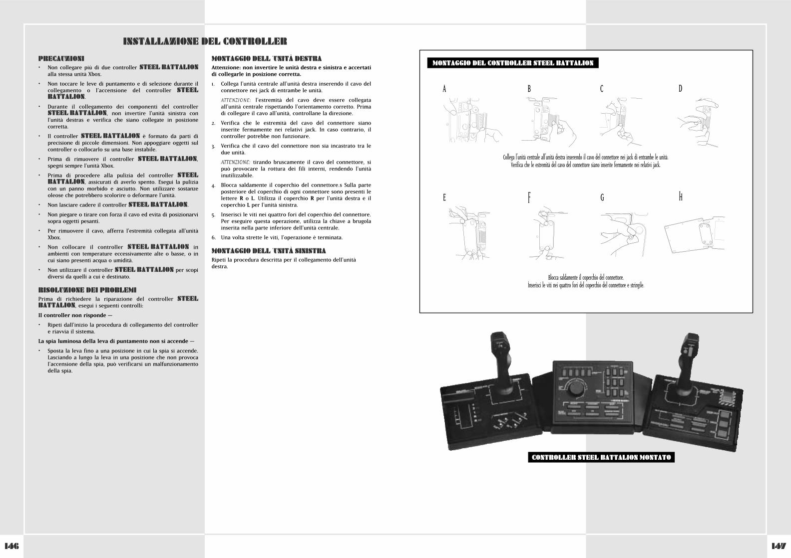
147146
INSTALLAZIONE DEL CONTROLLER
PRECAUZIONI• Non collegare più di due controller STEEL BATTALION
alla stessa unità Xbox.
• Non toccare le leve di puntamento e di selezione durante ilcollegamento o l'accensione del controller STEELBATTALION.
• Durante il collegamento dei componenti del controllerSTEEL BATTALION, non invertire l'unità sinistra conl'unità destras e verifica che siano collegate in posizionecorretta.
• Il controller STEEL BATTALION è formato da parti diprecisione di piccole dimensioni. Non appoggiare oggetti sulcontroller o collocarlo su una base instabile.
• Prima di rimuovere il controller STEEL BATTALION,spegni sempre l'unità Xbox.
• Prima di procedere alla pulizia del controller STEELBATTALION, assicurati di averlo spento. Esegui la puliziacon un panno morbido e asciutto. Non utilizzare sostanzeoleose che potrebbero scolorire o deformare l'unità.
• Non lasciare cadere il controller STEEL BATTALION.
• Non piegare o tirare con forza il cavo ed evita di posizionarvisopra oggetti pesanti.
• Per rimuovere il cavo, afferra l'estremità collegata all'unitàXbox.
• Non collocare il controller STEEL BATTALION inambienti con temperature eccessivamente alte o basse, o incui siano presenti acqua o umidità.
• Non utilizzare il controller STEEL BATTALION per scopidiversi da quelli a cui è destinato.
RISOLUZIONE DEI PROBLEMIPrima di richiedere la riparazione del controller STEELBATTALION, esegui i seguenti controlli:
Il controller non risponde –
• Ripeti dall'inizio la procedura di collegamento del controller e riavvia il sistema.
La spia luminosa della leva di puntamento non si accende –
• Sposta la leva fino a una posizione in cui la spia si accende.Lasciando a lungo la leva in una posizione che non provocal'accensione della spia, può verificarsi un malfunzionamentodella spia.
MONTAGGIO DELL ´UNITÀ DESTRAAttenzione: non invertire le unità destra e sinistra e accertatidi collegarle in posizione corretta.
1. Collega l'unità centrale all'unità destra inserendo il cavo delconnettore nei jack di entrambe le unità.
ATTENZIONE: l'estremità del cavo deve essere collegataall'unità centrale rispettando l'orientamento corretto. Primadi collegare il cavo all'unità, controllane la direzione.
2. Verifica che le estremità del cavo del connettore sianoinserite fermamente nei relativi jack. In caso contrario, ilcontroller potrebbe non funzionare.
3. Verifica che il cavo del connettore non sia incastrato tra ledue unità.
ATTENZIONE: tirando bruscamente il cavo del connettore, sipuò provocare la rottura dei fili interni, rendendo l'unitàinutilizzabile.
4. Blocca saldamente il coperchio del connettore.s Sulla parteposteriore del coperchio di ogni connettore sono presenti lelettere R o L. Utilizza il coperchio R per l'unità destra e ilcoperchio L per l'unità sinistra.
5. Inserisci le viti nei quattro fori del coperchio del connettore.Per eseguire questa operazione, utilizza la chiave a brugolainserita nella parte inferiore dell'unità centrale.
6. Una volta strette le viti, l'operazione è terminata.
MONTAGGIO DELL ´UNITÀ SINISTRARipeti la procedura descritta per il collegamento dell'unitàdestra.
MONTAGGIO DEL CONTROLLER STEEL BATTALION
CONTROLLER STEEL BATTALION MONTATO
Collega l'unità centrale all'unità destra inserendo il cavo del connettore nei jack di entrambe le unità. Verifica che le estremità del cavo del connettore siano inserite fermamente nei relativi jack.
Blocca saldamente il coperchio del connettore.Inserisci le viti nei quattro fori del coperchio del connettore e stringile.
A B C D
E F G H
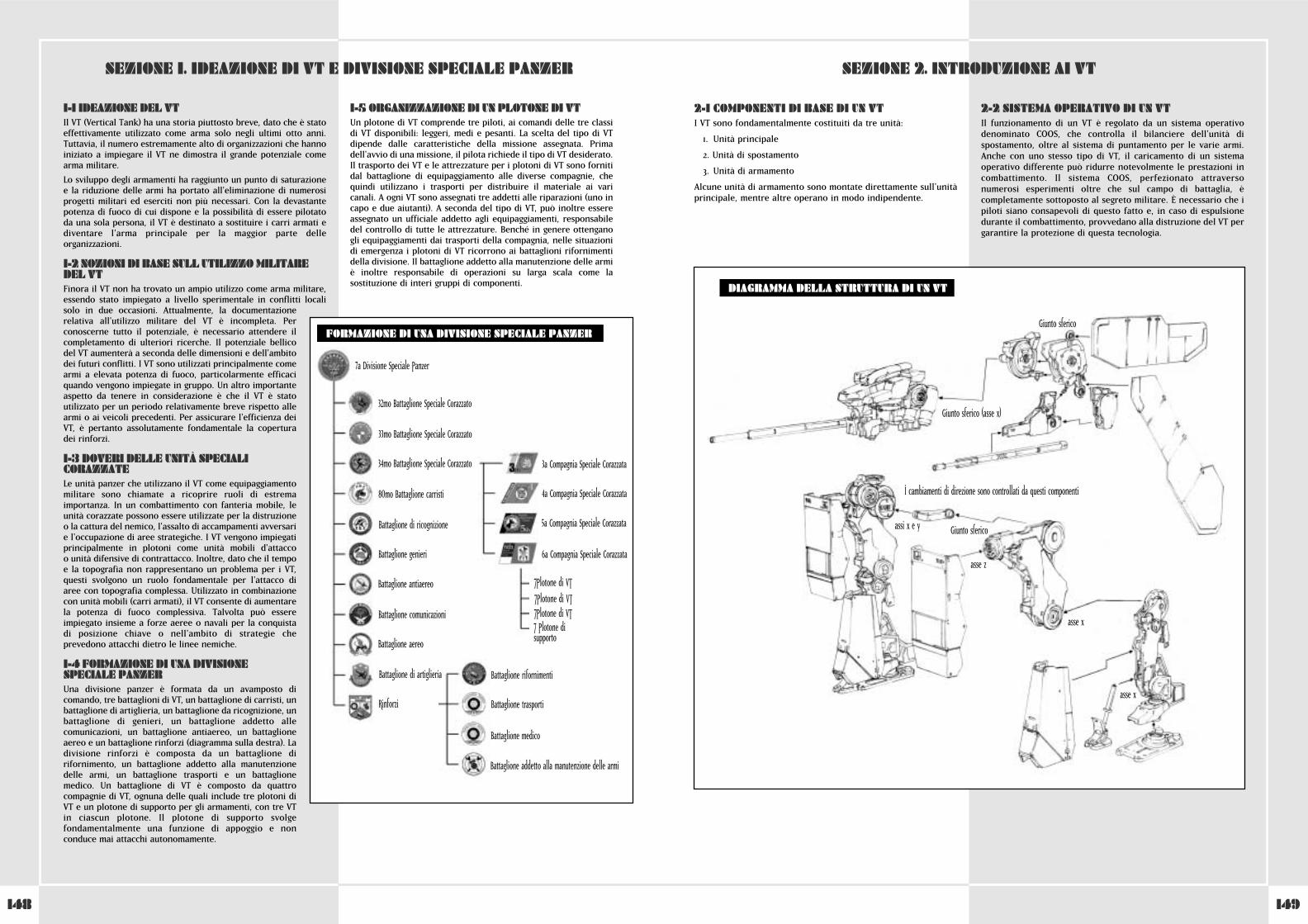
149148
2-1 COMPONENTI DI BASE DI UN VTI VT sono fondamentalmente costituiti da tre unità:
1. Unità principale
2. Unità di spostamento
3. Unità di armamento
Alcune unità di armamento sono montate direttamente sull'unitàprincipale, mentre altre operano in modo indipendente.
2-2 SISTEMA OPERATIVO DI UN VTIl funzionamento di un VT è regolato da un sistema operativodenominato COOS, che controlla il bilanciere dell'unità dispostamento, oltre al sistema di puntamento per le varie armi.Anche con uno stesso tipo di VT, il caricamento di un sistemaoperativo differente può ridurre notevolmente le prestazioni incombattimento. Il sistema COOS, perfezionato attraversonumerosi esperimenti oltre che sul campo di battaglia, ècompletamente sottoposto al segreto militare. È necessario che ipiloti siano consapevoli di questo fatto e, in caso di espulsionedurante il combattimento, provvedano alla distruzione del VT pergarantire la protezione di questa tecnologia.
1-1 IDEAZIONE DEL VTIl VT (Vertical Tank) ha una storia piuttosto breve, dato che è statoeffettivamente utilizzato come arma solo negli ultimi otto anni.Tuttavia, il numero estremamente alto di organizzazioni che hannoiniziato a impiegare il VT ne dimostra il grande potenziale comearma militare.
Lo sviluppo degli armamenti ha raggiunto un punto di saturazione e la riduzione delle armi ha portato all'eliminazione di numerosiprogetti militari ed eserciti non più necessari. Con la devastantepotenza di fuoco di cui dispone e la possibilità di essere pilotatoda una sola persona, il VT è destinato a sostituire i carri armati ediventare l'arma principale per la maggior parte delleorganizzazioni.
1-2 NOZIONI DI BASE SULL UTILIZZO MILITAREDEL VTFinora il VT non ha trovato un ampio utilizzo come arma militare,essendo stato impiegato a livello sperimentale in conflitti localisolo in due occasioni. Attualmente, la documentazionerelativa all'utilizzo militare del VT è incompleta. Perconoscerne tutto il potenziale, è necessario attendere ilcompletamento di ulteriori ricerche. Il potenziale bellicodel VT aumenterà a seconda delle dimensioni e dell'ambitodei futuri conflitti. I VT sono utilizzati principalmente comearmi a elevata potenza di fuoco, particolarmente efficaciquando vengono impiegate in gruppo. Un altro importanteaspetto da tenere in considerazione è che il VT è statoutilizzato per un periodo relativamente breve rispetto allearmi o ai veicoli precedenti. Per assicurare l'efficienza deiVT, è pertanto assolutamente fondamentale la coperturadei rinforzi.
1-3 DOVERI DELLE UNITÀ SPECIALICORAZZATE Le unità panzer che utilizzano il VT come equipaggiamentomilitare sono chiamate a ricoprire ruoli di estremaimportanza. In un combattimento con fanteria mobile, leunità corazzate possono essere utilizzate per la distruzioneo la cattura del nemico, l'assalto di accampamenti avversarie l'occupazione di aree strategiche. I VT vengono impiegatiprincipalmente in plotoni come unità mobili d'attacco o unità difensive di contrattacco. Inoltre, dato che il tempoe la topografia non rappresentano un problema per i VT,questi svolgono un ruolo fondamentale per l'attacco diaree con topografia complessa. Utilizzato in combinazionecon unità mobili (carri armati), il VT consente di aumentarela potenza di fuoco complessiva. Talvolta può essereimpiegato insieme a forze aeree o navali per la conquistadi posizione chiave o nell'ambito di strategie cheprevedono attacchi dietro le linee nemiche.
1-4 FORMAZIONE DI UNA DIVISIONESPECIALE PANZERUna divisione panzer è formata da un avamposto dicomando, tre battaglioni di VT, un battaglione di carristi, unbattaglione di artiglieria, un battaglione da ricognizione, unbattaglione di genieri, un battaglione addetto allecomunicazioni, un battaglione antiaereo, un battaglioneaereo e un battaglione rinforzi (diagramma sulla destra). Ladivisione rinforzi è composta da un battaglione dirifornimento, un battaglione addetto alla manutenzionedelle armi, un battaglione trasporti e un battaglionemedico. Un battaglione di VT è composto da quattrocompagnie di VT, ognuna delle quali include tre plotoni diVT e un plotone di supporto per gli armamenti, con tre VTin ciascun plotone. Il plotone di supporto svolgefondamentalmente una funzione di appoggio e nonconduce mai attacchi autonomamente.
1-5 ORGANIZZAZIONE DI UN PLOTONE DI VTUn plotone di VT comprende tre piloti, ai comandi delle tre classidi VT disponibili: leggeri, medi e pesanti. La scelta del tipo di VTdipende dalle caratteristiche della missione assegnata. Primadell'avvio di una missione, il pilota richiede il tipo di VT desiderato.Il trasporto dei VT e le attrezzature per i plotoni di VT sono fornitidal battaglione di equipaggiamento alle diverse compagnie, chequindi utilizzano i trasporti per distribuire il materiale ai varicanali. A ogni VT sono assegnati tre addetti alle riparazioni (uno incapo e due aiutanti). A seconda del tipo di VT, può inoltre essereassegnato un ufficiale addetto agli equipaggiamenti, responsabiledel controllo di tutte le attrezzature. Benché in genere ottenganogli equipaggiamenti dai trasporti della compagnia, nelle situazionidi emergenza i plotoni di VT ricorrono ai battaglioni rifornimentidella divisione. Il battaglione addetto alla manutenzione delle armiè inoltre responsabile di operazioni su larga scala come lasostituzione di interi gruppi di componenti.
SEZIONE 1. IDEAZIONE DI VT E DIVISIONE SPECIALE PANZER SEZIONE 2. INTRODUZIONE AI VT
7a Divisione Speciale Panzer
32mo Battaglione Speciale Corazzato
33mo Battaglione Speciale Corazzato
34mo Battaglione Speciale Corazzato 3a Compagnia Speciale Corazzata
4a Compagnia Speciale Corazzata
5a Compagnia Speciale Corazzata
6a Compagnia Speciale Corazzata
‡Plotone di VT‡Plotone di VT‡Plotone di VT‡ Plotone disupporto
Battaglione rifornimenti
Battaglione trasporti
Battaglione medico
Battaglione addetto alla manutenzione delle armi
80mo Battaglione carristi
Battaglione di ricognizione
Battaglione genieri
Battaglione antiaereo
Battaglione comunicazioni
Battaglione aereo
Battaglione di artiglieria
Rinforzi
FORMAZIONE DI UNA DIVISIONE SPECIALE PANZER
DIAGRAMMA DELLA STRUTTURA DI UN VT
Giunto sferico (asse x)
assi x e y
asse z
asse x
asse x
I cambiamenti di direzione sono controllati da questi componenti
Giunto sferico
Giunto sferico
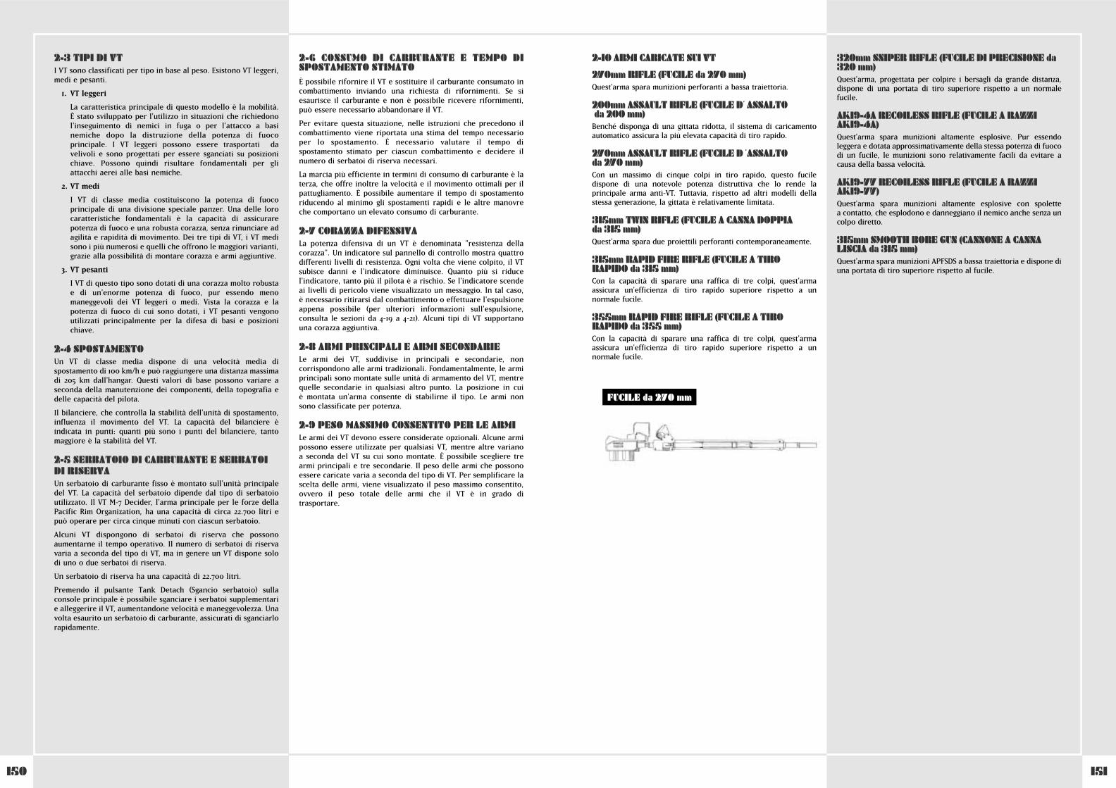
151150
2-10 ARMI CARICATE SUI VT
270mm RIFLE (FUCILE da 270 mm)Quest'arma spara munizioni perforanti a bassa traiettoria.
200mm ASSAULT RIFLE (FUCILE D´ ASSALTOda 200 mm)Benché disponga di una gittata ridotta, il sistema di caricamentoautomatico assicura la più elevata capacità di tiro rapido.
270mm ASSAULT RIFLE (FUCILE D ´ASSALTO da 270 mm)Con un massimo di cinque colpi in tiro rapido, questo fuciledispone di una notevole potenza distruttiva che lo rende laprincipale arma anti-VT. Tuttavia, rispetto ad altri modelli dellastessa generazione, la gittata è relativamente limitata.
315mm TWIN RIFLE (FUCILE A CANNA DOPPIA da 315 mm)Quest'arma spara due proiettili perforanti contemporaneamente.
315mm RAPID FIRE RIFLE (FUCILE A TIRORAPIDO da 315 mm)Con la capacità di sparare una raffica di tre colpi, quest'armaassicura un'efficienza di tiro rapido superiore rispetto a unnormale fucile.
355mm RAPID FIRE RIFLE (FUCILE A TIRORAPIDO da 355 mm)Con la capacità di sparare una raffica di tre colpi, quest'armaassicura un'efficienza di tiro rapido superiore rispetto a unnormale fucile.
320mm SNIPER RIFLE (FUCILE DI PRECISIONE da320 mm)Quest'arma, progettata per colpire i bersagli da grande distanza,dispone di una portata di tiro superiore rispetto a un normalefucile.
AK19-4A RECOILESS RIFLE (FUCILE A RAZZIAK19-4A)Quest'arma spara munizioni altamente esplosive. Pur essendoleggera e dotata approssimativamente della stessa potenza di fuocodi un fucile, le munizioni sono relativamente facili da evitare acausa della bassa velocità.
AK19-77 RECOILESS RIFLE (FUCILE A RAZZIAK19-77)Quest'arma spara munizioni altamente esplosive con spolette a contatto, che esplodono e danneggiano il nemico anche senza uncolpo diretto.
315mm SMOOTH BORE GUN (CANNONE A CANNALISCIA da 315 mm)Quest'arma spara munizioni APFSDS a bassa traiettoria e dispone diuna portata di tiro superiore rispetto al fucile.
2-3 TIPI DI VTI VT sono classificati per tipo in base al peso. Esistono VT leggeri,medi e pesanti.
1. VT leggeri
La caratteristica principale di questo modello è la mobilità. È stato sviluppato per l'utilizzo in situazioni che richiedonol'inseguimento di nemici in fuga o per l'attacco a basinemiche dopo la distruzione della potenza di fuocoprincipale. I VT leggeri possono essere trasportati davelivoli e sono progettati per essere sganciati su posizionichiave. Possono quindi risultare fondamentali per gliattacchi aerei alle basi nemiche.
2. VT medi
I VT di classe media costituiscono la potenza di fuocoprincipale di una divisione speciale panzer. Una delle lorocaratteristiche fondamentali è la capacità di assicurarepotenza di fuoco e una robusta corazza, senza rinunciare adagilità e rapidità di movimento. Dei tre tipi di VT, i VT medisono i più numerosi e quelli che offrono le maggiori varianti,grazie alla possibilità di montare corazza e armi aggiuntive.
3. VT pesanti
I VT di questo tipo sono dotati di una corazza molto robusta e di un'enorme potenza di fuoco, pur essendo menomaneggevoli dei VT leggeri o medi. Vista la corazza e lapotenza di fuoco di cui sono dotati, i VT pesanti vengonoutilizzati principalmente per la difesa di basi e posizionichiave.
2-4 SPOSTAMENTOUn VT di classe media dispone di una velocità media dispostamento di 100 km/h e può raggiungere una distanza massimadi 205 km dall'hangar. Questi valori di base possono variare aseconda della manutenzione dei componenti, della topografia edelle capacità del pilota.
Il bilanciere, che controlla la stabilità dell'unità di spostamento,influenza il movimento del VT. La capacità del bilanciere èindicata in punti: quanti più sono i punti del bilanciere, tantomaggiore è la stabilità del VT.
2-5 SERBATOIO DI CARBURANTE E SERBATOIDI RISERVAUn serbatoio di carburante fisso è montato sull'unità principaledel VT. La capacità del serbatoio dipende dal tipo di serbatoioutilizzato. Il VT M-7 Decider, l'arma principale per le forze dellaPacific Rim Organization, ha una capacità di circa 22.700 litri epuò operare per circa cinque minuti con ciascun serbatoio.
Alcuni VT dispongono di serbatoi di riserva che possonoaumentarne il tempo operativo. Il numero di serbatoi di riservavaria a seconda del tipo di VT, ma in genere un VT dispone solodi uno o due serbatoi di riserva.
Un serbatoio di riserva ha una capacità di 22.700 litri.
Premendo il pulsante Tank Detach (Sgancio serbatoio) sullaconsole principale è possibile sganciare i serbatoi supplementari e alleggerire il VT, aumentandone velocità e maneggevolezza. Unavolta esaurito un serbatoio di carburante, assicurati di sganciarlorapidamente.
2-6 CONSUMO DI CARBURANTE E TEMPO DISPOSTAMENTO STIMATOÈ possibile rifornire il VT e sostituire il carburante consumato incombattimento inviando una richiesta di rifornimenti. Se siesaurisce il carburante e non è possibile ricevere rifornimenti,può essere necessario abbandonare il VT.
Per evitare questa situazione, nelle istruzioni che precedono ilcombattimento viene riportata una stima del tempo necessarioper lo spostamento. È necessario valutare il tempo dispostamento stimato per ciascun combattimento e decidere ilnumero di serbatoi di riserva necessari.
La marcia più efficiente in termini di consumo di carburante è laterza, che offre inoltre la velocità e il movimento ottimali per ilpattugliamento. È possibile aumentare il tempo di spostamentoriducendo al minimo gli spostamenti rapidi e le altre manovreche comportano un elevato consumo di carburante.
2-7 CORAZZA DIFENSIVALa potenza difensiva di un VT è denominata "resistenza dellacorazza". Un indicatore sul pannello di controllo mostra quattrodifferenti livelli di resistenza. Ogni volta che viene colpito, il VTsubisce danni e l'indicatore diminuisce. Quanto più si riducel'indicatore, tanto più il pilota è a rischio. Se l'indicatore scendeai livelli di pericolo viene visualizzato un messaggio. In tal caso, è necessario ritirarsi dal combattimento o effettuare l'espulsioneappena possibile (per ulteriori informazioni sull'espulsione,consulta le sezioni da 4-19 a 4-21). Alcuni tipi di VT supportanouna corazza aggiuntiva.
2-8 ARMI PRINCIPALI E ARMI SECONDARIELe armi dei VT, suddivise in principali e secondarie, noncorrispondono alle armi tradizionali. Fondamentalmente, le armiprincipali sono montate sulle unità di armamento del VT, mentrequelle secondarie in qualsiasi altro punto. La posizione in cui è montata un'arma consente di stabilirne il tipo. Le armi nonsono classificate per potenza.
2-9 PESO MASSIMO CONSENTITO PER LE ARMILe armi dei VT devono essere considerate opzionali. Alcune armipossono essere utilizzate per qualsiasi VT, mentre altre variano a seconda del VT su cui sono montate. È possibile scegliere trearmi principali e tre secondarie. Il peso delle armi che possonoessere caricate varia a seconda del tipo di VT. Per semplificare lascelta delle armi, viene visualizzato il peso massimo consentito,ovvero il peso totale delle armi che il VT è in grado ditrasportare.
FUCILE da 270 mm
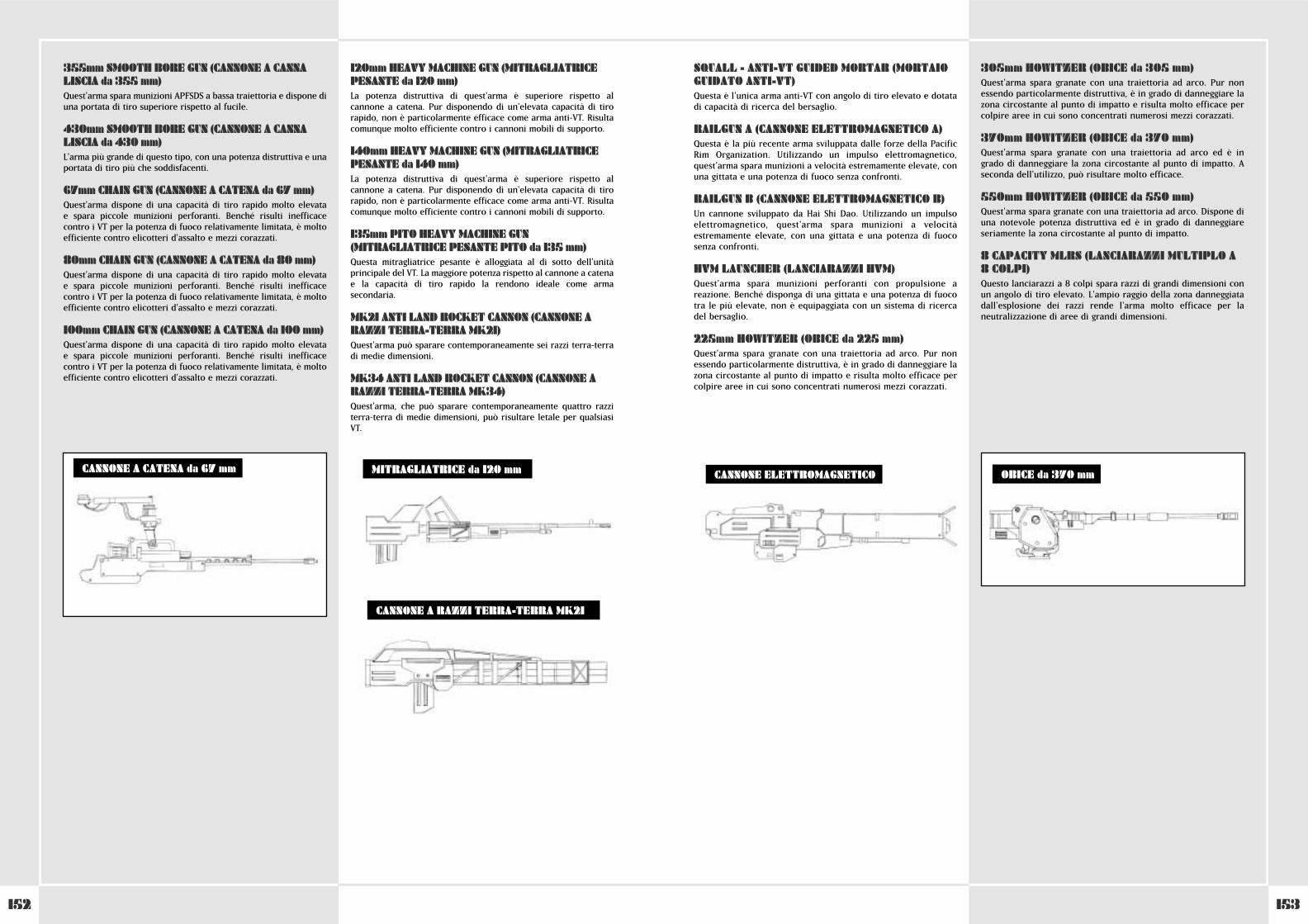
153152
SQUALL - ANTI-VT GUIDED MORTAR (MORTAIOGUIDATO ANTI-VT)Questa è l'unica arma anti-VT con angolo di tiro elevato e dotatadi capacità di ricerca del bersaglio.
RAILGUN A (CANNONE ELETTROMAGNETICO A)Questa è la più recente arma sviluppata dalle forze della PacificRim Organization. Utilizzando un impulso elettromagnetico,quest'arma spara munizioni a velocità estremamente elevate, conuna gittata e una potenza di fuoco senza confronti.
RAILGUN B (CANNONE ELETTROMAGNETICO B)Un cannone sviluppato da Hai Shi Dao. Utilizzando un impulsoelettromagnetico, quest'arma spara munizioni a velocitàestremamente elevate, con una gittata e una potenza di fuocosenza confronti.
HVM LAUNCHER (LANCIARAZZI HVM)Quest'arma spara munizioni perforanti con propulsione areazione. Benché disponga di una gittata e una potenza di fuocotra le più elevate, non è equipaggiata con un sistema di ricercadel bersaglio.
225mm HOWITZER (OBICE da 225 mm)Quest'arma spara granate con una traiettoria ad arco. Pur nonessendo particolarmente distruttiva, è in grado di danneggiare lazona circostante al punto di impatto e risulta molto efficace percolpire aree in cui sono concentrati numerosi mezzi corazzati.
305mm HOWITZER (OBICE da 305 mm)Quest'arma spara granate con una traiettoria ad arco. Pur nonessendo particolarmente distruttiva, è in grado di danneggiare lazona circostante al punto di impatto e risulta molto efficace percolpire aree in cui sono concentrati numerosi mezzi corazzati.
370mm HOWITZER (OBICE da 370 mm)Quest'arma spara granate con una traiettoria ad arco ed è ingrado di danneggiare la zona circostante al punto di impatto. Aseconda dell'utilizzo, può risultare molto efficace.
550mm HOWITZER (OBICE da 550 mm)Quest'arma spara granate con una traiettoria ad arco. Dispone diuna notevole potenza distruttiva ed è in grado di danneggiareseriamente la zona circostante al punto di impatto.
8 CAPACITY MLRS (LANCIARAZZI MULTIPLO A8 COLPI)Questo lanciarazzi a 8 colpi spara razzi di grandi dimensioni conun angolo di tiro elevato. L'ampio raggio della zona danneggiatadall'esplosione dei razzi rende l'arma molto efficace per laneutralizzazione di aree di grandi dimensioni.
355mm SMOOTH BORE GUN (CANNONE A CANNALISCIA da 355 mm)Quest'arma spara munizioni APFSDS a bassa traiettoria e dispone diuna portata di tiro superiore rispetto al fucile.
430mm SMOOTH BORE GUN (CANNONE A CANNALISCIA da 430 mm)L'arma più grande di questo tipo, con una potenza distruttiva e unaportata di tiro più che soddisfacenti.
67mm CHAIN GUN (CANNONE A CATENA da 67 mm)Quest'arma dispone di una capacità di tiro rapido molto elevata e spara piccole munizioni perforanti. Benché risulti inefficacecontro i VT per la potenza di fuoco relativamente limitata, è moltoefficiente contro elicotteri d'assalto e mezzi corazzati.
80mm CHAIN GUN (CANNONE A CATENA da 80 mm)Quest'arma dispone di una capacità di tiro rapido molto elevata e spara piccole munizioni perforanti. Benché risulti inefficacecontro i VT per la potenza di fuoco relativamente limitata, è moltoefficiente contro elicotteri d'assalto e mezzi corazzati.
100mm CHAIN GUN (CANNONE A CATENA da 100 mm)Quest'arma dispone di una capacità di tiro rapido molto elevata e spara piccole munizioni perforanti. Benché risulti inefficacecontro i VT per la potenza di fuoco relativamente limitata, è moltoefficiente contro elicotteri d'assalto e mezzi corazzati.
120mm HEAVY MACHINE GUN (MITRAGLIATRICEPESANTE da 120 mm)La potenza distruttiva di quest'arma è superiore rispetto alcannone a catena. Pur disponendo di un'elevata capacità di tirorapido, non è particolarmente efficace come arma anti-VT. Risultacomunque molto efficiente contro i cannoni mobili di supporto.
140mm HEAVY MACHINE GUN (MITRAGLIATRICEPESANTE da 140 mm)La potenza distruttiva di quest'arma è superiore rispetto alcannone a catena. Pur disponendo di un'elevata capacità di tirorapido, non è particolarmente efficace come arma anti-VT. Risultacomunque molto efficiente contro i cannoni mobili di supporto.
135mm PITO HEAVY MACHINE GUN(MITRAGLIATRICE PESANTE PITO da 135 mm)Questa mitragliatrice pesante è alloggiata al di sotto dell'unitàprincipale del VT. La maggiore potenza rispetto al cannone a catena e la capacità di tiro rapido la rendono ideale come armasecondaria.
MK21 ANTI LAND ROCKET CANNON (CANNONE ARAZZI TERRA-TERRA MK21)Quest'arma può sparare contemporaneamente sei razzi terra-terradi medie dimensioni.
MK34 ANTI LAND ROCKET CANNON (CANNONE ARAZZI TERRA-TERRA MK34)Quest'arma, che può sparare contemporaneamente quattro razziterra-terra di medie dimensioni, può risultare letale per qualsiasiVT.
CANNONE A CATENA da 67 mm MITRAGLIATRICE da 120 mm CANNONE ELETTROMAGNETICO OBICE da 370 mm
CANNONE A RAZZI TERRA-TERRA MK21
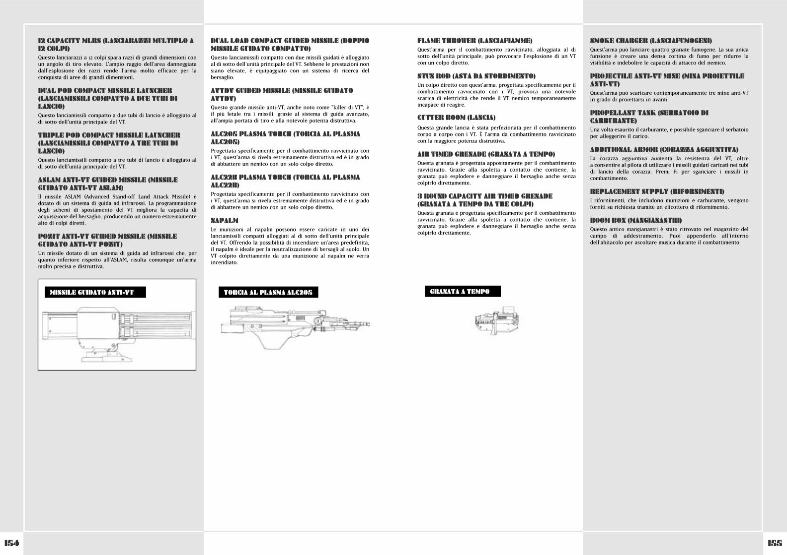
155154
FLAME THROWER (LANCIAFIAMME)Quest'arma per il combattimento ravvicinato, alloggiata al disotto dell'unità principale, può provocare l'esplosione di un VTcon un colpo diretto.
STUN ROD (ASTA DA STORDIMENTO)Un colpo diretto con quest'arma, progettata specificamente per ilcombattimento ravvicinato con i VT, provoca una notevolescarica di elettricità che rende il VT nemico temporaneamenteincapace di reagire.
CUTTER BOOM (LANCIA)Questa grande lancia è stata perfezionata per il combattimentocorpo a corpo con i VT. È l'arma da combattimento ravvicinatocon la maggiore potenza distruttiva.
AIR TIMED GRENADE (GRANATA A TEMPO)Questa granata è progettata appositamente per il combattimentoravvicinato. Grazie alla spoletta a contatto che contiene, lagranata può esplodere e danneggiare il bersaglio anche senzacolpirlo direttamente.
3 ROUND CAPACITY AIR TIMED GRENADE(GRANATA A TEMPO DA TRE COLPI)Questa granata è progettata specificamente per il combattimentoravvicinato. Grazie alla spoletta a contatto che contiene, lagranata può esplodere e danneggiare il bersaglio anche senzacolpirlo direttamente.
SMOKE CHARGER (LANCIAFUMOGENI)Quest'arma può lanciare quattro granate fumogene. La sua unicafunzione è creare una densa cortina di fumo per ridurre lavisibilità e indebolire le capacità di attacco del nemico.
PROJECTILE ANTI-VT MINE (MINA PROIETTILEANTI-VT)Quest'arma può scaricare contemporaneamente tre mine anti-VTin grado di proiettarsi in avanti.
PROPELLANT TANK (SERBATOIO DICARBURANTE)Una volta esaurito il carburante, è possibile sganciare il serbatoioper alleggerire il carico.
ADDITIONAL ARMOR (CORAZZA AGGIUNTIVA)La corazza aggiuntiva aumenta la resistenza del VT, oltre a consentire al pilota di utilizzare i missili guidati caricati nei tubidi lancio della corazza. Premi F1 per sganciare i missili incombattimento.
REPLACEMENT SUPPLY (RIFORNIMENTI)I rifornimenti, che includono munizioni e carburante, vengonoforniti su richiesta tramite un elicottero di rifornimento.
BOOM BOX (MANGIANASTRI)Questo antico mangianastri è stato ritrovato nel magazzino delcampo di addestramento. Puoi appenderlo all'internodell'abitacolo per ascoltare musica durante il combattimento.
12 CAPACITY MLRS (LANCIARAZZI MULTIPLO A12 COLPI)Questo lanciarazzi a 12 colpi spara razzi di grandi dimensioni conun angolo di tiro elevato. L'ampio raggio dell'area danneggiatadall'esplosione dei razzi rende l'arma molto efficace per laconquista di aree di grandi dimensioni.
DUAL POD COMPACT MISSILE LAUNCHER(LANCIAMISSILI COMPATTO A DUE TUBI DILANCIO) Questo lanciamissili compatto a due tubi di lancio è alloggiato aldi sotto dell'unità principale del VT.
TRIPLE POD COMPACT MISSILE LAUNCHER(LANCIAMISSILI COMPATTO A TRE TUBI DILANCIO) Questo lanciamissili compatto a tre tubi di lancio è alloggiato aldi sotto dell'unità principale del VT.
ASLAM ANTI-VT GUIDED MISSILE (MISSILEGUIDATO ANTI-VT ASLAM)Il missile ASLAM (Advanced Stand-0ff Land Attack Missile) èdotato di un sistema di guida ad infrarossi. La programmazionedegli schemi di spostamento del VT migliora la capacità diacquisizione del bersaglio, producendo un numero estremamentealto di colpi diretti.
POZIT ANTI-VT GUIDED MISSILE (MISSILEGUIDATO ANTI-VT POZIT)Un missile dotato di un sistema di guida ad infrarossi che, perquanto inferiore rispetto all'ASLAM, risulta comunque un'armamolto precisa e distruttiva.
DUAL LOAD COMPACT GUIDED MISSILE (DOPPIOMISSILE GUIDATO COMPATTO)Questo lanciamissili compatto con due missili guidati è alloggiatoal di sotto dell'unità principale del VT. Sebbene le prestazioni nonsiano elevate, è equipaggiato con un sistema di ricerca delbersaglio.
AVTDV GUIDED MISSILE (MISSILE GUIDATOAVTDV)Questo grande missile anti-VT, anche noto come "killer di VT", èil più letale tra i missili, grazie al sistema di guida avanzato,all'ampia portata di tiro e alla notevole potenza distruttiva.
ALC205 PLASMA TORCH (TORCIA AL PLASMAALC205)Progettata specificamente per il combattimento ravvicinato con i VT, quest'arma si rivela estremamente distruttiva ed è in gradodi abbattere un nemico con un solo colpo diretto.
ALC22B PLASMA TORCH (TORCIA AL PLASMAALC22B)Progettata specificamente per il combattimento ravvicinato con i VT, quest'arma si rivela estremamente distruttiva ed è in gradodi abbattere un nemico con un solo colpo diretto.
NAPALMLe munizioni al napalm possono essere caricate in uno deilanciamissili compatti alloggiati al di sotto dell'unità principaledel VT. Offrendo la possibilità di incendiare un'area predefinita,il napalm è ideale per la neutralizzazione di bersagli al suolo. UnVT colpito direttamente da una munizione al napalm ne verràincendiato.
TORCIA AL PLASMA ALC205MISSILE GUIDATO ANTI-VT GRANATA A TEMPO
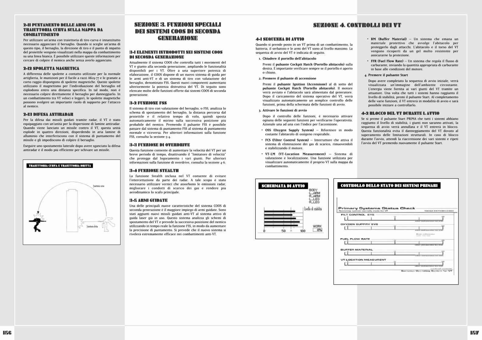
157156
2-11 PUNTAMENTO DELLE ARMI CONTRAIETTORIA CURVA SULLA MAPPA DACOMBATTIMENTOPer utilizzare un'arma con traiettoria di tiro curva è innanzituttonecessario agganciare il bersaglio. Quando si sceglie un'arma diquesto tipo, il bersaglio, la direzione di tiro e il punto di impattodel proiettile vengono visualizzati nella mappa da combattimentosu una linea bianca. È possibile utilizzare queste informazioni percercare di colpire il nemico anche senza averlo agganciato.
2-12 SPOLETTA MAGNETICAA differenza delle spolette a contatto utilizzate per la normaleartiglieria, le munizioni per il fucile a razzi AK19-77 e le granate acorto raggio dispongono di spolette magnetiche. Queste spoletteutilizzano il magnetismo per l'individuazione del bersaglio edesplodono entro una distanza specifica. In tal modo, non ènecessario colpire direttamente il bersaglio per danneggiarlo. Inun combattimento tra VT veloci e leggeri, le spolette magnetichepossono svolgere un importante ruolo di supporto per l'attaccoal nemico.
2-13 DIFESA ANTIRADARPer la difesa dai missili guidati tramite radar, il VT è statoequipaggiato con un'unità per la dispersione di lamine antiradar.Quando viene lanciato un missile contro il VT, questa unitàesplode in quattro direzioni, disperdendo in aria lamine dialluminio che interferiscono con il sistema di puntamento delmissile e gli impediscono di colpire il bersaglio.
Eseguire uno spostamento laterale dopo avere sganciato la difesaantiradar è il modo più efficiente per schivare un missile.
Traiettoria curva
Traiettoria dritta
TRAIETTORIA CURVA E TRAIETTORIA DRITTA
3-1 ELEMENTI INTRODOTTI NEI SISTEMI COOSDI SECONDA GENERAZIONEAttualmente il sistema COOS che controlla tutti i movimenti delVT è giunto alla seconda generazione, ampliando le funzionalitàdisponibili per i VT. Oltre a una superiore potenza dielaborazione, il COOS dispone di un nuovo sistema di guida perle armi anti-VT e di un sistema di tiro con valutazione delbersaglio, denominato FSS. Questi nuovi componenti aumentanoulteriormente la potenza distruttiva del VT. Di seguito sonoelencate molte delle funzioni offerte dai sistemi COOS di secondagenerazione.
3-2 FUNZIONE FSSIl sistema di tiro con valutazione del bersaglio, o FSS, analizza loschema di spostamento del bersaglio, la distanza percorsa dalproiettile e il relativo tempo di volo, quindi spostaautomaticamente il mirino sulla successiva posizione piùprobabile del nemico. Premendo il pulsante FSS è possibilepassare dal sistema di puntamento FSS al sistema di puntamentonormale e viceversa. Per ulteriori informazioni sulla funzioneFSS, consulta la sezione 5-4.
3-3 FUNZIONE DI OVERDRIVEQuesta funzione consente di aumentare la velocità del VT per unbreve periodo di tempo, disattivando il "limitatore di velocità"che protegge dal logoramento i vari giunti. Per ulterioriinformazioni sulla funzione di overdrive, consulta la sezione 4-6.
3-4 FUNZIONE STEALTHLa funzione Stealth inclusa nel VT consente di evitarel'intercettazione da parte dei radar. A tale scopo è statonecessario utilizzare vernici che assorbono le emissioni radar,migliorare i condotti di scarico dei gas e rendere piùaerodinamico lo scafo principale.
3-5 ARMI GUIDATEUna delle principali nuove caratteristiche del sistema COOS diseconda generazione è il maggiore impiego di armi guidate. Sonostati aggiunti nuovi missili guidati anti-VT al sistema attivo diguida laser già in uso. Questo sistema analizza gli schemi dispostamento del VT e prevede la successiva posizione del nemicoutilizzando in tempo reale la funzione FSS, in modo da aumentarela precisione di puntamento. Si prevede che il nuovo sistema sirivelerà estremamente efficace nei combattimenti anti-VT.
SEZIONE 3. FUNZIONI SPECIALIDEI SISTEMI COOS DI SECONDA
GENERAZIONE 4-1 SEQUENZA DI AVVIOQuando si prende posto in un VT prima di un combattimento, labatteria, il serbatoio e le armi del VT sono al livello massimo. Lasequenza di avvio del VT è indicata di seguito.
1. Chiudere il portello dell'abitacolo
Premi il pulsante Cockpit Hatch (Portello abitacolo) sulladestra. È importante verificare sempre se il portello è aperto o chiuso.
2. Premere il pulsante di accensione
Premi il pulsante Ignition (Accensione) al di sotto delpulsante Cockpit Hatch (Portello abitacolo). Il motoreverrà avviato e l'abitacolo sarà alimentato dal generatore.Dopo il caricamento del sistema operativo del VT, verràvisualizzato automaticamente un semplice controllo dellefunzioni, prima della schermata delle funzioni di avvio.
3. Attivare le funzioni di avvio
Dopo il controllo delle funzioni, è necessario attivareognuna delle seguenti funzioni per verificarne l'operatività.Azionale una ad una con l'indice per l'accensione.
• OSS (Oxygen Supply System) – Rifornisce in modocostante l'abitacolo di ossigeno respirabile.
• FCS (Filter Control System) – Interruttore che attiva ilsistema di eliminazione dei gas di scarico, rimuovendoli e stabilizzando il motore.
• VT-LM (VT-Location Measurement) – Sistema divalutazione e localizzazione. Una funzione utilizzata pervisualizzare automaticamente il proprio VT sulla mappa dacombattimento.
• BM (Buffer Material) – Un sistema che emana unmateriale protettivo che avvolge l'abitacolo perproteggerlo dagli attacchi. L'abitacolo e il torso del VTvengono ricoperti da un gel molto resistente perassicurarne la protezione.
• FFR (Fuel Flow Rate) – Un sistema che regola il flusso dicarburante, inviando la quantità appropriata di carburantein base alle condizioni del motore.
4. Premere il pulsante Start
Dopo avere completato la sequenza di avvio iniziale, verràvisualizzata un'immagine dell'ambiente circostante.L'energia viene fornita ai vari giunti del VT tramite unattuatore. Una volta che tutti i sistemi hanno raggiunto illivello di stabilità, premi il pulsante Start. Al completamentodelle varie funzioni, il VT entrerà in modalità di avvio e saràpossibile iniziare a controllarlo.
4-2 BLOCCO DEL VT DURANTE L AVVIOSe si preme il pulsante Start PRIMA che tutti i sistemi abbianoraggiunto il livello di stabilità, i giunti non saranno attivati, lasequenza di avvio verrà annullata e il VT entrerà in blocco.Questa funzionalità evita il danneggiamento del VT dovuto alsuperamento delle limitazioni strutturali. In caso di bloccodurante l'avvio, attendi la riaccensione dei vari sistemi e ripetil'avvio del VT premendo nuovamente il pulsante Start.
SEZIONE 4. CONTROLLI DEI VT
Livello di stabilità
CONTROLLO DELLO STATO DEI SISTEMI PRIMARISCHERMATA DI AVVIO
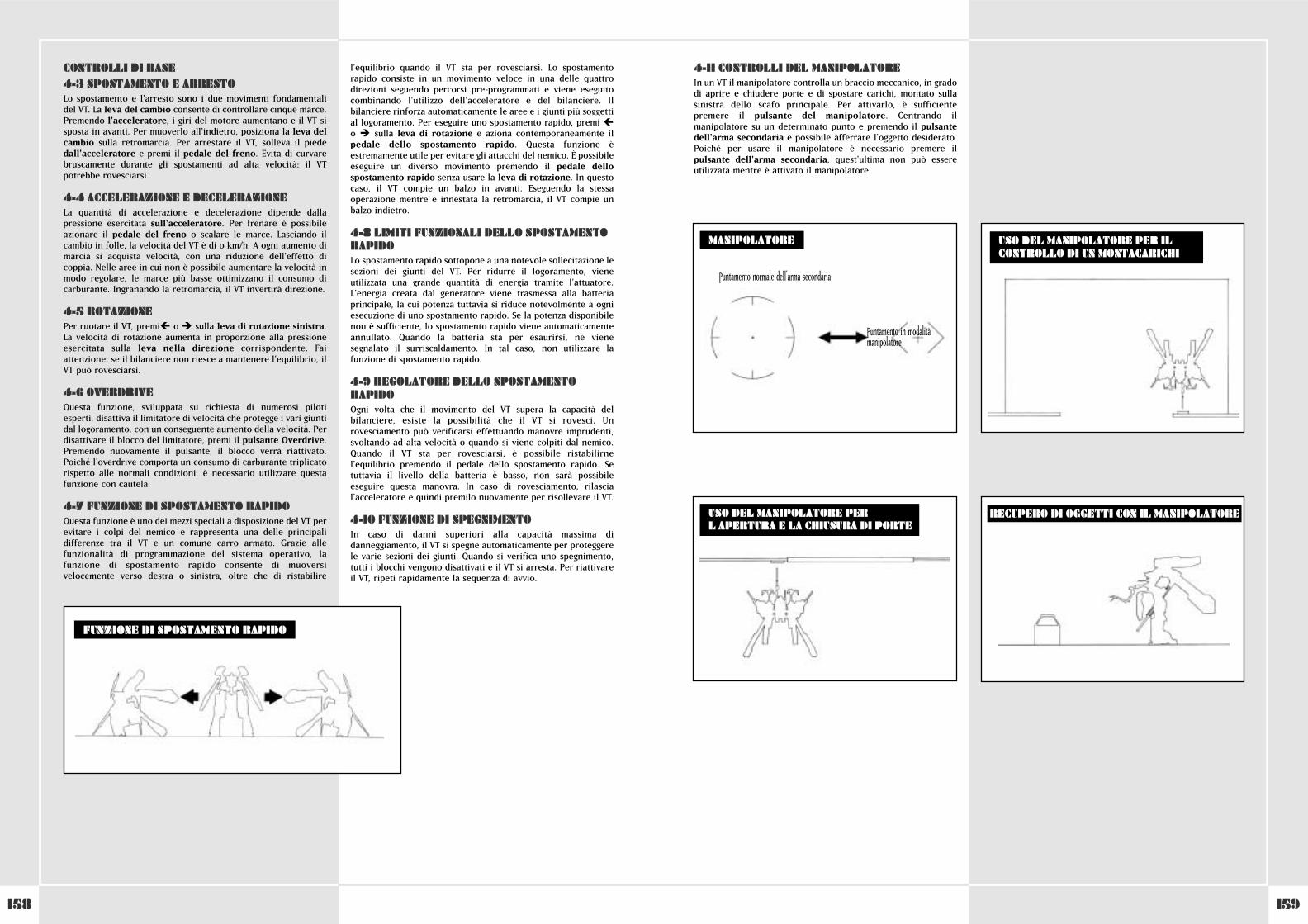
159158
CONTROLLI DI BASE4-3 SPOSTAMENTO E ARRESTOLo spostamento e l'arresto sono i due movimenti fondamentalidel VT. La leva del cambio consente di controllare cinque marce.Premendo l'acceleratore, i giri del motore aumentano e il VT sisposta in avanti. Per muoverlo all'indietro, posiziona la leva delcambio sulla retromarcia. Per arrestare il VT, solleva il piededall'acceleratore e premi il pedale del freno. Evita di curvarebruscamente durante gli spostamenti ad alta velocità: il VTpotrebbe rovesciarsi.
4-4 ACCELERAZIONE E DECELERAZIONELa quantità di accelerazione e decelerazione dipende dallapressione esercitata sull'acceleratore. Per frenare è possibileazionare il pedale del freno o scalare le marce. Lasciando ilcambio in folle, la velocità del VT è di 0 km/h. A ogni aumento dimarcia si acquista velocità, con una riduzione dell'effetto dicoppia. Nelle aree in cui non è possibile aumentare la velocità inmodo regolare, le marce più basse ottimizzano il consumo dicarburante. Ingranando la retromarcia, il VT invertirà direzione.
4-5 ROTAZIONEPer ruotare il VT, premi� o � sulla leva di rotazione sinistra.La velocità di rotazione aumenta in proporzione alla pressioneesercitata sulla leva nella direzione corrispondente. Faiattenzione: se il bilanciere non riesce a mantenere l'equilibrio, ilVT può rovesciarsi.
4-6 OVERDRIVEQuesta funzione, sviluppata su richiesta di numerosi pilotiesperti, disattiva il limitatore di velocità che protegge i vari giuntidal logoramento, con un conseguente aumento della velocità. Perdisattivare il blocco del limitatore, premi il pulsante Overdrive.Premendo nuovamente il pulsante, il blocco verrà riattivato.Poiché l'overdrive comporta un consumo di carburante triplicatorispetto alle normali condizioni, è necessario utilizzare questafunzione con cautela.
4-7 FUNZIONE DI SPOSTAMENTO RAPIDOQuesta funzione è uno dei mezzi speciali a disposizione del VT perevitare i colpi del nemico e rappresenta una delle principalidifferenze tra il VT e un comune carro armato. Grazie allefunzionalità di programmazione del sistema operativo, lafunzione di spostamento rapido consente di muoversivelocemente verso destra o sinistra, oltre che di ristabilire
l'equilibrio quando il VT sta per rovesciarsi. Lo spostamentorapido consiste in un movimento veloce in una delle quattrodirezioni seguendo percorsi pre-programmati e viene eseguitocombinando l'utilizzo dell'acceleratore e del bilanciere. Ilbilanciere rinforza automaticamente le aree e i giunti più soggettial logoramento. Per eseguire uno spostamento rapido, premi �o � ^ sulla leva di rotazione e aziona contemporaneamente ilpedale dello spostamento rapido. Questa funzione èestremamente utile per evitare gli attacchi del nemico. È possibileeseguire un diverso movimento premendo il pedale dellospostamento rapido senza usare la leva di rotazione. In questocaso, il VT compie un balzo in avanti. Eseguendo la stessaoperazione mentre è innestata la retromarcia, il VT compie unbalzo indietro.
4-8 LIMITI FUNZIONALI DELLO SPOSTAMENTORAPIDOLo spostamento rapido sottopone a una notevole sollecitazione lesezioni dei giunti del VT. Per ridurre il logoramento, vieneutilizzata una grande quantità di energia tramite l'attuatore.L'energia creata dal generatore viene trasmessa alla batteriaprincipale, la cui potenza tuttavia si riduce notevolmente a ogniesecuzione di uno spostamento rapido. Se la potenza disponibilenon è sufficiente, lo spostamento rapido viene automaticamenteannullato. Quando la batteria sta per esaurirsi, ne vienesegnalato il surriscaldamento. In tal caso, non utilizzare lafunzione di spostamento rapido.
4-9 REGOLATORE DELLO SPOSTAMENTORAPIDOOgni volta che il movimento del VT supera la capacità delbilanciere, esiste la possibilità che il VT si rovesci. Unrovesciamento può verificarsi effettuando manovre imprudenti,svoltando ad alta velocità o quando si viene colpiti dal nemico.Quando il VT sta per rovesciarsi, è possibile ristabilirnel'equilibrio premendo il pedale dello spostamento rapido. Setuttavia il livello della batteria è basso, non sarà possibileeseguire questa manovra. In caso di rovesciamento, rilascial'acceleratore e quindi premilo nuovamente per risollevare il VT.
4-10 FUNZIONE DI SPEGNIMENTOIn caso di danni superiori alla capacità massima didanneggiamento, il VT si spegne automaticamente per proteggerele varie sezioni dei giunti. Quando si verifica uno spegnimento,tutti i blocchi vengono disattivati e il VT si arresta. Per riattivareil VT, ripeti rapidamente la sequenza di avvio.
FUNZIONE DI SPOSTAMENTO RAPIDO
4-11 CONTROLLI DEL MANIPOLATOREIn un VT il manipolatore controlla un braccio meccanico, in gradodi aprire e chiudere porte e di spostare carichi, montato sullasinistra dello scafo principale. Per attivarlo, è sufficientepremere il pulsante del manipolatore. Centrando ilmanipolatore su un determinato punto e premendo il pulsantedell'arma secondaria è possibile afferrare l'oggetto desiderato.Poiché per usare il manipolatore è necessario premere ilpulsante dell'arma secondaria, quest'ultima non può essereutilizzata mentre è attivato il manipolatore.
USO DEL MANIPOLATORE PER ILCONTROLLO DI UN MONTACARICHI
USO DEL MANIPOLATORE PERL APERTURA E LA CHIUSURA DI PORTE
MANIPOLATORE
RECUPERO DI OGGETTI CON IL MANIPOLATORE
Puntamento normale dell'arma secondaria
Puntamento in modalitàmanipolatore
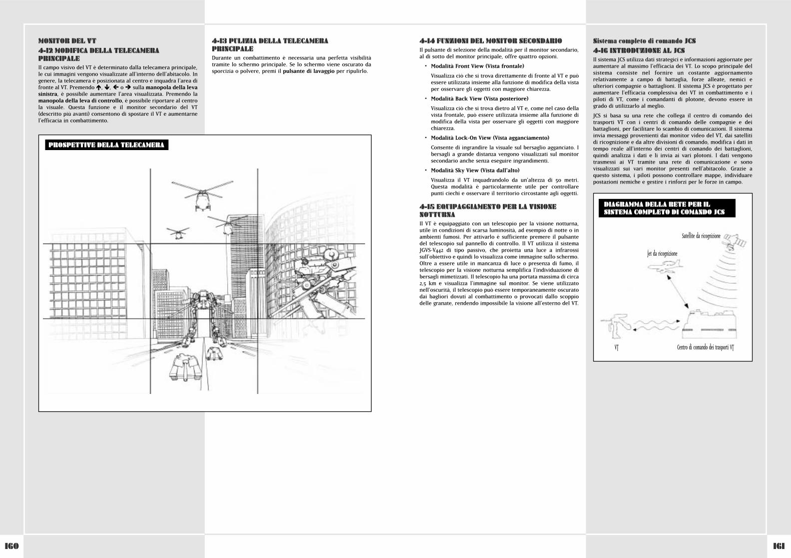
161160
MONITOR DEL VT4-12 MODIFICA DELLA TELECAMERAPRINCIPALEIl campo visivo del VT è determinato dalla telecamera principale,le cui immagini vengono visualizzate all'interno dell'abitacolo. Ingenere, la telecamera è posizionata al centro e inquadra l'area difronte al VT. Premendo �, �, � o � sulla manopola della levasinistra, è possibile aumentare l'area visualizzata. Premendo lamanopola della leva di controllo, è possibile riportare al centrola visuale. Questa funzione e il monitor secondario del VT(descritto più avanti) consentono di spostare il VT e aumentarnel'efficacia in combattimento.
4-13 PULIZIA DELLA TELECAMERAPRINCIPALEDurante un combattimento è necessaria una perfetta visibilitàtramite lo schermo principale. Se lo schermo viene oscurato dasporcizia o polvere, premi il pulsante di lavaggio per ripulirlo.
PROSPETTIVE DELLA TELECAMERA
4-14 FUNZIONI DEL MONITOR SECONDARIOIl pulsante di selezione della modalità per il monitor secondario,al di sotto del monitor principale, offre quattro opzioni.
• Modalità Front View (Vista frontale)
Visualizza ciò che si trova direttamente di fronte al VT e puòessere utilizzata insieme alla funzione di modifica della vistaper osservare gli oggetti con maggiore chiarezza.
• Modalità Back View (Vista posteriore)
Visualizza ciò che si trova dietro al VT e, come nel caso dellavista frontale, può essere utilizzata insieme alla funzione dimodifica della vista per osservare gli oggetti con maggiorechiarezza.
• Modalità Lock-On View (Vista agganciamento)
Consente di ingrandire la visuale sul bersaglio agganciato. Ibersagli a grande distanza vengono visualizzati sul monitorsecondario anche senza eseguire ingrandimenti.
• Modalità Sky View (Vista dall'alto)
Visualizza il VT inquadrandolo da un'altezza di 50 metri.Questa modalità è particolarmente utile per controllarepunti ciechi e osservare il territorio circostante agli oggetti.
4-15 EQUIPAGGIAMENTO PER LA VISIONENOTTURNAIl VT è equipaggiato con un telescopio per la visione notturna,utile in condizioni di scarsa luminosità, ad esempio di notte o inambienti fumosi. Per attivarlo è sufficiente premere il pulsantedel telescopio sul pannello di controllo. Il VT utilizza il sistemaJGVS-V442 di tipo passivo, che proietta una luce a infrarossisull'obiettivo e quindi lo visualizza come immagine sullo schermo.Oltre a essere utile in mancanza di luce o presenza di fumo, iltelescopio per la visione notturna semplifica l'individuazione dibersagli mimetizzati. Il telescopio ha una portata massima di circa2,5 km e visualizza l'immagine sul monitor. Se viene utilizzatonell'oscurità, il telescopio può essere temporaneamente oscuratodai bagliori dovuti al combattimento o provocati dallo scoppiodelle granate, rendendo impossibile la visione all'esterno del VT.
Sistema completo di comando JCS4-16 INTRODUZIONE AL JCSIl sistema JCS utilizza dati strategici e informazioni aggiornate peraumentare al massimo l'efficacia dei VT. Lo scopo principale delsistema consiste nel fornire un costante aggiornamentorelativamente a campo di battaglia, forze alleate, nemici eulteriori compagnie o battaglioni. Il sistema JCS è progettato peraumentare l'efficacia complessiva dei VT in combattimento e ipiloti di VT, come i comandanti di plotone, devono essere ingrado di utilizzarlo al meglio.
JCS si basa su una rete che collega il centro di comando deitrasporti VT con i centri di comando delle compagnie e deibattaglioni, per facilitare lo scambio di comunicazioni. Il sistemainvia messaggi provenienti dai monitor video del VT, dai satellitidi ricognizione e da altre divisioni di comando, modifica i dati intempo reale all'interno dei centri di comando dei battaglioni,quindi analizza i dati e li invia ai vari plotoni. I dati vengonotrasmessi ai VT tramite una rete di comunicazione e sonovisualizzati sui vari monitor presenti nell'abitacolo. Grazie aquesto sistema, i piloti possono controllare mappe, individuarepostazioni nemiche e gestire i rinforzi per le forze in campo.
DIAGRAMMA DELLA RETE PER ILSISTEMA COMPLETO DI COMANDO JCS
Centro di comando dei trasporti VTVT
Jet da ricognizione
Satellite da ricognizione
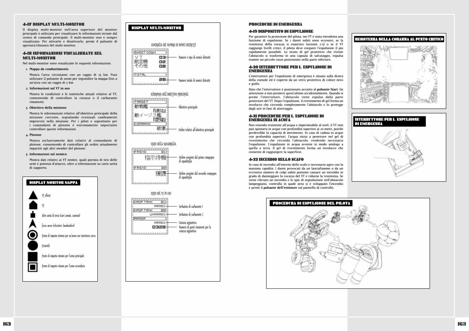
163162
4-17 DISPLAY MULTI-MONITORIl display multi-monitor nell'area superiore del monitorprincipale è utilizzato per visualizzare le informazioni inviate dalcentro di comando principale. Il multi-monitor non è semprevisualizzato. Per attivarlo e disattivarlo, premi il pulsante diapertura/chiusura del multi-monitor.
4-18 INFORMAZIONI VISUALIZZATE NELMULTI-MONITORNel multi-monitor sono visualizzate le seguenti informazioni.
1. Mappa da combattimento
Mostra l'area circostante con un raggio di 25 km. Puoiutilizzare il pulsante di zoom per ingrandire la mappa fino aun'area con un raggio di 5 km.
2. Informazioni sul VT in uso
Mostra le condizioni e le statistiche attuali relative al VT,consentendo di controllare la corazza o il carburanterimanenti.
3. Obiettivo della missione
Mostra le informazioni relative all'obiettivo principale dellamissione corrente, segnalando eventuali cambiamentiimprovvisi nella missione. Per i piloti e soprattutto per i comandanti di plotone è estremamente importantecontrollare queste informazioni.
4. Plotone
Mostra esclusivamente dati relativi al comandante diplotone, consentendo di controllare gli ordini attualmenteimpartiti agli altri membri del plotone.
5. Informazioni sul nemico
Mostra dati relativi ai VT nemici, quali portata di tiro dellearmi e potenza d'attacco, oltre a informazioni su varie unitàdi supporto.
DISPLAY MONITOR MAPPA
DISPLAY MULTI-MONITOR
CONTROLLO DEL NUMERO DI NEMICI DISTRUTTI
Numero e tipo di nemici distrutti
Numero totale di nemici distrutti
Obiettivo principale
Ordini relativi all'obiettivo principale
SCHERMATA DELL'OBIETTIVO PRINCIPALE
Ordine eseguito dal primo compagno di squadriglia
Ordine eseguito dal secondo compagnodi squadriglia
STATO DELLA SQUADRIGLIA
Serbatoio di carburante 1
Serbatoio di carburante 2
Corazza aggiuntivaNumero di punti rimanenti per lacorazza aggiuntiva
STATO DEL VT IN USOVT alleati
VT
Altre unità di terra (carri armati, cannoni)
Forze aeree (elicotteri, bombardieri)
Punto di impatto stimato per un'arma con traiettoria curva
Proiettili
Punto di impatto stimato per l'arma principale
Punto di impatto stimato per l'arma secondaria
PROCEDURE DI EMERGENZA
4-19 DISPOSITIVO DI ESPULSIONEPer garantire la protezione del pilota, nei VT è stata introdotta unafunzione di espulsione. Se i danni subiti sono eccessivi, se laresistenza della corazza si esaurisce (sezione 2-5) o se il VTraggiunge livelli critici, il pilota deve eseguire l'espulsione il piùrapidamente possibile. Lo strato di gel protettivo che rivestel'abitacolo si trasforma in una capsula di salvataggio, espulsatramite un piccolo razzo posizionato nella parte inferiore.
4-20 INTERRUTTORE PER L´ ESPULSIONE DIEMERGENZAL'interruttore per l'espulsione di emergenza è situato sulla destradella console ed è coperto da un vetro protettivo di colore nero e giallo.
Dato che l'interruttore è posizionato accanto al pulsante Start, faiattenzione a non premere quest'ultimo accidentalmente. Quando sipreme l'interruttore, l'abitacolo viene espulso dalla parteposteriore del VT. Dopo l'espulsione, il rivestimento di gel forma uninvolucro che circonda completamente l'abitacolo e lo proteggedagli urti in fase di atterraggio.
4-21 PROCEDURE PER L ´ESPULSIONE DIEMERGENZA IN ACQUANon essendo resistente all'acqua e impermeabile al 100%, il VT nonpuò spostarsi in acque con profondità superiori ai 20 metri, poichéperderebbe la capacità di movimento. In caso di caduta in acquecon profondità superiori, l'acqua inizia a penetrare nel gel dirivestimento che circonda l'abitacolo, rendendo necessarial'espulsione. L'espulsione in acqua avviene in modo analogo aquella a terra. Il gel di rivestimento forma un involucro checonsente di raggiungere la superficie.
4-22 INCENDIO NELLO SCAFOIn caso di incendio all'interno dello scafo è necessario agire con lamassima rapidità. I danni provocati da un lanciafiamme o da uneccessivo numero di colpi subiti possono causare un incendio ingrado di danneggiare la corazza del VT e ridurne la resistenza. Seviene rilevato un incendio e le spie di segnalazione nell'abitacololampeggiano, controlla in quale area si è sviluppato l'incendio e premi il pulsante dell'estintore sul pannello di controllo.
PROCEDURA DI ESPULSIONE DEL PILOTA
INTERRUTTORE PER L ´ESPULSIONE DI EMERGENZA
RESISTENZA DELLA CORAZZA AL PUNTO CRITICO
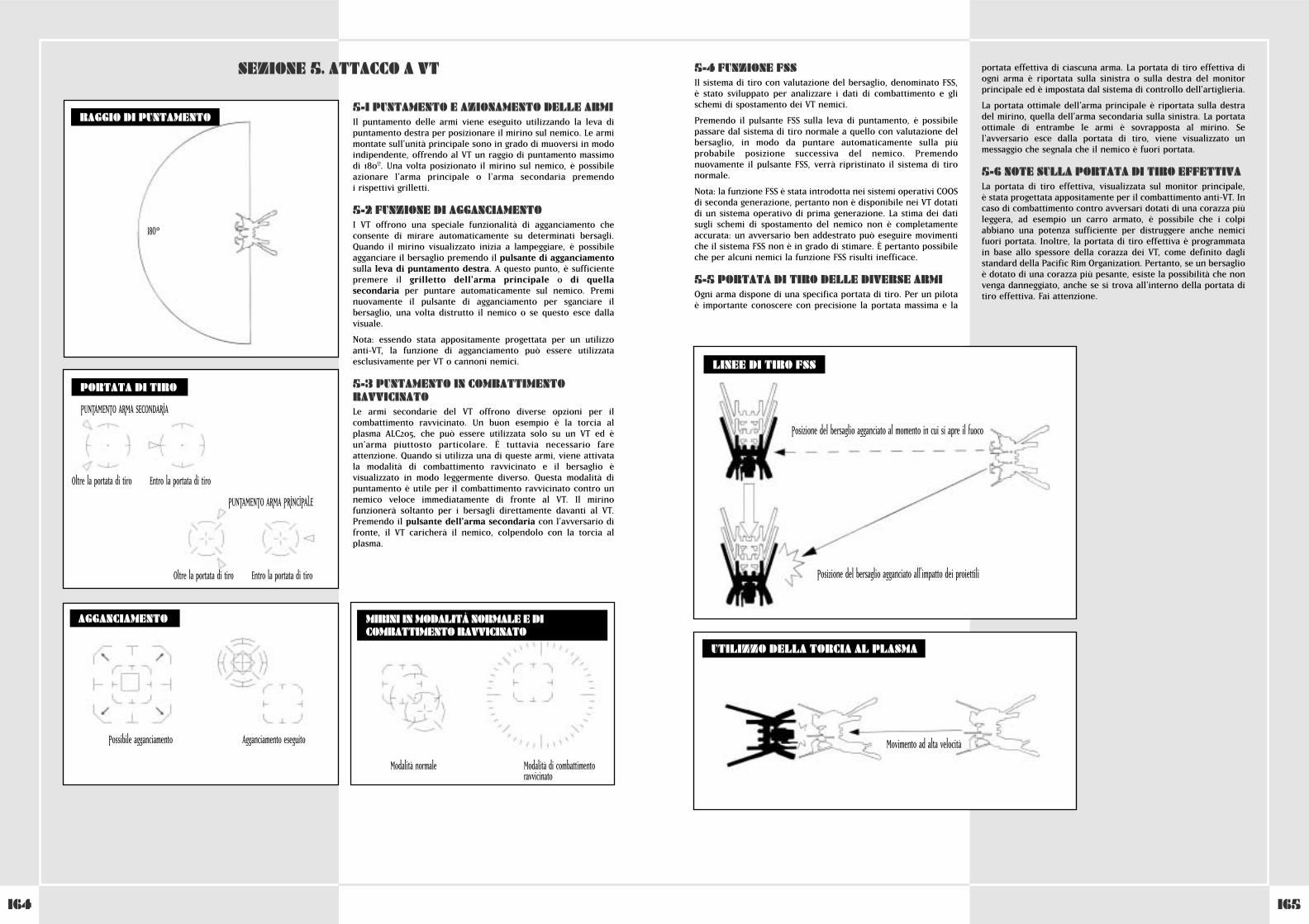
165164
5-1 PUNTAMENTO E AZIONAMENTO DELLE ARMIIl puntamento delle armi viene eseguito utilizzando la leva dipuntamento destra per posizionare il mirino sul nemico. Le armimontate sull'unità principale sono in grado di muoversi in modoindipendente, offrendo al VT un raggio di puntamento massimodi 180ºº. Una volta posizionato il mirino sul nemico, è possibileazionare l'arma principale o l'arma secondaria premendo i rispettivi grilletti.
5-2 FUNZIONE DI AGGANCIAMENTOI VT offrono una speciale funzionalità di agganciamento checonsente di mirare automaticamente su determinati bersagli.Quando il mirino visualizzato inizia a lampeggiare, è possibileagganciare il bersaglio premendo il pulsante di agganciamentosulla leva di puntamento destra. A questo punto, è sufficientepremere il grilletto dell'arma principale o di quellasecondaria per puntare automaticamente sul nemico. Preminuovamente il pulsante di agganciamento per sganciare ilbersaglio, una volta distrutto il nemico o se questo esce dallavisuale.
Nota: essendo stata appositamente progettata per un utilizzoanti-VT, la funzione di agganciamento può essere utilizzataesclusivamente per VT o cannoni nemici.
5-3 PUNTAMENTO IN COMBATTIMENTORAVVICINATOLe armi secondarie del VT offrono diverse opzioni per ilcombattimento ravvicinato. Un buon esempio è la torcia alplasma ALC205, che può essere utilizzata solo su un VT ed èun'arma piuttosto particolare. È tuttavia necessario fareattenzione. Quando si utilizza una di queste armi, viene attivatala modalità di combattimento ravvicinato e il bersaglio èvisualizzato in modo leggermente diverso. Questa modalità dipuntamento è utile per il combattimento ravvicinato contro unnemico veloce immediatamente di fronte al VT. Il mirinofunzionerà soltanto per i bersagli direttamente davanti al VT.Premendo il pulsante dell'arma secondaria con l'avversario difronte, il VT caricherà il nemico, colpendolo con la torcia alplasma.
SEZIONE 5. ATTACCO A VT
AGGANCIAMENTO
RAGGIO DI PUNTAMENTO
PORTATA DI TIRO
180°
PUNTAMENTO ARMA SECONDARIA
Oltre la portata di tiro Entro la portata di tiro
PUNTAMENTO ARMA PRINCIPALE
Oltre la portata di tiro Entro la portata di tiro
Possibile agganciamento Agganciamento eseguito
MIRINI IN MODALITÀ NORMALE E DICOMBATTIMENTO RAVVICINATO
Modalità normale Modalità di combattimentoravvicinato
5-4 FUNZIONE FSSIl sistema di tiro con valutazione del bersaglio, denominato FSS, è stato sviluppato per analizzare i dati di combattimento e glischemi di spostamento dei VT nemici.
Premendo il pulsante FSS sulla leva di puntamento, è possibilepassare dal sistema di tiro normale a quello con valutazione delbersaglio, in modo da puntare automaticamente sulla piùprobabile posizione successiva del nemico. Premendonuovamente il pulsante FSS, verrà ripristinato il sistema di tironormale.
Nota: la funzione FSS è stata introdotta nei sistemi operativi COOSdi seconda generazione, pertanto non è disponibile nei VT dotatidi un sistema operativo di prima generazione. La stima dei datisugli schemi di spostamento del nemico non è completamenteaccurata: un avversario ben addestrato può eseguire movimentiche il sistema FSS non è in grado di stimare. È pertanto possibileche per alcuni nemici la funzione FSS risulti inefficace.
5-5 PORTATA DI TIRO DELLE DIVERSE ARMIOgni arma dispone di una specifica portata di tiro. Per un pilota è importante conoscere con precisione la portata massima e la
portata effettiva di ciascuna arma. La portata di tiro effettiva diogni arma è riportata sulla sinistra o sulla destra del monitorprincipale ed è impostata dal sistema di controllo dell'artiglieria.
La portata ottimale dell'arma principale è riportata sulla destradel mirino, quella dell'arma secondaria sulla sinistra. La portataottimale di entrambe le armi è sovrapposta al mirino. Sel'avversario esce dalla portata di tiro, viene visualizzato unmessaggio che segnala che il nemico è fuori portata.
5-6 NOTE SULLA PORTATA DI TIRO EFFETTIVALa portata di tiro effettiva, visualizzata sul monitor principale, è stata progettata appositamente per il combattimento anti-VT. Incaso di combattimento contro avversari dotati di una corazza piùleggera, ad esempio un carro armato, è possibile che i colpiabbiano una potenza sufficiente per distruggere anche nemicifuori portata. Inoltre, la portata di tiro effettiva è programmatain base allo spessore della corazza dei VT, come definito daglistandard della Pacific Rim Organization. Pertanto, se un bersaglioè dotato di una corazza più pesante, esiste la possibilità che nonvenga danneggiato, anche se si trova all'interno della portata ditiro effettiva. Fai attenzione.
UTILIZZO DELLA TORCIA AL PLASMA
Movimento ad alta velocità
LINEE DI TIRO FSS
Posizione del bersaglio agganciato al momento in cui si apre il fuoco
Posizione del bersaglio agganciato all'impatto dei proiettili
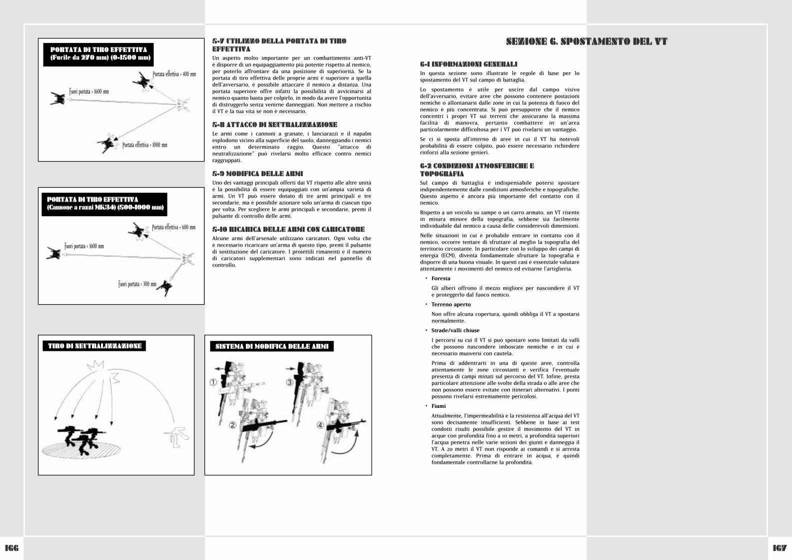
167166
5-7 UTILIZZO DELLA PORTATA DI TIROEFFETTIVAUn aspetto molto importante per un combattimento anti-VT è disporre di un equipaggiamento più potente rispetto al nemico,per poterlo affrontare da una posizione di superiorità. Se laportata di tiro effettiva delle proprie armi è superiore a quelladell'avversario, è possibile attaccare il nemico a distanza. Unaportata superiore offre infatti la possibilità di avvicinarsi alnemico quanto basta per colpirlo, in modo da avere l'opportunitàdi distruggerlo senza venirne danneggiati. Non mettere a rischioil VT e la tua vita se non è necessario.
5-8 ATTACCO DI NEUTRALIZZAZIONE Le armi come i cannoni a granate, i lanciarazzi e il napalmesplodono vicino alla superficie del suolo, danneggiando i nemicientro un determinato raggio. Questo "attacco dineutralizzazione" può rivelarsi molto efficace contro nemiciraggruppati.
5-9 MODIFICA DELLE ARMIUno dei vantaggi principali offerti dai VT rispetto alle altre unità è la possibilità di essere equipaggiati con un'ampia varietà diarmi. Un VT può essere dotato di tre armi principali e tresecondarie, ma è possibile azionare solo un'arma di ciascun tipoper volta. Per scegliere le armi principali e secondarie, premi ilpulsante di controllo delle armi.
5-10 RICARICA DELLE ARMI CON CARICATOREAlcune armi dell'arsenale utilizzano caricatori. Ogni volta che è necessario ricaricare un'arma di questo tipo, premi il pulsantedi sostituzione del caricatore. I proiettili rimanenti e il numerodi caricatori supplementari sono indicati nel pannello dicontrollo.
SISTEMA DI MODIFICA DELLE ARMITIRO DI NEUTRALIZZAZIONE
Portata effettiva = 400 mm
Portata effettiva = 1000 mm
Fuori portata = 1600 mm
PORTATA DI TIRO EFFETTIVA(Fucile da 270 mm) (0-1500 mm)
PORTATA DI TIRO EFFETTIVA(Cannone a razzi MK34) (500-1000 mm)
Portata effettiva = 600 mm
Fuori portata = 1600 mm
Fuori portata = 300 mm
6-1 INFORMAZIONI GENERALIIn questa sezione sono illustrate le regole di base per lospostamento del VT sul campo di battaglia.
Lo spostamento è utile per uscire dal campo visivodell'avversario, evitare aree che possono contenere postazioninemiche o allontanarsi dalle zone in cui la potenza di fuoco delnemico è più concentrata. Si può presupporre che il nemicoconcentri i propri VT sui terreni che assicurano la massimafacilità di manovra, pertanto combattere in un'areaparticolarmente difficoltosa per i VT può rivelarsi un vantaggio.
Se ci si sposta all'interno di aree in cui il VT ha notevoliprobabilità di essere colpito, può essere necessario richiedererinforzi alla sezione genieri.
6-2 CONDIZIONI ATMOSFERICHE ETOPOGRAFIASul campo di battaglia è indispensabile potersi spostareindipendentemente dalle condizioni atmosferiche e topografiche.Questo aspetto è ancora più importante del contatto con ilnemico.
Rispetto a un veicolo su zampe o un carro armato, un VT risentein misura minore della topografia, sebbene sia facilmenteindividuabile dal nemico a causa delle considerevoli dimensioni.
Nelle situazioni in cui è probabile entrare in contatto con ilnemico, occorre tentare di sfruttare al meglio la topografia delterritorio circostante. In particolare con lo sviluppo dei campi dienergia (ECM), diventa fondamentale sfruttare la topografia edisporre di una buona visuale. In questi casi è essenziale valutareattentamente i movimenti del nemico ed evitarne l'artiglieria.
• Foresta
Gli alberi offrono il mezzo migliore per nascondere il VT e proteggerlo dal fuoco nemico.
• Terreno aperto
Non offre alcuna copertura, quindi obbliga il VT a spostarsinormalmente.
• Strade/valli chiuse
I percorsi su cui il VT si può spostare sono limitati da valliche possono nascondere imboscate nemiche e in cui ènecessario muoversi con cautela.
Prima di addentrarti in una di queste aree, controllaattentamente le zone circostanti e verifica l'eventualepresenza di campi minati sul percorso del VT. Infine, prestaparticolare attenzione alle svolte della strada o alle aree chenon possono essere evitate con itinerari alternativi. I pontipossono rivelarsi estremamente pericolosi.
• Fiumi
Attualmente, l'impermeabilità e la resistenza all'acqua del VTsono decisamente insufficienti. Sebbene in base ai testcondotti risulti possibile gestire il movimento del VT inacque con profondità fino a 10 metri, a profondità superioril'acqua penetra nelle varie sezioni dei giunti e danneggia ilVT. A 20 metri il VT non risponde ai comandi e si arrestacompletamente. Prima di entrare in acqua, è quindifondamentale controllarne la profondità.
SEZIONE 6. SPOSTAMENTO DEL VT

169168
CONFIGURAZIONE DEL CONTROLLER STEEL BATTALION
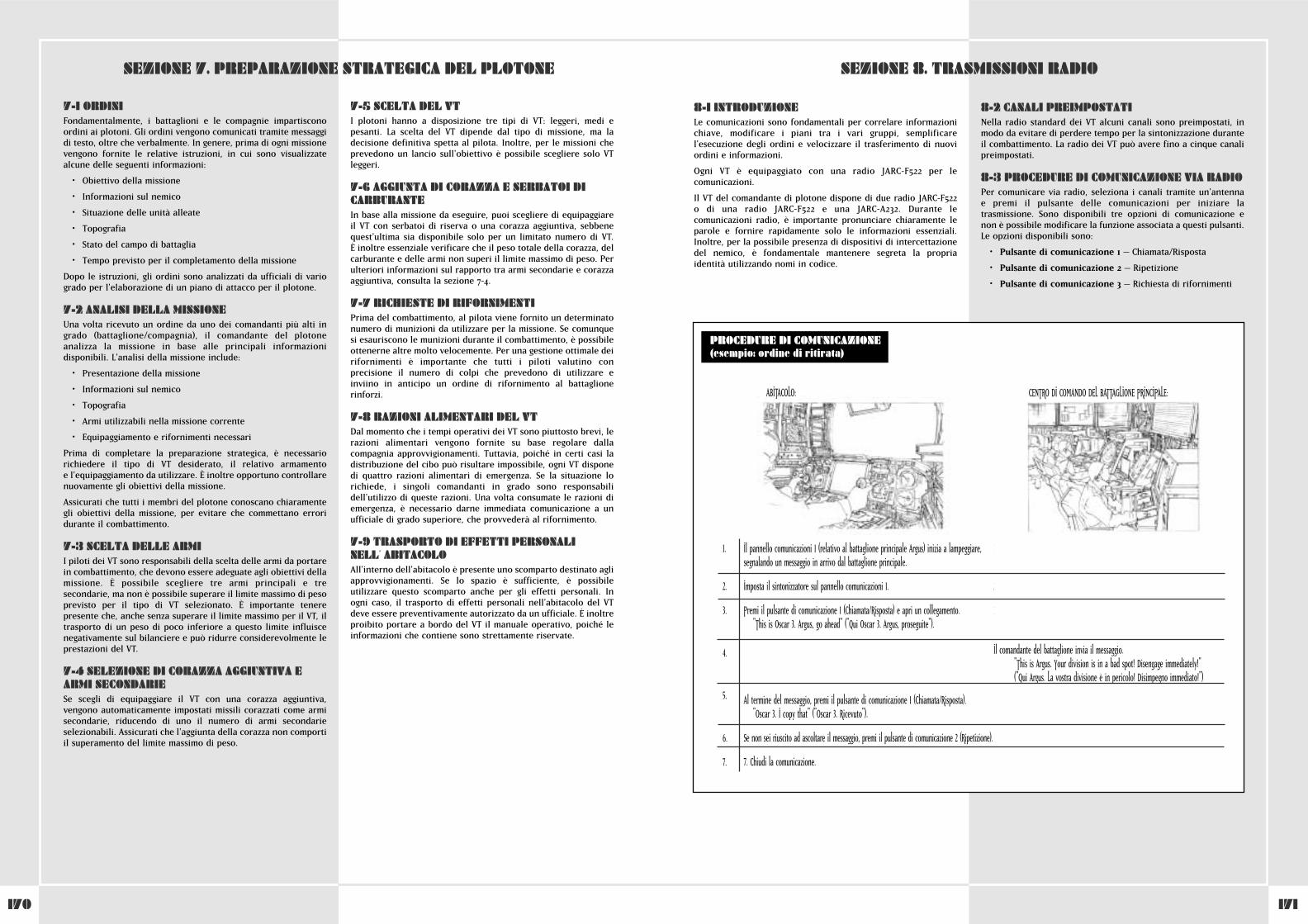
171170
8-1 INTRODUZIONELe comunicazioni sono fondamentali per correlare informazionichiave, modificare i piani tra i vari gruppi, semplificarel'esecuzione degli ordini e velocizzare il trasferimento di nuoviordini e informazioni.
Ogni VT è equipaggiato con una radio JARC-F522 per lecomunicazioni.
Il VT del comandante di plotone dispone di due radio JARC-F522o di una radio JARC-F522 e una JARC-A232. Durante lecomunicazioni radio, è importante pronunciare chiaramente leparole e fornire rapidamente solo le informazioni essenziali.Inoltre, per la possibile presenza di dispositivi di intercettazionedel nemico, è fondamentale mantenere segreta la propriaidentità utilizzando nomi in codice.
8-2 CANALI PREIMPOSTATINella radio standard dei VT alcuni canali sono preimpostati, inmodo da evitare di perdere tempo per la sintonizzazione duranteil combattimento. La radio dei VT può avere fino a cinque canalipreimpostati.
8-3 PROCEDURE DI COMUNICAZIONE VIA RADIOPer comunicare via radio, seleziona i canali tramite un'antenna e premi il pulsante delle comunicazioni per iniziare latrasmissione. Sono disponibili tre opzioni di comunicazione enon è possibile modificare la funzione associata a questi pulsanti.Le opzioni disponibili sono:
• Pulsante di comunicazione 1 – Chiamata/Risposta
• Pulsante di comunicazione 2 – Ripetizione
• Pulsante di comunicazione 3 – Richiesta di rifornimenti
SEZIONE 8. TRASMISSIONI RADIO
1. Communication panel 1 (from the main battalion Argus) begins to flash. This signalsthat a message from the main battalion is coming in.
2. Set the tuner on Communications Panel 1.
3. Press Communication Button 1 (respond/call) and open a connection.
"This is Oscar 3. Argus, go ahead."
Il comandante del battaglione invia il messaggio."This is Argus. Your division is in a bad spot! Disengage immediately!" ("Qui Argus. La vostra divisione è in pericolo! Disimpegno immediato!")
5. After you hear what was said, press Communication Button 1 (respond/call).
"Oscar 3. I copy that."
6. Finish the communication.
7. If you didn’t hear the message, press Communication Button 2 (repeat).
PROCEDURE DI COMUNICAZIONE(esempio: ordine di ritirata)
ABITACOLO: CENTRO DI COMANDO DEL BATTAGLIONE PRINCIPALE:
1. Communication panel 1 (from the main battalion Argus) begins to flash.This signals that a message from the main battalion is coming in.
2. Set the tuner on Communications Panel 1.
3. Press Communication Button 1 (respond/call) and open a connection.
"This is Oscar 3. Argus, go ahead."
4. The battalion head gives his message.
"This is Argus. Your division is in a bad spot! Retreat immediately!"
5. After you hear what was said, press Communication Button 1 "
6. If you didn’t hear the message, press Communication Button 2 (repeat).
7. Finish the communication.
Il pannello comunicazioni 1 (relativo al battaglione principale Argus) inizia a lampeggiare,segnalando un messaggio in arrivo dal battaglione principale.
Imposta il sintonizzatore sul pannello comunicazioni 1.
Premi il pulsante di comunicazione 1 (Chiamata/Risposta) e apri un collegamento. "This is Oscar 3. Argus, go ahead" ("Qui Oscar 3. Argus, proseguite").
4. The battalion head gives his message.
"This is Argus. Your division is in a bad spot! Retreat immediately!"
Al termine del messaggio, premi il pulsante di comunicazione 1 (Chiamata/Risposta). "Oscar 3. I copy that" ("Oscar 3. Ricevuto").
Se non sei riuscito ad ascoltare il messaggio, premi il pulsante di comunicazione 2 (Ripetizione).
7. Chiudi la comunicazione.
7-1 ORDINIFondamentalmente, i battaglioni e le compagnie impartisconoordini ai plotoni. Gli ordini vengono comunicati tramite messaggidi testo, oltre che verbalmente. In genere, prima di ogni missionevengono fornite le relative istruzioni, in cui sono visualizzatealcune delle seguenti informazioni:
• Obiettivo della missione
• Informazioni sul nemico
• Situazione delle unità alleate
• Topografia
• Stato del campo di battaglia
• Tempo previsto per il completamento della missione
Dopo le istruzioni, gli ordini sono analizzati da ufficiali di variogrado per l'elaborazione di un piano di attacco per il plotone.
7-2 ANALISI DELLA MISSIONEUna volta ricevuto un ordine da uno dei comandanti più alti ingrado (battaglione/compagnia), il comandante del plotoneanalizza la missione in base alle principali informazionidisponibili. L'analisi della missione include:
• Presentazione della missione
• Informazioni sul nemico
• Topografia
• Armi utilizzabili nella missione corrente
• Equipaggiamento e rifornimenti necessari
Prima di completare la preparazione strategica, è necessariorichiedere il tipo di VT desiderato, il relativo armamento e l'equipaggiamento da utilizzare. È inoltre opportuno controllarenuovamente gli obiettivi della missione.
Assicurati che tutti i membri del plotone conoscano chiaramentegli obiettivi della missione, per evitare che commettano erroridurante il combattimento.
7-3 SCELTA DELLE ARMII piloti dei VT sono responsabili della scelta delle armi da portarein combattimento, che devono essere adeguate agli obiettivi dellamissione. È possibile scegliere tre armi principali e tresecondarie, ma non è possibile superare il limite massimo di pesoprevisto per il tipo di VT selezionato. È importante tenerepresente che, anche senza superare il limite massimo per il VT, iltrasporto di un peso di poco inferiore a questo limite influiscenegativamente sul bilanciere e può ridurre considerevolmente leprestazioni del VT.
7-4 SELEZIONE DI CORAZZA AGGIUNTIVA EARMI SECONDARIESe scegli di equipaggiare il VT con una corazza aggiuntiva,vengono automaticamente impostati missili corazzati come armisecondarie, riducendo di uno il numero di armi secondarieselezionabili. Assicurati che l'aggiunta della corazza non comportiil superamento del limite massimo di peso.
7-5 SCELTA DEL VTI plotoni hanno a disposizione tre tipi di VT: leggeri, medi epesanti. La scelta del VT dipende dal tipo di missione, ma ladecisione definitiva spetta al pilota. Inoltre, per le missioni cheprevedono un lancio sull'obiettivo è possibile scegliere solo VTleggeri.
7-6 AGGIUNTA DI CORAZZA E SERBATOI DICARBURANTEIn base alla missione da eseguire, puoi scegliere di equipaggiareil VT con serbatoi di riserva o una corazza aggiuntiva, sebbenequest'ultima sia disponibile solo per un limitato numero di VT. È inoltre essenziale verificare che il peso totale della corazza, delcarburante e delle armi non superi il limite massimo di peso. Perulteriori informazioni sul rapporto tra armi secondarie e corazzaaggiuntiva, consulta la sezione 7-4.
7-7 RICHIESTE DI RIFORNIMENTIPrima del combattimento, al pilota viene fornito un determinatonumero di munizioni da utilizzare per la missione. Se comunquesi esauriscono le munizioni durante il combattimento, è possibileottenerne altre molto velocemente. Per una gestione ottimale deirifornimenti è importante che tutti i piloti valutino conprecisione il numero di colpi che prevedono di utilizzare einviino in anticipo un ordine di rifornimento al battaglionerinforzi.
7-8 RAZIONI ALIMENTARI DEL VTDal momento che i tempi operativi dei VT sono piuttosto brevi, lerazioni alimentari vengono fornite su base regolare dallacompagnia approvvigionamenti. Tuttavia, poiché in certi casi ladistribuzione del cibo può risultare impossibile, ogni VT disponedi quattro razioni alimentari di emergenza. Se la situazione lorichiede, i singoli comandanti in grado sono responsabilidell'utilizzo di queste razioni. Una volta consumate le razioni diemergenza, è necessario darne immediata comunicazione a unufficiale di grado superiore, che provvederà al rifornimento.
7-9 TRASPORTO DI EFFETTI PERSONALINELL´ ABITACOLOAll'interno dell'abitacolo è presente uno scomparto destinato agliapprovvigionamenti. Se lo spazio è sufficiente, è possibileutilizzare questo scomparto anche per gli effetti personali. Inogni caso, il trasporto di effetti personali nell'abitacolo del VTdeve essere preventivamente autorizzato da un ufficiale. È inoltreproibito portare a bordo del VT il manuale operativo, poiché leinformazioni che contiene sono strettamente riservate.
SEZIONE 7. PREPARAZIONE STRATEGICA DEL PLOTONE

173172
9-1 RICEZIONE DI RIFORNIMENTIPoiché i rifornimenti sono necessari per il mantenimentodell'efficienza del VT, è indispensabile individuare un luogo in cuiriceverli durante il combattimento. Ricevere i rifornimenti incombattimento è un'operazione da eseguire regolarmente, macomunque rischiosa. È preferibile ricevere i rifornimenti solo dinotte o con un'adeguata copertura. I rifornimenti destinati ai VTsono trasportati da un elicottero controllato dal Battaglionerifornimenti della Divisione rinforzi. Oltre a carburante emunizioni, l'elicottero di rifornimento può trasportare corazzenuove, aggiuntive o parti di ricambio per il VT. Per ottimizzare leoperazioni, assicurati di inviare una richiesta con la previsionedei rifornimenti necessari prima di iniziare la missione.
9-2 CLASSIFICAZIONE DEI RIFORNIMENTIPer semplificarne il trasporto, i rifornimenti sono suddivisi incinque gruppi principali. Con poche eccezioni, la maggior partedei rifornimenti richiesti prima di un combattimento rientra inuno dei tre gruppi riportati di seguito.
Questi rifornimenti sono forniti con un unico ordine a ogni VT.
1. Rifornimenti di tipo 1: razioni alimentari
2. Rifornimenti di tipo 3: liquidi (olio, carburante, lubrificanti)
3. Rifornimenti di tipo 5: munizioni di vario genere
Prima di iniziare il combattimento, ogni pilota deve preparare unelenco dei rifornimenti necessari e sottoporlo all'approvazionedel proprio ufficiale in comando.
9-3 RIFORNIMENTI TRAMITE ELICOTTERODurante il combattimento, i rifornimenti destinati ai VT vengonotrasportati da un elicottero controllato dal battaglionerifornimenti della divisione rinforzi. Quando riceve una richiestadi rifornimento, l'elicottero si dirige verso la posizione in cui sitrova il VT e, una volta giunto a destinazione, resta in volostazionario. Il pilota deve portare il VT al di sotto dell'elicotteroper consentire il trasferimento di carburante, munizioni, nuovecorazze e ricambi per il VT.
9-4 PRECAUZIONI DURANTE LA RICEZIONE DEIRIFORNIMENTIL'operazione di rifornimento, che richiede un determinatoperiodo di tempo, espone sia il VT che l'elicottero agli attacchidel nemico. Per evitare attacchi, è necessario esaminare conestrema attenzione il territorio circostante e ricevere irifornimenti in un punto con una copertura sufficiente e pochinemici visibili. Queste precauzioni sono essenziali per evitare chel'elicottero venga abbattuto prima del completamentodell'operazione di rifornimento.
9-5 CREAZIONE DI UN CENTRO DIRIFORNIMENTOPuò accadere che, a causa delle circostanze del combattimento odelle condizioni atmosferiche, l'elicottero non sia in grado diconsegnare i rifornimenti. Per risolvere questo problema, èpossibile creare un centro di rifornimento dietro le linee delleforze alleate. Il punto in cui è situato il centro di rifornimento èstabilito prima del combattimento, in base ai seguenti criteri:
1. Disponibilità di spazio sufficiente per l'immagazzinaggio deirifornimenti necessari.
2. Disponibilità di un percorso di collegamento protetto tra laprima linea e la retroguardia.
3. Copertura dagli avvistamenti nemici.
4. Copertura dal fuoco nemico.
Il centro di rifornimento può essere situato solo in un punto incui la prima linea è già stabilita ed è presente un accampamentoche garantisce la copertura dell'area. Fondamentalmente,rappresenta un'eccezione.
Ogni volta che è possibile, i piloti di VT sono tenuti a eseguire irifornimenti di carburante utilizzando l'elicottero di rifornimento.s
SEZIONE 9. RIFORNIMENTI
DIAGRAMMA DI UN ELICOTTERO DI RIFORNIMENTO PER VT
Volo normale
Possibile rifornimento
8-4 INVIO DI UN MESSAGGIO1. Scegli la persona da contattare impostando il
canale corrispondente sul sintonizzatore.
2. Premi il pulsante di comunicazione 1(Chiamata/Risposta) per inviare la chiamata.
3. Risponderà la persona desiderata.
4. Dopo avere verificato l'identità della personache ha risposto, invia la tua richiesta.
5. Il destinatario della chiamata controllerà larichiesta.
6. La comunicazione verrà terminata.
8-5 RICEZIONE DI UN MESSAGGIO1. Quando è in arrivo un messaggio, il pannello di
comunicazione inizia a lampeggiare. Imposta ilsintonizzatore sul canale lampeggiante in mododa ascoltare il messaggio in arrivo.
2. Premi il pulsante di comunicazione 1 (Chiamata/Risposta) e rispondi alla chiamata.
3. L'interlocutore visualizzerà la tua risposta ecomunicherà il messaggio.
4. Dopo avere ascoltato il messaggio, premi ilpulsante di comunicazione 1 (Chiamata/Risposta) per chiudere la comunicazione.
8-6 RIPETIZIONE DI UN MESSAGGIOSe non riesci a comprendere un messaggio ricevuto,premi il pulsante di comunicazione 2 per chiedereall'interlocutore di ripeterlo. Questa richiesta puòessere inviata fino a quando il pannello dicomunicazione lampeggia, indicando che le lineesono aperte. Premendo il pulsante di comunicazione1, la comunicazione verrà terminata, chiudendo lalinea.
IMPOSTAZIONI DEI CANALI PER IL PANNELLO COMUNICAZIONI
Pannello comunicazioni 1 Pannello comunicazioni 2 Pannello comunicazioni 3 Pannello comunicazioni 4 Pannello comunicazioni 5
MIS00
MIS01
MIS02
MIS03 Comando Rifornimenti Comandante di VT
MIS04 Comando Rifornimenti Comandante di VT
MIS05 Comando Rifornimenti Comandante di VT
MIS06 Comando Rifornimenti Comandante di VT
MIS07 Comando Rifornimenti Comandante di VT
MIS08 Comando Rifornimenti Comandante di VT
MIS09 Comando Rifornimenti Comandante di VT
MIS10 Comando Rifornimenti Comandante di VT
MIS11 Comando Rifornimenti Comandante di VT
MIS12 Comando Rifornimenti Compagno 1 Compagno 2 Compagno 1/2
MIS13 Comando Rifornimenti Compagno 1 Compagno 2 Compagno 1/2
MIS14 Comando Rifornimenti Compagno 1 Compagno 2 Compagno 1/2
MIS15 Comando Rifornimenti Compagno 1 Compagno 2 Compagno 1/2
MIS16 Comando Rifornimenti Compagno 1 Compagno 2 Compagno 1/2
MIS17 Comando Rifornimenti Divisione spionaggio
MIS18 Comando Rifornimenti Compagno 1 Compagno 2 Compagno 1/2
MIS19 Comando Rifornimenti Compagno 1 Compagno 2 Compagno 1/2
MIS20 Comando Rifornimenti
MIS21 Comando Rifornimenti Compagno 1 Compagno 2 Compagno 1/2
MIS22 Comando Rifornimenti Compagno 1 Compagno 2 Compagno 1/2
MIS23 Comando Rifornimenti Compagno 1 Compagno 2 Compagno 1/2
ELENCO DEI NOMI IN CODICE (stampa: 2080)Gruppo Nome in codice Nome comune Nome ufficialeGiocatore (plotone) Oscar 3 Oscar 3 7a Divisione Speciale Panzer, 34mo Battaglione Speciale Corazzato, 6a Compagnia Speciale Corazzata, Primo plotone, Terzo VTComandante Oscar 1 Oscar 1 7a Divisione Speciale Panzer, 34mo Battaglione Speciale Corazzato, 6a Compagnia Speciale Corazzata, Primo plotone, Primo VTBattaglione principale Argus Argus 7a Divisione Speciale Panzer, 34mo Battaglione Speciale Corazzato, Battaglione principaleRifornimenti Wagonmaster Wagonmaster 7a Divisione Speciale Panzer, Battaglione rinforzi
ELENCO DEI NOMI IN CODICE (stampa: 2082)Giocatore (plotone) Xray 1 Xray 1 7a Divisione Speciale Panzer, 34mo Battaglione Speciale Corazzato, 6a Compagnia Speciale Corazzata, Primo plotone, Primo VTCompagno 1 Xray 2 Xray 2 7a Divisione Speciale Panzer, 34mo Battaglione Speciale Corazzato, 6a Compagnia Speciale Corazzata, Primo plotone, Secondo VTCompagno 2 Xray 3 Xray 3 7a Divisione Speciale Panzer, 34mo Battaglione Speciale Corazzato, 6a Compagnia Speciale Corazzata, Primo plotone, Terzo VTBattaglione principale Argus Argus 7a Divisione Speciale Panzer, 34mo Battaglione Speciale Corazzato, Battaglione principaleRifornimenti Wagonmaster Wagonmaster 7a Divisione Speciale Panzer, Battaglione rinforziSpionaggio Blackwidow Blackwidow ??????????
PULSANTI DI COMUNICAZIONE (2080)Pulsante di comunicazione 1 Pulsante di comunicazione 2 Pulsante di comunicazione 3 Pulsante di comunicazione 4 Pulsante di comunicazione 5Chiamata/Risposta Ripetizione Richiesta di rifornimenti Richiesta di copertura
PULSANTI DI COMUNICAZIONE (2082)Pulsante di comunicazione 1 Pulsante di comunicazione 2 Pulsante di comunicazione 3 Pulsante di comunicazione 4 Pulsante di comunicazione 5Chiamata/Risposta Ripetizione Richiesta di rifornimenti
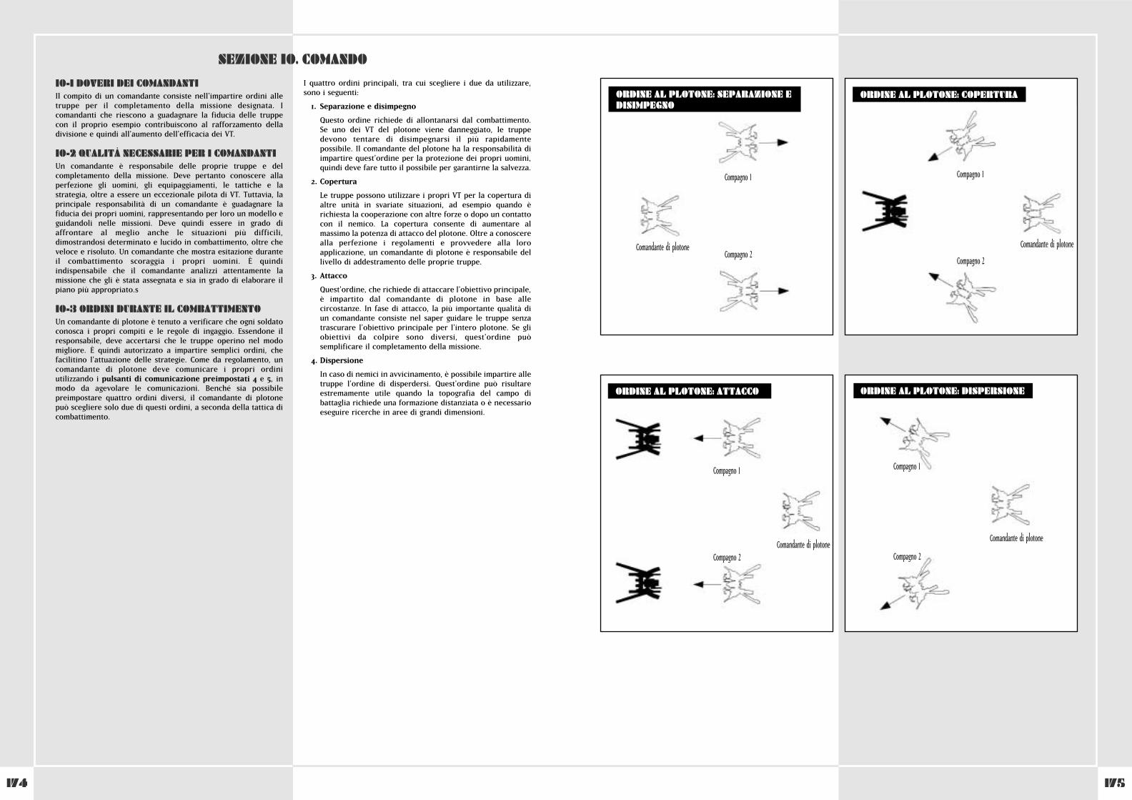
174
10-1 DOVERI DEI COMANDANTIIl compito di un comandante consiste nell'impartire ordini alletruppe per il completamento della missione designata. Icomandanti che riescono a guadagnare la fiducia delle truppecon il proprio esempio contribuiscono al rafforzamento delladivisione e quindi all'aumento dell'efficacia dei VT.
10-2 QUALITÀ NECESSARIE PER I COMANDANTIUn comandante è responsabile delle proprie truppe e delcompletamento della missione. Deve pertanto conoscere allaperfezione gli uomini, gli equipaggiamenti, le tattiche e lastrategia, oltre a essere un eccezionale pilota di VT. Tuttavia, laprincipale responsabilità di un comandante è guadagnare lafiducia dei propri uomini, rappresentando per loro un modello eguidandoli nelle missioni. Deve quindi essere in grado diaffrontare al meglio anche le situazioni più difficili,dimostrandosi determinato e lucido in combattimento, oltre cheveloce e risoluto. Un comandante che mostra esitazione duranteil combattimento scoraggia i propri uomini. È quindiindispensabile che il comandante analizzi attentamente lamissione che gli è stata assegnata e sia in grado di elaborare ilpiano più appropriato.s
10-3 ORDINI DURANTE IL COMBATTIMENTOUn comandante di plotone è tenuto a verificare che ogni soldatoconosca i propri compiti e le regole di ingaggio. Essendone ilresponsabile, deve accertarsi che le truppe operino nel modomigliore. È quindi autorizzato a impartire semplici ordini, chefacilitino l'attuazione delle strategie. Come da regolamento, uncomandante di plotone deve comunicare i propri ordiniutilizzando i pulsanti di comunicazione preimpostati 4 e 5, inmodo da agevolare le comunicazioni. Benché sia possibilepreimpostare quattro ordini diversi, il comandante di plotonepuò scegliere solo due di questi ordini, a seconda della tattica dicombattimento.
I quattro ordini principali, tra cui scegliere i due da utilizzare,sono i seguenti:
1. Separazione e disimpegno
Questo ordine richiede di allontanarsi dal combattimento.Se uno dei VT del plotone viene danneggiato, le truppedevono tentare di disimpegnarsi il più rapidamentepossibile. Il comandante del plotone ha la responsabilità diimpartire quest'ordine per la protezione dei propri uomini,quindi deve fare tutto il possibile per garantirne la salvezza.
2. Copertura
Le truppe possono utilizzare i propri VT per la copertura dialtre unità in svariate situazioni, ad esempio quando èrichiesta la cooperazione con altre forze o dopo un contattocon il nemico. La copertura consente di aumentare almassimo la potenza di attacco del plotone. Oltre a conoscerealla perfezione i regolamenti e provvedere alla loroapplicazione, un comandante di plotone è responsabile dellivello di addestramento delle proprie truppe.
3. Attacco
Quest'ordine, che richiede di attaccare l'obiettivo principale, è impartito dal comandante di plotone in base allecircostanze. In fase di attacco, la più importante qualità diun comandante consiste nel saper guidare le truppe senzatrascurare l'obiettivo principale per l'intero plotone. Se gliobiettivi da colpire sono diversi, quest'ordine puòsemplificare il completamento della missione.
4. Dispersione
In caso di nemici in avvicinamento, è possibile impartire alletruppe l'ordine di disperdersi. Quest'ordine può risultareestremamente utile quando la topografia del campo dibattaglia richiede una formazione distanziata o è necessarioeseguire ricerche in aree di grandi dimensioni.
SEZIONE 10. COMANDO
175
WHEN USING THE PLASMA TORCH
ORDINE AL PLOTONE: SEPARAZIONE EDISIMPEGNO
ORDINE AL PLOTONE: COPERTURA
ORDINE AL PLOTONE: ATTACCO ORDINE AL PLOTONE: DISPERSIONE
Compagno 1
Compagno 2Comandante di plotone
Compagno 1
Compagno 2
Comandante di plotone
Compagno 1
Compagno 2Comandante di plotone
Compagno 1
Compagno 2
Comandante di plotone
174
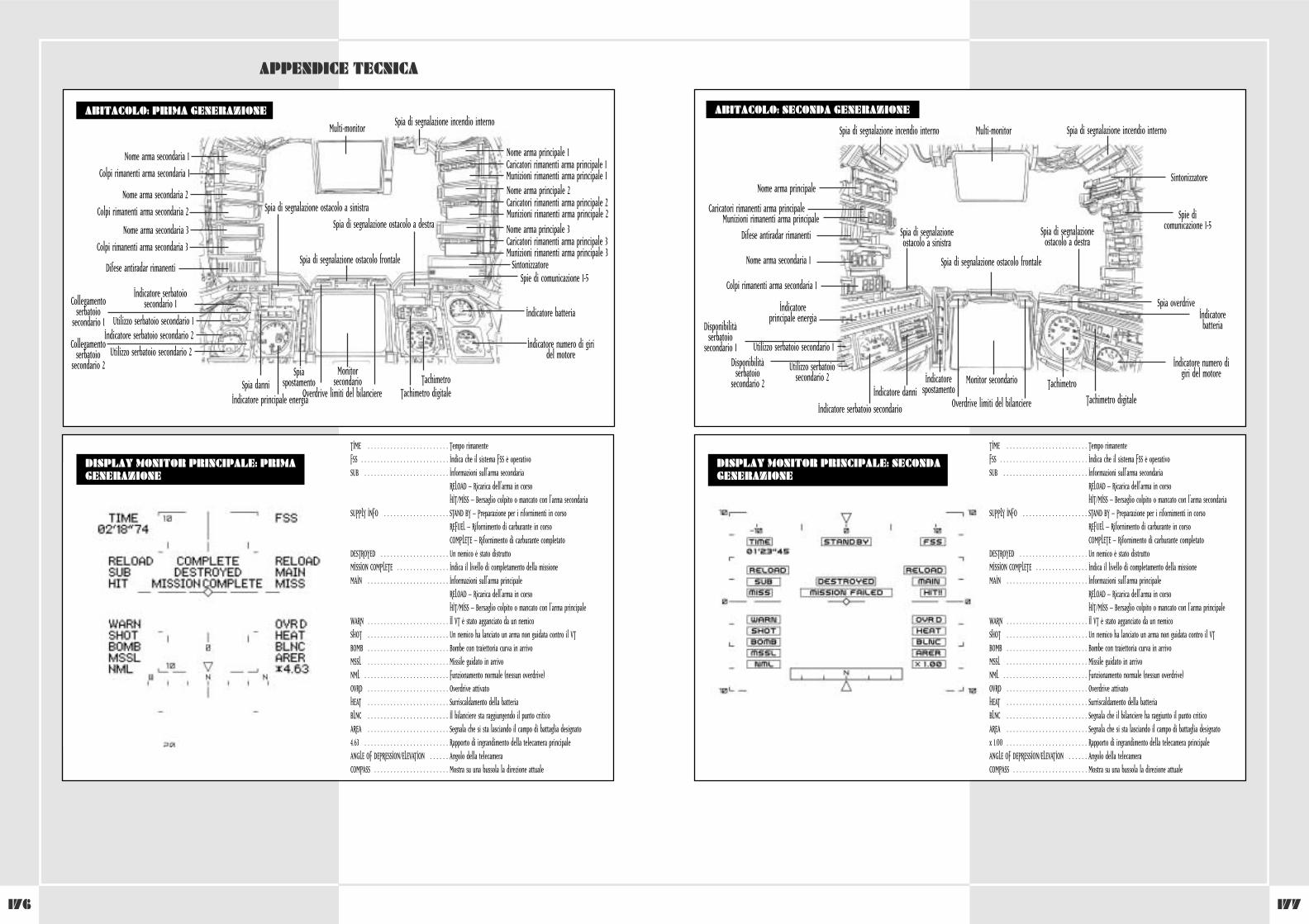
177176
WHEN USING THE PLASMA TORCH
APPENDICE TECNICA
ABITACOLO: PRIMA GENERAZIONE
Spia di segnalazione ostacolo frontale
Multi-monitor
Nome arma secondaria 1
Colpi rimanenti arma secondaria 1
Nome arma principale 1Caricatori rimanenti arma principale 1Munizioni rimanenti arma principale 1
Spia di segnalazione incendio interno
Spia di segnalazione ostacolo a destra
Spia di segnalazione ostacolo a sinistra
Nome arma principale 2Caricatori rimanenti arma principale 2Munizioni rimanenti arma principale 2Nome arma principale 3Caricatori rimanenti arma principale 3Munizioni rimanenti arma principale 3
Spie di comunicazione 1-5
Indicatore batteria
Indicatore numero di giridel motore
Tachimetro
Indicatore principale energiaSpia danni
Monitorsecondario
Spiaspostamento
Tachimetro digitaleOverdrive limiti del bilanciere
Sintonizzatore
Nome arma secondaria 2
Colpi rimanenti arma secondaria 2
Indicatore serbatoiosecondario 1Collegamento
serbatoiosecondario 1 Utilizzo serbatoio secondario 1
Indicatore serbatoio secondario 2Collegamento
serbatoiosecondario 2
Utilizzo serbatoio secondario 2
Nome arma secondaria 3
Colpi rimanenti arma secondaria 3
Difese antiradar rimanenti
WHEN USING THE PLASMA TORCHABITACOLO: SECONDA GENERAZIONE
Spia di segnalazione ostacolo frontale
Overdrive limiti del bilanciere
Multi-monitor
Nome arma principale
Caricatori rimanenti arma principaleMunizioni rimanenti arma principale
Spia di segnalazione incendio interno Spia di segnalazione incendio interno
Spia di segnalazioneostacolo a destra
Spia di segnalazioneostacolo a sinistra
Spie dicomunicazione 1-5
Indicatorebatteria
Spia overdrive
Indicatore numero digiri del motore
Tachimetro
Indicatoreprincipale energia
Indicatore danniMonitor secondarioIndicatore
spostamentoTachimetro digitale
Sintonizzatore
Nome arma secondaria 1
Colpi rimanenti arma secondaria 1
Indicatore serbatoio secondario
Utilizzo serbatoio secondario 1
Disponibilitàserbatoio
secondario 1
Utilizzo serbatoiosecondario 2
Disponibilitàserbatoio
secondario 2
Difese antiradar rimanenti
DISPLAY MONITOR PRINCIPALE: SECONDAGENERAZIONE
TIME . . . . . . . . . . . . . . . . . . . . . . . . . Tempo rimanenteFSS . . . . . . . . . . . . . . . . . . . . . . . . . . . Indica che il sistema FSS è operativoSUB . . . . . . . . . . . . . . . . . . . . . . . . . . Informazioni sull'arma secondaria . . . . . . . . . . . . . . . . . . . . . . . . . . . . . RELOAD – Ricarica dell'arma in corso . . . . . . . . . . . . . . . . . . . . . . . . . . . . . HIT/MISS – Bersaglio colpito o mancato con l'arma secondaria
SUPPLY INFO . . . . . . . . . . . . . . . . . . . . STAND BY – Preparazione per i rifornimenti in corso . . . . . . . . . . . . . . . . . . . . . . . . . . . . . REFUEL – Rifornimento di carburante in corso . . . . . . . . . . . . . . . . . . . . . . . . . . . . . COMPLETE – Rifornimento di carburante completato
DESTROYED . . . . . . . . . . . . . . . . . . . . . Un nemico è stato distruttoMISSION COMPLETE . . . . . . . . . . . . . . . . Indica il livello di completamento della missioneMAIN . . . . . . . . . . . . . . . . . . . . . . . . . Informazioni sull'arma principale . . . . . . . . . . . . . . . . . . . . . . . . . . . . . RELOAD – Ricarica dell'arma in corso . . . . . . . . . . . . . . . . . . . . . . . . . . . . . HIT/MISS – Bersaglio colpito o mancato con l'arma principale
WARN . . . . . . . . . . . . . . . . . . . . . . . . . Il VT è stato agganciato da un nemicoSHOT . . . . . . . . . . . . . . . . . . . . . . . . . Un nemico ha lanciato un arma non guidata contro il VTBOMB . . . . . . . . . . . . . . . . . . . . . . . . . Bombe con traiettoria curva in arrivoMSSL . . . . . . . . . . . . . . . . . . . . . . . . . Missile guidato in arrivoNML . . . . . . . . . . . . . . . . . . . . . . . . . . Funzionamento normale (nessun overdrive)OVRD . . . . . . . . . . . . . . . . . . . . . . . . . Overdrive attivatoHEAT . . . . . . . . . . . . . . . . . . . . . . . . . Surriscaldamento della batteriaBLNC . . . . . . . . . . . . . . . . . . . . . . . . . Segnala che il bilanciere ha raggiunto il punto criticoAREA . . . . . . . . . . . . . . . . . . . . . . . . . Segnala che si sta lasciando il campo di battaglia designatox 1.00 . . . . . . . . . . . . . . . . . . . . . . . . . Rapporto di ingrandimento della telecamera principaleANGLE OF DEPRESSION/ELEVATION . . . . . . Angolo della telecameraCOMPASS . . . . . . . . . . . . . . . . . . . . . . . Mostra su una bussola la direzione attuale
DISPLAY MONITOR PRINCIPALE: PRIMAGENERAZIONE
TIME . . . . . . . . . . . . . . . . . . . . . . . . . Tempo rimanenteFSS . . . . . . . . . . . . . . . . . . . . . . . . . . . Indica che il sistema FSS è operativoSUB . . . . . . . . . . . . . . . . . . . . . . . . . . Informazioni sull'arma secondaria . . . . . . . . . . . . . . . . . . . . . . . . . . . . . RELOAD – Ricarica dell'arma in corso . . . . . . . . . . . . . . . . . . . . . . . . . . . . . HIT/MISS – Bersaglio colpito o mancato con l'arma secondaria
SUPPLY INFO . . . . . . . . . . . . . . . . . . . . STAND BY – Preparazione per i rifornimenti in corso . . . . . . . . . . . . . . . . . . . . . . . . . . . . . REFUEL – Rifornimento di carburante in corso . . . . . . . . . . . . . . . . . . . . . . . . . . . . . COMPLETE – Rifornimento di carburante completato
DESTROYED . . . . . . . . . . . . . . . . . . . . . Un nemico è stato distruttoMISSION COMPLETE . . . . . . . . . . . . . . . . Indica il livello di completamento della missioneMAIN . . . . . . . . . . . . . . . . . . . . . . . . . Informazioni sull'arma principale . . . . . . . . . . . . . . . . . . . . . . . . . . . . . RELOAD – Ricarica dell'arma in corso . . . . . . . . . . . . . . . . . . . . . . . . . . . . . HIT/MISS – Bersaglio colpito o mancato con l'arma principale
WARN . . . . . . . . . . . . . . . . . . . . . . . . . Il VT è stato agganciato da un nemicoSHOT . . . . . . . . . . . . . . . . . . . . . . . . . Un nemico ha lanciato un arma non guidata contro il VTBOMB . . . . . . . . . . . . . . . . . . . . . . . . . Bombe con traiettoria curva in arrivoMSSL . . . . . . . . . . . . . . . . . . . . . . . . . Missile guidato in arrivoNML . . . . . . . . . . . . . . . . . . . . . . . . . . Funzionamento normale (nessun overdrive)OVRD . . . . . . . . . . . . . . . . . . . . . . . . . Overdrive attivatoHEAT . . . . . . . . . . . . . . . . . . . . . . . . . Surriscaldamento della batteriaBLNC . . . . . . . . . . . . . . . . . . . . . . . . . Il bilanciere sta raggiungendo il punto criticoAREA . . . . . . . . . . . . . . . . . . . . . . . . . Segnala che si sta lasciando il campo di battaglia designato4.63 . . . . . . . . . . . . . . . . . . . . . . . . . . Rapporto di ingrandimento della telecamera principaleANGLE OF DEPRESSION/ELEVATION . . . . . . Angolo della telecameraCOMPASS . . . . . . . . . . . . . . . . . . . . . . . Mostra su una bussola la direzione attuale
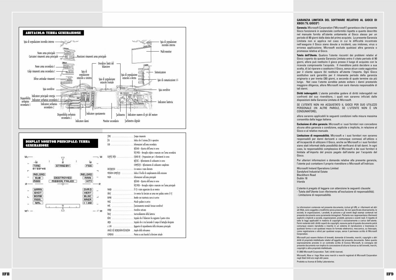
179178
GARANZIA LIMITATA DEL SOFTWARE RELATIVO AL GIOCO DIXBOX ("IL GIOCO")Garanzia. Microsoft Corporation ("Microsoft") garantisce che il presenteGioco funzionerà in sostanziale conformità rispetto a quanto descrittonel manuale fornito all’utente unitamente al Gioco stesso per unperiodo di 90 giorni dalla data del primo acquisto. La presente GaranziaLimitata non si applica nel caso in cui le difficoltà incontratenell'eseguire il Gioco siano dovute a incidenti, uso inidoneo, virus oerronea applicazione. Microsoft esclude qualsiasi altra garanzia opromessa relativa al Gioco.Tutela dell’Utente. Qualora l’utente riscontri dei problemi relativi alGioco coperto da questa Garanzia Limitata entro il citato periodo di 90giorni, allora può restituire il gioco presso il luogo di acquisto con laricevuta comprovante l'acquisto. Il rivenditore potrà decidere a suascelta, di (a) riparare o sostituire il Gioco, senza alcun costo aggiuntivoper il cliente oppure (b) restituire all’utente l'importo. Ogni Giocosostitutivo sarà garantito per il rimanente periodo della garanziaoriginaria o per trenta (30) giorni, a seconda di quale termine sia piùlungo. Nel caso l’utente avrebbe potuto evitare i danni prestandomaggiore diligenza, allora Microsoft non sarà ritenuta responsabile ditali danni.
Diritti inderogabili. L'utente potrebbe godere di diritti inderogabili neiconfronti del suo rivenditore, i quali non saranno inficiati dalledisposizioni della Garanzia Limitata di Microsoft.
SE L’UTENTE NON HA ACQUISTATO IL GIOCO PER SUO UTILIZZOPERSONALE (IN ALTRE PAROLE, SE L'UTENTE NON È UNCONSUMATORE),
allora saranno applicabili le seguenti condizioni nella misura massimaconsentita dalla legge italiana.
Esclusione di altre garanzie. Microsoft e i suoi fornitori non concedonoalcuna altra garanzia o condizione, esplicite o implicite, in relazione alGioco e al relativo manuale.
Limitazione di responsabilità. Microsoft e i suoi fornitori non sarannoresponsabili per danni derivanti o comunque connessi all'utilizzo oall'incapacità di utilizzare il Gioco, anche se Microsoft o i suoi fornitorisiano stati informati della possibilità del verificarsi di tali danni. In ognicaso, la responsabilità complessiva di Microsoft e dei suoi fornitori èlimitata all'importo del prezzo pagato dall’utente per l'acquisto delGioco.
Per ulteriori informazioni o domande relative alla presente garanzia,l’utente può contattare il proprio rivenditore o Microsoft all’indirizzo:
Microsoft Ireland Operations LimitedSandyford Industrial EstateBlackthorn RoadDublin 18Irlanda
L’utente è pregato di leggere con attenzione le seguenti clausole:- Tutela dell’Utente (con riferimento all’esclusione di responsabilità);- Limitazione di responsabilità.
Le informazioni contenute nel presente documento, inclusi gli URL e i riferimenti ad altrisiti Web, sono soggette a modifiche senza preavviso. Se non specificato diversamente, lesocietà, le organizzazioni, i prodotti, le persone e gli eventi degli esempi contenuti nelpresente documento sono puramente immaginari. Pertanto non rappresentano riferimentiespliciti o impliciti a società, organizzazioni, prodotti, persone o eventi reali. Il rispetto ditutte le leggi applicabili in materia di copyright è esclusivamente a carico dell'utente.Fermi restando tutti i diritti coperti da copyright, nessuna parte di questo documento potràcomunque essere riprodotta o inserita in un sistema di riproduzione o trasmessa inqualsiasi forma e con qualsiasi mezzo (in formato elettronico, meccanico, su fotocopia,come registrazione o altro) per qualsiasi scopo, senza il permesso scritto di MicrosoftCorporation. Microsoft può essere titolare di brevetti, domande di brevetto, marchi, copyright o altridiritti di proprietà intellettuale relativi all'oggetto del presente documento. Salvo quantoespressamente previsto in un contratto scritto di licenza Microsoft, la consegna delpresente documento non implica la concessione di alcuna licenza su tali brevetti, marchi,copyright o altra proprietà intellettuale.© 2003 Microsoft Corporation. Tutti i diritti riservati.Microsoft, Xbox e i logo Xbox sono marchi o marchi registrati di Microsoft Corporationnegli Stati Uniti e/o negli altri paesi. Prodotto su licenza di Dolby Laboratories.
WHEN USING THE PLASMA TORCHABITACOLO: TERZA GENERAZIONE
Spia di segnalazioneostacolo frontale
Overdrive limiti delbilanciere
Multi-monitorNome arma principaleCaricatori rimanenti arma principale Munizioni rimanenti arma principale
Spia di segnalazione incendio interno Spia di segnalazioneincendio interno
Spia di segnalazioneostacolo a destra
Spia disegnalazione
ostacolo a sinistraSpie di comunicazione 1-5
Indicatore batteria
Spia overdriveSpia overdrive
Indicatore numero di giri del motoreTachimetro
Indicatore principale energia
Indicatore danni Monitor secondario
Indicatore spostamento
Tachimetro digitale
Sintonizzatore
Nome arma secondaria 1Colpi rimanenti arma secondaria 1
Indicatore serbatoio secondario 1Disponibilitàserbatoio
secondario 1 Indicatore serbatoiosecondario 2
Disponibilità serbatoiosecondario 2
Difese antiradar rimanenti
DISPLAY MONITOR PRINCIPALE: TERZAGENERAZIONE
TIME . . . . . . . . . . . . . . . . . . . . . . Tempo rimanenteFSS . . . . . . . . . . . . . . . . . . . . . . . Indica che il sistema FSS è operativoSUB . . . . . . . . . . . . . . . . . . . . . . . Informazioni sull'arma secondaria
. . . . . . . . . . . . . . . . . . . . . . . . . RELOAD – Ricarica dell'arma in corso . . . . . . . . . . . . . . . . . . . . . . . . . . HIT/MISS – Bersaglio colpito o mancato con l'arma secondariaSUPPLY INFO . . . . . . . . . . . . . . . . . STAND BY – Preparazione per i rifornimenti in corso . . . . . . . . . . . . . . . . . . . . . . . . . . REFUEL – Rifornimento di carburante in corso . . . . . . . . . . . . . . . . . . . . . . . . . . COMPLETE – Rifornimento di carburante completatoDESTROYED . . . . . . . . . . . . . . . . . Un nemico è stato distruttoMISSION COMPLETE . . . . . . . . . . . . Indica il livello di completamento della missioneMAIN . . . . . . . . . . . . . . . . . . . . . . Informazioni sull'arma principale . . . . . . . . . . . . . . . . . . . . . . . . . . RELOAD – Ricarica dell'arma in corso . . . . . . . . . . . . . . . . . . . . . . . . . . HIT/MISS – Bersaglio colpito o mancato con l'arma principaleWARN . . . . . . . . . . . . . . . . . . . . . Il VT è stato agganciato da un nemicoSHOT . . . . . . . . . . . . . . . . . . . . . . Un nemico ha lanciato un arma non guidata contro il VTBOMB . . . . . . . . . . . . . . . . . . . . . Bombe con traiettoria curva in arrivoMSSL . . . . . . . . . . . . . . . . . . . . . . Missile guidato in arrivoNML . . . . . . . . . . . . . . . . . . . . . . Funzionamento normale (nessun overdrive)OVRD . . . . . . . . . . . . . . . . . . . . . Overdrive attivatoHEAT . . . . . . . . . . . . . . . . . . . . . . Surriscaldamento della batteriaBLNC . . . . . . . . . . . . . . . . . . . . . . Segnala che il bilanciere ha raggiunto il punto criticoAREA . . . . . . . . . . . . . . . . . . . . . . Segnala che si sta lasciando il campo di battaglia designatox 1.00 . . . . . . . . . . . . . . . . . . . . . Rapporto di ingrandimento della telecamera principaleANGLE OF DEPRESSION/ELEVATION . . Angolo della telecameraCOMPASS . . . . . . . . . . . . . . . . . . . Mostra su una bussola la direzione attuale
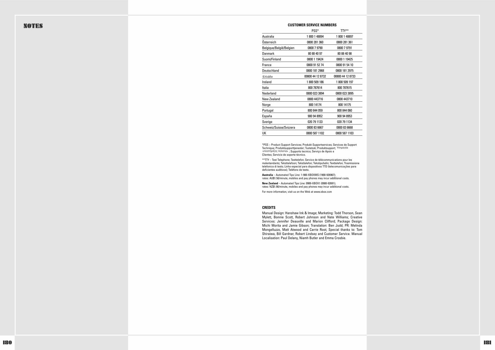
181180
CUSTOMER SERVICE NUMBERSPSS* TTY**
Australia 1 800 1 48894 1 800 1 48897
Österreich 0800 281 360 0800 281 361
Belgique/België/Belgien 0800 7 9790 0800 7 9791
Danmark 80 88 40 97 80 88 40 98
Suomi/Finland 0800 1 19424 0800 1 19425
France 0800 91 52 74 0800 91 54 10
Deutschland 0800 181 2968 0800 181 2975
00800 44 12 8732 00800 44 12 8733
Ireland 1 800 509 186 1 800 509 197
Italia 800 787614 800 787615
Nederland 0800 023 3894 0800 023 3895
New Zealand 0800 443716 0800 443710
Norge 800 14174 800 14175
Portugal 800 844 059 800 844 060
España 900 94 8952 900 94 8953
Sverige 020 79 1133 020 79 1134
Schweiz/Suisse/Svizzera 0800 83 6667 0800 83 6668
UK 0800 587 1102 0800 587 1103
*PSS – Product Support Services; Produkt-Supportservices; Services de SupportTechnique; Produktsupporttjenester; Tuotetuki; Produktsupport;
; Supporto tecnico; Serviço de Apoio aClientes; Servicio de soporte técnico.
**TTY – Text Telephone; Texttelefon; Service de télécommunications pour lesmalentendants; Teksttelefoon; Teksttelefon; Tekstipuhelin; Texttelefon; Trasmissionetelefonica di testo; Linha especial para dispositivos TTD (telecomunicações paradeficientes auditivos); Teléfono de texto.
Australia – Automated Tips Line: 1-900-XBOXMS (1900-926967); rates: AU$1.50/minute, mobiles and pay phones may incur additional costs.
New Zealand – Automated Tips Line: 0900-XBOX1 (0900-92691); rates: NZ$1.90/minute, mobiles and pay phones may incur additional costs.
For more information, visit us on the Web at www.xbox.com
CREDITSManual Design: Hanshaw Ink & Image; Marketing: Todd Thorson, SeanMylett, Bonnie Scott, Robert Johnson and Nate Williams; CreativeServices: Jennifer Deauville and Marion Clifford; Package Design:Michi Morita and Jamie Gibson; Translation: Ben Judd; PR: MelindaMongelluzzo, Matt Atwood and Carrie Root; Special thanks to: TomShiraiwa, Bill Gardner, Robert Lindsey and Customer Service. ManualLocalisation: Paul Delany, Niamh Butler and Emma Crosbie.
Eλλáδa
NOTES


