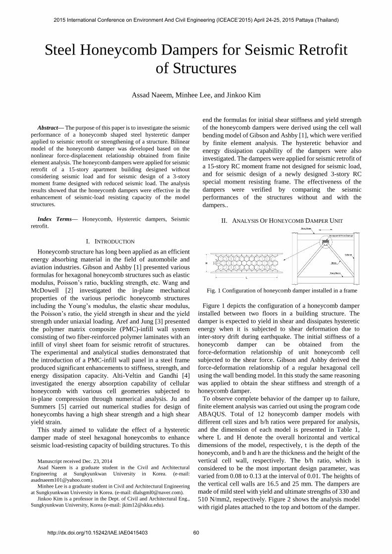
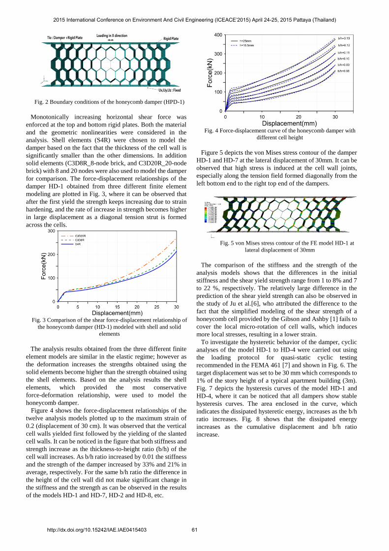
Abstract— The purpose of this paper is to investigate the seismic
performance of a honeycomb shaped steel hysteretic damper
applied to seismic retrofit or strengthening of a structure. Bilinear
model of the honeycomb damper was developed based on the
nonlinear force-displacement relationship obtained from finite
element analysis. The honeycomb dampers were applied for seismic
retrofit of a 15-story apartment building designed without
considering seismic load and for seismic design of a 3-story
moment frame designed with reduced seismic load. The analysis
results showed that the honeycomb dampers were effective in the
enhancement of seismic-load resisting capacity of the model
structures.
Index Terms— Honeycomb, Hysteretic dampers, Seismic
retrofit.
I. INTRODUCTION
Honeycomb structure has long been applied as an efficient
energy absorbing material in the field of automobile and
aviation industries. Gibson and Ashby [1] presented various
formulas for hexagonal honeycomb structures such as elastic
modulus, Poisson’s ratio, buckling strength, etc. Wang and
McDowell [2] investigated the in-plane mechanical
properties of the various periodic honeycomb structures
including the Young’s modulus, the elastic shear modulus,
the Poisson’s ratio, the yield strength in shear and the yield
strength under uniaxial loading. Aref and Jung [3] presented
the polymer matrix composite (PMC)-infill wall system
consisting of two fiber-reinforced polymer laminates with an
infill of vinyl sheet foam for seismic retrofit of structures.
The experimental and analytical studies demonstrated that
the introduction of a PMC-infill wall panel in a steel frame
produced significant enhancements to stiffness, strength, and
energy dissipation capacity. Alti-Veltin and Gandhi [4]
investigated the energy absorption capability of cellular
honeycomb with various cell geometries subjected to
in-plane compression through numerical analysis. Ju and
Summers [5] carried out numerical studies for design of
honeycombs having a high shear strength and a high shear
yield strain.
This study aimed to validate the effect of a hysteretic
damper made of steel hexagonal honeycombs to enhance
seismic load-resisting capacity of building structures. To this
Manuscript received Dec. 23, 2014
Asad Naeem is a graduate student in the Civil and Architectural
Engineering at Sungkyunkwan University in Korea. (e-mail:
Minhee Lee is a graduate student in Civil and Architectural Engineering
at Sungkyunkwan University in Korea. (e-mail: [email protected]).
Jinkoo Kim is a professor in the Dept. of Civil and Architectural Eng.,
Sungkyunkwan University, Korea (e-mail: [email protected]).
end the formulas for initial shear stiffness and yield strength
of the honeycomb dampers were derived using the cell wall
bending model of Gibson and Ashby [1], which were verified
by finite element analysis. The hysteretic behavior and
energy dissipation capability of the dampers were also
investigated. The dampers were applied for seismic retrofit of
a 15-story RC moment frame not designed for seismic load,
and for seismic design of a newly designed 3-story RC
special moment resisting frame. The effectiveness of the
dampers were verified by comparing the seismic
performances of the structures without and with the
dampers..
II. ANALYSIS OF HONEYCOMB DAMPER UNIT
Fig. 1 Configuration of honeycomb damper installed in a frame
Figure 1 depicts the configuration of a honeycomb damper
installed between two floors in a building structure. The
damper is expected to yield in shear and dissipates hysteretic
energy when it is subjected to shear deformation due to
inter-story drift during earthquake. The initial stiffness of a
honeycomb damper can be obtained from the
force-deformation relationship of unit honeycomb cell
subjected to the shear force. Gibson and Ashby derived the
force-deformation relationship of a regular hexagonal cell
using the wall bending model. In this study the same reasoning
was applied to obtain the shear stiffness and strength of a
honeycomb damper.
To observe complete behavior of the damper up to failure,
finite element analysis was carried out using the program code
ABAQUS. Total of 12 honeycomb damper models with
different cell sizes and b/h ratios were prepared for analysis,
and the dimension of each model is presented in Table 1,
where L and H denote the overall horizontal and vertical
dimensions of the model, respectively, t is the depth of the
honeycomb, and b and h are the thickness and the height of the
vertical cell wall, respectively. The b/h ratio, which is
considered to be the most important design parameter, was
varied from 0.08 to 0.13 at the interval of 0.01. The heights of
the vertical cell walls are 16.5 and 25 mm. The dampers are
made of mild steel with yield and ultimate strengths of 330 and
510 N/mm2, respectively. Figure 2 shows the analysis model
with rigid plates attached to the top and bottom of the damper.
Steel Honeycomb Dampers for Seismic Retrofit
of Structures
Assad Naeem, Minhee Lee, and Jinkoo Kim
2015 International Conference on Environment And Civil Engineering (ICEACE’2015) April 24-25, 2015 Pattaya (Thailand)
http://dx.doi.org/10.15242/IAE.IAE0415403 60
Fig. 2 Boundary conditions of the honeycomb damper (HPD-1)
Monotonically increasing horizontal shear force was
enforced at the top and bottom rigid plates. Both the material
and the geometric nonlinearities were considered in the
analysis. Shell elements (S4R) were chosen to model the
damper based on the fact that the thickness of the cell wall is
significantly smaller than the other dimensions. In addition
solid elements (C3D8R_8-node brick, and C3D20R_20-node
brick) with 8 and 20 nodes were also used to model the damper
for comparison. The force-displacement relationships of the
damper HD-1 obtained from three different finite element
modeling are plotted in Fig. 3, where it can be observed that
after the first yield the strength keeps increasing due to strain
hardening, and the rate of increase in strength becomes higher
in large displacement as a diagonal tension strut is formed
across the cells.
Fig. 3 Comparison of the shear force-displacement relationship of
the honeycomb damper (HD-1) modeled with shell and solid
elements
The analysis results obtained from the three different finite
element models are similar in the elastic regime; however as
the deformation increases the strengths obtained using the
solid elements become higher than the strength obtained using
the shell elements. Based on the analysis results the shell
elements, which provided the most conservative
force-deformation relationship, were used to model the
honeycomb damper.
Figure 4 shows the force-displacement relationships of the
twelve analysis models plotted up to the maximum strain of
0.2 (displacement of 30 cm). It was observed that the vertical
cell walls yielded first followed by the yielding of the slanted
cell walls. It can be noticed in the figure that both stiffness and
strength increase as the thickness-to-height ratio (b/h) of the
cell wall increases. As b/h ratio increased by 0.01 the stiffness
and the strength of the damper increased by 33% and 21% in
average, respectively. For the same b/h ratio the difference in
the height of the cell wall did not make significant change in
the stiffness and the strength as can be observed in the results
of the models HD-1 and HD-7, HD-2 and HD-8, etc.
Fig. 4 Force-displacement curve of the honeycomb damper with
different cell height
Figure 5 depicts the von Mises stress contour of the damper
HD-1 and HD-7 at the lateral displacement of 30mm. It can be
observed that high stress is induced at the cell wall joints,
especially along the tension field formed diagonally from the
left bottom end to the right top end of the dampers.
Fig. 5 von Mises stress contour of the FE model HD-1 at
lateral displacement of 30mm
The comparison of the stiffness and the strength of the
analysis models shows that the differences in the initial
stiffness and the shear yield strength range from 1 to 8% and 7
to 22 %, respectively. The relatively large difference in the
prediction of the shear yield strength can also be observed in
the study of Ju et al.[6], who attributed the difference to the
fact that the simplified modeling of the shear strength of a
honeycomb cell provided by the Gibson and Ashby [1] fails to
cover the local micro-rotation of cell walls, which induces
more local stresses, resulting in a lower strain.
To investigate the hysteretic behavior of the damper, cyclic
analyses of the model HD-1 to HD-4 were carried out using
the loading protocol for quasi-static cyclic testing
recommended in the FEMA 461 [7] and shown in Fig. 6. The
target displacement was set to be 30 mm which corresponds to
1% of the story height of a typical apartment building (3m).
Fig. 7 depicts the hysteresis curves of the model HD-1 and
HD-4, where it can be noticed that all dampers show stable
hysteresis curves. The area enclosed in the curve, which
indicates the dissipated hysteretic energy, increases as the b/h
ratio increases. Fig. 8 shows that the dissipated energy
increases as the cumulative displacement and b/h ratio
increase.
2015 International Conference on Environment And Civil Engineering (ICEACE’2015) April 24-25, 2015 Pattaya (Thailand)
http://dx.doi.org/10.15242/IAE.IAE0415403 61
Fig. 6 Displacement loading history specified in FEMA 461
Fig. 7 Hysteresis diagram of the honeycomb dampers HD-1
(b/h=0.08)
Fig. 8 Cumulative dissipated energy of the honeycomb dampers
III. SEISMIC PERFORMANCE OF THE MODEL STRUCTURE
INSTALLED WITH HONEYCOMB DAMPERS
For seismic retrofit of the analysis model structure, two
honeycomb dampers were installed per story in the center
frame of the model structure along the longitudinal direction
as depicted in Fig. 9. Dampers were installed between two
floors using the rigid chevron bracing from 2nd to 9th story
where inter-story drifts are relatively large. Based on some
trials, it was confirmed that the strength of the retrofitted
structure satisfied the design base shear when the shear
capacity of the dampers installed in each story was 27.5% of
the design base shear, which is 475 kN. The dimension of the
damper was determined so that the maximum shear strain of
0.2 was reached at the inter-story drift of 1.5 % of the story
height. The total width and height of the damper were
determined to be 1,067mm and 198 mm, respectively, and
the height and the thickness of each cell wall are 22mm and
2.9 mm, respectively. The depth of the damper was
determined as 100mm. Using Eq. (11) to (15) the initial and
the post-yield stiffness are computed as 159.19 and 17.51
kN/mm, respectively, and the yield and ultimate strength are
237.37 and 751.10 kN, respectively.
Fig. 9 Location of honeycomb dampers in the 15-story structure
The bi-linear behavior of the honeycomb damper was
modeled using the ‘Rubber Type Seismic Isolator Element’
in the Perform 3D. Fig. 10 shows the pushover curves of the
structure along the longitudinal direction before and after the
retrofit. It can be observed that both stiffness and strength of
the model structure increased significantly as a result of the
damper installation. It was observed that plastic hinges first
formed at the middle story beams and spread to the beams in
the nearby stories, as observed in the structure before retrofit.
Nonlinear dynamic analyses were carried out using the
seven earthquake records provided in the Pacific Earthquake
Engineering Research (PEER) Center NGA Database. The
characteristics of the records are presented in Table 5. Fig. 11
shows the time histories of the top story displacements of the
structure before and after the retrofit obtained from the
analysis. It can be observed that in most cases both the
maximum displacement and the permanent displacement
decreased due to the installation of the dampers. Fig. 12
depicts the hysteresis curve of the damper located in the
second story during Kobe earthquake, where it can be
observed that the dampers experienced many cycles of full
yielding, dissipating large amount of seismic energy...
2015 International Conference on Environment And Civil Engineering (ICEACE’2015) April 24-25, 2015 Pattaya (Thailand)
http://dx.doi.org/10.15242/IAE.IAE0415403 62
Fig. 10 Pushover curves of the model structure before and after
retrofit with honeycomb dampers
(a)
Fig. 11 Nonlinear dynamic analysis results of the model structure
for Loma Prieta earthquake records
Fig. 12 Hysteresis loop of the 2nd story honeycomb damper
subjected to Kobe EQ
IV. CONCLUSION
The honeycomb dampers were applied for seismic retrofit
of a 15-story RC moment frame building and for alternative
seismic design of a 3-story moment frame. The analysis
results of the model structures using seven earthquake
records showed that the honeycomb dampers contributed
significantly to the enhancement of the strength and stiffness
of the model structure. The nonlinear time history analysis
results showed that after installation of the dampers the
permanent displacements were significantly reduced. It was
also observed that in the structure with honeycomb dampers
large amount of energy was dissipated in the dampers
resulting in less damage in the structural members..
ACKNOWLEDGMENT
This research was supported by a grant
(13AUDP-B066083-01) from Architecture & Urban
Development Research Program funded by Ministry of Land,
Infrastructure and Transport of Korean government.
REFERENCES
[1] Gibson L.J., Ashby M.F.(1997) Cellular solids Structure and
Properties, 2nd ed., Cambridge University Press, Cambridge, UK...
http://dx.doi.org/10.1017/CBO9781139878326
[2] Wang A.-J., McDowell D.L.(2004) In-Plane Stiffness and Yield
Strength of Periodic Metal Honeycombs, Journal of Engineering
Materials and Technology, 126, 137-156.
http://dx.doi.org/10.1115/1.1646165
[3] Aref A.J., Jung W.(2003) Energy-Dissipating Polymer Matrix
Composite-Infill Wall System for Seismic Retrofitting, Journal of
Structural Engineering, 129, 440-448.
http://dx.doi.org/10.1061/(ASCE)0733-9445(2003)129:4(440)
[4] Alti-Veltin B., Gandhi F. (2010) Effect of Cell Geometry on Energy
Absorption of Honeycomb Under In-Plane Compression, American
Institute of Aeronautics and Astronautics, 466-478.
[5] Ju J.,Summers J.D.(2011) Compliant Hexagonal Periodic Lattice
Structures Having Both High Shear Strength and High Shear Strain,
Material and Design, 32(2), 512-524.
http://dx.doi.org/10.1016/j.matdes.2010.08.029
[6] Ju J., Summers J.D., Ziegert J., George Fadel (2012) Design of
Honeycombs for Modulus and Yield Strain in Shear, Journal of
Engineering Materials and Technology, 134(1), 011002
http://dx.doi.org/10.1115/1.4004488
[7] Federal Emergency Management Agency (FEMA) (2007) Interim
protocols for determining seismic performance characteristics of
structural and nonstructural components. Report No. FEMA 461,
Washington, DC, USA
Asad Naeem is a graduate student in the Civil and
Architectural Engineering at Sungkyunkwan
University in Korea. He received his BS from Dept.
of Civill Eng., Hanra University in Pakistan in
2013.
Minhee Lee is a graduate student in Civil and
Architectural Engineering at Sungkyunkwan
University in Korea. She received BS from Dept.
of Architectural Eng., Kookmin University in
Korea in 2011
Jinkoo Kim is Professor of Civil and
Architectural Engineering at Sungkyunkwan
University in Korea. He received MS and PhD
from Dept. of Civil and Environmental
Engineering, Massachusetts Institute of
Technology in US.
2015 International Conference on Environment And Civil Engineering (ICEACE’2015) April 24-25, 2015 Pattaya (Thailand)
http://dx.doi.org/10.15242/IAE.IAE0415403 63