STEEL PLATE SHEAR WALLS (SPSW), TEBF, CFST, SF, AND OTHER SHORT STORIES MICHEL BRUNEAU, Ph.D., P.Eng, F.ASCE Department of Civil, Structural, and Environmental Engineering University at Buffalo 716-645-3398 [email protected]www.michelbruneau.com Michel Bruneau has conducted research on the evaluation and retrofit of existing steel bridges and buildings subjected to destructive forces, as well as on the development of new design concepts capable of providing satisfactory seismic-resistance, blast-resistance, or both (as multi-hazard resistant concepts). He has conducted reconnaissance visits to numerous disaster stricken areas, is a member of various AISC and CSA specifications-writing committees, and served as Director of the Multidisciplinary Center for Earthquake Engineering Research. Dr. Bruneau has authored over 400 technical publications, including the textbook “Ductile Design of Steel Structures,” and two fiction books. He has received many awards for his technical work (as well as for his latest novel). Abstract This paper presents brief information summaries on Steel Plate Shear Walls (SPSWs), Perforated SPSWs (P-SPSWs), Tubular Eccentrically Braced Frames (TEBFs), Concrete Filled Steel Tubes (CFSTs), Structural Fuses (SFs), Rocking Frames (RFs), and Self-Centering SPSWs (SC- SPSWs). This paper focuses on the research results of former graduate students with whom the author had the pleasure to work 1 . References are provided for the readers who wish to study specific topics in more depth. A broader list of emerging structural systems is available in Bruneau et al. (2011). Additional technical information can also be found at www.michelbruneau.com. Note For brevity, hundreds of references to the work of other researchers who contributed to each of the topic covered here have been omitted in this paper. Without fault, the reader will find those comprehensive citation lists in the literature reviews of the relevant papers cited here. 1 More specifically for the information presented in this paper, Samer El-Bahey (Stevenson & Associates), Jeffrey Berman (University of Washington, Seattle), Daniel Dowden (Ph.D. Candidate, University at Buffalo), Shuichi Fujikura (ARUP), Michael Pollino (Case Western Reserve University), Ronny Purba (Ph.D. Candidate, University at Buffalo), Bing Qu (California Polytechnic State University), Ramiro Vargas (Technological University of Panama), Darren Vian (Parsons Brinkerhoff). Not all concepts and systems compatible with the objective of this paper could be presented here, but the relevant work of other former graduate students can be found on the aforementioned webpage.
Transcript
STEEL PLATE SHEAR WALLS (SPSW), TEBF, CFST, SF, AND OTHER SHORT STORIES
MICHEL BRUNEAU, Ph.D., P.Eng, F.ASCE Department of Civil, Structural, and Environmental Engineering University at Buffalo 716-645-3398 [email protected] www.michelbruneau.com Michel Bruneau has conducted research on the evaluation and retrofit of existing steel bridges and buildings subjected to destructive forces, as well as on the development of new design concepts capable of providing satisfactory seismic-resistance, blast-resistance, or both (as multi-hazard resistant concepts). He has conducted reconnaissance visits to numerous disaster stricken areas, is a member of various AISC and CSA specifications-writing committees, and served as Director of the Multidisciplinary Center for Earthquake Engineering Research.
Dr. Bruneau has authored over 400 technical publications, including the textbook “Ductile Design of Steel Structures,” and two fiction books. He has received many awards for his technical work (as well as for his latest novel). Abstract This paper presents brief information summaries on Steel Plate Shear Walls (SPSWs), Perforated SPSWs (P-SPSWs), Tubular Eccentrically Braced Frames (TEBFs), Concrete Filled Steel Tubes (CFSTs), Structural Fuses (SFs), Rocking Frames (RFs), and Self-Centering SPSWs (SC-SPSWs). This paper focuses on the research results of former graduate students with whom the author had the pleasure to work1. References are provided for the readers who wish to study specific topics in more depth. A broader list of emerging structural systems is available in Bruneau et al. (2011). Additional technical information can also be found at www.michelbruneau.com. Note For brevity, hundreds of references to the work of other researchers who contributed to each of the topic covered here have been omitted in this paper. Without fault, the reader will find those comprehensive citation lists in the literature reviews of the relevant papers cited here.
1 More specifically for the information presented in this paper, Samer El-Bahey (Stevenson & Associates), Jeffrey Berman (University of Washington, Seattle), Daniel Dowden (Ph.D. Candidate, University at Buffalo), Shuichi Fujikura (ARUP), Michael Pollino (Case Western Reserve University), Ronny Purba (Ph.D. Candidate, University at Buffalo), Bing Qu (California Polytechnic State University), Ramiro Vargas (Technological University of Panama), Darren Vian (Parsons Brinkerhoff). Not all concepts and systems compatible with the objective of this paper could be presented here, but the relevant work of other former graduate students can be found on the aforementioned webpage.
Introduction New structural systems and concepts can add to the Structural Engineer’s “toolbox,” providing him/her with an ever increasing range of solutions to meet increasingly complex design challenges. In keeping with this analogy, the objective of this paper is to provide an overview of some recently developed “tools” that can enrich this toolbox. This objective leads to a presentation that is somewhat unconventional, resulting in a paper that has more breadth than depth and consisting mainly of brief topic summaries redirected to references to be consulted to further explore specific ideas. To limit the scope of this paper, the information presented here only refers to the research results of former graduate students with whom the author had the pleasure to work (see list previous page). As such, focus here is on Steel Plate Shear Walls (SPSWs), Perforated SPSWs (P-SPSWs), Tubular Eccentrically Braced Frames (TEBFs), Concrete Filled Steel Tubes (CFSTs), Structural Fuses (SFs), Rocking Frames (RFs), and Self-Centering SPSWs (SC-SPSWs). A broader list of emerging structural systems, and more comprehensive lists of relevant references, are available elsewhere (Bruneau et al. 2011). Steel Plate Shear Walls (SPSWs) Steel plate shear walls (SPSWs) have been constructed before codified requirements for their design existed. Designed and detailed based on engineering principles, their characteristics have evolved over time, reflecting improvements in knowledge on this topic as instructed by research. A comprehensive survey of buildings having SPSWs for their lateral load resisting structural system, and of determinant research on that topic at the time, has been presented by Sabelli and Bruneau (2007). The number of buildings having SPSWs and of research projects studying that structural system has increased substantially since it has been introduced in design specifications (CSA 1994, 2001, 2009; AISC 2005, 2010). For multistory SPSWs, plastic analysis can be used to predict ultimate capacity. The desirable plastic mechanism involves uniform yielding of the plates over every story (Figure 1b). The corresponding ultimate strength of SPSW having rigid beam-to-column connections capable of developing the beam’s plastic moment, calculated by the kinematic approach, is:
( ) ∑∑∑ +−= +
sss n
ipbi
n
iiiiy
n
iii MLhttFhV 22sin
21
1 α (1)
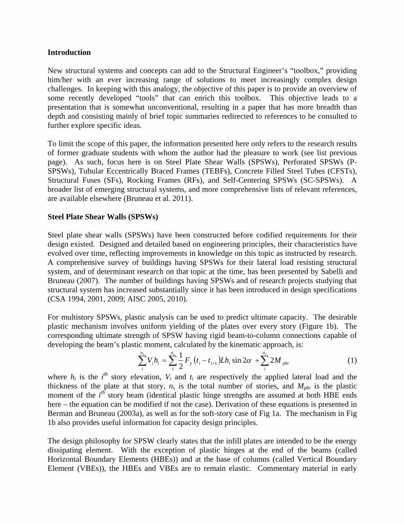
where hi is the ith story elevation, Vi and ti are respectively the applied lateral load and the thickness of the plate at that story, ns is the total number of stories, and Mpbi is the plastic moment of the ith story beam (identical plastic hinge strengths are assumed at both HBE ends here – the equation can be modified if not the case). Derivation of these equations is presented in Berman and Bruneau (2003a), as well as for the soft-story case of Fig 1a. The mechanism in Fig 1b also provides useful information for capacity design principles.
The design philosophy for SPSW clearly states that the infill plates are intended to be the energy dissipating element. With the exception of plastic hinges at the end of the beams (called Horizontal Boundary Elements (HBEs)) and at the base of columns (called Vertical Boundary Element (VBEs)), the HBEs and VBEs are to remain elastic. Commentary material in early
specifications provided alternative methods to calculate forces in VBE, but some of these methods were demonstrated to lead to incorrect results and subsequently deleted in AISC 341-10. The systematic free-body-diagram approach proposed by Berman and Bruneau (2008a) has been shown to better match results from push-over analysis.
(a) (b) Figure 1. SPSW Plastic Mechanisms (Berman and Bruneau 2003b, Courtesy of MCEER, University at Buffalo): (a)
Soft-Story Mechanism; (b) Uniform Yielding Mechanism VBE design is also currently subjected to flexibility limits. After SPSW specimens by Lubell, et al. (2000) exhibited significant "pull-in" deformation or undesirable premature out-of-plane buckling, Montgomery and Medhekar (2001) ascribed this poor performance to insufficient VBE stiffness, on the rationale that if VBEs deform excessively, they may be unable to anchor the infill panel yield forces. For that reason (as well as to ensure uniform yielding of the infill plate), CSA S16-01 introduced the flexibility factor, ωt , proposed in previous analytical work of plate girder theory (Wagner 1931, Kuhn et al. 1952 – summarized in Qu and Bruneau 2008, 2010b), as an index of VBE flexibility, defined as:
40.72
wit si
c
th
I Lω = (2)
where twi is the web plate thickness, L and hsi are the width and height of the SPSW panel, and Ic is the inertia of a VBE adjacent to the panel. Noting that the Lubell et al. specimens had flexibility factors of 3.35, and that all other known tested SPSWs that behaved in a ductile manner had flexibility factors of 2.5 or less, CSA S16-01 empirically specified an upper bound
of 2.5 on tω . With that upper bound of 2.5 on Equation 2 and solving for cI leads to the following requirement, first implemented in CSA S16-01, and subsequently AISC 341:
40.00307 wi si
ct h
IL
≥ (3)
However, Qu and Bruneau (2008, 2010b) found that, for seismic design, this existing limit is uncorrelated to satisfactory in-plane and out-of-plane VBE performance, and that the significant inward inelastic deformations of VBEs observed in past tests were not directly caused by excessive VBE flexibilities but rather due to shear yielding at the ends of VBEs. Significantly, the data presented by Qu and Bruneau included a test by Lee and Tsai (2008) having ωt =3.0, with adequate VBE shear strength and exhibiting satisfactory behavior.
As a result, both AISC 341-10 and CSA-S16-09 indicate that shear yielding may be a governing limit state in VBEs. Accounting for shear, axial, and flexure interaction is recommended for VBE design to ensure elastic response. In future editions of the seismic provisions, the flexibility limit may either disappear or be kept for other reasons.
As far as HBE design is concerned, HBE stiffness impacts the progression of yielding in web plates. Using a strip model, Bruneau and Bhagwagar (2002) showed that, at the extreme, for infinitely elastic HBEs and VBEs of low stiffness in SPSWs having large panel aspect ratios, L/h, some strips may even end-up in compression because of HBE deflections induced by other strips in tension. However, such an extreme response is unlikely in actual designs, given that HBE stiffness is related to strength. Rather, progressive yielding across the width of a given web plate is typically observed upon increasing SPSW drift, as shown in Figure 2c for the first story web plates of specimens tested by Driver (1997) and Lee and Tsai (2008) and having substantially different boundary frame flexibility. This progression of yielding is also exhibited in the push-over curves, such as those shown in Figure 2a. HBE stiffness should be adequate to achieve development of the web plates’ full yield strength at the design drift. Note that infinitely rigid pin-ended HBEs and VBEs would be required to achieve simultaneous yielding of all strips across a web plate.
Strengthwise, HBEs are simultaneously subjected to flexural moments, shear and axial forces. In addition, when shear stresses and axial stresses perpendicular to the HBE’s longitudinal axis are significant in the webs of HBEs, this should also be taken into account in the interaction equations. A procedure to account for these effects in calculating plastic hinge strength has been proposed by Qu and Bruneau (2010a, 2011).
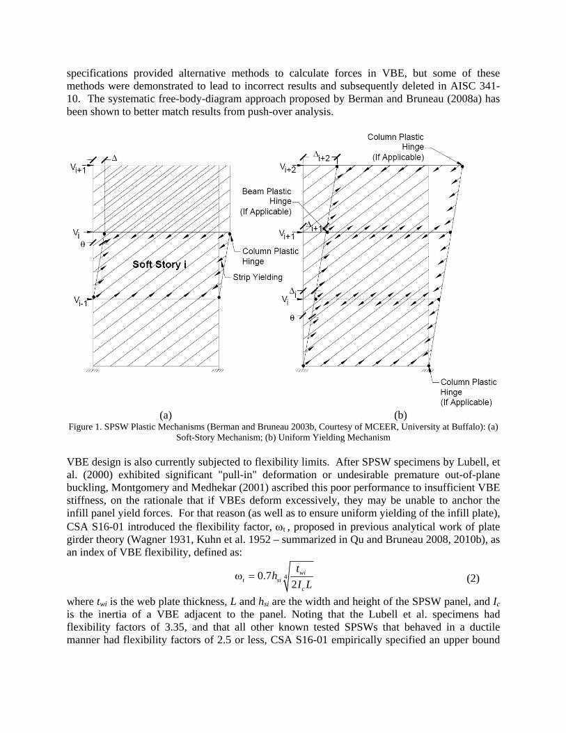
HBEs should also be designed such that their plastic strength is not reached at any point along their length, except at their ends. Vian and Bruneau (2005), using the equilibrium method, demonstrated that HBEs must be designed to resist ωL2/4 to prevent in-span hinges, as illustrated in Figure 3. Purba and Bruneau (2010, 2012) demonstrated that plastification along HBE spans can induce significant (and possibly excessive) accumulation of plastic incremental deformations on the HBEs, themselves leading to only partial yielding of the infill plates and correspondingly lower global plastic strength compared to the values predicted by code equations. Sample nonlinear time history analysis results for SPSWs having HBEs designed to prevent in-span hinging (SPSW-CD case) or not (SPSW-ID case) are compared in Figure 4.
Specimen: Two-story SPSW (SPSW S)Flexibility factor: ωt=3.01Researchers: Tsai and Lee (2007)
( a )
0.0 0.1 0.2 0.3 0.4 0.5 0.6 0.7 0.8 0.9 1.0x/lα
0.00.20.40.60.81.01.2
σ / f
y
1F Drift = 2.0%
Lee and Tsai (2008)Driver (1997)
0.00.20.40.60.81.01.2
σ / f
y
1F Drift = 0.6%
0.00.20.40.60.81.01.2
σ / f
y
1F Drift = 0.3%
0.00.20.40.60.81.01.2
σ / f
y
1F Drift = 0.2%
0.00.20.40.60.81.01.2
σ / f
y
1F Drift = 0.1%
( c )
o
x
lα
( b )
Figure 2 Uniformity of Tension Fields (a) Pushover Curves, (b) Schematic of Tension Fields, (c) Uniformity of Panel Stresses (Qu and Bruneau 2008, Courtesy of MCEER, University at Buffalo)
-2.0
-1.5
-1.0
-0.5
0.0
0.5
1.0
1.5
2.0
0 0.1 0.2 0.3 0.4 0.5 0.6 0.7 0.8 0.9 1Fraction of span from left support
Nor
mal
ized
Mom
ent:
M(x
) / ( ω
L2 /8)
κ=0.0κ=0.5κ=1.0κ=1.5κ=2.0Maximum
Figure 3 Normalized moment diagram for end-moment values of 0, ½, 1, 1½, and 2 times the hanging moment ωL2 / 8 (Vian and Bruneau 2005, Courtesy of MCEER, University at Buffalo)
Figure 4 Time history of in-span vertical displacement of HBE (Purba and Bruneau 2010, Courtesy of MCEER,
University at Buffalo) Perforated SPSWs (P-SPSWs)
For low-rise buildings, the SPSW web thicknesses required to resist specified lateral loads are often less than the minimum panel thickness available from steel producers for hot rolled plate grades. In such cases, use of the minimum available thickness may result in large panel force overstrengths and, as a consequence of the capacity design principles, substantially larger HBEs and VBEs (and foundations) than would otherwise be necessary if the exact required web thickness was used. Furthermore, use of identical plate thicknesses along the building height increases the risk of developing a soft-story mechanism. One approach to alleviate this problem is to use light-gauge cold-formed steel plates (Berman and Bruneau 2003b, 2005), but the properties of such material can be quite variable, and axial-testing of coupons from the actual plates to be used in a given SPSW are recommended to verify design/ductility assumptions.
Another viable approach is to use low-yield steel, taking into account the strain hardened strength of that steel at the maximum drift (Vian and Bruneau 2005, Vian et al. 2009a, 2009b).
A better approach (in AISC 341-10 and CSA S16-09) consists of using SPSWs having a special panel perforations layout covering the entire web plate in a specified regular pattern selected to reduce the strength and stiffness of a solid panel wall to the levels required by design. A typical layout forcing tension strips to develop at 45 degrees is shown in Figure 5. Such special perforated SPSW exhibited stable force-displacement behavior and hysteretic behavior during testing (Vian and Bruneau 2005, Vian et al. 2009a). Note that the multiple holes can be convenient for utility lines and cables to pass through the web, but a special reinforced corner cutouts detail may be more effective for that specific purpose (Vian and Bruneau 2005).
Figure 5 Perforated Steel Plate Shear Walls (Vian and Bruneau
2005, Courtesy of MCEER, University at Buffalo) Purba and Bruneau (2007, 2009) investigated panel strain and stress behavior for a range of hole-geometries that led to proposed design recommendations for limiting perforation sizes to facilitate ductile response. Figure 6 presents web plate strength ratios (Vyp.perf/Vyp) versus perforation ratios (D/Sdiag) for frame drifts (γ) of 1, 2, 3, 4 and 5%, where Vyp,perf and Vyp are the strength of the perforated and solid plates, respectively, and shows the linear regression analysis of the results that led to the following design equation for the strength of the perforated web plate, adopted by AISC 341-10 and CSA S16-09:
ypdiag
perfyp VS
DV ⋅⎥⎥⎦
⎤
⎢⎢⎣
⎡−= 7.01. (4)
for perforation ratio limited to D/Sdiag ≤ 0.6, where D is the perforation diameter, and Sdiag is the diagonal strip spacing measured perpendicularly to the strip. Figure 7 illustrates how frame drift correlates to the corresponding local maximum strain in the web plate for the system considered, for various given perforation ratios. Vian and Bruneau (2005) also provided an equation for the reduction in panel stiffness due to the presence of perforations.
Figure 6 Web Plate Strength Ratios (Vyp.perf/Vyp) versus Perforation Ratio (D/Sdiag) (Purba and Bruneau 2007, Courtesy of MCEER, University at Buffalo)
Figure 7 Total Shear Strength Vy versus Frame Drift γ (Purba and Bruneau 2007, Courtesy of MCEER, University at Buffalo)
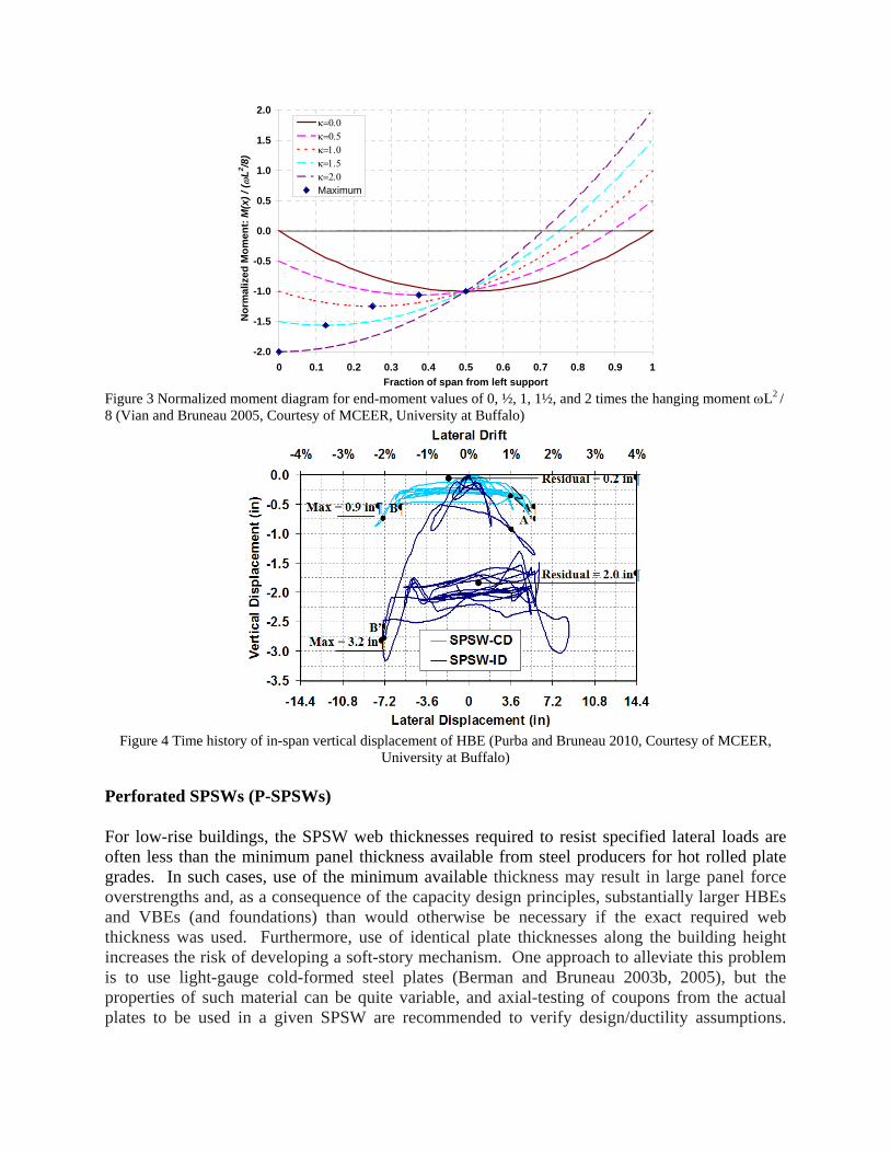
Tubular Eccentrically Braced Frames (TEBFs) All of the original research on EBF was conducted for frames with W-shape beams, and lateral bracing had to be provided at the ends of these links to ensure their stability during large inelastic deformations. However, in some applications, eccentrically braced frames would be desirable in locations where lateral bracing of the link cannot be achieved. In such cases, links with built-up box sections can be used, because such built-up box cross-sections are not susceptible to lateral-torsional buckling. Eccentrically braced frames having such links and without lateral bracing of the link beam have performed in a ductile manner during experiment, provided that specified section compactness requirements are met (Berman and Bruneau 2007, 2008b, 2008c). Note that HSS sections cannot be used for such links, due to concerns about their low cycle fatigue life under large inelastic deformations (see Bruneau et al. 2011). Also note that extremely tall and narrow boxes may not be adequate either, as they can experience lateral-torsional buckling (i.e., buckle about their weak axis); to prevent this undesirable behavior, links of built-up box sections should be sized such that Iy > 0.67Ix, where Iy, is the link’s moment of inertia about an axis in the plane of the EBF, and Ix is the moment of inertia about an axis perpendicular to that plane. External intermediate stiffeners, as in Figure 8, were considered in the experimental and analytical work of Berman and Bruneau (2006; 2008b; 2008c); these were welded to both the webs and the flanges. However, because such stiffeners have no benefit on flange buckling, AISC 341 and CSA S16 do not require them to be connected to the flange. This suggests that intermediate stiffeners could be fabricated inside the built-up box section (which may be desirable for architectural appeal or other reasons).
(a)
(b)
Figure 8 (a) Generic built-up box cross-section with exterior stiffeners; (b) Deformed Link at 0.123 rads Rotation (Berman and Bruneau 2005; Courtesy of MCEER, University at Buffalo)
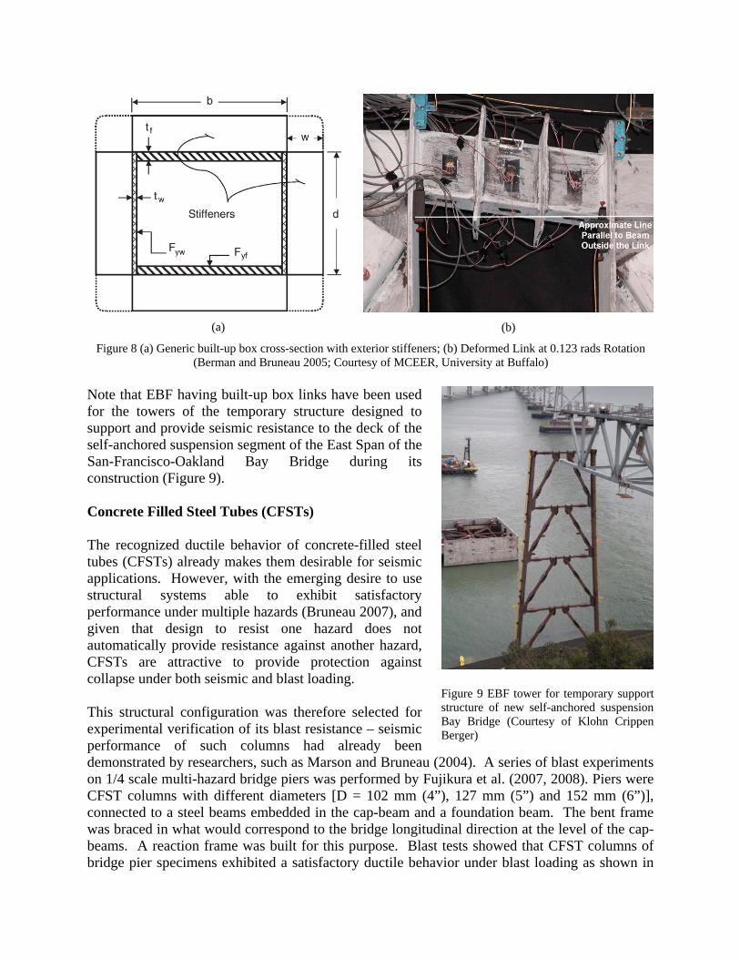
Note that EBF having built-up box links have been used for the towers of the temporary structure designed to support and provide seismic resistance to the deck of the self-anchored suspension segment of the East Span of the San-Francisco-Oakland Bay Bridge during its construction (Figure 9). Concrete Filled Steel Tubes (CFSTs) The recognized ductile behavior of concrete-filled steel tubes (CFSTs) already makes them desirable for seismic applications. However, with the emerging desire to use structural systems able to exhibit satisfactory performance under multiple hazards (Bruneau 2007), and given that design to resist one hazard does not automatically provide resistance against another hazard, CFSTs are attractive to provide protection against collapse under both seismic and blast loading. This structural configuration was therefore selected for experimental verification of its blast resistance – seismic performance of such columns had already been demonstrated by researchers, such as Marson and Bruneau (2004). A series of blast experiments on 1/4 scale multi-hazard bridge piers was performed by Fujikura et al. (2007, 2008). Piers were CFST columns with different diameters [D = 102 mm (4”), 127 mm (5”) and 152 mm (6”)], connected to a steel beams embedded in the cap-beam and a foundation beam. The bent frame was braced in what would correspond to the bridge longitudinal direction at the level of the cap-beams. A reaction frame was built for this purpose. Blast tests showed that CFST columns of bridge pier specimens exhibited a satisfactory ductile behavior under blast loading as shown in
Figure 9 EBF tower for temporary support structure of new self-anchored suspension Bay Bridge (Courtesy of Klohn Crippen Berger)
Figure 10a. The foundation connection concept applied in this experiment allowed to develop the composite strength of the CFST columns under blast loading. Note that for comparison, another test series was conducted to examine the blast resistance of ductile reinforced concrete bridge piers [D = 203 mm (8”)] and non-ductile RC bridge piers retrofitted with steel jackets [D = 213 mm (8 3/8”)] designed according to the current seismic knowledge and detailing provision, as applied in typical highway bridge designs. Out of that test series, standard RC and steel jacketed RC columns were not found to exhibit a ductile behavior under blast loading, failing in direct shear at their base rather than by flexural yielding as was the case with CFST columns (e.g. as in Figure 10-b). Furthermore, this non-ductile failure occurred for a much smaller blast pressure than used for the comparable CFST (Fujikura and Bruneau 2008, 2011, 2012). Reinforced concrete details by current seismic codes and steel jacketing, known to be effective to provide satisfactory seismic performance, were thus shown to be ineffective for the blast loading cases considered. On-going research is investigating the benefits of using Concrete Filled Double Skinned Tubes (CFDSTs as another promising alternative (Fouche and Bruneau 2010). Structural Fuses (SFs) While the term structural fuse has been used extensively in the literature, in a true structural fuse analogy, all damage should concentrate on disposable and easy to repair structural elements (i.e., “structural fuses”), while the main structure is designed to remain elastic (or, at worse, with minor inelastic deformations). Following a severe damaging earthquake, only these special elements would need to be
(a) (b) Figure 10 (a) CFST column (D = 127 mm) after the test; (b) RC column after smaller blast charge test (Fujikura and Bruneau 2007 and 2008; Courtesy of
MCEER, University at Buffalo)
Δya Δyf u
KfKa
K1
αK1 = Kf
Vyf
Vyd
Vy
Vp
V
Frame
Structural Fuses
Total
Figure 11 Sample model of a SDOF system with metallic fuses, and general pushover curve (Vargas and Bruneau 2006a; Courtesy of MCEER, University at Buffalo)
replaced (hence, the “fuse” analogy), making repair works easier and more expedient. Furthermore, in that instance, self-recentering of the structure would occur once the ductile fuse devices are removed, i.e., the elastic structure would return to its original undeformed position. This structural fuse definition is conceptually illustrated in Figure 11 using a general pushover curve for a frame having metallic fuses, represented by elasto-plastic springs acting in parallel. The total curve is tri-linear with the initial stiffness, K1, calculated by adding the stiffness of the frame and the structural fuses, Kf and Ka, respectively. Once the structural fuses reach their yield deformation, Δya, the increment on the lateral force is resisted only by the bare frame, being the second slope of the total curve equal to the frame stiffness, Kf. Vyf and Vyd are the base shear capacity of the bare frame and the structural fuses, respectively; and Vy and Vp are the total system yield strength and base shear capacity, respectively. If system response is maintained to less than Δyf, replacement of the fuse can be achieved with relative ease (as experimentally demonstrated in shake-table tests by Vargas and Bruneau (2006b, 2009) for a three story frame using Buckling Restrained Braces as Structural Fuses). Note that exceeding Δyf is not fatal in terms of life safety when using a relatively ductile “protected” frame; rather, it implies that self-centering upon replacement of the fuse may not occur, and the possible need for repair of the frame. Figure 12 shows a proposed twin column segmental bridge bent implementing SPSLs and BRBs as a series of structural fuses between the columns (2/3 scale specimen). The columns used for the experiment consisted of segments of Bi-Steel sections (Boweman et al 1999).
All specimens tested in this experimental program exhibited stable force-displacement behavior, with little pinching of hysteresis loops until the significant accumulation of damage at large drifts. All specimens performed well, behaving elastically at small displacements and exhibiting stable hysteretic behavior as the seismic energy was dissipated through the structural fuses. Adding the fuses increased both the stiffness and strength of the bare frame about 40% and increased the amount of energy dissipated by the frame (El-Bahey and Bruneau 2012a, 2012b).
(a) (b) (c)
Figure 12 Experiment setup of Structural Fuse Bent (a) with Special Plate Fuses; (b) with Buckling Restrained Brace Fuses; (c) Test Set-up (El-Bahey and Bruneau 2010; Courtesy of MCEER, University at Buffalo)
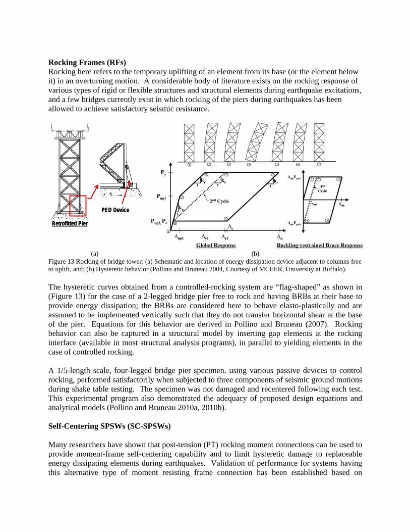
Rocking Frames (RFs) Rocking here refers to the temporary uplifting of an element from its base (or the element below it) in an overturning motion. A considerable body of literature exists on the rocking response of various types of rigid or flexible structures and structural elements during earthquake excitations, and a few bridges currently exist in which rocking of the piers during earthquakes has been allowed to achieve satisfactory seismic resistance.
Retrofitted Pier
PED Device
Retrofitted Pier
PED Device
(a) (b) Figure 13 Rocking of bridge tower: (a) Schematic and location of energy dissipation device adjacent to columns free to uplift, and; (b) Hysteretic behavior (Pollino and Bruneau 2004, Courtesy of MCEER, University at Buffalo). The hysteretic curves obtained from a controlled-rocking system are “flag-shaped” as shown in (Figure 13) for the case of a 2-legged bridge pier free to rock and having BRBs at their base to provide energy dissipation; the BRBs are considered here to behave elasto-plastically and are assumed to be implemented vertically such that they do not transfer horizontal shear at the base of the pier. Equations for this behavior are derived in Pollino and Bruneau (2007). Rocking behavior can also be captured in a structural model by inserting gap elements at the rocking interface (available in most structural analysis programs), in parallel to yielding elements in the case of controlled rocking. A 1/5-length scale, four-legged bridge pier specimen, using various passive devices to control rocking, performed satisfactorily when subjected to three components of seismic ground motions during shake table testing. The specimen was not damaged and recentered following each test. This experimental program also demonstrated the adequacy of proposed design equations and analytical models (Pollino and Bruneau 2010a, 2010b). Self-Centering SPSWs (SC-SPSWs) Many researchers have shown that post-tension (PT) rocking moment connections can be used to provide moment-frame self-centering capability and to limit hysteretic damage to replaceable energy dissipating elements during earthquakes. Validation of performance for systems having this alternative type of moment resisting frame connection has been established based on
analytical and experimental research and shows that these types of systems could be a viable alternative to conventional LFRS systems. Building on this idea, research is being conducted to investigate the potential of achieving Self-Centering Steel Plate Shear Walls (SC-SPSW) by using similar post-tensioned rocking beam connections (Berman et al. 2010, Clayton et al. 2012, Dowden et al. 2012). In this proposed system, the SC-SPSW web plate is the replaceable energy dissipation element, and beam-plastic hinging is eliminated. The system combines the advantages of high lateral stiffness, a substantial energy dissipation capacity, and self-centering capability, at the expense of additional challenges to understanding the flow of forces within the structure compared to conventional SPSW (themselves, more complex than moment frames). Experimental testing of one-third scale single-bay three-story test specimens are currently underway at the University at Buffalo to investigate the system performance of SC-SPSWs (complementarily to tests previously conducted at the University of Washington, Seattle, as part of a collaborative research effort). The full experimental program consists of quasi-static and shake-table testing to investigate SC-SPSW system performance with three different rocking joint configurations. The test specimen and setup is shown in Figure 14. Testing will be done on specimens with HBEs rocking; as well as for a proposed centerline rocking detail and the NewZ-BREAKSS connection developed to eliminate frame expansion during rocking (Dowden and Bruneau 2011).
(a) Test Frame Before Whitewash
(b) Test Set-Up
Figure 14 UB Test Specimen – Photos by Dan Dowden Acknowledgments This work presented here was supported in part by various grants from the National Science Foundation (EERC and NEES Programs), New York State, the Federal Highway Administration, the American Institute of Steel Construction, the Engineer Research and Development Center (ERDC) of the U.S. Army Corps of Engineers, MCEER, NCREE, Star Seismic, and Corus Steel. This support is sincerely appreciated. However, any opinions, findings, conclusions, and recommendations presented in this paper are those of the writer and do not necessarily reflect the views of the sponsors.
References Comprehensive citations of the work of other researchers who contributed to each of the topic covered in this paper are included in some of the papers listed below.
1. AISC. (2005). “Seismic Provisions for Structural Steel Buildings,” ANSI/AISC 341-05, American Institute of Steel Construction Inc., Chicago.
2. AISC. (2010). “Seismic Provisions for Structural Steel Buildings,” ANSI/AISC 341-10, American Institute of Steel Construction Inc., Chicago.
3. Berman, J.W. and Bruneau, M. (2003a). “Plastic Analysis and Design of Steel Plate Shear Walls,” Journal of Structural Engineering, ASCE, 129(11), pp 1448-1456.
4. Berman, J., Bruneau, M., (2003b). “Experimental Investigation of Light-Gauge Steel Plate Shear Walls for the Seismic Retrofit of Buildings”, Technical Report MCEER-03-0001, Multidisciplinary Center for Earthquake Engineering Research, State University of New York at Buffalo, Buffalo, NY, 2003, 163 pages.
5. Berman, J., Bruneau, M., (2006). “Further Development of Tubular Eccentrically Braced Frame Links for the Seismic Retrofit of Braced Steel Truss Bridge Piers”, Technical Report MCEER-06-0006, Multidisciplinary Center for Earthquake Engineering Research, State University of New York at Buffalo, Buffalo, NY, 2006
6. Berman, J., Bruneau, M., (2008a). “Capacity Design of Vertical Boundary Elements in Steel Plate Shear Walls”, AISC Engineering Journal, Vol. 45, No. 1, pp.57-71.
7. Berman, J., Bruneau, M., (2008c). “Tubular Links for Eccentrically Braced Frames, I: Finite Element Parametric Study”, ASCE Journal of Structural Engineering, Vol. 134, No. 5, pp.692-701.
8. Berman, J., Bruneau, M., (2008c). “Tubular Links for Eccentrically Braced Frames, II: Experimental Verification”, ASCE Journal of Structural Engineering, Vol. 134, No. 5,pp.702-712.
9. J. Berman and M. Bruneau (2007). "Experimental and analytical investigation of tubular links for eccentrically braced frames." Engineering Structures 29(8): 1929-1938.
10. Berman, J., Bruneau, M., (2005). “Experimental Investigation of Light-Gauge Steel Plate Shear Walls", ASCE Journal of Structural Engineering, Vol. 131, No.2, pp. 259-267
11. Berman, J, Lowes, L., Bruneau, M., Fahnstock, L., Tsai, K.C., (2010). “An Overview of NEESR-SG: Smart and Resilient Steel Walls for Reducing Earthquake Impacts,” Joint 9th US and 10th Canadian Conference on Earthquake Engineering, Toronto, Canada, July 2010.
12. H. Bowerman, et al. (1999). "Bi-Steel design and construction guide." British Steel Ltd, Scunthorpe (London).
13. Bruneau, M., (2007). "The 4 R's of Resilience and Multi-Hazard Engineering (The Meta-Concept of Resilience)," AEI/MCEER/Steel Institute of NY Symposium on Emerging Developments in Multihazards Engineering. New York City, NY.
14. Bruneau, M. and Bhagwagar, T. (2002). “Seismic Retrofit of Flexible Steel Frames Using Thin Infill Panels,” Engineering Structures, 24(4), 443-453.
15. Bruneau, M., Uang, C.M., Sabelli, R., (2011). “Ductile Design of Steel Structures, 2nd Edition,” McGraw-Hill, New York, 921p.
16. Clayton, P.M., Berman, J.W., Lowes, L.N. (2011). “Seismic Design and Performance of Self-Centering Steel Plate Shear Walls.” ASCE Journal of Structural Engineering (in press).
17. CSA. (2009). “Design of Steel Structures,” CAN/CSA S16-09, Canadian Standards Association, Mississauga, Ontario, Canada.
18. CSA. (2001). “Limit States Design of Steel Structures,” CAN/CSA S16-01, Canadian Standards Association, Willowdale, Ontario, Canada.
19. CSA. (1994). “Limit States Design of Steel Structures,” CAN/CSA S16-94, Canadian Standards Association, Willowdale, Ontario, Canada.
20. Dowden, D., Purba, R., Bruneau, M., (2012). “Behavior of Self-Centering Steel Plate Shear Walls and Design Considerations,” ASCE Journal of Structural Engineering, Vol.138, No.1, (in press).
21. Dowden, D., Bruneau, M., (2011). “NewZ-BREAKSS: Post-tension Rocking Connection Detail Free of Beam-Growth”, AISC Engineering Journal, Vol.48, No2, pp153-158.
22. Driver, R.G., Kulak, G.L., Kennedy, D.J.L. and Elwi, A.E. (1997a). “Seismic Behaviour of Steel Plate Shear Walls,” Structural Engineering Report No. 215, Department of Civil Engineering, University of Alberta, Edmonton, Alberta, Canada.
23. El-Bahey, S., Bruneau, M., (2012a). “Bridge Piers Having Structural Fuses and Bi-steel Columns I: Experimental Testing”, ASCE Journal of Bridge Engineering, Vol.17, No.1, (in press).
24. El-Bahey, S., Bruneau, M., (2012b). “Bridge Piers Having Structural Fuses and Bi-steel Columns II: Analytical Investigation”, ASCE Journal of Bridge Engineering, Vol.17, No.1, (in press).
25. Fouche, P., Bruneau, M., (2010). “Non-Linear Analysis of Multi-Hazard Performance of Concrete Filled Steel Tubes Bridge Piers,” 8th International Conference on Short and Medium Span Bridges, Niagara Falls, Ontario, Canada, August 2010..
26. Fujikura, S., Bruneau M., (2011). “Experimental Investigation of Seismically Resistant Bridge Piers under Blast Loading,” ASCE Journal of Bridge Engineering, Vol.16, No.1, pp.63-71
27. Fujikura, S., Bruneau M., (2012). “Dynamic Analysis of Multi-Hazard Resistant Bridge Piers having Concrete-Filled Steel Tube under Blast Loading,” ASCE Journal of Bridge Engineering, Vol.17, No.2, (in press).
28. Fujikura, S., et al. (2008). "Experimental Investigation of Multihazard Resistant Bridge Piers Having Concrete-Filled Steel Tube under Blast Loading." Journal of Bridge Engineering 13: 586.
29. Fujikura, S. et al. (2007). "Experimental Investigation of Blast Performance of Seismically Resistant Concrete-Filled Steel Tube Bridge Piers," Technical Report MCEER-07-0005, MCEER, University at Buffalo, Buffalo, NY.
30. Fujikura S., and Bruneau, M., (2008). "Experimental Investigation of Blast Performance of Seismically Resistant Reinforced Concrete and Steel Jacketed Bridge Piers," Technical Report MCEER-08-0028, MCEER, University at Buffalo, Buffalo, NY.
31. Kuhn, P., Peterson, J.P. and Levin, L.R. (1952). “A Summary of Diagonal Tension, Part 1—Methods of Analysis,” Tech. Note 2661, National Advisory Committee for Aeronautics, Langley Aeronautical Laboratory, Langley Field, VA.
32. Lee, C.S. and Tsai, K.C. (2008). "Experimental Response of Four 2-Story Narrow Steel Plate Shear Walls" Proceeding of the 2008 Structures Congress. Vancouver, Canada.
33. Lubell, A.S., Prion, H.G.L., Ventura, C.E. and Rezai, M. (2000). “Unstiffened Steel Plate Shear Wall Performance Under Cyclic Loading,” Journal of Structural Engineering, ASCE, 126(4), 453-460.
34. Marson, J., Bruneau, M.,(2004). “Cyclic Testing of Concrete-Filled Circular Steel Bridge Piers Having Encased Fixed-Base Detail”,ASCE Journal of Bridge Engineering, Vol.9, No.1, pp.14-23
35. Montgomery, C.J., Medhekar, M. (2001). Discussion on “Unstiffened Steel Plate Shear Wall Performance Under Cyclic Load,” Journal of Structural Engineering, ASCE, 127(8), 973-973.
36. Qu B. and Bruneau, M., (2008). “Seismic Behavior and Design of Boundary Frame Members in Steel Plate Shear Walls”, Technical Report MCEER-08-0012, Multidisciplinary Center for Earthquake Engineering Research, State University of New York at Buffalo, Buffalo, NY, 2008.
37. Qu, B., Bruneau, M., (2010a). “Capacity Design of Intermediate Horizontal Boundary Elements of Steel Plate Shear Walls”, ASCE Journal of Structural Engineering, Vol.136, No.6, pp. 665-675
38. Qu, B., Bruneau, M.,(2010b). “Behavior of Vertical Boundary Elements in Steel Plate Shear Walls”, AISC Engineering Journal, Vol.47, No.2, pp.109-122
39. Qu, B., Bruneau, M.,(2011). “Plastic Moment of Intermediate Horizontal Boundary Elements of Steel Plate Shear Walls”, AISC Engineering Journal, Vol.48, No.1, pp.49-64.
40. Pollino, M., Bruneau, M., (2004). “Seismic Retrofit of Bridge Steel Truss Piers using a Controlled Rocking Approach”, Technical Report MCEER-04-0011, Multidisciplinary Center for Earthquake Engineering Research, State University of New York at Buffalo, Buffalo, NY, 2004.
41. Pollino, M., Bruneau, M., (2007). “Seismic Retrofit of Bridge Steel Truss Piers Using a Controlled Rocking Approach”, ASCE Journal of Bridge Engineering, Vol.12, No.5, pp.600-610
42. Pollino, M., Bruneau, M., (2010a). “Bi-Directional Behavior and Design of Controlled Rocking 4-Legged Bridge Steel Truss Piers,” ASCE Journal of Structural Engineering, Vol.136, No.12, pp.1512-1522.
43. Pollino, M., Bruneau, M., (2010b). “Seismic Testing of a Bridge Truss Pier Designed for Controlled Rocking,” ASCE Journal of Structural Engineering, Vol.136, No.12, pp.1523-1532.
44. Purba, R., Bruneau, M., (2012). “Case Study on the Impact of Horizontal Boundary Elements Design on Seismic Behavior of Steel Plate Shear Walls,” ASCE Journal of Structural Engineering (in press).
45. Purba, R. and Bruneau, M. (2007), “Design Recommendations for Perforated Steel Plate Shear Walls”, Technical Report MCEER-07-0011, MCEER, University at Buffalo, Buffalo, NY
46. Purba, R., Bruneau, M., (2009). “Finite Element Investigation and Design Recommendations for Perforated Steel Plate Shear Walls”, ASCE Journal of Structural Engineering, Vol.135, No.11, pp.1367-1376.
47. Purba, R., Bruneau, M., (2010). “Impact of Horizontal Boundary Elements Design on Seismic Behavior of Steel Plate Shear Walls,” Technical Report MCEER-10-0007, MCEER, University at Buffalo, Buffalo, NY.
48. Sabelli, R., Bruneau, M., (2007). “Steel Plate Shear Walls (AISC Design Guide)”, American Institute of Steel Construction, Chicago, Illinois, 144 p.
49. Vian, D., Bruneau, M., (2005). “Steel Plate Walls for Seismic Design and Retrofit of Building Structures”, Technical Report MCEER-05-0010, Multidisciplinary Center for Earthquake Engineering Research, State University of New York at Buffalo, NY.
50. Vian D., Bruneau, M., Tsai, K.C., Lin, Y.C., (2009). “Special Perforated Steel Plate Shear Walls with Reduced Beam Section Anchor Beams I: Experimental Investigation”, ASCE Journal of Structural Engineering, Vol.135, No.3, pp.211-220.
51. Vian D., Bruneau, M., Purba, R., (2009). “Special Perforated Steel Plate Shear Walls with Reduced Beam Section Anchor Beams II: Analysis and Design Recommendations”, ASCE Journal of Structural Engineering, Vol.135, No.3, pp.221-228.
52. Vargas, R., Bruneau, M., (2006a). “Experimental Investigation of the Structural Fuse Concept”, Technical Report MCEER-06-0005, Multidisciplinary Center for Earthquake Engineering Research, State University of New York at Buffalo, Buffalo, NY, 2006.
53. Vargas, R., Bruneau, M., (2006b). “Analytical Investigation of the Structural Fuse Concept”, Technical Report MCEER-06-0004, Multidisciplinary Center for Earthquake Engineering Research, State University of New York at Buffalo, Buffalo, NY, 2006.
54. Vargas, R., Bruneau, M., (2009). “Experimental Response of Buildings Designed with Metallic Structural Fuses”, ASCE Journal of Structural Engineering, Vol.135, No.4, pp.394-403.
55. Wagner, H. (1931). “Flat Sheet Metal Girders with Very Thin Metal Webs. Part I-General Theories and Assumptions, and Part III: Sheet Metal Girders with Spars Resistant to Bending – The Stress in Uprights – Diagonal Tension Fields." Technical Memorandum Nos.604 and 606, National Advisory Committee for Aeronautics, Washington, D.C.