Page 1
Published in: Journal of Constructional Steel Research, 67(10), 1537-1544.
DOI: http://dx.doi.org/10.1016/j.jcsr.2011.03.028
1
Steel silos with different aspect ratios:
I – behaviour under concentric discharge
A.J. Sadowski & J.M. Rotter
Abstract
The current European standards for the design of thin-walled metal silos require the
designer to use a complex combination of rules covering many different aspects of
loading, structural behaviour and strength. Each individual rule was often developed
autonomously, usually with implicit and undocumented conservative assumptions.
When combined, the overall factor of safety of a designed silo may be significantly
different from that guaranteed by the standard, making it difficult to reproduce the
design rules in a numerical calculation that does not include the same implicit
assumptions.
This paper explores the behaviour of five thin-walled cylindrical silos with stepwise-
varying wall thickness and aspect ratios varying from very squat to very slender, all
custom-designed for and analysed under the EN 1991-4 (2006) concentric discharge
loading condition. The aspect ratio plays a deciding role in both the behaviour and
design of silos, and it is important to ascertain that a finding that is valid for one is
transferable to the others. The nonlinear finite element analyses reveal that the
computed load factor exceeds the partial safety factor in design by a large factor over
a wide range of aspect ratio, suggesting that the overall design process is particularly
conservative. The reasons for these discrepancies are explored.
This paper is the first of a pair. The second paper explores the behaviour of the same
set of example silos under the EN 1991-4 eccentric discharge loads, with
fundamentally different conclusions.
Keywords: concentric discharge, silos, shell buckling, plasticity, aspect ratio, design
of steel structures.
Page 2
Published in: Journal of Constructional Steel Research, 67(10), 1537-1544.
DOI: http://dx.doi.org/10.1016/j.jcsr.2011.03.028
2
1. Introduction
The design of thin-walled metal silos is a complex process that pieces together many
different structural considerations. The current design rules for the strength and
stability of shell structures are those of the European standard EN 1993-1-6 (2007),
while the design of silos specifically is covered by load cases given in EN 1991-4
(2006) and strength design requirements in EN 1993-4-1 (2007). Together, these three
standards define the loading on the structure, the relationship between loading and
resistance and finally the calculations that attempt to safely predict the resistance of
the structure itself, taking into account the many different possible mechanisms of
failure, but especially buckling. Furthermore, individual design rules for each part of
the entire assessment are usually developed autonomously and often with implicitly
assumed margins of safety to account for uncertainty or experimental scatter. When a
collection of these rules is invoked to design a structure, its actual margin of safety
may be different from what is notionally assumed in the standard. Thus the empirical
origin of many of the EN design rules presents significant problems in the calibration
of the design rules with a numerical calculation.
In cylindrical silos under concentric discharge, axial compression in the silo wall is
caused by friction between the wall and the stored granular solid. The compressive
axial membrane stress resultant is cumulative with depth, so that the risk of buckling
is substantially increased towards the base of the silo. Further, it is widely recognised
that the buckling strength of a shell under axial compression is adversely sensitive to
the amplitude and form of geometric imperfections in the wall (Koiter, 1945; 1963;
Yamaki, 1984; Rotter, 1998; 2004). Conversely, the internal pressure and the tensile
circumferential membrane stress resultant both tend to a constant asymptotic value at
some large depth, so that the risk of bursting does not increase beyond a certain depth
The design buckling strength is almost universally expressed in the form ασcr where α
is a ‘knock-down’ factor (0 < α ≤ 1) which attempts to account for the detrimental
effect of geometric imperfections and σcr is the ‘classical elastic critical buckling
stress’ for the reference case of uniform axial compression. The EN 1993-1-6 (2007)
standard enhances this relationship to allow the cylinder to benefit from the
strengthening effect of internal pressure, but also ensures that the design is penalised
Page 3
Published in: Journal of Constructional Steel Research, 67(10), 1537-1544.
DOI: http://dx.doi.org/10.1016/j.jcsr.2011.03.028
3
if the pressure is too high. However, there are some important effects which are not
yet included in the hand-design rules, notably the restraint provided by a thicker lower
plate at the base of a wall strake (Rotter and Teng, 1989), collapse near a boundary
(Rotter, 1998) or the stiffening effect of the elastic restraint provided by the stationary
granular solid inside the silo (Rotter and Zhang, 1990; Knödel et al., 1995).
This paper presents a significant enhancement and development of two previous
studies by the authors (Sadowski & Rotter, 2010; 2011). In each of these, the authors
investigated the behaviour of a single metal silo of different aspect ratio in the slender
range designed explicitly for concentric discharge pressures according to the
structural assessment of EN 1993-1-6 and EN 1993-4-1. These were both introductory
studies and the first of their kind to investigate and compare the structural
consequences of the EN 1991-4 concentric and eccentric discharge load definitions
directly. They explored the mechanics of the complex behaviour under these load
cases, but it was impossible to present the full findings due to the complexity of the
phenomena involved. As a shared conclusion, it was found that the predicted buckling
strength of the silo under concentric discharge pressures was higher than that
prescribed by the EN standard by a factor of approximately two when analysed with a
nonlinear finite element analysis. Although this finding suggests a highly conservative
design procedure, it is unsafe to assume that this will always be the case until silos of
different aspect ratios have been studied. This is because the aspect ratio plays an vital
role in both the behaviour and design of silos, and a finding for one aspect ratio is
often not transferable to another.
The aim of this paper is to investigate the validity of the conservatism of the design
process for metal silos of different aspect ratio, and to give a deeper insight into the
associated behaviour which could not be seen in the authors' earlier papers. Since EN
1991-4 makes very substantial distinctions between silos of different aspect ratio, it is
not safe to conclude that the above finding for a single structure is truly representative
of all aspect ratios. This is particularly evident when it is recognised that slender silos
are subject to a relatively low internal pressure but high axial compression, whilst
squat silos on the contrary experience high internal pressure but rather small axial
compression. This paper therefore explores the above discrepancy between the EN
hand-design rules and a finite element prediction by investigating five custom-
Page 4
Published in: Journal of Constructional Steel Research, 67(10), 1537-1544.
DOI: http://dx.doi.org/10.1016/j.jcsr.2011.03.028
4
designed metal silos. The silos were chosen to have aspect ratios ranging from very
squat to very slender in order to explore the range over which the finding of the
previous study remains valid. Areas of the design process which may require
modification are identified and discussed.
2. Design of five example silos of different aspect ratio
The European standard on actions on silos and tanks EN 1991-4 (2006) classifies silos
solely on the basis of their aspect ratio (height over diameter, H/D). This is because
the aspect ratio significantly influences the relative magnitudes and patterns of normal
pressure (ph) and frictional tractions (pw) exerted by the stored granular solid on the
silo wall (Eqs 1 to 3), and consequently also the structural behaviour of the silo. The
classification criteria according to the silo aspect ratio defined by EN 1991-4 are
presented in Table 1.
Table 1 – Summary of slenderness categories according to EN 1991-4 (2006)
Aspect ratio
range
Axisymmetric
pressure distribution
Silo slenderness
category
H/D ≥ 2.0 Janssen Slender
1.0 < H/D < 2.0 Modified Reimbert Intermediate slender
0.4 < H/D ≤ 1.0 Modified Reimbert Squat
H/D ≤ 0.4 Geostatic Retaining silo (flat bottom)
Janssen (H/D ≥ 2.0): ( ) ( )0/0 1
z zh hp z p e
−= − (1)
Modified Reimbert (0.4 < H/D < 2.0): ( ) 00
0 0
1 1
n
h h
z hp z p
z h
− = − + −
(2)
Geostatic (H/D ≤ 0.4): ( ) ( )1 sinh rp z K zγ φ= + (3)
where 02
Rz
Kµ= , 0 0hp K zγ= and ( ) 0
0
1 tan 1r
hn
zφ
= − + −
. R is the silo radius, K
and µ are the lateral pressure ratio and the fully-developed wall friction coefficient
between the granular solid and the wall respectively, γ and rφ are the unit weight and
angle of repose of the granular solid respectively and h0 is the height between the
Page 5
Published in: Journal of Constructional Steel Research, 67(10), 1537-1544.
DOI: http://dx.doi.org/10.1016/j.jcsr.2011.03.028
5
equivalent surface of the solid and the highest solid to wall contact. The associated
frictional tractions are defined according to the usual relation pw = µph.
For the purposes of this study, five steel silos were designed with different aspect
ratios in the range 0.65 ≤ H/D ≤ 5.20 and stepwise-varying wall thickness, in a
manner similar to Sadowski & Rotter (2010; 2011). The designs were made to support
the symmetrical loads arising from the storage of approximately 510 m3
of a generic
material whose properties may be considered to be similar to those of wheat, which
are representative of a wide range of different granular solids. The properties of the
material were therefore taken from Annex E of EN 1991-4 as those of wheat,
assuming fully-developed wall friction properties for a D2 ‘smooth’ wall.
Table 2 – Summary of the parameters of the five example silos
Design silo name
(Acronym)
H
(m)
D
(m)
H/D Storage
volume
(m3)
Steel
volume
(m3)
Rating†
capacity
(t)
Loading†
capacity
(t)
Pressure
distribution
Very Slender (VS) 26.0 5.0 5.20 510.5 1.91 390.3 468.4 Janssen
Slender (S) 18.0 6.0 3.00 508.9 1.41 389.1 466.9 Janssen
Boundary (B) 14.0 6.8 2.06 508.4 1.12 388.7 466.5 Janssen
Intermediate (I) 11.2 7.6 1.47 508.1 0.89 388.4 466.1 Mod. Reimbert
Squat (Q) 6.5 10.0 0.65 510.5 0.32 390.3 468.4 Mod. Reimbert
Note (†): the lower characteristic value of the unit weight of the solid is used for
rating the capacity of the silo to determine the Action Assessment Class; the higher
characteristic value is used to calculate the actions on the silo (EN 1991-4, 2006:
Annex E).
The silos were assumed to be flat-bottomed with no hopper. The aspect ratios were
chosen so that the volume and capacity of each silo was approximately equal whilst
maintaining simple overall dimensions. As a result, each such silo of different aspect
ratio may be considered to be a plausible alternative design to the same storage
requirement and is analysed in this wider context, as opposed to Sadowski & Rotter
(2010; 2011) where only two slender silos (H/D > 2) were studied in total. The key
parameters of each silo design are summarised in Table 2. For ease of identification,
Page 6
Published in: Journal of Constructional Steel Research, 67(10), 1537-1544.
DOI: http://dx.doi.org/10.1016/j.jcsr.2011.03.028
6
each silo was assigned a name and an acronym reflecting its slenderness category
according to EN 1991-4 (see Table 1). The material properties for mild steel were
assumed as: yield stress = 250 MPa, Poisson’s ratio = 0.3 and elastic modulus = 200
GPa. A preliminary investigation of Silo S (H/D = 3) on its own was previously
presented in Sadowski & Rotter (2010).
Fig. 1 – Axial distribution of normalised normal pressures for each silo design under
concentric discharge, assuming the maximum pressure case for bursting
The structural design was carried out according to EN 1993-1-6 (2007) and EN 1993-
4-1 (2007), using the concentric discharge pressures from EN 1991-4 (2006) under
the maximum friction load case, which is the critical case for buckling under axial
compression (Fig. 1). Action Assessment Class 2 was assumed based on the rated
capacity and no filling or discharge eccentricity. The requirement for an
unsymmetrical patch load was omitted to clarify the interpretation of the calculations.
The EN 1991-4 discharge factors for normal pressures and frictional tractions, Ch and
Cw, were taken as 1.15 and 1.1 respectively for every silo design (including Silo Q) to
be consistent, though EN 1991-4 does not require discharge factors for squat silos.
The partial safety factor for unfavourable structural actions and the resistance partial
safety factor for stability, γF and γM1, were taken as 1.5 and 1.1 respectively (EN 1993-
Page 7
Published in: Journal of Constructional Steel Research, 67(10), 1537-1544.
DOI: http://dx.doi.org/10.1016/j.jcsr.2011.03.028
7
4-1, 2007), giving an overall safety factor of 1.5 × 1.1 = 1.65 for the hand design
calculations. This assumed value (1.65) will be compared with the computed load
proportionality factor from a finite element calculation to obtain a realistic measure of
the actual margin of safety of the designed structure.
In EN 1993-1-6, the effects of geometric imperfections are accounted for by a ‘knock-
down’ factor α for buckling. This factor is modified to account for the effect of
internal pressure, which can be either beneficial elastic stabilisation and detrimental
plastic destabilisation, depending on the relative magnitude of the local internal
pressure. For all silos, regardless of aspect ratio, the internal pressure was found to be
beneficial to the buckling strength of the local wall strake, reducing the detrimental
effect of imperfections and allowing α = αpe to be used in design (Eq. 4). Note that EN
1993-1-6 requires that αpe be calculated using the ‘smallest design value of local
internal pressure that can be guaranteed to coexist with the meridional compression’,
which in the present context means unfactored filling pressures (EN 1991-4, 2006).
Consequently, finite element analyses which use the higher factored discharge
pressures will inevitably predict a higher strength gain due to internal pressure than
that which can be assumed in the hand-design procedure. This is a discrepancy in the
EN 1993-4-1 standard which needs to be addressed.
( )0 0 0.50
10.3
pe
p
pα α α
α −
= + −
+ (4)
where filling
cr
p Rp
tσ= ,
1kw R
t Q t
∆= and α0 is the unpressurised imperfection reduction
factor (αpe > α0), given by:
( )0 1.44
0.62
1 1.91 /kw tα =
+ ∆ (5)
In the above, σcr is the classical elastic critical buckling stress (≈ 0.605Et/R) and ∆wk
is the characteristic imperfection amplitude, taken as the hand-design value from EN
1993-1-6 (2007) Annex D for Fabrication Tolerance Quality Class C (see Table 3).
The strength reduction caused by an imperfection depends on its amplitude relative to
the local wall thickness (δ/t), but the prescribed imperfection amplitudes of EN 1993-
1-6 are larger as the radius to thickness (R/t) ratio increases. As a result, the thin upper
Page 8
Published in: Journal of Constructional Steel Research, 67(10), 1537-1544.
DOI: http://dx.doi.org/10.1016/j.jcsr.2011.03.028
8
strakes in each silo design have larger defined imperfections relative to the wall
thickness (Table 3), though they are smaller in absolute geometric terms.
Table 3 – Summary of characteristic imperfection amplitudes to be used in hand-
based design (EN 1993-1-6, 2007; Annex D), adopted here in all analyses
Wall
thickness
(mm)
∆wk, units of local wall thickness
Silo VS
(H/D =
5.20)
Silo S
(H/D =
3.00)
Silo B
(H/D =
2.06)
Silo I
(H/D =
1.47)
Silo Q
(H/D =
0.65)
1 – – – – 4.419
2 – – – – 3.125
3 1.804 1.976 2.104 2.224 2.552
4 1.563 1.712 1.822 1.926 –
5 1.398 1.531 1.630 1.723 –
6 1.276 1.398 1.488 – –
7 1.181 – – – –
Silos with higher aspect ratios require significantly thicker walls than squatter silos
because friction between the solid and the silo wall develops very high axial
compression throughout the entire height of the silo, which is furthermore cumulative
with depth (Fig. 2). Conversely, the circumferential membrane tension caused by
normal pressure which tends towards a constant asymptotic value (ph0, Fig. 1). The
walls of each silo were made just thick enough at the base of each strake to meet the
design requirements with respect to buckling, regardless of practical steel sheet sizes.
The points at which the plate thickness changes consequently all become equally
critical locations for buckling under the axisymmetric loading conditions (Fig. 2), so
the numerical analyses which follow might therefore be expected to identify many
buckling modes at different points with very similar load factors. Note that the wall
thicknesses required to withstand buckling failure were always found to be far greater
than those required to withstand simple bursting by rupture (Fig. 3), though this
difference was smaller for squatter silos where the axial compression was much
lower. Thus buckling considerations play a very important role in the design of silos
of all aspect ratios. Lastly, the relative slenderness λ according to EN 1993-1-6 (the
square root of the ratio of plastic collapse load to critical elastic buckling stress) was
Page 9
Published in: Journal of Constructional Steel Research, 67(10), 1537-1544.
DOI: http://dx.doi.org/10.1016/j.jcsr.2011.03.028
9
always found to be above the plastic limit relative slenderness λp, so that the hand-
design procedure actually predicted elastic buckling for all silos.
Fig. 2 – Axial distribution of the design (compressive) axial membrane stress
resultants and design resistances for each example silo
Fig. 3 – Axial distribution of required design thicknesses to resist bursting and
buckling for each example silo
Page 10
Published in: Journal of Constructional Steel Research, 67(10), 1537-1544.
DOI: http://dx.doi.org/10.1016/j.jcsr.2011.03.028
10
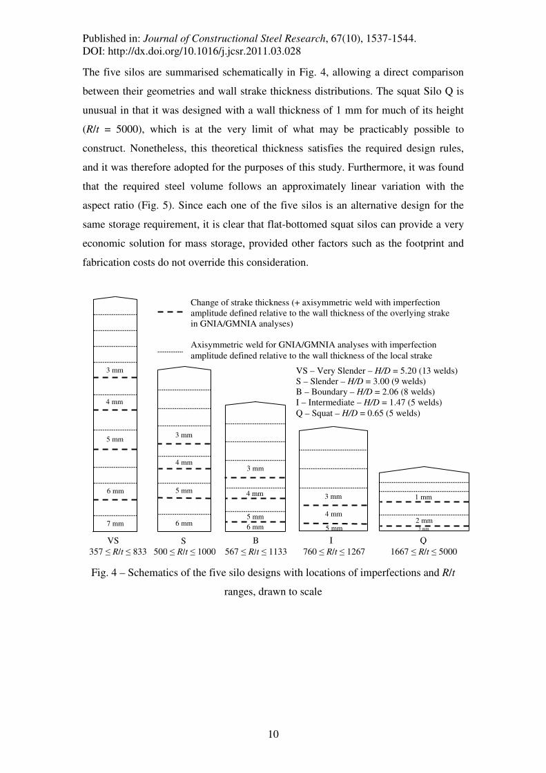
The five silos are summarised schematically in Fig. 4, allowing a direct comparison
between their geometries and wall strake thickness distributions. The squat Silo Q is
unusual in that it was designed with a wall thickness of 1 mm for much of its height
(R/t = 5000), which is at the very limit of what may be practicably possible to
construct. Nonetheless, this theoretical thickness satisfies the required design rules,
and it was therefore adopted for the purposes of this study. Furthermore, it was found
that the required steel volume follows an approximately linear variation with the
aspect ratio (Fig. 5). Since each one of the five silos is an alternative design for the
same storage requirement, it is clear that flat-bottomed squat silos can provide a very
economic solution for mass storage, provided other factors such as the footprint and
fabrication costs do not override this consideration.
Fig. 4 – Schematics of the five silo designs with locations of imperfections and R/t
ranges, drawn to scale
VS – Very Slender – H/D = 5.20 (13 welds)
S – Slender – H/D = 3.00 (9 welds)
B – Boundary – H/D = 2.06 (8 welds)
I – Intermediate – H/D = 1.47 (5 welds)
Q – Squat – H/D = 0.65 (5 welds)
S
3 mm
4 mm
5 mm
6 mm
VS
3 mm
4 mm
5 mm
6 mm
7 mm
B
3 mm
4 mm
5 mm
6 mm
I
5 mm
3 mm
4 mm
Q
2 mm
1 mm
3 mm
Change of strake thickness (+ axisymmetric weld with imperfection
amplitude defined relative to the wall thickness of the overlying strake
in GNIA/GMNIA analyses)
Axisymmetric weld for GNIA/GMNIA analyses with imperfection
amplitude defined relative to the wall thickness of the local strake
357 ≤ R/t ≤ 833 500 ≤ R/t ≤ 1000 567 ≤ R/t ≤ 1133 760 ≤ R/t ≤ 1267 1667 ≤ R/t ≤ 5000
Page 11
Published in: Journal of Constructional Steel Research, 67(10), 1537-1544.
DOI: http://dx.doi.org/10.1016/j.jcsr.2011.03.028
11
Fig. 5 – Variation of the required steel volume with aspect ratio for the silo cylinder
3. Numerical analysis
The example silos were modelled using the commercial finite element package
ABAQUS (2009) under the concentric discharge condition. Using appropriate
boundary conditions, only a quarter of the silo was modelled with nine-node reduced-
integration S9R5 shell elements. The mesh resolution was increased near changes of
plate thickness, at locations of weld imperfections and at the bottom pinned boundary.
The top boundary consisted of a conical roof of inclination 15° to the horizontal
which was modelled using four-node S4R5 shell elements for each silo. The
significance of modelling the roof as a boundary condition is made clear in the
companion paper on eccentric discharge. When analysing the imperfect shell,
axisymmetric weld depressions of Type A (Rotter and Teng, 1989) were introduced at
several locations on each silo, including at every change of plate thickness (Fig. 4).
The imperfection amplitude was always chosen as that of the hand design calculations
(∆wk, see Table 3). The same material properties for mild steel were used.
Page 12
Published in: Journal of Constructional Steel Research, 67(10), 1537-1544.
DOI: http://dx.doi.org/10.1016/j.jcsr.2011.03.028
12
4. Nonlinear load-deflection behaviour
The complete set of alternative computational shell calculations according to EN
1993-1-6 (2007) was performed on each silo, summarised in Table 4. Where
applicable, the load-deflection path of a node on the silo-roof boundary was followed
with the modified Riks (1979) procedure.
Table 4 – Summary of EN 1993-1-6 (2007) computational analyses used in this study
Analysis
acronym
Geometry Material
relation
Presence of
imperfections
Objective of analysis
LA Linear Linear No Reference linear-elastic stresses
LBA Linear Linear No First buckling eigenvalue & mode
MNA Linear Nonlinear No Reference plastic collapse load
GNA Nonlinear Linear No Lowest buckling load & mode
GMNA Nonlinear Nonlinear No Lowest buckling load & mode
GNIA Nonlinear Linear Yes Lowest buckling load & mode
GMNIA Nonlinear Nonlinear Yes Lowest buckling load & mode
Fig. 6 – Load-deflection paths for Silo VS under concentric discharge showing
unstable post-buckling behaviour, typical of shells under axisymmetric loads
Page 13
Published in: Journal of Constructional Steel Research, 67(10), 1537-1544.
DOI: http://dx.doi.org/10.1016/j.jcsr.2011.03.028
13
The nonlinear load-deflection paths for the very slender Silo VS are shown in Fig. 6
and clearly illustrate the differences between the different analyses. Specifically, the
figure shows that the GNA-based analyses predict dramatic bifurcation buckling
followed by a reversal of the equilibrium path, with a noticeable loss of linear
stiffness when axisymmetric weld depressions are included. The remaining four silos
all exhibited very similar nonlinear load-deflection paths under concentric discharge,
for which the same observations can be made. In all cases, the inclusion of either
geometric nonlinearity, material plasticity or imperfections resulted in progressively
increased strength reductions. These reductions were found to be greatest for the
slender silos.
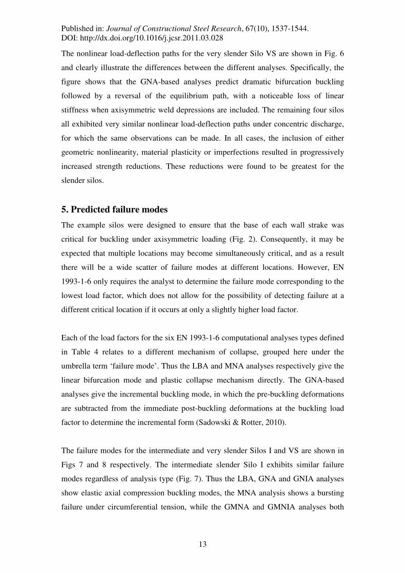
5. Predicted failure modes
The example silos were designed to ensure that the base of each wall strake was
critical for buckling under axisymmetric loading (Fig. 2). Consequently, it may be
expected that multiple locations may become simultaneously critical, and as a result
there will be a wide scatter of failure modes at different locations. However, EN
1993-1-6 only requires the analyst to determine the failure mode corresponding to the
lowest load factor, which does not allow for the possibility of detecting failure at a
different critical location if it occurs at only a slightly higher load factor.
Each of the load factors for the six EN 1993-1-6 computational analyses types defined
in Table 4 relates to a different mechanism of collapse, grouped here under the
umbrella term ‘failure mode’. Thus the LBA and MNA analyses respectively give the
linear bifurcation mode and plastic collapse mechanism directly. The GNA-based
analyses give the incremental buckling mode, in which the pre-buckling deformations
are subtracted from the immediate post-buckling deformations at the buckling load
factor to determine the incremental form (Sadowski & Rotter, 2010).
The failure modes for the intermediate and very slender Silos I and VS are shown in
Figs 7 and 8 respectively. The intermediate slender Silo I exhibits similar failure
modes regardless of analysis type (Fig. 7). Thus the LBA, GNA and GNIA analyses
show elastic axial compression buckling modes, the MNA analysis shows a bursting
failure under circumferential tension, while the GMNA and GMNIA analyses both
Page 14
Published in: Journal of Constructional Steel Research, 67(10), 1537-1544.
DOI: http://dx.doi.org/10.1016/j.jcsr.2011.03.028
14
show an elastic-plastic elephant’s foot buckling mode. In each of these analyses,
failure is predicted to occur at the base of the thinnest 3 mm wall strake. The
similarity of these failure modes reflects the fact that the range of load factors for Silo
I is not very wide, varying from 5.55 to 3.09 for LBA to GMNIA respectively.
Fig. 7 – Failure modes for the rather squat Intermediate Silo I (H/D = 1.47),
characteristic of the squatter silos analysed in this study
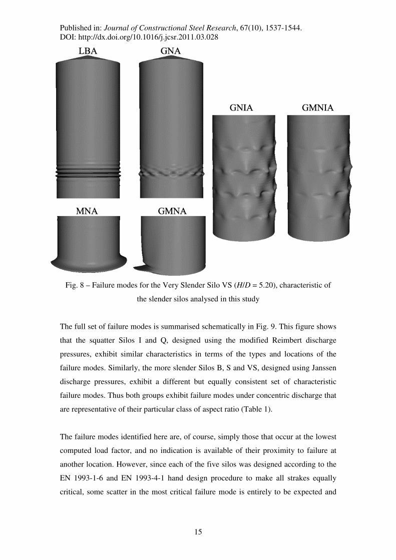
By contrast, the very slender Silo VS exhibits a more varied set of failure modes (Fig.
8). The LBA and GNA analyses predict similar elastic axial compression buckling
modes. However, the MNA analysis shows a yielding failure under the combination
of circumferential tension and axial compression at the base of the silo, while the
GMNA analysis shows a localised elastic-plastic elephant’s foot buckle. The GNIA
and GMNIA analyses show global diamond buckling modes with interesting signs of
interactions between the adjacent weld depressions leading to a lower buckling
strength (Rotter, 1996; Pircher and Bridge, 2000). The differing locations and
character of these failure modes reflects the range of load factors from LBA to
GMNIA, varying from 9.07 to 3.77 respectively for Silo VS.
Page 15
Published in: Journal of Constructional Steel Research, 67(10), 1537-1544.
DOI: http://dx.doi.org/10.1016/j.jcsr.2011.03.028
15
Fig. 8 – Failure modes for the Very Slender Silo VS (H/D = 5.20), characteristic of
the slender silos analysed in this study
The full set of failure modes is summarised schematically in Fig. 9. This figure shows
that the squatter Silos I and Q, designed using the modified Reimbert discharge
pressures, exhibit similar characteristics in terms of the types and locations of the
failure modes. Similarly, the more slender Silos B, S and VS, designed using Janssen
discharge pressures, exhibit a different but equally consistent set of characteristic
failure modes. Thus both groups exhibit failure modes under concentric discharge that
are representative of their particular class of aspect ratio (Table 1).
The failure modes identified here are, of course, simply those that occur at the lowest
computed load factor, and no indication is available of their proximity to failure at
another location. However, since each of the five silos was designed according to the
EN 1993-1-6 and EN 1993-4-1 hand design procedure to make all strakes equally
critical, some scatter in the most critical failure mode is entirely to be expected and
Page 16
Published in: Journal of Constructional Steel Research, 67(10), 1537-1544.
DOI: http://dx.doi.org/10.1016/j.jcsr.2011.03.028
16
supports the hand design rules as giving a relatively uniform safety factor throughout.
Consequently, it is not possible to read too much into the calculated failure locations.
Fig. 9 – Summary schematic of predicted failure mode locations at the lowest load
factor for the five silos analysed under concentric discharge, drawn to scale
6. Analysis of load proportionality factors
The computed EN 1993-1-6 load proportionality factors for the five example silos are
summarised in Table 5 and plotted against the aspect ratio in Fig. 10. In all of the
present analyses, the LBA and GNA predictions are very close, suggesting that the
silo behaviour exhibits a high degree of linearity under concentric discharge. The
MNA factors are well below those for LBA or GNA in the slender aspect ratio range,
though the two sets of curves become closer to each other with decreasing aspect ratio
and eventually intersect at approximately H/D = 1.5. Thus slender silos under
concentric discharge may be expected to exhibit predominantly plastic buckling
behaviour, whilst squat silos are more likely to exhibit predominantly elastic buckling
behaviour. This is confirmed by the relatively large drop in load factor from GNA to
GMNA for slender silos, but not for squatter silos. Also, the GNIA and GMNIA load
GMNIA
S
3 mm
4 mm
5 mm
6 mm
LBA
MNA
GNA
GMNA
GNIA
B
3 mm
4 mm
5 mm
6 mm
LBA
MNA
GNA
GMNA
GNIA
GMNIA
I
5 mm
3 mm
4 mm
All analyses
MNA
VS
3 mm
4 mm
5 mm
6 mm
7 mm
LBA
GNA
GNIA
GMNIA
GMNA
Q
2 mm
1 mm
3 mm
All analyses
VS – Very Slender – H/D = 5.20
S – Slender – H/D = 3.00
B – Boundary – H/D = 2.06
I – Intermediate – H/D = 1.47
Q – Squat – H/D = 0.65
Axisymmetric elastic buckle (LBA, GNA &
GNIA), plastic bursting mode (MNA) or
elastic-plastic elephant’s foot buckling mode
(GMNA & GMNIA), localised near a
boundary.
Global diamond buckling mode spanning
several wall strakes (GNIA & GMNIA only).
Localised elastic-plastic elephant’s foot
buckling mode at a boundary (GMNA &
GMNIA only).
Page 17
Published in: Journal of Constructional Steel Research, 67(10), 1537-1544.
DOI: http://dx.doi.org/10.1016/j.jcsr.2011.03.028
17
factors are always lower than all of the others, which shows that the axisymmetric
weld imperfection is very deleterious to the predicted buckling strength, and may well
be the most damaging realistic imperfection form for a silo for this load condition, as
suggested by Rotter (2004).
Table 5 – Summary of the predicted load factors under concentric discharge
Analysis Silo VS
(H/D =
5.20)
Silo S
(H/D =
3.00)
Silo B
(H/D =
2.06)
Silo I
(H/D =
1.47)
Silo Q
(H/D =
0.65)
LBA 9.07 7.85 6.97 5.55 1.79
MNA 6.43 6.89 6.64 5.65 2.48
GNA 8.90 7.77 6.93 5.55 1.76
GMNA 5.11 4.91 5.55 4.70 1.60
GNIA 4.40 5.62 4.55 4.57 1.58
GMNIA 3.77 3.99 3.75 3.09 1.28
Fig. 10 – Plot of the load proportionality factors as a function of the silo aspect ratio
It is important that the shell analyst ascertains whether the failure mode will indeed be
elastic or plastic, as this will influence the decision on whether to spend resources on
Page 18
Published in: Journal of Constructional Steel Research, 67(10), 1537-1544.
DOI: http://dx.doi.org/10.1016/j.jcsr.2011.03.028
18
a higher steel grade with a higher yield stress. Thus it may be worthwhile to invest in
a stronger grade of steel for slender silos, which in this case would place the MNA
curve above those of LBA or GNA, and equate the GNIA and GMNIA curves.
However, for aspect ratios below approximately H/D = 1.5, the use of higher practical
grade of steel is unlikely to serve any purpose given the proximity of all load factors
regardless of analysis type. The shell analyst may thus usefully explore different
values of the yield stress when undertaking computational analyses that include
material nonlinearity (i.e. MNA, GMNA and GMNIA) in order to fully understand
the behaviour of the silo under concentric discharge, and to obtain an efficient and
safe design.
It is surprising that material plasticity has been found to have any influence on the
nonlinear buckling strengths of the silos analysed here, given that the design values of
the relative slenderness λ were in a range that predicted fully elastic buckling for each
silo (λ > λp, where λp is the plastic limit relative slenderness). The EN 1993-1-6
standard defines the relative slenderness as λ = √(yield stress / elastic critical buckling
stress), a formula which does not consider the influence of geometric imperfections or
changes of plate thickness. Clearly, the silos analysed in this study have multiple
locations at which deep circumferential weld depressions and/or changes of plate
thickness are present causing substantial local axial bending and increased stresses.
Since these locations have also been found to be critical for buckling, it is to be
expected that the nonlinear finite element analyses predict elastic-plastic buckling,
rather than just elastic as the EN hand-design procedure would suggest. This is clearly
an important discrepancy which should be ratified, perhaps by making the relative
slenderness λ dependent on other parameters, such as imperfection amplitude.
7. Critique of the conservatism of the design process
In the analyses of Silos VS, S, B and I, the lowest GMNIA load factors were all found
to be consistently close to or above 3.3 (Fig. 10), which is double the EN 1993-4-1
partial safety factor for hand design of 1.65. This significant reserve of strength is in
part due to layers of conservatism and in part due to the empirical nature of the source
data employed in the calibration of the EN 1993-1-6 elastic imperfection reduction
Page 19
Published in: Journal of Constructional Steel Research, 67(10), 1537-1544.
DOI: http://dx.doi.org/10.1016/j.jcsr.2011.03.028
19
factor α (Rotter, 1997; 1998; 2004). The main reasons for the substantial and
consistent strength reserve are:
a) In Eq. 5, the expression for the unpressurised reduction factor α0 was derived as a
lower bound empirical fit to a wide scatter of experimental data. The low value of
0.62 arises from a factor 0.83 in the basic strength formula due to Pflüger (1966) on
which an additional safety factor of 0.75 was imposed by the ECCS
Recommendations EDR4 (1988), so that 0.83 × 0.75 = 0.62. This rule implies that
even the design buckling strength of a ‘perfect’ unpressurised shell is only allowed to
be 62% of the classical elastic critical buckling stress σcr.
b) In each of the silos analysed in this study, a common critical location is the base of
the thinnest 3 mm strake (Fig. 9) where the relative change in strake thickness is
highest (i.e. 4/3 > 5/4 > 6/5 etc.). A thicker lower plate is known to provide additional
restraint against buckling (Rotter and Teng, 1989), and as this the ratio of thicknesses
rises, the strength gain increases. Similarly, the base boundary condition provides a
restraint equivalent to an infinitely thick lower strake. The beneficial effects of such
restraints are not included in the design process, further divorcing the numerical
predictions from the EN hand-design safety factor.
c) A third aspect not addressed either by these calculations, the provisions of the
shells standard EN 1993-1-6 or the ECCS Recommendations EDR5 (2008) is the
imperfection form of non-uniform support of a shell at its boundary. Although this is
included in EN 1993-1-6 as a tolerance criterion, it does not feature in the provisions
for the computational assessment of imperfect shells (GMNIA). However, there is
considerable evidence (Hoff and Soong, 1967; Ummenhofer et al., 1997; Greiner
2008) that a non-uniform support is a key cause of the low buckling strengths that
have been found in experiments (Rotter, 2004).
These three aspects indicate that the considerable conservatism found in the
calculations of the present study should be treated with caution until the same aspects
of the simplifications used in the standards have been explored further. Nonetheless,
these calculations show that the conservatism of the EN 1993-1-6 and EN 1993-4-1
standards is present for silos under axisymmetric loading across a very wide range of
Page 20
Published in: Journal of Constructional Steel Research, 67(10), 1537-1544.
DOI: http://dx.doi.org/10.1016/j.jcsr.2011.03.028
20
practical aspect ratios, and applies to both the buckling and plastic collapse failure
modes. However, Silo Q provides an exception to the otherwise highly conservative
design due to the very thin wall over most of its height. The final GMNIA value for
Silo Q is 1.28 and falls troublingly below the strength assessment of 1.65 envisaged in
EN 1993-4-1. The design of Silo Q is unusual in that it has a rather low capacity for
its aspect ratio (H/D = 0.65). Silos are usually designed as squat when they store very
large volumes (Rotter, 2001), and consequently would have wall thicknesses
significantly larger than 1 mm. Thus the reduction of the GMNIA load factor for Silo
Q below the partial safety factor of 1.65 may be explained by the fact that the relative
change in wall thickness from 1 to 2 mm is 100%, making the base of the 1 mm strake
behave like a base boundary condition. The severity of this change is exacerbated by
the deep weld depression at this location, with an amplitude of 4.419 local wall
thicknesses (Table 3).
8. Further considerations in silo design
Whilst the calculations undertaken in this study have clearly shown that the hand
design calculation process for metal silos under entirely symmetrical loads is very
conservative compared with a finite element model for the same conditions, caution
should be exercised in drawing very bold conclusions from it.
First, it should be noted that the pressures exerted by discharging solids, even under
discharge conditions that appear to be concentric, have much more complicated
patterns than are used in the standard (Ooi et al., 1990; Rotter 2008). Further,
unsymmetrical pressures lead to disproportionately high axial membrane stresses
(Rotter, 2006; Sadowski & Rotter, 2010; 2011) which are at their most serious when a
local drop in pressure occurs, rather than a local rise.
Second, because the pressure may locally drop below the design EN 1991-4 filling
values during discharge (Rotter, 2008), it may be sometimes unconservative even to
use the filling values of internal pressure when evaluating the buckling strength gains
due to internal pressure (see Eq. 4). For finite element analysts who seek to use a
consistent set of pressures in a simplified codified pattern, this presents an anomalous
Page 21
Published in: Journal of Constructional Steel Research, 67(10), 1537-1544.
DOI: http://dx.doi.org/10.1016/j.jcsr.2011.03.028
21
challenge. Amendments to the two standards EN 1991-4 and EN 1993-4-1 are needed
to address this situation.
9. Conclusions
This paper has examined five example silos with aspect ratios in the range 0.65 ≤ H/D
≤ 5.20. Each silo was designed according to the EN 1993-1-6 and EN 1993-4-1 hand
design procedure under the EN 1994-1 concentric discharge loads. All but the
squattest of the five silos were found to deliver very significant reserves of strength
(as computed with a GMNIA analysis), by a factor of at least 2, beyond the intended
safety factor of 1.65.
The conservatism may be explained by the fact that the EN 1993-1-6 design rule for
the buckling of an imperfect shell is calibrated against a lower bound fit to a wide
scatter of experimental data, and subject to further safety factors not mentioned in the
standard. These rules appear to give very low buckling strengths that are not
obtainable in a nonlinear finite element analysis with imperfection amplitudes equal
to those assumed in the standard.
An exception to this conservatism was found with the squattest silo of the group
whose GMNIA load factor fell 22% below the EN partial safety factor of 1.65.
Though designed strictly according to the appropriate procedure, this silo has a very
thin 1 mm wall over much of its height, so that at the base of this strake there is a
100% increase in wall thickness from 1 mm to 2 mm. This suggests that large changes
in wall thickness actually result in very low load factors in squat silos.
A curious discrepancy arises due to the fact that material plasticity was found to have
lead to reduced nonlinear buckling strengths in all geometrically nonlinear analyses,
i.e. the GMNA and GMNIA load factors were always lower than the respective GNA
and GNIA load factors. Though it is usual that numerical analyses predict elastic-
plastic buckling under axisymmetric conditions, especially where geometric
discontinuities such as deep weld depressions or changes of wall thickness are
present, the EN 1993-1-6 hand-design procedure had predicted fully elastic buckling
in all cases. This is an important discrepancy which should be addressed.
Page 22
Published in: Journal of Constructional Steel Research, 67(10), 1537-1544.
DOI: http://dx.doi.org/10.1016/j.jcsr.2011.03.028
22
The putative excessive conservatism of the design process should, however, be treated
with care. This is because pressure distributions in silos under seemingly concentric
flow regimes are in reality far from axisymmetric, despite what the rather simplistic
Janssen and modified Reimbert distributions that are used so widely in design would
lead one to believe. The buckling strengths of thin-walled metal silos are particularly
sensitive to unsymmetrical pressure patterns, hence even localised variations in
normal pressure may have detrimental consequences, especially if a drop in pressure
occurs.
References
ABAQUS (2009). “ABAQUS Version 6.9” Dassault Systèmes Simulia Corp.,
Providence, RI, USA.
ECCS EDR4 (1988). “European Recommendations for Steel Construction: Buckling
of Shells, 4th edition.” European Convention for Constructional Steelwork, Brussels.
ECCS EDR5 (2008). “European Recommendations for Steel Construction: Buckling
of Shells, 5th edition.” European Convention for Constructional Steelwork, Brussels.
EN 1991-4 (2006). “Eurocode 1: Actions on Structures, Part 4: Silos and Tanks.”
European Committee for Normalisation, Brussels.
EN 1993-1-6 (2007). “Eurocode 3: Design of Steel Structures, Part 1-6: Strength and
Stability of Shell Structures.” Comité Européen de Normalisation, Brussels.
EN 1993-4-1 (2007). “Eurocode 3: Design of Steel Structures, Part 4-1: Silos.”
Comité Européen de Normalisation, Brussels.
Greiner R. (2008). “Tolerance value of unevenness of foundation.” Private
communication to J.M. Rotter, Feb. 2008.
Page 23
Published in: Journal of Constructional Steel Research, 67(10), 1537-1544.
DOI: http://dx.doi.org/10.1016/j.jcsr.2011.03.028
23
Hoff N.J. & Soong T.C. (1967). “Buckling of Axially-Compressed Cylindrical Shells
with Non-Uniform Boundary Conditions.” Symposium of Thin-Walled Structures,
University College, Swansea, 61-80.
Knödel, P., Ummenhofer, T. & Schulz, U. (1995). “On the Modelling of Different
Types of Imperfections in Silo Shells.” Thin-Walled Structures, 23, 283-293.
Koiter W.T. (1945). “On the stability of elastic equilibrium.” PhD Thesis, Delft
University, Holland.
Koiter W.T. (1963). “The effect of axisymmetric imperfections on the buckling of
cylindrical shells under axial compression.” Proc. Kon. Ned. Akad. Wet., B66, 265-
279. (See also Appl. Mech. Rev., 18, Review 3387, 1965).
Ooi J.Y., Rotter J.M. & Pham L. (1990). “Systematic and Random Features of
Measured Pressures on Full-Scale Silo Walls.” Engineering Structures, 12(2), 74-87.
Pflüger A. (1966). “Zur praktischen Berechnung der Kreiszylinderschalen unter
Manteldrück.” Der Stahlbau, 5(8), 249-252.
Pircher M. & Bridge R.Q. (2000). “Buckling and post-buckling behaviour of silos and
tanks under axial load - some new aspects.” Jrnl. of Struct. Eng., ASCE, 127(10),
1129-1136.
Riks E. (1979). “An incremental approach to the solution of snapping and buckling
problems.” Int. J. of Solids and Structures, 15, 529-551.
Rotter J.M. (1996). “Elastic plastic buckling and collapse in internally pressurised
axially compressed silo cylinders with measured axisymmetric imperfections:
interactions between imperfections, residual stresses and collapse.” Proc. Int.
Workshop on Imperfections in Metal Silos: Measurement, Characterisation and
Strength Analysis, CA-Silo, Lyon, France, 119-140.
Page 24
Published in: Journal of Constructional Steel Research, 67(10), 1537-1544.
DOI: http://dx.doi.org/10.1016/j.jcsr.2011.03.028
24
Rotter J.M. (1997). “Design standards and calculations for imperfect pressurised
axially compressed cylinders.” Proc. Int. Conf. on Carrying Capacity of Steel Shell
Structures, Brno, Czech Republic, 354-360.
Rotter J.M. (1998). “Development of proposed European design rules for buckling of
axially compressed cylinders.” Advances in Structural Engineering, 1(4), 273-286.
Rotter J.M. (2001). “Guide for the Economic Design of Circular Metal Silos.” Spon
Press, London & New York.
Rotter J.M. (2004). “Buckling of cylindrical shells under axial compression.”
Buckling of thin metal shells, J.G. Teng and J.M. Rotter, eds., Spon, London, 42-87.
Rotter J.M., Ooi J.Y. & Zhong Z. (2006). “Critical pressure conditions in silos.” Proc.
5th International Conference for Conveying and Handling of Particulate Solids,
Sorrento, Italy, 27-31.
Rotter J.M. (2008). “Silo and hopper design for strength.” Chapter 3 in Bulk Solids
Handling Equipment Selection and Operation, D. McGlinchey ed., Blackwell,
Oxford, 99-134.
Rotter J.M. & Teng J.G. (1989). “Elastic stability of cylindrical shells with weld
depressions.” Jrnl. of Struct. Eng., ASCE, 115(5), 1244-1263.
Rotter J.M. & Zhang Q. (1990). “Elastic buckling of imperfect cylinders containing
granular solids.” Jrnl. of Struct. Eng., ASCE, 116(8), 2253-2271.
Sadowski A.J. & Rotter J.M. (2010). “A Study of Buckling in Steel Silos under
Eccentric Discharge Flows of Stored Solids.” Jrnl. of Eng. Mech., ASCE, 136(6),
769-776.
Sadowski A.J. & Rotter J.M. (2011). “Buckling of very slender metal silos under
eccentric discharge.” Engineering Structures, 33(4), 1187-1194.
Page 25
Published in: Journal of Constructional Steel Research, 67(10), 1537-1544.
DOI: http://dx.doi.org/10.1016/j.jcsr.2011.03.028
25
Ummenhofer T., Peil U. & Schulz U. (1997). “A rigorous model for assessing the
buckling strength of silos.” Proc. Int. Conf. on Carrying Capacity of Steel Shell
Structures, Brno, Czech Republic, 91-97.
Yamaki N. (1984). “Elastic Stability of Circular Cylindrical Shells.” Elsevier Applied
Science Publishers, Amsterdam.