STEELS FOR SEISMIC APPLICATIONS: ASTM A913 GRADE 50 AND GRADE 65 G. Axmann 1 ABSTRACT Due to some unexpected structural damages in past major earthquakes, the challenge to improve building design codes, fabrication practice and material properties remains ever present. In seismic areas, structural steel plays traditionally a key-role as building material due to its unprecedented favorable mechanical properties. To defend and extend this preeminent position, steel shapes with higher strength, better toughness and improved fabrication properties have been developed and are readily available. This paper presents the physical and mechanical properties of shapes in ASTM A913 Grade 50 and Grade 65, which are produced by an advanced thermo-mechanical controlled process, namely Quenching and Self-Tempering (QST). This process allows even for very thick structural shapes to combine three important but formerly incompatible properties: high strength, good toughness and easy weldability. As such, a characterization of A913 steels’ outstanding weldability, toughness, ductility and through-thickness properties are described. An overview of A913 an its references in design and fabrication recommenda- tions and codes is given. It is shown that using Gr. 65 for columns and Gr. 50 for beams is the most economical way to maintain the traditional and well-established ‘strong column – weak beam’ seismic design concept. In fact, traditionally columns are specified as Gr. 50 and beams as A36. But since A36 has been phased out for structurals a strength increase of the columns in badly needed. Furthermore an innovative seismic design feature – the Reduced Beam Section (RBS) – is evoked. This connection, which was patented by the steel manufacturer ARBED in 1989 and released in 1995 – to the benefit of the structural design community – found its way in the latest seismic design provisions. This paper concludes with trend- setting steel framed high-rise building, illustrating that a combination of the ‘strong column (Gr.65) - weak beam (Gr.50)’ concept with RBS connections allows to achieve in a more economic way to meet the most demanding seismic safety requirements. 1 MS, MBA, Resident Engineer, [email protected], TradeARBED, 825 3rd Ave, New York, NY 10022
Transcript
STEELS FOR SEISMIC APPLICATIONS: ASTM A913 GRADE 50 AND GRADE 65
G. Axmann1
ABSTRACT
Due to some unexpected structural damages in past major earthquakes, the challenge to improve building design codes, fabrication practice and material properties remains ever present. In seismic areas, structural steel plays traditionally a key-role as building material due to its unprecedented favorable mechanical properties. To defend and extend this preeminent position, steel shapes with higher strength, better toughness and improved fabrication properties have been developed and are readily available.
This paper presents the physical and mechanical properties of shapes in
ASTM A913 Grade 50 and Grade 65, which are produced by an advanced thermo-mechanical controlled process, namely Quenching and Self-Tempering (QST). This process allows even for very thick structural shapes to combine three important but formerly incompatible properties: high strength, good toughness and easy weldability. As such, a characterization of A913 steels’ outstanding weldability, toughness, ductility and through-thickness properties are described. An overview of A913 an its references in design and fabrication recommenda-tions and codes is given.
It is shown that using Gr. 65 for columns and Gr. 50 for beams is the most
economical way to maintain the traditional and well-established ‘strong column – weak beam’ seismic design concept. In fact, traditionally columns are specified as Gr. 50 and beams as A36. But since A36 has been phased out for structurals a strength increase of the columns in badly needed. Furthermore an innovative seismic design feature – the Reduced Beam Section (RBS) – is evoked. This connection, which was patented by the steel manufacturer ARBED in 1989 and released in 1995 – to the benefit of the structural design community – found its way in the latest seismic design provisions. This paper concludes with trend-setting steel framed high-rise building, illustrating that a combination of the ‘strong column (Gr.65) - weak beam (Gr.50)’ concept with RBS connections allows to achieve in a more economic way to meet the most demanding seismic safety requirements.
1 MS, MBA, Resident Engineer, [email protected], TradeARBED, 825 3rd Ave, New York, NY 10022
Introduction
After the Northridge earthquake (1994) – although no steel building collapsed – unexpected cracks in connections raised questions on the connection design, fabrication and the material quality. In order to investigate these topical areas, the joint venture known as SAC, involving all concerned parties of the profession had been created. From SAC’s activities it had been concluded that the reliability of the connection performance is lower than assumed, secondly that fabrication had in many cases not been respecting the code provisions and thirdly that the applicable material standards lack specific requirements for earthquake like loading.
Thus, for achieving a better behavior of welded steel moment frames, supplementary efforts were needed to improve design and fabrication procedures and material characteristics. Concerning the latter, it is interesting to note that the actual yield strength of A36 material as-delivered had been found to be in many cases well in excess of the specified minimum values. The difference in actual yield strength to Grade 50 material was so that it could not be taken for granted that the yield strength of the columns was always superior to that of the beams. So the basic conditions for the strong column - weak beam concept was not reliably satisfied.
In order to solve this problem, it has been recognized that it is useful to have a higher strength grade for columns – namely Grade 65 – in addition to Grade 50 for beams. It is to be noted that A913 covers besides Grade 50 also Grade 65 up to W14x730 – size group 5. In last decade, these two grades have been introduced in the following design codes: • AISC: ASD, LRFD and Seismic Provisions, • Uniform Building Code, • International Building Code 2000, • FEMA 350 and FEMA 353.
ASTM A913
A913, first established in 1993, is the Standard Specification for High-Strength Low-Alloy Steel Shapes of Structural Quality, Produced by the Quenching and Self-Tempering Process (QST). The QST-process is an improvement of "Thermo-Mechanical Controlled Processes" (TMCP) that have been known since the seventies. The QST-process has been developed in the eighties in order to satisfy the market demands for steel shapes exhibiting a combination of three important properties previously incompatible for heavy shapes: • high yield strength and high ultimate tensile strength, • good toughness at low temperatures, • excellent weldability.
A913 defines Grade 50 [345 MPa], Grade 60 [415 MPa], Grade 65 [450 MPa] and Grade 70 [485 MPa]. Currently Grades 50 and 65 are available in the U.S. Tables 1 and 2 show the chemical composition and the tensile properties of A913 Grades 50 and 65 in accordance with ASTM A913 (ASTM 2001).
Main Advantages of A913 Grades vs. Hot Rolled Grades to A36, A572 and A992
Toughness
Since the Northridge earthquake, it has been generally recognized that a sufficient level of toughness is required in order to avoid the initiation and propagation of cracks in the brittle fracture mode. A913 requires on a standard basis that material shall conform to a minimum average CVN toughness value of 40 ft.lbf [54 J] at 70°F [21°C] – based on CVN specimens extracted at the location according to A673, being 1/4th of the flange thickness at 1/6th of the total flange width. Thereby all A913 grades have a guaranteed minimum toughness, whereas no requirement for toughness is found in the main texts of ASTM A36, A 572 and even A992. Weldability
Weldability of structural steel is commonly characterized by the carbon equivalent (CE). A913 steels respect very restrictive CE max. values of 0.38 % for Grade 50 resp. 0.43 % for Grade 65. Due to the very low CE values, these steels are easily weldable. As such, Welding Code AWS D.1.1 allows these grades to be welded without preheating – at temperatures over 32°F and provided fillers metals with low hydrogen (H8) are used. It is to be noted that the main texts of ASTM A36, A572 do not limit the CE. A992 has a specified max. CE of 0.47% for shape groups 4 and 5.
Supplementary Advantages of A913 Grades for Seismic Applications
On top of the general advantages of A913 steels, described in the previous chapter, A913 has been modified by the addition of "Additional Supplementary Requirements" that provide engineers with all the necessary guarantees for a safe seismic design. These features are: • Yield point of A913 Grade 50 can be restricted to 65 ksi maximum. (S75.1) • Yield to tensile strength ratio of A913 Grade 50 can be limited to 0.85 maximum. (S75.2)
The upper limit of the yield strength of Grade 50 helps the designer to control the formation of the plastic hinge in the beams under earthquake loads. Particularly when used in combination with columns in Grade 65, it also guarantees that the actual yield strength in the column will be always higher than the actual yield strength in the beams, and thus the strong column - weak beam concept is always satisfied.
• Groups 4 and 5 shapes are available in conformance with so-called AISC Supplement 2. This
requirement specifies a CVN toughness minimum average value of 20 ft.lbs [27 J] at 70 °F [21°C] on a specimen taken from the core of the web-flange intersection.
This requirement is to ensure that heavy shapes have the necessary toughness trough-out
the section when submitted to a high level of stresses, particularly for welded members in tension. Latest SAC/FEMA recommendations extended this requirement to shapes of size group 3 with flanges 1 ½ in. or thicker.
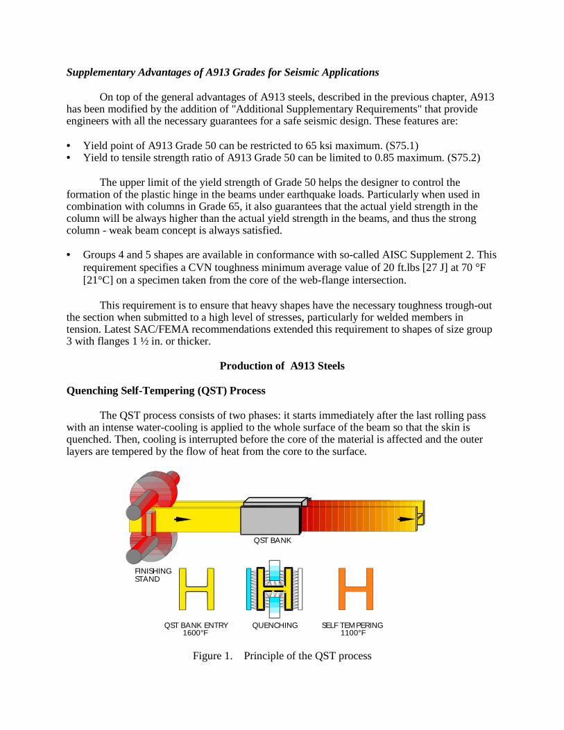
Production of A913 Steels Quenching Self-Tempering (QST) Process
The QST process consists of two phases: it starts immediately after the last rolling pass with an intense water-cooling is applied to the whole surface of the beam so that the skin is quenched. Then, cooling is interrupted before the core of the material is affected and the outer layers are tempered by the flow of heat from the core to the surface.
Figure 1. Principle of the QST process
QST BANK ENTRY QUENCHING SELF TEMPERING1600°F 1100°F
FINISHINGSTAND
QST BANK
Fig. 1 schematically illustrates the QST treatment. At the exit of the finishing stand, directly at the entry of the cooling bank, temperatures are typically 1600 °F [850°C]. After the short cooling phase, the self-tempering temperature is 1100 °F [600°C]. Typical Actual Properties of A913 Steels Toughness
Table 3 shows the statistical distribution of the Charpy V-Notch impact toughness for A913 Grade 50 and Grade 65 at a temperature 70 °F [21°C]. These excellent CVN values based on normal production and without special requirements – such as offshore specifications – show that A913 steels have an outstanding toughness.
Table 3. Charpy V-notch impact energies
CVN test at 70°F [21°C]
A913 Grade 50 ft. lbs [J]
A913 Grade 65 ft. lbs [J]
Average 176 [238] 167 [226] Standard deviation 22 [30] 25 [33] Min. 101 [136] 91 [124] Max. 225 [304] 231 [312]
Weldability
To investigate the claimed “no preheat” feature, the American Welding Institute (AWI 1992) assessed the weldability of “Jumbo” shapes in A913 Grade 65 welded without preheating. This study confirms the outstanding weldability of A913 beams. Lehigh University, Prof. Fisher, (ATLSS 1992) also evaluated the mechanical properties of full section weld splices fabricated from Jumbo sections. The following conclusions demonstrate the excellent material performance: • Heavy A913 Grade 65 beams can be welded successfully using no preheat and according to
AWS D1.1 Structural Welding Code. • Filler metal is commercially available for Shielded Metal Arc Welding (SMAW), Flux-Cored
Arc Welding (FCAW), and Submerged Arc Welding (SAW) for welding A913 Grade 65. • As-welded toughness is substantially better than code requirements. • The weld joint tensile strength exceeds the minimum tensile strength requirements for ASTM
A913 Grade 65 in all the tested joint types (SMAW, FCAW and SAW processes at several heat inputs).
• The toughness of the weld metal in all tested joint types is well in excess of the specification requirements.
• Charpy V-Notch tests performed on base material at the position specified in the AISC requirements for heavy shapes near the web-flange intersection (so-called core location) and at other locations across the flange cross sections show very high levels of fracture toughness well in excess of the specification requirements.
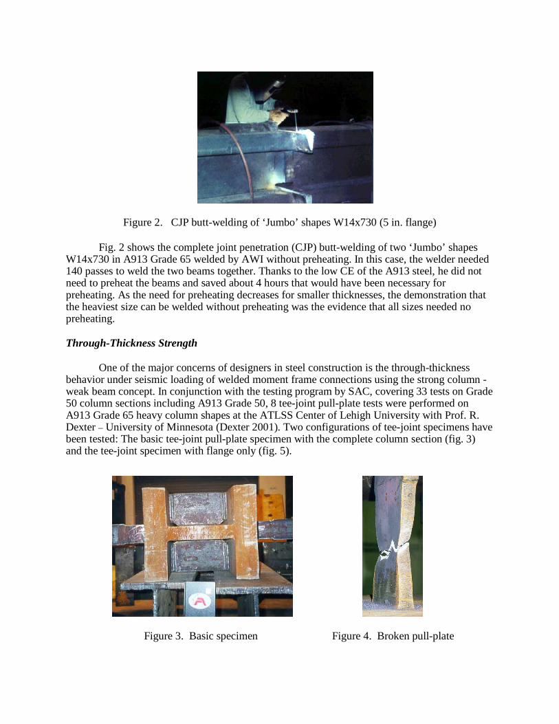
Figure 2. CJP butt-welding of ‘Jumbo’ shapes W14x730 (5 in. flange)
Fig. 2 shows the complete joint penetration (CJP) butt-welding of two ‘Jumbo’ shapes
W14x730 in A913 Grade 65 welded by AWI without preheating. In this case, the welder needed 140 passes to weld the two beams together. Thanks to the low CE of the A913 steel, he did not need to preheat the beams and saved about 4 hours that would have been necessary for preheating. As the need for preheating decreases for smaller thicknesses, the demonstration that the heaviest size can be welded without preheating was the evidence that all sizes needed no preheating.
Through-Thickness Strength
One of the major concerns of designers in steel construction is the through-thickness behavior under seismic loading of welded moment frame connections using the strong column - weak beam concept. In conjunction with the testing program by SAC, covering 33 tests on Grade 50 column sections including A913 Grade 50, 8 tee-joint pull-plate tests were performed on A913 Grade 65 heavy column shapes at the ATLSS Center of Lehigh University with Prof. R. Dexter – University of Minnesota (Dexter 2001). Two configurations of tee-joint specimens have been tested: The basic tee-joint pull-plate specimen with the complete column section (fig. 3) and the tee-joint specimen with flange only (fig. 5).
The specimen types and the results are given in Table 3. The tee-joint specimens were loaded in tension by high yield strength 100 ksi [690MPa] pull-plates. The welds were made at two heat-input levels: 15 and 35 KJ/cm. The higher heat-input level was intended to have the worst possible Heat Affected Zone (HAZ) in the column flange. All specimens broke in either the weld or the pull plates at nominal pull-plate stress levels in excess of 100 ksi [690 MPa], see load-displacement curve in fig. 6.
Figure 5. ‘Flange-only’ specimen, Figure 6. Load-displacement curve with broken pull-plate Fig. 4 shows a typical fracture in the pull-plate after substantial necking. This fracture in the pull plate at higher stresses than the strength of the column flange can be explained by the existence of tri-axial constraint of the column flange material, which creates hydrostatic tension stresses, raising the apparent through-thickness strength. None of these joints failed because of inadequate strength or ductility of the column section. Lamellar tearing did not occur in any of these joints.
Table 3. “Tee-joint” test results on A913 Grade 65 Test
** This weld area (0.003 m2) is measured on a plane 1.6 mm above the column surface, and weld stress is the peak load divided by the weld area.
In summary, through-thickness failure of A913 Grade 65 column sections could not be induced in the tee-joint test, despite applying stress greater than 100 ksi [690 MPa], i.e. well above the strength of any structural steel. Since the through-thickness failure of column sections is very unlikely in moment connections or other types of tee-joints, it is recommended that the through-thickness strength does not need to be explicitly checked in the design of welded beam-to-column connections.
Reduced Beam Section (RBS): The ‘Dog Bone’ Connection
The Luxembourg-based steel manufacturing company, ARBED held a 1989 patent on the RBS. Following the Northridge earthquake, ARBED waived in 1995 all patent and claim rights associated with the RBS for the benefit of the structural design community. This gracious gesture allowed further development of the concept for use in post-Northridge SMF buildings.
Figure 7. Reduced Beam Section (RBS) after testing
The RBS is one type of connection that has been developed to force the plastic hinge away from the beam-column interface. Fig. 7 shows a RBS connection after being tested. This connection relies on the selective removal of beam flange material adjacent to the beam-to-column connection to reduce the cross sectional area of the beam. The flange cut-out can easily be done in the fabrication shop as a constant, tapered or radius cut, the latter turns out to be the most economical today (Moore 1999). Current RBS design procedures assume the minimum specified yield stress of the beam to be 50 ksi or less, and that the minimum specified yield stress of the column is 50 ksi or greater, i.e. Grade 50 or Grade 65 columns. The main advantages of the RBS are: • Smaller moment at column face limits demand, thereby reduces possibility of fracture. • Helps satisfying “strong column - weak beam” requirements. • Minimizes column doubler-plate requirements. • No local undermatching of column when actual properties of beam in Grade 50 are higher
than in the column. • Avoids uneconomical addition of strengthening plates and special welds. • Cost effective, consistently performing connection. • Established performance based on extensive testing.
A913 and the Codes
AISC
Since 1995, A913 Grade 50 and Grade 65 are approved structural steels under the AISC Specifications – ASD and LRFD. AISC Seismic Provisions (AISC 1997), list A913 as ‘Referenced Standard’ – Part I, Chapter 2 – and Grades 50 and 65 are included in ‘Material Specifications’ – Part I, Section 6.1. A913 is included in the LRFD Specification (AISC 1999).
AWS
Since 1995, ASTM A913 is included in the Structural Welding Code AWS D1.1. (AWS 2000) A913 / Grades 50 and 65 are listed as prequalified steels for welding without preheating – at temperatures over 32°F and provided fillers metals with low hydrogen (H8) are used. ICBO – UBC and IBC
In Sept. 1996, ICBO approved A913. UBC (UBC 1997) lists in Chapter 22 Division V, Section. 2213.4, A913 Grades 50 and 65. A913 is also included in IBC 2000 (IBC 2000) – also known as ICC – in Chapter 22 Sect. 2204 by reference to the AISC Specifications. FEMA
FEMA 350 and FEMA 353 (FEMA 2000) Guidelines approve and recommend the use of ASTM A913 Grades 50 and 65 for Special-Moment-Resisting (SMF) applications in order to continue to design with strong column - weak beam concept, cf. FEMA 350: Section 2.6.1 and FEMA 353: Part I, Chapter 2.
Applications
Since 1993, QST-steels in accordance with ASTM A913 have been successfully used in the US and world-wide in numerous projects. One great example for the use of the latest seismic design improvements in steel framing is the 199 Fremont Street building in downtown San Francisco.
Figure 8. ‘Reduced Beam Section’ at 199 Fremont street, SF Courtesy EQE International
“Dog-Bone”
Located in the highest seismic zone 4, this 29-story building encompassing 510’000 sq.-ft. features a dual structural system, which includes a moment-resisting perimeter frame with an eccentrically braced-frame core. The structural frame is configured to maximise the column-free space in the lower stories, through the use of several nine-story-high Vierendeel trusses in the perimeter frame. The steel framed structure was designed with the well-known and established ‘strong column - weak beam’ design concept, using A913 Grade 50 for beams and A913 Grade 65 for columns. Furthermore, the team opted to detail the beam-column connections with reinforced Reduced Beam Section (=RBS), fig. 8, also named “dog-bone solution”, which shifts in the beam the plastic deformation during the event of a shake. These solutions, challenging the demand of the highest earthquake safety, allowed more column-free areas and material cost savings.
Conclusions
A913 Grade 50 and Grade 65 eliminate concerns that engineers may have had about rolled sections used in seismic applications. These steels are easily weldable due to their low carbon equivalent, have an outstanding toughness and excellent ductile behavior. For plastic design purpose, A913 Grade 50 beams can be supplied with limits for maximum yield strength (65 ksi) and max. yield to tensile strength ratio (0.85). Heavy columns in A913 Grade 65 can be supplied with a guaranteed toughness in the web-flange intersection (20 ft.lbs at 70 °F). Thus A913 Grade 50 and Grade 65 are tailored to allow a safe and economic design of special moment resisting frames using the strong column - weak beam concept after the ‘death’ of A36.
References
American Inst. of Steel Constr. (1997). Seismic Provisions for Structural Steel Buildings, Chicago, IL American Inst. of Steel Constr. (1999). LRFD Specification for Structural Steel Buildings, Chicago, IL American Welding Society (2000). Structural Welding Code D1.1, Miami, FL American Welding Institute (1992). Report N° 91-002 ASTM (2001). A913/A913M-00a, ASTM Volume 01.04.Conshohoken, PA ATLSS (1992). Report N ° 92-06. Lehigh University, Bethlehem, PA Dexter R. et al (2001). Engineering Journal 4, Chicago, IL FEMA (2000). Recom. Seismic Design Criteria for New Steel Moment-Frame Buildings, FEMA 350 FEMA (2000). Recom. Spec. and QA Guidelines for SMF Constr. for Seismic Appl., FEMA 353 IBC (2000). International Building Code Moore K.S., Malley J.O., Engelhardt M.D. (1999). Steel Tips-Design of Reduced Beam Section Moment
Frame Connections, Structural Steel Educational Council UBC (1997). Uniform Building Code