STEERING TABLE OF CONTENTS page page POWER STEERING ......................... 1 POWER STEERING PUMP ................... 6 POWER STEERING GEAR ................... 11 STEERING LINKAGE ....................... 22 STEERING COLUMN ....................... 26 POWER STEERING TABLE OF CONTENTS page page DESCRIPTION AND OPERATION POWER STEERING SYSTEM ................ 1 DIAGNOSIS AND TESTING POWER STEERING SYSTEM DIAGNOSIS CHARTS ............................... 2 STEERING FLOW AND PRESSURE............ 4 DESCRIPTION AND OPERATION POWER STEERING SYSTEM DESCRIPTION The power steering pump (Fig. 1) is a constant flow rate and displacement vane type pump. The pump reservoir is attached to the pump body. The pump is connected to the steering by the pressure and return hoses. The steering gear (Fig. 1) used is a recirculating ball type gear. A tilt and non-tilt column provide steering input. The power steering system consists of: • Hydraulic pump • Recirculating ball steering gear • Steering column • Steering linkage • Cooler (optional) OPERATION The rack piston balls act as a rolling thread between the worm shaft and rack piston. The worm shaft is sup- ported by a thrust bearing at the lower end and a bear- ing assembly at the upper end. When the worm shaft is turned from input from the steering column the rack piston moves. The rack piston teeth mesh with the pit- man shaft. Turning the worm shaft turns the pitman shaft, which moves the steering linkage. Fig. 1 Power Steering Gear & Pump 1 – STEERING GEAR 2 – PRESSURE HOSE 3 – PUMP 4 – RETURN HOSE 5 – RESERVOIR WJ STEERING 19 - 1
ESCRIPTIONThe power steering pump (Fig. 1) is a constant
low rate and displacement vane type pump. Theump reservoir is attached to the pump body. Theump is connected to the steering by the pressurend return hoses. The steering gear (Fig. 1) used is aecirculating ball type gear. A tilt and non-tilt columnrovide steering input.The power steering system consists of:• Hydraulic pump• Recirculating ball steering gear• Steering column• Steering linkage• Cooler (optional)
PERATIONThe rack piston balls act as a rolling thread between
he worm shaft and rack piston. The worm shaft is sup-orted by a thrust bearing at the lower end and a bear-ng assembly at the upper end. When the worm shaft isurned from input from the steering column the rackiston moves. The rack piston teeth mesh with the pit-an shaft. Turning the worm shaft turns the pitman
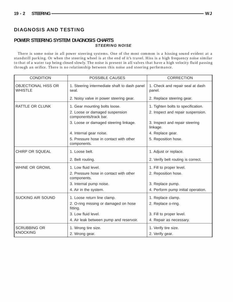
OWER STEERING SYSTEM DIAGNOSIS CHARTSSTEERING NOISE
There is some noise in all power steering systems. One of the most common is a hissing sound evident at atandstill parking. Or when the steering wheel is at the end of it’s travel. Hiss is a high frequency noise similaro that of a water tap being closed slowly. The noise is present in all valves that have a high velocity fluid passinghrough an orifice. There is no relationship between this noise and steering performance.
CONDITION POSSIBLE CAUSES CORRECTION
OBJECTIONAL HISS ORWHISTLE
1. Steering intermediate shaft to dash panelseal.
1. Check and repair seal at dashpanel.
2. Noisy valve in power steering gear. 2. Replace steering gear.
RATTLE OR CLUNK 1. Gear mounting bolts loose. 1. Tighten bolts to specification.
2. Loose or damaged suspensioncomponents/track bar.
2. Inspect and repair suspension.
3. Loose or damaged steering linkage. 3. Inspect and repair steeringlinkage.
4. Internal gear noise. 4. Replace gear.
5. Pressure hose in contact with othercomponents.
5. Reposition hose.
CHIRP OR SQUEAL 1. Loose belt. 1. Adjust or replace.
2. Belt routing. 2. Verify belt routing is correct.
WHINE OR GROWL 1. Low fluid level. 1. Fill to proper level.
2. Pressure hose in contact with othercomponents.
2. Reposition hose.
3. Internal pump noise. 3. Replace pump.
4. Air in the system. 4. Perform pump initial operation.
SUCKING AIR SOUND 1. Loose return line clamp. 1. Replace clamp.
2. O-ring missing or damaged on hosefitting.
2. Replace o-ring.
3. Low fluid level. 3. Fill to proper level.
4. Air leak between pump and reservoir. 4. Repair as necessary.
SCRUBBING ORKNOCKING
1. Wrong tire size. 1. Verify tire size.
2. Wrong gear. 2. Verify gear.
Sc
WJ STEERING 19 - 3
DIAGNOSIS AND TESTING (Continued)
BINDING AND STICKING
CONDITION POSSIBLE CAUSE CORRECTION
DIFFICULT TO TURN WHEELSTICKS OR BINDS
1. Low fluid level. 1. Fill to proper level.
2. Tire pressure. 2. Adjust tire pressure.
3. Steering component. 3. Inspect and lube.
4. Loose belt. 4. Adjust or replace.
5. Low pump pressure. 5. Pressure test and replace ifnecessary.
4. Gear out of adjustment. 4. Adjust gear to specification.
5. Worn or loose steering coupler. 5. Repair as necessary.
VEHICLE PULLS TO ONE SIDEDURING BRAKING
1. Tire Pressure. 1. Adjust tire pressure.
2. Air in brake hydrauliics system. 2. Bleed brake system.
3. Worn brake components. 3. Repair as necessary.
VEHICLE LEADS OR DRIFTSFROM STRAIGHT AHEADDIRECTION ON UNCROWNEDROAD.
1. Tire pressure. 1. Adjust tire pressure.
2. Radial tire lead. 2. Cross front tires.
3. Brakes dragging. 3. Repair as necessary.
4. Wheel alignment. 4. Align vehicle.
5. Weak or broken spring. 5. Replace spring.
6. Loose or worn steering/suspension components.
6. Repair as necessary.
7. Cross caster out of spec. 7. Adjust or replace axle asnecessary.
TEERING FLOW AND PRESSUREThe following procedure is used to test the opera-
ion of the power steering system on the vehicle. Thisest will provide the gallons per minute (GPM) orlow rate of the power steering pump along with theaximum relief pressure. Perform test any time a
ower steering system problem is present. This testill determine if the power steering pump or power
teering gear is not functioning properly. The follow-ng pressure and flow test is performed using Powerteering Analyzer Tool kit 6815 (Fig. 2) and Adapterit 6893.
LOW AND PRESSURE TEST(1) Check the power steering belt to ensure it is in
ood condition and adjusted properly.(2) Connect pressure gauge hose from the Power
teering Analyzer to Tube 6865.(3) Connect Adapter 6826 to Power Steering Ana-
yzer test valve end.(4) Disconnect the high pressure hose from the
ower steering pump.(5) Connect Tube 6865 to the pump hose fitting.(6) Connect the power steering hose from the
teering gear to Adapter 6826.(7) Open the test valve completely.
(8) Start engine and let idle long enough to circu-late power steering fluid through flow/pressure testgauge.
(9) Shut off the engine and check the fluid level,dd fluid as necessary. Start engine again and letdle.
(10) The initial pressure reading should be45-552 kPa (50-80 psi). If pressure is higher inspecthe hoses for restrictions and repair as necessary.
(11) Increase the engine speed to 1500 RPM andead the flow meter. The reading should be 2.4 - 2.8PM, if the reading is below this specification theump should be replaced.
AUTION: This next step involves testing maxi-um pump pressure output and flow control valveperation. Do not leave valve closed for more than
hree seconds as the pump could be damaged.
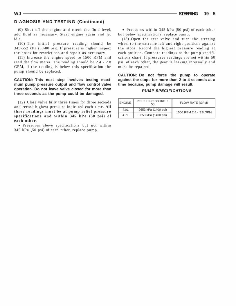
(12) Close valve fully three times for three secondsnd record highest pressure indicated each time. Allhree readings must be at pump relief pressurepecifications and within 345 kPa (50 psi) ofach other.• Pressures above specifications but not within
45 kPa (50 psi) of each other, replace pump.
• Pressures within 345 kPa (50 psi) of each otherbut below specifications, replace pump.
(13) Open the test valve and turn the steeringwheel to the extreme left and right positions againstthe stops. Record the highest pressure reading ateach position. Compare readings to the pump specifi-cations chart. If pressures readings are not within 50psi. of each other, the gear is leaking internally andmust be repaired.
CAUTION: Do not force the pump to operateagainst the stops for more than 2 to 4 seconds at atime because, pump damage will result.
ESCRIPTIONHydraulic pressure for the power steering system
s provided by a belt driven power steering pumpFig. 1). The pump shaft has a pressed-on drive pul-ey that is belt driven by the crankshaft pulley.
PERATIONThe power steering pump is a constant flow rate
nd displacement, vane-type pump. The pump inter-al parts operate submerged in fluid. The flow con-rol orifice is part of the high pressure line fitting.he pressure relief valve inside the flow control valve
imits the pump pressure. The reservoir is attachedo the pump body with spring clips. The power steer-ng pump is connected to the steering gear by theressure and return hoses.
OTE: Power steering pumps have different pres-ure rates and are not interchangeable with otherumps.
OWER STEERING PRESSURE LINE
ESCRIPTIONThe hose consists of two metal ends and rubber
enter section that contains a tuning cable. Theump end uses a quick connect fitting.
PERATIONPower steering pressure line, is used to transfer
igh pressure power steering fluid, from the powerteering pump to the power steering gear.
POWER STEERING RETURN LINE
DESCRIPTIONPower steering return line is a hose which is
PERATIONPower steering return line, is used to transfer low
ressure power steering fluid, from the power steer-ng gear to the power steering pump.
IAGNOSIS AND TESTING
UMP LEAKAGE DIAGNOSIS
ERVICE PROCEDURES
OWER STEERING PUMP - INITIALPERATION
ARNING: THE FLUID LEVEL SHOULD BEHECKED WITH ENGINE OFF TO PREVENT INJURYROM MOVING COMPONENTS.
AUTION: Use MOPAR Power Steering Fluid orquivalent. Do not use automatic transmission fluidnd do not overfill.
Wipe filler cap clean, then check the fluid level.he dipstick should indicate COLD when the fluid ist normal ambient temperature.(1) Fill the pump fluid reservoir to the proper level
nd let the fluid settle for at least two minutes.(2) Start the engine and let run for a few seconds
hen turn engine off.
(3) Add fluid if necessary. Repeat the above proce-dure until the fluid level remains constant after run-ning the engine.
(4) Raise the front wheels off the ground.(5) Slowly turn the steering wheel right and left,
lightly contacting the wheel stops at least 20 times.(6) Check the fluid level add if necessary.(7) Lower the vehicle, start the engine and turn
the steering wheel slowly from lock to lock.(8) Stop the engine and check the fluid level and
refill as required.(9) If the fluid is extremely foamy or milky look-
ing, allow the vehicle to stand a few minutes andrepeat the procedure.
CAUTION: Do not run a vehicle with foamy fluid foran extended period. This may cause pump damage.
REMOVAL AND INSTALLATION
POWER STEERING PUMP – 4.0L
REMOVAL(1) Remove serpentine drive belt, refer to Group 7
Cooling.(2) Remove pressure and return hoses from pump
and drain the pump.(3) Loosen the pump bracket bolt at the engine
block.(4) Remove 3 pump mounting bolts (Fig. 2)
through pulley access holes.(5) Tilt pump downward and remove from engine.(6) Remove pulley from pump.
INSTALLATION(1) Install pulley on pump.(2) Install pump on the engine mounting bracket.(3) Install 3 pump mounting bolts and tighten to
27 N·m (20 ft. lbs.).(4) Tighten pump bracket bolt to 57 N·m (42 ft.
lbs.).(5) Install the pressure line on the pump and
tighten to 28 N·m (21 ft. lbs.).(6) Install return hoses on pump.(7) Install drive belt, refer to Group 7 Cooling.(8) Add power steering fluid, refer to Power Steer-
ing Pump Initial Operation.
POWER STEERING PUMP - 4.7L
REMOVAL(1) Remove the serpentine drive belt. Refer to
Group 7 Cooling.(2) Remove the pressure and return hoses from
pump and drain pump.
a
cb
19 - 8 STEERING WJ
REMOVAL AND INSTALLATION (Continued)
(3) Remove 3 pump mounting bolts through pulleyccess holes (Fig. 3).(4) Remove the pump from the vehicle.
Fig. 3 Pump Mounting1 – LEFT CYLINDER HEAD2 – PUMP
INSTALLATION(1) Position the pump on the left cylinder head
and install bolts through pulley access holes. Tightenbolts to 40 N·m (30 ft. lbs.).
(2) Install the pressure and return hoses to pump.(3) Install serpentine drive belt, refer to Group 7
Cooling.(4) Add power steering fluid. Refer to Power Steer-
ing Pump Initial Operation in this section.
DISASSEMBLY AND ASSEMBLY
PUMP PULLEY
DISASSEMBLY(1) Remove pump assembly.(2) Remove pulley from pump with Puller C-4333
or equivalent puller (Fig. 4).
ASSEMBLY
NOTE: The pulley is marked front for installation.
(1) Replace pulley if bent, cracked, or loose.(2) Install pulley on pump with Installer C-4063-B
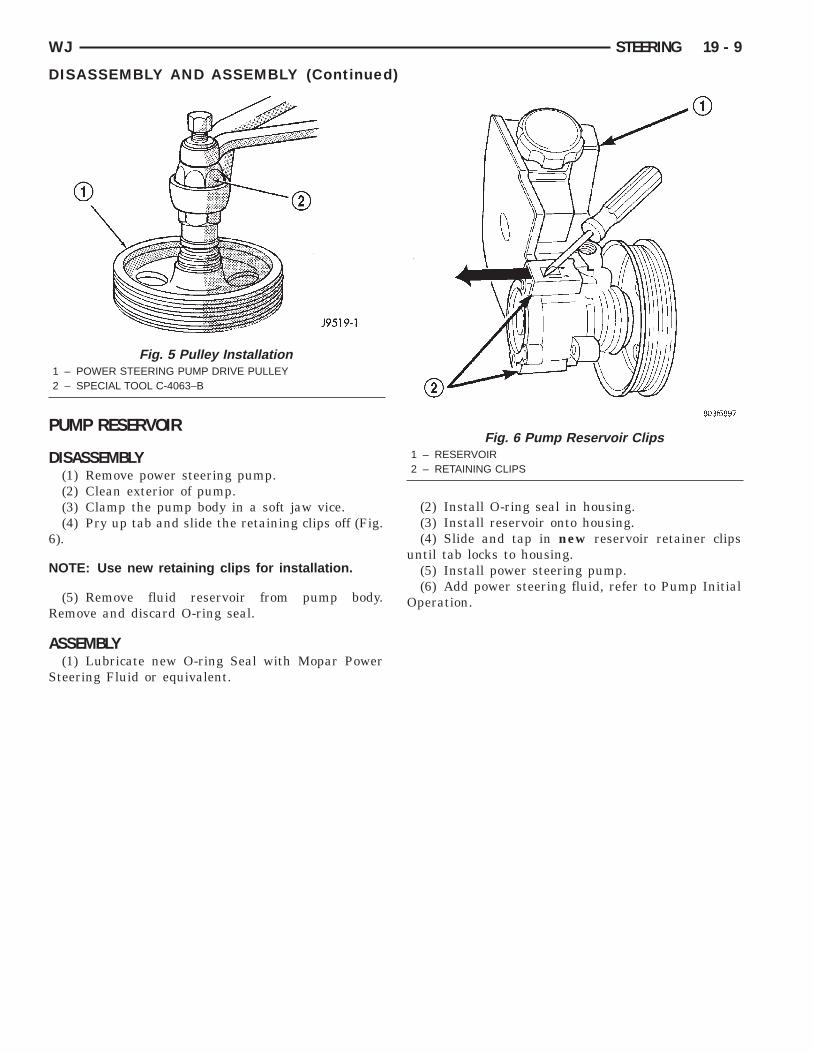
or equivalent installer (Fig. 5). The front edge of thepulley hub must be flush with the end of the shaft.Ensure the tool and pulley are aligned with thepump shaft.
(3) Install pump assembly.(4) With Serpentine Belt, run engine until warm (5
min.) and note any belt chirp. If chirp exists, movepulley outward approximately 0.5 mm (0.020 in.). Ifnoise increases, press on 1.0 mm (0.040 in.). Beareful that pulley does not contact mountingolts.
Fig. 4 Pulley Removal1 – POWER STEERING PUMP DRIVE PULLEY2 – SPECIAL TOOL C-4333
P
D
6
N
R
A
S
WJ STEERING 19 - 9
DISASSEMBLY AND ASSEMBLY (Continued)
UMP RESERVOIR
ISASSEMBLY(1) Remove power steering pump.(2) Clean exterior of pump.(3) Clamp the pump body in a soft jaw vice.(4) Pry up tab and slide the retaining clips off (Fig.
).
OTE: Use new retaining clips for installation.
(5) Remove fluid reservoir from pump body.emove and discard O-ring seal.
SSEMBLY(1) Lubricate new O-ring Seal with Mopar Power
Fig. 5 Pulley Installation1 – POWER STEERING PUMP DRIVE PULLEY2 – SPECIAL TOOL C-4063–B
teering Fluid or equivalent.
(2) Install O-ring seal in housing.(3) Install reservoir onto housing.(4) Slide and tap in new reservoir retainer clips
until tab locks to housing.(5) Install power steering pump.(6) Add power steering fluid, refer to Pump Initial
ESCRIPTIONThe power steering gear is a recirculating ball type
ear (Fig. 1).The following gear components can be serviced:• Pitman Shaft and Cover• Pitman Shaft Bearings• Pitman Shaft Oil Seal/Dust Seal• Stud Shaft Housing with Seal
NOTE: If rack piston assembly is damaged the gearmust be replaced.
OPERATIONThe gear acts as a rolling thread between the
worm shaft and rack piston. The worm shaft is sup-ported by a thrust bearing at the lower end and abearing assembly at the upper end. When the wormshaft is turned the rack piston moves. The rack pis-ton teeth mesh with the pitman shaft. Turning theworm shaft turns the pitman shaft, which turns thesteering linkage.
SSEMBLY(1) Grease stub shaft seal with special grease
upplied with new stub shaft housing.(2) Install new stub shaft housing o-rings.(3) Install housing on the steering gear.(4) Install the housing bolts and tighten to 62 N·m46 ft. lbs.).
ITMAN SHAFT/SEALS/BEARINGS
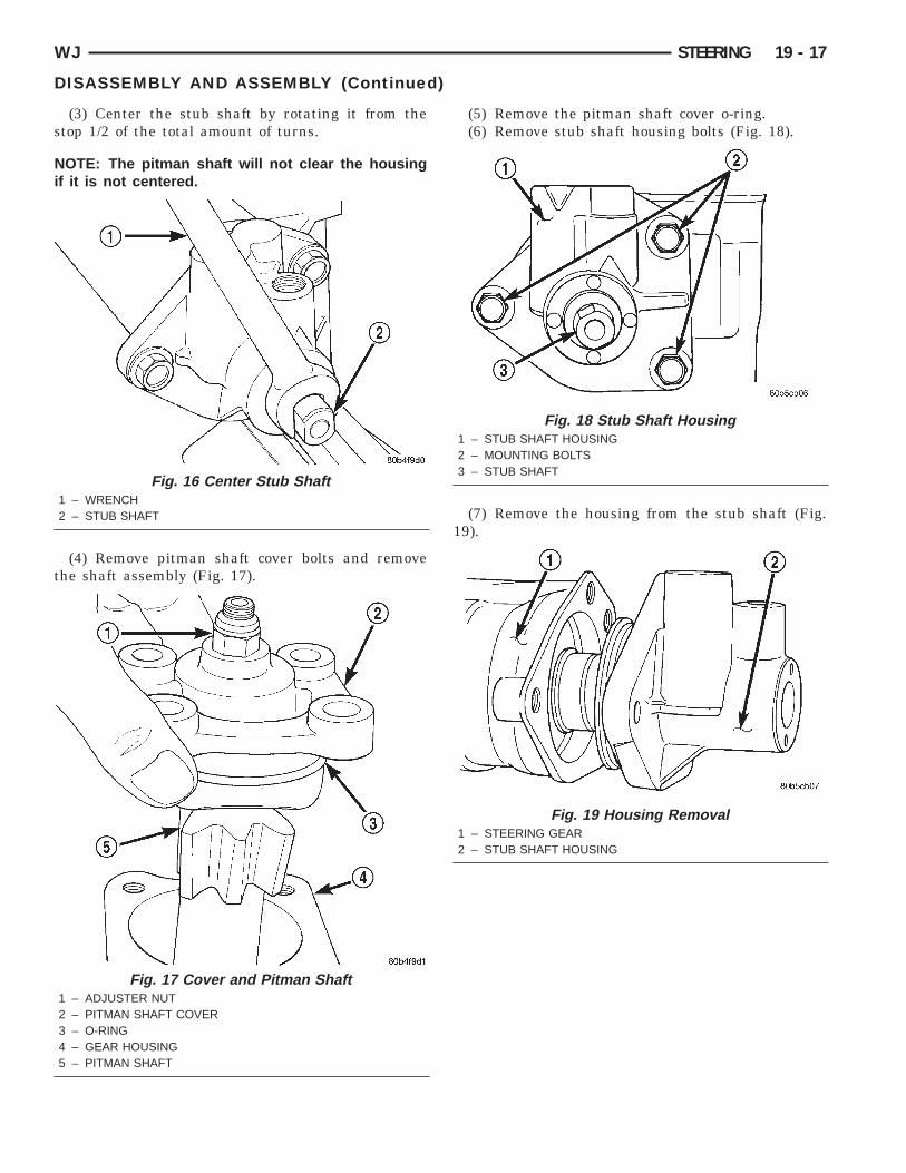
ISASSEMBLY(1) Clean exposed end of pitman shaft and housingith a wire brush.(2) Rotate the stub shaft with a wrench (Fig. 7)
rom stop to stop and count the number of turns.(3) Center the stub shaft by rotating it from the
top 1/2 of the total amount of turns.
OTE: The pitman shaft will not clear the housingf it is not centered.
Fig. 9 Dust Seal Removal1 – PULLER2 – STEERING GEAR
Fig. 10 Oil Seal Retaining Ring1 – SNAP RING PLIERS2 – RETAINING RING
Fig. 11 Backup Washers1 – METAL BACK UP WASHER2 – PLASTIC BACK UP WASHER
Fig. 12 Oil Seal Removal1 – PULLER2 – STEERING GEAR
aIl
b
A
8h
Np
19 - 16 STEERING WJ
DISASSEMBLY AND ASSEMBLY (Continued)
(10) Drop Driver 8277 through the top bearing andlign the driver up with the lower bearing. (Fig. 13).nstall Handle C-4171 into the driver and remove theower bearing.
(11) Turn the gear over and remover the upperearing with Driver 8277 and Handle C-4171.
SSEMBLY(1) Install upper pitman shaft bearing, with Driver
294 and Handle C-4171 (Fig. 14). Drive bearing intoousing until the driver bottoms out.
OTE: Install upper pitman shaft bearing with theart number/letters facing the driver.
(2) Install lower pitman shaft bearing with theother side Driver 8294 and Handle C-4171 (Fig. 15).Drive bearing into housing until the bearing shoulderis seated against the housing.
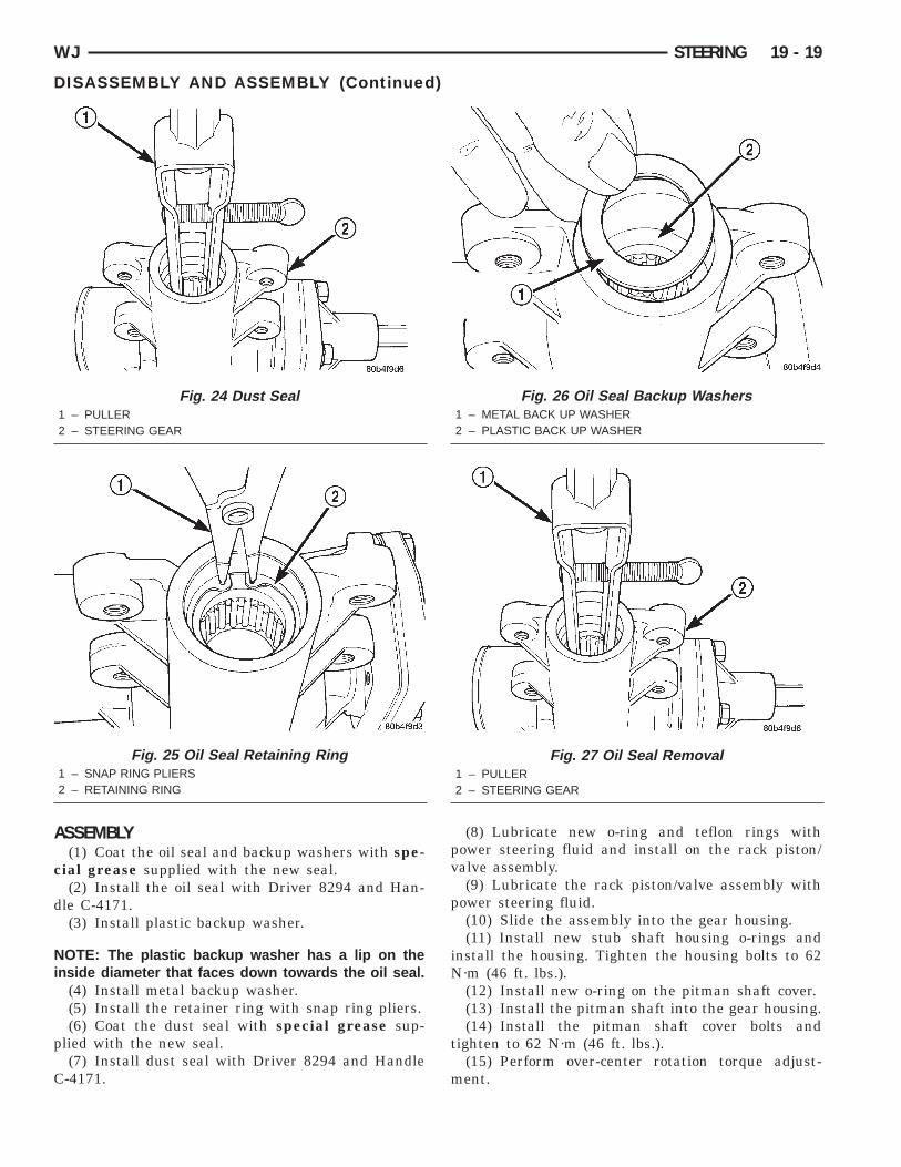
(3) Coat the oil seal and backup washers with spe-cial grease supplied with the new seal.
(4) Install the oil seal with Driver 8294 and Han-dle C-4171.
(5) Install plastic backup washer.
NOTE: The plastic backup washer has a lip on theinside diameter that faces down towards the oilseal.
(6) Install metal backup washer.(7) Install the retainer ring with snap ring pliers.(8) Coat the dust seal with special grease sup-
plied with the new seal.(9) Install dust seal with Driver 8294 and Handle
C-4171.(10) Install new pitman shaft cover o-ring.(11) Install pitman shaft assembly into the hous-
ing.(12) Install cover bolts and tighten to 62 N·m (46
ft. lbs.).(13) Perform over-center rotation torque adjustment.
RACK PISTON/VALVE ASSEMBLY
DISASSEMBLY(1) Clean exposed end of pitman shaft and housing
with a wire brush.(2) Rotate the stub shaft with a wrench (Fig. 16)
Fig. 23 Teflon Rings And O-Ring1 – RACK PISTON2 – VALVE3 – TEFLON RINGS4 – TEFLON AND O-RING
A
c
d
Ni
p
C
WJ STEERING 19 - 19
DISASSEMBLY AND ASSEMBLY (Continued)
SSEMBLY(1) Coat the oil seal and backup washers with spe-
ial grease supplied with the new seal.(2) Install the oil seal with Driver 8294 and Han-
le C-4171.(3) Install plastic backup washer.
OTE: The plastic backup washer has a lip on thenside diameter that faces down towards the oil seal.
(4) Install metal backup washer.(5) Install the retainer ring with snap ring pliers.(6) Coat the dust seal with special grease sup-
lied with the new seal.(7) Install dust seal with Driver 8294 and Handle-4171.
Fig. 24 Dust Seal1 – PULLER2 – STEERING GEAR
Fig. 25 Oil Seal Retaining Ring1 – SNAP RING PLIERS2 – RETAINING RING
(8) Lubricate new o-ring and teflon rings withpower steering fluid and install on the rack piston/valve assembly.
(9) Lubricate the rack piston/valve assembly withpower steering fluid.
(10) Slide the assembly into the gear housing.(11) Install new stub shaft housing o-rings and
install the housing. Tighten the housing bolts to 62N·m (46 ft. lbs.).
(12) Install new o-ring on the pitman shaft cover.(13) Install the pitman shaft into the gear housing.(14) Install the pitman shaft cover bolts and
tighten to 62 N·m (46 ft. lbs.).(15) Perform over-center rotation torque adjust-
ment.
Fig. 26 Oil Seal Backup Washers1 – METAL BACK UP WASHER2 – PLASTIC BACK UP WASHER
Fig. 27 Oil Seal Removal1 – PULLER2 – STEERING GEAR
A
S
Nnap
O
s
s
tdet
Ns
tlrr
0R
Tn(t
nsi
Nt
tl
19 - 20 STEERING WJ
DJUSTMENTS
TEERING GEAR
OTE: Adjusting the steering gear in the vehicle isot recommended. Remove gear from the vehiclend drain the fluid. Then mount gear in a vise toerform adjustments.
VER-CENTER(1) Rotate the stub shaft with Socket 8343 from
top to stop and count the number of turns.(2) Center the stub shaft by rotating it from the
top 1/2 of the total amount of turns.(3) Place torque wrench and Socket 8343 in a ver-
ical position on the stub shaft. Rotate the wrench 45egrees each side of the center and record the high-st rotational torque in this range (Fig. 28). This ishe Over-Center Rotating Torque.
OTE: The stub shaft must rotate smoothly withoutticking or binding.
(4) Rotate the stub shaft between 90° and 180° tohe left of center and record the left off-center pre-oad. Repeat this to the right of center and record theight off-center preload. The average of these twoecorded readings is the Preload Rotating Torque.(5) The Over-Center Rotating Torque should be
.45-0.80 N·m (4-7 in. lbs.) higher than the Preloadotating Torque.(6) If an adjustment to the Over-Center Rotating
orque is necessary, first loosen the adjuster lockut. Then turn the pitman shaft adjuster screw backCOUNTERCLOCKWISE) until fully extended, thenurn back in (CLOCKWISE) one full turn.
(7) Remeasure Over-Center Rotating Torque. Ifecessary turn the adjuster screw and repeat mea-urement until correct Over-Center Rotating Torques reached.
OTE: To increase the Over-Center Rotating Torqueurn the screw CLOCKWISE.
(8) Prevent the adjuster screw from turning whileightening adjuster lock nut. Tighten the adjusterock nut to 37-52 N·m (27-38 ft. lbs.).
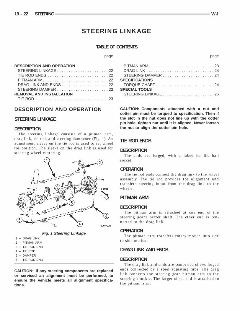
ESCRIPTIONThe steering linkage consists of a pitman arm,
rag link, tie rod, and steering dampener (Fig. 1). Andjustment sleeve on the tie rod is used to set wheeloe position. The sleeve on the drag link is used forteering wheel centering.
AUTION: If any steering components are replacedr serviced an alignment must be performed, tonsure the vehicle meets all alignment specifica-
ions.
Fig. 1 Steering Linkage1 – DRAG LINK2 – PITMAN ARM3 – TIE ROD END4 – TIE ROD5 – DAMPER6 – TIE ROD END
CAUTION: Components attached with a nut andcotter pin must be torqued to specification. Then ifthe slot in the nut does not line up with the cotterpin hole, tighten nut until it is aligned. Never loosenthe nut to align the cotter pin hole.
TIE ROD ENDS
DESCRIPTIONThe ends are forged, with a lubed for life ball
socket.
OPERATIONThe tie rod ends connect the drag link to the wheel
assembly. The tie rod provides toe alignment andtransfers steering input from the drag link to thewheels.
PITMAN ARM
DESCRIPTIONThe pitman arm is attached at one end of the
steering gear’s sector shaft. The other end is con-nected to the drag link.
OPERATIONThe pitman arm transfers rotary motion into side
to side motion.
DRAG LINK AND ENDS
DESCRIPTIONThe drag link and ends are comprised of two forged
ends connected by a steel adjusting tube. The draglink connects the steering gear pitman arm to thesteering knuckle. The larger offset end is attached tothe pitman arm.
O
S
D
ts
O
d
R
T
R
(
r
k
u
WJ STEERING 19 - 23
DESCRIPTION AND OPERATION (Continued)
PERATIONThe sleeve is used for steering wheel centering.
TEERING DAMPER
ESCRIPTIONThe damper is mounted to the axle housing and
he tie rod end. The damper consists of steel tubehock absorber with a permanent bushed end.
PERATIONThe steering damper provides steering system
amping.
EMOVAL AND INSTALLATION
IE ROD
EMOVAL(1) Raise and support the vehicle.(2) Remove wheel and tire assemblies.(3) Remove the damper nut from the tie rod clamp
Fig. 2).(4) Remove the damper from the tie rod.(5) Remove the cotter pins and nuts from the tie
od ends at the steering knuckles (Fig. 2).(6) Remove the tie rod ends from the steering
nuckles with Puller C-3894-A..(7) Loosen the adjustment sleeve clamp bolts and
nscrew the tie rod ends from the sleeve.
Fig. 2 Tie Rod Assembly1 – TIE ROD END2 – CLAMP3 – DAMPER4 – TIE ROD5 – CLAMP6 – TIE ROD END
INSTALLATION(1) Screw the tie rod ends into the adjustment
sleeve.(2) Install the tie rod on the steering knuckles and
install the nuts.(3) Tighten the nuts to 47 N·m (35 ft. lbs.). Install
new cotter pins and bend end 60°.(4) Position the adjustment sleeve clamp bolts to
their original location and tighten to 41 N·m (30 ft.lbs.).
(5) Install the damper on the tie rod and installthe nut.
(6) Tighten the nut to 41 N·m (30 ft. lbs.). Installnew cotter pins and bend end 60°.
(7) Install wheel and tire assemblies.(8) Remove support and lower the vehicle.(9) Perform toe position adjustment.
PITMAN ARM
REMOVAL(1) Remove the cotter pin and nut from the drag
link at the pitman arm (Fig. 3).(2) Remove the drag link ball stud from the pit-
man arm with a puller.(3) Remove the nut and washer from the steering
gear shaft. Mark the pitman shaft and pitman armfor installation reference. Remove the pitman armfrom steering gear with Puller C-4150A.
INSTALLATION(1) Align and install the pitman arm on steering
gear shaft.(2) Install the washer and nut on the shaft and
tighten the nut to 251 N·m (185 ft. lbs.).
Fig. 3 Pitman Arm1 – STEERING GEAR2 – PITMAN ARM
Ia
D
R
s
k
u
I
s
k
N(
a
19 - 24 STEERING WJ
REMOVAL AND INSTALLATION (Continued)
(3) Install drag link ball stud to pitman arm.nstall nut and tighten to 88 N·m (65 ft. lbs.). Install
new cotter pin.
RAG LINK
EMOVAL(1) Raise and support the vehicle.(2) Remove right wheel and tire assembly.(3) Remove the cotter pins and nuts at the right
teering knuckle and pitman arm (Fig. 4).(4) Remove the drag link from the steering
nuckle and pitman arm Puller C-3894-A.(5) Loosen adjustment sleeve clamp bolts and
nscrew the tie rod ends from the adjustment sleeve.
NSTALLATION(1) Screw the tie rod ends into the adjustment
leeve.(2) Install the drag link onto the right steering
nuckle and pitman arm.(3) Tighten the nut at the steering knuckle to 47·m (35 ft. lbs.). Tighten the pitman nut to 88 N·m
65 ft. lbs.). Install new cotter pins.(4) Position clamp bolts to their original position
nd tighten to 41 N·m (30 ft. lbs.).(5) Install right wheel and tire assembly.(6) Remove support and lower the vehicle.(7) Center the steering wheel.
ESCRIPTIONThe tilt column (Fig. 1) has been designed to be
erviced as an assembly, less the wiring, switches,hrouds, steering wheel, etc. Most steering columnomponents can be serviced without removing theteering column from the vehicle.
ERVICE WARNINGS AND CAUTIONSTo service the steering wheel, switches or airbag,
efer to Group 8M and follow all WARNINGS andAUTIONS.
ARNING: THE AIRBAG SYSTEM IS A SENSITIVE,OMPLEX ELECTRO-MECHANICAL UNIT. BEFORETTEMPTING TO DIAGNOSE, REMOVE OR INSTALLHE AIRBAG SYSTEM COMPONENTS YOU MUSTIRST DISCONNECT AND ISOLATE THE BATTERYEGATIVE (GROUND) CABLE. THEN WAIT TWOINUTES FOR THE SYSTEM CAPACITOR TO DIS-HARGE. FAILURE TO DO SO COULD RESULT INCCIDENTAL DEPLOYMENT OF THE AIRBAG ANDOSSIBLE PERSONAL INJURY. THE FASTENERS,CREWS, AND BOLTS, ORIGINALLY USED FOR
Fig. 1 Steering Column
THE AIRBAG COMPONENTS, HAVE SPECIAL COAT-INGS AND ARE SPECIFICALLY DESIGNED FOR THEAIRBAG SYSTEM. THEY MUST NEVER BEREPLACED WITH ANY SUBSTITUTES. ANYTIME ANEW FASTENER IS NEEDED, REPLACE WITH THECORRECT FASTENERS PROVIDED IN THE SERVICEPACKAGE OR FASTENERS LISTED IN THE PARTSBOOKS.
CAUTION: Safety goggles should be worn at alltimes when working on steering columns.
REMOVAL AND INSTALLATION
STEERING COLUMN
WARNING: BEFORE SERVICING THE STEERINGCOLUMN THE AIRBAG SYSTEM MUST BE DIS-ARMED. FAILURE TO DO SO MAY RESULT IN ACCI-DENTAL DEPLOYMENT OF THE AIRBAG ANDPOSSIBLE PERSONAL INJURY. REFER TO GROUP8M RESTRAINT SYSTEMS FOR SERVICE PROCE-DURES.
REMOVAL(1) Position front wheels straight ahead.(2) Disconnect and isolate the negative (ground)
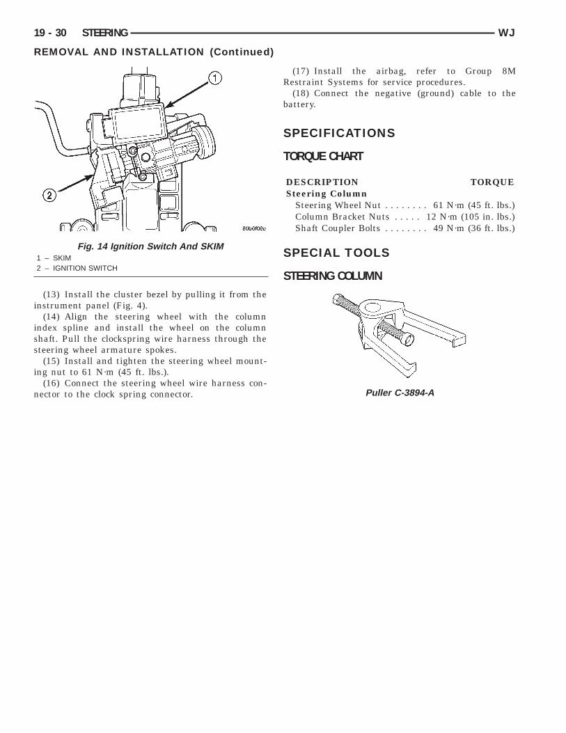
cable from the battery.(3) Remove the airbag, refer to Group 8M
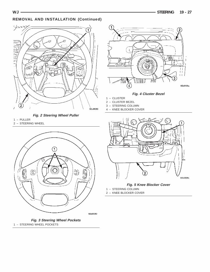
Restraint Systems for service procedures.(4) Remove the steering wheel nut and remove
wheel with Puller C-3894-A (Fig. 2).
NOTE: Ensure the puller jaws are seated in thepockets (Fig. 3) of the steering wheel armature.
(5) Remove the cluster bezel by pulling it from theinstrument panel (Fig. 4).
(6) Remove the knee blocker cover (Fig. 5), refer toGroup 8E Instrument Panel Systems.
(8) Unsnap the two halves of the column shroudsy pressing on the sides of the upper shroud and tilt-ng the rear of the upper shroud up. Remove thehrouds from the steering column (Fig. 7).
(9) Remove the upper fixed shroud mountingcrews and remove the shroud (Fig. 8).(10) Disconnect the multifuction switch (Fig. 9)
nd ignition switch harness.(11) Remove the multifuction switch screw from
nderneath the switch (Fig. 10). Slide the multifuc-
(13) Install the cluster bezel by pulling it from thenstrument panel (Fig. 4).
(14) Align the steering wheel with the columnndex spline and install the wheel on the columnhaft. Pull the clockspring wire harness through theteering wheel armature spokes.(15) Install and tighten the steering wheel mount-
ng nut to 61 N·m (45 ft. lbs.).(16) Connect the steering wheel wire harness con-