18
Steering Servo How to control the car heading via a steering servo Team: //noComment Leader : Christian Software Specialist : Matt Hardware Specialist : Vic Assistant : Andrew
| Date post: | 17-Dec-2015 |
| Category: |
Documents |
| Upload: | homer-stewart |
| View: | 216 times |
| Download: | 0 times |

Steering Servo How to control the car heading via a steering servo
Team: //noComment
Leader : Christian
Software Specialist : Matt
Hardware Specialist : Vic
Assistant : Andrew

Overview Hardware
Futaba S3010 Specs Components Needed Wiring
Interfacing
Registers Used Register Diagram
Analog to Digital Conversion PWM Review
Mechanical Binding Test Software Implementation Summary References Questions
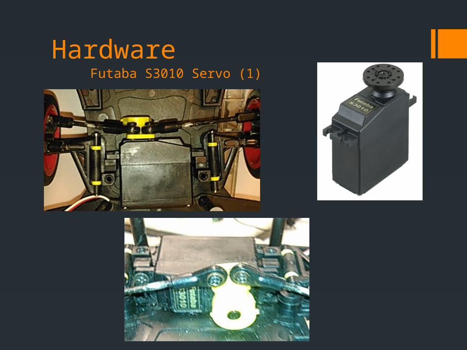
HardwareFutaba S3010 Servo (1)
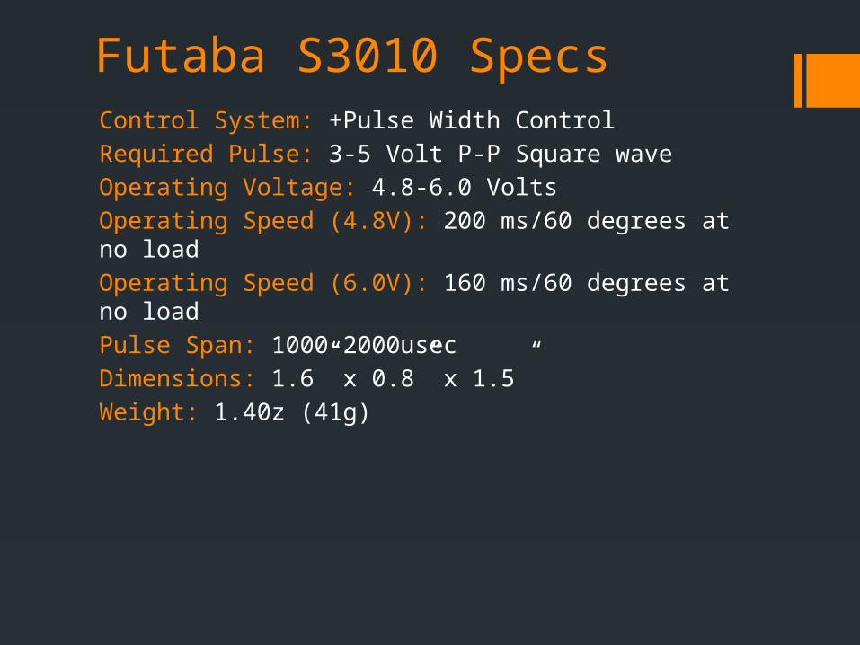
Futaba S3010 SpecsControl System: +Pulse Width Control
Required Pulse: 3-5 Volt P-P Square wave
Operating Voltage: 4.8-6.0 Volts
Operating Speed (4.8V): 200 ms/60 degrees at no load
Operating Speed (6.0V): 160 ms/60 degrees at no load
Pulse Span: 1000-2000usec
Dimensions: 1.6” x 0.8” x 1.5”
Weight: 1.40z (41g)
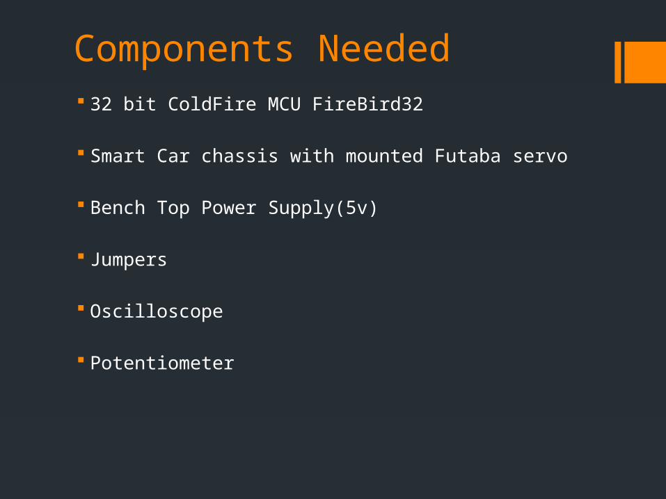
Components Needed 32 bit ColdFire MCU FireBird32
Smart Car chassis with mounted Futaba servo
Bench Top Power Supply(5v)
Jumpers
Oscilloscope
Potentiometer

Wiring
Powering the Servo Connect 5V from power supply to the RED pin on the servo
connector Tie the grounds of the ColdFire and the bench top supply
together Connect the BLACK ground pin from the servo to the Coldfire
ground
Connecting to Coldfire Connect WHITE control pin from servo to Coldfire PWM output
port (PF4)
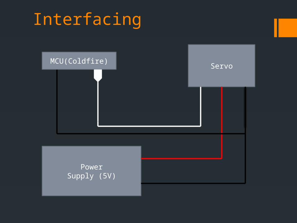
Interfacing
MCU(Coldfire)Servo
PowerSupply (5V)
Registers Used
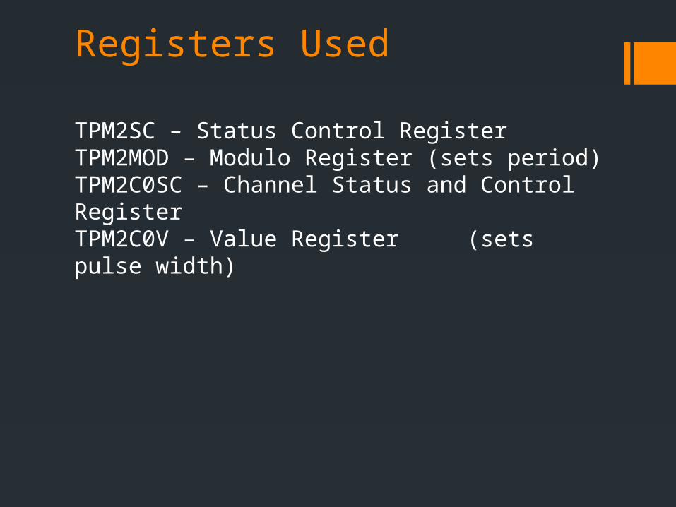
TPM2SC – Status Control RegisterTPM2MOD – Modulo Register (sets period)TPM2C0SC – Channel Status and Control RegisterTPM2C0V – Value Register (sets pulse width)
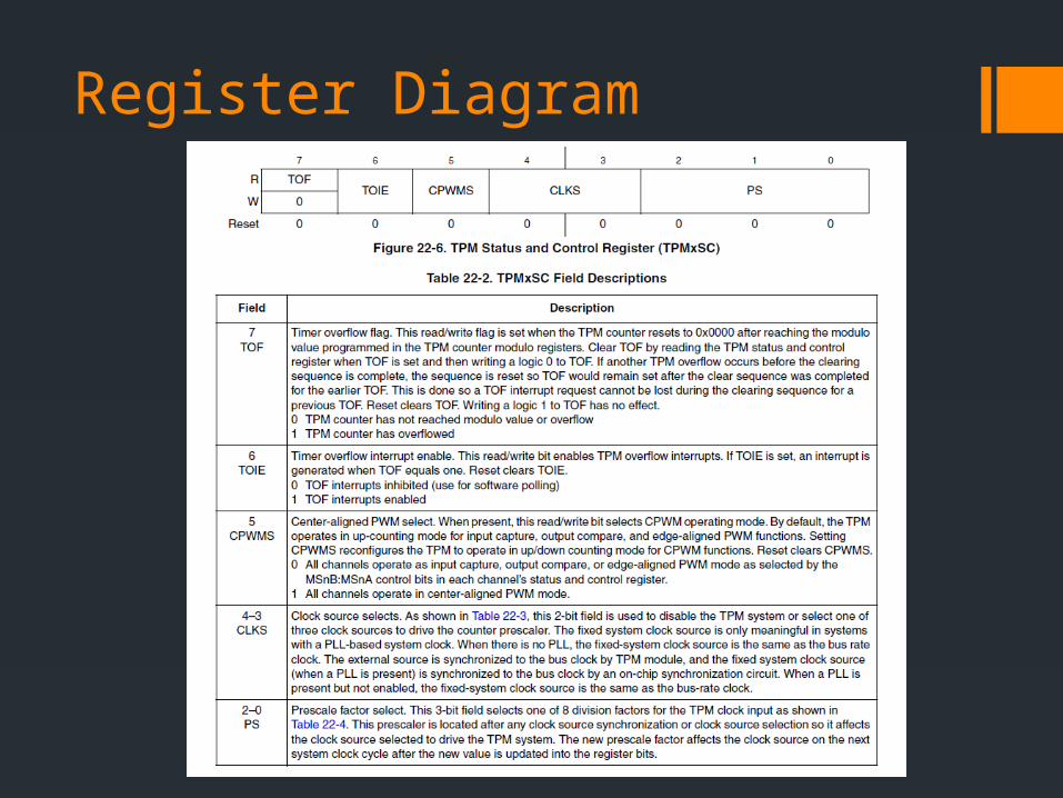
Register Diagram
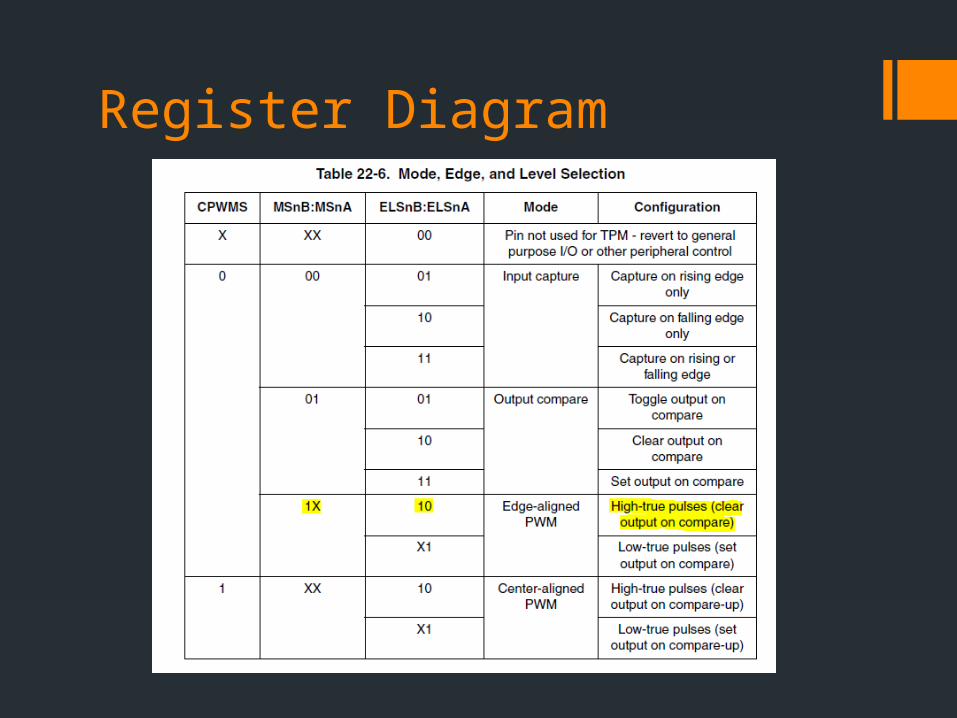
Register Diagram

Analog to Digital ConversionInitialization Select ADC clock source and divide by # bits for conversion
(ADCCFG)
Per Conversion Select channel to convert (ADCSC1) Wait for conversion complete (COCO) Read data from result registers (ADCRx)
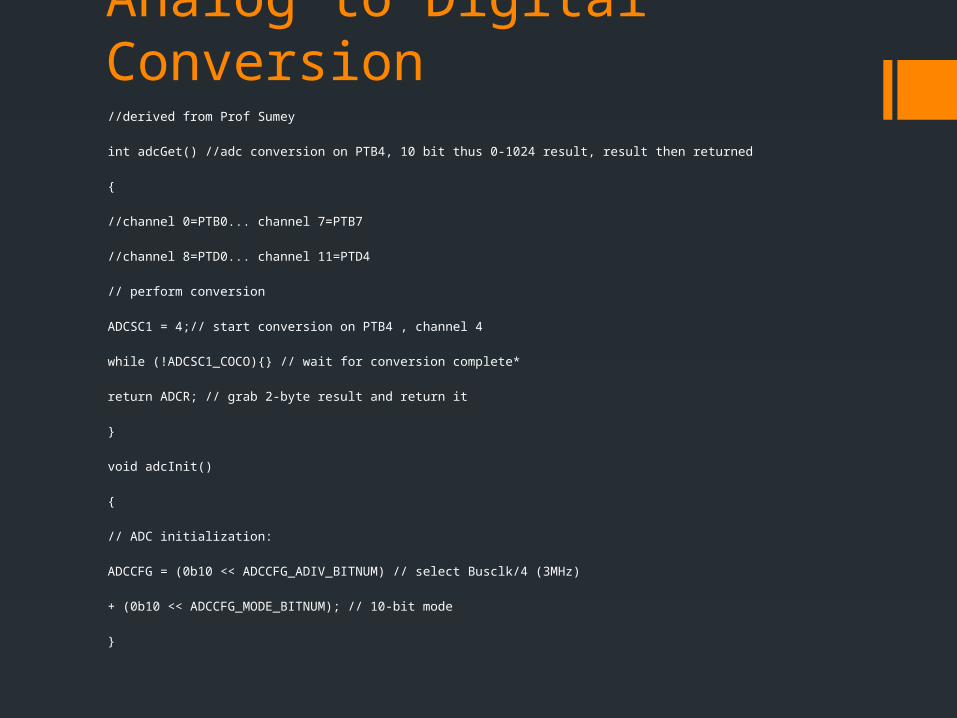
Analog to Digital Conversion//derived from Prof Sumey
int adcGet() //adc conversion on PTB4, 10 bit thus 0-1024 result, result then returned
{
//channel 0=PTB0... channel 7=PTB7
//channel 8=PTD0... channel 11=PTD4
// perform conversion
ADCSC1 = 4;// start conversion on PTB4 , channel 4
while (!ADCSC1_COCO){} // wait for conversion complete*
return ADCR; // grab 2-byte result and return it
}
void adcInit()
{
// ADC initialization:
ADCCFG = (0b10 << ADCCFG_ADIV_BITNUM) // select Busclk/4 (3MHz)
+ (0b10 << ADCCFG_MODE_BITNUM); // 10-bit mode
}
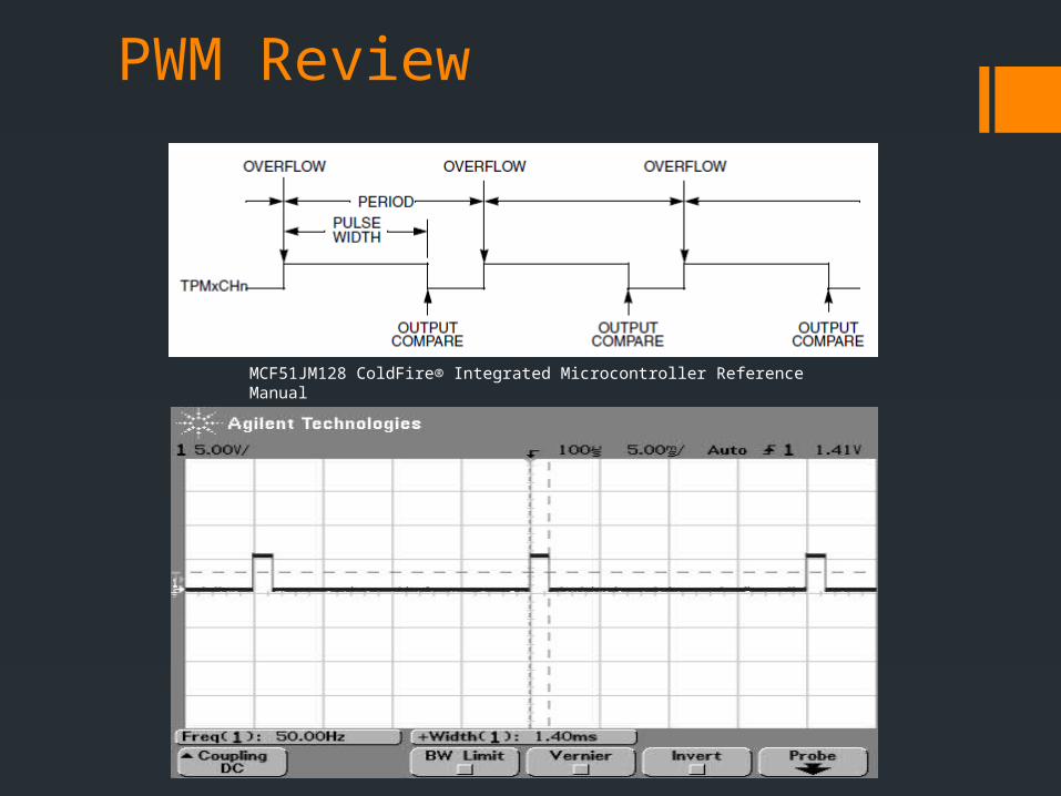
PWM Review
MCF51JM128 ColdFire® Integrated Microcontroller Reference Manual
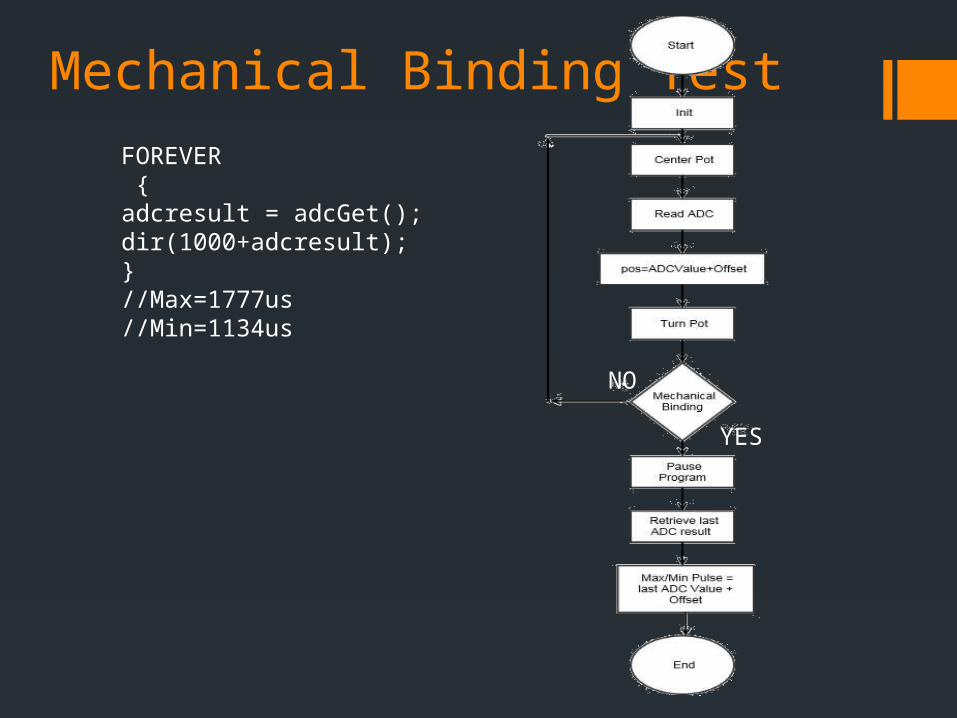
Mechanical Binding Test
NO
YES
FOREVER {adcresult = adcGet();dir(1000+adcresult);}//Max=1777us//Min=1134us
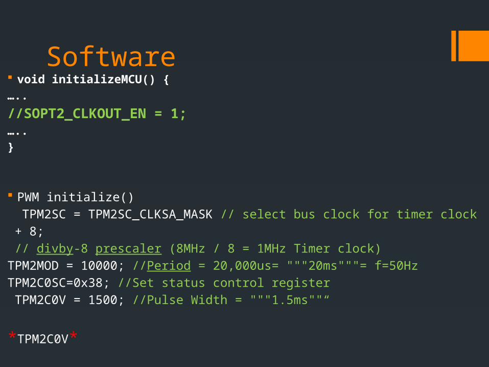
Software void initializeMCU() {
…..
//SOPT2_CLKOUT_EN = 1;…..
}
PWM initialize()
TPM2SC = TPM2SC_CLKSA_MASK // select bus clock for timer clock
+ 8;
// divby-8 prescaler (8MHz / 8 = 1MHz Timer clock)
TPM2MOD = 10000; //Period = 20,000us= """20ms"""= f=50Hz
TPM2C0SC=0x38; //Set status control register
TPM2C0V = 1500; //Pulse Width = """1.5ms""“
*TPM2C0V*
Summary
How to control the car heading via a steering servo

References (1) “S3010 Std. HT Ball Bearing." S3010 Std. HT Ball
Bearing. N.p., n.d. Web. 17 Feb. 2015
(2) “How Do Servos Work?" How Do Servos Work? N.p., n.d. Web. 17 Feb. 2015.
(3) "Futaba S3010 - Standard High-Torque BB Servo." Futaba S3010 Servo Specifications and Reviews. N.p., n.d. Web. 17 Feb. 2015

Questions?


