+ All Categories
Home > Documents > Steering System - Donuts

Steering System - Donuts

Date post: 18-Nov-2021
Category:
Upload: others
View: 2 times
Download: 0 times
Share this document with a friend
38
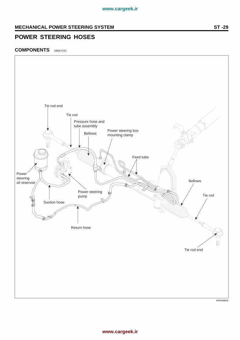
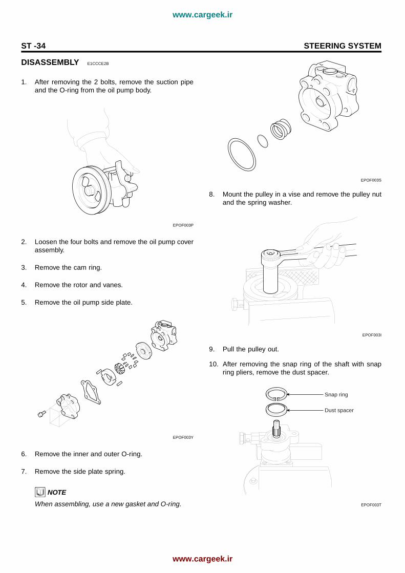
Steering System GENERAL STEERING COLUMN AND SHAFT STEERING COLUMNSHAFT MECHANICAL POWER STEERING SYS- TEM POWER STEERING GEAR BOX POWER STEERING HOSES POWER STEERING OIL PUMP www.cargeek.ir www.cargeek.ir
Transcript

Steering SystemGENERAL

STEERING COLUMN AND SHAFTSTEERING COLUMN/SHAFT

MECHANICAL POWER STEERING SYS-TEM

POWER STEERING GEAR BOXPOWER STEERING HOSESPOWER STEERING OIL PUMP

www.cargeek.ir

www.cargeek.ir

ST -2 STEERING SYSTEM

GENERALSPECIFICATIONS E6E0FAC5

Item SpecificationSteering gear typeRack strokePower steering pump typeOil pump displacement

Rack and pinion132mmVane type9.6 cm³/rev.MAX. (0.59 in³/rev.MAX)

SERVICE STANDARD

Item SpecificationSteering wheel free playSteering angleInner wheelOuter wheelStationary steering effortBelt deflectionNew beltUsed beltOil pump relief pressureTotal pinion preloadTie rod swing resistanceTie rod end ball joint starting torque

0~30 mm (0~1.1 in)

34 76´ ± 230 19´29N (3.0kg, 6.5lbs)

8.8~11.012.5~14.38.3~8.8 MPa (85~90 kg/cm², 1209~1280 psi0.6~1.3 Nm (6~13 kg·cm, 5.2~11.3 lb·in)2~5 Nm (20~50 kg·cm, 1.4~3.6 lb·ft)0.5~2.5 Nm (5~25 kg·cm, 0.36~1.78 lb·ft)

TIGHTENING TORQUE

Item Nm kg·cm lb·ftPower steering column and shaftSteering column and shaft assembly mounting boltPower steering wheel lock nutPinion gear and joint assemblySteering column shaft and universal joint assemblyDust cover mounting bolt

13 ~ 1835 ~ 4515 ~ 2018 ~ 2017 ~ 26

130 ~ 80350 ~ 450150 ~ 200180 ~ 200170 ~ 260

9.6 ~ 13.325.8 ~ 33.2

11 ~ 1513.3 ~ 15

125. ~ 19.2

Power steering gear boxGear box mounting boltTie rod end lock nutTie rod end ball joint and knuckle arm mounting nutFeed tube to gear boxGear box to valve bodyYoke plug lock nut

60 ~ 8050 ~ 5524 ~ 3410 ~ 1620 ~ 3050 ~ 70

600 ~ 800500 ~ 550240 ~ 340100 ~ 160200 ~ 300500 ~ 700

44 ~ 5937 ~ 40.617.7 ~ 257.4 ~ 11.815 ~ 2237 ~ 52

Power steering oil pumpPressure hose to oil pumpOil pump adjusting boltOil pump mounting boltOil pump bracket mounting bolt

55 ~ 6535 ~ 5035 ~ 5035 ~ 50

550 ~ 650350 ~ 500350 ~ 500350 ~ 500

40.6 ~ 47.925.8 ~ 3725.8 ~ 3725.8 ~ 37

Power steering hosePower steering reservoir mounting boltPower steering hose mounting boltPower steering tube mounting bolt

4 ~ 64 ~ 64 ~ 6

40 ~ 6040 ~ 6040 ~ 60

3.0 ~ 4.43.0 ~ 4.43.0 ~ 4.4

www.cargeek.ir

www.cargeek.ir

GENERAL ST -3

LUBRICANTS EB2EEA0C

Recommended lubricant Quantity

Horn contact ring of steering wheel CENTOPLX278(KLUBER KOREA) 1.5g

Bearing of steering shaft ALVANIA #2 or #3(KEUK DONG SHELL, KOREA) As required

Ball joint of tie rod end SHOWA SUNLIGHTMB-2 or equivalent 1.5g

Steering gear housing ONE-LUBER RP GREASE(KYODOYUSHI, JAPAN) As required

Inner ball joint of gear box LONG TIME PD2(OPTIMOL, GERMAN) As required

Contact area of gear box bellows & tie rod SILICON GREASE(SPEC NO : MS511-41) As required

Power steering fluid PSF-3 0.75 ~ 0.8 liter(0.79 ~ 0.84 qts.)

SPECIAL TOOLS ECAE85D3

Tool (Number and name) Illustration Use09222-32100Valve stem oil seal installer

HCT5602

1. Installation of the ball bearingto rack housing

2. Installation of the oil seal to oil pump

09434-14200Counter shaft bearing installer

EPKB040A

Installation of the oil seal to rackbushing and valve body

09555-21000Bar

EPKB040B

Removal and installation the oil seal.

www.cargeek.ir

www.cargeek.ir

ST -4 STEERING SYSTEM

Tool (Number and name) Illustration Use09561-11002Steering wheel puller

HCT5607

Removal of the steering wheel.

09565-31300Yoke plug torque wrench socket

APCD002J

Removal, installation and adjustmentof steering gear yoke plug.

09568-31000Tie rod end puller

EPOF003M

Seperation of the tie rod end ball joint.

09572-21000Oil pressure gauge

EPA9005K

Measurement of the power steeringoil pressure.(use with 09572-22100, 09572-21200)

09572-21200Oil pressure gauge adapter(Hose side)

EPA9005L

Measurement of the power steeringoil pressure.(use with 09572-21000, 09572-22100)

09572-22100Oil pressure gauge adapter(Pump side)

EPA9005M

Measurement of the power steeringoil pressure.(use with 09572-21000, 09572-21200)

www.cargeek.ir

www.cargeek.ir

GENERAL ST -5

Tool (Number and name) Illustration Use09573-21000Oil seal installer guide

EPKB040C

Installation of the oil seal(use with 09573-21100, 09573-21200,09517-11000, 09555-21000)

09573-21100Oil seal installer

EPKB040D

Installation of the oil seal(use with 09573-21000, 09573-21200,09555-21000)

09573-21200Oil seal guide

EPKB040E

Removal and installation of the oil seal

www.cargeek.ir

www.cargeek.ir

ST -6 STEERING SYSTEM

TROUBLESHOOTING ED69292A

POWER STEERING

Symptom Probable cause Remedy

Excessive play in steeringwheel

Loose yoke plugLoose steering gear mounting boltsLoose or worn tie rod end

RetightenRetightenRetighten or place asnecessary

Steering wheel operationis not smooth (Insufficientpower assist)

V-belt slippageDamaged V-beltLow fluid levelAir in the fluidTwisted or damaged hosesInsufficient oil pump pressureSticky flow control valveExcessive internal oil pump leakageExcessive oil leaks from rack and pinion in gear boxDistorted or damaged gear box or valve body seale

ReadjustReplaceReplenishBleed airCorrect the rougting orreplaceRepair or replace theoil pumpReplaceReplace the damaged partsReplace the damaged partsReplace

Steering wheel does notreturn properly

Excessive turning resistance of tie-rod endYoke plug excessively tightInner tie rod and/or ball joint cannot turn smoothlyLoose mounting of gear box and crossmemberWorn steering shaft joint and/or body grommetDistorted rackDamaged pinion bearingTwisted or damaged hosesDamaged oil pressure control valveDamaged oil pump input shaft bearing

ReplaceAdjustReplaceRetightenCorrect or replaceReplaceReplaceReposition or replaceReplaceReplace

Noise

Hissing Noise in Steering GearThere is some noise with all power steering systems.One of the most common is a hissing sound when thesteering wheel is turned and the car is not moving.This noise will be most evident when turning the wheelwhile the brakes are being applied.There is no relationship between this noise andsteering performance.Do not replace the valve unless the "hissing"noise becomes extreme.A replaced valve will also make a slight noise, and isnot always a solution for the condition.

Rattling or chucking noisein the rack and pinion

Interference with hoses from vehicle bodyLoose gear box bracketLoose tie rod end and/or ball jointWorn tie rod and/or ball joint

RepositionRetightenRetightenReplace

Noise in the oil pumpLow fluid levelAir in the fluidLoose pump mounting bolts

ReplenishBleed airRetighten

www.cargeek.ir

www.cargeek.ir

GENERAL ST -7

SERVICE ADJUSTMENTPROCEDURE E6BBFE1D

CHECKING STEERING WHEEL FREE PLAY

1. Start the engine with the steering wheel in the straightahead position.

2. Measure the play at the circumference of the steeringwheel.

Standard valueSteering wheel free play : 0~30 mm (0~1.1 in)

0~30mm

EPOF011A

3. If the play exceeds the standard value, inspect theconnection between the steering shaft and steeringlinkage.

CHECKING STEERING ANGLE

1. Place the front wheel on a turning radius gauge andmeasure the steering angle.

Standard valueWheel angleInner wheel : 34 76´ ± 2Outer wheel : 30 19´

EPOF001A

2. If the measured value is not within the standard value,adjust the toe and inspect again.

CHECKING THE TIE ROD END BALL JOINTSTARTING TORQUE

1. Disconnect the tie rod and knuckle by using the spe-cial tool.

09568-31000

EPOF001B

2. Move the ball joint stud in a circular motion severaltimes to check for looseness.

www.cargeek.ir

www.cargeek.ir

ST -8 STEERING SYSTEM

3. Mount the nuts on the ball joint, and then measure theball joint starting torque.

Standard value0.5~2.5 Nm (5~25 kg·cm, 0.36~1.78 lb·ft)

EPOF013N

4. If the starting torque exceeds the upper limit of thestandard value, replace the tie rod end.

5. Even if the starting torque is below the lower limit ofthe standard value, check the play of the ball joint andreplace if necessary.

CHECKING STATIONARY STEERING EFFORT

1. Position the vehicle on a level surface and place thesteering wheel in the straight ahead position.

2. Increase the engine speed to 1000 ± 100 rpm.

NOTEAfter checking, reset the engine speed to the standardvalue (idling speed).

3. Measure the turning force with a spring scale by turn-ing the steering wheel clockwise and counterclock-wise one and a half turns.

Standard valueStationary steering effort : 29 N (3.0 kg, 6.5lbs)

4. Check that there is no sudden change of force whileturning the steering wheel.

5. If the stationary steering effort is excessive, check andadjust the following points.

1) Damage or cracks on the dust cover and tie rodend ball joint.

2) Pinion preload of the steering gear box and start-ing torque of the tie rod end ball joint.

3) Starting torque of the ball joint.

CHECKING STEERING WHEEL RETURN

Check the steering wheel return and confirm the followingpoints :

1. The force required to turn the steering wheel and thewheel return should be the same for both left and rightin case of moderate or sharp turns.

2. When the steering wheel is turned 90 and held fora couple of seconds while the vehicle is being drivenat 35kph, the steering wheel shouldreturn at least 70from the neutral position when it is released.

NOTEIf the steering wheel is turned very quickly, steeringmay be momentarily difficult. This is not a malfunc-tion because the oil pump output will be somewhat-decreased.

Central position

EPOF003N

www.cargeek.ir

www.cargeek.ir

GENERAL ST -9

CHECKING POWER STEERING BELT TENSION

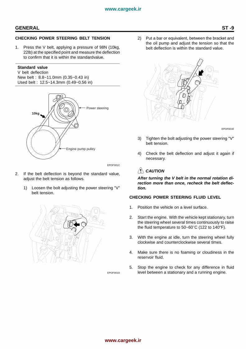
1. Press the V belt, applying a pressure of 98N (10kg,22lb) at the specified point and measure the deflectionto confirm that it is within the standardvalue.

Standard valueV belt deflectionNew belt : 8.8~11.0mm (0.35~0.43 in)Used belt : 12.5~14.3mm (0.49~0.56 in)

10kg

Power steering

Engine pump pulley

EPOF001C

2. If the belt deflection is beyond the standard value,adjust the belt tension as follows.

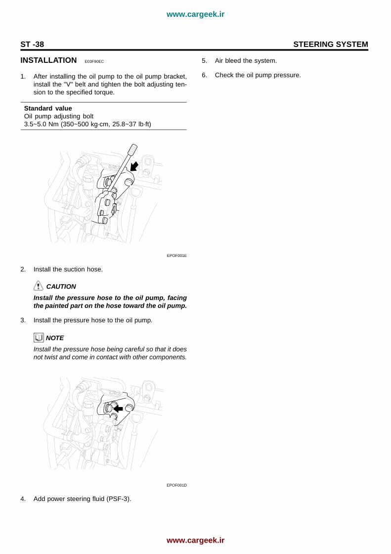
1) Loosen the bolt adjusting the power steering "V"belt tension.

EPOF001D

2) Put a bar or equivalent, between the bracket andthe oil pump and adjust the tension so that thebelt deflection is within the standard value.

EPOF001E

3) Tighten the bolt adjusting the power steering "V"belt tension.

4) Check the belt deflection and adjust it again ifnecessary.

CAUTIONAfter turning the V belt in the normal rotation di-rection more than once, recheck the belt deflec-tion.

CHECKING POWER STEERING FLUID LEVEL

1. Position the vehicle on a level surface.

2. Start the engine. With the vehicle kept stationary, turnthe steering wheel several times continuously to raisethe fluid temperature to 50~60 C (122 to 140 F).

3. With the engine at idle, turn the steering wheel fullyclockwise and counterclockwise several times.

4. Make sure there is no foaming or cloudiness in thereservoir fluid.

5. Stop the engine to check for any difference in fluidlevel between a stationary and a running engine.

www.cargeek.ir

www.cargeek.ir

ST -10 STEERING SYSTEM

NOTE1. If the fluid level varies 5mm (0.2 in) or more, bleed

the system again.2. If the fluid level suddenly rises after stopping the

engine, further bleeding is required.3. Incomplete bleeding will produce a chattering

sound in the pump and noise in the flow controlvalve, and lead to decreased durability of thepump.

MAX

MIN

EPOF011E

REPLACING POWER STEERING FLUID

1. Jack up the front wheels and support them with rigidracks.

2. Disconnect the return hose from the oil reservoir andplug the oil reservoir.

3. Connect a vinyl hose to the disconnected return hose,and drain the oil into a container.

4. Disconnect the high-tension cable at the ignition coilside.While operating the starter motor intermittently, turnthe steering wheel all the way to the left and then tothe right several times to drain the fluid.

5. Connect the return hose and fix it with a clip securely.

6. Fill the power steering fluid reservoir with the specifiedfluid.

PSF-3 : 0.75~0.8 lit.

7. Start the engine.

8. Check for fluid leaks from the hose, then stop the en-gine.

9. Pour the fluid into the bottom of the oil filter in thepower steering fluid reservoir.

10. Bleed the air.

AIR BLEEDING

1. Disconnect the ignition coil high tension cable, andthen, while operating the starter motor intermittently(for 15 to 20 seconds), turn the steering wheel all theway to the left and then to the right five or six times.

NOTE1. During air bleeding, replenish with the fluid so

that the level does not fall below the lower po-sition of the filter.

2. If air bleeding is done while the vehicle is idling,the air will be broken up and absorbed into thefluid. Be sure to do the bleeding only while crank-ing.

2. Connect the high tension cable, and then start theengine (idling).

3. Turn the steering wheel to the left and then to the right,until there are no air bubbles in the oil reservoir.

4. Confirm that the fluid is not milky and that the level isbetween "MAX" and "MIN" marks on the reservoir.

5. Check that there is a little change in the fluid levelwhen the steering wheel is turned left and right.

NOTE1. If the fluid level varies 5mm (0.2 in.) or more,

bleed the system again.2. If the fluid level suddenly rises after stopping the

engine, further bleeding is required.3. Incomplete bleeding will produce a chattering

sound in the pump and noise in the flow controlvalve, and lead to decreased durability of thepump.

MAX

5mm

MIN

EPOF011F

www.cargeek.ir

www.cargeek.ir

GENERAL ST -11

OIL PUMP PRESSURE TEST

1. Disconnect the pressure hose from the pump. Con-nect the special tool between the pump and the pres-sure hose as illustrated.

Temperturegauge

Oil pump

Pressurehose

Oil pressure gauge(09572-21000)

Adapter(09572-22100)

Oil pressuregauge adapter(09572-21200)

Oil pumprelief presure

Reservor

Shut-off valve(close)

EPOF001F

2. Bleed the air, and then start the engine and turn thesteering wheel several times so that the fluid temper-ature can rise to approximately 50~60 C (122~132 F)operating temperature.

3. Increase the engine speed to 1,000 ± 100 rpm.

4. Close the shut-off valve of the special tool and mea-sure the fluid pressure to confirm that it is within thestandard value range.

Standard valueRelief pressure :8.3~8.8 MPa (85~90 kg.cm², 1209~1280 psi)

CAUTIONDo not keep the shut-off valve on the pressuregauge closed for more than ten seconds.

5. Remove the special tools, and tighten the pressurehose to the specified torque.

Tightening torque55~65 Nm (550~650 kg·cm, 40.6~47.9 lb·ft)

6. Bleed the system.

www.cargeek.ir

www.cargeek.ir

ST -12 STEERING SYSTEM

STEERING COLUMN ANDSHAFT

STEERING COLUMN/SHAFT

COMPONENTS EB6BCFE5

Key lock assembly

Dust cover assembly

Steering wheel

Universal joint assembly

Steering column shaft �mounting bolt

Steering colum shaftassembly

Tilt lever

Steering column lower shroud

Steering column upper shroud

Clock spring

Multifunctionswitch

KPKA010A

www.cargeek.ir

www.cargeek.ir

STEERING COLUMN AND SHAFT ST -13

REMOVAL EBF7A8B6

1. Disconnect the negative (-) terminal from the battery.

EPOF011G

2. After removing the bolts in the illustration, remove thedriver’s airbagmodule.

NOTEFor the vehicles not equipped with SRS airbag, re-move the horn coverassembly.

3. Remove the steering wheel lock nut.

EPOF001G

4. After aligning the marks on the steering shaft andwheel, remove thesteering wheel using the specialtool.

NOTEDo not hammer on the steering wheel to remove it,Doing so it may damagethe steering column.

09561-11002

EPOF001H

5. After removing the 3 bolts in the illustration, removethe steeringcolumn shroud.

EPOF001I

6. Remove the connectors of the multifunction switchand the multifunctionswitch assembly.

EPOF001J

www.cargeek.ir

www.cargeek.ir

ST -14 STEERING SYSTEM

7. Remove the lower crash pad after loosening themounting bolts.

Lower crash pad

EPOF001K

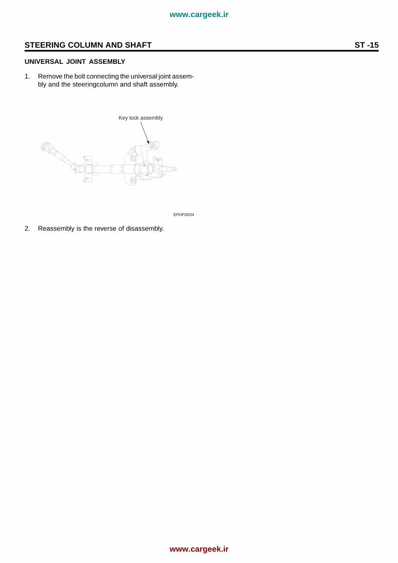
8. Remove the bolts connecting the steering columnshaft, the universaljoint and the pinion.

EPOF001L

9. After removing the mounting bolts and nuts, removethe steering columnand shaft assembly.

INSPECTION E6B1069E

1. Check the steering column shaft for damage and de-formation.

2. Check connections for play, damage and smooth op-eration.

3. Check the ball joint bearing for wear and damage.

INSTALLATION E66649F3

Assembly is the reverse of removal.

DISASSEMBLY AND REASSEMBLY E413FF0D

KEY LOCK ASSEMBLY

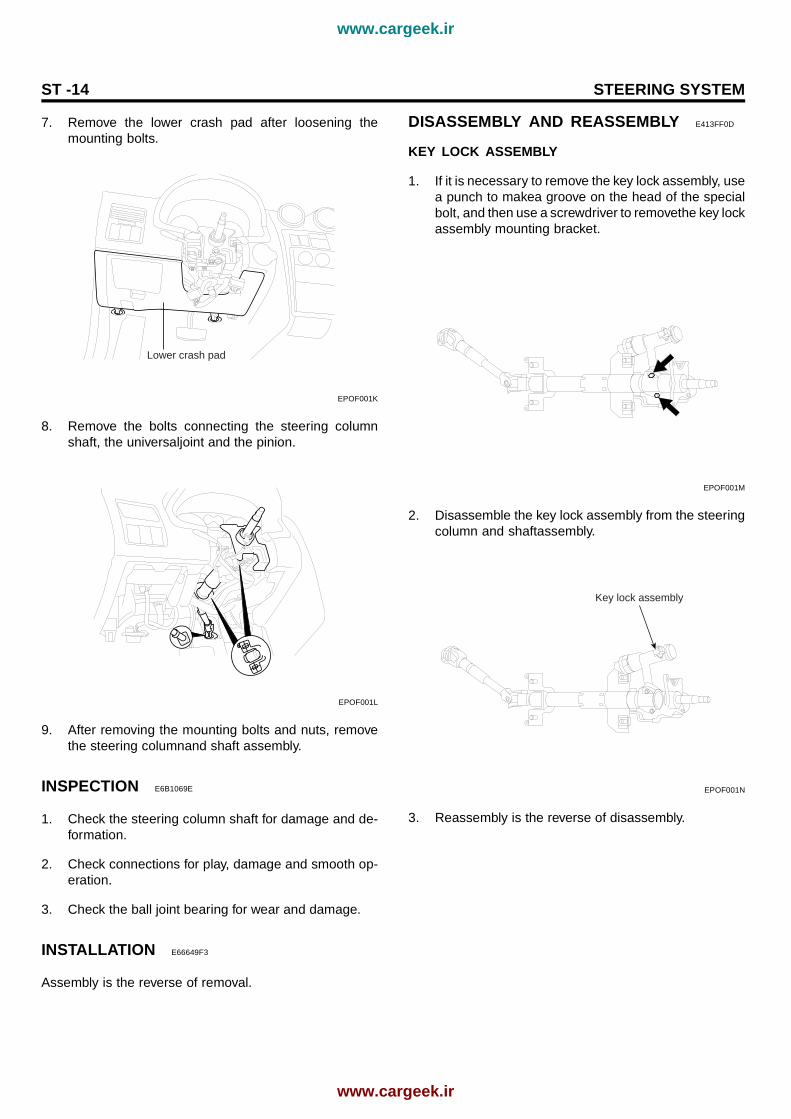
1. If it is necessary to remove the key lock assembly, usea punch to makea groove on the head of the specialbolt, and then use a screwdriver to removethe key lockassembly mounting bracket.

EPOF001M

2. Disassemble the key lock assembly from the steeringcolumn and shaftassembly.

Key lock assembly

EPOF001N

3. Reassembly is the reverse of disassembly.

www.cargeek.ir

www.cargeek.ir

STEERING COLUMN AND SHAFT ST -15

UNIVERSAL JOINT ASSEMBLY

1. Remove the bolt connecting the universal joint assem-bly and the steeringcolumn and shaft assembly.

Key lock assembly

EPOF001N

2. Reassembly is the reverse of disassembly.

www.cargeek.ir

www.cargeek.ir

ST -16 STEERING SYSTEM

MECHANICAL POWERSTEERING SYSTEM

POWER STEERING GEAR BOX

COMPONENTS E935F827

[ VIEW A ] [ VIEW B ] [ VIEW C ]

Tie rod endassembly

Slotted nut

Split pin

Tie rod end assembly

Tie rod assembly

Bellows

Feed tube

Power steering gear boxmounting clamp

Rack housing

Steering columnassembly

Joint assembly

Dust cover

Tie rod end assembly

Tie rod assembly

Valve body assembly

C

B

A

A

B

EPKB170A

www.cargeek.ir

www.cargeek.ir

MECHANICAL POWER STEERING SYSTEM ST -17

DISASSEMBLY AND ASSEMBLY E4833D6D

Feed tube Valve bodyhousing

Bolt

Yoke plug

Lock nut

Oil seal

Rack housing

Power steering gear boxmounting clamp

Oil seal

Rack supportspring

Rack support yoke

Pinion valveassembly

Rack

Oil seal

Tie rod end

Lock nut

Dust cover

Bellows clip

Bellows

Bellows band

Tie rod

Circlip

Oil sealRack stopper

KPKA033A

www.cargeek.ir

www.cargeek.ir

ST -18 STEERING SYSTEM

REMOVAL E5D340F0

1. Detach the power steering pressure hose mountingclamp and the return tube mounting clamp.

2. Drain the power steering fluid.

3. Disconnect the pressure tube and the return tube fit-tings from the gear box.

4. Disconnect the shaft assembly from the gear box in-side the passenger compartment.

EPOF001O

5. Remove the strap and push out the dust cover andremove the dust cover mounting plate.

6. Raise up the vehicle.

7. Remove the front tires (RH/LH).

8. After removing the split pin, disconnect the tie rodfrom the knuckle by using the special tool (09568-31000).

09568-31000

EPOF001B

9. Remove the stabilizer bar (RH side) mounting bracketand link nut.

EPOF001P

10. After removing the rear roll stopper bracket mountingbolt from the sub frame, remove the rear roll stopper.

EPOF001Q

11. After loosing the sub frame mounting bolts a little soas to be the sub frame assembly hung down slightly.

EPOF001R

www.cargeek.ir

www.cargeek.ir

MECHANICAL POWER STEERING SYSTEM ST -19

12. Remove the power steering gear box mounting bolts,pressure tube and the return tube clamp.

EPOF001S

13. Pull the power steering gear box assembly toward theright side of the vehicle.

NOTEWhen removing the gear box, pull it out carefully andslowly to avoid damaging.

EPOF011S

INSPECTION AND ADJUSTMENT BEFOREDISASSEMBLY EF650ECD

Fix a brass plate or aluminum plate for protection to thejaws of a vise and mount the gear box in a vise.

CAUTIONWhen mounting the gear box in a vise, let the in-stallation section of it be fixed to the jaws. If othersection is fixed, the gear box may be damaged.

EPOF001T

TOTAL PINION PRELOAD

1. Rotate the pinion gear for approximately 4 to 6seconds for one rotation to measure the total pinionpreload.

Standard valueTotal pinion preload :0.6~1.3 Nm (6~13 kg·cm, 0.4~1.0 lb·ft)

NOTEMeasure the pinion preload through the entire strokeof the rack.

EPOF001U

2. If the measured value is out of specifications, firstadjust the yoke plug, then recheck the total pinionpreload.

3. If not obtain the total pinion preload after adjusting theyoke plug check or replace the yoke plug components.

www.cargeek.ir

www.cargeek.ir

ST -20 STEERING SYSTEM

TIE ROD SWING RESISTANCE

1. Rotate the tie rod severely ten times.

2. Measure the tie rod swing resistance with a springscale.

Standard valueTotal rod swing resistance :2~5 Nm (20~50 kg·cm, 1.4~3.6 lb·ft)

EPOF001V

3. If the measured value exceeds the standard value,replace the tie rod assembly.

CAUTIONEven if the measured value is below the standardvalue, the tie rod that swings smoothly withoutexcessive play may be used. If the measuredvalueis below 0.44 kg·cm, replace the tie rod.

BELLOWS INSPECTION

1. Inspect the bellows for damage or deterioration.

2. Make sure the bellows are secured in the correct po-sition.

3. If the bellows are defective, replace them with newones.

DISASSEMBLY EB4351BB

1. Remove the tie rod end from the tie rod.

EPOF001W

2. After mounting the tie rod end in a vise, remove thedust cover from the ball joint.

EPOF001X

3. Remove the bellows band.

EPOF001Y

www.cargeek.ir

www.cargeek.ir

MECHANICAL POWER STEERING SYSTEM ST -21

4. Remove the bellows clip.

EPOF001Z

5. Pull the bellows out toward the tie rod.

NOTECheck for rust on the rack when the bellows are re-placed.

6. Remove the feed tube from the rack housing.

7. While moving the rack slowly, drain the fluid from therack housing.

8. Unstake the tab washer which fixes the tie rod andrack with a chisel.

EPOF002A

9. Remove the tie rod from the rack.

CAUTIONRemove the tie rod from the rack, taking care notto twist the rack.

EPOF002B

10. Remove the yoke plug locking nut.

EPOF002C

11. Remove the yoke plug with a 14mm socket.

EPOF002D

www.cargeek.ir

www.cargeek.ir

ST -22 STEERING SYSTEM

12. Remove the lock nut, yoke plug, rack support spring,rack support yoke and bushing from the gear box.

Lock nutYoke plug

Rack support spring

Rack support yokeBushing

EPOF002E

13. Remove the valve body housing by loosening the twobolts.

EPOF002F

14. Turn the rack stopper clockwise until the end of thecirclip comes out of the slot in the rack housing.

Circlip

Rack stopper

EPOF002G

15. When the end of the circlip comes out of the notchedhole of the housing rack cylinder, turn the rack stoppercounterclockwise and remove thecirclip.

CAUTIONBe careful not to damage the rack.

Circlip

Rack stopper

EPOF002H

16. Remove the rack stopper, rack bushing and rack fromthe rack housing.

17. Remove the O-ring from the rack bushing.

EPOF002I

www.cargeek.ir

www.cargeek.ir

MECHANICAL POWER STEERING SYSTEM ST -23

18. Remove the oil seal from the rack bushing.

Rack bushing

Oil seal

EPOF002J

19. Remove the valve body from the valve body housingwith a soft hammer.

EPOF002K

20. Using the special tool, remove the oil seal and ballbearing from the valve body housing.

21. Remove the oil seal and O-ring from the rack housing.

CAUTIONBe careful not to damage the pinion valve cylinderbore of the rack housing.

22. Using the special tool, remove the oil seal from therack housing.

CAUTIONBe careful not to damage the rack cylinder bore ofthe rack housing.

09573-21200

09555-21000

Back-up washer

Oil seal

EPOF002L

INSPECTION EB28A729

1. Rack

1) Check for rack tooth face damage or wear

2) Check for oil seal contact surface damage

3) Check for rack bending or twisting

4) Check for oil seal ring damage or wear

5) Check for oil seal damage or wear

Vent hole

EPOF002M

www.cargeek.ir

www.cargeek.ir

ST -24 STEERING SYSTEM

2. Pinion valve

1) Check for pinion gear tooth face damage or wear

2) Check for oil seal contact surface damage

3) Check for seal ring damage or wear

4) Check for oil seal damage or wear

EPOF002P

3. Bearing

1) Check for seizure or abnormal noise during abearing rotation

2) Check for excessive play

3) Check for missing needle bearing rollers

4. Others

1) Check for damage of the rack housing cylinderbore

2) Check for boot damage, cracking or aging

REASSEMBLY E6FCFC24

1. Apply the specified fluid to the entire surface of therack oil seal.

Recommended fluid : PSF-3

2. Install the oil seal to the specified position in the rackhousing.

09573-2120009573-21000

09555-21000

09573-21100

EPOF002N

3. Apply the specified fluid to the entire surface of therack bushing oil seal.

Recommended fluid : PSF-3

4. Install the oil seal in the rack bushing.

09434-14200

O-ring

EPOF002O

5. Apply the specified fluid to the entire surface of theO-ring and install it in the rack bushing.

www.cargeek.ir

www.cargeek.ir

MECHANICAL POWER STEERING SYSTEM ST -25

6. Apply the specified grease to the rack teeth.

Recommended greaseMultipurpose grease SAE J310a, NLGI #2 EP

NOTEDo not plug the vent hole in the rack with grease.

Vent hole

EPOF002M

7. Insert the rack into the rack housing and install therack bushing and rack stopper.

Rack bushing

Rack stopper

Rack

EPOF002Q

8. Push in the rack stopper until the circlip groove of therack stopper is aligned with the notched hole of therack housing. Install the circlip while turning the rackstopper.

CAUTIONThe circlip end should not be visible through thenotched hole of the rack housing.

Slot

Circlip

Circlip position

EPOF002R

9. Using a special tool, install the oil seal and the ballbearing in the valve body housing.

EPOF002S

www.cargeek.ir

www.cargeek.ir

ST -26 STEERING SYSTEM

10. After applying the specified fluid and grease to thepinion valve assembly, install it in the rack housingassembly.

EPOF002T

11. After applying the specified fluid to the oil seal, installit in the rack housing, and fix the valve body assemblyand O-ring in the gear box.

EPOF002U

12. Install the tab washer and the tie rod and stake thetab washer end at two points over the tie rod.

Tab washer

EPOF002V

13. Install the bushing, rack support yoke, rack supportspring and yoke plug in the order shown in the illus-tration. Apply semi-drying sealantto the threaded sec-tion of the yoke plug before installation.

Lock nutYoke plug

Rack support spring

Rack support yokeBushing

EPOF002E

14. With the rack placed in the center position, attachthe yoke plug to the rack housing. Tighten the yokeplug to 12 Nm (120 kg·cm, 8.9 lb·ft), with a 14mmsocket. Loosen the yoke plug approximately from 30to 60 and tighten the yoke nut to the specified torque.

Tightening torque50~70 Nm (500~700 kg·cm, 37~52 lb·ft)

09565-31300

EPOF002W

15. Tighten the feed tube to the specified torque and in-stall the mounting rubber using adhesive.

www.cargeek.ir

www.cargeek.ir

MECHANICAL POWER STEERING SYSTEM ST -27

16. Apply the specified grease to the bellows mountingposition (fitting groove) of the tie rod.

Recommended grease :Silicone grease

EPOF002X

17. Install the new attaching band to the bellows.

NOTEWhen the bellows are installed, a new band must beused.

18. Install the bellows in position, taking care not to twistit.

19. Fill the dust cover inner side and lip with the specifiedgrease, and fix the dust cover in position with the clipring attached in the grooveof the tie rod end.

Recommended greaseA : POLY LUB GLY 801K or equivalentB : SHOWA SUNLIGHT MB2 or equivalentDust cover inner side and lip : THREE BOND

Grease A

Gease B

Sealant

EPOF002Y

20. Install the tie rods so that the length of the left andright tie rods equals the standard value.

Standard valueTie rod free length : 204.5mm

Locking nut

204.5 mm

EPOF002Z

21. Check for total pinion preload.

www.cargeek.ir

www.cargeek.ir

ST -28 STEERING SYSTEM

INSTALLATION EA73705C

1. Push in the power steering gear box assembly in theright side of the vehicle.

EPOF011S

2. Install the dust cover mounting plate.

3. Connect the dust cover to its mounting plate with anew strap.

4. Connect the steering gear box assembly to the steer-ing column and shaft assembly.

EPOF001D

5. Installation is the reverse of removal.

6. After installation, bleed the system.

www.cargeek.ir

www.cargeek.ir

MECHANICAL POWER STEERING SYSTEM ST -29

POWER STEERING HOSES

COMPONENTS EB5E7C5C

Tie rod end

Tie rod

Pressure hose andtube assembly

BellowsPower steering boxmounting clamp

Feed tube

Power �steeringoil reservoir

Power steeringpump

Suction hose

Return hose

Bellows

Tie rod

Tie rod end

KPKA064A

www.cargeek.ir

www.cargeek.ir

ST -30 STEERING SYSTEM

REMOVAL AND INSTALLATION E840C33A

While installing the tube and hose assembly, be sure toalign white marks on each fitting.

White line

EPOF003O

PRESSURE HOSE AND TUBE

1. After draining the power steering fluid, remove thepressure hose mounting clamp.

2. Lift up the vehicle and remove the mounting clampwhich is holding both the pressure tube and the returntube.

EPOF001S

3. Detach the pressure tube fitting in the gear box.

4. Lower the vehicle and remove the connector.

EPOF003A

5. Remove the pressure hose and tube assembly.

EPOF003B

6. Installation is the reverse of removal.

NOTE1. Install the pressure hose and tube so that they

are not twisted and they do not come in contactwith any other parts.

2. After installation, bleed the system.

www.cargeek.ir

www.cargeek.ir

MECHANICAL POWER STEERING SYSTEM ST -31

RETURN TUBE AND HOSE

1. Detach the hose from the power steering fluid reser-voir.

EPOF003C

2. Remove the return tube and hose mounting clamps.

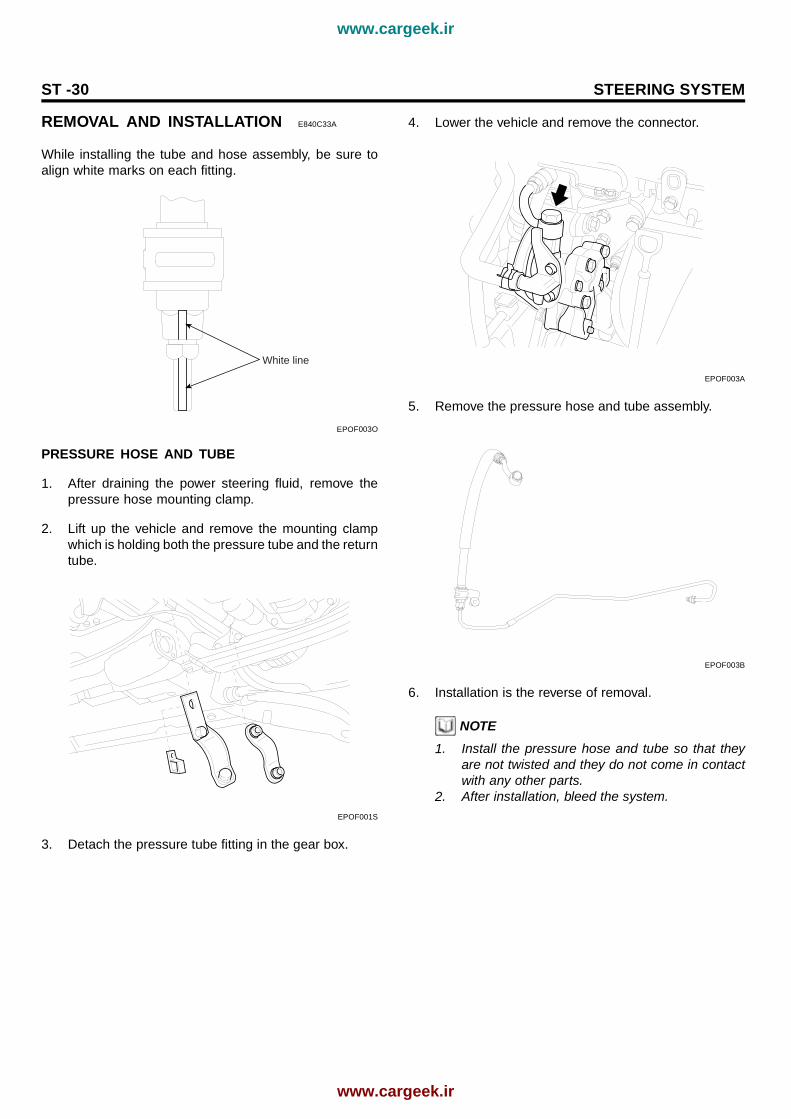
3. Raise the vehicle and remove the mounting clampwhich is holding both the pressure tube and the returntube.

EPOF001S

4. Remove the pressure tube and the return tube fittingin the gear box.

5. Lower the vehicle and disconnect the clamp holdingthe return tube and hoses.

6. Remove the return tube and hoses.

EPOF003D

7. Installation is the reverse of removal.

NOTE1. Install the return tube and hoses so that they are

not twisted and they do not come in contact withany other parts.

2. After installation, air bleed the system.

INSPECTION E169AA01

1. Twisting the hose by hand, check for cracks.

2. Check that the hose does not contact with other com-ponents

HOW TO FILL WITH POWER STEERING FLUID

1. Fill the power steering reservoir with the power steer-ing fluid to the "Max." position.

2. Lift the front wheels with a jack and turn the steeringwheel fully to the left and right, 5~6 times for 15~20sec., while driving the pulleyonly by operating the startmotor.

3. Start the engine, let it idle and turn the steering wheelfully left and right several times until bubbles disap-pear from the power steering reservoir.

4. If the oil color does not become milk-white and the oillevel is constant at the "MAX" position, fluid level isO.K.

CAUTIONIf the oil level changes when turning the steer-ing wheel, and the oil overflows when stoppingthe engine, it shows that air bleeding wasn’t per-formed perfectly. As it can cause noise and earlydamage, you must repeat the aboveprocedures.

www.cargeek.ir

www.cargeek.ir

ST -32 STEERING SYSTEM

POWER STEERING OIL PUMP

COMPONENTS E5C581AE

Pulley nut

Pulley

Snap ring

Bearing

Driveshaft

Oil seal

Front housing

Suction pipe

Connector

Slide platespring

O-ring (Outer)

O-ring (Inner)Oil pump side plate

Vane

Rotor

Cam ring

Lock pin

Gasket

Mounting bolt

Oil pumpcover assembly

EPKB270A

www.cargeek.ir

www.cargeek.ir

MECHANICAL POWER STEERING SYSTEM ST -33

REMOVAL EFA42E9A

1. Remove the pressure hose from the oil pump.Disconnect the suction hose from the suction connec-tor and drain the fluid into a container.

EPOF003C

2. Loosen the power steering "V" belt tension adjustingbolt.

EPOF001D

3. Remove the "V" belt from the power steering oil pumppulley.

EPOF003G

4. After remove the power steering oil pump mountingbolts and the tension adjusting bolt, remove the powersteering oil pump assembly.

EPOF003P

5. Remove the power steering oil pump mountingbracket.

EPOF003H

www.cargeek.ir

www.cargeek.ir

ST -34 STEERING SYSTEM

DISASSEMBLY E1CCCE2B

1. After removing the 2 bolts, remove the suction pipeand the O-ring from the oil pump body.

EPOF003P

2. Loosen the four bolts and remove the oil pump coverassembly.

3. Remove the cam ring.

4. Remove the rotor and vanes.

5. Remove the oil pump side plate.

EPOF003Y

6. Remove the inner and outer O-ring.

7. Remove the side plate spring.

NOTEWhen assembling, use a new gasket and O-ring.

EPOF003S

8. Mount the pulley in a vise and remove the pulley nutand the spring washer.

EPOF003I

9. Pull the pulley out.

10. After removing the snap ring of the shaft with snapring pliers, remove the dust spacer.

Snap ring

Dust spacer

EPOF003T

www.cargeek.ir

www.cargeek.ir

MECHANICAL POWER STEERING SYSTEM ST -35

11. Tap the rotor side of the shaft slighty with a plastichammer to remove the shaft.

EPOF003U

12. Remove the oil seal from the oil pump body.

EPOF003W

13. Remove the connector from the oil pump body, andtake out the flow control valve and the flow controlspring.

14. Remove the O-ring from the connector.

CAUTIONDo not disassemble the flow control valve.

EPOF003X

INSPECTION E01CC83E

1. Check the free length of the flow control spring.

Free length of the flow control spring : 36.5mm

EPOF003R

2. Check that the flow control valve is not bent.

3. Check the shaft for wear and damage.

4. Check the V-belt for wear and deterioration.

5. Check the grooves of the rotor and vanes for stratifiedabrasion.

6. Check the contact surface of the cam ring and vanesfor stratified abrasion.

7. Check vanes for damage.

8. Check that there is no striped wear in the side plate orcontacting part between the shaft and the pump coversurface.

www.cargeek.ir

www.cargeek.ir

ST -36 STEERING SYSTEM

REASSEMBLY EFB7AD5E

1. Install the flow control spring, the flow control valveand the connector into the pump body.

EPOF003X

2. Install the oil seal in the pump body by using the spe-cial tool.

09222-32100

EPOF003Z

3. After inserting the shaft assembly into the pump body,install the dust spacer and snap ring.

EPOF004A

Snap ring

Dust spacer

EPOF003T

4. Install the pump pulley.

EPOF003I

5. Install the spring and inner O-ring.

6. Insert the outer O-ring in the oil pump side plate andthen install it in the pump body.

O-ringFront side plate

Spring

EPOF003J

www.cargeek.ir

www.cargeek.ir

MECHANICAL POWER STEERING SYSTEM ST -37

7. After inserting the lock pin into the groove of the fronthousing, install the cam ring attending to the direction.

Front housing side

Oil pump cover side

EPOF004C

8. Install the rotor.

9. Install vanes so that the rounded edges face outward.

Oil pump cover side

Inside

Flat portion

Round portion

Vane

EPOF003K

10. Install the gasket and oil pump cover assembly.

11. Install the suction pipe and O-ring.

EPOF004D

www.cargeek.ir

www.cargeek.ir

ST -38 STEERING SYSTEM

INSTALLATION E03F90EC

1. After installing the oil pump to the oil pump bracket,install the "V" belt and tighten the bolt adjusting ten-sion to the specified torque.

Standard valueOil pump adjusting bolt3.5~5.0 Nm (350~500 kg·cm, 25.8~37 lb·ft)

EPOF001E

2. Install the suction hose.

CAUTIONInstall the pressure hose to the oil pump, facingthe painted part on the hose toward the oil pump.

3. Install the pressure hose to the oil pump.

NOTEInstall the pressure hose being careful so that it doesnot twist and come in contact with other components.

EPOF001D

4. Add power steering fluid (PSF-3).

5. Air bleed the system.

6. Check the oil pump pressure.

www.cargeek.ir

www.cargeek.ir


Recommended