STEERING SYSTEM GENERAL .................................................. 2 STEERING COLUMN AND SHAFT ........................ 13 POWER STEERING GEAR BOX ............................... 18 POWER STEERING OIL PUMP ............................... 31 POWER STEERING HOSES ............................ 36 Return to Main Table of Contents
37o83' ± 1o30'32o95'2o or less37 N (3.8 kg, 8.3 Ibs) or less6-9 mm5.5-6.2 MPa (56-63 kg/cm, 782-881 psi)0.6-1.3 Nm (6-13 kg.cm, 5.2-11.3 Ib.in.)2-5 Nm (20-50 kg.cm, 1.4-3.6 Ib.ft)
GENERAL 56-3
TIGHTENING TORQUENm kg.cm Ib.ft
Steering wheel and shaftSteering column and shaft assembly mounting bracketSteering shaft and jointDust cover mounting boltGear box mounting boltTie rod end lock nutTie rod end ball joint slotted nutYoke rod to rackTie rod to rackValve body housing to rack housing assemblyPressure and return tube to gear boxPinion and valve assembly to self-locking nutEnd plugFeed tubeOil pump mounting bracket boltOil pump bracket to enginePressure hose to oil pumpPressure hose to bodyOil reservoir mounting boltOil pump suction connector to pump body
LONG TIME PD2 As required(OPTIMOL, GERMAN)ALVANIA #2 OR #3 As required(KEUK DONG SHELL, KOREA)VALIANT R-2 As required(SHOSEK I, JAPAN)ONE-LUBER RP As required(KYODOYUSHI, JAPAN)LONG TIME PD2 As required(OPTIMOL, GERMAN)SILICON GREASE As required(SPEC NO : MS511-41)ATF DEXRON II type 0.9 liter (0.95qts.)
GENERAL
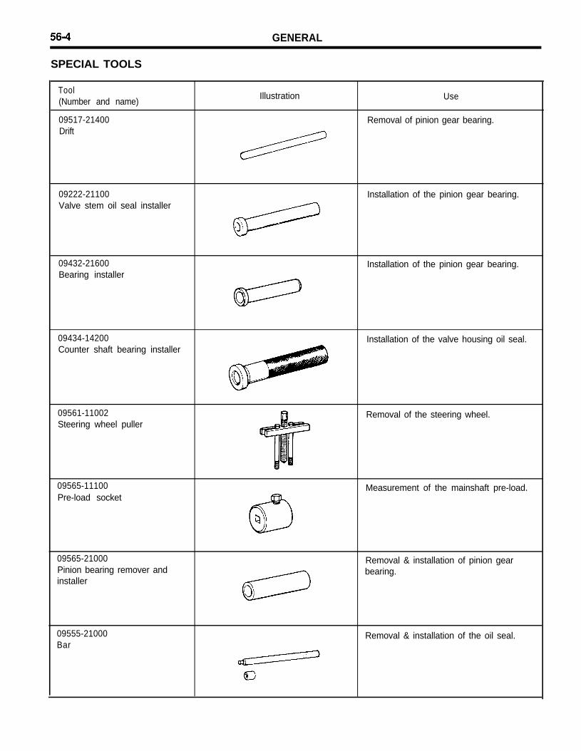
SPECIAL TOOLS
Tool(Number and name)
09517-21400Drift
Illustration Use
Removal of pinion gear bearing.
09222-21100Valve stem oil seal installer
Installation of the pinion gear bearing.
09432-21600Bearing installer
Installation of the pinion gear bearing.
09434-14200Counter shaft bearing installer
Installation of the valve housing oil seal.
09561-11002Steering wheel puller
Removal of the steering wheel.
09565-11100Pre-load socket
Measurement of the mainshaft pre-load.
09565-21000Pinion bearing remover andinstaller
Removal & installation of pinion gearbearing.
09555-21000Bar
Removal & installation of the oil seal.
GENERAL 56-5
56-6 GENERAL
TROUBLESHOOTING
Symptom
Excessive play ofsteering wheel
Steering wheel opera-tion is heavy (Insufficientpower assist)
The steering wheeldoes not returnproperly
Noise
Probable cause
Loose rack support cover
Loose steering gear mounting bolts
Loose or worn tie-rod end
V-belt slippage
Damaged V-belt
Low fluid level
Air in the fluid
Twisted or damaged hoses
Insufficient oil pump pressure
Sticky flow control valve
Excessive internal oil pump leakage
Excessive oil leaks from rack and pinionin gear box
Distorted or damaged gear box or valve bodyseal ring
Remedy
Retighten
Retighten
Retighten or replace as necessary
Check
Replace
Replenish
Bleed air
Correct the routing or replace
Repair or replace the oil pump
Replace
Replace damaged parts
Replace damaged parts
Replace
Excessive turning resistance of tie-rod end
Excessively tightened rack support cover
Rough turning or inner tie-rod and/or ball joint
Loose mounting of gear box to gear boxmounting bracket
Replace
Adjust
Replace
Retighten
Worn steering shaft joint and/or body grommet Correct or replace
Distorted rack Replace
Damaged pinion bearing Replace
Twisted or damaged hoses Reroute or replace
Damaged oil pressure control valve Replace
Damaged oil pump input shaft bearing Replace
Hissing Noise in Steering Gear
There is some noise in all power steering systems. One of the most common is a hissing soundwhen the steering wheel is turned and the car is not moving. This noise will be most evidentwhen turning the wheel while the brakes are applied.There is no relationship between this noise and steering performance. Do not replace the valveunless the “hissing” noise is extremely objectionable. A replacement valve will also have aslight noise, and is not always a cure for the condition.
GENERAL 56-7
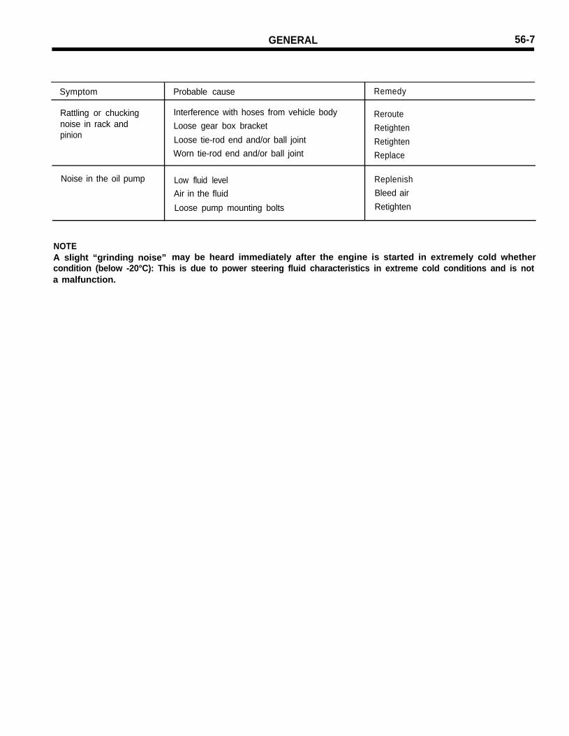
Symptom
Rattling or chuckingnoise in rack andpinion
Noise in the oil pump
Probable cause Remedy
Interference with hoses from vehicle body RerouteLoose gear box bracket RetightenLoose tie-rod end and/or ball joint RetightenWorn tie-rod end and/or ball joint Replace
Low fluid level Replenish
Air in the fluid Bleed air
Loose pump mounting bolts Retighten
NOTEA slight “grinding noise” may be heard immediately after the engine is started in extremely cold whethercondition (below -20°C): This is due to power steering fluid characteristics in extreme cold conditions and is nota malfunction.
56-6 GENERAL
SERVICE ADJUSTMENT PROCEDURE
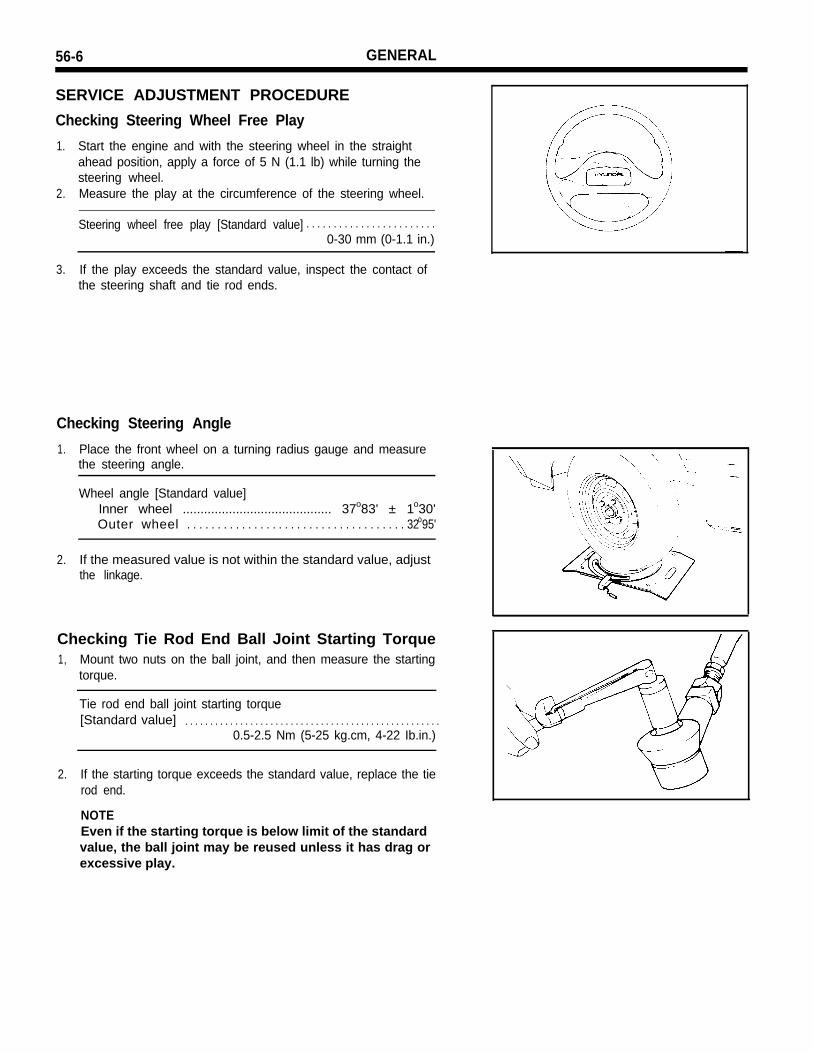
Checking Steering Wheel Free Play
1. Start the engine and with the steering wheel in the straightahead position, apply a force of 5 N (1.1 lb) while turning thesteering wheel.
2. Measure the play at the circumference of the steering wheel.
2. If the starting torque exceeds the standard value, replace the tierod end.
NOTEEven if the starting torque is below limit of the standardvalue, the ball joint may be reused unless it has drag orexcessive play.
GENERAL 56-9
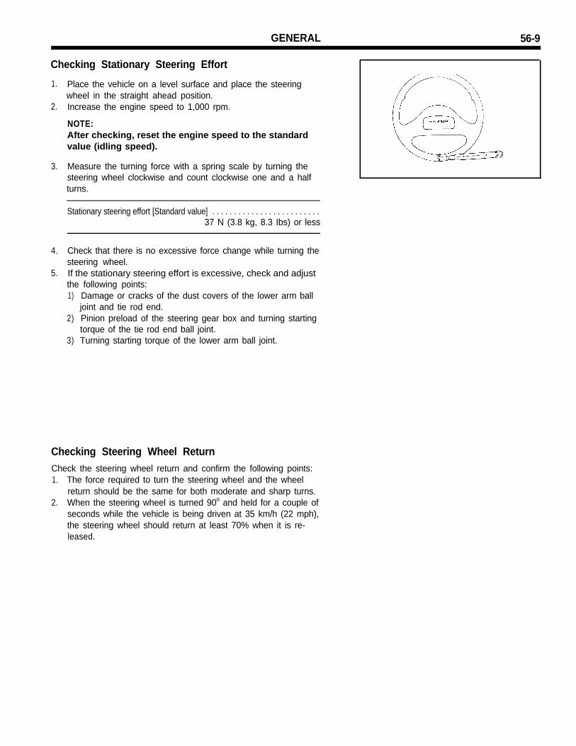
Checking Stationary Steering Effort
1.
2.
3.
Place the vehicle on a level surface and place the steeringwheel in the straight ahead position.Increase the engine speed to 1,000 rpm.
NOTE:After checking, reset the engine speed to the standardvalue (idling speed).
Measure the turning force with a spring scale by turning thesteering wheel clockwise and count clockwise one and a halfturns.
4.
5.
Check that there is no excessive force change while turning thesteering wheel.If the stationary steering effort is excessive, check and adjustthe following points:1) Damage or cracks of the dust covers of the lower arm ball
joint and tie rod end.2) Pinion preload of the steering gear box and turning starting
torque of the tie rod end ball joint.3) Turning starting torque of the lower arm ball joint.
Checking Steering Wheel ReturnCheck the steering wheel return and confirm the following points:1. The force required to turn the steering wheel and the wheel
return should be the same for both moderate and sharp turns.2. When the steering wheel is turned 90o and held for a couple of
seconds while the vehicle is being driven at 35 km/h (22 mph),the steering wheel should return at least 70% when it is re-leased.
Checking Power Steering Fluid Level1. Position the vehicle on a level surface.2. Start the engine. With the vehicle kept stationary, turn the
steering wheel several times continuously to raise the fluidtemperature from 50-60oC (122-140°F).
3. With the engine at idle, turn the steering wheel fully clockwiseand counterclockwise several times.
4. Make sure there is no foaming or cloudiness in the reservoirfluid.
5. Stop the engine to check for a difference in fluid level betweena stationary and a running engine.
NOTE1) If the fluid level varies 5 mm (0.2 in.) or more, bleed the
system again.2) If the fluid level suddenly rises after stopping the
engine, insufficient bleeding is indicated.3) Incomplete bleeding will produce a chattering sound in
the pump and a noise in the flow control valve, decreasing durability of the pump.
Replacing Power Steering Fluid
1.2.
3.
4.
5.
6.
Jack up the front of the car and support with rigid racks.Disconnect the return hose from the oil reservoir and plug theoil reservoir.Connect a hose to the disconnected return hose, and drain theoil into a container.Disconnect the high-tension cable at the ignition coil side.While operating the starter motor intermittently, turn the steer-ing wheel all the way to the left and then to the right severaltimes to drain the fluid.Connect the return hoses, then fill the oil reservoir with thespecified fluid.Bleed the system.Automatic transmission fluid DEXRON II type:Total quantity : Approx. 0.9 liter (0.95 qts.)
GENERAL 56-11
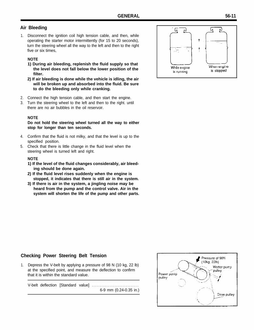
Air Bleeding
1. Disconnect the ignition coil high tension cable, and then, whileoperating the starter motor intermittently (for 15 to 20 seconds),turn the steering wheel all the way to the left and then to the rightfive or six times,
NOTE1) During air bleeding, replenish the fluid supply so that
the level does not fall below the lower position of thefilter.
2) If air bleeding is done while the vehicle is idling, the airwill be broken up and absorbed into the fluid. Be sureto do the bleeding only while cranking.
2. Connect the high tension cable, and then start the engine.3. Turn the steering wheel to the left and then to the right. until
there are no air bubbles in the oil reservoir.
NOTEDo not hold the steering wheel turned all the way to eitherstop for longer than ten seconds.
4. Confirm that the fluid is not milky, and that the level is up to thespecified position.
5. Check that there is little change in the fluid level when thesteering wheel is turned left and right.
NOTE1) If the level of the fluid changes considerably, air bleed-
ing should be done again.2) If the fluid level rises suddenly when the engine is
stopped, it indicates that there is still air in the system.3) If there is air in the system, a jingling noise may be
heard from the pump and the control valve. Air in thesystem will shorten the life of the pump and other parts.
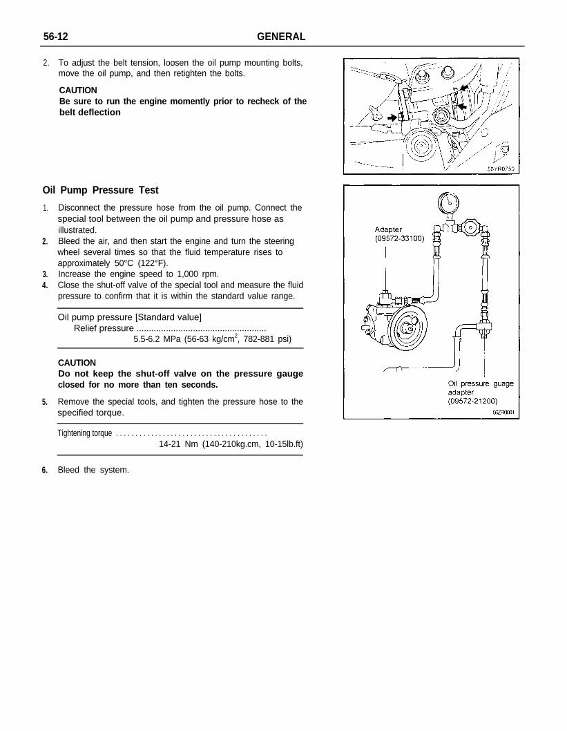
Checking Power Steering Belt Tension
1. Depress the V-belt by applying a pressure of 98 N (10 kg, 22 lb)at the specified point, and measure the deflection to confirmthat it is within the standard value.
2. To adjust the belt tension, loosen the oil pump mounting bolts,move the oil pump, and then retighten the bolts.
CAUTIONBe sure to run the engine momently prior to recheck of thebelt deflection
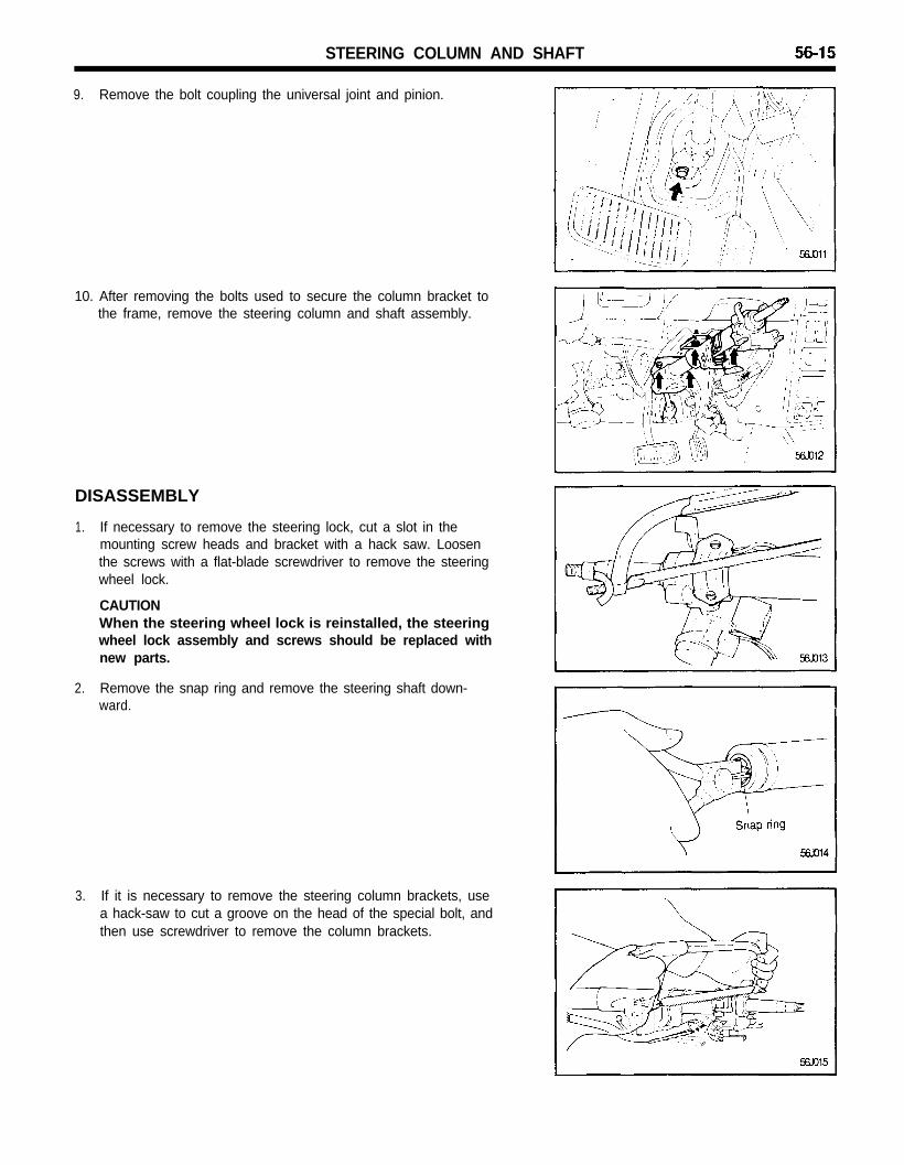
Oil Pump Pressure Test
1. Disconnect the pressure hose from the oil pump. Connect thespecial tool between the oil pump and pressure hose asillustrated.
2.
3.4.
Bleed the air, and then start the engine and turn the steeringwheel several times so that the fluid temperature rises toapproximately 50°C (122°F).Increase the engine speed to 1,000 rpm.Close the shut-off valve of the special tool and measure the fluidpressure to confirm that it is within the standard value range.
1. Remove the horn cover assembly.2. Remove the upper and lower horn plate, and disconnect the
horn button connector.
CAUTIONBefore doing these procedures, see the SRS section (56AGROUP) for further information (SRS equipped vehicleonly).
3. Remove the steering wheel lock nut.4. After making alignment marks on the steering shaft and wheel,
remove the steering wheel, using the special tool.
NOTEDo not hammer on the steering wheel to remove it: doingso may damage the steering column.
5. Remove the lower crash pad, and disconnect the rheostatconnector.
6. Remove the column shroud.
7. Disconnect the connectors.
8. Remove the multifunction switch.
STEERING COLUMN AND SHAFT
9. Remove the bolt coupling the universal joint and pinion.
10. After removing the bolts used to secure the column bracket tothe frame, remove the steering column and shaft assembly.
DISASSEMBLY
1. If necessary to remove the steering lock, cut a slot in themounting screw heads and bracket with a hack saw. Loosenthe screws with a flat-blade screwdriver to remove the steeringwheel lock.
CAUTIONWhen the steering wheel lock is reinstalled, the steeringwheel lock assembly and screws should be replaced withnew parts.
2. Remove the snap ring and remove the steering shaft down-ward.
3. If it is necessary to remove the steering column brackets, usea hack-saw to cut a groove on the head of the special bolt, andthen use screwdriver to remove the column brackets.
56-16 STEERING COLUMN AND SHAFT
4. Remove the snap ring then tap out the clevis pin from the innerside. (Tilt steering only)
5. If necessary, remove the tilt steering lever and mountingbracket. (Tilt steering only)
INSPECTION
1. Check the steering column and shaft for damage and distortion.2. Check the joints for play, damage or rough movement.3. Check the tilt bracket and spring for cracks and damage.4. Check that the steering lock mechanism operates properly.5. Check the dust cover for cracks or damage.
If necessary, replace.
ASSEMBLY
1. When installing the steering column brackets, tighten thespecial bolt until the head twists off.
CAUTIONA new special screw must be used each time.
INSTALLATION
1. When installing the steering lock and steering lock bracket tothe column tube, temporarily install the steering lock in alignment with the column boss.
2. After checking the lock works properly, tighten the special boltsuntil the head twists off.
CAUTIONThe steering lock bracket and bolts must be replaced withnew ones when the steering lock is installed.
STEERING COLUMN AND SHAFT 56-17
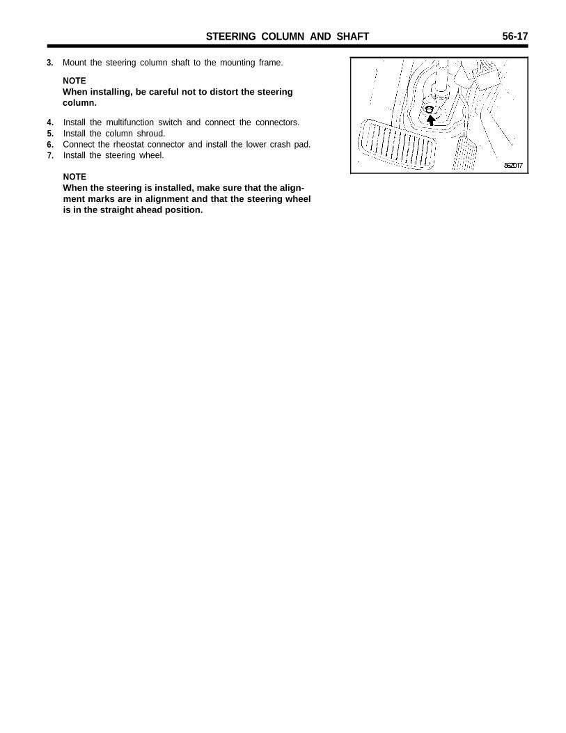
3. Mount the steering column shaft to the mounting frame.
NOTEWhen installing, be careful not to distort the steeringcolumn.
4.5.6.7.
Install the multifunction switch and connect the connectors.Install the column shroud.Connect the rheostat connector and install the lower crash pad.Install the steering wheel.
NOTEWhen the steering is installed, make sure that the align-ment marks are in alignment and that the steering wheelis in the straight ahead position.
56-18 POWER STEERING GEAR BOX
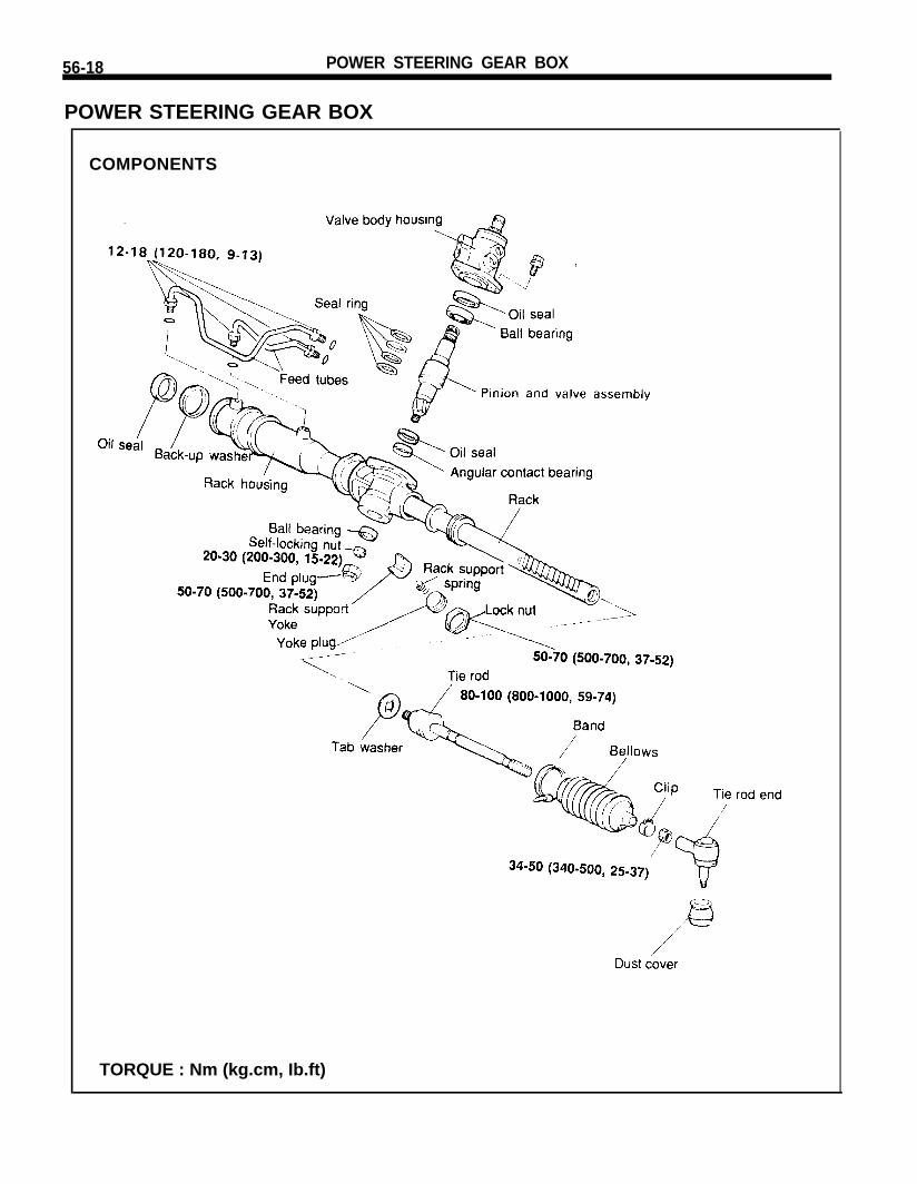
POWER STEERING GEAR BOX
COMPONENTS
TORQUE : Nm (kg.cm, Ib.ft)
POWER STEERING GEAR BOX 56-19
REMOVAL
1. Using special tool, disconnect the tie rod end from the knuckle.
2. Disconnect the shaft assembly from the gear box inside thedriver’s seat compartment.
3. Drain the fluid.4. Disconnect the pressure and return hoses from the gear box.5. Remove the band from the steering joint cover.
6. Remove the gear box mounting bolts.7. Pull the gear box out toward the right side of the vehicle.
NOTEWhen the gear box is to be removed, pull it out carefullyand slowly so as not to cause damage to the boots.
INSPECTION AND ADJUSTMENT PRIORTO DISASSEMBLY
Mount the gear box in a soft jawed vise.
NOTEDo not tighten the vise on the gear housing. Use the mountingsection of the rack to secure it in the vise.
56-20 POWER STEERING GEAR BOX
Total Pinion Preload1. Rotate the pinion gear for approximately 4 to 6 seconds for one
3. If the measured value exceeds the standard value, replace thetie rod assembly.
NOTEEven if the measured value is below the standard value, atie rod that swings smoothly without excessive play maybe used. If the measured value is below 4.3 N (0.9 lb)[100Ncm (8.7 Ib.in.)], replace the tie rod.
Bellows Inspection
1. Inspect the bellows for damage or deterioration.2. Make sure the bellows are secured in the correct position3. If the bellows are defective, replace them.
POWER STEERING GEAR BOX 56-21
DISASSEMBLY
1. Remove the tie rod end from the tie rod.
2. Remove the dust cover from the ball joint.
3. Remove the bellows band.
4. Remove the bellows clip.5. Pull the bellows out toward the tie rod.
NOTECheck for rust on the rack when the bellows are replaced.
6. Remove the feed tube from the gear housing.7. While moving the rack slowly, drain the fluid from the gear
housing.
8. Remove the end plug.9. With the pinion turned clockwise until the rack is locked, remove
the self-locking nut.
POWER STEERING GEAR BOX
10. Unstake the tab washer between the tie rod and rack with achisel.
11. Remove the tie rod from the rack.
NOTERemove the tie rod from the rack, taking care not to twistthe rack.
12. Remove the yoke plug locking nut
13. Using special tool, remove the yoke plug.
14. Remove the rack support spring, rack support yoke from thegear box.
POWER STEERING GEAR BOX
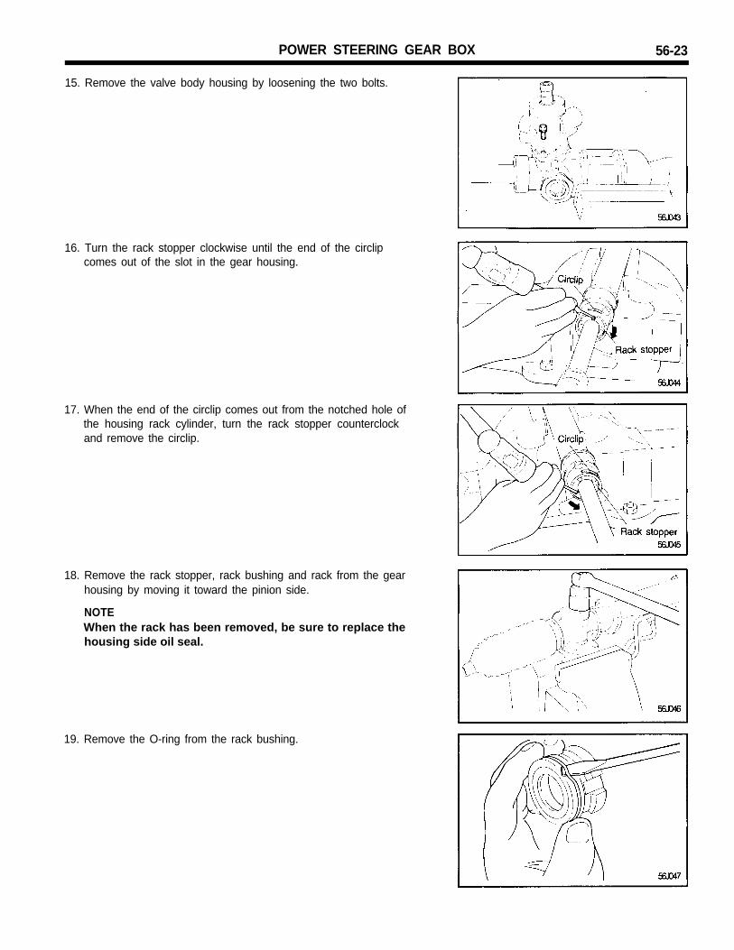
15. Remove the valve body housing by loosening the two bolts.
56-23
16. Turn the rack stopper clockwise until the end of the circlipcomes out of the slot in the gear housing.
17. When the end of the circlip comes out from the notched hole ofthe housing rack cylinder, turn the rack stopper counterclockand remove the circlip.
18. Remove the rack stopper, rack bushing and rack from the gearhousing by moving it toward the pinion side.
NOTEWhen the rack has been removed, be sure to replace thehousing side oil seal.
19. Remove the O-ring from the rack bushing.
56-24 POWER STEERING GEAR BOX
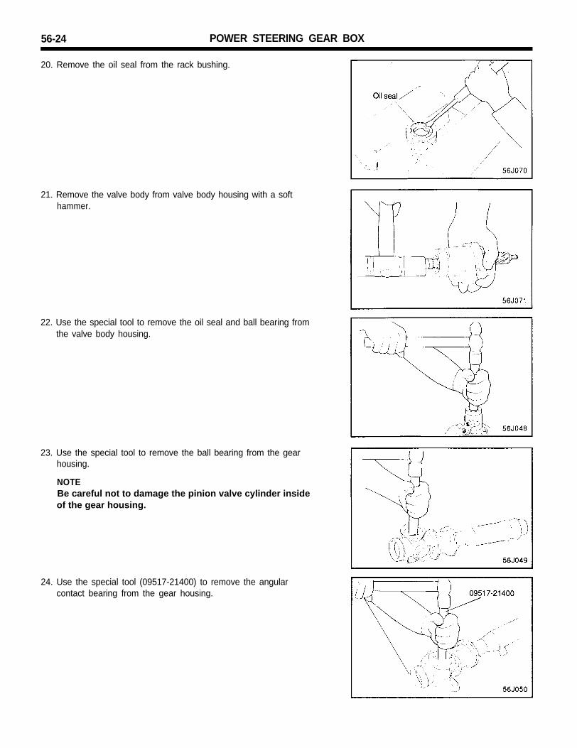
20. Remove the oil seal from the rack bushing.
21. Remove the valve body from valve body housing with a softhammer.
22. Use the special tool to remove the oil seal and ball bearing fromthe valve body housing.
23. Use the special tool to remove the ball bearing from the gearhousing.
NOTEBe careful not to damage the pinion valve cylinder insideof the gear housing.
24. Use the special tool (09517-21400) to remove the angularcontact bearing from the gear housing.
POWER STEERING GEAR BOX 56-25
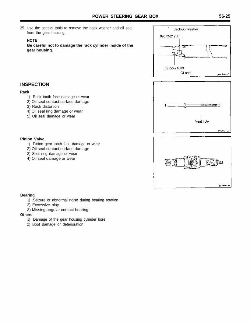
25. Use the special tools to remove the back washer and oil sealfrom the gear housing.
NOTEBe careful not to damage the rack cylinder inside of thegear housing.
INSPECTION
Rack1) Rack tooth face damage or wear2) Oil seal contact surface damage3) Rack distortion4) Oil seal ring damage or wear5) Oil seal damage or wear
Pinion Valve1) Pinion gear tooth face damage or wear2) Oil seal contact surface damage3) Seal ring damage or wear4) Oil seal damage or wear
Bearing1) Seizure or abnormal noise during bearing rotation2) Excessive play.3) Missing angular contact bearing.
Others1) Damage of the gear housing cylinder bore2) Boot damage or deterioration
56-26 POWER STEERING GEAR BOX
ASSEMBLY
1. Apply the specified oil to the entire surface of the rack oil seal.
Set the scribed side of the angular contact bearing the specialtool and install it into the gear housing (until the special toolcontacts the gear housing).
NOTENote the direction of the angular contact bearing.
Apply the specified grease to the ball bearing and install usingthe special tool.
NOTEDo not plug the vent hole in the rack with grease.
10. Wrap the rack end with vinyl tape, apply a coating of thespecified fluid, and then install the rack bushing and rackstopper.
NOTEDo not allow oil seal retainer spring to slip out.
11. Push in the rack stopper until the circlip groove of the rackstopper is aligned with the notched hole of the rack housing.Install the circlip while turning the rack stopper.
NOTEThe circlip end should not be visible through the notchedhole of the rack housing.
12. Using special tool, install the oil seal and the ball bearing in thevalve body.
13. When installing seal rings, press firmly into valve groove.Apply specified fluid.
56-28 POWER STEERING GEAR BOX
14. Apply the specified oil and grease to the pinion valve assemblyand install in the gear housing assembly.
20. Stake the end plug at two points on its circumference with apunch.
21. Install the rack support yoke, rack support spring and yoke plugin the order shown. Apply semi-drying sealant to the threadedsection of the yoke plug before installation.
22. With the rack placed in the center position, attach the racksupport cover to the gear housing. Tighten the rack supportcover to 15 Nm (150 kg.cm, 11 Ib.ft), using the special tool.Loosen the yoke plug approximately 30 to 60o, and tighten thelocking nut to the specified torque.
NOTEWhen the bellows are installed, a new band must be used.
26. Install the bellows in position, taking care not to twist it.
27. Fill the dust cover inner side and lip with the specified multi-purpose grease, and place the dust cover in position with theclip ring attached in the groove of the tie rod end.
56-30 POWER STEERING GEAR BOX
INSTALLATION
1. Screw in tie rod end to have its right and left length as illustrated.Lock with lock nut.
POWER STEERING OIL PUMP 56-31
POWER STEERING OIL PUMP
COMPONENTS
TORQUE : Nm (kg.cm, Ib.ft)
REMOVAL
CAUTIONBe sure to cover the generator with a protector when servicingthe oil pump.
1. Remove the pressure hose from the oil pump.2. Disconnect the suction hose from the suction connector and
drain the fluid into a container.
POWER STEERING OIL PUMP
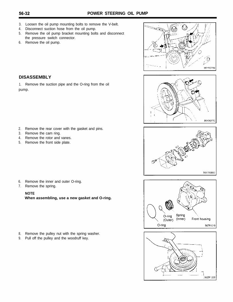
3. Loosen the oil pump mounting bolts to remove the V-belt.4. Disconnect suction hose from the oil pump.5. Remove the oil pump bracket mounting bolts and disconnect
the pressure switch connector.6. Remove the oil pump.
DISASSEMBLY
1. Remove the suction pipe and the O-ring from the oilpump.
2. Remove the rear cover with the gasket and pins.3. Remove the cam ring.4. Remove the rotor and vanes.5. Remove the front side plate.
6. Remove the inner and outer O-ring.7. Remove the spring.
NOTEWhen assembling, use a new gasket and O-ring.
8. Remove the pulley nut with the spring washer.9. Pull off the pulley and the woodruff key.
POWER STEERING OIL PUMP 56-33
10. Remove the snap ring using snap ring pliers.11. Drive out the pulley shaft with the bearing.
If necessary, use plastic hammer.
12. Remove the oil seal from the oil pump body.
NOTEWhen assembling, use a new oil seal.
13. Remove the guide bracket and nut.14. Remove the connector from the oil pump body, and take out the
flow control valve and the flow control spring.15. Remove the O-ring from the connector.
CAUTIONDo not disassemble the flow control valve.
16. Remove the oil pump switch.17. Take out the spring and the spool.18. Remove the O-ring from the oil pump switch
INSPECTION
1. Clean all disassembled parts with suitable cleaning solvent.2. If any inside parts of the oil pump have been damaged, replace
the pump as an assembly.3. If the pulley is cracked or deformed, replace it.4. If oil leaks from around pulley shaft oil seal, replace the oil seal.5. If the serrations of the pulley or pulley shaft are deformed or
worn, replace them.
56-34 POWER STEERING OIL PUMP
ASSEMBLY
1. Install the oil pump switch.2. Install the flow control valve spring, valve and connector in the
pump body.
NOTEApply a thin coat of A.T.F. to all the replaced parts includ-ing the oil seal and the O-ring.
3. Install the guide bracket and nut.
4. Using special tool, install the oil seal into the pump body.
5. Gently insert the shaft assembly and install the snap ring.6. Install the pump pulley with woodruff key in place.
7. Install the spring and the inner and outer O-rings.8. Install the front side plate.
9. Insert the pins into the pin grooves of front housing, then installthe cam ring, paying attention to its direction.
POWER STEERING OIL PUMP
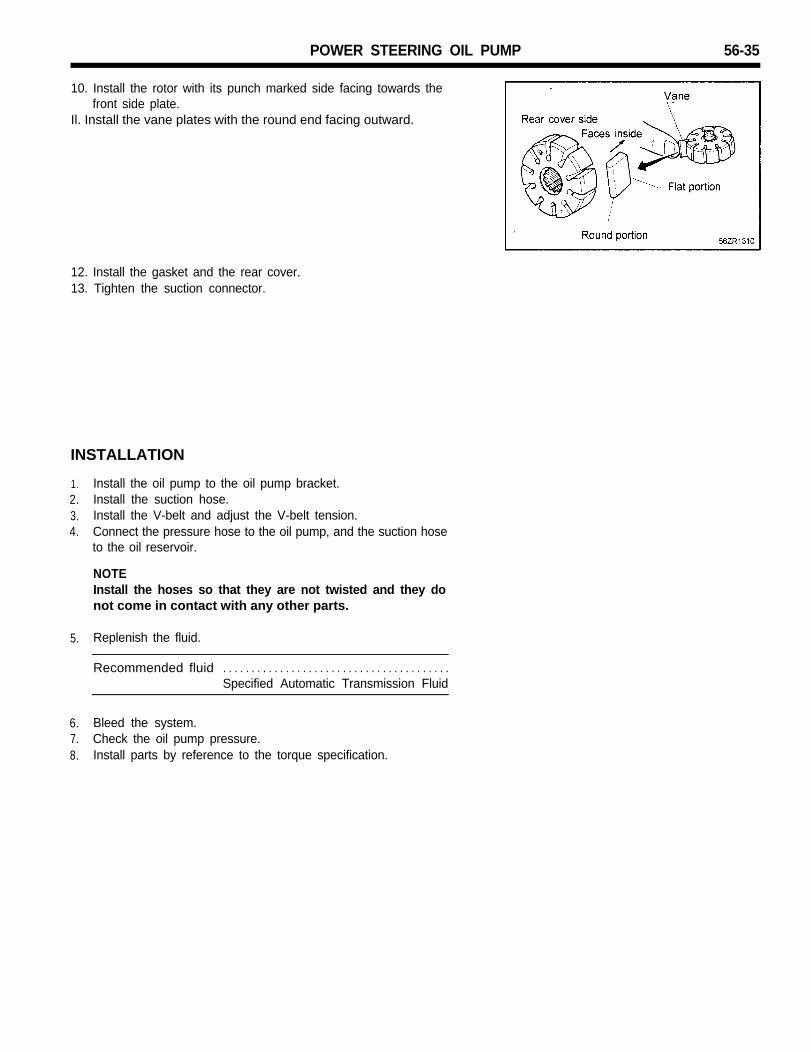
10. Install the rotor with its punch marked side facing towards thefront side plate.
56-35
Il. Install the vane plates with the round end facing outward.
12. Install the gasket and the rear cover.13. Tighten the suction connector.
INSTALLATION
1.2.3.4.
Install the oil pump to the oil pump bracket.Install the suction hose.Install the V-belt and adjust the V-belt tension.Connect the pressure hose to the oil pump, and the suction hoseto the oil reservoir.
NOTEInstall the hoses so that they are not twisted and they donot come in contact with any other parts.
Bleed the system.Check the oil pump pressure.Install parts by reference to the torque specification.
56-36 POWER STEERING HOSES
POWER STEERING HOSES
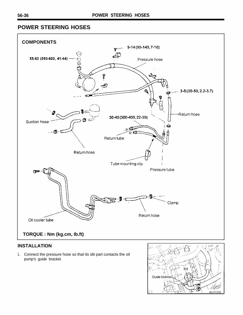
COMPONENTS
TORQUE : Nm (kg.cm, Ib.ft)
INSTALLATION
1. Connect the pressure hose so that its slit part contacts the oilpump’s guide bracket.
POWER STEERING HOSES 56-37
2. When the pressure hose is installed, align the white line on thepressure hose with the white line on the pressure tube so thattogether they form a straight line.