+ All Categories
Home > Documents > Step by Step of Radiographic Processing · Step by Step of Radiographic Processing ... (QAP) in...

Step by Step of Radiographic Processing · Step by Step of Radiographic Processing ... (QAP) in...

Date post: 29-May-2018
Category:
Upload: vonhu
View: 219 times
Download: 0 times
Share this document with a friend
35
Step by Step of Radiographic Processing (A good practice´s manual) Ana Cecília Pedrosa de Azevedo Sergio Ricardo de Oliveira Centro de Estudos da Saúde do Trabalhador e Ecologia Humana — CESTEH Rio de Janeiro 2005
Transcript

Step by Step of Radiographic

Processing

(A good practice´s manual)

Ana Cecília Pedrosa de Azevedo

Sergio Ricardo de Oliveira

Centro de Estudos da Saúde do Trabalhador e Ecologia Humana — CESTEH

Rio de Janeiro 2005

2

INTRODUCTION

In Brazil, it was published in 1998, the Norm “Portaria 453/98” by

the Minister of Health, establishing the “Directives of Radioprotection in

Medical and Odontological Radiodiagnosis”. Since then, all medical institution

that makes use of ionizing radiation as a diagnostic method, must follow the

requirements contained in that norm.

Besides this, other two laws have been published, one giving

orientations with respect to architectural projects of medical installations (RDC

50/02) and another with respect to the appropriate disposal of chemical

products from radiology departments (RDC 306/04).

One of the main requirements of the Portaria 453/98 is the need

of the implementation of Quality Assurance Programs (QAP) in medical and

odontological radiodiagnosis departments. The QAP have as main objective to

guarantee the production of a high quality image, imparting the lowest possible

dose to the patient and at a reduced cost. The Quality Control (QC) of

processing systems is one of the most important aspects in the implementation

of these Programs.

There are three main steps to generate a radiographic image:

formation of the latent image, film processsing and image visualization. All these

steps are of equal importance since they interfere in the final image quality,

allowing the production of a good radiograph that will contain all the anatomical

details necessary to the elaboration of a correct diagnosis report.

The objective of this manual is to provide basic instructions and

hints about good practices in radiographic processing. The manual includes

considerations about the dark room, the automatic processor and the chemical

products as well as its accessories (cassettes, screens and films). It presents

3

also an orientation on how to implement the sensitometric control of the

automatic processors used in radiology departments.

One of the main requirements for a good processing is that in the

department the processors, films, chemical products and accessories are all

from the same manufacturer, the so-called “crossed system”. This requirement

is essencial for the production of a high quality image. If this requirement is not

obeyed, the image can be degraded and the dose imparted to the patient,

become inadequate.

Another important aspect concerns the cleaning conditions of the

dark room, the processor and its accessories. Lack of cleaning ness and the

presence of dust can cause artifacts in the radiographic image that can hide

important radiological signs, necessary to a correct diagnosis.

4

SUMMARY

1 DARK ROOM...................................................................5

1.1 ENVIRONMENTAL CONDITIONS...............................................................................................................5

1.2 LIGHT TIGHT TEST.........................................................................................................................................7

1.3 SAFE LIGHTS.....................................................................................................................................................8

1.4 FOG TEST............................................................................................................................................................9

1.5 CLEANING.........................................................................................................................................................11

2 AUTOMATIC PROCESSOR................................................... 13

2.1 TRANSPORT SPEED ......................................................................................................................................14

2.2 REPLENISHMENT RATE ..............................................................................................................................14

2.3 CLEANING AND PERIODICAL MAINTENANCE...................................................................................15

3 CHEMICAL PRODUCTS ...................................................... 16

3.1 CHEMICAL PRODUCTS PREPARATION...................................................................................................16

3.2 CHEMICAL EFFLUENTS...............................................................................................................................19

4 ACESSORIES................................................................ 20

4.1 FILMS................................................................................................................................................................20

4.2 SCREENS ..........................................................................................................................................................22

5 ARTIFACTS ................................................................. 24

6 VIEWING BOXES ........................................................... 26

7 SENSITOMETRY ............................................................ 27

8 REFERENCES ................................................................ 32

9 CHECK LIST................................................................. 34

5

1 Dark room

The dark room is the location where the radiographic films are processed.

According to Brazilian legislation the room (RDC 50/04) this room must have

adequate dimensions with respect to the number of processed films and the

quantity of technicians who work in the department. Inside the dark room there

must be only: the automatic processor (or the tanks with chemicals is case of

manual processing), a box to keep the unprocessed (virgin) films, the safe light

and the cassettes.

1.1 Environmental conditions

• The ambient temperature inside the dark room must be kept from 10ºC

to 21ºC.

• The relative humidity must be around 30% to 50%.

• The ventilation should be evaluated by properly trained personnel who

will guarantee that there are, at least, 10 complete changes of air per

hour.

• The exhausting system is of major importance e and should be

designed according to the dark room dimensions. The exhauster should

be preferably directly connected to the processor exit.

• The dark room walls should of light color and recovered with mat

material (preferably) easy to clean and resistant to the chemical

reactions of the chemical products used in the processor as well as to

the cleaning meterials.

• The ceiling must be solid in order to avoid dust falling as well as

humidity from coming from the upper pavement (if applicable).

6

• The use of open shelters in not recommended due to the possibility of

dust accumulation. Instead, it is recommended the use of furniture

with doors, preferably located on the lower side of the working table.

• Safe light(s) must be installed inside the dark room according to the

recommendations of part 1.3 of this manual. The safe light(s) must

provide an appropriate luminance level to allow the staff to work inside

it and at the same time not fogging the films.

• The interior of the ark room must be free of any objects other than

those absolutely necessary to the processing procedures, such as

chemical products, boxes, clothes, radios, etc…

Figure 1 – Interior of a dark room in good conditions

7

1.2 Light tight test

The importance of light tighthness is fog reduction. To check light

tightness follow the steps below:

• Turn on all light of rooms adjacent to the dark room;

• Go inside the dark room and turn off all sources of light inside it,

includind the safe light;

• Stay inside the dark room for at least 10 minutes (period of time

necessary to visual accommodation);

• Mark all locations where you can see external light, so that they can be

repaired.

After repairing the eventual light leaks the luminance level must be

checked. This measurement is performed with a photometer (or luximeter) as

seen in figure 1. The measured value must be at maximum 2 lux, with the safe

light turned off and of 10 lux under normal working conditions (safe light turned

on).

Figure 2 – Photometer

8

1.3 Safe lights

One or more safe lights are installed inside the dark room to allow a

proper illuminance level so that the operator can see inside it without fogging

the films. The safe light is composed of a metal box, a white bulb and a filter.

The maximum bulb power should be 15 watts. The distance between the safe

light and the manipulation/working surface should be, at least, 120 cm. The

filter is the most important part of the safe light and must be suitable to the

type of radiographic film used in the department. The most common type used

with ortochromatic films (green base) is the red filter. Special attention must

be given when installing the filter since it has a gel on one side and this side

must be installed facing the external part not in the bulb direction. The

installation date must be registered. It is important to check with the

manufacturer the replacement recommendations and the useful life. In general,

for a safe light that is on during 10 hours a day, the filter durability is around 4

months. If the safe light is appropriate, the radiographic films will not fog.

Figure 3 – Safe light and filter

9

1.4 Fog test

The fog in the radiographic film can have several origins:

• Ionizing radiation;

• “Safe” lights, that do not follow the above mentioned

recommendations;

• “Unsafe lights”, that can be: light leakage entering the dark room,

generally around the doors, the processor and the film bins, defective

cassettes, luminous dials and perforations in the ceiling, among others.

The fog test checks if there are light leakages that can be fogging the

film. High levels of fog can cause loss of contrast in the radiographic image and

degrade image quality.

The most effective test to evaluate fog level in the dark rooms is to

expose the radiographic film to a sensitometer light. A sensitometer is an

equipment that emits light with the same characteristics of the light coming

from the screens. Therefore, it serves to simulate an exposure to the X rays.

The film exposure must be performed in four steps according to figure 5, in

such a way that the strips be uncovered, one by one, and being exposed to time

of 4, 2, 1 and 0 minutes after exposure respectively. After this procedure,

process the film normally and compare the results of the film darkness (optical

Density) of each strip. The results obtained will be compared with the

“standard” or “reference” film that was obtained before exposing the film to

the sensitometer light, however, with all safe light(s) turned off.

The film darkness is measured using a densitometer (equipment that

evaluates the optical density-OD). The results must show that the difference

between the standard and the real film, obtained at times 0, 1, 2 and 4 minutes,

must be at most 0,05.

10

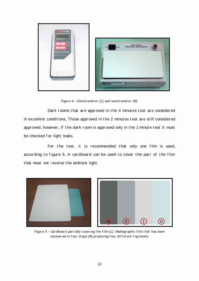
Figure 4 – Densitometer (L) and sensitometer (R).

Dark rooms that are approved in the 4 minutes test are considered

in excellent conditions, Those approved in the 2 minutes test are still considered

approved, however, if the dark room is approved only in the 1 minute test it must

be checked for light leaks.

For the test, it is recommended that only one film is used,

according to figure 5. A cardboard can be used to cover the part of the film

that must not receive the ambient light.

Figure 5 – Cardboard partially covering the film (L). Radiographic film that has been

uncovered in four steps (R) producing four different fog levels.

11

1.5 Cleaning

Cleaning is of major importance since dust and grease may cause

artifacts. Cleaning must be performed daily and include all surfaces: floor, table

top, film bins, and especially the processor entrance tray. A moisturized soft

cloth must be used. Vacuum first, if necessary. Clean the entrance processor

tray at last.

When mammographic films are handled, the cleaning procedures

must be performed twice a day.

Clean regularly the air conditioning filter as well as the exit of the

exhausting air exit (if it is not directly connected to the processor exit).

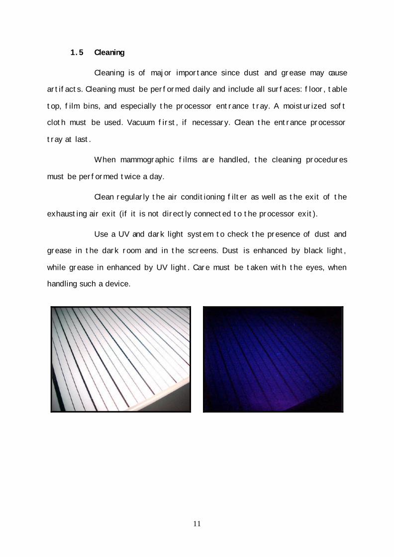
Use a UV and dark light system to check the presence of dust and

grease in the dark room and in the screens. Dust is enhanced by black light,

while grease in enhanced by UV light. Care must be taken with the eyes, when

handling such a device.

12

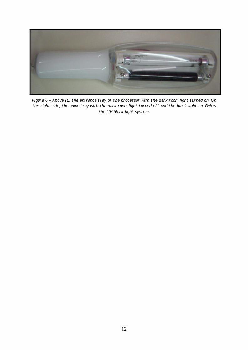
Figure 6 – Above (L) the entrance tray of the processor with the dark room light turned on. On the right side, the same tray with the dark room light turned off and the black light on. Below

the UV black light system.

13

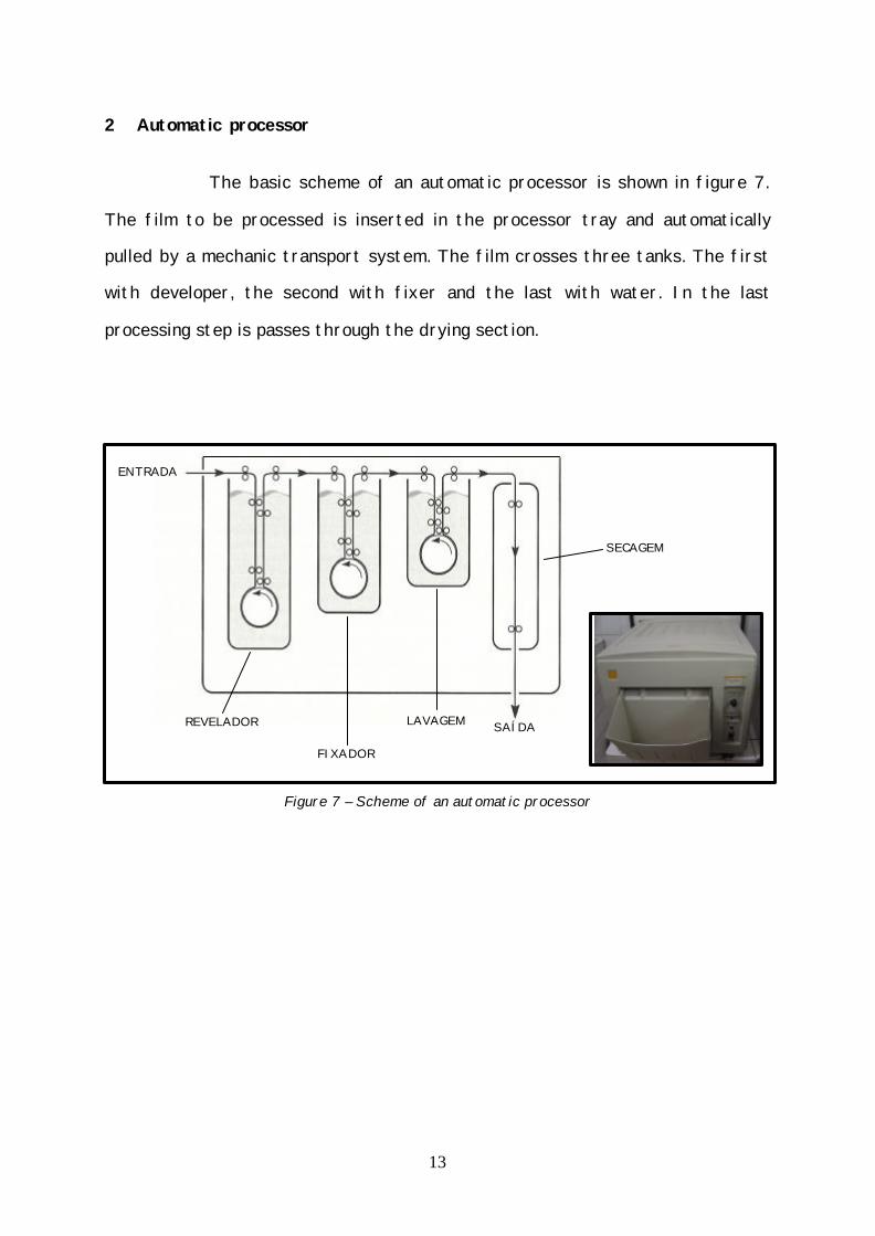
2 Automatic processor

The basic scheme of an automatic processor is shown in figure 7.

The film to be processed is inserted in the processor tray and automatically

pulled by a mechanic transport system. The film crosses three tanks. The first

with developer, the second with fixer and the last with water. In the last

processing step is passes through the drying section.

Figure 7 – Scheme of an automatic processor

ENTRADA

SAÍDA REVELADOR

FIXADOR

LAVAGEM

SECAGEM

14

2.1 Transport speed

Transport speed is defined as the time necessary to a radiographic

film to pass through each section of the processing cycle. (developing, fixing,

washing and drying). The dry-to-dry time is the total time that the film takes to

be completely processed.

These times are measured with a chronometer and shouldn´t vary

more than 3% with respect to manufactures´recommendation. In conventional

radiology, the dry-to-dry processing time is 90 seconds and in mammography

(extended cycle) it ranges from 120-150 seconds.

2.2 Replenishment rate

Replenishmnent rate is defined as the amount of developer and

fixer that are introduced in the processor tanks when a film is inserted in the

processor tray. It must be completely defined in terms of film length, number

of films and area of the film to be processed. The system consists of a timer

that is coupled to the processor and is periodically activated. Ex.: during 20

seconds at each 5 minutes, introducing 65 ml of developer in the tank.

When the processor develops a reduced number of films per day,

flooded replenishment is recommended to keep the activity of the chemical

products. The automatic processor has also a system of re-circulation pumps to

keep the chemicals homogeneous and at Constant temperature.

The replenishment rate ranges from 60 to 600ml/min for the

developer and from 80 to 800ml/h for the fixer. Attention to the difference in

units: for the developer it is per minute whilst for the fixer it is per hour.

Therefore it is clear that the quantity of developer is much bigger than the

fixer.

15

2.3 Cleaning and periodical maintenance

One of the main factors that affect the processing performance is

to keep an excellent cleaning standard and periodical maintenance. The cross

over rolls must be cleaned daily. The upper cover must be kept open overnight to

avoid water condensation and consequently the dilution of the chemicals.

Figure 8 – Cleaning the cross over rolls (L), keeping the upper cover open overnight (R).

Some situations contribute to cause problems in film processing.

They are:

• Reduced number of films to be processed (< 30/day)

• Films of different manufacturers/types

• Chemical products from different manufacturers.

• Films are not processed every day.

• Inconstant number of films processed per day.

The problems are generally caused in this order: developer, fixer,

drying, cross over rolls, cross over system, film transport system, chemical

products replenishment system and re-circulation system.

16

3 Chemical products

The main chemical products used in radiographic processing are the

developer and the fixer. Both are a mix of chemical elements that can be toxic,

carcinogenic and irritating. Therefore, during its preparation it is necessary the

use of appropriate Individual Protective Clothes, such as: gloves, aprons, glasses

and masks. It is important to stress that no chemical products should be kept

inside the dark room.

Figure 9 – Individual Protective Clothes – apron (L), glasses (C) e gloves (R).

The correct preparation of the chemical products, the processors

maintenance as well as the film keeping, must be performed according to the

manufacturer’s recommendations. However, the most usual procedures are:

3.1 Chemical products preparation

The developer and the fixer can be stored for up to two years (if

not prepared), if the ambient temperature is maintained around 21ºC. In the

case of prepared (diluted) products and temperature from 5-30ºC, they can be

17

kept for up to fifteen days, when no floating lid is used and up to six weeks if a

floating lid is used. The use of the floating lid reduces evaporation and avoids

contact of the developer with air reducing its oxidation and increasing its useful

life.

Figure 10 – Floating lid

Another very important component of the processing system is the

water used in the dilution of the chemical products and to wash the films. The

water must be filtered and the filter must be replaced periodically (generally

each 3 months). A 50 µm filter is the most appropriate. The water flux must be

kept from 0.95 to 5.7 l/min.

18

Figure 11 – Water filtering system

The water temperature must be from 4.5°C to 29.5°C or up to the

same temperature of the developer. Extreme temperatures can cause problems

in the fixing and washing besides being the cause of artifacts.

The ideal developer temperature depends on the kind of film, the

processing cycle as well as on the manufacturer´s recommendations. Generally,

it ranges from 33.5 to 38.3ºC. The temperature influences directly in the film

speed, in the patient exposure and in the radiographic contrast. Consequently, it

is of major importance that to adhere to manufacturer´s recommendations

keeping the developer temperature within the recommended limits of ±0.3°C.

The developer temperature must be checked daily with a

thermometer placed always in the same location of the tank. Avoid to use

mercury thermometers, prefer to use digital. The water used in the dilution of

the developer must be filtered using a 75 µm filter.

Concerning the fixer temperature it is not so crucial and can range

from 29.4°C to 35°C. There is no need to filter the water used for its

preparation. On the other hand, the drying temperature must never exceed the

manufacturer´s recommendations (generally from 37.8 and 71.2oC), otherwise

artifacts can appear.

19

3.2 Chemical effluents

The chemical effluents (developer and fixer) are substances that

can cause harm to human beings as well as to the natural environment. The

developer, after a neutralization process to maintain its pH between 7 and 9, can

be discarded in sewer system.

The fixer, can undergo a silver recovery process and be afterwards

taken to an appropriate treatment station.

20

4 Acessories

4.1 Films

The basic structure of a radiographic film can be seen in figures 12

and 13 below. The radiographic film is composed of a base that serves to give

support to the emulsion that will be sensitized and a protective layer. It is

important to stress that the mammographic film has single emulsion while the

radiographic film has double emulsion. The mammographic film presents a mark

in its border to assign the side that contains the emulsion.

Figure 12 – Scheme of a mammographic film

The base must have good stability, adequate water absorption and

be sufficiently transparent. The blue color is used to reduce the radiologist eye

fatigue. The latent radiographic image will be formed in the emulsion and

through the process of development the final image will be formed.

180 µm

10 µm

1 µm Prot. layer

Emulsion

Base

21

Figure 13 – Scheme of conventional radiology film.

The unexposed films must be kept in a place with temperature

between 10 and 21ºC, relative humidity between 30 and 50%, and far from

chemical vapors and heat. It is also necessary that the films be kept in the

vertical position using first the oldest ones.

After processing, the films must be kept at temperatures around

21ºC and relative humidity between 40 and 60%. If these recommendations are

not observed artifacts and film cracking may occur.

To check the efficiency of the washing process, it is recommended

that the fixer retention test be performed. This procedure must be done each

six months, according the procedure described in the following.

Ø Fixer retention test

The fixer retention test is employed to check the amount of

ammonia tiosulfate (hypo) that remained in the processed film. High quantities

of this compound indicate that the film has not been properly washed and that

after some time will present a yellowish appearance in the radiographs. This will

impair image quality. The maximum acceptable hypo limit is 0.02g/m2. This test

180 µm

a

250 µm

˜15 µm

˜1 µm Protect. layer

Emulsion

Base

˜1 µm

˜15 µm

22

is particularly important in mammography since the mammograms are kept for

long periods for comparison purposes. The test consists in dropping a small

amount of hypo in the processed film and comparing the obtained color with a

commercially available standard.

4.2 Screens

The modern radiographic screens are made of rare earth chemical

compounds. These compounds have the property of emiting light when excited by

X rays. Therefore, they are used, in diagnostic radiology, with the aim of

intensifying the film blackening allowing a reduction of patient exposure.

The cleaning of the screens is of major importance to increase its

useful life and allowing to obtain higher quality images. To perform the cleaning,

use preferably special chemical products. However, if they are not available, use

a baby shampoo or neutral soap diluted in water. Check with the manufacturer

about the possibility of using 70 % isopropyl alcohol.

Mammographic screens must be cleaned once a week or more

frequently, if necessary, in order to reduce the appearance of artifacts.

Ø Procedures to clean the screens

ü Choose a clean place.

ü Perform the cleaning, preferably, in the end of the day to allow a

complete drying.

ü Avoid re-using the film that was in the cassette, since when returning

it to the box of films, it can introduce dust in it.

ü Moisturize a soft cloth with a small amount of cleaning liquid (or

shampoo) and pass it gently over the screen surface, always in the

same direction.

23

ü Use another cloth to take out completely the cleaning liquid (or

shampoo).

Avoid putting excess pressure over the screen surface, using hard

tissues such as surgical gauze as well as dropping cleaning liquid directly onto the

screen surface. Clean the cassette external surface with another cloth. Use in

the external parts neutral soap and water or 70 % isopropyl alcohol.

After cleaning the screens, place them over the edge and let dry

for at least 6 hours or preferably, overnight. After cleaning and drying, use an

anti-static brush to remove the remaining dust. Do not touch the brush to avoid

the contamination with grease from the hands. Be extremely careful when

handling the screens to avoid damaging the surface.

After finishing the cleaning process, inspect the screen surface

using a UV lamp to make sure that the cleaning was efficient. If not, repeat the

cleaning process.

Figure 14 – Procedure to clean the screen (L) and drying the screen (R).

24

5 Artifacts

Artifacts are any unreal images that appear in the processed

radiographic film. They are “defects” in the films. One of the major challenges

in the implementation of QCP, especially in mammography, is the correct

identification and elimination of artifacts. The main causes of artifacts are:

processing, film handling, X ray equipment, patient positioning and especially

dust in the dark room. The artifacts are classified as positive or negative,

according to their color (white or black). Handling artifacts can originate before

or after the exposure and depend on film granulation. Some examples of

artifacts caused by poor maintenance of the automatic processor are shown

below.

Figure 15 – Images with artifacts from the processor

25

Figure 16 – Images with artifacts from dust in the screen .

Figure 17 – Images with artifacts from light leaks

Therefore, he basic recommendation to eliminate artifacts in to

keep an excellent cleaning standard in the dark room as well as in all acessories

and handle the films with maximum care.

26

6 Viewing boxes

The viewing boxes are used by the radiologists to visualize the

radiographs. They are generally mounted in an open metallic box, inside which

are installed fluorescent bulbs. The frontal part of the box is covered with a

translucent plastic material (generally, acrylic) that allows the light emitted by

the bulbs to cross the radiographic film and reach the radiologist´s eyes. For

this process to be effective, the luminance level of the viewing boxes must be at

least 1500 cd/m2, when analyzing conventional films and 3500 cd/m2, when

analyzing mammographic films.

The illuminance level of the clear room (place where the viewing

boxes are) must be kept below 100 lux to avoid dazziling and unwanted reflexes.

Figure 18 – Viewing box

27

7 Sensitometry

One of the main aspects in the implementation of a QAP is to keep

the film processors working under controlled conditions. The most usual method

to control the automatic processors is called sensitometry. It correlates the

film response with the received exposure.

According to data published in the literature, errors due to

incorrect processing can account for up to 13% of the repeat/reject rates. The

sensitometric control will indicate what are the most appropriate actions to be

taken before any loss of quality is observed in the image. However, before

starting the sensitometric control it is necessary to evaluate the operation

conditions of the dark rooms which must have log fog levels and good hygiene

conditions.

The mage quality, the reproducibility of results as well as the doses

imparted to the patients depend on the processing time and the correct

preparation of the chemical products used in the processors as well as their

temperature. Frequently, the exposure (and consequently the dose to the

patient) is increased in order to speed up the processing time. This is a very bad

procedure that unfortunately is still very frequently employed, especially in

odontology.

The sensitometric curve or HD (Hurter & Driffield) curve relates

the degree of blackening (Optical Density-OD) of the film with the exposure

received by it. It evaluates the contrast, the speed (sensibility) and the value of

base + fog. Regions of low OD are in the feet of the curve and represent base +

fog (OD without exposure). High densities are in the “shoulder” of the curve and

represent the maximum film density.

All the densities useful for diagnosis are in the straight portion of

28

the curve that is also called film latitude (all the gray scale). The constrast is

determined by the straight portion of the curve between the points (or steps)

corresponding to 0.25 and 2.0 above base + fog. The speed is the inverse of the

exposure (in Roentgen), needed to produce an OD = 1.0 above base + fog. Fast

films need less exposure to obtain the same OD than slow films. The speed step

is the one that is nearer to the value 1.2 (1.0 + base + fog).

Figure 19 – H&D curve

The sensitometric method consists in exposing the film to a

sensitometer light, obtaining a sensitometric strip of 21 steps and evaluating the

29

exposure parameters (base + fog, speed and contrast). The equipment needed

for this procedure consists of a digital thermometer, a sensitometer, a

densitometer and a box of films to be used only for the QC.

The results will be inserted in a test protocol that will also contain

the values of developer temperature. When there are variations outside the

recommended limits, corrective actions must be taken. The temperature must be

taken every day in the same tank position and in the same time (same hour of

the day). The initial conditions for the implementation of the sensitometric

control is an average of three consecutive days.

Operation procedures:

• Expose the film to the sensitometer light;

• Develop immediately;

• Evaluate the steps base + fog, speed and contrast;

• Take note of all the results in the control chart.

30

MODELO DE ACOMPANHAMENTO DIÁRIO DA PROCESSADORA

Dias

Responsável

CONTRASTE

VELOCIDADE

BASE +

VELAMENTO

+0,15

+0,10

+0,15

+0,10

-0,10

-0,15

-0,10

-0,15

+0,03

31

QUADRO DE PROBLEMAS MAIS PROVÁVEIS DE PROCESSAMENTO

Tem

pera

tura

do

reve

lado

r

Reve

lado

r es

gota

do

Reve

lado

r co

ntam

inad

o

Reve

lado

r m

uito

dilu

ído

Prep

aro

inco

rret

o do

re

vela

dor

Fixa

dor

esgo

tado

Taxa

de

refo

rço

inco

rret

a

Prob

lem

as c

om á

gua

Prob

lem

as d

e se

cage

m

circ

ulaç

ão

Falt

a de

lim

peza

nos

rol

os

Águ

a im

pura

Filt

ro in

adeq

uado

Falt

a de

alin

ham

ento

nas

gu

ias

Man

usei

o in

adeq

uado

Luze

s de

seg

uran

ça

inad

equa

da

Arm

azen

agem

Arranhado 2 2 3 2 3 2 2 1 1 2 Úmido 3 2 2 2 2 1 2 3 2 4 Aumento Véu de Base 1 5 4 4 4 3 2 2 Com Impurezas 2 2 2 2 2 3 1 3 2 2 2 2 3 Transparência Insuficiente 2 2 2 2 3 1 2 Redução do Contraste 1 1 2 3 1 2 2 4 3 2 2 Aumento do Contraste 1 1 1 Revelando Lentamente 1 2 3 3 2 2 5 Revelando Rapidamente 1 1 2 2 3 5 3 4 4 3

Causas Prováveis

Ocorrências Observadas nos Filmes

32

8 References

Secretaria de Vigilância Sanitária do Ministério da Saúde. Regulamento Técnico:

"Diretrizes de Proteção Radiológica em Radiodiagnóstico Médico e

Odontológico", publicado em 02/06/98, Brasília, Brasil, Portaria # 453/98.

National Council of Radiation Protection and Measurements. Quality Assurance

for Diagnostic Imaging Equipment. Report N° 99. Bethesda: NCRP;1988:44-60.

Papp J. Quality Management in the Imaging Sciences. St. Louis: Mosby, 1998.

Hourdakis CJ, Delakis J, Kamenopoulou V, Balougias H, Papageorgiou E. A pilot

study on the quality control of film processing in medical radiology laboratories

in Greece. Eur J Rad 2000; 33: 24-31.

Medeiros RB, Curci KA, Carrieri FCD. Controle de qualidade no processamento de

imagens radiológicas. Rad Bras 1992; 25: 19-21.

M.Sc. Thesis, L.A.G. Magalhães, Departamento de Radiologia, Faculdade de

Medicina, UFRJ, Dezembro 2001, Rio de Janeiro, Brasil.

Haus AG, Jaskulski SM. Film processing in medical imaging. Madison, Medical

Physics Publishing. 1997.

Gray JE. Light velamento on radiographic films: how to measure it properly.

Radiology 1975;115: 225-7.

Suleiman OH, Showalter CK, Gross RE, Bunge RE. Radiographic film velamento in

the darkroom. Radiology 1984;151: 237-8.

Kimme-Smith C, Rothschild PA, Basset LW, Gold RH, Moler C. Mammogaphic

film-processor temperature, development time, and chemistry: effect on dose,

contrast and noise. AJR 1989;152: 35-40.

Suleiman OH, Slayton RJ, Conway BJ, Reuter FG. Effects of temperature,

chemistry and immersion time on x-ray film. FDA internal publication, USA.

33

Tabar L, Haus AG. Processing of mammographic films: technical and chemical

considerations. Radiology 1989;173: 65-9.

Stears JG, Gray JE, Winkler NT. Evaluation of pH monitoring as a method of

processor control. Rad Tech 1979; 50(6): 657-63.

Frank ED, Gray JE, Wilken DA. Flood replenishment: a new method of processor

control. Rad. Tech. 1980; 52(3): 271-5.

Kofler JM., Gray JE, Sensitometric responses of selected medical radiographic

films. Radiology, 1991;181:879-83.

McKinley B, McCauley A. Spoilt films in X ray departments, BJR 1977; 50: 233-4.

34

9 Check List

Dark room

ü Dimensions adequate to the number of patients.

ü Appropriate floor and walls covering.

ü Crossed system (processor, films, screens and chemical products) all

from the same manufacturer.

ü Absence of alien (strange/foreign) objects to the processing

procedure.

ü Adequate environmental conditions (temperature between 10 and 21oC,

relative humidity between 30 and 50%, sufficient exhaustion).

ü No light leaks.

ü Appropriate number and intensity of safe lights.

ü Fog test performed.

ü Cleaning checked.

Processor

ü Roll speed transport and replenishment rates checked and according to

manufacturers´recommendations.

ü Cleaning of periodical maintenance performed.

ü Use of individual protective clothes/devices during the preparation of

chemical products.

ü Appropriate water filter.

ü Temperature of chemical products checked.

35

ü Chemical wastes correctly disposed.

ü Sensitometric control implemented.

Acessories

ü Films kept correctly (vertical position and environmental conditions

checked).

ü Hypo test performed.

ü Cleaning of screens and cassettes performed.

ü Viewing boxes with sufficient luminance level.


Recommended