STEPPER MOTOR BOARD PART 1 PC INSERTION CARD AND CONTROL SOFTWARE Getting a stepper motor to work properly invariably seems to require either a lot of discrete electronics, or an expensive dedicated integrated circuit. However, since the actual commands for stepper motors are almost always supplied by a computer, it is achallenging idea to economize on the hardware, and have the software do the work. H. Kolter S TEPPER moror controls are available in many shapes and sizes, ranging frcm complex to ultra-simple, and based on a var- iety of integrated circuits, including the MC3479, the L297/298 and the TDAI024, all of which have been used in projects de- scribed in this magazine. By contrast, the coutrol described here is not based on any of these Ks. None the less, it is versatile, simple to build and relatively eheap. The above application was aimed at develo- ping a complete milling machiue for very ac- The circuit described has evolved as part of a PC-controlled professionalmilling ma- chine that accepts CNC-foTmat data to the Gerber standard. CNC stands for computer numerical control. The concept ELEKTOR ELECTRONICS JUNE 1991 curate pracessing of aluminium, steel and plastic workpieces. When the project was in- itiated, there was the choice between (1) 'in- telligent' motor control with relatively simple control software, and (2) a simpler controllerwith powerful, complex,software. To ensure rhe best possible results in.regard of speed and accuracy of the system. ehe first option requires the rnotor control to be geared accurately to the specific Ieatures of the milling machine. The second option has the advantage that changes to the rnachine. or extensions, nre easier to support with appropriate software extensions. Since the electronics and the rnill- ing machine were developed roughly at the same time, the choiee of the stcppcr motor control was clearly in favour of the second option: simple hardware and complex soft- ware. In practtce. the computing power re- quired for the system can only be provided by a PC-AT er a compatible machine with a clock speed of at least 16 MHz. The com- puter program consists of an interpreter that reads drill and fraise data produced to the Gerber standerd. and converts these into stepper motor commands. The Interpreter uses a configuration file that contains various systcm parameters such as the type of stepper motor (bipolar or unipolar, rotation per step, maximurrt step rate, etc.). and the main properties of the milling machine (spindle pitch, number of idle steps on spindIe reversal, etc.). These parameters can be changed easily and allow the control system to be rapidly 'customized' for a particular application. In line with the different functions, the electronics are divided into two parts. One part is an insertion card for IBM pes, the other a larger board, which is fitted external to the pe, and contains the power drivers. The PC Insertion card described here is basically a digitall/O card based on the fam- iliar 8255 PPI (programmsble peripheral in- terface) from Intel. The 'half-size' insertion
Transcript
STEPPER MOTOR BOARD
PART 1 PC INSERTION CARD AND CONTROL SOFTWARE
Getting a stepper motor to work properly invariably seems to requireeither a lot of discrete electronics, or an expensive dedicated
integrated circuit. However, since the actual commands for steppermotors are almost always supplied by a computer, it is achallenging
idea to economize on the hardware, and have the software do thework.
H. Kolter
STEPPER moror controls are available inmany shapes and sizes, ranging frcm
complex to ultra-simple, and based on a var-iety of integrated circuits, including theMC3479, the L297/298 and the TDAI024, allof which have been used in projects de-scribed in this magazine. By contrast, thecoutrol described here is not based on any ofthese Ks. None the less, it is versatile, simpleto build and relatively eheap.
The above application was aimed at develo-ping a complete milling machiue for very ac-
The circuit described has evolved as partof a PC-controlled professionalmilling ma-chine that accepts CNC-foTmat data to theGerber standard. CNC stands for computernumerical control.
The concept
ELEKTOR ELECTRONICS JUNE 1991
curate pracessing of aluminium, steel andplastic workpieces. When the project was in-itiated, there was the choice between (1) 'in-telligent' motor control with relativelysimple control software, and (2) a simplercontrollerwith powerful, complex,software.To ensure rhe best possible results in.regardof speed and accuracy of the system. ehe firstoption requires the rnotor control to begeared accurately to the specific Ieatures ofthe milling machine.
The second option has the advantage thatchanges to the rnachine. or extensions, nreeasier to support with appropriate softwareextensions. Since the electronics and the rnill-ing machine were developed roughly at thesame time, the choiee of the stcppcr motorcontrol was clearly in favour of the secondoption: simple hardware and complex soft-ware.
In practtce. the computing power re-quired for the system can only be providedby a PC-AT er a compatible machine with aclock speed of at least 16 MHz. The com-puter program consists of an interpreter thatreads drill and fraise data produced to theGerber standerd. and converts these intostepper motor commands.
The Interpreter uses a configuration filethat contains various systcm parameterssuch as the type of stepper motor (bipolar orunipolar, rotation per step, maximurrt steprate, etc.). and the main properties of themilling machine (spindle pitch, number ofidle steps on spindIe reversal, etc.). Theseparameters can be changed easily and allowthe control system to be rapidly 'customized'for a particular application.
In line with the different functions, theelectronics are divided into two parts. Onepart is an insertion card for IBM pes, theother a larger board, which is fitted externalto the pe, and contains the power drivers.
The PC Insertion card described here isbasically a digitall/O card based on the fam-iliar 8255 PPI (programmsble peripheral in-terface) from Intel. The 'half-size' insertion
(;ENERAL INTEREST
card cffers 24 input! outpur lines, end has anadditional timer/counter Ie Type 8253, aquartz oscillator and two relays. The quartzoscillator makes the timing of the I/O cardindependent of the computer speed. The tworelays have changeover contacts and aresuitable for switching mains loads.
The power driver board (ro be describedin part 2 of this article) has a fairly largepower supply and 16 optocouplers that af-ford electrical isolation between the com-puter and the stepper motors. TTL buffersare provided between the optocouplers andthe 16 power drivers. These buffers are alsoused to drive a LED-based readout that sig-nals the active status of all stepper motorwindings. The readout will be found par-ticularly usefuJ when a machine is first con-nected, or during program debugging.
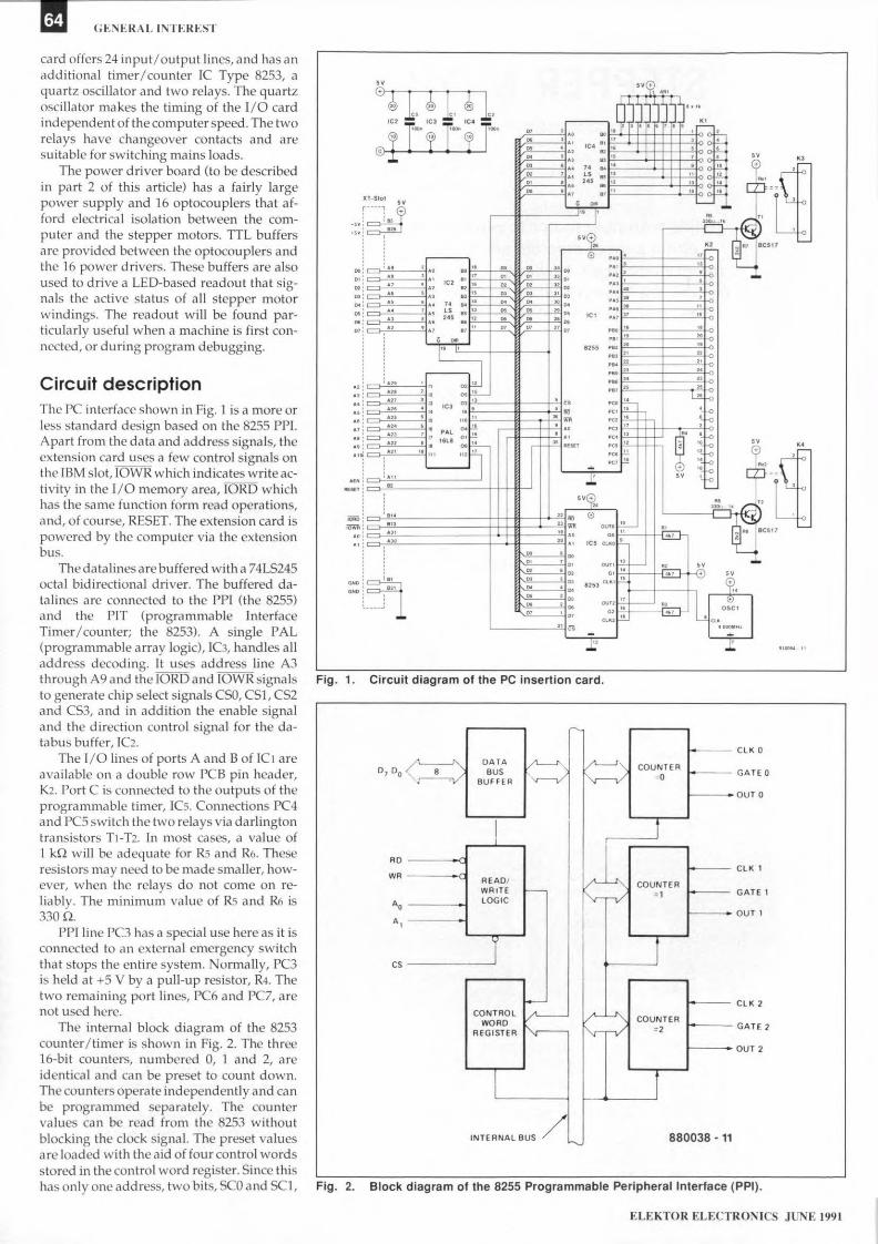
Circuit descriptionThe pe interface shown in Fig. 1 is a more orless standard design based on the 8255 PPl.Apart front the data and address signals, theextension card uses a few control signals onthe IBM slot, IOWR which indicates writeac-tivity in the 1/0 memory area, lORD whichhas the sarne function form read operations,and, of course, RESET. The extension card ispowered by the computer via the extensionbus.
The datalines are buffered with a 74LS245octal bidirectional driver. The buffered da-talirres are connected to the PPI (the 8255)and the PIT (programmable InterfaceTimer/counter; the 8253). A single PAL(programmable array logic), IC3, handles alladdress decoding. lt uses address line A3through A9 and the lORD and IOWR signalsto genera te chi p select signals CSD, CS}, CS2and CS3, and in additiou the enable signaland the direction control signal for the da-tabus buffer, IC2.
The 1/0 lines of ports A and B of IC1 areavailable on a double row PCB pin header,K2. Port Cisconnected to the outpu.ts of theprogrammable tiruer. Ies. Connections PC4and pes switch the two relays via darlingtontransistors Tl-T2. In most cases, a value of1 kQ will be adequere for Rs and R6. Theseresistors may need to be made smaller, how-ever, when the relays da not come on re-liably. The minimurrt value of Rs and R6 is330n,
PPI line pe3 has Cl special use here as it isconnected to an external emergency switchthat stops the entire system. Nonnally, PC3is held at +5 V by a pull-up resistor, R4. Thetwo remaining port lines. PC6 and PC7, arenot used here.
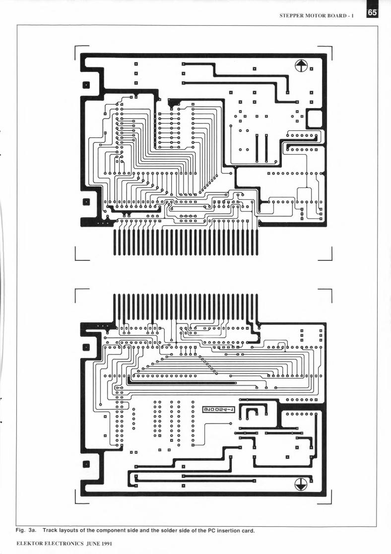
The interna I block diagram of the 8253counter /timer Is shown in Fig. 2. The three16-bit counters, numbered 0, 1 and 2, areidentical and can be preset to count down.Thecounters operate independently and canbe programrned separately. The countervalues can be read from the 8253 withoutblocking the clock slgnal. The preset valuesare loaded with the aid of four control wordsstored in the contro I ward register. Since thishas only one address, two bits, SCO and SCI,
indicate the counter for which the contralward is intended.
Returning to the circuit diagram in Fig. 1,the CLKO through CLK3 inputs 01 the 8253are supplied with a 4-MHz dock signalgenera ted byoscillator block ase,. All threegate (Gx) inputs of the counter/Firner are
tied to +5 V via pull-up resistors.The 8253 is programmed to operate as a
frequency divider. Depending on the presetvalue, a counter divides the oscillator fre-quency down to a particular value, for in-stance, 100 Hz, which is then passed to PPIport C. By loading different counter preset
ELEKTOR ELECTRONICS JUNE t991
values, the step duration of the stepper mo-tors is made iudependent of the computer'sspeed.
IC,l, a 74LS245, fcrms an 8-bit input portwhich is used to signal the status of a set ofend switches fitted on the milling machine.The eight input lines of the port are held at+5 V with the aid of pull-up rcsistors. Theend switches wired to K 1 shou Id, thcrefore.COIU1eetto ground when active.
The address assignment of the ports onthe insertion card, and fheir functtons, nresunuuarizcd in TablesI and 2.
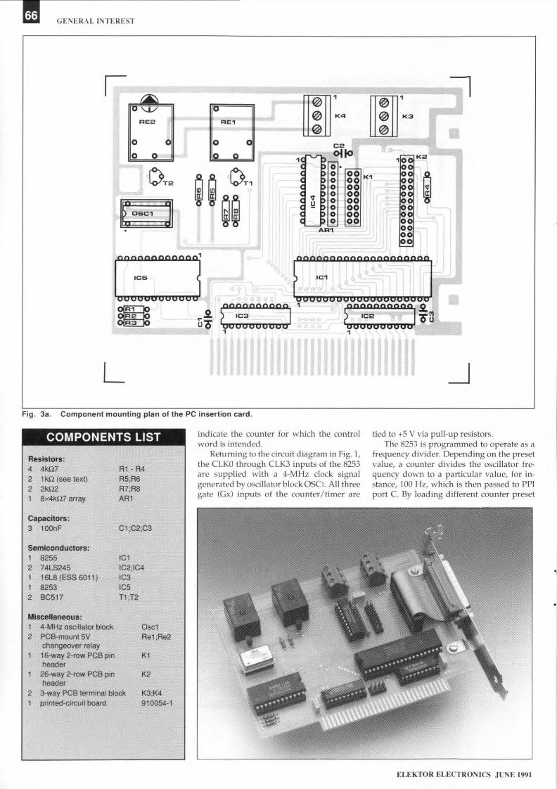
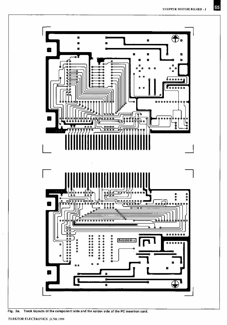
ConstructionPopulanng the double-sided through-platedboard (Fig. 3) should not cause dlificulty. Toruake sure the card remains secure in the peslot. you will need to secure it to CI metalbracket as iound Oll other insertion cards.Here, it is best to use (or rnake) a bracket witha relatively large vertical clearance thatallows the two flatcables and the rclay wiresto pass.
Switch thc computer off, fit the 1/0 cardinto Cl frec slot, and secure thc card to themetal framc at the rear of the pe Switch onthe Pc' and check that a frequency of 4 MHzis present at pins 9,15 and 18 of IC5. In casethe PC will not boot up with the 1/0 card in-serted, you are probably faced with a short-circuit on the board. or a faulty Je.
The data in Tebles 1 and 2, and a few linesof BASLC or Pascal, allow the card to bechecked fcr correct operatton. For instance,reading address [base+B] nC-l) should return1111 111h, which equals FFH, or 256 deci-mal. Next, connect two or three jumpers toKI to pull the input da ta lines logic low. Runthe read test aga in, when the result shouldmatch the set bit pattern (a jumper producesa logic low).
Next, test the PPI by writing to the controlregister at address [base+S] (ODE3H). Set allports to output. then rnake all port Iines legtehigh. The relays should come on.
The scope of this arttele does not allow Cl
more deta.iled description of the way inwhich the 8255 and the 8253 are pro-grarnrned. Fortuuately, plenty of litera ture isavailable that covers the practical use ofthese ICs in great detail.
SoftwareA number of different, fairly complex com-purer programs are required before the frais-ing machirte can bc made to work. The firststep in making a fraised product is to draw itwith the aid of a CAD program, such asAutoCAD or AutoSketch, nnd save thedrawing file in the OXF formet. Next, a pro-gram called AutoPack-Tl is used to convertthe DXF file into Cl formet suitable for furtherprocessing. Autol'ack-Il is a 2112-dimensionversion of the +dhnension program Auto-,Pack. None the Iess, Autol'ack-Il allows youtc view the workpiece in 3-D to the ISOstandard. Also, all siele views of the werk-piece GIn be dtsplayed at the same time, andthe program is capable of calculattng the
ELEKTOR ELECTRONICS JUNE 1991
STEPPER MOTOR HOARI). I
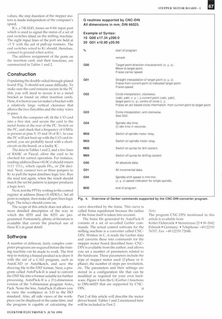
G routines supported by CNC·DINAll dimensions in mm, DIN 66025.
Example 01 Syntax:10 GOOx17.34 y200.020 GOl Xl 0.90 y20.90
% start of program
remark
GOO Target point direction charactertstic (x. y, z).Move to target point.Fraise carrter speed.
G01 Straight interpolation of target point (x, y, z).Fraise from eurrent point to indicated target point.Fraise speed.
G02 Cirele interpolation, clockwlse.(xakt, yakt, x, y, i, j) current point (xakt. yakt),target pcint (x, V), eentre of circle (i, j).Fraise an are based eirele information, from eurrent potnt to target point.
G03 C'rcle interpolation, anti-clockwise.See G02
G04 Spindie idle time.(f) idle time in seconds.
M58 Switch of spindie motor relay.
M59 Switch on spindie motor relay.
Moa Switch on pump for drill coolant.
M09 Switch off pump for drilling coolant.
G90 All absolute data.
G91 All incremental data.
G94 Spindie shift speed in mm/min.(x, y, z) speed indication for single spindie.
M30 end of program.
Fig. 4. Overview of Gerber commands supported by the CNC-DIN converter program.
curve descrtbed by the fraise. This curve iscal.led fraise equ.idistant because the radinsof the fraise itself is taken into nccount.
The fraise file generared by AutoPack-11consists of a set of so-ca lied Gerber com-mands. The actual control softwate for themilling machine is Cl converter called CNC-DIN. Written in C, it reads the Gerber dataand ccnverts these into commands for thestepper rnotor board described here. CNC-DrN is available from the nuther. and allowsyou set a nurnber of pararneters related 10the hardware. These parameters include thetype of stepper motor used (z-phase or 4-phase), the number of steps per revolution,etc. The parameters end their settings arestored 111 a configuration file that can bemodified as required for your own hard-ware. Hgure 4 lists the G (Cerber-) functionsto DIN-66025 that are supported by CNC·DIN. 0
Note:The progn.Hll CNC-DIN mentioned in thisarttele is available fromKolter Elektronik e Steinstrasse 22 • W-5042Erfstadt e Germany .• Telephone: +49 (2235)76707, Fax: +49 (2235) 72048.
Part 2 of this arttele will describe the motordriver board. Tables 1 and 2 mentioned herewill be included in Part 2.
STEPPER MOTOR BOARD - I I
------~~: l a e.a a a 11 a
a a a . a a
aa
• ~a ...
a a .....o a a a 0 a
a aa 0 0 0------.,o 0 0 0-----.o 0 0o 0 0o 0 0o 0 0o 0 0o 0 0
:-1a•
a ~'~ ~
ELEKTOR ELECTRONICS JUNE 1991
Fig. 3a. Track layouts of the component side and the solder side of the pe insertion card.