21
Stereoscopic Imaging for Slow-Moving Autonomous Vehicle Senior Project Proposal Bradley University ECE Department By: Alex Norton Advisor: Dr. Huggins November 15, 2011
| Date post: | 31-Dec-2015 |
| Category: |
Documents |
| Upload: | cecily-houston |
| View: | 221 times |
| Download: | 0 times |
Stereoscopic Imaging for Slow-Moving Autonomous Vehicle
Senior Project ProposalBradley University ECE Department
By: Alex Norton
Advisor: Dr. Huggins
November 15, 2011
Presentation Outline
Introduction to stereoscopic imaging Project goals Previous work Project description Preliminary lab work Equipment list Schedule of tasks for spring

What is Stereoscopic Imaging?
The use of two horizontally aligned, slightly offset cameras taking a pair of images at the same time
By matching corresponding pixels between the two images, the distances to objects can be calculated using triangulation
This depth information can be used to create a 3-D image and terrain map

Project Goals
Learn theory of 3D stereoscopic imaging Investigate existing software (OpenCV and MATLAB) Control cameras Calibrate cameras Take and store images Process images for objects Correlate objects Compute distance to objects Compute terrain map

Previous Work
BirdTrak (Brian Crombie and Matt Zivney, 2003)
Bradley Rover(Steve Goggins, Rob Scherbinski, Pete Lange, 2005)
NavBot (Adam Beach, Nick Wlaznik, 2007)
SVAN (John Hessling, 2010)

Project Description
System block diagram Subsystem block diagrams
CamerasLaptopSoftware
Mode of operationCalibration modeRun mode

System Block Diagram

Cameras Subsystem

Laptop Subsystem
Laptop
Camera 1 Image
Camera 2 Image
User Input
Camera 1 Image capture signal
Movement instructions
Display 3D map on screen
Camera 2 Image capture signal

Software
Calibration Mode
Initial mode of operation Ensures the accuracy of the terrain map
generated in run mode by correcting for lens distortion
Cameras will take images of a chessboard in multiple orientations
Camera intrinsic and distortion parameters can be determined, which are used to correct for distortion in images from un-calibrated cameras

Run Mode
Primary mode of operation entered once cameras are calibrated
Cameras capture a set of images after receiving signals from the laptop
A disparity map is created using the two images and distances to objects are calculated
This information is used to generate a terrain map which is stored in a text file to be used to navigate an autonomous vehicle

Preliminary Lab Work
Current test camera setup

Preliminary Lab Work
Left Camera image Right Camera Image
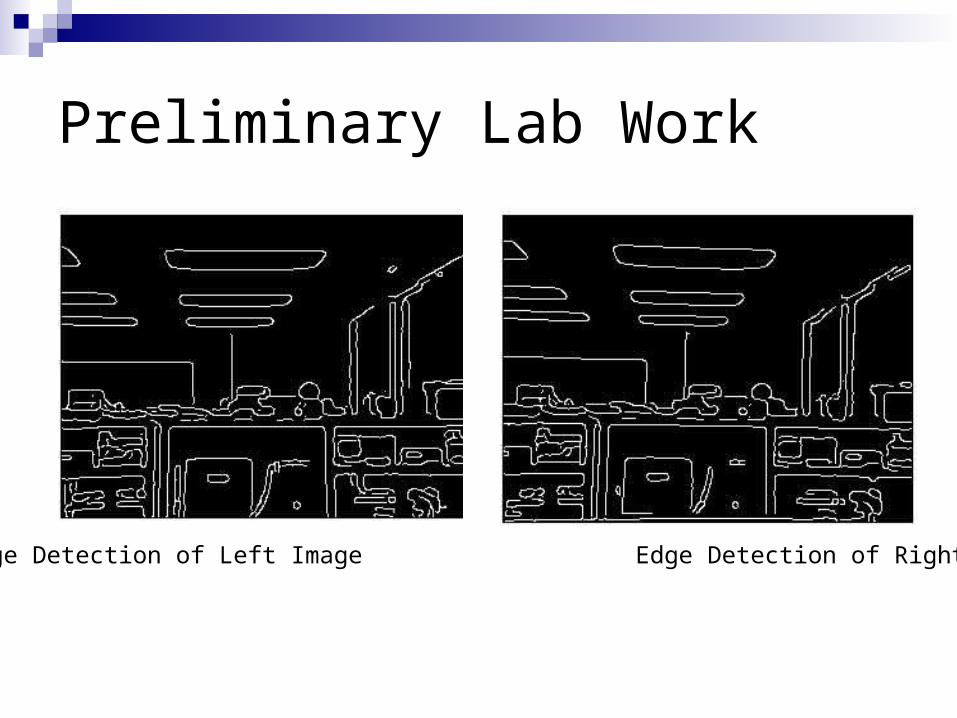
Preliminary Lab Work
Edge Detection of Left Image Edge Detection of Right Image

Preliminary Lab Work
Disparity Map Formed Using Left and Right Images
Represents the differences in corresponding pixels between the left and right cameras
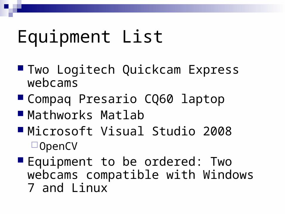
Equipment List
Two Logitech Quickcam Express webcams
Compaq Presario CQ60 laptop Mathworks Matlab Microsoft Visual Studio 2008
OpenCV Equipment to be ordered: Two webcams
compatible with Windows 7 and Linux

Preliminary Lab Work
MATLAB code that sets up the webcams to receive image data from them

Preliminary Lab Work
MATLAB code that gets an image from each camera, filters them using the median filter function, uses the canny edge detection function, and displays the filtered images and edge detected images

Schedule of Spring Tasks
Questions?


