PROJECT DESIGN DOCUMENT FORM (CDM-SSC-PDD) - Version 03 CDM – Executive Board 1 CLEAN DEVELOPMENT MECHANISM PROJECT DESIGN DOCUMENT FORM (CDM-SSC-PDD) Version 03 - in effect as of: 22 December 2006 CONTENTS A. General description of the small scale project activity B. Application of a baseline and monitoring methodology C. Duration of the project activity / crediting period D. Environmental impacts E. Stakeholders’ comments Annexes Annex 1: Contact information on participants in the proposed small scale project activity Annex 2: Information regarding public funding Annex 3: Baseline information Annex 4: Monitoring Information Attachments Attachment1. Baseline Calculations. Attachment2. References Attachment3. Abbreviations
Transcript
PROJECT DESIGN DOCUMENT FORM (CDM-SSC-PDD) - Version 03 CDM – Executive Board
1
CLEAN DEVELOPMENT MECHANISM PROJECT DESIGN DOCUMENT FORM (CDM-SSC-PDD)
Version 03 - in effect as of: 22 December 2006
CONTENTS A. General description of the small scale project activity B. Application of a baseline and monitoring methodology C. Duration of the project activity / crediting period D. Environmental impacts E. Stakeholders’ comments
Annexes Annex 1: Contact information on participants in the proposed small scale project activity Annex 2: Information regarding public funding Annex 3: Baseline information
Annex 4: Monitoring Information Attachments Attachment1. Baseline Calculations.
Attachment2. References
Attachment3. Abbreviations
PROJECT DESIGN DOCUMENT FORM (CDM-SSC-PDD) - Version 03 CDM – Executive Board
2
Revision history of this document Version Number
Date Description and reason of revision
01 21 January 2003
Initial adoption
02 8 July 2005 • The Board agreed to revise the CDM SSC PDD to reflect guidance and clarifications provided by the Board since version 01 of this document.
• As a consequence, the guidelines for completing CDM SSC PDD have been revised accordingly to version 2. The latest version can be found at <http://cdm.unfccc.int/Reference/Documents>.
03 22 December 2006
• The Board agreed to revise the CDM project design document for small-scale activities (CDM-SSC-PDD), taking into account CDM-PDD and CDM-NM.
PROJECT DESIGN DOCUMENT FORM (CDM-SSC-PDD) - Version 03 CDM – Executive Board
3
SECTION A. General description of small-scale project activity A.1 Title of the small-scale project activity: >>
Title : LPG Reduction in Anode Refining and Casting Plant at Sterlite Industries India Limited,
Tuticorin, Tamilnadu, India
Version: 01
Date of Document: 25/03/08.
A.2. Description of the small-scale project activity: >> Background
Sterlite Industries (India) Ltd. (SIIL) is the principal subsidiary of the Vedanta Resources Group. It was the first company in India to set up a Copper Smelter and Refinery in the Private Sector and operate the largest capacity Continuous Cast Copper Wire and Rod Plant. SIIL’s main products are Copper Cathodes and Copper Rods of global quality standards. SIIL have manufacturing facilities all over India and copper mines in Australia.
Purpose of the project activity
LPG is used in copper smelter Anode Casting Plants to supplement heat for maintaining the temperature of molten metal, in order to produce quality castings. The project activity aims to reduce LPG consumption in the Casting process. This is an energy efficiency program, which involves the application of Twin Caster Wheels in an Anode Furnace to achieve higher thermal efficiency and, thereby, reduce LPG consumption. The technology, supplied by SMS DEMAG Hamburg, Germany, was installed in December 2004. Earlier, the Copper Anode Casting was carried out in a Single Caster Wheel, which consumed more heat and, hence, more LPG consumption per unit of production in the copper anode casting plant. The main purposes of the project activity are to reduce LPG consumption, which conserves a fossil fuel that is rapidly being depleted in India, and to reduce greenhouse-gas emissions into the atmosphere. The decision to undertake the high-cost investment in twin-caster technology was made with the dual objectives of reducing fossil fuel consumption and acting in accordance with the company’s commitment to contributing to sustainable development in the country and GHG mitigation.
At its maximum capacity the project will result in 3.84 kt of LPG savings and an energy equivalent of 48.40 GWh / year. The LPG savings in the anode casting and refining process will result in total emission reductions of about 113,650 tonnes of CO2 during crediting period. View of project participant about the project activity’s contribution to sustainable development The Ministry of Environment and Forests, Govt. of India has stipulated the following sustainable development indicators in the interim approval guidelines for CDM projects:
PROJECT DESIGN DOCUMENT FORM (CDM-SSC-PDD) - Version 03 CDM – Executive Board
4
• Social well-being. The CDM project activity should lead to alleviate poverty by generating additional employment, removing social disparities and contributing to the provision of basic amenities and leading to improvements in the quality of life of the people.
• Economic well-being. The CDM project activity should attract additional investment consistent
with the needs of the people. • Environmental well-being. This should include a discussion of impact of the project activity on
resource sustainability and resource degradation, if any, due to proposed activity; bio-diversity friendliness; and reduction of levels of pollution in general.
• Technological well-being. The CDM project activity should lead to transfer of
environmentally safe and sound technologies, prioritizing the renewable sector or energy efficiency projects that are comparable to best practices, in order to assist in upgrading the technological base.
The project activity contributes to the above indicators in the following manner.
Social well-being The project activity generated employment in the area during installation and commissioning. Training was imparted by equipment suppliers, which improved the technical skills of manpower required for operating the twin caster. Economic well-being LPG is a valuable fossil fuel for which domestic sources are being rapidly depleted in India. By avoiding wasteful LPG consumption, the project frees up this resource to be used for other productive purposes in the host country. The project also reduces the variable cost of production. In addition, the project has attracted an investment of Rs.101 Million, thereby contributing to economic well being. Technological well-being The Project activity involves transferring state-of-the art Twin Caster technology to the host country, supplied by world renowned SMS DEMAG of Germany. The technology is energy efficient and environmentally friendly. At the time of decision making for installing Twin Caster technology at SIIL, no company in the world had installed a Twin Caster of the production capacity being used in this project (100 TPH). The maximum-capacity twin caster commissioned was 85 TPH (at Norddeutsche Affinerie, Hamburg Germany). Furthermore, no company in India had applied Twin Caster technology. Since then, only one other company in India has applied twin caster technology (Birla Copper, with a rated production capacity of 65 TPH). The project activity will further contribute to technological well being by promoting the use of state-of-the-art energy-efficient technology in other metallurgical industries across the country. Environmental well-being
The project activity reduces GHG emissions by reducing LPG consumption in an anode casting plant. The project activity provides energy security and environmental well being by reducing the use of fossil fuels.
PROJECT DESIGN DOCUMENT FORM (CDM-SSC-PDD) - Version 03 CDM – Executive Board
5
A.3. Project participants: >> Name of Party involved (*) ((host) indicates a host Party)
Private and/or public entity(ies) project participants (*) (as applicable)
Kindly indicate if the Party involved wishes to be considered as project participant (Yes/No)
India (Host)
Sterlite Industries (India) Limited
No
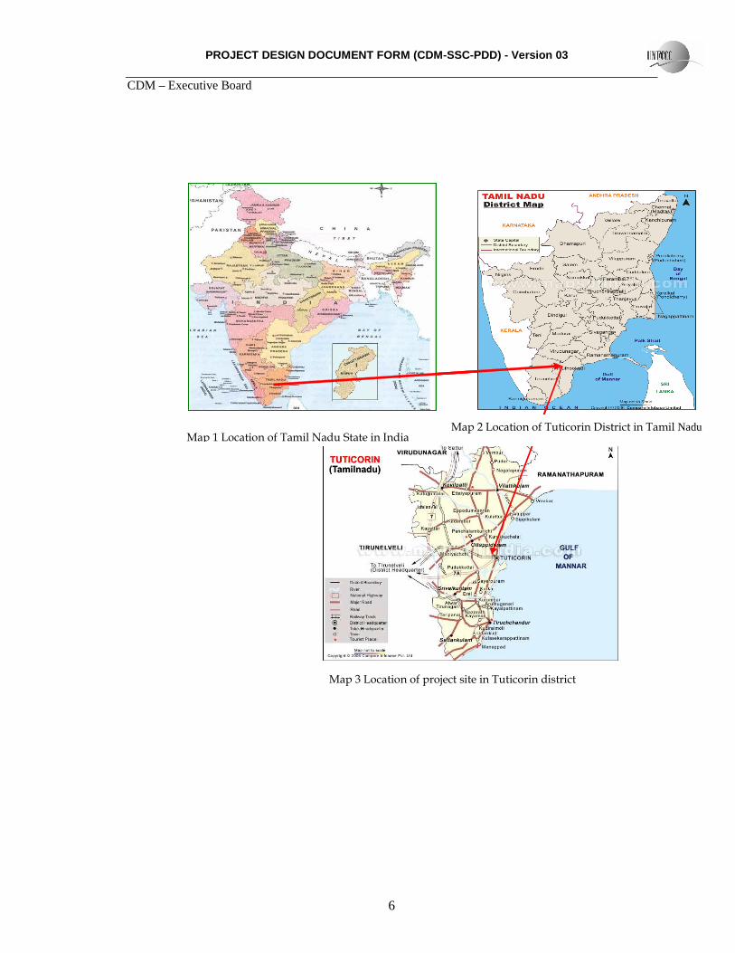
A.4. Technical description of the small-scale project activity : A.4.1. Location of the small-scale project activity : >> A.4.1.1. Host Party(ies): >> India A.4.1.2. Region/State/Province etc.: >> Tamil Nadu State A.4.1.3. City/Town/Community etc: >> SIPCOT Industrial complex, Tuticorin A.4.1.4. Details of physical location, including information allowing the unique identification of this small-scale project activity : >> The project activity is being implemented at Sterlite Industries (India) Limited (Copper Smelter), and is located in State Industries Promotion Corporation of Tamil Nadu (SIPCOT) industrial complex of Tuticorin, on the National High way (N .H.) 45 B, about 10 kilometers from Tuticorin. The geographical location of the project is furnished below.
PROJECT DESIGN DOCUMENT FORM (CDM-SSC-PDD) - Version 03 CDM – Executive Board
6
Map 1 Location of Tamil Nadu State in India Map 2 Location of Tuticorin District in Tamil Nadu
Map 3 Location of project site in Tuticorin district
PROJECT DESIGN DOCUMENT FORM (CDM-SSC-PDD) - Version 03 CDM – Executive Board
7
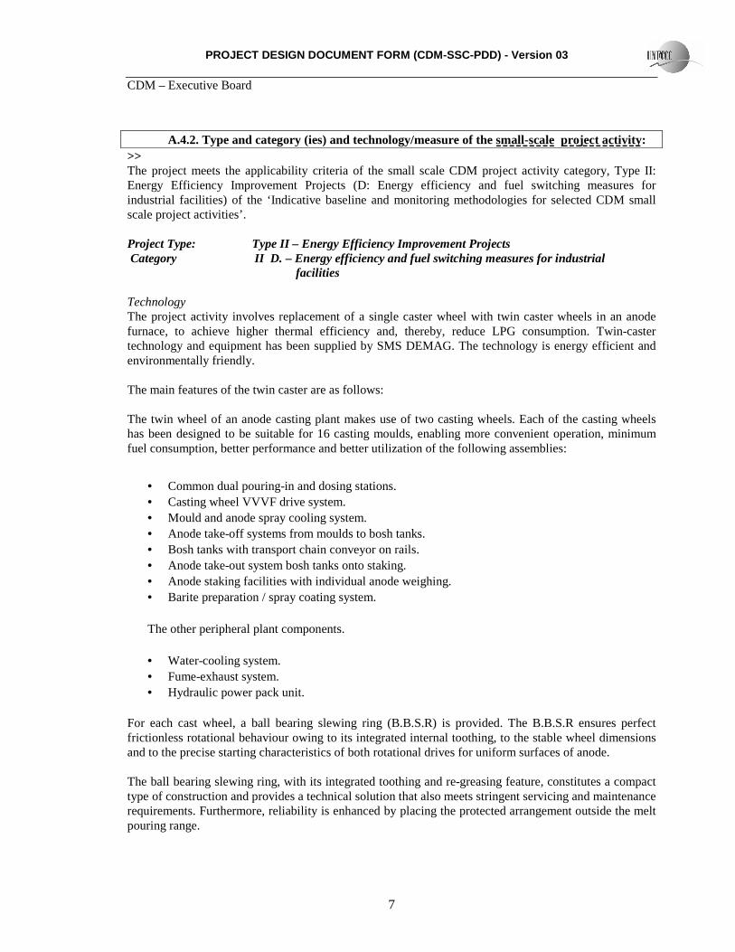
A.4.2. Type and category (ies) and technology/measure of the small-scale project activity: >> The project meets the applicability criteria of the small scale CDM project activity category, Type II: Energy Efficiency Improvement Projects (D: Energy efficiency and fuel switching measures for industrial facilities) of the ‘Indicative baseline and monitoring methodologies for selected CDM small scale project activities’. Project Type: Type II – Energy Efficiency Improvement Projects Category II D. – Energy efficiency and fuel switching measures for industrial facilities Technology The project activity involves replacement of a single caster wheel with twin caster wheels in an anode furnace, to achieve higher thermal efficiency and, thereby, reduce LPG consumption. Twin-caster technology and equipment has been supplied by SMS DEMAG. The technology is energy efficient and environmentally friendly. The main features of the twin caster are as follows: The twin wheel of an anode casting plant makes use of two casting wheels. Each of the casting wheels has been designed to be suitable for 16 casting moulds, enabling more convenient operation, minimum fuel consumption, better performance and better utilization of the following assemblies:
• Common dual pouring-in and dosing stations. • Casting wheel VVVF drive system. • Mould and anode spray cooling system. • Anode take-off systems from moulds to bosh tanks. • Bosh tanks with transport chain conveyor on rails. • Anode take-out system bosh tanks onto staking. • Anode staking facilities with individual anode weighing. • Barite preparation / spray coating system. The other peripheral plant components. • Water-cooling system. • Fume-exhaust system. • Hydraulic power pack unit.
For each cast wheel, a ball bearing slewing ring (B.B.S.R) is provided. The B.B.S.R ensures perfect frictionless rotational behaviour owing to its integrated internal toothing, to the stable wheel dimensions and to the precise starting characteristics of both rotational drives for uniform surfaces of anode.
The ball bearing slewing ring, with its integrated toothing and re-greasing feature, constitutes a compact type of construction and provides a technical solution that also meets stringent servicing and maintenance requirements. Furthermore, reliability is enhanced by placing the protected arrangement outside the melt pouring range.
PROJECT DESIGN DOCUMENT FORM (CDM-SSC-PDD) - Version 03 CDM – Executive Board
8
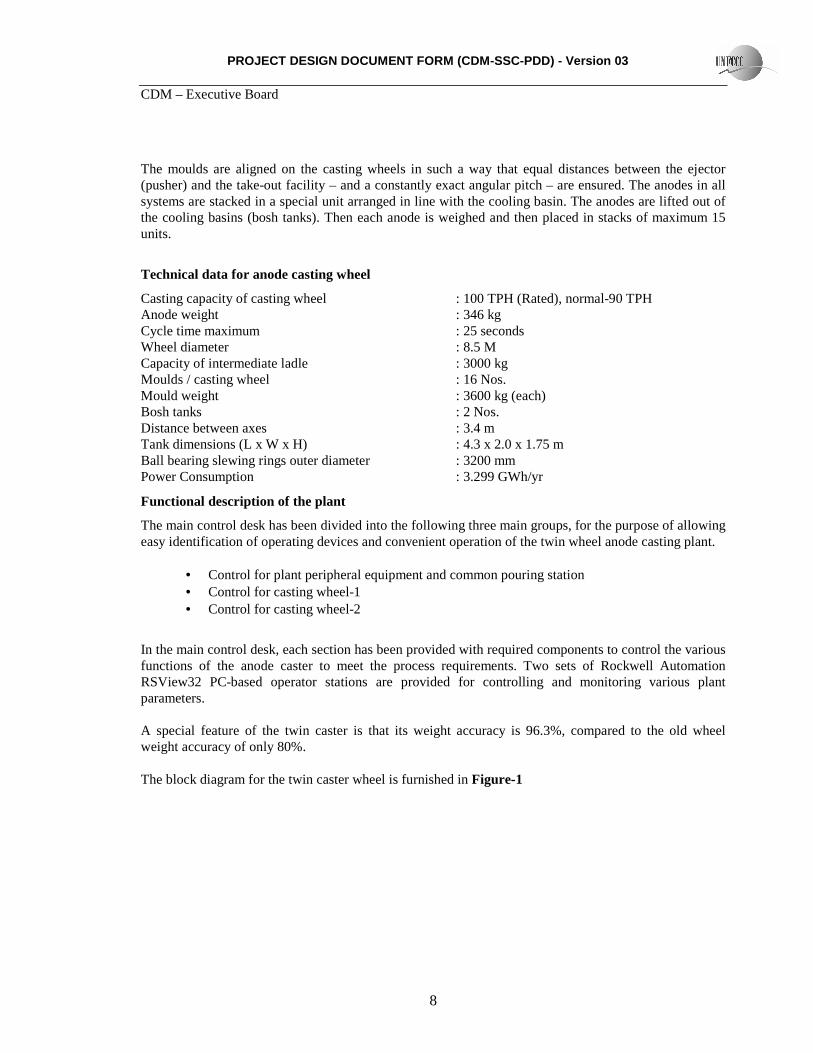
The moulds are aligned on the casting wheels in such a way that equal distances between the ejector (pusher) and the take-out facility – and a constantly exact angular pitch – are ensured. The anodes in all systems are stacked in a special unit arranged in line with the cooling basin. The anodes are lifted out of the cooling basins (bosh tanks). Then each anode is weighed and then placed in stacks of maximum 15 units.
Technical data for anode casting wheel
Casting capacity of casting wheel : 100 TPH (Rated), normal-90 TPH Anode weight : 346 kg Cycle time maximum : 25 seconds Wheel diameter : 8.5 M Capacity of intermediate ladle : 3000 kg Moulds / casting wheel : 16 Nos. Mould weight : 3600 kg (each) Bosh tanks : 2 Nos. Distance between axes : 3.4 m Tank dimensions (L x W x H) : 4.3 x 2.0 x 1.75 m Ball bearing slewing rings outer diameter : 3200 mm Power Consumption : 3.299 GWh/yr
Functional description of the plant
The main control desk has been divided into the following three main groups, for the purpose of allowing easy identification of operating devices and convenient operation of the twin wheel anode casting plant.
• Control for plant peripheral equipment and common pouring station • Control for casting wheel-1 • Control for casting wheel-2
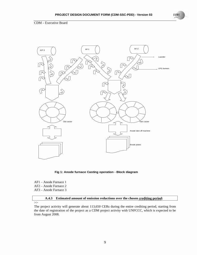
In the main control desk, each section has been provided with required components to control the various functions of the anode caster to meet the process requirements. Two sets of Rockwell Automation RSView32 PC-based operator stations are provided for controlling and monitoring various plant parameters. A special feature of the twin caster is that its weight accuracy is 96.3%, compared to the old wheel weight accuracy of only 80%. The block diagram for the twin caster wheel is furnished in Figure-1
PROJECT DESIGN DOCUMENT FORM (CDM-SSC-PDD) - Version 03 CDM – Executive Board
A.4.3 Estimated amount of emission reductions over the chosen crediting period: >> The project activity will generate about 113,650 CERs during the entire crediting period, starting from the date of registration of the project as a CDM project activity with UNFCCC, which is expected to be from August 2008.
PROJECT DESIGN DOCUMENT FORM (CDM-SSC-PDD) - Version 03 CDM – Executive Board
10
Annual estimated anticipated emission reductions from the project activity are furnished below.
Total Emission reductions (tCO2e) 113650 Total number of crediting years 10 Annual average over the crediting period of estimated reductions (tCO2e) 11365
In the above table the year 2008 corresponds to the period starting from 01.08.2008 to 31.07.2009. Similar interpretation shall apply for the remaining years. A.4.4. Public funding of the small-scale project activity : >> The project activity does not involve any public funding from Annex 1 countries. See also statement in Annex 2. A.4.5. Confirmation that the small-scale project activity is not a debundled component of a large scale project activity: The project proponent hereby confirms that the project activity is neither a debundled component of a larger project activity nor bundled to form a large scale project activity (>180 GWhth). The annual LPG savings by the project activity are 3.840 kt, with an energy equivalent of 48.40 GWhth / year, which is well below 180 GWhth thermal savings. Hence, UNFCCC indicative simplified modalities and procedures can be applied The project proponent further confirms that they have not registered any small scale CDM activity or applied to register another small scale CDM project activity within 1 km of the project boundary, in the same project category and technology/measure in the previous 2 years.
PROJECT DESIGN DOCUMENT FORM (CDM-SSC-PDD) - Version 03 CDM – Executive Board
11
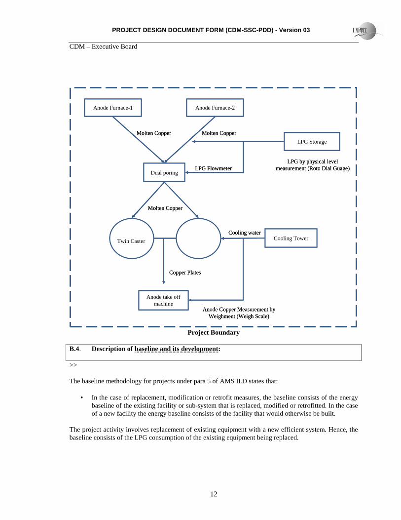
SECTION B. Application of a baseline and monitoring methodology B.1. Title and reference of the approved baseline and monitoring methodology applied to the small-scale project activity: >> Project type : Type II – Energy Efficiency Improvement Projects Category : II D – Energy Efficiency and Fuel Switching Measures for Industrial Facilities Reference1 : AMS II D., Version: 11, Scope: 4, EB 35 B.2 Justification of the choice of the project category: >> The project activity is an energy efficiency improvement project which reduces LPG consumption in a single industrial facility i.e., at Sterlite Industries (India) Limited. The efficiency improvement is achieved by replacing an old single caster with new twin caster. The project activity falls under Type- AMS II D – Energy Efficiency and Fuel switching measures in Industrial Facilities. Demonstration for being with in the limits of SSC throughout the crediting period The estimated LPG savings from replacing a single caster with twin caster, at 100% production capacity, is 3.840 kt which is equivalent to 48.40 GWhth per year. This is well below the SSC limit of 180 GWhth per year. Hence, UNFCCC indicative simplified modalities and procedures can be applied. The LPG savings are estimated for 100% production capacity and cannot be enhanced due to limitations in design. Hence, the project promoters hereby confirm that the project activity will not exceed the small scale limit of 180 GWhth of thermal energy saving during the crediting period. The average lifetime of single casters is 30 years. Given this equipment lifetime, the existing single caster would be expected to require replacement during the year 2022 in the absence of the project activity. Hence, the project does not claim carbon credits beyond the year 2022. B.3. Description of the project boundary: >> As per the guidelines mentioned in Type II D of the simplified modalities and procedures for small-scale CDM project activities, the project boundary is the physical, geographical site of the industrial facility and processes and equipments that are affected by the project activity. The project boundary encompasses the Twin Caster wheel in the anode casting plant and the associated equipment, including common dual pouring-in and dosing stations, casting wheel VVVF drive system, anode take off systems from moulds to bosh tanks, bosh tanks with transport chain conveyor on rails, anode take out system, anode staking facilities with individual anode weighing, barite preparation, cooling water system, fume exhaust system and hydraulic power pack unit.
PROJECT DESIGN DOCUMENT FORM (CDM-SSC-PDD) - Version 03 CDM – Executive Board
12
Anode Furnace-1 Anode Furnace-2
Dual poring
Anode take off machine
Cooling Tower
LPG Storage
Molten Copper Molten Copper
LPG Flowmeter
Molten Copper
Twin Caster
Cooling water
Copper Plates
LPG by physical level measurement (Roto Dial Guage)
Anode Copper Measurement by Weighment (Weigh Scale)
Anode Furnace-1 Anode Furnace-2
Dual poring
Anode take off machine
Cooling Tower
LPG Storage
Molten Copper Molten Copper
LPG Flowmeter
Molten Copper
Twin Caster
Cooling water
Copper Plates
LPG by physical level measurement (Roto Dial Guage)
Anode Copper Measurement by Weighment (Weigh Scale)
Project Boundary
B.4. Description of baseline and its development: >> The baseline methodology for projects under para 5 of AMS II.D states that:
• In the case of replacement, modification or retrofit measures, the baseline consists of the energy baseline of the existing facility or sub-system that is replaced, modified or retrofitted. In the case of a new facility the energy baseline consists of the facility that would otherwise be built.
The project activity involves replacement of existing equipment with a new efficient system. Hence, the baseline consists of the LPG consumption of the existing equipment being replaced.
PROJECT DESIGN DOCUMENT FORM (CDM-SSC-PDD) - Version 03 CDM – Executive Board
13
• In the absence of the project activity, the existing facilities would continue to consume energy at a historical average level, until the facility would likely to be replaced, modified or retrofitted in the absence of the of the CDM project activity. From that point in time on, the baseline is assumed to correspond to the project activity, and no emission reductions are assumed to occur.
• Each energy form in the emission baseline is multiplied by an emission coefficient (in kg
CO2e/kWh). For the electricity displaced, the emission coefficient is calculated in accordance with provisions under category I.D. For fossil fuels, the IPCC default values for emission coefficients may be used.
The project activity is reducing LPG consumption. The IPCC default value for the emission coefficient for LPG has been used. S.No Parameter Value Notation Source 1 Net Calorific
value of LPG 47.3 TJ/kt NCVL Revised 2006 IPCC Guidelines for
National Greenhouse Gas Inventories)
2 Emission Factor of LPG
63.100 tCO2/TJ EF Revised 2006 IPCC Guidelines for National Greenhouse Gas Inventories
3. Quantity of LPG consumed
Monitored value FCi,j,y From plant log books, records and purchase receipts
4 Carbon to Carbon-dioxide conversion factor
44/12 Stiochiometry.
B.5. Description of how the anthropogenic emissions of GHG by sources are reduced below those that would have occurred in the absence of the registered small-scale CDM project activity: According to Attachment A to Appendix B, small-scale modalities and procedures of CDM, project participants shall demonstrate that the project activity would not have occurred anyway due to at least one of the barriers mentioned in Attachment C which are as follows: • Investment barrier • Technological barrier • Barrier due to prevailing practice • Other barriers The project activity is subject to both prevailing practice and technological barriers. Central State and Government Policy The Bureau of Energy Efficiency (BEE) is a statutory body working under the Ministry of Power, Government of India. It was established to promote energy efficiency and its conservation, and was primarily aimed to encourage (rather than making mandatory) energy efficiency in the industrial and commercial sectors of the country. The Tamil Nadu State Electricity Board (TNEB) also encourages, but does not mandate, energy efficiency improvements.
PROJECT DESIGN DOCUMENT FORM (CDM-SSC-PDD) - Version 03 CDM – Executive Board
14
The project activity was implemented voluntarily by the project promoter, SIIL. The measure adopted was not required by any legal mandate or State/National policies. Social and environmental responsibility The main factors that influenced the project promoter’s decision to implement this climate change initiative are: - Reduced fossil fuel consumption through improved energy efficiency, and - GHG emission reductions due to reduced use of fossil fuels. The company started operations during the year 1994. Since then, as a part of the company’s commitment to social and environmental responsibility, the management has been continuously striving to reduce its greenhouse-gas emissions by identifying various energy-efficient technologies in their industrial facility, and aims to be the most energy efficient industry in the sector. The project proponent has undertaken energy audits by an internal team of engineers and by external agencies on a continuous basis. Although a number of measures were identified for reducing energy consumption, management could not initiate implementation of them due to high investment costs for adopting technologies, unavailability of local technologies, and risks associated with adopting practices that were new to the industry. The LPG consumption in the Anode Casting plant is one of the most energy intensive areas in the SIIL. A detailed analysis of the energy consumption was done, and it was found that significant energy-efficiency improvements could be achieved by replacing the single caster wheel with a twin caster. There are only two twin caster technology suppliers in the international market. They are: SMS – DeMag, West Germany and Autokumpu, Finland. No Indian company had installed twin caster technology with a capacity of 100 TPH prior to the installation of the twin caster at SIIL. In considering the investment in this energy-efficiency measure, the project proponent was faced with both prevailing practice and technological barriers associated with project implementation. However, it was perceived that the availability of carbon financing through the sale of carbon credits (generated by the project activity) would help to alleviate the severity of these barriers. In accordance with the applied methodology, as the project activity involves the replacement of existing equipment, the baseline consists of the energy baseline of the existing facility or sub-system that is replaced, i.e. the plant with the continued use of the existing single caster, with no reduction in the LPG consumption and its associated greenhouse-gas reductions. The key barriers faced by the project proponent for the project activity are discussed below. Barriers due to prevailing practices Adoption of state-of-the-art twin-caster technology Single-caster technology is widely used in Indian ferrous-alloy and non-ferrous-metal industries for manufacturing anode and continuous castings. The project activity, i.e., the replacement of a single-caster system with twin-caster technology, has not penetrated Indian industry due to the unavailability of local technology/equipment suppliers, the complexity of the technology, high investments, and unavailability of trained manpower for maintenance and operation of the equipment. At the time of decision making for installing twin-caster technology at SIIL, no company in the world had installed a twin caster of 100 TPH production capacity. The maximum-capacity twin caster
PROJECT DESIGN DOCUMENT FORM (CDM-SSC-PDD) - Version 03 CDM – Executive Board
15
commissioned was only 85 TPH, at Norddeutsche Affinerie, Hamburg Germany. Since then, only one company in India has adopted twin-caster technology (Birla Copper, which has a rated production capacity of only 65 TPH). No other company has installed a twin caster in India. Documentation supporting this fact will be made available to the validator. Source: equipment supplier’s client list. The adoption of twin-caster technology is not a common practice in India. Implementing high-cost measures for reducing energy consumption In Indian industries, energy-efficiency measures will be implemented for reducing energy consumption in large-scale and energy-intensive industries like aluminum, fertilizers, pulp and paper, petrochemicals, chemical industries, chloro alkali, tyre manufacturing industries, automobile, cement, iron and steel etc. The Bureau of Energy Efficiency (BEE) is an agency working under the Ministry of Power. BEE encourages industries to reduce their energy consumption. Awards are distributed, but it is not mandatory to implement energy-efficiency measures. The majority of Indian companies will present papers demonstrating various measures implemented in their respective industries in order to compete for BEE awards. The common practice in Indian industries is to invest in low-cost measures, where the investment is less than 20 million rupees in a given year for implementing energy-efficiency measures. Very few energy-intensive industries in the country will implement measures where the investment for reducing energy consumption costs more than 50 million rupees in a given year. Sterlite Industries India Ltd is one of only two companies in the country that invested more than Rs.100 million in a single year for implementing various energy efficiency measures.
PROJECT DESIGN DOCUMENT FORM (CDM-SSC-PDD) - Version 03 CDM – Executive Board
16
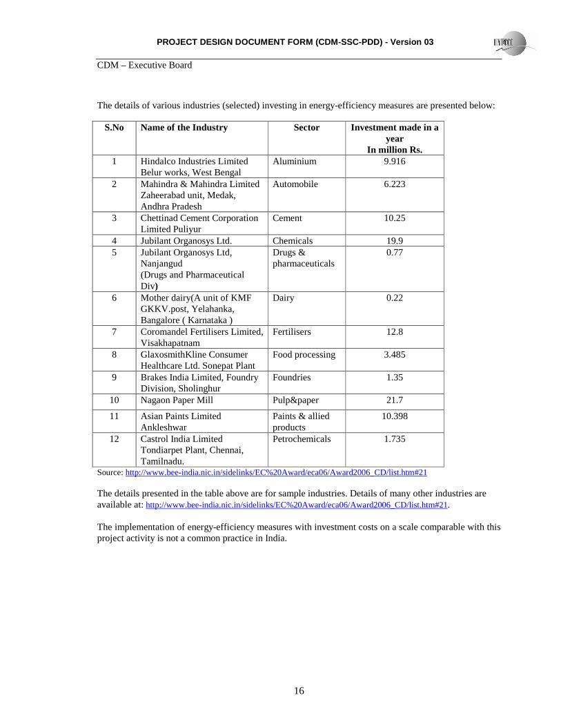
The details of various industries (selected) investing in energy-efficiency measures are presented below:
S.No Name of the Industry Sector Investment made in a year
In million Rs. 1 Hindalco Industries Limited
Belur works, West Bengal Aluminium 9.916
2 Mahindra & Mahindra Limited Zaheerabad unit, Medak, Andhra Pradesh
The details presented in the table above are for sample industries. Details of many other industries are available at: http://www.bee-india.nic.in/sidelinks/EC%20Award/eca06/Award2006_CD/list.htm#21. The implementation of energy-efficiency measures with investment costs on a scale comparable with this project activity is not a common practice in India.
PROJECT DESIGN DOCUMENT FORM (CDM-SSC-PDD) - Version 03 CDM – Executive Board
17
Technological barriers Skilled and trained manpower As per the Additionality Tool, lack of skilled and trained manpower is defined as a technological barrier: ‘Skilled and/or properly trained labour to operate and maintain the technology is not available, which leads to an unacceptably high risk of equipment disrepair and malfunctioning or other underperformance’. The new technology adopted under this project activity does not have a pronounced presence in India because of its advanced features and electronic controls, which require skilled personnel for operation & maintenance. Such skilled personnel were not available locally, as there are no technology providers or twin caster equipment suppliers in India. As a result, the project proponent is totally dependent on the foreign technology provider and equipment supplier (SMS DEMAG). This situation presents an unacceptably high risk to the project proponent in adopting the twin caster technology without the support of the CDM. Risks pertaining to technological failures As per the Additionality Tool, the risk of technological failures is a barrier when ‘the process/technology failure risk in the local circumstances is significantly greater than for other technologies that provide services or outputs comparable to those of the proposed CDM project activity, as demonstrated by relevant scientific literature or technology manufacturer information’. Twin caster design presents a number of risks related to technological failure that are significantly greater than the standard single-caster technology that is normally adopted in this industry in India. The major risks of technological failure associated with implementation of project activity are as follows: Dimensional accuracy The dimensional accuracy of copper anode plates (98% accuracy and above) is critical in copper smelter anode casting, as per customer requirements and for satisfactory refining of the metal into cathode plates. If the required dimensional accuracy is not achieved, the product needs chipping before refining and requires additional manpower and machine time. Otherwise the machine needs to be operated at less than its rated capacity. The dimensional accuracy of twin-caster technology is unproven under local circumstances. Possibility of fire hazards due to its design Twin casters are designed with the instrument cables, load shell and hydraulic systems – which are easily flammable due to their physical properties – located very near to hot metal and exposed to very high temperatures. With any human error leading to spillage of molten metal, there is a high risk of fire that can damage the entire plant and cause injury to the workmen. Hence, the adoption of twin-caster technology requires that workers must be given extensive additional training for operating the plant for avoiding molten metal spillages. Effect of furnace elevation Twin caster design requires that the furnace and launders be placed high enough to allow sufficient slope for metal to flow from the furnace to the caster. To provide sufficient slope for launder, the caster needs to be installed below ground level and all of the cables for the casting ladles and other valve cables must be laid close to the hot metal zone. Due to high temperatures in this zone, there is a high risk of fire that can result in equipment damage and injury to the workers.
PROJECT DESIGN DOCUMENT FORM (CDM-SSC-PDD) - Version 03 CDM – Executive Board
18
Lubrication system for wheel bearing and pinions Twin casters are designed with the ball bearing slewing rings and the slewing drive for each casting wheel lubricated from a centralised automatic lubrication system. Additionally, as a procedure, initially the feed line needs to be connected to the main manifold and then to individual lubricating points. As per the design, about 12 lubrication points are located around each wheel in a concealed manner. Inability to physically inspect the lubrication points is a major constraint of the twin caster. There is a risk of the monitor indicating that the lubrication system is functioning normally, when in reality the lubrication system may have malfunctioned. This can cause damage to various costly components of the twin caster or breakdown of the machine. In a single caster, there is no comparable risk related to malfunctioning of lubrication system, as physical inspection is simple and close monitoring of the lubrication system is possible. Monitoring of air and oil pressure The twin caster machine wheel operates using a hydraulic and pneumatic system. For smooth and trouble-free operation, it is critical that the hydraulic and air pressures are monitored. With any uncertainty about the hydraulic and air pressures, the whole casting operation needs to be stopped. This is due to a pressure-interlocking system for rotation of the wheels. Resumption of operations takes a long time. Furthermore, any leakage in the oil or air lines may lead to pressure drops and, subsequently, cause breakdowns of the entire plant. With a single caster wheel, there is no oil and air pressure interlocking system for rotation of the wheel. Inventory of twin caster components The anode take-off machines are equipped with separate hydraulic rotation drives. The units serve to take the anodes out of the bosh tank and put them on the racks of the stacking facility. These hydro motors are specially designed and coupled with encoders with gear arrangements. Lubrication oil leakages and gear failures are common in this type of special equipment, and frequently cause equipment damage. There are no local twin caster equipment suppliers. Therefore, maintaining inventory for motors and other components is critical. Lack of available replacement components to repair machine breakdowns can cause heavy production losses. These characteristics of twin-caster technology represent risks related to technological failure that are significantly greater than the standard single-caster technology that is normally adopted in this industry in India. B.6. Emission reductions:
B.6.1. Explanation of methodological choices: >> The project activity involves an energy-efficiency improvement in a single existing industrial facility that reduces fossil fuel consumption i.e., LPG. Hence, the applicable baseline methodology is of the methodology of AMS IID, version 11, EB 35. In accordance with the methodology, in the absence of the CDM project activity, the existing facility would continue to consume energy at historical average levels, until the time at which the industrial or mining and mineral production facility would be likely to be replaced, modified or retrofitted in the absence of the CDM project activity.
PROJECT DESIGN DOCUMENT FORM (CDM-SSC-PDD) - Version 03 CDM – Executive Board
19
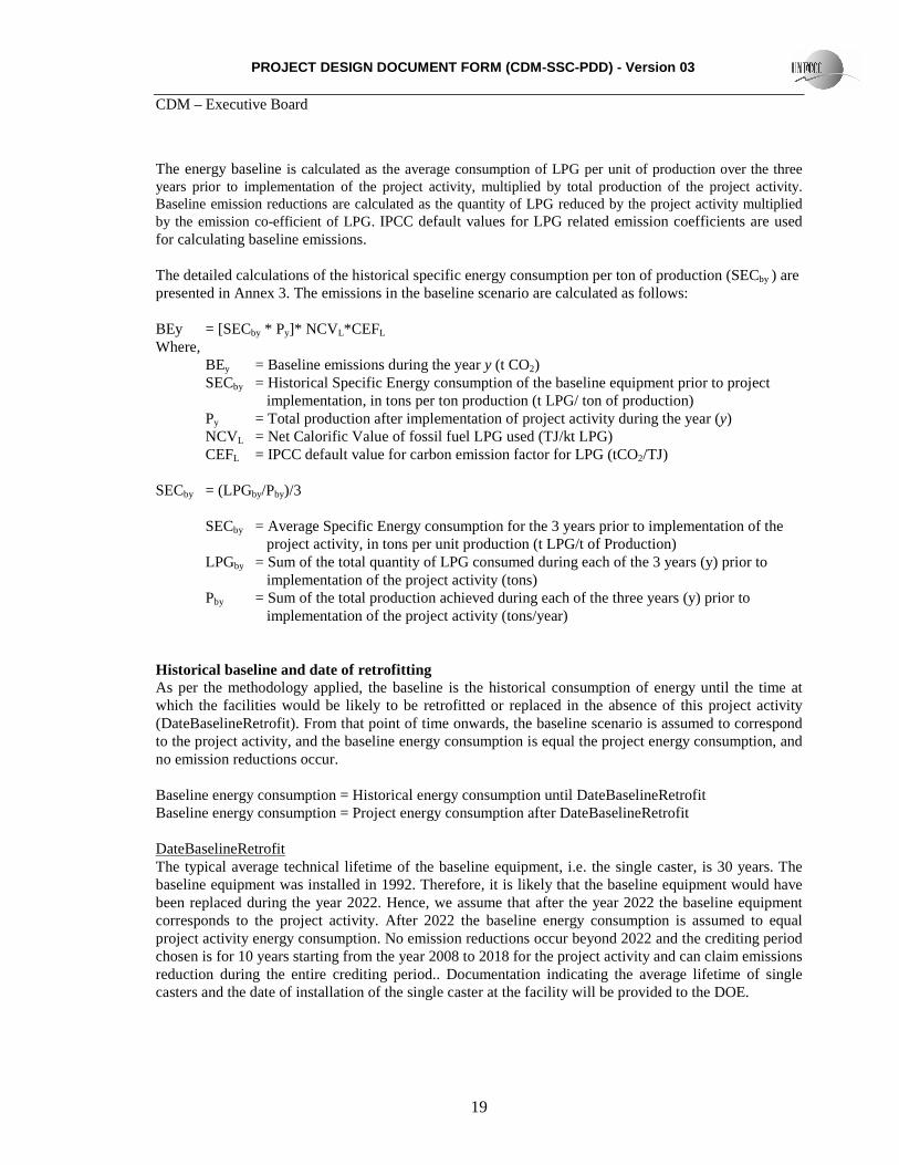
The energy baseline is calculated as the average consumption of LPG per unit of production over the three years prior to implementation of the project activity, multiplied by total production of the project activity. Baseline emission reductions are calculated as the quantity of LPG reduced by the project activity multiplied by the emission co-efficient of LPG. IPCC default values for LPG related emission coefficients are used for calculating baseline emissions. The detailed calculations of the historical specific energy consumption per ton of production (SECby ) are presented in Annex 3. The emissions in the baseline scenario are calculated as follows: BEy = [SECby * Py]* NCV L*CEFL Where,
BEy = Baseline emissions during the year y (t CO2) SECby = Historical Specific Energy consumption of the baseline equipment prior to project implementation, in tons per ton production (t LPG/ ton of production) Py = Total production after implementation of project activity during the year (y) NCVL = Net Calorific Value of fossil fuel LPG used (TJ/kt LPG) CEFL = IPCC default value for carbon emission factor for LPG (tCO2/TJ)
SECby = (LPGby/Pby)/3
SECby = Average Specific Energy consumption for the 3 years prior to implementation of the project activity, in tons per unit production (t LPG/t of Production)
LPGby = Sum of the total quantity of LPG consumed during each of the 3 years (y) prior to implementation of the project activity (tons) Pby = Sum of the total production achieved during each of the three years (y) prior to implementation of the project activity (tons/year) Historical baseline and date of retrofitting As per the methodology applied, the baseline is the historical consumption of energy until the time at which the facilities would be likely to be retrofitted or replaced in the absence of this project activity (DateBaselineRetrofit). From that point of time onwards, the baseline scenario is assumed to correspond to the project activity, and the baseline energy consumption is equal the project energy consumption, and no emission reductions occur. Baseline energy consumption = Historical energy consumption until DateBaselineRetrofit Baseline energy consumption = Project energy consumption after DateBaselineRetrofit DateBaselineRetrofit The typical average technical lifetime of the baseline equipment, i.e. the single caster, is 30 years. The baseline equipment was installed in 1992. Therefore, it is likely that the baseline equipment would have been replaced during the year 2022. Hence, we assume that after the year 2022 the baseline equipment corresponds to the project activity. After 2022 the baseline energy consumption is assumed to equal project activity energy consumption. No emission reductions occur beyond 2022 and the crediting period chosen is for 10 years starting from the year 2008 to 2018 for the project activity and can claim emissions reduction during the entire crediting period.. Documentation indicating the average lifetime of single casters and the date of installation of the single caster at the facility will be provided to the DOE.
PROJECT DESIGN DOCUMENT FORM (CDM-SSC-PDD) - Version 03 CDM – Executive Board
20
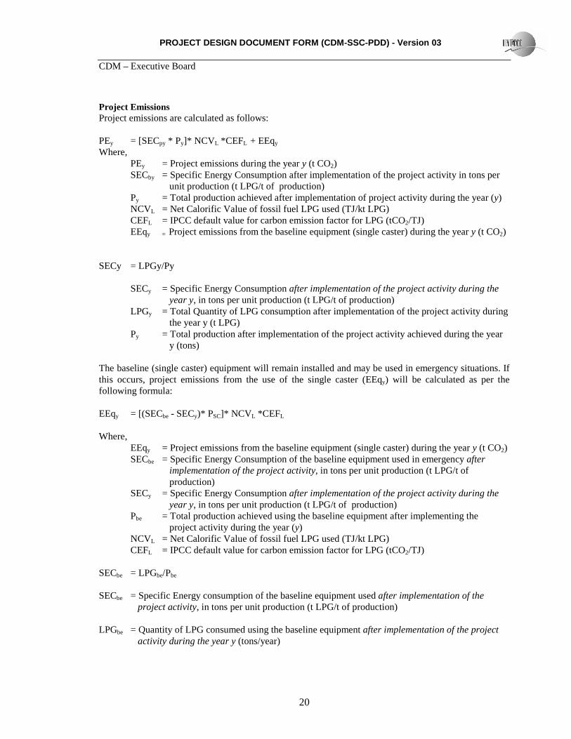
Project Emissions Project emissions are calculated as follows: PEy = [SECpy * Py]* NCV L *CEFL + EEqy
Where, PEy = Project emissions during the year y (t CO2) SECby = Specific Energy Consumption after implementation of the project activity in tons per
unit production (t LPG/t of production) Py = Total production achieved after implementation of project activity during the year (y) NCVL = Net Calorific Value of fossil fuel LPG used (TJ/kt LPG) CEFL = IPCC default value for carbon emission factor for LPG (tCO2/TJ) EEqy = Project emissions from the baseline equipment (single caster) during the year y (t CO2)
SECy = LPGy/Py
SECy = Specific Energy Consumption after implementation of the project activity during the year y, in tons per unit production (t LPG/t of production)
LPGy = Total Quantity of LPG consumption after implementation of the project activity during the year y (t LPG)
Py = Total production after implementation of the project activity achieved during the year y (tons)
The baseline (single caster) equipment will remain installed and may be used in emergency situations. If this occurs, project emissions from the use of the single caster (EEqy) will be calculated as per the following formula: EEqy = [(SECbe - SECy)* PSC]* NCV L *CEFL Where,
EEqy = Project emissions from the baseline equipment (single caster) during the year y (t CO2) SECbe = Specific Energy Consumption of the baseline equipment used in emergency after implementation of the project activity, in tons per unit production (t LPG/t of production) SECy = Specific Energy Consumption after implementation of the project activity during the year y, in tons per unit production (t LPG/t of production) Pbe = Total production achieved using the baseline equipment after implementing the project activity during the year (y) NCVL = Net Calorific Value of fossil fuel LPG used (TJ/kt LPG) CEFL = IPCC default value for carbon emission factor for LPG (tCO2/TJ)
SECbe = LPGbe/Pbe SECbe = Specific Energy consumption of the baseline equipment used after implementation of the project activity, in tons per unit production (t LPG/t of production)
LPGbe = Quantity of LPG consumed using the baseline equipment after implementation of the project activity during the year y (tons/year)
PROJECT DESIGN DOCUMENT FORM (CDM-SSC-PDD) - Version 03 CDM – Executive Board
21
Pbe = Total production using the baseline equipment after implementation of the project
activity achieved during the year y (tons/year) The project emissions due to electricity consumption for operating twin caster are not quantified. The power consumption per ton copper anode production is lower in the project activity case than in the baseline (i.e. with single caster). The details documenting this fact are furnished in Attachment 2. This is a conservative assumption. Leakage AMS II D., Version 11, Scope 4, requires that leakage be considered, “If the energy efficiency technology is equipment transferred from another activity or if the existing equipment is transferred to another activity.” The energy efficiency equipment (twin caster) for the proposed project activity is new and is not transferred from another activity. The existing equipment (single caster) will not be transferred to another activity. Hence, the consideration of leakage is not required and we assume that no leakage emissions will occur. Ly = 0 Leakage quantity during the year y (t CO2) EMISSION REDUCTIONS For each year of the crediting period the emission reductions are calculated as: ERy = BEy – PEy – Ly Where
ERy = Emission reductions during the year y (t CO2) BEy = Baseline emissions during the year y (t CO2) PEy = Project emissions during the year y (t CO2) Ly = Leakage quantity during the year y ((t CO2)
Since leakage (Ly) is not anticipated, the emission reductions are the difference between baseline emissions and project emissions.
PROJECT DESIGN DOCUMENT FORM (CDM-SSC-PDD) - Version 03 CDM – Executive Board
22
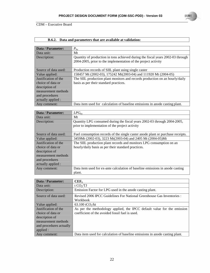
B.6.2. Data and parameters that are available at validation:
Data / Parameter: Pby Data unit: Mt Description: Quantity of production in tons achieved during the fiscal years 2002-03 through
2004-2005, prior to the implementation of the project activity
Source of data used: Production records of SIIL plant using single caster Value applied: 158457 Mt (2002-03), 175242 Mt(2003-04) and 111920 Mt (2004-05) Justification of the choice of data or description of measurement methods and procedures actually applied :
The SIIL production plant monitors and records production on an hourly/daily basis as per their standard practices.
Any comment: Data item used for calculation of baseline emissions in anode casting plant. Data / Parameter: LPGby Data unit: Mt Description: Quantity LPG consumed during the fiscal years 2002-03 through 2004-2005,
prior to implementation of the project activity
Source of data used: Fuel consumption records of the single caster anode plant or purchase receipts. Value applied: 3459Mt (2002-03), 3223 Mt(2003-04) and 2405 Mt (2004-05)Mt Justification of the choice of data or description of measurement methods and procedures actually applied :
The SIIL production plant records and monitors LPG consumption on an hourly/daily basis as per their standard practices.
Any comment: Data item used for ex-ante calculation of baseline emissions in anode casting
plant. Data / Parameter: CEFL Data unit: t CO2/TJ Description: Emission Factor for LPG used in the anode casting plant.
Source of data used: Revised 2006 IPCC Guidelines For National Greenhouse Gas Inventories : Workbook
Value applied: 63.100 tCO2/kt Justification of the choice of data or description of measurement methods and procedures actually applied :
As per the methodology applied, the IPCC default value for the emission coefficient of the avoided fossil fuel is used.
Any comment: Data item used for calculation of baseline emissions in anode casting plant.
PROJECT DESIGN DOCUMENT FORM (CDM-SSC-PDD) - Version 03 CDM – Executive Board
23
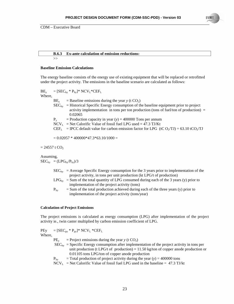
B.6.3 Ex-ante calculation of emission reductions: >>
Baseline Emission Calculations The energy baseline consists of the energy use of existing equipment that will be replaced or retrofitted under the project activity. The emissions in the baseline scenario are calculated as follows: BEy = [SECby * Pby]* NCV L*CEFL Where,
BEy = Baseline emissions during the year y (t CO2) SECby = Historical Specific Energy consumption of the baseline equipment prior to project
activity implementation in tons per ton production (tons of fuel/ton of production) = 0.02065
Py = Production capacity in year (y) = 400000 Tons per annum NCVL = Net Calorific Value of fossil fuel LPG used = 47.3 TJ/Kt CEFL = IPCC default value for carbon emission factor for LPG (tC O2/TJ) = 63.10 tCO2/TJ
= 0.02057 * 400000*47.3*63.10/1000 =
= 24557 t CO2 Assuming, SECby = (LPGby/Pby)/3
SECby = Average Specific Energy consumption for the 3 years prior to implementation of the project activity, in tons per unit production (kt LPG/t of production)
LPGby = Sum of the total quantity of LPG consumed during each of the 3 years (y) prior to implementation of the project activity (tons) Pby = Sum of the total production achieved during each of the three years (y) prior to implementation of the project activity (tons/year)
Calculation of Project Emissions
The project emissions is calculated as energy consumption (LPG) after implementation of the project activity ie., twin caster multiplied by carbon emission coefficient of LPG. PEy = [SECpy * Ppy]* NCV L *CEFL Where,
PEy = Project emissions during the year y (t CO2) SECby = Specific Energy consumption after implementation of the project activity in tons per unit production (t LPG/t of production) = 11.50 kg/ton of copper anode production or
0.01105 tons LPG/ton of copper anode production Pby = Total production of project activity during the year (y) = 400000 tons NCVL = Net Calorific Value of fossil fuel LPG used in the baseline = 47.3 TJ/kt
PROJECT DESIGN DOCUMENT FORM (CDM-SSC-PDD) - Version 03 CDM – Executive Board
24
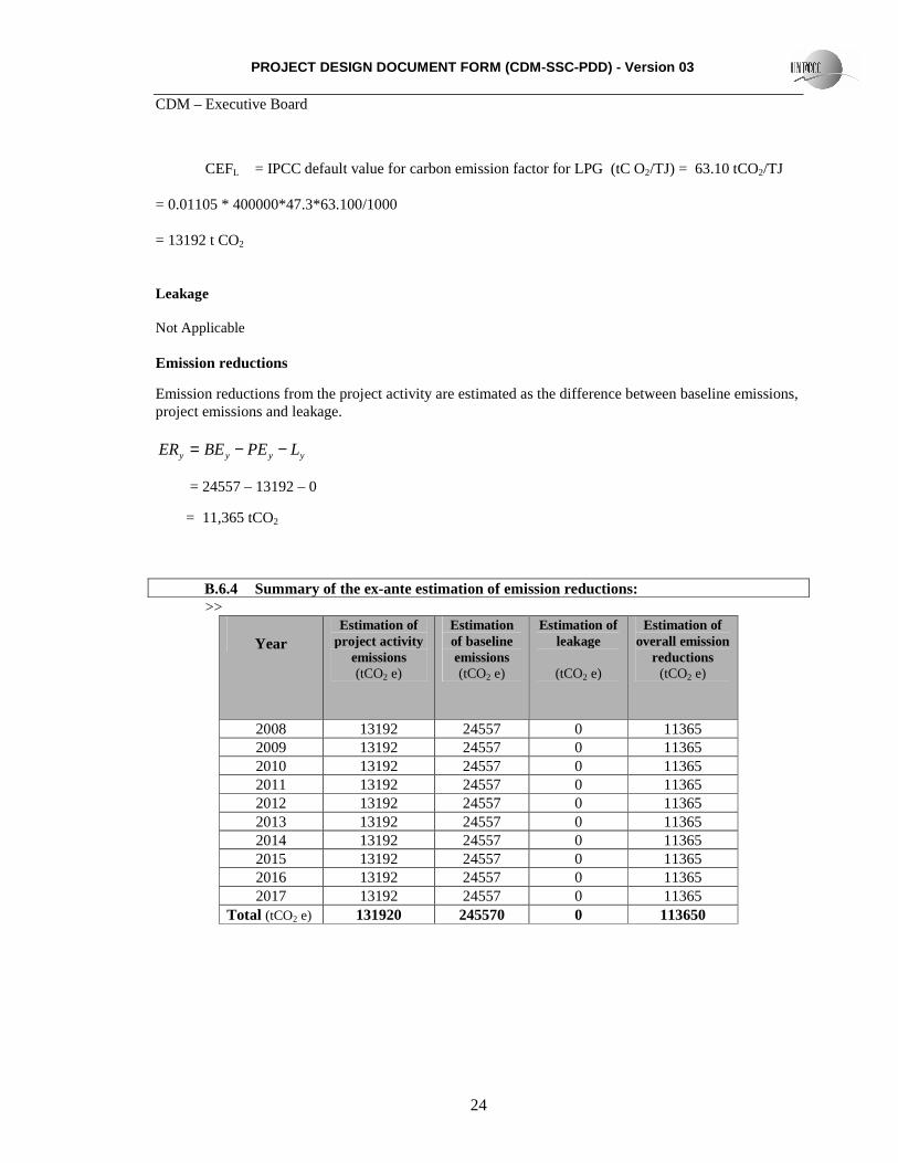
CEFL = IPCC default value for carbon emission factor for LPG (tC O2/TJ) = 63.10 tCO2/TJ = 0.01105 * 400000*47.3*63.100/1000 = 13192 t CO2
Leakage Not Applicable Emission reductions
Emission reductions from the project activity are estimated as the difference between baseline emissions, project emissions and leakage.
yyyy LPEBEER −−=
= 24557 – 13192 – 0
= 11,365 tCO2
B.6.4 Summary of the ex-ante estimation of emission reductions: >>
PROJECT DESIGN DOCUMENT FORM (CDM-SSC-PDD) - Version 03 CDM – Executive Board
25
B.7 Application of a monitoring methodology and description of the monitoring plan:
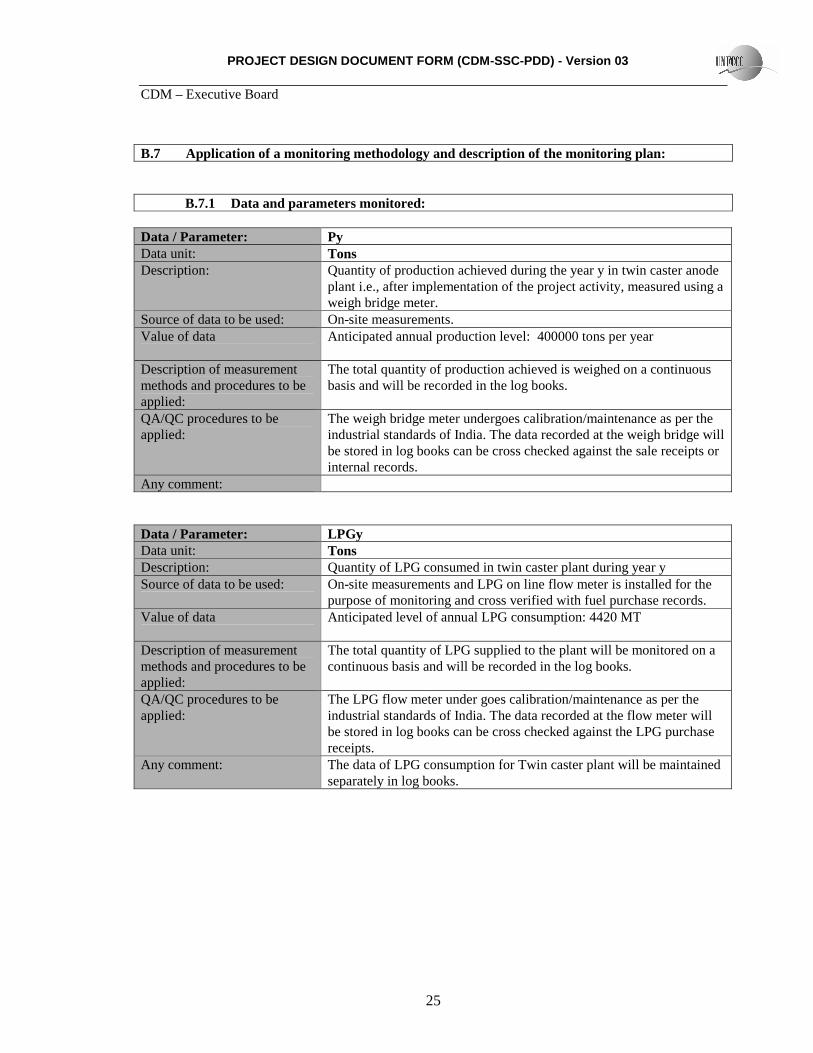
B.7.1 Data and parameters monitored:
Data / Parameter: Py Data unit: Tons Description: Quantity of production achieved during the year y in twin caster anode
plant i.e., after implementation of the project activity, measured using a weigh bridge meter.
Source of data to be used: On-site measurements. Value of data Anticipated annual production level: 400000 tons per year
Description of measurement methods and procedures to be applied:
The total quantity of production achieved is weighed on a continuous basis and will be recorded in the log books.
QA/QC procedures to be applied:
The weigh bridge meter undergoes calibration/maintenance as per the industrial standards of India. The data recorded at the weigh bridge will be stored in log books can be cross checked against the sale receipts or internal records.
Any comment:
Data / Parameter: LPGy Data unit: Tons Description: Quantity of LPG consumed in twin caster plant during year y Source of data to be used: On-site measurements and LPG on line flow meter is installed for the
purpose of monitoring and cross verified with fuel purchase records. Value of data Anticipated level of annual LPG consumption: 4420 MT
Description of measurement methods and procedures to be applied:
The total quantity of LPG supplied to the plant will be monitored on a continuous basis and will be recorded in the log books.
QA/QC procedures to be applied:
The LPG flow meter under goes calibration/maintenance as per the industrial standards of India. The data recorded at the flow meter will be stored in log books can be cross checked against the LPG purchase receipts.
Any comment: The data of LPG consumption for Twin caster plant will be maintained separately in log books.
PROJECT DESIGN DOCUMENT FORM (CDM-SSC-PDD) - Version 03 CDM – Executive Board
26
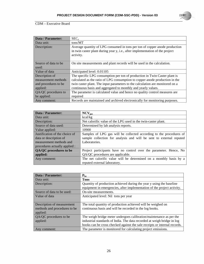
Data / Parameter: SECy Data unit: tons/MT Description: Average quantity of LPG consumed in tons per ton of copper anode production
in twin caster plant during year y, i.e., after implementation of the project activity.
Source of data to be used:
On site measurements and plant records will be used in the calculation.
Value of data Anticipated level: 0.01105 Description of measurement methods and procedures to be applied:
The specific LPG consumption per ton of production in Twin Caster plant is calculated as the ratio of LPG consumption to copper anode production in the twin caster plant. The input parameters to the calculation are monitored on a continuous basis and aggregated to monthly and yearly values.
QA/QC procedures to be applied:
The parameter is calculated value and hence no quality control measures are required
Any comment: Records are maintained and archived electronically for monitoring purposes.
Data / Parameter: NCVgas Data unit: kcal/kg Description: Net calorific value of the LPG used in the twin-caster plant. Source of data used: Determined by lab analysis reports. Value applied: 10900 Justification of the choice of data or description of measurement methods and procedures actually applied :
Samples of LPG gas will be collected according to the procedures of sample collection for analysis and will be sent to external reputed Laboratories.
QA/QC procedures to be applied:
Project participants have no control over the parameter. Hence, No QA/QC procedures are applicable.
Any comment: The net calorific value will be determined on a monthly basis by a reputed external laboratory.
Data / Parameter: Pbe Data unit: Tons Description: Quantity of production achieved during the year y using the baseline
equipment in emergencies, after implementation of the project activity. Source of data to be used: On-site measurements. Value of data Anticipated level: Nil tons per year
Description of measurement methods and procedures to be applied:
The total quantity of production achieved will be weighed on continuous basis and will be recorded in the log books.
QA/QC procedures to be applied:
The weigh bridge meter undergoes calibration/maintenance as per the industrial standards of India. The data recorded at weigh bridge in log books can be cross checked against the sale receipts or internal records.
Any comment: The parameter is monitored for calculating project emissions.
PROJECT DESIGN DOCUMENT FORM (CDM-SSC-PDD) - Version 03 CDM – Executive Board
27
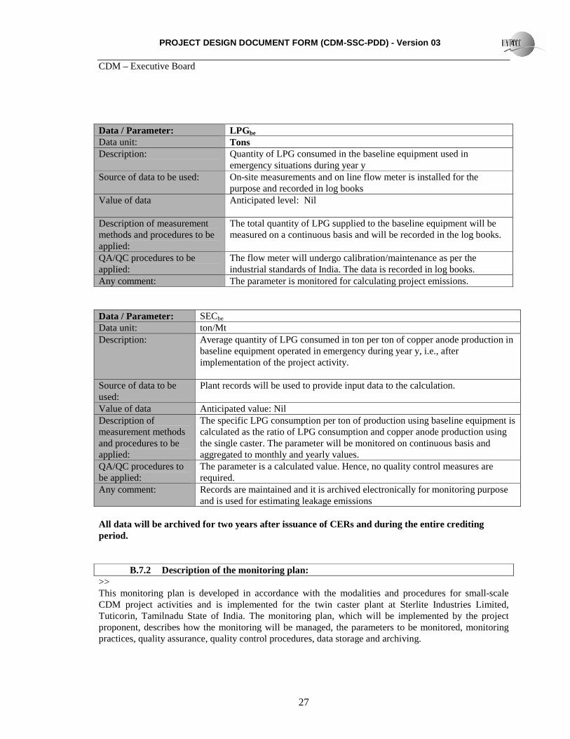
Data / Parameter: LPGbe Data unit: Tons Description: Quantity of LPG consumed in the baseline equipment used in
emergency situations during year y Source of data to be used: On-site measurements and on line flow meter is installed for the
purpose and recorded in log books Value of data Anticipated level: Nil
Description of measurement methods and procedures to be applied:
The total quantity of LPG supplied to the baseline equipment will be measured on a continuous basis and will be recorded in the log books.
QA/QC procedures to be applied:
The flow meter will undergo calibration/maintenance as per the industrial standards of India. The data is recorded in log books.
Any comment: The parameter is monitored for calculating project emissions. Data / Parameter: SECbe Data unit: ton/Mt Description: Average quantity of LPG consumed in ton per ton of copper anode production in
baseline equipment operated in emergency during year y, i.e., after implementation of the project activity.
Source of data to be used:
Plant records will be used to provide input data to the calculation.
Value of data Anticipated value: Nil Description of measurement methods and procedures to be applied:
The specific LPG consumption per ton of production using baseline equipment is calculated as the ratio of LPG consumption and copper anode production using the single caster. The parameter will be monitored on continuous basis and aggregated to monthly and yearly values.
QA/QC procedures to be applied:
The parameter is a calculated value. Hence, no quality control measures are required.
Any comment: Records are maintained and it is archived electronically for monitoring purpose and is used for estimating leakage emissions
All data will be archived for two years after issuance of CERs and during the entire crediting period.
B.7.2 Description of the monitoring plan:
>> This monitoring plan is developed in accordance with the modalities and procedures for small-scale CDM project activities and is implemented for the twin caster plant at Sterlite Industries Limited, Tuticorin, Tamilnadu State of India. The monitoring plan, which will be implemented by the project proponent, describes how the monitoring will be managed, the parameters to be monitored, monitoring practices, quality assurance, quality control procedures, data storage and archiving.
PROJECT DESIGN DOCUMENT FORM (CDM-SSC-PDD) - Version 03 CDM – Executive Board
28
Project Management The authority and responsibility for registration, monitoring, measurement, reporting and reviewing of the data rests with the CEO for Sterlite Industries India Ltd. The CEO may delegate the same to a competent person identified for the purpose. The identified person will be in charge of GHG monitoring activities and necessary reports will be submitted to the management, i.e. CEO or Committee, for review. The designated manager will be assisted by a team of experienced personnel in disciplines such as mechanical and electrical engineering with experience in plant operation, measurements and management. The primary responsibility of the team is to measure, monitor, record, and report the information on various data items to the Vice President (operations), in accordance with the applicable standards. Periodic calibration of various instruments used in the monitoring and record keeping of GHG related data will also be the responsibility of the team. The responsibility for review, storage and archiving of information in good condition lies with the designated manager. The concerned manager will undertake periodic verifications and onsite inspections to ensure the quality of the data collected by the team and initiate corrective steps in case of any abnormal conditions. The company will introduce an internal auditing system for CDM monitoring compliance. Internal auditing will be carried out as per the monitoring schedule and whenever necessary. An internal audit report will be prepared for review by the CEO, which will subsequently be submitted to an independent Designated Operational Entity (DOE) for verification. The CEO will examine the internal audit reports and will take particular note of any deviations in data over the norms, and will monitor that any corrective actions required have resulted in adherence to the standards. Monitoring Requirements The monitoring plan includes monitoring of the quantity of LPG consumed under the project activity, calorific values of LPG used, production of copper anode castings from the twin-caster plant and calculation of specific LPG consumption per ton of production in the twin-caster plant. Emission reductions resulting from the project activity will be calculated using the formulae as illuminated in Section B.6.1 of the PDD. Emission reductions generated by the project shall be monitored at regular intervals. The crediting period chosen for the project activity is 10 years. Monitoring equipment is comprised of weigh bridge meters and LPG flow meters. External laboratories will measure the calorific value of the LPG consumed. Project proponent will appoint a Designated Operational Entity (DOE) for verification of emission reductions resulting from the project activity at regular intervals.
PROJECT DESIGN DOCUMENT FORM (CDM-SSC-PDD) - Version 03 CDM – Executive Board
29
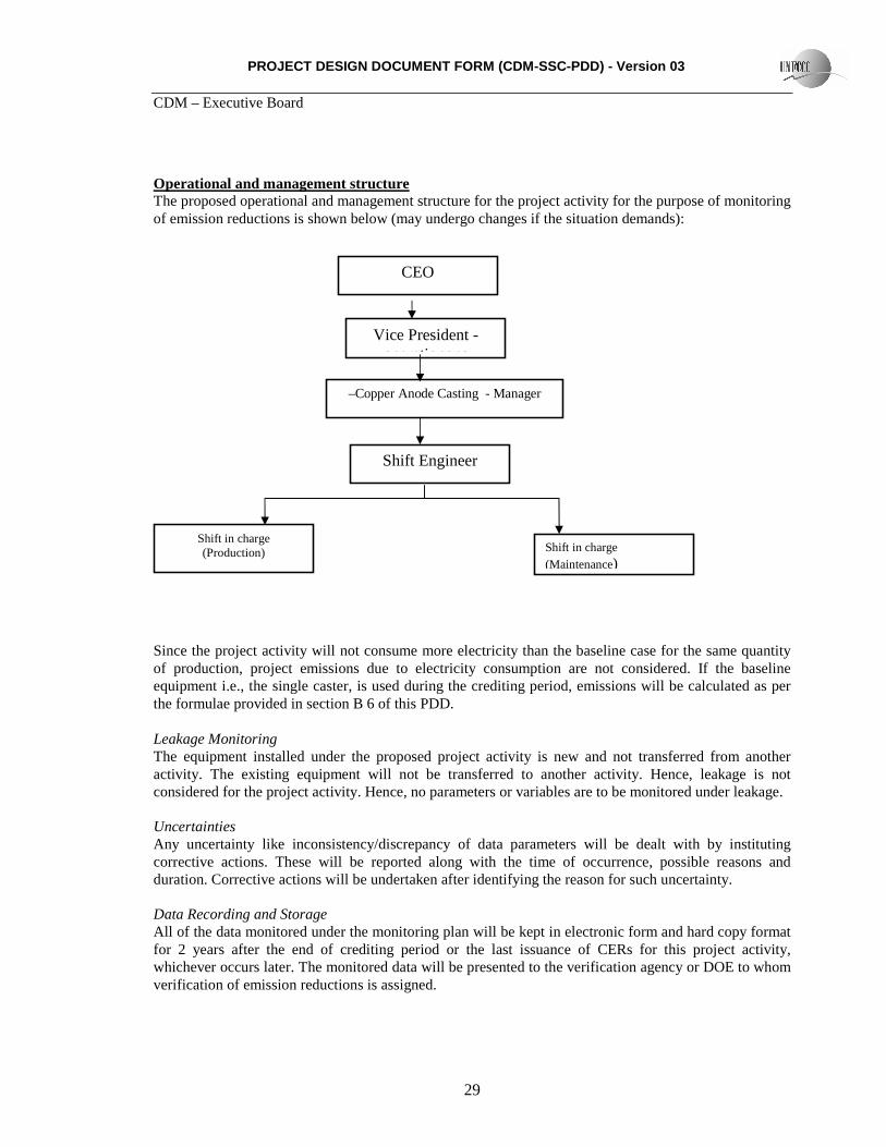
Operational and management structure The proposed operational and management structure for the project activity for the purpose of monitoring of emission reductions is shown below (may undergo changes if the situation demands):
Since the project activity will not consume more electricity than the baseline case for the same quantity of production, project emissions due to electricity consumption are not considered. If the baseline equipment i.e., the single caster, is used during the crediting period, emissions will be calculated as per the formulae provided in section B 6 of this PDD. Leakage Monitoring The equipment installed under the proposed project activity is new and not transferred from another activity. The existing equipment will not be transferred to another activity. Hence, leakage is not considered for the project activity. Hence, no parameters or variables are to be monitored under leakage. Uncertainties Any uncertainty like inconsistency/discrepancy of data parameters will be dealt with by instituting corrective actions. These will be reported along with the time of occurrence, possible reasons and duration. Corrective actions will be undertaken after identifying the reason for such uncertainty. Data Recording and Storage All of the data monitored under the monitoring plan will be kept in electronic form and hard copy format for 2 years after the end of crediting period or the last issuance of CERs for this project activity, whichever occurs later. The monitored data will be presented to the verification agency or DOE to whom verification of emission reductions is assigned.
CEO
Vice President - operationons
–Copper Anode Casting - Manager
Shift in charge (Maintenance)
Shift in charge (Production)
Shift Engineer
PROJECT DESIGN DOCUMENT FORM (CDM-SSC-PDD) - Version 03 CDM – Executive Board
30
The technology and equipment supplier has provided operating manuals, procedures and training for the SIIL personnel as per their agreement signed with the Project Participants. The operating manual provides procedures for monitoring the thermal energy generation, emergency preparedness, calibration of monitoring equipment, the company’s operation and maintenance responsibilities etc. The same will be adopted for GHG audits and will form part of the monitoring plan. Hence, no separate procedures for QA/QC are provided in this monitoring plan. B.8 Date of completion of the application of the baseline and monitoring methodology and the name of the responsible person(s)/entity(ies) >> The baseline for the project activity was constructed accordance with the indicative simplified baseline and monitoring methodologies for selected small-scale CDM project activity categories, AMS II D., Version 11, Scope 4, EB 35. As such, for the case of equipment replacement measures, the baseline consists of the energy baseline of the existing facility or sub system that is replaced. The project activity reduces LPG consumption in a copper anode casting plant by replacing a single caster with a twin caster. Hence, the simplified baseline is the energy baseline of the single caster and the baseline emissions are the quantity of LPG reduced by the project activity times the emission coefficient of LPG. IPCC default values for the emission coefficients will be used. Date of completion of the baseline : 20/03/2008 Name of the person / entity determining the baseline : Zenith Energy Services (P) Ltd.
Contact information of the above entity furnished below:
Organization: ZENITH ENERGY SERVICES (P) LTD. Street/P.O. Box, Building: 10-5-6/B, MYHOME PLAZA, MASABTANK, City: HYDERABAD State/Region: ANDHRA PRADESH Postfix/ZIP: 500028 Country: INDIA Telephone: +91 40 2337 6630, 2337 6631 FAX: +91 40 2332 2517 E-Mail: [email protected] URL: www.zenithenergy.com Represented by: Title: DIRECTOR Salutation: MR. Last Name: REDDY Middle Name: MOHAN First Name: ATTIPALLI
PROJECT DESIGN DOCUMENT FORM (CDM-SSC-PDD) - Version 03 CDM – Executive Board
31
SECTION C. Duration of the project activity / crediting period C.1 Duration of the project activity: C.1.1. Starting date of the project activity: >> 28/10/2002
C.1.2. Expected operational lifetime of the project activity: >> 30 years C.2 Choice of the crediting period and related information: C.2.1. Renewable crediting period Not chosen C.2.1.1. Starting date of the first crediting period: >> Not applicable C.2.1.2. Length of the first crediting period: >> Not applicable C.2.2. Fixed crediting period: The project proponent wishes to select the fixed crediting period C.2.2.1. Starting date: >> 01/08/08 C.2.2.2. Length: >> 10 years
PROJECT DESIGN DOCUMENT FORM (CDM-SSC-PDD) - Version 03 CDM – Executive Board
32
SECTION D. Environmental impacts >> D.1. If required by the host Party, documentation on the analysis of the environmental impacts of the project activity: >> As per the Environmental Impact Assessment (EIA) notification S.O.60 (E), dated 27/01/1994, and subsequent amendments to the notification until 2002, the project falls under category 19 (Thermal Power Plants) of Schedule – I. As per Clause 3.b of the notification, projects under category 19 need not obtain/conduct any environmental clearance and Environmental Impact Assessment, if the investment is less than Rs. 1000 millions. Since the total cost of the project activity is Rs. 100 millions, the project activity does not call for an EIA. However, the project activity is required to obtain permission from the Tamilnadu State Pollution Control Board for implementing the project activity. The project proponents have obtained necessary clearance in this regard and will be made available for the validator. There is no negative impact on the environment due to project activity either during the installation phase or post project implementation.
D.2. If environmental impacts are considered significant by the project participants or the host Party, please provide conclusions and all references to support documentation of an environmental impact assessment undertaken in accordance with the procedures as required by the host Party: >> No significant impacts are possible as a result of project implementation. Hence not applicable. SECTION E. Stakeholders’ comments >> E.1. Brief description how comments by local stakeholders have been invited and compiled: >> Identification of Stakeholders The project activity involves the installation of a twin caster wheel in order to reduce LPG consumption in copper anode production. It is relatively small scale with no significant negative impacts such as noise, air or water pollution outside the plant facility. Therefore, comments from the local population are not necessary. However, the stakeholders listed below have been identified. They include government and non-government parties, which have been involved in the project activity at various stages. - SIIL Employees and Statutory Bodies like, Tamil Nadu Pollution Control Board (TNPCB) SIIL communicated all relevant information to the stakeholders listed above.
PROJECT DESIGN DOCUMENT FORM (CDM-SSC-PDD) - Version 03 CDM – Executive Board
33
The SIIL Copper Anode Casting Plant engineer presented the project activity to the project team, which is comprised of all employees of the twin caster copper anode production section. The twin caster plant operators and other shop flow employees provided complete support. E.2. Summary of the comments received: >> Stakeholders Involvement SIIL Employees: One of the most important stakeholders of the project activity is the employees of SIIL. The project activity has positive environmental impacts locally as well as globally by reducing fossil fuel consumption in copper anode production and reducing GHG emissions. SIIL employees appreciated their management’s contribution towards energy conservation and reducing greenhouse-gas emissions, which contribute to global warming. Tamil Nadu Pollution Control Board: As mentioned above, the Tamil Nadu Pollution Control Board (TNPCB) does not require SIIL to submit an Environmental Impact Assessment for the project activity. However SIIL is required to send a communication to the pollution control authorities about any major modification in their facilities. SIIL has provided the TNPCB authorities with the project activity details for their information. No comments have been received from them. E.3. Report on how due account was taken of any comments received: >> The project activity has received positive comments from the stakeholders. The CDM-PDD will be posted on the UNFCCC or validator’s web site for public viewing and comments.
PROJECT DESIGN DOCUMENT FORM (CDM-SSC-PDD) - Version 03 CDM – Executive Board
34
Annex 1
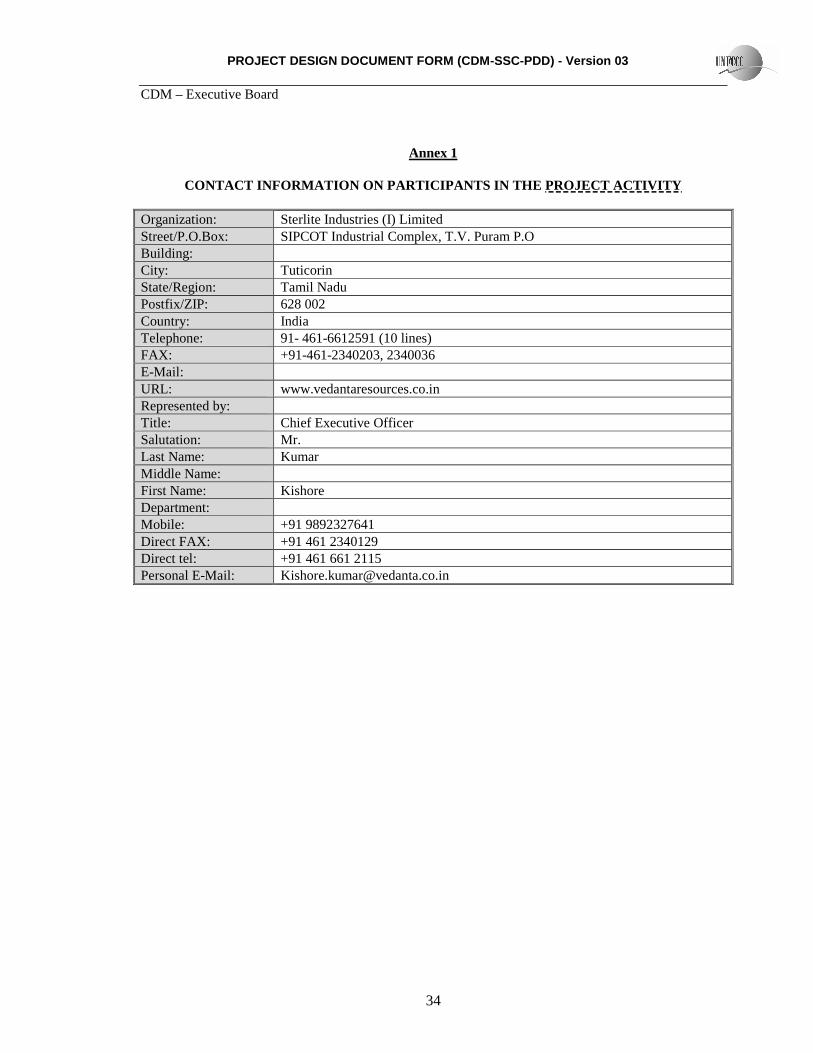
CONTACT INFORMATION ON PARTICIPANTS IN THE PROJECT ACTIVITY Organization: Sterlite Industries (I) Limited Street/P.O.Box: SIPCOT Industrial Complex, T.V. Puram P.O Building: City: Tuticorin State/Region: Tamil Nadu Postfix/ZIP: 628 002 Country: India Telephone: 91- 461-6612591 (10 lines) FAX: +91-461-2340203, 2340036 E-Mail: URL: www.vedantaresources.co.in Represented by: Title: Chief Executive Officer Salutation: Mr. Last Name: Kumar Middle Name: First Name: Kishore Department: Mobile: +91 9892327641 Direct FAX: +91 461 2340129 Direct tel: +91 461 661 2115 Personal E-Mail: [email protected]
PROJECT DESIGN DOCUMENT FORM (CDM-SSC-PDD) - Version 03 CDM – Executive Board
35
Annex 2
INFORMATION REGARDING PUBLIC FUNDING
No public funding is envisaged from countries listed in Annex 1 of Kyoto Protocol
PROJECT DESIGN DOCUMENT FORM (CDM-SSC-PDD) - Version 03 CDM – Executive Board
36
Annex 3
BASELINE INFORMATION
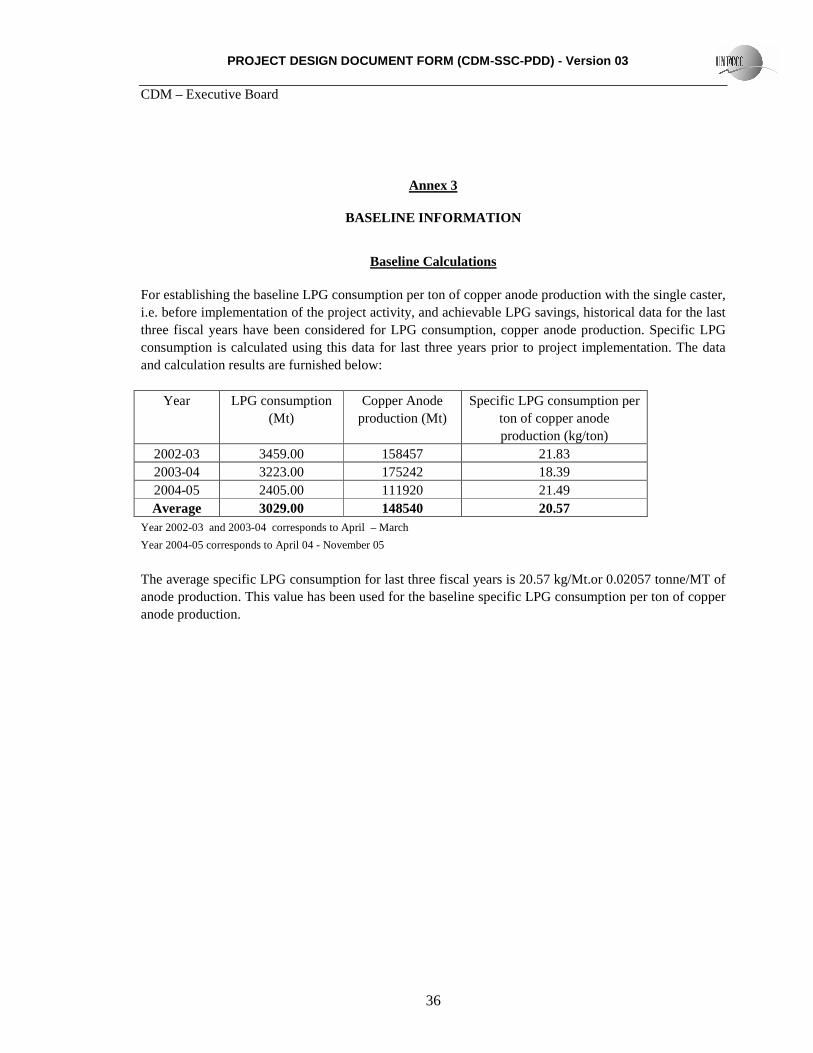
Baseline Calculations For establishing the baseline LPG consumption per ton of copper anode production with the single caster, i.e. before implementation of the project activity, and achievable LPG savings, historical data for the last three fiscal years have been considered for LPG consumption, copper anode production. Specific LPG consumption is calculated using this data for last three years prior to project implementation. The data and calculation results are furnished below:
Year LPG consumption (Mt)
Copper Anode production (Mt)
Specific LPG consumption per ton of copper anode production (kg/ton)
Year 2002-03 and 2003-04 corresponds to April – March
Year 2004-05 corresponds to April 04 - November 05
The average specific LPG consumption for last three fiscal years is 20.57 kg/Mt.or 0.02057 tonne/MT of anode production. This value has been used for the baseline specific LPG consumption per ton of copper anode production.
PROJECT DESIGN DOCUMENT FORM (CDM-SSC-PDD) - Version 03 CDM – Executive Board
37
Annex 4
MONITORING INFORMATION
As provided in section B.7.2 of the PDD
PROJECT DESIGN DOCUMENT FORM (CDM-SSC-PDD) - Version 03 CDM – Executive Board
38
Attachment 1
Calculation for TJ to GWh conversion
1 TJ = 0.2777 GWh
1GWh = 109 Watt hour
1 GWh = 109 *Joule/second * 3600 seconds
= 3600 * 109 *Joule
= 3.6 * 1012 Joule
1 GWh = 3.6 TJ
1 TJ = 1/3.6 GWh
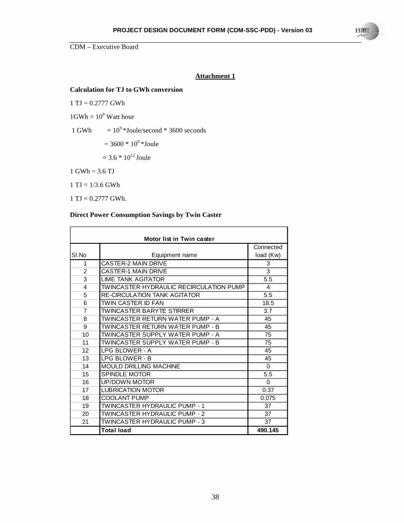
1 TJ = 0.2777 GWh. Direct Power Consumption Savings by Twin Caster
Sl.No Equipment nameConnected load (Kw)
1 CASTER-2 MAIN DRIVE 32 CASTER-1 MAIN DRIVE 33 LIME TANK AGITATOR 5.54 TWINCASTER HYDRAULIC RECIRCULATION PUMP 45 RE-CIRCULATION TANK AGITATOR 5.56 TWIN CASTER ID FAN 18.57 TWINCASTER BARYTE STIRRER 3.78 TWINCASTER RETURN WATER PUMP - A 459 TWINCASTER RETURN WATER PUMP - B 4510 TWINCASTER SUPPLY WATER PUMP - A 7511 TWINCASTER SUPPLY WATER PUMP - B 7512 LPG BLOWER - A 4513 LPG BLOWER - B 4514 MOULD DRILLING MACHINE 015 SPINDLE MOTOR 5.516 UP/DOWN MOTOR 017 LUBRICATION MOTOR 0.3718 COOLANT PUMP 0.07519 TWINCASTER HYDRAULIC PUMP - 1 3720 TWINCASTER HYDRAULIC PUMP - 2 3721 TWINCASTER HYDRAULIC PUMP - 3 37
Total load 490.145
Motor list in Twin caster
PROJECT DESIGN DOCUMENT FORM (CDM-SSC-PDD) - Version 03 CDM – Executive Board
39
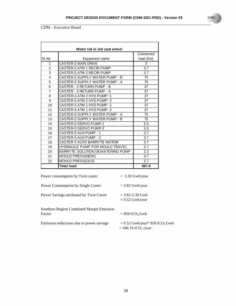
Sl.No Equipment nameConnected load (Kw)
1 CASTER-3 MAIN DRIVE 32 CASTER-3 ATM 1 RECIR.PUMP 3.73 CASTER-3 ATM 2 RECIR.PUMP 3.74 CASTER-3 SUPPLY WATER PUMP - B 755 CASTER-3 SUPPLY WATER PUMP - A 756 CASTER - 3 RETURN PUMP - B 377 CASTER - 3 RETURN PUMP - A 378 CASTER-3 ATM 2 HYD PUMP -1 379 CASTER-3 ATM 2 HYD PUMP -2 3710 CASTER-3 ATM 1 HYD PUMP -1 3711 CASTER-3 ATM 1 HYD PUMP -2 3712 CASTER-3 SUPPLY WATER PUMP - A 7513 CASTER-3 SUPPLY WATER PUMP - B 7514 CASTER-3 SERVO PUMP-1 5.515 CASTER-3 SERVO PUMP-2 5.516 CASTER-3 AUX PUMP - 1 3.717 CASTER-3 AUX PUMP - 2 3.718 CASTER 3 AUTO BARRYTE MOTOR 3.719 HYDRAULIC PUMP FOR MOULD TRAVEL 3.720 BARRYTE SOLUTION DEWATERING PUMP 2.221 MOULD PRESS(NEW) 3.722 MOULD PRESS(OLD) 3.7
Total load 567.8
Motor list in old cast wheel
Power consumption by Twin caster = 3.30 Gwh/year Power Consumption by Single Caster = 3.82 Gwh/year Power Savings attributed by Twin Caster = 3.82-3.30 Gwh = 0.52 Gwh/year Southern Region Combined Margin Emission Factor = 858 tCO2/Gwh Emission reductions due to power savings = 0.52 Gwh/year* 858 tCO2/Gwh = 446.16 tCO2 /year.
PROJECT DESIGN DOCUMENT FORM (CDM-SSC-PDD) - Version 03 CDM – Executive Board
40
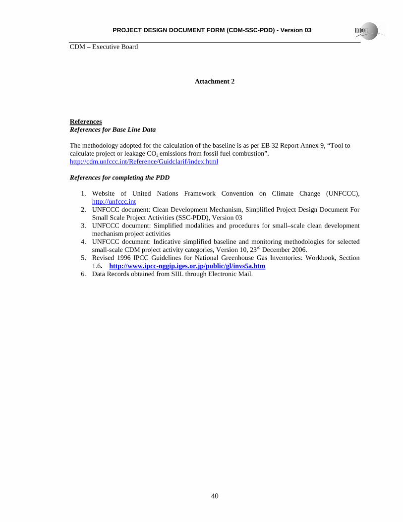
Attachment 2 References References for Base Line Data The methodology adopted for the calculation of the baseline is as per EB 32 Report Annex 9, “Tool to calculate project or leakage CO2 emissions from fossil fuel combustion”. http://cdm.unfccc.int/Reference/Guidclarif/index.html References for completing the PDD
1. Website of United Nations Framework Convention on Climate Change (UNFCCC),
http://unfccc.int 2. UNFCCC document: Clean Development Mechanism, Simplified Project Design Document For
Small Scale Project Activities (SSC-PDD), Version 03 3. UNFCCC document: Simplified modalities and procedures for small–scale clean development
mechanism project activities 4. UNFCCC document: Indicative simplified baseline and monitoring methodologies for selected
small-scale CDM project activity categories, Version 10, 23rd December 2006. 5. Revised 1996 IPCC Guidelines for National Greenhouse Gas Inventories: Workbook, Section
1.6. http://www.ipcc-nggip.iges.or.jp/public/gl/invs5a.htm 6. Data Records obtained from SIIL through Electronic Mail.
PROJECT DESIGN DOCUMENT FORM (CDM-SSC-PDD) - Version 03 CDM – Executive Board
41
Attachment 3
Abbreviations
CEA Central Electricity Authority
CO2 Carbon dioxide
EIA Environment Impact Assessment
GHG Greenhouse gas
GoI Government of India
GWh Giga Watt hour
IPCC Inter Governmental Panel On Climate Change
kWh Kilo watt hour
LPG Liquefied Petroleum Gas
MoEF Ministry of Environmental and Forestry
PDD Project Design Document
SIIL Sterlite Industries India Limited
TNPCB Tamil Nadu Pollution Control Board
TNEB Tamil Nadu Electricity Board
UNFCCC United Nations Framework Convention on Climate Change