126
STERRAD ® NX ™ Sterilization System Service Troubleshooting Guide
STERRAD® NX™ Sterilization System Service Troubleshooting Guide
STERRAD® NX™ Sterilization System Service Troubleshooting
Guide
1-888-STERRAD (1-888-783-7723) ASP USA Customer Care Center
www.sterrad.com International Technical Support 001.949.581.5799
ASP International Customer Support (Call your local ASP Customer Support Representative)
© 2005. Advanced Sterilization Products. All rights reserved. Other products mentioned in this publication are trademarked by their respective owners. Reproduction, adaptation, or translation of this publication
without prior written permission is prohibited. Printed in the U.S.A.
08-53528-0-001 TS-53527-0-001 Rev A
2 STERRAD® NX™ Service Guide
Contents Chapter 1. Introduction 7
Overview ...........................................................................................................................................7 Sterilant and Cassette.........................................................................................................................8 Hardware ...........................................................................................................................................8 Software.............................................................................................................................................8
Chapter 2. Safety Information 11 Personal Safety and First Aid ............................................................................................................11
Cassette Handling ........................................................................................................................13 Personal Protection Equipment..........................................................................................................13 Warnings, Cautions, and Notes..........................................................................................................14 Symbols Used on the Sterilizer and in This Guide ............................................................................14 Safety Standards Compliance ............................................................................................................15
Chapter 3. Functional Description 17 Overview of the Sterilization Process................................................................................................17 Hydrogen Peroxide Concentration and Delivery ...............................................................................18 Process Monitoring and Control ........................................................................................................18
Temperature .................................................................................................................................19 Pressure........................................................................................................................................19 Hydrogen Peroxide Monitor ........................................................................................................19 Plasma Power...............................................................................................................................20 Time .............................................................................................................................................20
System Software ................................................................................................................................20 Functional Block Diagram.................................................................................................................22 Subsystems ........................................................................................................................................23
Hydrogen Peroxide Delivery Subsystem .....................................................................................23 Vaporization Subsystem ..............................................................................................................23 Vacuum Subsystem......................................................................................................................23 Plasma Subsystem........................................................................................................................23 Hydrogen Peroxide Monitor Subsystem ......................................................................................23
Modular Design .................................................................................................................................24 Modules and Subsystem Details ..................................................................................................25
Top Module .......................................................................................................................................27 Chassis .........................................................................................................................................27 Access Panels...............................................................................................................................28 Display Assembly ........................................................................................................................28 Cassette Drawer ...........................................................................................................................28 Delivery System...........................................................................................................................28 Vaporizer/Condenser ...................................................................................................................28 Power Inlet Connector .................................................................................................................28 AC Distribution............................................................................................................................29 DC Power Supply ........................................................................................................................29 System Controller ........................................................................................................................29 Fan ...............................................................................................................................................29
Chamber Module ...............................................................................................................................30 Access Panels...............................................................................................................................30 Door Assembly ............................................................................................................................30 Chamber and Shelves...................................................................................................................31 Electrode ......................................................................................................................................31
STERRAD® NX™ Service Guide 3
Feedthrough................................................................................................................................. 31 Base Module ..................................................................................................................................... 32
Frame and Chassis....................................................................................................................... 33 Access Panel................................................................................................................................ 33 Circuit Breaker ............................................................................................................................ 33 LFPS II Power Supply................................................................................................................. 33 Printer.......................................................................................................................................... 33 Vacuum Pump Assembly ............................................................................................................ 33
Diagnostic Functions and Tests ........................................................................................................ 34 Subsystems and Components ...................................................................................................... 34 Door Heater Resistance Configuration........................................................................................ 36
Process Variables and Cancellation Limits ....................................................................................... 37 Chapter 4. Diagnostic Tests and Error Messages 39
Diagnostic Files ................................................................................................................................ 39 Diagnostics........................................................................................................................................ 39
Diagnostic Tests .......................................................................................................................... 40 Troubleshooting ................................................................................................................................ 42
Error Messages............................................................................................................................ 42 Diagnostic Messages ................................................................................................................... 47
Chapter 5. Subassembly Removal and Replacement 53 Access to Sterilizer Interior............................................................................................................... 53
Front Top Panel (02-51326) ........................................................................................................ 54 Top Panel (33-51196).................................................................................................................. 55 Rear Top Panel (33-51197) ......................................................................................................... 56 Front Bottom Panel (33-51195) .................................................................................................. 57 Right Side Panel (33-51193) ....................................................................................................... 58 Left Side Panel (33-51193) ......................................................................................................... 59 Door Cover (33-51993) ............................................................................................................... 60
Top Module....................................................................................................................................... 61 Delivery System Assembly (02-51984) ...................................................................................... 61 Delivery Valve ............................................................................................................................ 63 Delivery Subsystem Inlet Filter (PM kit part 25-50703)............................................................ 63 Air Pump Tubes .......................................................................................................................... 63 Vaporizer/Condenser Assembly (02-52410) ............................................................................... 64 Vent Valve (28-51218)................................................................................................................ 66 Chamber Pressure Control Assembly (02-52387)....................................................................... 68 Circuit Boards Assembly: Universal Control Board (UCB) (04-50361) and Interface Board (04-52006) ......................................................................................................................................... 70 Alternating Current (AC) Distribution Assembly (02-51959) .................................................... 72 Direct Current (DC) Power Supply (40-51141) .......................................................................... 74 Display Assembly (40-50532)..................................................................................................... 76 Fan Assembly (04-51991) ........................................................................................................... 78 Door Lock Solenoid (42-52001) and Door Lock Sensor (04-51990)......................................... 79 Power Inlet Connector (45-51407).............................................................................................. 80 Ultraviolet Lamp Power Supply (40-51449) ............................................................................... 81 Hydrogen Peroxide Monitor Lamp Assembly (04-50544).......................................................... 82
Chamber Module .............................................................................................................................. 84 Electrode Assembly (03-51157) Spacers and Slides (35-51152), Lower Shelf Stop (35-51153), Upper Shelf Stop (33-51158) ...................................................................................................... 84 Door Assembly (03-51985)......................................................................................................... 85 Door Seal O-Ring (22-00537) ..................................................................................................... 87 Latch Assembly (74-51398)........................................................................................................ 88
4 STERRAD® NX™ Service Guide
..............................................................................................................
Hydrogen Peroxide Detector Assembly (04-52108) ....................................................................89 Base Module ......................................................................................................................................90
Vacuum Pump Assembly (04-52158) ..........................................................................................90 Catalytic Converter (25-05611) ...................................................................................................92 Catalytic Converter (25-05611) ...................................................................................................92 Oil Mist Filter (25-51970)............................................................................................................93 Vacuum Control Valve (28-51216) .............................................................................................94 Oil Return Valve (28-51971) .......................................................................................................95 Low Frequency Plasma System (LFPS II) (40-52154) ................................................................96 Printer Assembly (04-51482).......................................................................................................97 Circuit Breaker (57-52105) ..........................................................................................................99
Chapter 6. Planned Maintenance 101 Overview ...........................................................................................................................................101 Vacuum Pump Oil Replacement........................................................................................................102 Catalytic Converter Replacement ......................................................................................................103 Oil Mist Filter Replacement ..............................................................................................................103 Air Filter Replacement.......................................................................................................................103 Vent Valve HEPA Filter Replacement ..............................................................................................103 Hydrogen Peroxide Detector Lamp ...................................................................................................104 Delivery Subsystem Inlet Filter Replacement ...................................................................................105 Air Pump Tubes Replacement ...........................................................................................................105 Door Seal O-Ring Replacement ........................................................................................................106 Chamber/Electrode/Plastics ...............................................................................................................107 Thermistor Replacement....................................................................................................................107
Chamber Thermistor Replacement...............................................................................................107 Door Thermistor Replacement.....................................................................................................108 Condenser/Vaporizer Thermistors Replacement..........................................................................109
Cassette Disposal and Printer Maintenance .......................................................................................109 Replacing a Cassette Disposal Box..............................................................................................110 Inserting a New Cassette Disposal Box .......................................................................................110 Cleaning the Thermal Printer Head..............................................................................................111 Replacing the Printer Paper..........................................................................................................112
STERRAD® NX™ Service Guide 5
Chapter 7. System Calibration and Verification 115 Overview........................................................................................................................................... 115 Service Action Table......................................................................................................................... 115 Zeroing Pressure Transducers ........................................................................................................... 116 Leak Test........................................................................................................................................... 117 Plasma Power Delivery Verification................................................................................................. 118 Temperature Calibration Using A Temperature Bath or Precision Resistors.................................... 119 Peroxide Calibration With Neutral Density Filters ........................................................................... 122
Diagnostics .................................................................................................................................. 123 Temperature Verification.................................................................................................................. 123
Appendix A. STERRAD® NX™ Sterilizer Specifications 125
6 STERRAD® NX™ Service Guide
Introduction 1
Chapter 1.
Introduction
Overview The STERRAD® NX™ Sterilizer is a self-contained stand-alone system of hardware and software designed to sterilize medical instruments and devices using a patented hydrogen peroxide gas plasma process. Hydrogen peroxide vapor is generated by delivering aqueous hydrogen peroxide into the vaporizer where the solution is heated and vaporized. The hydrogen peroxide vapor is then introduced into the sterilization chamber, under sub-ambient pressure, where it is transformed into a gas-plasma by use of electrical energy.
The STERRAD NX Sterilizer is designed for low temperature sterilization of both metal and nonmetal medical devices. Because the cycle operates within a dry environment and at low temperatures, it is especially suitable for instruments sensitive to heat and moisture.
The STERRAD NX Sterilizer employs a modified method of delivering hydrogen peroxide to sterilize devices within the sterilization chamber. This modified process concentrates the 59% hydrogen peroxide to 90% nominal hydrogen peroxide (by selectively vaporizing and removing water) prior to being transferred into the sterilization chamber.
In addition, by using the concentrated hydrogen peroxide solution, the sterilization cycle times have been reduced.
STERRAD® NX™ Service Guide 7
1 Introduction
Sterilant and Cassette The sterilant used in the STERRAD NX Sterilizer is hydrogen peroxide. It is supplied in cassette form as a separate accessory.
The cassette shell is made of white, high impact polystyrene. Each cassette encapsulates 10 individually sealed cells. Each of the filled cells of the cassette contains 1800 µl (±50 µl) of 59% nominal hydrogen peroxide. Each sterilization cycle uses two cells; therefore, a cassette can process five sterilization cycles.
Hardware The hardware for the sterilizer consists of a sterilization chamber and a variety of instruments and components which are housed in a covered frame. The sterilizer system also uses accessories such as a disposable sterilant cassette, reusable instrument trays, printer paper, and an optional movable cart. The STERRAD NX Sterilizer can be placed directly on a table, counter top, or on the movable cart.
Software The sterilization process is controlled automatically by software. The software controls and monitors the hardware through digital and analog signals. Functions managed by software include:
♦ Time
♦ Temperature/pressure measurement and control.
♦ Sterilant delivery and vaporization.
♦ Plasma power generation and measurement.
♦ Hydrogen peroxide monitor
♦ Access to chamber through lock-controlled door.
8 STERRAD® NX™ Service Guide
Introduction 1
Each parameter is part of a control loop in which information flows as input from one of many sensors to the computer, where it is processed and triggers an output signal which flows from the computer to an output device. Through this system of feedback signals (input), analysis, and response signals (output), the computer controls the entire sterilization process. If any process parameter falls outside allowable ranges, the software will cancel the cycle.
4 Note: The hydrogen peroxide monitor does not provide feedback control to the sterilizer. However, the monitor will cancel the cycle if the area under the hydrogen peroxide concentration-time curve or hydrogen peroxide rate constant does not meet specifications.
STERRAD® NX™ Service Guide 9

Safety Information 2
Chapter 2.
Safety Information
Your safety is of primary concern to Advanced Sterilization Products. This chapter provides information on safely servicing the STERRAD® NX Sterilizer. You must read and understand the safety information in this chapter before performing service on the sterilizer. Always pay attention to the warnings, cautions and notes throughout this Service Guide.
Personal Safety and First Aid
WARNING! HYDROGEN PEROXIDE IS CORROSIVE. Concentrated hydrogen peroxide is corrosive to skin, eyes, nose, throat, lungs, and the gastrointestinal tract. Always wear latex, PVC (vinyl), or nitrile gloves while removing items from the sterilizer following a cancelled cycle. Following a cancelled cycle, if items in the load show any visible moisture or liquid, hydrogen peroxide may be present.
WARNING! HYDROGEN PEROXIDE IS AN OXIDIZER. Avoid allowing hydrogen peroxide to contact organic materials, including paper, cotton, wood, or lubricants. Concentrated hydrogen peroxide is a strong oxidizer and may react with organic materials, causing ignition and fire.
WARNING! RISK OF EYE INJURY. Direct hydrogen peroxide contact with eyes can cause irreversible tissue damage. If contact with eyes occurs, immediately flush with large amounts of water. Consult a physician immediately.
WARNING! RISK OF SKIN INJURY. Direct hydrogen peroxide contact with the skin can cause severe irritation. If skin contact occurs, immediately flush with large amounts of water. If symptoms are severe or persist, consult a physician immediately.
WARNING! RISK OF RESPIRATORY IRRITATION. Inhalation of hydrogen peroxide mist can cause severe irritation of lungs, throat, and nose. If inhalation occurs, move to fresh air. Consult a physician immediately.
STERRAD® NX™ Service Guide 11
2 Safety Information
WARNING! CONCENTRATED HYDROGEN PEROXIDE IS TOXIC. Ingestion of hydrogen peroxide may be life-threatening. If swallowed, drink plenty of water immediately to dilute. Do not induce vomiting. Consult a physician immediately.
WARNING! HOT SURFACES. Components in the interior of the sterilizer may be hot. Do not touch the inside of the chamber or door with your bare or gloved hands when the sterilizer is operating. Allow the sterilizer to cool before touching interior surfaces.
CAUTION: AVOID EXPOSURE TO ULTRAVIOLET LIGHT. The hydrogen peroxide monitor uses an ultraviolet light source located inside the chamber behind the door. To avoid eye injury, do not stare directly at the ultraviolet light source for an extended period of time. Use protective eyewear if necessary.
WARNING! ELECTRIC SHOCK HAZARD. High voltages are present inside the sterilizer. Contact with electrically energized parts can cause injury or death. Turn OFF and unplug the sterilizer before performing service tasks.
12 STERRAD® NX™ Service Guide
Safety Information 2
Cassette Handling
STERRAD CASSETTES CONTAIN CONCENTRATED HYDROGEN PEROXIDE, A STRONG OXIDIZER. CONCENTRATED HYDROGEN PEROXIDE IS CORROSIVE TO SKIN, EYES, NOSE, THROAT, LUNGS, AND GASTROINTESTINAL TRACT. Direct contact with the skin can cause severe irritation. If skin contact occurs, immediately flush with large amounts of water. If symptoms are severe or persist, consult a physician immediately. Direct contact with eyes can cause irreversible tissue damage. If eye contact occurs, immediately flush with large amounts of water and immediately consult a physician. Inhalation of vapor or mist can cause severe irritation of lungs, throat, and nose. If inhalation occurs, move to fresh air and consult a physician immediately. Ingestion can produce corrosion that may be life threatening. If swallowed, immediately drink plenty of water to dilute. Do not induce vomiting. Consult a physician.
Do not remove the plastic wrapper from the cassette package if the indicator strip is red. Red indicates that the cassette might have been damaged. Call your ASP representative for credit.
Do not remove used cassettes from the cassette collection box. Dispose of the sealed cassette collection box according to local waste regulations. Cassettes with unused hydrogen peroxide are hazardous waste as defined by the Environmental Protection Agency (USA) and should be disposed of accordingly. If it is necessary to handle a used cassette, wear latex, PVC (vinyl), or nitrile gloves. Do not touch gloves to face or eyes.
Empty or expired cassettes must be replaced prior to starting the cycle as directed by a message on the sterilizer display. Cassettes with unused hydrogen peroxide are hazardous waste as defined by the Environmental Protection Agency (USA) and should be disposed of accordingly.
Personal Protection Equipment
Wear latex, PVC (vinyl), or nitrile gloves whenever handling a load after a cycle cancellation. Hydrogen peroxide liquid may be present on the load or in the chamber.
STERRAD® NX™ Service Guide 13
2 Safety Information
Warnings, Cautions, and Notes
Warnings and cautions are accompanied by symbols surrounded by a triangle and are printed in the text in bold. Warnings indicate events or conditions that can result in serious injury or death. Cautions indicate events or conditions that can result in severe damage to the equipment.
4 Notes are printed in italics and have a checkmark in front of the word “Note.” Notes highlight specific information about the proper use and maintenance of the STERRAD® NX™ Sterilization System.
Symbols Used on the Sterilizer and in This Guide
Hot surfaces present. Do not touch without protection.
Hazardous chemical present. Use personal protective equipment.
Toxic chemical present. Avoid exposure, contact, or ingestion.
Ultraviolet (UV) light hazard. Do not look at the light without UV eye protection.
High voltage hazard.
I/O On/Off.
Alternating current.
14 STERRAD® NX™ Service Guide
Safety Information 2
Safety Standards Compliance The STERRAD® NX™ Sterilizer meets the following safety standards:
♦ CAN/CSA-C22.2 No. 1010.1B: 1997; Safety Requirements for Electrical Equipment for Measurement, Control, and Laboratory Use.
♦ UL 61010A-1: 2002; Standard for Safety for Electrical Equipment for Laboratory Use.
♦ EN 61010-1: 2001; Safety Requirements for Electrical Equipment for Measurement, Control, and Laboratory Use.
♦ EN 61010-1-2: 2001; Medical Electrical Equipment, Part 1: General Requirements for Safety, Section 2: Collateral Standard: Electromagnetic Compatibility.
♦ IEC 60601-1-2; Medical Electrical Equipment. Part 1-2 General Requirements For Safety. Collateral standard: Electromagnetic Compatibility.
STERRAD® NX™ Service Guide 15


Functional Description 3
Chapter 3.
Functional Description
Overview of the Sterilization Process
The STERRAD® NX™ Sterilizer software interfaces with the hardware through digital/analog input and output signals and through serial communications via serial ports. The inputs monitor the sterilization process while the outputs control the process. The process occurs as follows:
1. The items to be sterilized are placed in the sterilization chamber, the chamber door is closed, and a vacuum pump reduces the pressure in the chamber.
2. A 59% aqueous solution of hydrogen peroxide is injected into the delivery system condenser where it is condensed and concentrated and then introduced into the chamber.
3. A low frequency electric current is delivered to the chamber electrode, causing the formation of a low temperature gas plasma in the chamber.
4. In the plasma state, the hydrogen peroxide vapor breaks apart into reactive molecules that include free radicals.
5. The combined use of hydrogen peroxide and plasma safely and rapidly sterilizes most medical instruments and materials without leaving toxic residues.
STERRAD® NX™ Service Guide 17
3 Functional Description
Hydrogen Peroxide Concentration and Delivery
During the hydrogen peroxide delivery step, hydrogen peroxide solution is delivered into the vaporizer bowl at atmospheric pressure conditions. Air is removed from the chamber and from the vaporizer/condenser by pulling a vacuum to a controlled pressure in the vaporizer/condenser. At this time, the transfer valve is closed. Water is removed from the 59% hydrogen peroxide solution by reducing the pressure in the condenser. The pressure differential between the chamber and the condenser creates the driving force to remove the water. During this concentration step, the flow of water vapor is restricted by an orifice between the condenser and the chamber, creating lower chamber pressure.
Once the controlled pressure is achieved in the condenser, the chamber pressure is further reduced by closing the orifice with the transition valve. The condenser temperature is increased and the concentrated hydrogen peroxide vapor is then transferred into the chamber by opening the transfer valve and the transition valve. This transfer step is followed by the diffusion step (which occurs at atmospheric pressure), followed by pressure reduction and plasma. The vent step then occurs which returns the chamber to atmospheric pressure. This process occurs twice during a complete sterilization cycle.
Process Monitoring and Control The monitoring and control systems regulate the following:
♦ Temperature
♦ Pressure
♦ Hydrogen peroxide monitor
♦ Plasma power
♦ Time
♦ Process status
♦ IMS
18 STERRAD® NX™ Service Guide
Functional Description 3
Temperature Temperature monitoring and control are involved in two aspects of the STERRAD NX Process: heating and cooling of the condenser that condenses hydrogen peroxide during vaporization, and heating the vaporizer, chamber walls and door. The temperature control loop consists of heaters and temperature sensors. There are five temperature sensors in the system. The are located on the vaporizer, condenser, door, chamber front, and chamber rear.
Pressure Pressure monitoring and control are performed by a control loop which includes the vacuum pump, vacuum control valve, vent valve, three pressure transducers and an atmospheric pressure switch. The control system interacts with these components during chamber evacuation, pressure monitoring, and venting to atmosphere. Two chamber pressure transducers monitor and control the vacuum process; one ranges from 0-30 torr and the other ranges from 0-200 torr. The pressure transducers are attached to a port in the top of the chamber. The vaporizer pressure transducer monitors and controls the vacuum during the vaporization pumpdown step; its range is from 0-30 torr. The pressure transducer is attached to a port in the vaporizer/condenser assembly. The atmospheric pressure switch is a differential pressure sensor. Its function is to signal the control system that the interior of the chamber is at or very near atmospheric pressure.
Hydrogen Peroxide Monitor During the hydrogen peroxide transfer step, hydrogen peroxide concentration data are collected from the monitor. The ultraviolet lamp assembly sits at the top front of the chamber and delivers UV light across the chamber to the detector mounted at the bottom of the chamber. Hydrogen peroxide vapor absorbs UV light – reducing the intensity of light reaching the detector by an amount proportional to the amount of hydrogen peroxide present in the light path. A photodiode detector measures the amount of light coming from the lamp, before and during hydrogen peroxide transfer to the chamber, allowing a calculation of the hydrogen peroxide concentration. The area under the concentration-time curve and the hydrogen peroxide rate constant are calculated and compared to specifications, by the controller. If the limits are exceeded, the cycle is cancelled.
STERRAD® NX™ Service Guide 19
3 Functional Description
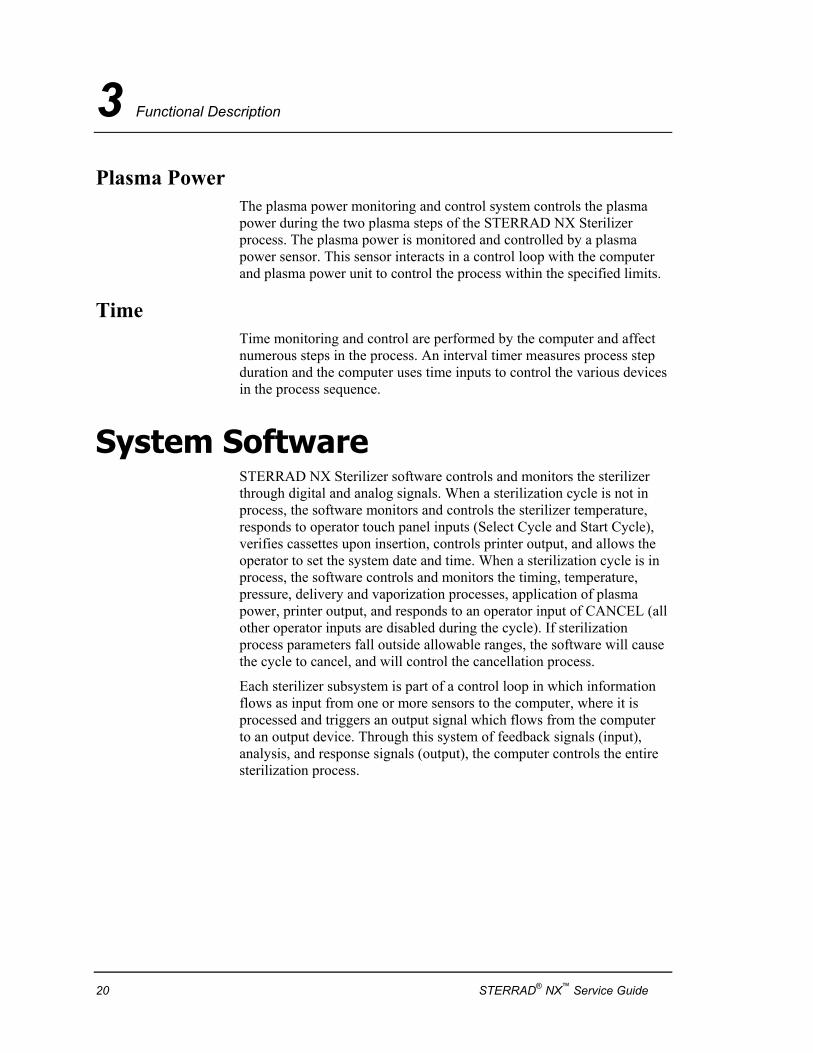
Plasma Power The plasma power monitoring and control system controls the plasma power during the two plasma steps of the STERRAD NX Sterilizer process. The plasma power is monitored and controlled by a plasma power sensor. This sensor interacts in a control loop with the computer and plasma power unit to control the process within the specified limits.
Time Time monitoring and control are performed by the computer and affect numerous steps in the process. An interval timer measures process step duration and the computer uses time inputs to control the various devices in the process sequence.
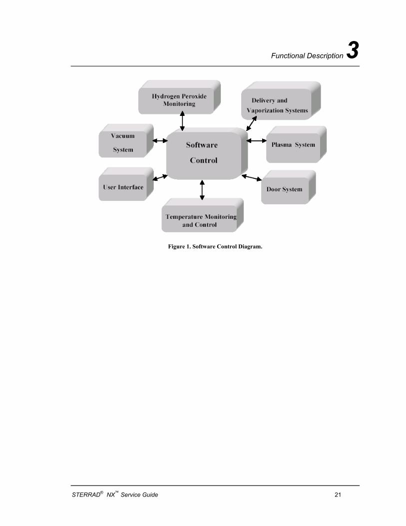
System Software STERRAD NX Sterilizer software controls and monitors the sterilizer through digital and analog signals. When a sterilization cycle is not in process, the software monitors and controls the sterilizer temperature, responds to operator touch panel inputs (Select Cycle and Start Cycle), verifies cassettes upon insertion, controls printer output, and allows the operator to set the system date and time. When a sterilization cycle is in process, the software controls and monitors the timing, temperature, pressure, delivery and vaporization processes, application of plasma power, printer output, and responds to an operator input of CANCEL (all other operator inputs are disabled during the cycle). If sterilization process parameters fall outside allowable ranges, the software will cause the cycle to cancel, and will control the cancellation process.
Each sterilizer subsystem is part of a control loop in which information flows as input from one or more sensors to the computer, where it is processed and triggers an output signal which flows from the computer to an output device. Through this system of feedback signals (input), analysis, and response signals (output), the computer controls the entire sterilization process.
20 STERRAD® NX™ Service Guide
Functional Description 3
Figure 1. Software Control Diagram.
STERRAD® NX™ Service Guide 21
3 Functional Description
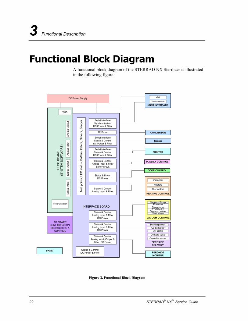
Functional Block Diagram A functional block diagram of the STERRAD NX Sterilizer is illustrated in the following figure.
AC POWERCONFIGURATION,DISTRIBUTION &
CONTROL
PEROXIDEDELIVERY
Piercing motor
PLASMA CONTROL
INTERFACE BOARD
DC Power Supply
DOOR CONTROL
Guide Motor
ULC
C B
OA
RD
(SYS
TEM
SO
FTW
ARE
)
VGA
Ana
log
Out
put
Dig
ital I
nput
Dig
ital O
utpu
tA
nalo
g In
put
Power Condition
USER INTERFACE
VGA
Touch Interface
PRINTER
Serial InterfaceSynchronization
DC Power & Filter
Serial InterfaceStatus & Control
DC Power & Filter
Status & ControlAnalog Input & Filter
Safety circuit
Status & ControlAnalog Input & Filter
Status & DriverDC Power
Status & ControlAnalog Input & Filter
DC Power
Status & ControlAnalog Input & Filter
DC Power
Status & ControlAnalog Input, Output &
Filter, DC Power
Test
poi
nts,
LE
D s
tatu
s, B
uffe
rs, F
ilter
s, D
river
s, B
eepe
r
HEATING CONTROL
Heaters
Thermistors
VACUUM CONTROL
Vacuum PumpPressure
TransducerATM Switch
Vacuum ValveVent Valve
PEROXIDEMONITOR
Air pumpDelivery valve
CONDENSOR
FANS
TE Driver
Status & ControlDC Power & Filter
Vaporizer
Cassette sensor
ScanerSerial InterfaceStatus & Control
DC Power & Filter
Figure 2. Functional Block Diagram
22 STERRAD® NX™ Service Guide
Functional Description 3
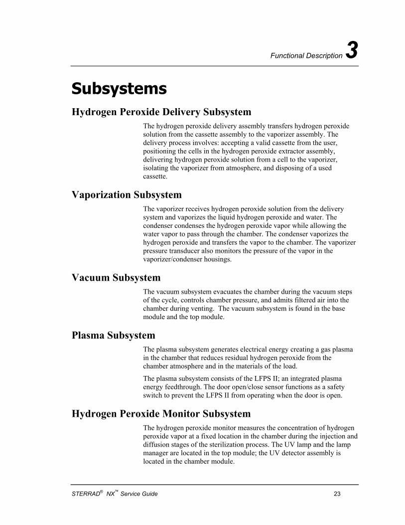
Subsystems Hydrogen Peroxide Delivery Subsystem
The hydrogen peroxide delivery assembly transfers hydrogen peroxide solution from the cassette assembly to the vaporizer assembly. The delivery process involves: accepting a valid cassette from the user, positioning the cells in the hydrogen peroxide extractor assembly, delivering hydrogen peroxide solution from a cell to the vaporizer, isolating the vaporizer from atmosphere, and disposing of a used cassette.
Vaporization Subsystem The vaporizer receives hydrogen peroxide solution from the delivery system and vaporizes the liquid hydrogen peroxide and water. The condenser condenses the hydrogen peroxide vapor while allowing the water vapor to pass through the chamber. The condenser vaporizes the hydrogen peroxide and transfers the vapor to the chamber. The vaporizer pressure transducer also monitors the pressure of the vapor in the vaporizer/condenser housings.
Vacuum Subsystem The vacuum subsystem evacuates the chamber during the vacuum steps of the cycle, controls chamber pressure, and admits filtered air into the chamber during venting. The vacuum subsystem is found in the base module and the top module.
Plasma Subsystem The plasma subsystem generates electrical energy creating a gas plasma in the chamber that reduces residual hydrogen peroxide from the chamber atmosphere and in the materials of the load.
The plasma subsystem consists of the LFPS II; an integrated plasma energy feedthrough. The door open/close sensor functions as a safety switch to prevent the LFPS II from operating when the door is open.
Hydrogen Peroxide Monitor Subsystem The hydrogen peroxide monitor measures the concentration of hydrogen peroxide vapor at a fixed location in the chamber during the injection and diffusion stages of the sterilization process. The UV lamp and the lamp manager are located in the top module; the UV detector assembly is located in the chamber module.
STERRAD® NX™ Service Guide 23
3 Functional Description
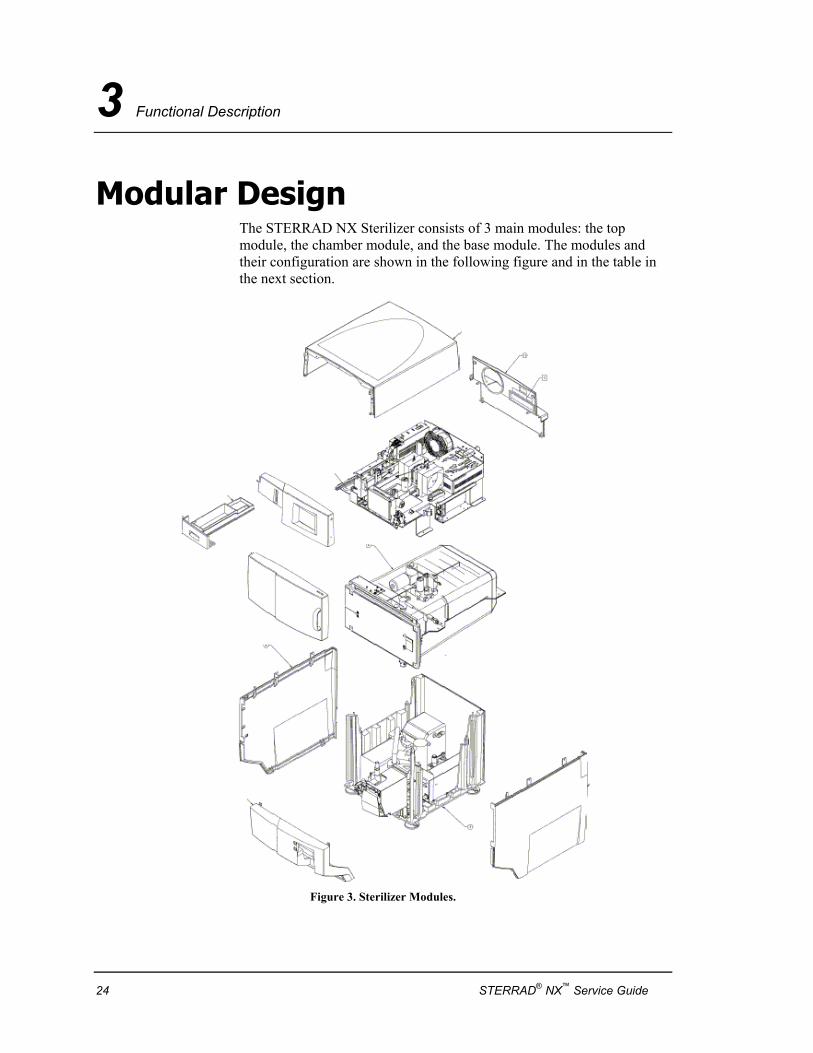
Modular Design The STERRAD NX Sterilizer consists of 3 main modules: the top module, the chamber module, and the base module. The modules and their configuration are shown in the following figure and in the table in the next section.
Figure 3. Sterilizer Modules.
24 STERRAD® NX™ Service Guide
Functional Description 3
Modules and Subsystem Details The following table details the 3 main modules and the subsystems contained in each of the modules. The following sections of this chapter describe each subsystem, its function and major components.
Module Name Components and Subsystems in the Module
Top Module
Chassis
Power inlet
Hydrogen peroxide delivery subsystem
Universal control board
System interface board (including network connector)
Alternating current (AC) distribution subsystem
Direct current (DC) power supply
Display and backlight assembly
Door lock assembly
Vaporizer/condenser assembly
Fan
Chamber Module Hydrogen peroxide monitor lamp
Chamber (including heaters, temperature sensors, and insulation)
Electrode and shelves
Vacuum fittings
Feedthrough
Door assembly (including heaters, temperature sensors, and insulation)
Door latch and open/closed sensor
Pressure sensors
Hydrogen peroxide monitor detector
Base Module
STERRAD® NX™ Service Guide 25
3 Functional Description
Vacuum subsystem
Low frequency plasma system (LFPS II) power supply
Printer subsystem
Circuit breaker
26 STERRAD® NX™ Service Guide
Functional Description 3
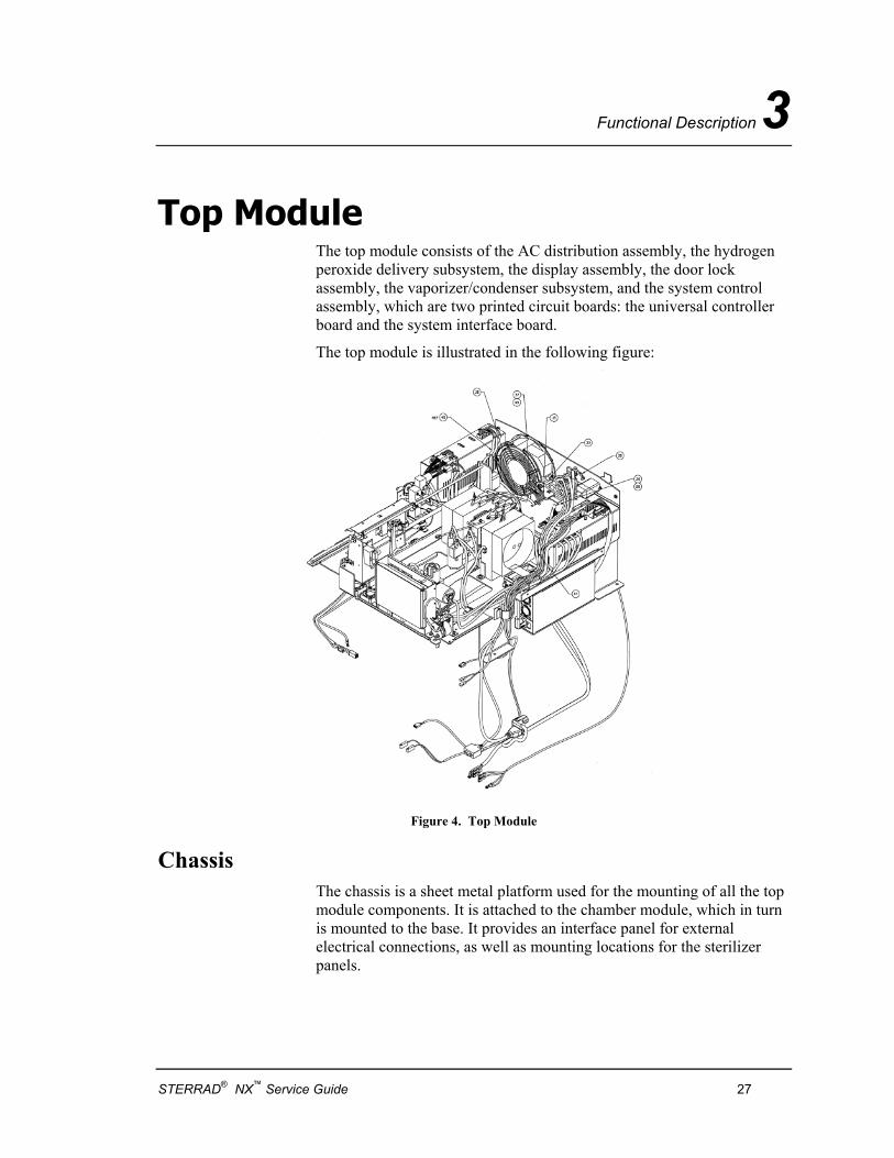
Top Module The top module consists of the AC distribution assembly, the hydrogen peroxide delivery subsystem, the display assembly, the door lock assembly, the vaporizer/condenser subsystem, and the system control assembly, which are two printed circuit boards: the universal controller board and the system interface board.
The top module is illustrated in the following figure:
Figure 4. Top Module
Chassis The chassis is a sheet metal platform used for the mounting of all the top module components. It is attached to the chamber module, which in turn is mounted to the base. It provides an interface panel for external electrical connections, as well as mounting locations for the sterilizer panels.
STERRAD® NX™ Service Guide 27
3 Functional Description
Access Panels The top module is covered by three access panels: the front top panel, the top panel, and the rear top panel. All are attached to the chassis by screws. They must be removed and reattached in a specified order, as some panels cover access to screws securing other panels.
Display Assembly The display assembly provides the graphical user interface. The user can interact with the sterilizer by reading system information and cycle status information and entering information and configuring the system through the touch-screen.
Cassette Drawer The cassette drawer holds a disposal box and up to three depleted sterilant cassettes. The cassette drawer can be pulled out and removed from the top module by releasing the retaining catch at the top rear end of the drawer.
Delivery System The delivery system accepts a cassette from the user, positions each of the cassette’s 10 cells in the hydrogen peroxide extractor assembly, delivers hydrogen peroxide solution from the cell to the vaporizer, isolates the vaporizer from the atmosphere, and disposes of used cassettes.
Vaporizer/Condenser The vaporizer/condenser subsystem is connected between the delivery system and the chamber. The vaporizer receives hydrogen peroxide solution from the delivery system and vaporizes the liquid hydrogen peroxide and water. The condenser condenses the hydrogen peroxide vapor while allowing the water vapor to pass through the chamber. The condenser vaporizes the hydrogen peroxide and delivers the vapor to the chamber. The vaporizer pressure transducer monitors the pressure of the vapor in the vaporizer/condenser assembly.
Power Inlet Connector The power inlet connector provides an attachment point for the cord set and holds the cord set in contact with the connector with a removable wire retainer. The inlet connector is located on the rear of the top module.
28 STERRAD® NX™ Service Guide
Functional Description 3
AC Distribution The AC distribution assembly provides On/Off power control and power distribution to the sterilizer. It interfaces with system software to provide AC power distribution to all subsystems including: Heaters for the chamber, door and vaporizer; DC power supply; vacuum pump; and plasma power supply.
The AC distribution assembly contains, inside the enclosure, a configuration jumper board which must be set to match the input voltage to be used by the sterilizer (120V/240V). The voltage setting of the jumper board is determined by how the jumper board is plugged into its socket.
DC Power Supply The DC power supply converts AC power to six different DC voltages. The voltages are +3.3V, +5V, +12V, +24V and +/-15V. All output voltages are regulated and the DC power supply has built-in over-current protection. The input to the DC power supply is supplied by AC power from the AC distribution assembly.
System Controller The system controller consists of the universal controller board and the system interface board. The system software resides in the Compact-Flash card on the universal controller board. The system controller provides all necessary electrical interconnections to components, provides software control to operate and monitor the sterilizer, provides external connections and access, and provides a control interface for the operator to input cycle information and access the sterilizer’s functions.
The system controller is configured as two circuit boards mounted together, inside a metal shielded enclosure. This assembly is mounted at the rear of the top module in such a way as to provide access to connectors on the interface board through slots and cutouts in the top rear panel.
Fan The fan is mounted on the rear wall of the top module. The fan exhausts heat from the top module.
STERRAD® NX™ Service Guide 29
3 Functional Description
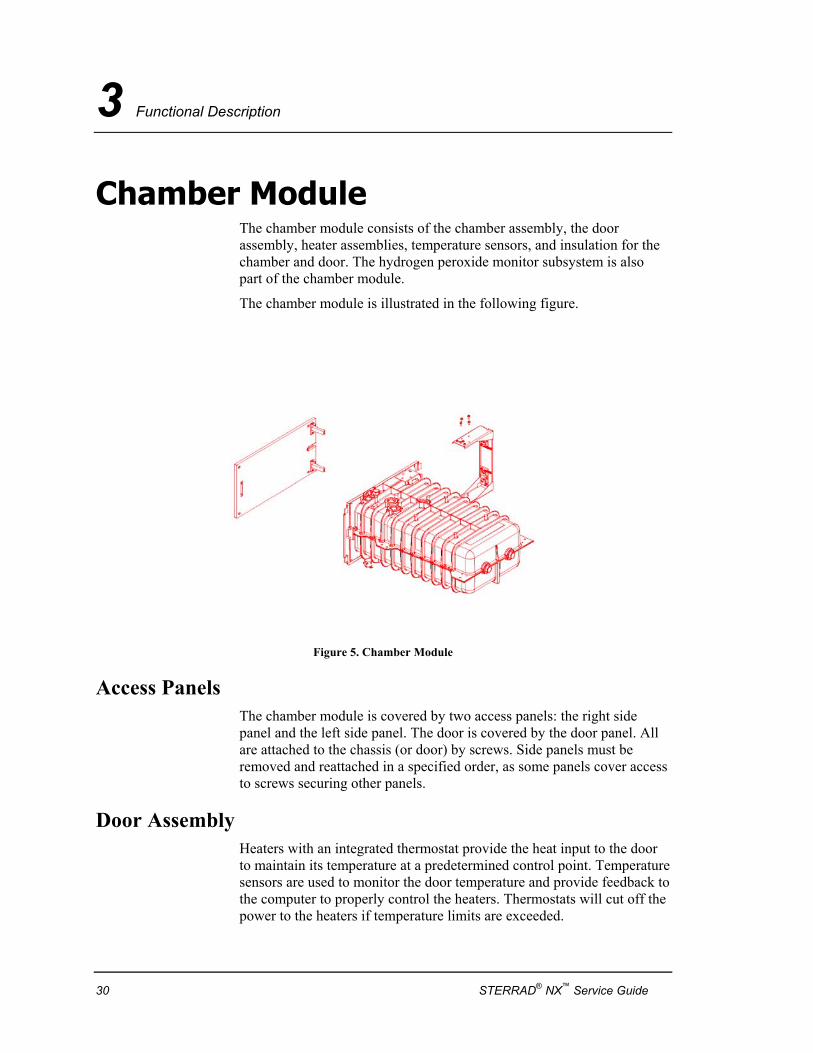
Chamber Module The chamber module consists of the chamber assembly, the door assembly, heater assemblies, temperature sensors, and insulation for the chamber and door. The hydrogen peroxide monitor subsystem is also part of the chamber module.
The chamber module is illustrated in the following figure.
Figure 5. Chamber Module
Access Panels The chamber module is covered by two access panels: the right side panel and the left side panel. The door is covered by the door panel. All are attached to the chassis (or door) by screws. Side panels must be removed and reattached in a specified order, as some panels cover access to screws securing other panels.
Door Assembly Heaters with an integrated thermostat provide the heat input to the door to maintain its temperature at a predetermined control point. Temperature sensors are used to monitor the door temperature and provide feedback to the computer to properly control the heaters. Thermostats will cut off the power to the heaters if temperature limits are exceeded.
30 STERRAD® NX™ Service Guide
Functional Description 3
Chamber and Shelves The chamber functions as the container where sterilization of a load takes place. The chamber assembly includes the chamber, electrode, shelves, heaters with thermistors, two temperature sensors, thermostat, and insulation.
Heaters with an integrated thermostat provide the heat input to the chamber to maintain its temperature at a predetermined control point. Temperature sensors are used to monitor the chamber temperature and provide feedback to the computer to properly control the heaters. Thermostats will cut off the power to the heaters if temperature limits are exceeded.
The two shelves are mounted on rails and can be pulled out of the chamber partially or completely.
Electrode The electrode is isolated from the chamber walls, door, and shelves and is used in the generation of plasma. The electrode distributes electrical energy uniformly throughout the chamber causing hydrogen peroxide molecules in the chamber to break apart and form plasma.
Feedthrough A feedthrough conductor, which is electrically isolated from the chamber wall, connects the electrode to the plasma power supply, which delivers power to the electrode.
STERRAD® NX™ Service Guide 31
3 Functional Description
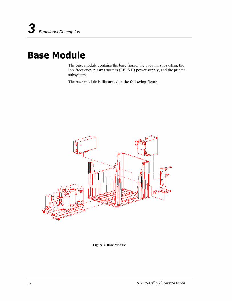
Base Module The base module contains the base frame, the vacuum subsystem, the low frequency plasma system (LFPS II) power supply, and the printer subsystem.
The base module is illustrated in the following figure.
Figure 6. Base Module
32 STERRAD® NX™ Service Guide
Functional Description 3
Frame and Chassis The base and chassis are the main support structure of the sterilizer and provide the means to move and support the sterilizer. The base frame provides mounting locations for exterior panels.
Access Panel The base module is covered by one access panel: the front bottom panel. It is attached to the chassis by two screws.
Circuit Breaker A magnetic-hydraulic automatic circuit breaker/switch is mounted on the right side of the front bottom panel. The circuit breaker/switch is used to turn power on and off and will trip open to protect the sterilizer if a current overload occurs.
LFPS II Power Supply The low frequency plasma system (LFPS II) power supply provides electrical energy to generate plasma in the chamber. The LFPS II output is connected to the feedthrough and electrode by a twin axial cable. A control cable connects the LFPS II to the system controller.
Printer The thermal printer produces a paper record of cycle information including process parameters, warning and error messages, troubleshooting information, machine and cycle identification information, and validation signature locations for the operator’s confirmations.
The printer assembly is mounted on the front right side of the base module. Access to the printer paper roll is provided by a flip-open door.
Vacuum Pump Assembly The vacuum pump assembly consists of a vacuum pump, exhaust oil mist filter, exhaust catalytic converter, oil return valve, vacuum control valve and related components. The vacuum pump assembly is mounted on a slide-out platform on the left side of the base module.
STERRAD® NX™ Service Guide 33
3 Functional Description
Diagnostic Functions and Tests The diagnostic function of the system software provides an automatic link between a failed cycle (cancelled cycle) and a specific subsystem function and performance test. The user or the service personnel can access the diagnostic functions independent of the cycle.
The STERRAD NX system software also provides predefined test sequences to determine the functionality and behavior of each subsystem. The diagnostic features of the system software provide service personnel detailed information about system performance.
The system diagnostic tool is designed to provide the following information:
♦ The result of the diagnostic test provides specific corrective action for the user or service person.
♦ The diagnostic test identifies a failed individual component or a group of components.
♦ Tests can better isolate failures to the subsystem level.
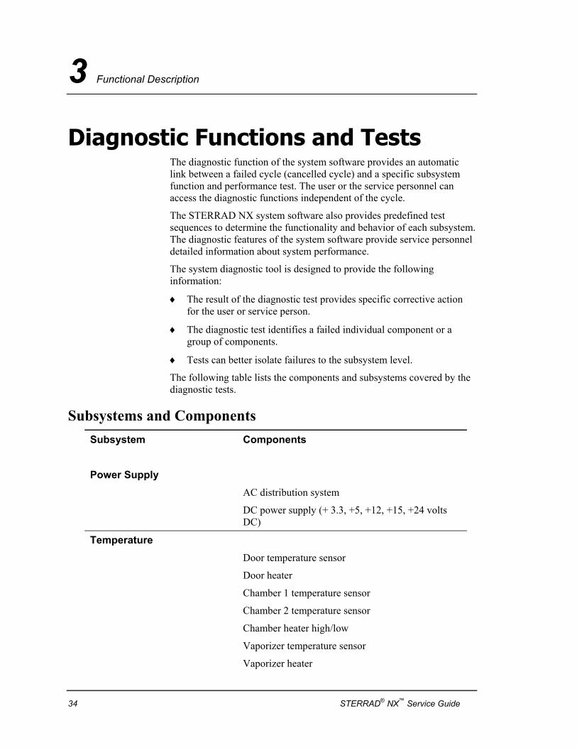
The following table lists the components and subsystems covered by the diagnostic tests.
Subsystems and Components Subsystem Components
Power Supply AC distribution system
DC power supply (+ 3.3, +5, +12, +15, +24 volts DC)
Temperature Door temperature sensor
Door heater
Chamber 1 temperature sensor
Chamber 2 temperature sensor
Chamber heater high/low
Vaporizer temperature sensor
Vaporizer heater
34 STERRAD® NX™ Service Guide
Functional Description 3
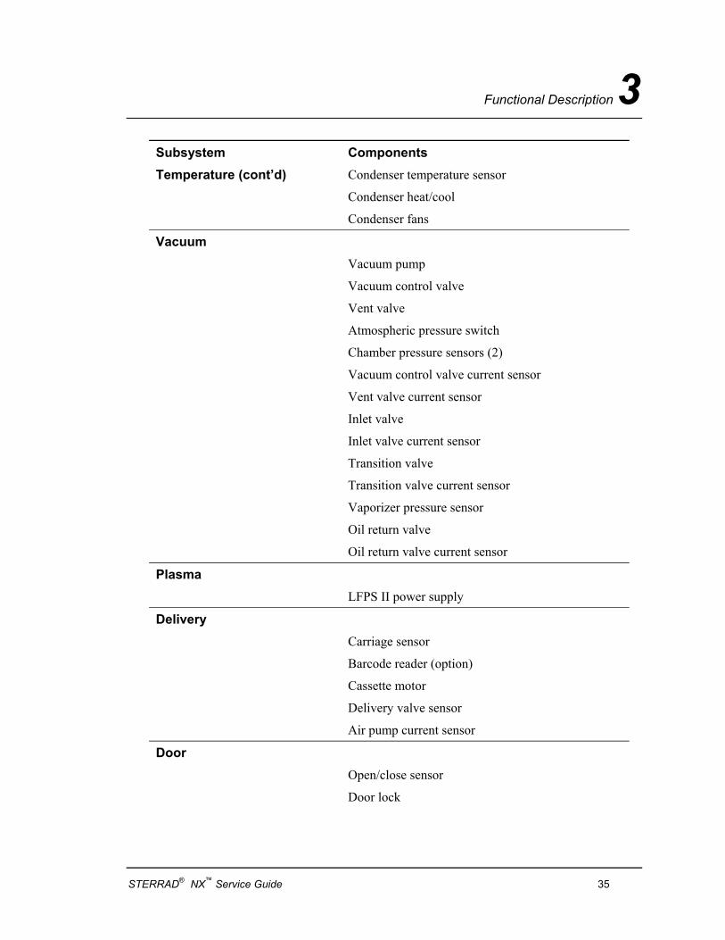
Subsystem Components Temperature (cont’d) Condenser temperature sensor
Condenser heat/cool
Condenser fans
Vacuum Vacuum pump Vacuum control valve Vent valve Atmospheric pressure switch Chamber pressure sensors (2) Vacuum control valve current sensor Vent valve current sensor Inlet valve Inlet valve current sensor Transition valve Transition valve current sensor Vaporizer pressure sensor Oil return valve Oil return valve current sensor
Plasma LFPS II power supply
Delivery Carriage sensor
Barcode reader (option)
Cassette motor
Delivery valve sensor
Air pump current sensor
Door Open/close sensor
Door lock
STERRAD® NX™ Service Guide 35
3 Functional Description
Subsystem Components Hydrogen Peroxide Monitor Hydrogen peroxide detector
Ultraviolet lamp
Display VGA display
Touch panel
Backlight
Printer Printer
Fan Fan
Fan current sensor
Sound Alarm enunciator
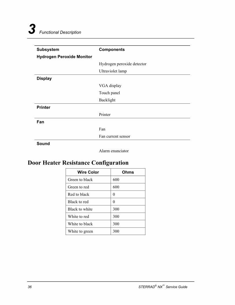
Door Heater Resistance Configuration Wire Color Ohms
Green to black 600
Green to red 600
Red to black 0
Black to red 0
Black to white 300
White to red 300
White to black 300
White to green 300
36 STERRAD® NX™ Service Guide
Functional Description 3
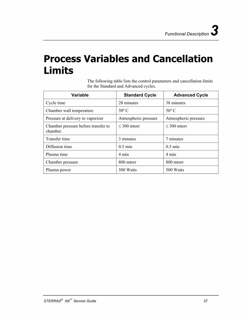
Process Variables and Cancellation Limits
The following table lists the control parameters and cancellation limits for the Standard and Advanced cycles.
Variable Standard Cycle Advanced Cycle
Cycle time 28 minutes 38 minutes
Chamber wall temperature 50º C 50º C
Pressure at delivery to vaporizer Atmospheric pressure Atmospheric pressure
Chamber pressure before transfer to chamber.
≤ 300 mtorr ≤ 300 mtorr
Transfer time 3 minutes 7 minutes
Diffusion time 0.5 min 0.5 min
Plasma time 4 min 4 min
Chamber pressure 800 mtorr 800 mtorr
Plasma power 500 Watts 500 Watts
STERRAD® NX™ Service Guide 37

Diagnostic Tests and Error Messages 4
Chapter 4.
Diagnostic Tests and Error Messages
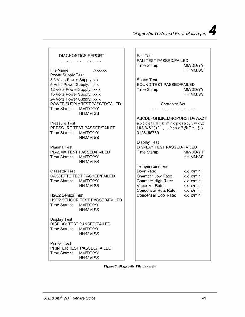
Diagnostic Files Diagnostic files are created by the diagnostics tests. The files contain details about the tests and the outcomes (Passed or Failed) of each. An example of a Diagnostic file is shown in the figure following the table.
Touch Diagnostic Files to display a list of reports created by the Diagnostics function. Scroll through the list and touch the report you wish to view. Touch View to display the selected report. Touch Back to return to the Additional Utilities menu.
Diagnostics 4 Note: The temperature tests run automatically for about
1 hour. These tests should only be used if there is a suspected temperature problem.
Touch Diagnostics to start automatic diagnostic testing of the sterilizer. When started, the diagnostics function prompts you to select one of two types of tests (either “Temperature” or “Other Tests”). If “Other Tests” is selected, the sterilizer runs 10 operator-assisted tests of the sterilizer subsystems. You may skip one or more tests in the automatic sequence by touching Cancel when a test begins. The program advances to the next test in the sequence.
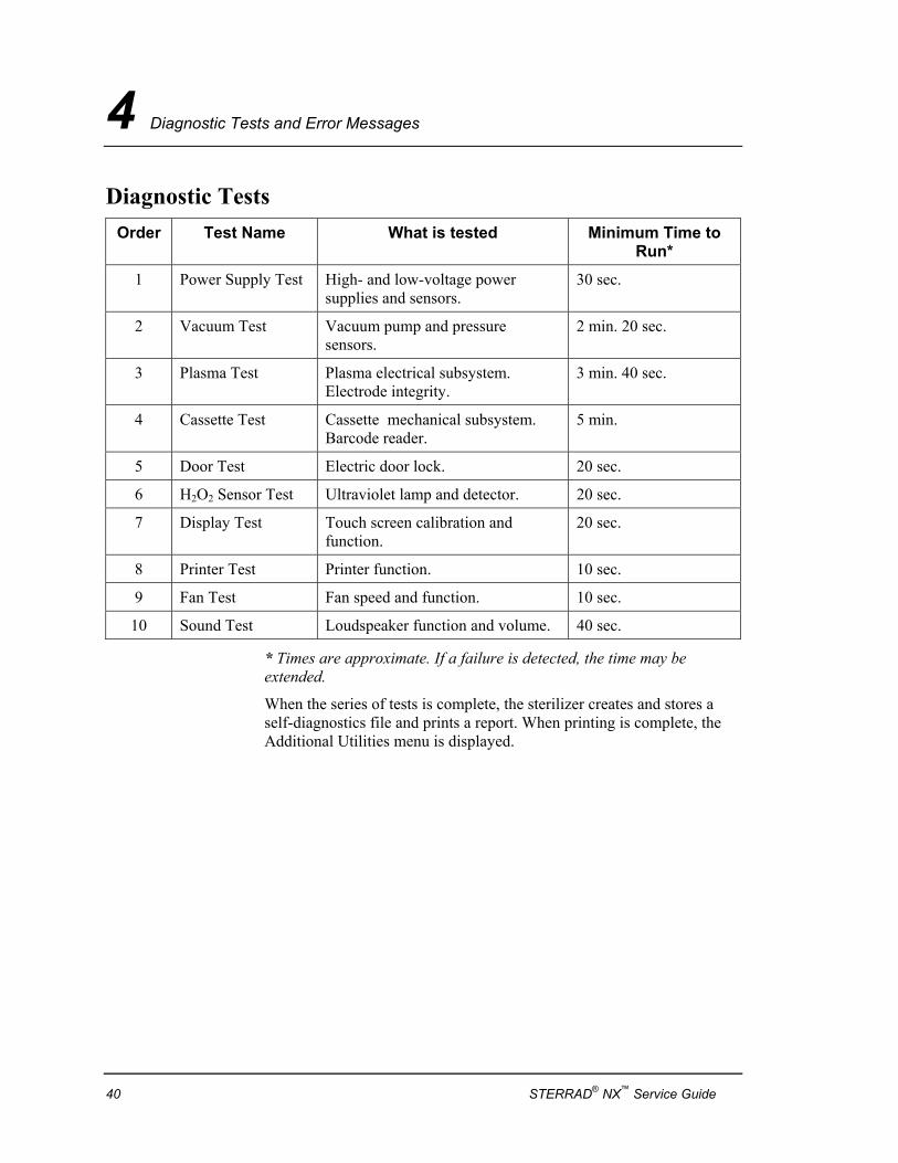
The 10 tests and the sterilizer elements that are tested are listed in the order in which they occur in the following table.
STERRAD® NX™ Service Guide 39
4 Diagnostic Tests and Error Messages
Diagnostic Tests Order Test Name What is tested Minimum Time to
Run* 1 Power Supply Test High- and low-voltage power
supplies and sensors. 30 sec.
2 Vacuum Test Vacuum pump and pressure sensors.
2 min. 20 sec.
3 Plasma Test Plasma electrical subsystem. Electrode integrity.
3 min. 40 sec.
4 Cassette Test Cassette mechanical subsystem. Barcode reader.
5 min.
5 Door Test Electric door lock. 20 sec.
6 H2O2 Sensor Test Ultraviolet lamp and detector. 20 sec.
7 Display Test Touch screen calibration and function.
20 sec.
8 Printer Test Printer function. 10 sec.
9 Fan Test Fan speed and function. 10 sec.
10 Sound Test Loudspeaker function and volume. 40 sec.
* Times are approximate. If a failure is detected, the time may be extended.
When the series of tests is complete, the sterilizer creates and stores a self-diagnostics file and prints a report. When printing is complete, the Additional Utilities menu is displayed.
40 STERRAD® NX™ Service Guide
Diagnostic Tests and Error Messages 4
DIAGNOSTICS REPORT . . . . . . . . . . . . . .
File Name: /xxxxxxPower Supply Test3.3 Volts Power Supply: x.x5 Volts Power Supply: x.x12 Volts Power Supply: xx.x15 Volts Power Supply: xx.x24 Volts Power Supply: xx.xPOWER SUPPLY TEST PASSED/FAILEDTime Stamp: MM/DD/YY
HH:MM:SS
Pressure TestPRESSURE TEST PASSED/FAILEDTime Stamp: MM/DD/YY
HH:MM:SS
Plasma TestPLASMA TEST PASSED/FAILEDTime Stamp: MM/DD/YY
HH:MM:SS
Cassette TestCASSETTE TEST PASSED/FAILEDTime Stamp: MM/DD/YY
HH:MM:SS
H2O2 Sensor TestH2O2 SENSOR TEST PASSED/FAILEDTime Stamp: MM/DD/YY
HH:MM:SS
Display TestDISPLAY TEST PASSED/FAILEDTime Stamp: MM/DD/YY
HH:MM:SS
Printer TestPRINTER TEST PASSED/FAILEDTime Stamp: MM/DD/YY
HH:MM:SS
Fan TestFAN TEST PASSED/FAILEDTime Stamp: MM/DD/YY
HH:MM:SS
Sound TestSOUND TEST PASSED/FAILEDTime Stamp: MM/DD/YY
HH:MM:SS
Character Set . . . . . . . . . . . . . .
ABCDEFGHIJKLMNOPQRSTUVWXZYa b c d e f g h i j k l m n o p q r s t u v w x yz! # $ % & ' ( ) * + , _ . / : ; < > ? @ [ ] ̂ _ { | }0123456789
Display TestDISPLAY TEST PASSED/FAILEDTime Stamp: MM/DD/YY
HH:MM:SS
Temperature TestDoor Rate: x.x c/minChamber Low Rate: x.x c/minChamber High Rate: x.x c/minVaporizer Rate: x.x c/minCondenser Heat Rate: x.x c/minCondenser Cool Rate: x.x c/min
Figure 7. Diagnostic File Example
STERRAD® NX™ Service Guide 41

4 Diagnostic Tests and Error Messages
Troubleshooting Most sterilizer operating problems are accompanied by an error message. These messages are useful in determining the source of the problem. In many cases you can take remedial actions to correct the source of the problem and thereby return the sterilizer to normal operation. In other cases, the problem is caused by a component failure that requires adjustment or replacement.
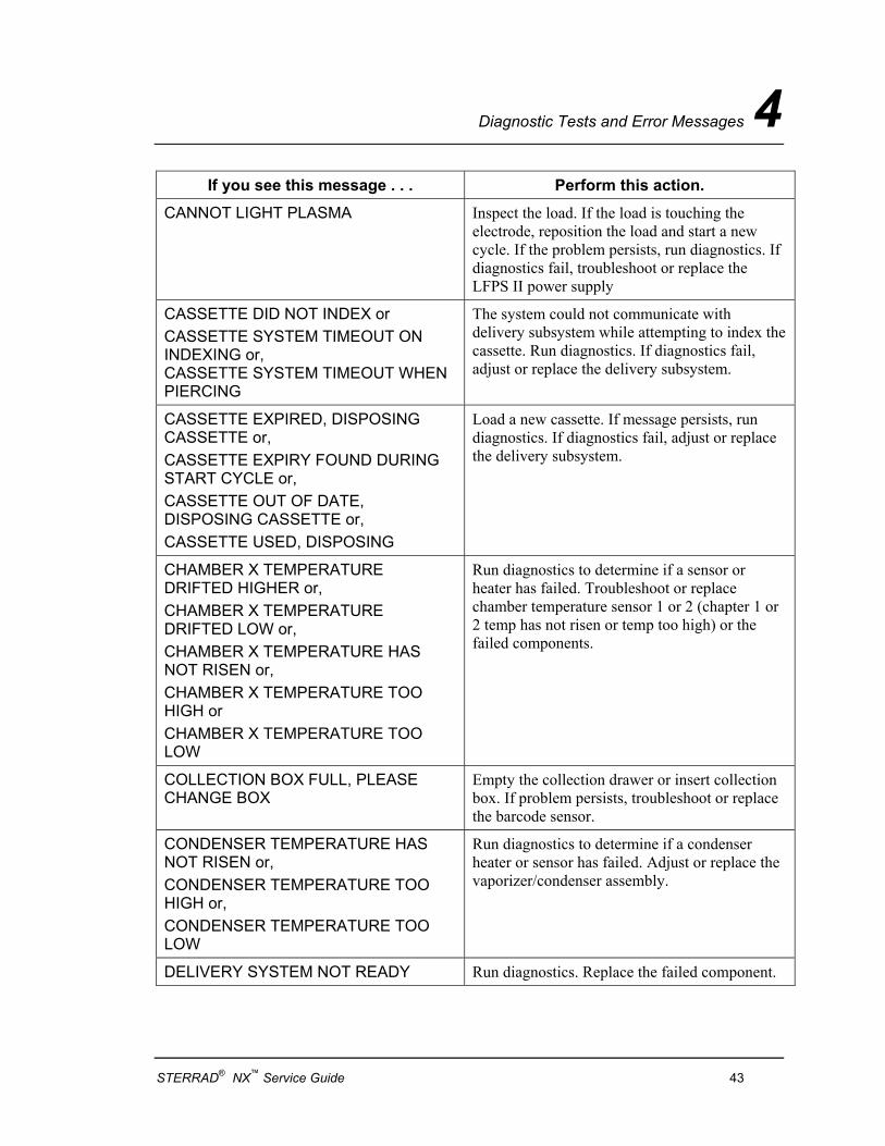
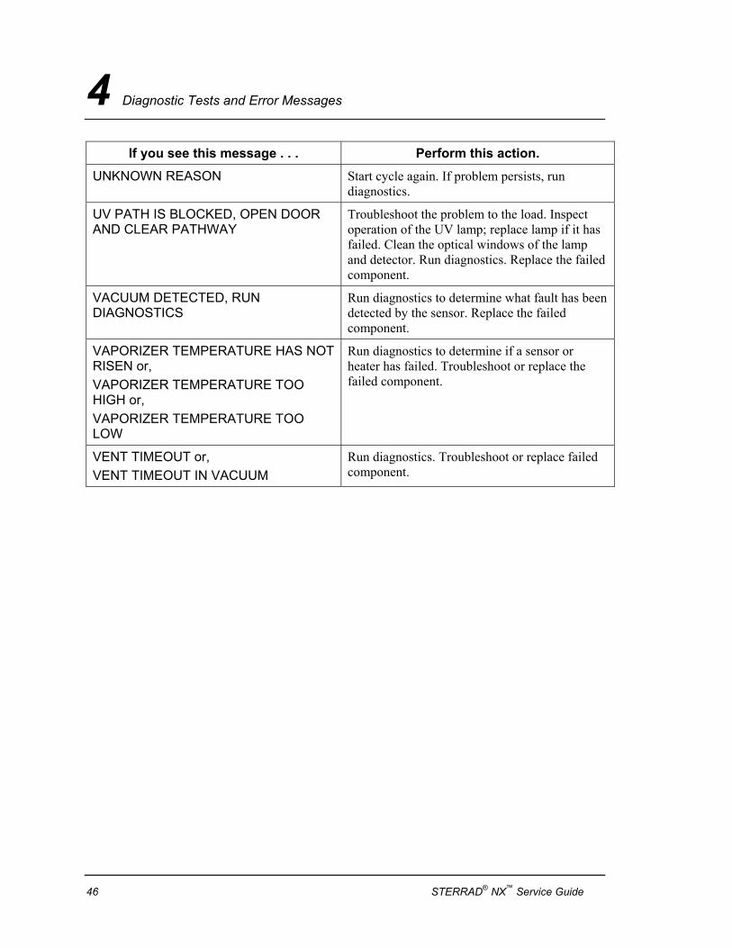
Error Messages If an error occurs during operation, the sterilizer may allow you to run a diagnostic test immediately. When prompted to do so, touch Confirm to perform the diagnostic test. A diagnostic test displays and prints a diagnostic message when the test is completed. Some diagnostic messages indicate conditions that you may be able to remedy.
If you see this message . . . Perform this action.
12 VOLT SUPPLY OUT OF RANGE or, 15 VOLT SUPPLY OUT OF RANGE or, 24 VOLT SUPPLY OUT OF RANGE or, 3.3 VOLT SUPPLY OUT OF RANGE or, 5 VOLT SUPPLY OUT OF RANGE
Run the diagnostics to determine if the power supply is out of tolerance. If the diagnostics fail, replace the power supply.
AUTO ADJUSTMENT FAILED A fault was detected during the hydrogen peroxide auto-adjustment.
BARCODE DATA ERROR, EJECTING CASSETTE or BARCODE NOT DETECTED, EJECTING
Inspect the cassette to determine if the barcode is valid. Make sure the barcode is clean and legible. Insert the cassette again or try a new cassette. If the problem persists, run the diagnostics. Adjust or replace the barcode sensor.
CANNOT DISPOSE CASSETTE, RUN DIAGNOSTICS
Never put your hand inside the machine to move a cassette. Select “Dispose Cassette” to move the cassette into the disposal drawer. If the problem persists, run diagnostics. If diagnostics fail, adjust or replace the delivery subsystem.
CANNOT EJECT CASSETTE, RUN DIAGNOSTICS
Run diagnostics. If diagnostics fail, adjust or replace the delivery subsystem.
42 STERRAD® NX™ Service Guide
Diagnostic Tests and Error Messages 4
If you see this message . . . Perform this action.
CANNOT LIGHT PLASMA Inspect the load. If the load is touching the electrode, reposition the load and start a new cycle. If the problem persists, run diagnostics. If diagnostics fail, troubleshoot or replace the LFPS II power supply
CASSETTE DID NOT INDEX or CASSETTE SYSTEM TIMEOUT ON INDEXING or, CASSETTE SYSTEM TIMEOUT WHEN PIERCING
The system could not communicate with delivery subsystem while attempting to index the cassette. Run diagnostics. If diagnostics fail, adjust or replace the delivery subsystem.
CASSETTE EXPIRED, DISPOSING CASSETTE or, CASSETTE EXPIRY FOUND DURING START CYCLE or, CASSETTE OUT OF DATE, DISPOSING CASSETTE or, CASSETTE USED, DISPOSING
Load a new cassette. If message persists, run diagnostics. If diagnostics fail, adjust or replace the delivery subsystem.
CHAMBER X TEMPERATURE DRIFTED HIGHER or, CHAMBER X TEMPERATURE DRIFTED LOW or, CHAMBER X TEMPERATURE HAS NOT RISEN or, CHAMBER X TEMPERATURE TOO HIGH or CHAMBER X TEMPERATURE TOO LOW
Run diagnostics to determine if a sensor or heater has failed. Troubleshoot or replace chamber temperature sensor 1 or 2 (chapter 1 or 2 temp has not risen or temp too high) or the failed components.
COLLECTION BOX FULL, PLEASE CHANGE BOX
Empty the collection drawer or insert collection box. If problem persists, troubleshoot or replace the barcode sensor.
CONDENSER TEMPERATURE HAS NOT RISEN or, CONDENSER TEMPERATURE TOO HIGH or, CONDENSER TEMPERATURE TOO LOW
Run diagnostics to determine if a condenser heater or sensor has failed. Adjust or replace the vaporizer/condenser assembly.
DELIVERY SYSTEM NOT READY Run diagnostics. Replace the failed component.
STERRAD® NX™ Service Guide 43
4 Diagnostic Tests and Error Messages
If you see this message . . . Perform this action.
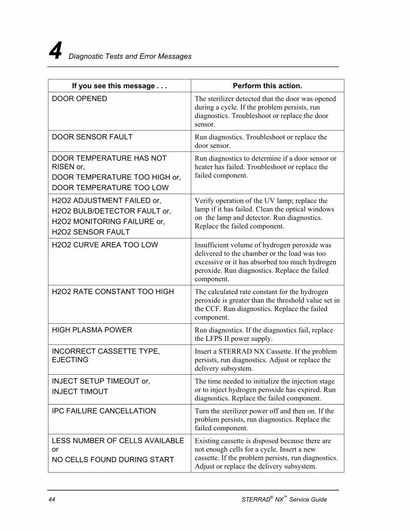
DOOR OPENED The sterilizer detected that the door was opened during a cycle. If the problem persists, run diagnostics. Troubleshoot or replace the door sensor.
DOOR SENSOR FAULT Run diagnostics. Troubleshoot or replace the door sensor.
DOOR TEMPERATURE HAS NOT RISEN or, DOOR TEMPERATURE TOO HIGH or, DOOR TEMPERATURE TOO LOW
Run diagnostics to determine if a door sensor or heater has failed. Troubleshoot or replace the failed component.
H2O2 ADJUSTMENT FAILED or, H2O2 BULB/DETECTOR FAULT or, H2O2 MONITORING FAILURE or, H2O2 SENSOR FAULT
Verify operation of the UV lamp; replace the lamp if it has failed. Clean the optical windows on the lamp and detector. Run diagnostics. Replace the failed component.
H2O2 CURVE AREA TOO LOW Insufficient volume of hydrogen peroxide was delivered to the chamber or the load was too excessive or it has absorbed too much hydrogen peroxide. Run diagnostics. Replace the failed component.
H2O2 RATE CONSTANT TOO HIGH The calculated rate constant for the hydrogen peroxide is greater than the threshold value set in the CCF. Run diagnostics. Replace the failed component.
HIGH PLASMA POWER Run diagnostics. If the diagnostics fail, replace the LFPS II power supply.
INCORRECT CASSETTE TYPE, EJECTING
Insert a STERRAD NX Cassette. If the problem persists, run diagnostics. Adjust or replace the delivery subsystem.
INJECT SETUP TIMEOUT or, INJECT TIMOUT
The time needed to initialize the injection stage or to inject hydrogen peroxide has expired. Run diagnostics. Replace the failed component.
IPC FAILURE CANCELLATION Turn the sterilizer power off and then on. If the problem persists, run diagnostics. Replace the failed component.
LESS NUMBER OF CELLS AVAILABLE or NO CELLS FOUND DURING START
Existing cassette is disposed because there are not enough cells for a cycle. Insert a new cassette. If the problem persists, run diagnostics. Adjust or replace the delivery subsystem.
44 STERRAD® NX™ Service Guide
Diagnostic Tests and Error Messages 4
If you see this message . . . Perform this action.
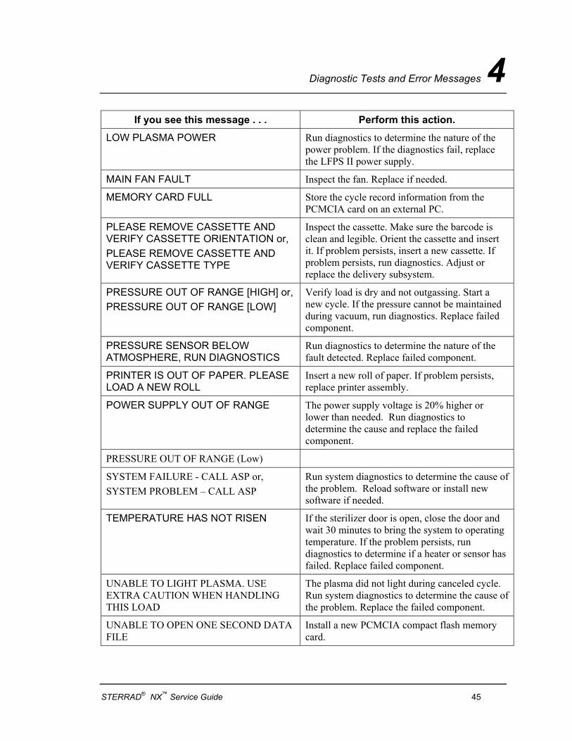
LOW PLASMA POWER Run diagnostics to determine the nature of the power problem. If the diagnostics fail, replace the LFPS II power supply.
MAIN FAN FAULT Inspect the fan. Replace if needed.
MEMORY CARD FULL Store the cycle record information from the PCMCIA card on an external PC.
PLEASE REMOVE CASSETTE AND VERIFY CASSETTE ORIENTATION or, PLEASE REMOVE CASSETTE AND VERIFY CASSETTE TYPE
Inspect the cassette. Make sure the barcode is clean and legible. Orient the cassette and insert it. If problem persists, insert a new cassette. If problem persists, run diagnostics. Adjust or replace the delivery subsystem.
PRESSURE OUT OF RANGE [HIGH] or, PRESSURE OUT OF RANGE [LOW]
Verify load is dry and not outgassing. Start a new cycle. If the pressure cannot be maintained during vacuum, run diagnostics. Replace failed component.
PRESSURE SENSOR BELOW ATMOSPHERE, RUN DIAGNOSTICS
Run diagnostics to determine the nature of the fault detected. Replace failed component.
PRINTER IS OUT OF PAPER. PLEASE LOAD A NEW ROLL
Insert a new roll of paper. If problem persists, replace printer assembly.
POWER SUPPLY OUT OF RANGE The power supply voltage is 20% higher or lower than needed. Run diagnostics to determine the cause and replace the failed component.
PRESSURE OUT OF RANGE (Low)
SYSTEM FAILURE - CALL ASP or, SYSTEM PROBLEM – CALL ASP
Run system diagnostics to determine the cause of the problem. Reload software or install new software if needed.
TEMPERATURE HAS NOT RISEN If the sterilizer door is open, close the door and wait 30 minutes to bring the system to operating temperature. If the problem persists, run diagnostics to determine if a heater or sensor has failed. Replace failed component.
UNABLE TO LIGHT PLASMA. USE EXTRA CAUTION WHEN HANDLING THIS LOAD
The plasma did not light during canceled cycle. Run system diagnostics to determine the cause of the problem. Replace the failed component.
UNABLE TO OPEN ONE SECOND DATA FILE
Install a new PCMCIA compact flash memory card.
STERRAD® NX™ Service Guide 45
4 Diagnostic Tests and Error Messages
If you see this message . . . Perform this action.
UNKNOWN REASON Start cycle again. If problem persists, run diagnostics.
UV PATH IS BLOCKED, OPEN DOOR AND CLEAR PATHWAY
Troubleshoot the problem to the load. Inspect operation of the UV lamp; replace lamp if it has failed. Clean the optical windows of the lamp and detector. Run diagnostics. Replace the failed component.
VACUUM DETECTED, RUN DIAGNOSTICS
Run diagnostics to determine what fault has been detected by the sensor. Replace the failed component.
VAPORIZER TEMPERATURE HAS NOT RISEN or, VAPORIZER TEMPERATURE TOO HIGH or, VAPORIZER TEMPERATURE TOO LOW
Run diagnostics to determine if a sensor or heater has failed. Troubleshoot or replace the failed component.
VENT TIMEOUT or, VENT TIMEOUT IN VACUUM
Run diagnostics. Troubleshoot or replace failed component.
46 STERRAD® NX™ Service Guide
Diagnostic Tests and Error Messages 4
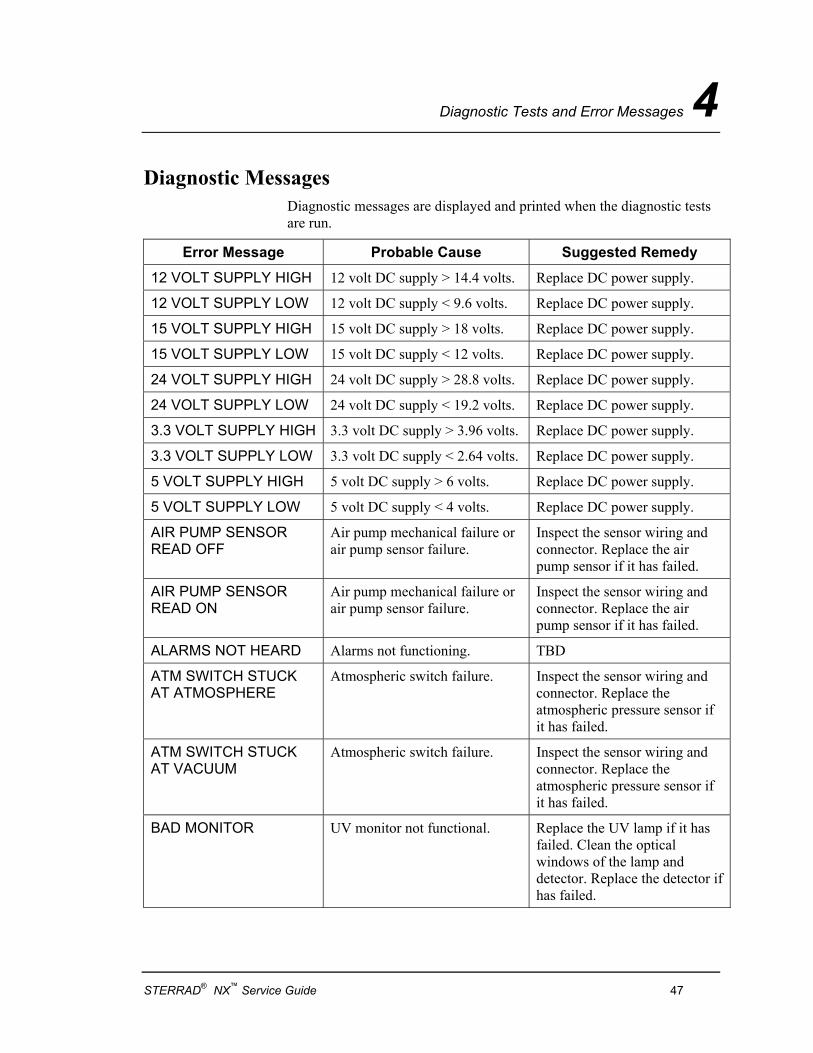
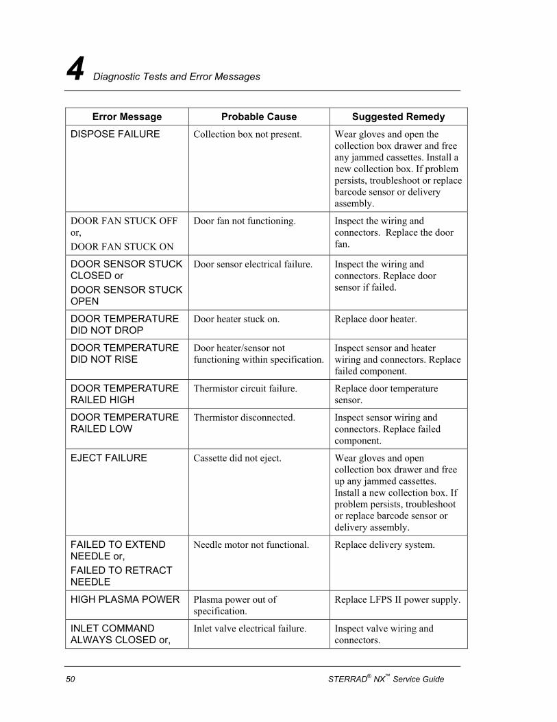
Diagnostic Messages Diagnostic messages are displayed and printed when the diagnostic tests are run.
Error Message Probable Cause Suggested Remedy
12 VOLT SUPPLY HIGH 12 volt DC supply > 14.4 volts. Replace DC power supply.
12 VOLT SUPPLY LOW 12 volt DC supply < 9.6 volts. Replace DC power supply.
15 VOLT SUPPLY HIGH 15 volt DC supply > 18 volts. Replace DC power supply.
15 VOLT SUPPLY LOW 15 volt DC supply < 12 volts. Replace DC power supply.
24 VOLT SUPPLY HIGH 24 volt DC supply > 28.8 volts. Replace DC power supply.
24 VOLT SUPPLY LOW 24 volt DC supply < 19.2 volts. Replace DC power supply.
3.3 VOLT SUPPLY HIGH 3.3 volt DC supply > 3.96 volts. Replace DC power supply.
3.3 VOLT SUPPLY LOW 3.3 volt DC supply < 2.64 volts. Replace DC power supply.
5 VOLT SUPPLY HIGH 5 volt DC supply > 6 volts. Replace DC power supply.
5 VOLT SUPPLY LOW 5 volt DC supply < 4 volts. Replace DC power supply.
AIR PUMP SENSOR READ OFF
Air pump mechanical failure or air pump sensor failure.
Inspect the sensor wiring and connector. Replace the air pump sensor if it has failed.
AIR PUMP SENSOR READ ON
Air pump mechanical failure or air pump sensor failure.
Inspect the sensor wiring and connector. Replace the air pump sensor if it has failed.
ALARMS NOT HEARD Alarms not functioning. TBD
ATM SWITCH STUCK AT ATMOSPHERE
Atmospheric switch failure. Inspect the sensor wiring and connector. Replace the atmospheric pressure sensor if it has failed.
ATM SWITCH STUCK AT VACUUM
Atmospheric switch failure. Inspect the sensor wiring and connector. Replace the atmospheric pressure sensor if it has failed.
BAD MONITOR UV monitor not functional. Replace the UV lamp if it has failed. Clean the optical windows of the lamp and detector. Replace the detector if has failed.
STERRAD® NX™ Service Guide 47
4 Diagnostic Tests and Error Messages
Error Message Probable Cause Suggested Remedy
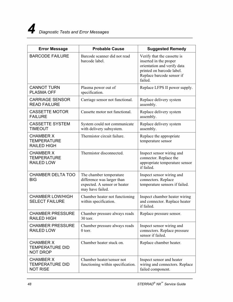
BARCODE FAILURE Barcode scanner did not read barcode label.
Verify that the cassette is inserted in the proper orientation and verify data printed on barcode label. Replace barcode sensor if failed.
CANNOT TURN PLASMA OFF
Plasma power out of specification.
Replace LFPS II power supply.
CARRIAGE SENSOR READ FAILURE
Carriage sensor not functional. Replace delivery system assembly.
CASSETTE MOTOR FAILURE
Cassette motor not functional. Replace delivery system assembly.
CASSETTE SYSTEM TIMEOUT
System could not communicate with delivery subsystem.
Replace delivery system assembly.
CHAMBER X TEMPERATURE RAILED HIGH
Thermistor circuit failure. Replace the appropriate temperature sensor
CHAMBER X TEMPERATURE RAILED LOW
Thermistor disconnected. Inspect sensor wiring and connector. Replace the appropriate temperature sensor if failed.
CHAMBER DELTA TOO BIG
The chamber temperature difference was larger than expected. A sensor or heater may have failed.
Inspect sensor wiring and connectors. Replace temperature sensors if failed.
CHAMBER LOW/HIGH SELECT FAILURE
Chamber heater not functioning within specification.
Inspect chamber heater wiring and connector. Replace heater if failed.
CHAMBER PRESSURE RAILED HIGH
Chamber pressure always reads 30 torr.
Replace pressure sensor.
CHAMBER PRESSURE RAILED LOW
Chamber pressure always reads 0 torr.
Inspect sensor wiring and connectors. Replace pressure sensor if failed.
CHAMBER X TEMPERATURE DID NOT DROP
Chamber heater stuck on. Replace chamber heater.
CHAMBER X TEMPERATURE DID NOT RISE
Chamber heater/sensor not functioning within specification.
Inspect sensor and heater wiring and connectors. Replace failed component.
48 STERRAD® NX™ Service Guide
Diagnostic Tests and Error Messages 4
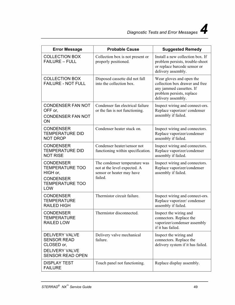
Error Message Probable Cause Suggested Remedy
COLLECTION BOX FAILURE – FULL
Collection box is not present or properly positioned.
Install a new collection box. If problem persists, trouble-shoot or replace barcode sensor or delivery assembly.
COLLECTION BOX FAILURE - NOT FULL
Disposed cassette did not fall into the collection box.
Wear gloves and open the collection box drawer and free any jammed cassettes. If problem persists, replace delivery assembly.
CONDENSER FAN NOT OFF or, CONDENSER FAN NOT ON
Condenser fan electrical failure or the fan is not functioning.
Inspect wiring and connect-ors. Replace vaporizer/ condenser assembly if failed.
CONDENSER TEMPERATURE DID NOT DROP
Condenser heater stuck on. Inspect wiring and connectors. Replace vaporizer/condenser assembly if failed.
CONDENSER TEMPERATURE DID NOT RISE
Condenser heater/sensor not functioning within specification.
Inspect wiring and connectors. Replace vaporizer/condenser assembly if failed.
CONDENSER TEMPERATURE TOO HIGH or, CONDENSER TEMPERATURE TOO LOW
The condenser temperature was not at the level expected. A sensor or heater may have failed.
Inspect wiring and connectors. Replace vaporizer/condenser assembly if failed.
CONDENSER TEMPERATURE RAILED HIGH
Thermistor circuit failure. Inspect wiring and connect-ors. Replace vaporizer/ condenser assembly if failed.
CONDENSER TEMPERATURE RAILED LOW
Thermistor disconnected. Inspect the wiring and connectors. Replace the vaporizer/condenser assembly if it has failed.
DELIVERY VALVE SENSOR READ CLOSED or, DELIVERY VALVE SENSOR READ OPEN
Delivery valve mechanical failure.
Inspect the wiring and connectors. Replace the delivery system if it has failed.
DISPLAY TEST FAILURE
Touch panel not functioning. Replace display assembly.
STERRAD® NX™ Service Guide 49
4 Diagnostic Tests and Error Messages
Error Message Probable Cause Suggested Remedy
DISPOSE FAILURE Collection box not present. Wear gloves and open the collection box drawer and free any jammed cassettes. Install a new collection box. If problem persists, troubleshoot or replace barcode sensor or delivery assembly.
DOOR FAN STUCK OFF or, DOOR FAN STUCK ON
Door fan not functioning. Inspect the wiring and connectors. Replace the door fan.
DOOR SENSOR STUCK CLOSED or DOOR SENSOR STUCK OPEN
Door sensor electrical failure. Inspect the wiring and connectors. Replace door sensor if failed.
DOOR TEMPERATURE DID NOT DROP
Door heater stuck on. Replace door heater.
DOOR TEMPERATURE DID NOT RISE
Door heater/sensor not functioning within specification.
Inspect sensor and heater wiring and connectors. Replace failed component.
DOOR TEMPERATURE RAILED HIGH
Thermistor circuit failure. Replace door temperature sensor.
DOOR TEMPERATURE RAILED LOW
Thermistor disconnected. Inspect sensor wiring and connectors. Replace failed component.
EJECT FAILURE Cassette did not eject. Wear gloves and open collection box drawer and free up any jammed cassettes. Install a new collection box. If problem persists, troubleshoot or replace barcode sensor or delivery assembly.
FAILED TO EXTEND NEEDLE or, FAILED TO RETRACT NEEDLE
Needle motor not functional. Replace delivery system.
HIGH PLASMA POWER Plasma power out of specification.
Replace LFPS II power supply.
INLET COMMAND ALWAYS CLOSED or,
Inlet valve electrical failure. Inspect valve wiring and connectors.
50 STERRAD® NX™ Service Guide
Diagnostic Tests and Error Messages 4
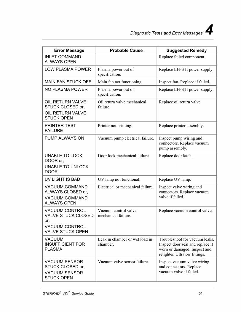
Error Message Probable Cause Suggested Remedy INLET COMMAND ALWAYS OPEN
Replace failed component.
LOW PLASMA POWER Plasma power out of specification.
Replace LFPS II power supply.
MAIN FAN STUCK OFF Main fan not functioning. Inspect fan. Replace if failed.
NO PLASMA POWER Plasma power out of specification.
Replace LFPS II power supply.
OIL RETURN VALVE STUCK CLOSED or, OIL RETURN VALVE STUCK OPEN
Oil return valve mechanical failure.
Replace oil return valve.
PRINTER TEST FAILURE
Printer not printing. Replace printer assembly.
PUMP ALWAYS ON Vacuum pump electrical failure. Inspect pump wiring and connectors. Replace vacuum pump assembly.
UNABLE TO LOCK DOOR or, UNABLE TO UNLOCK DOOR
Door lock mechanical failure. Replace door latch.
UV LIGHT IS BAD UV lamp not functional. Replace UV lamp.
VACUUM COMMAND ALWAYS CLOSED or, VACUUM COMMAND ALWAYS OPEN
Electrical or mechanical failure. Inspect valve wiring and connectors. Replace vacuum valve if failed.
VACUUM CONTROL VALVE STUCK CLOSED or, VACUUM CONTROL VALVE STUCK OPEN
Vacuum control valve mechanical failure.
Replace vacuum control valve.
VACUUM INSUFFICIENT FOR PLASMA
Leak in chamber or wet load in chamber.
Troubleshoot for vacuum leaks. Inspect door seal and replace if worn or damaged. Inspect and retighten Ultratorr fittings.
VACUUM SENSOR STUCK CLOSED or, VACUUM SENSOR STUCK OPEN
Vacuum valve sensor failure. Inspect vacuum valve wiring and connectors. Replace vacuum valve if failed.
STERRAD® NX™ Service Guide 51
4 Diagnostic Tests and Error Messages
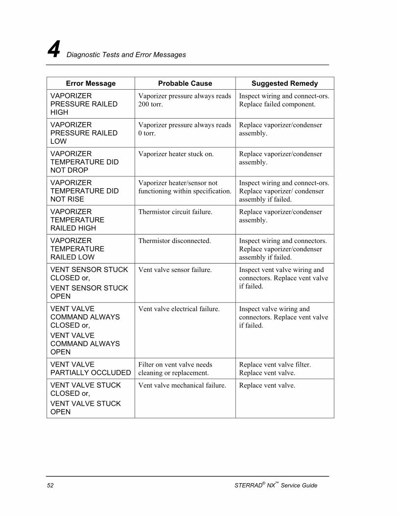
Error Message Probable Cause Suggested Remedy
VAPORIZER PRESSURE RAILED HIGH
Vaporizer pressure always reads 200 torr.
Inspect wiring and connect-ors. Replace failed component.
VAPORIZER PRESSURE RAILED LOW
Vaporizer pressure always reads 0 torr.
Replace vaporizer/condenser assembly.
VAPORIZER TEMPERATURE DID NOT DROP
Vaporizer heater stuck on. Replace vaporizer/condenser assembly.
VAPORIZER TEMPERATURE DID NOT RISE
Vaporizer heater/sensor not functioning within specification.
Inspect wiring and connect-ors. Replace vaporizer/ condenser assembly if failed.
VAPORIZER TEMPERATURE RAILED HIGH
Thermistor circuit failure. Replace vaporizer/condenser assembly.
VAPORIZER TEMPERATURE RAILED LOW
Thermistor disconnected. Inspect wiring and connectors. Replace vaporizer/condenser assembly if failed.
VENT SENSOR STUCK CLOSED or, VENT SENSOR STUCK OPEN
Vent valve sensor failure. Inspect vent valve wiring and connectors. Replace vent valve if failed.
VENT VALVE COMMAND ALWAYS CLOSED or, VENT VALVE COMMAND ALWAYS OPEN
Vent valve electrical failure. Inspect valve wiring and connectors. Replace vent valve if failed.
VENT VALVE PARTIALLY OCCLUDED
Filter on vent valve needs cleaning or replacement.
Replace vent valve filter. Replace vent valve.
VENT VALVE STUCK CLOSED or, VENT VALVE STUCK OPEN
Vent valve mechanical failure. Replace vent valve.
52 STERRAD® NX™ Service Guide
Subassembly Removal and Replacement 5
Chapter 5.
Subassembly Removal and Replacement
Access to Sterilizer Interior Service access to the interior of the sterilizer is obtained by removing top, front, or side panels. Many maintenance and service procedures require removal of only one or two panels. It is rarely necessary to remove all access panels.
STERRAD® NX™ Service Guide 53
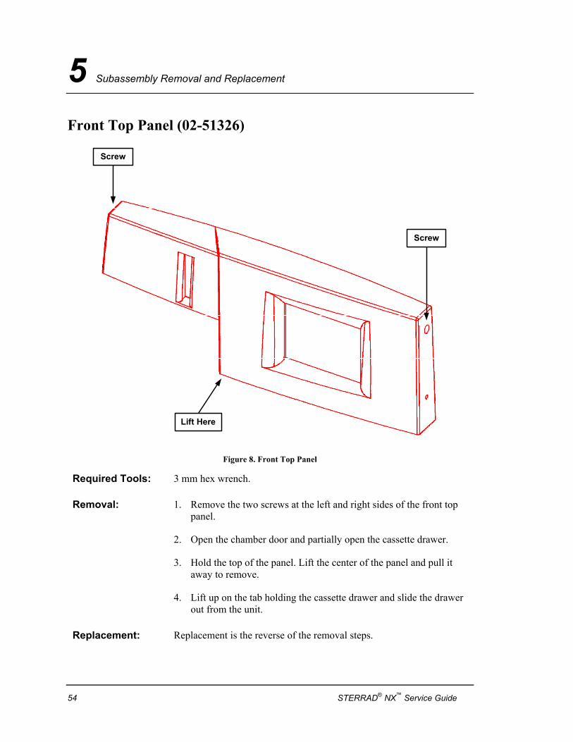
5 Subassembly Removal and Replacement
Front Top Panel (02-51326)
Screw
Screw
Lift Here
Figure 8. Front Top Panel
Required Tools: 3 mm hex wrench.
Removal: 1. Remove the two screws at the left and right sides of the front top panel.
2. Open the chamber door and partially open the cassette drawer.
3. Hold the top of the panel. Lift the center of the panel and pull it away to remove.
4. Lift up on the tab holding the cassette drawer and slide the drawer out from the unit.
Replacement: Replacement is the reverse of the removal steps.
54 STERRAD® NX™ Service Guide
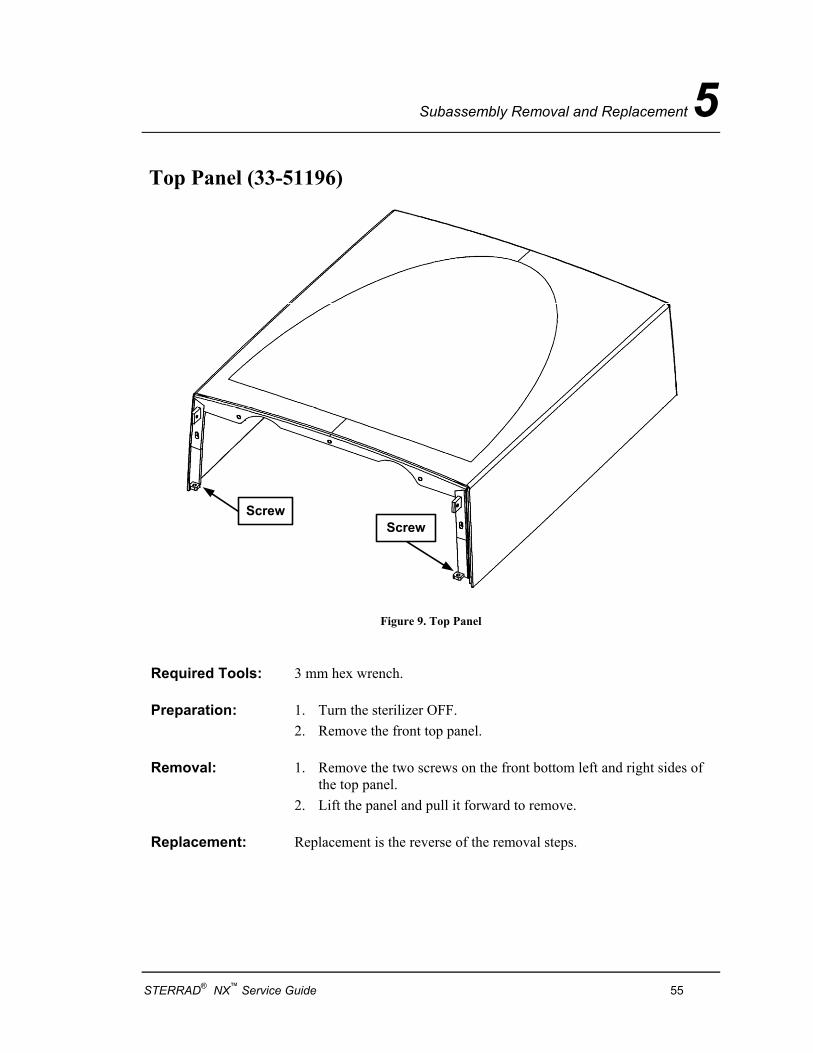
Subassembly Removal and Replacement 5
Top Panel (33-51196)
ScrewScrew
Figure 9. Top Panel
Required Tools: 3 mm hex wrench.
Preparation: 1. Turn the sterilizer OFF. 2. Remove the front top panel.
Removal: 1. Remove the two screws on the front bottom left and right sides of the top panel.
2. Lift the panel and pull it forward to remove.
Replacement: Replacement is the reverse of the removal steps.
STERRAD® NX™ Service Guide 55
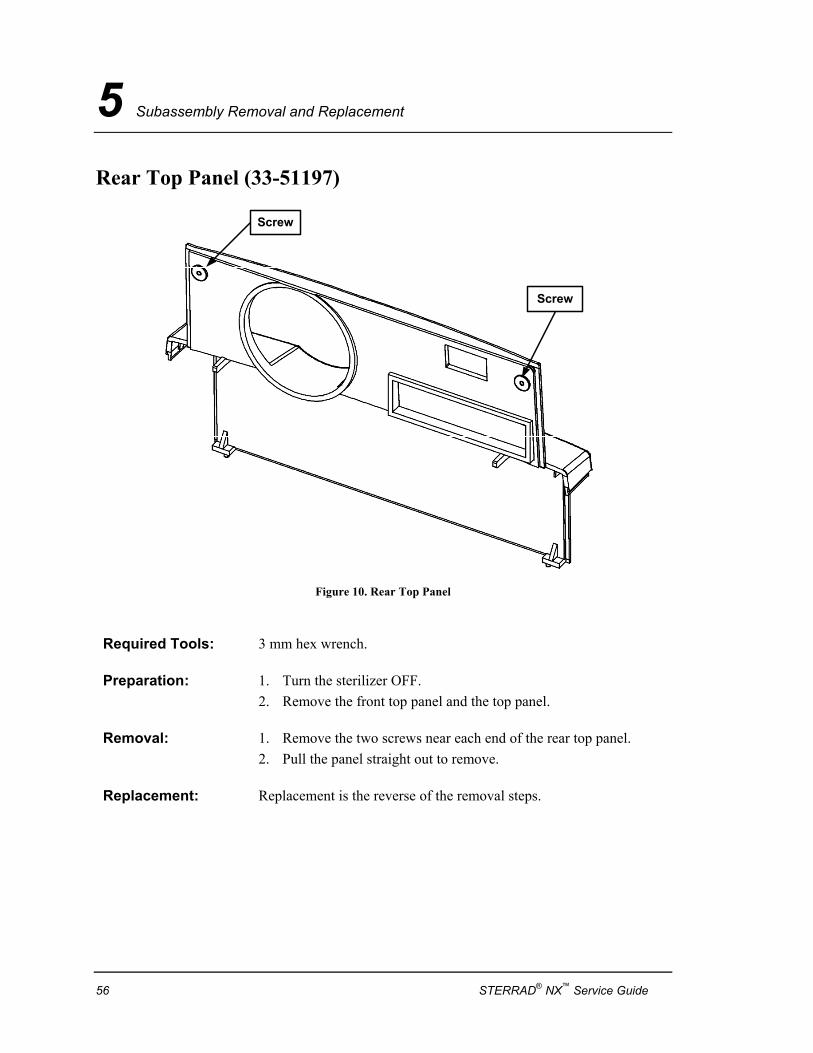
5 Subassembly Removal and Replacement
Rear Top Panel (33-51197)
Screw
Screw
Figure 10. Rear Top Panel
Required Tools: 3 mm hex wrench.
Preparation: 1. Turn the sterilizer OFF. 2. Remove the front top panel and the top panel.
Removal: 1. Remove the two screws near each end of the rear top panel. 2. Pull the panel straight out to remove.
Replacement: Replacement is the reverse of the removal steps.
56 STERRAD® NX™ Service Guide
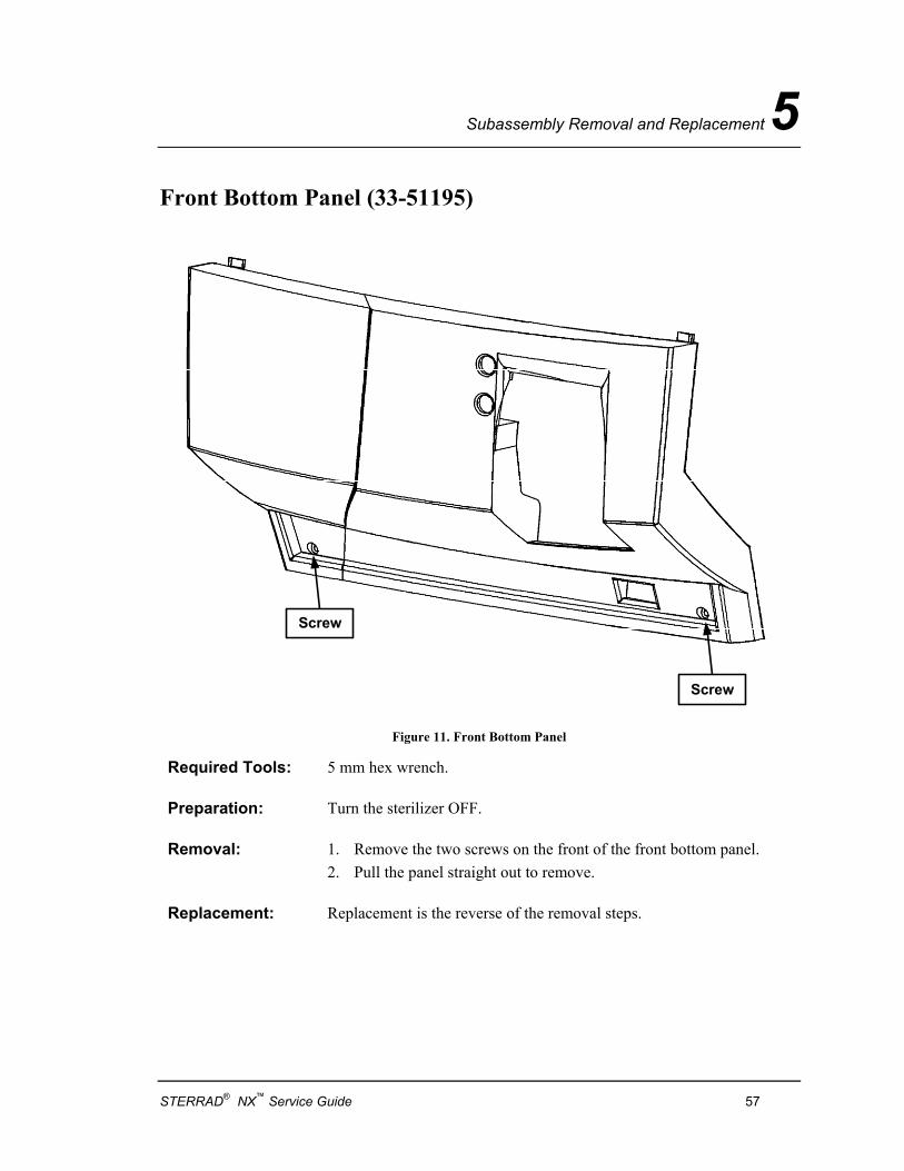
Subassembly Removal and Replacement 5
Front Bottom Panel (33-51195)
Screw
Screw
Figure 11. Front Bottom Panel
Required Tools: 5 mm hex wrench.
Preparation: Turn the sterilizer OFF.
Removal: 1. Remove the two screws on the front of the front bottom panel. 2. Pull the panel straight out to remove.
Replacement: Replacement is the reverse of the removal steps.
STERRAD® NX™ Service Guide 57
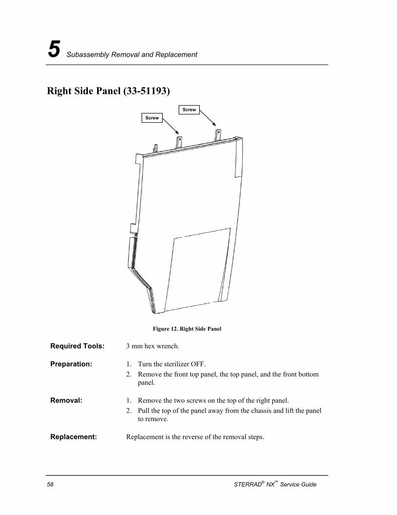
5 Subassembly Removal and Replacement
Right Side Panel (33-51193)
Screw
Screw
Figure 12. Right Side Panel
Required Tools: 3 mm hex wrench.
Preparation: 1. Turn the sterilizer OFF. 2. Remove the front top panel, the top panel, and the front bottom
panel.
Removal: 1. Remove the two screws on the top of the right panel. 2. Pull the top of the panel away from the chassis and lift the panel
to remove.
Replacement: Replacement is the reverse of the removal steps.
58 STERRAD® NX™ Service Guide
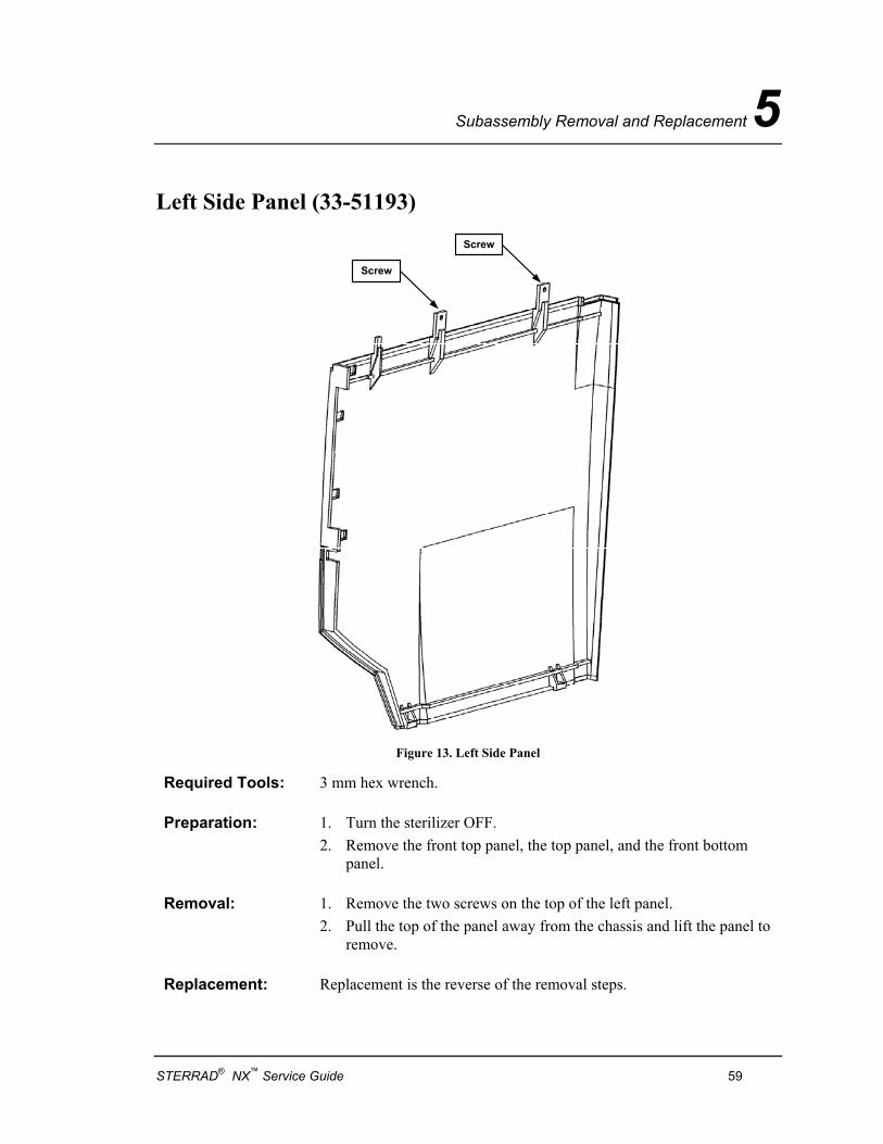
Subassembly Removal and Replacement 5
Left Side Panel (33-51193)
Screw
Screw
Figure 13. Left Side Panel
Required Tools: 3 mm hex wrench.
Preparation: 1. Turn the sterilizer OFF. 2. Remove the front top panel, the top panel, and the front bottom
panel.
Removal: 1. Remove the two screws on the top of the left panel. 2. Pull the top of the panel away from the chassis and lift the panel to
remove.
Replacement: Replacement is the reverse of the removal steps.
STERRAD® NX™ Service Guide 59
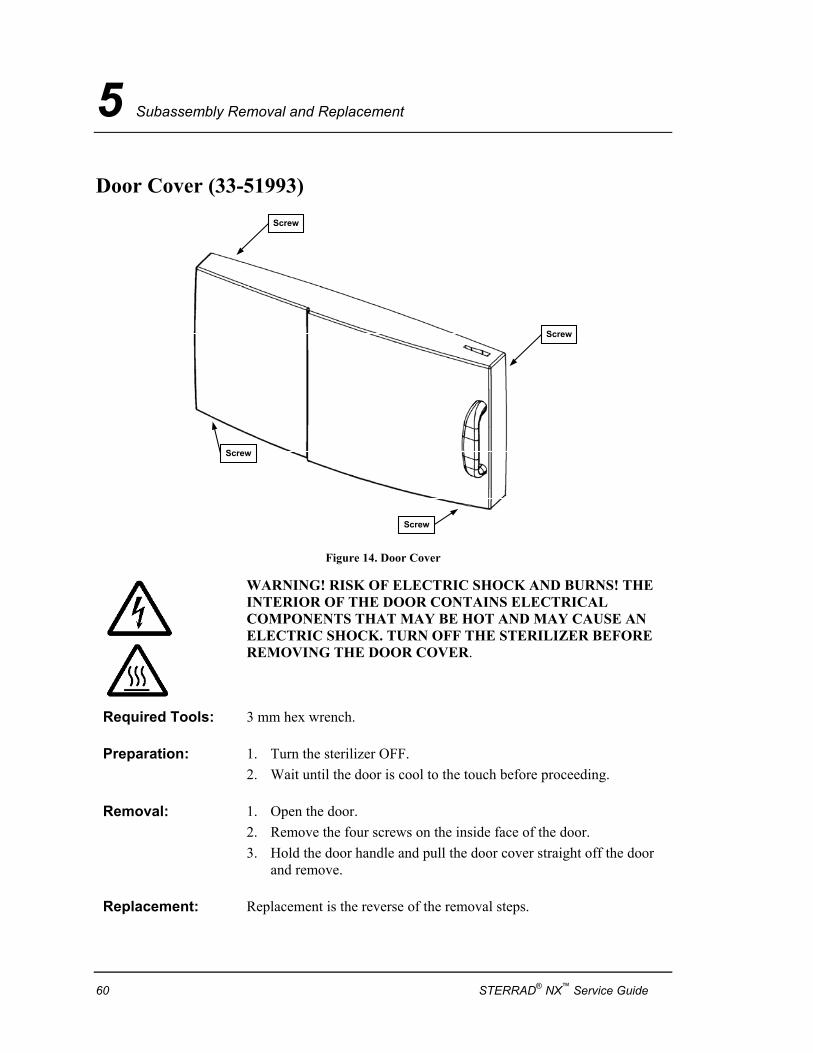
5 Subassembly Removal and Replacement
Door Cover (33-51993) Screw
Screw
Screw
Screw
Figure 14. Door Cover
WARNING! RISK OF ELECTRIC SHOCK AND BURNS! THE INTERIOR OF THE DOOR CONTAINS ELECTRICAL COMPONENTS THAT MAY BE HOT AND MAY CAUSE AN ELECTRIC SHOCK. TURN OFF THE STERILIZER BEFORE REMOVING THE DOOR COVER.
Required Tools: 3 mm hex wrench.
Preparation: 1. Turn the sterilizer OFF. 2. Wait until the door is cool to the touch before proceeding.
Removal: 1. Open the door. 2. Remove the four screws on the inside face of the door. 3. Hold the door handle and pull the door cover straight off the door
and remove.
Replacement: Replacement is the reverse of the removal steps.
60 STERRAD® NX™ Service Guide
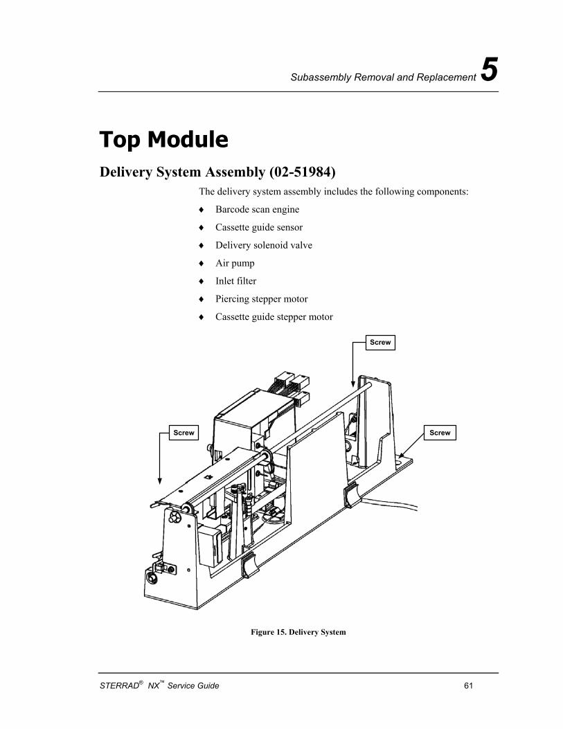
Subassembly Removal and Replacement 5
Top Module Delivery System Assembly (02-51984)
The delivery system assembly includes the following components:
♦ Barcode scan engine
♦ Cassette guide sensor
♦ Delivery solenoid valve
♦ Air pump
♦ Inlet filter
♦ Piercing stepper motor
♦ Cassette guide stepper motor
Screw
Screw
Screw
Figure 15. Delivery System
STERRAD® NX™ Service Guide 61
5 Subassembly Removal and Replacement
WARNING! RISK OF HYDROGEN PEROXIDE EXPOSURE. TRAPPED CASSETTES, NEEDLES, AND DELIVERY SYSTEM TUBING MAY CONTAIN HYDROGEN PEROXIDE. USE APPROVED PERSONAL PROTECTION EQUIPMENT (PPE) INCLUDING EYE PROTECTION AND GLOVES WHEN HANDLING THESE COMPONENTS.
Required Tools: 3 mm hex wrench.
Preparation: 1. If a cassette is loaded in the delivery system, use the menu commands to dispose of the cassette.
2. If a cassette is trapped in the delivery system and cannot be disposed of automatically, put on approved PPE (gloves and eye protection) before proceeding.
3. Open the cassette drawer and remove the box of disposed cassettes if present. You may remove the drawer if needed by pulling up the tab at the back of the drawer and sliding the drawer out.
4. Remove the front top panel and the top panel.
Removal: 1. If a cassette is trapped in the carriage, slowly turn the lead screw and/or piercing mechanism by hand until the cassette is released. Handle and discard the cassette safely.
2. Remove the needle carriage shroud. 3. Slide the carriage on its lead screw toward the rear of the sterilizer
to cover the piercing needles. 4. Unscrew and disconnect the tube that connects the bottom needle
to the vaporizer. 5. Unplug five cables: P138, P129, P130, P131, and P132. 6. Unplug the ribbon cable from the barcode scan engine. 7. Remove the three screws that attach the delivery system assembly
to the chassis. Two screws are near the rear and one is near the front.
8. Slide the assembly forward and lift it up to remove.
Replacement: Replacement is the reverse of the removal steps.
62 STERRAD® NX™ Service Guide
Subassembly Removal and Replacement 5
Delivery Valve Required Tools: Small pick
Preparation: 1. Turn the sterilizer OFF. 2. Remove the front top panel and the top panel. 3. Remove the delivery system from the sterilizer.
Removal: 1. Unscrew and disconnect P128 from the delivery valve. 2. Using the small pick, remove the 2 gaskets from the inside of the
fitting.
Replacement: Replacement is the reverse of the removal steps. Note that new gaskets come with the valve.
Delivery Subsystem Inlet Filter (PM kit part 25-50703) This is a PM procedure.
Required Tools: 3 mm hex wrench.
Preparation: 1. Open the cassette drawer and remove the box of disposed cassettes if present.
2. Remove the front top panel and the top panel.
Removal: 1. Slide the carriage on its lead screw toward the rear of the sterilizer to cover the piercing needles.
2. Unscrew and disconnect the inlet filter cartridge. 3. Connect a new inlet filter to the inlet fitting.
Replacement: Replacement is the reverse of the removal steps.
Air Pump Tubes This is a PM Procedure
Preparation: Remove the needle shroud.
Removal: 1. Unscrew the air pump from the bracket. 2. Remove the two tubes on the air pump.
Replacement: Replacement is the reverse of the removal steps.
STERRAD® NX™ Service Guide 63
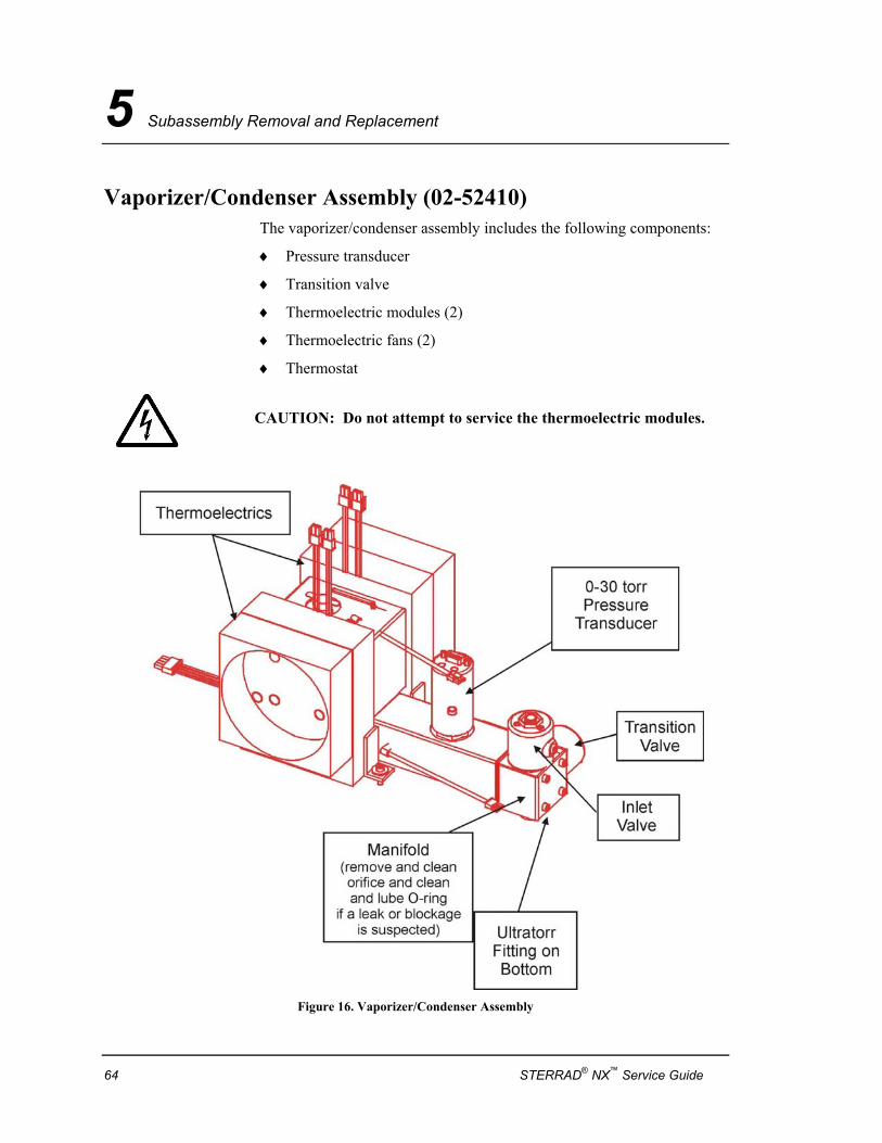
5 Subassembly Removal and Replacement
Vaporizer/Condenser Assembly (02-52410) The vaporizer/condenser assembly includes the following components:
♦ Pressure transducer
♦ Transition valve
♦ Thermoelectric modules (2)
♦ Thermoelectric fans (2)
♦ Thermostat
CAUTION: Do not attempt to service the thermoelectric modules.
Figure 16. Vaporizer/Condenser Assembly
64 STERRAD® NX™ Service Guide
Subassembly Removal and Replacement 5
WARNING! RISK OF HYDROGEN PEROXIDE EXPOSURE. THE VAPORIZER/CONDENSER SYSTEM MAY CONTAIN HYDROGEN PEROXIDE. USE APPROVED PERSONAL PROTECTION EQUIPMENT (PPE) INCLUDING EYE PROTECTION AND GLOVES WHEN HANDLING THESE COMPONENTS.
Required Tools: 3 mm hex wrench.
Soft-jaw pliers.
Preparation: Turn the sterilizer OFF. Remove the front top panel and the top panel.
4 Note: The assembly may not have pressure transducers attached. Remove the pressure transducer from the vaporizer/condenser assembly and retain it for installation on the new assembly. If a new pressure transducer is needed, it must be ordered separately.
Removal: 1. At the delivery system, disconnect the tube from the delivery system to the vaporizer/condenser.
2. Unplug 2 cables from the interface: J26 and J25. 3. Remove the two screws that attach the vaporizer/condenser
assembly to the chassis. 4. Use the soft-jaw pliers to unscrew the collar to the Ultratorr fitting. 5. Lift the vaporizer/condenser assembly up to remove. 6. Remove the spacer and the O-ring from inside the Ultratorr fitting.
Replacement: 1. Clean the inside of the Ultratorr fitting. 2. Lightly coat a new O-ring with approved vacuum grease and place
the O-ring in the Ultratorr fitting. 3. Reinstall the spacer in the Ultratorr fitting. 4. Reinstall the tubing onto the vaporizer. 5. Place the threaded collar around the base of the
vaporizer/condenser assembly and insert the tube into the Ultratorr fitting. Press down until it is seated firmly.
6. Use soft-jaw pliers to tighten the collar. 7. Install the retained pressure transducer. Replace and tighten the
two screws that attach the assembly to the chassis. 8. Reconnect the cables to the interface. 9. Reconnect the tube from the delivery system to the
vaporizer/condenser.
STERRAD® NX™ Service Guide 65
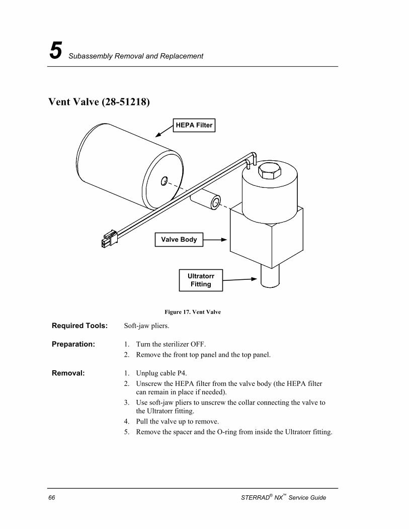
5 Subassembly Removal and Replacement
Vent Valve (28-51218)
HEPA Filter
UltratorrFitting
Valve Body
Figure 17. Vent Valve
Required Tools: Soft-jaw pliers.
Preparation: 1. Turn the sterilizer OFF. 2. Remove the front top panel and the top panel.
Removal: 1. Unplug cable P4. 2. Unscrew the HEPA filter from the valve body (the HEPA filter
can remain in place if needed). 3. Use soft-jaw pliers to unscrew the collar connecting the valve to
the Ultratorr fitting. 4. Pull the valve up to remove. 5. Remove the spacer and the O-ring from inside the Ultratorr fitting.
66 STERRAD® NX™ Service Guide
Subassembly Removal and Replacement 5
Replacement: 1. Clean the inside of the Ultratorr fitting. 2. Lightly coat a new O-ring with approved vacuum grease and place
the O-ring in the Ultratorr fitting. 3. Reinstall the spacer in the Ultratorr fitting. 4. Place the threaded collar around the base of the new valve and
insert the valve into the Ultratorr fitting. Press down until it is seated firmly.
5. Use the soft-jaw pliers to tighten the collar. 6. Wrap the threaded nipple on the valve body with new Teflon®
tape. 7. Screw the HEPA filter onto the threaded nipple. The filter should
be hand-tightened only. 8. Plug P4 into the valve connector.
Vent Valve HEPA Filter
Required Tools: Teflon® tape.
Preparation: 1. Turn the sterilizer OFF. 2. Remove the front top panel and the top panel.
Removal: Unscrew the HEPA filter from the valve body.
Replacement: 1. Wrap the threaded nipple on the valve body with new Teflon® tape.
2. Screw the HEPA filter onto the threaded nipple. The filter should be hand-tightened only.
Teflon® is a registered trademark of the DuPont Corporation.
STERRAD® NX™ Service Guide 67
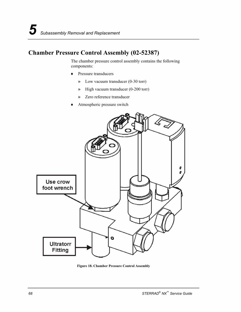
5 Subassembly Removal and Replacement
Chamber Pressure Control Assembly (02-52387) The chamber pressure control assembly contains the following components:
♦ Pressure transducers
» Low vacuum transducer (0-30 torr)
» High vacuum transducer (0-200 torr)
» Zero reference transducer
♦ Atmospheric pressure switch
Figure 18. Chamber Pressure Control Assembly
68 STERRAD® NX™ Service Guide
Subassembly Removal and Replacement 5
CAUTION: Do not torque the body of the transducer.
Required Tools: Soft-jaw pliers. Crow foot wrench
Preparation: 1. Turn the sterilizer OFF.
2. Remove the front top panel and the top panel.
Removal: 1. Unplug 4 cables: P5, P6, P9, and P13.
2. Use soft-jaw pliers to unscrew the collar connecting the manifold to the Ultratorr fitting.
3. Pull the manifold up to remove.
4. Remove the spacer and the O-ring from inside the Ultratorr fitting.
5. Use the crowfoot wrench to separately remove the pressure transducers.
Replacement: 1. Clean the inside of the Ultratorr fitting.
2. Lightly coat a new O-ring with approved vacuum grease and place the O-ring in the Ultratorr fitting.
3. Reinstall the spacer in the Ultratorr fitting.
4. Place the threaded collar around the base of the new manifold and insert the tube into the Ultratorr fitting. Press down until it is seated firmly.
5. Use soft-jaw pliers to tighten the collar.
6. Reconnect four cables: P5, P6, P9, and P13.
7. If the pressure transducers have been separately removed, replace them making sure the cables are correctly attached.
8. Perform a pressure transducer calibration.
STERRAD® NX™ Service Guide 69
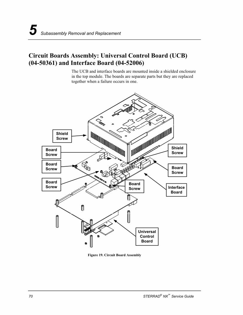
5 Subassembly Removal and Replacement
Circuit Boards Assembly: Universal Control Board (UCB) (04-50361) and Interface Board (04-52006)
The UCB and interface boards are mounted inside a shielded enclosure in the top module. The boards are separate parts but they are replaced together when a failure occurs in one.
ShieldScrew
ShieldScrew
BoardScrew
BoardScrew
BoardScrew
BoardScrew
BoardScrew
InterfaceBoard
UniversalControlBoard
Figure 19. Circuit Board Assembly
70 STERRAD® NX™ Service Guide
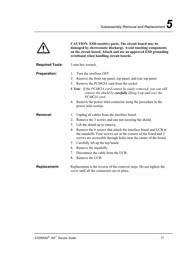
Subassembly Removal and Replacement 5
CAUTION: ESD-sensitive parts. The circuit board may be damaged by electrostatic discharge. Avoid touching components on the circuit board. Attach and use an approved ESD grounding wristband when handling circuit boards.
Required Tools: 3 mm hex wrench.
Preparation: 1. Turn the sterilizer OFF. 2. Remove the front top panel, top panel, and rear top panel. 3. Remove the PCMCIA card from the socket. 4 Note: If the PCMCIA card cannot be easily removed, you can still remove the shield by carefully lifting it up and over the PCMCIA card. 4. Remove the power inlet connector using the procedure in the
power inlet section.
Removal: 1. Unplug all cables from the interface board. 2. Remove the 3 screws and one nut securing the shield. 3. Lift the shield up to remove. 4. Remove the 6 screws that attach the interface board and UCB to
the standoffs. Four screws are at the corners of the board and 2 screws are accessible through holes near the center of the board.
5. Carefully lift up the top board. 6. Remove the standoffs. 7. Disconnect the cable from the UCB. 8. Remove the UCB
Replacement: Replacement is the reverse of the removal steps. Do not tighten the cover until all the connectors are in place.
STERRAD® NX™ Service Guide 71
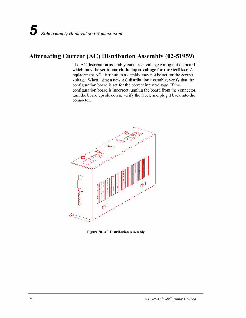
5 Subassembly Removal and Replacement
Alternating Current (AC) Distribution Assembly (02-51959) The AC distribution assembly contains a voltage configuration board which must be set to match the input voltage for the sterilizer. A replacement AC distribution assembly may not be set for the correct voltage. When using a new AC distribution assembly, verify that the configuration board is set for the correct input voltage. If the configuration board is incorrect, unplug the board from the connector, turn the board upside down, verify the label, and plug it back into the connector.
Figure 20. AC Distribution Assembly
72 STERRAD® NX™ Service Guide
Subassembly Removal and Replacement 5
WARNING! ELECTRIC SHOCK HAZARD. HAZARDOUS VOLTAGES ARE PRESENT INSIDE THE AC DISTRIBUTION ASSEMBLY. TURN THE STERILIZER OFF BEFORE HANDLING OR OPENING THE AC DISTRIBUTION ASSEMBLY.
Required Tools: 3 mm hex wrench.
Preparation: 1. Turn the sterilizer OFF. 2. Remove the front top panel and the top panel.
Removal: 1. Unplug five cables on the top of the box: P1, P2, P3, P5, and P6. 2. Unplug control cable P37 from the front of the box. Unplug the
ground. 3. Remove the two screws that attach the front edge of the box to the
chassis. 4. The box is held down by a keyed slot and stud. Slide the box
toward the front of the sterilizer, then lift to remove.
Replacement: 1. Open the new AC distribution assembly box and inspect the input voltage configuration board. If necessary, set the board to conform to the correct input voltage (120 V or 240 V). The configuration board indicates the voltage configuration when it is plugged in. The unit ships with the low voltage configuration.
2. Replacement is the reverse of the removal steps.
STERRAD® NX™ Service Guide 73
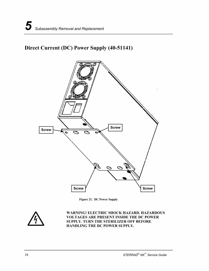
5 Subassembly Removal and Replacement
Direct Current (DC) Power Supply (40-51141)
ScrewScrew
Screw Screw
Figure 21. DC Power Supply
WARNING! ELECTRIC SHOCK HAZARD. HAZARDOUS VOLTAGES ARE PRESENT INSIDE THE DC POWER SUPPLY. TURN THE STERILIZER OFF BEFORE HANDLING THE DC POWER SUPPLY.
74 STERRAD® NX™ Service Guide
Subassembly Removal and Replacement 5
Required Tools: 3 mm hex wrench.
Preparation: 1. Turn the sterilizer OFF 2. Remove the front top panel and the top panel. 3. Remove the UCB/interface side cover.
Removal: 1. Unplug two cables: P6 and P44. 2. Move the outside edge of the power supply cover to expose the
screw head. 3. Remove four screws that attach the DC power supply to the
chassis. 4. Lift the DC power supply up to remove.
Replacement: Replacement is the reverse of the removal steps.
STERRAD® NX™ Service Guide 75
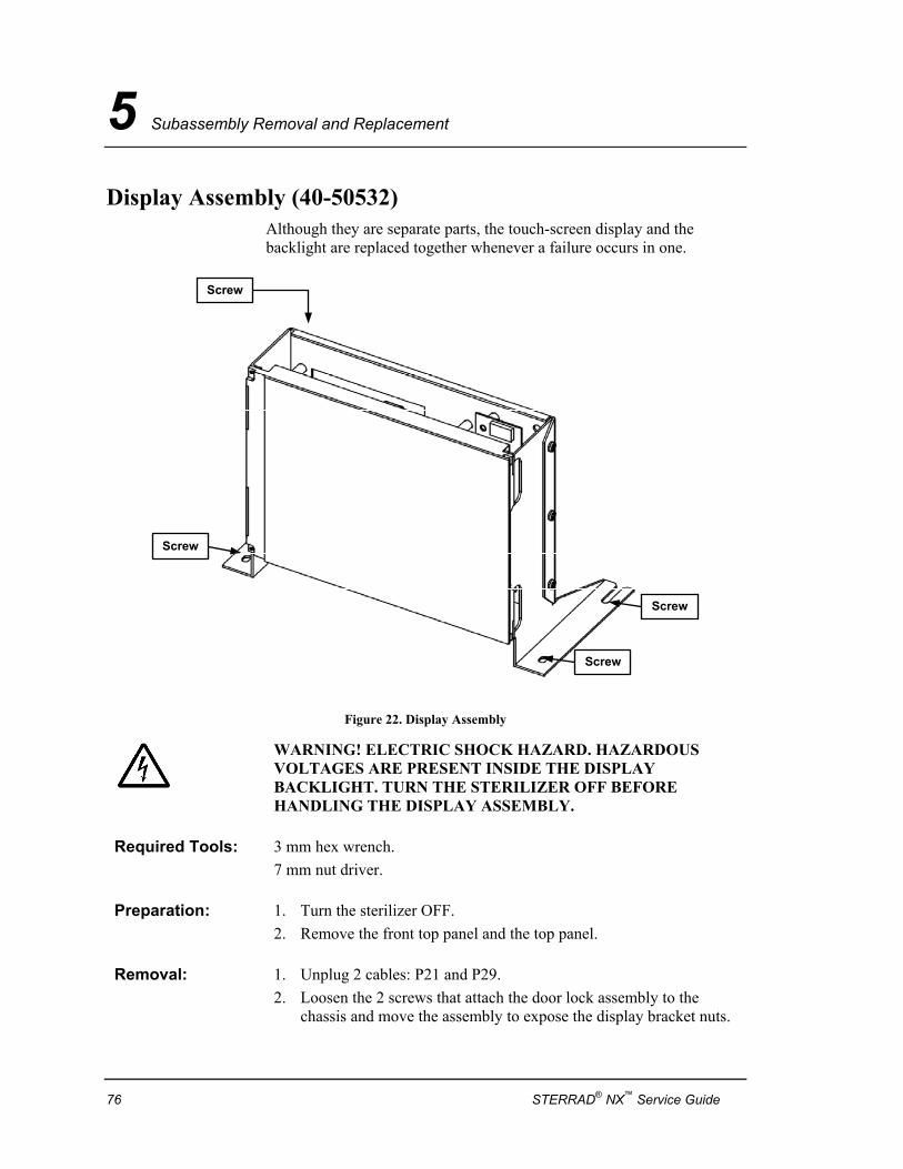
5 Subassembly Removal and Replacement
Display Assembly (40-50532) Although they are separate parts, the touch-screen display and the backlight are replaced together whenever a failure occurs in one.
Screw
Screw
Screw
Screw
Figure 22. Display Assembly
WARNING! ELECTRIC SHOCK HAZARD. HAZARDOUS VOLTAGES ARE PRESENT INSIDE THE DISPLAY BACKLIGHT. TURN THE STERILIZER OFF BEFORE HANDLING THE DISPLAY ASSEMBLY.
Required Tools: 3 mm hex wrench. 7 mm nut driver.
Preparation: 1. Turn the sterilizer OFF. 2. Remove the front top panel and the top panel.
Removal: 1. Unplug 2 cables: P21 and P29. 2. Loosen the 2 screws that attach the door lock assembly to the
chassis and move the assembly to expose the display bracket nuts.
76 STERRAD® NX™ Service Guide
Subassembly Removal and Replacement 5
3. Remove four nuts and washers that attach the display assembly bracket to threaded studs on the chassis.
4. Lift the display assembly up off the studs and forward to remove.
Replacement: Replacement is the reverse of the removal steps.
STERRAD® NX™ Service Guide 77
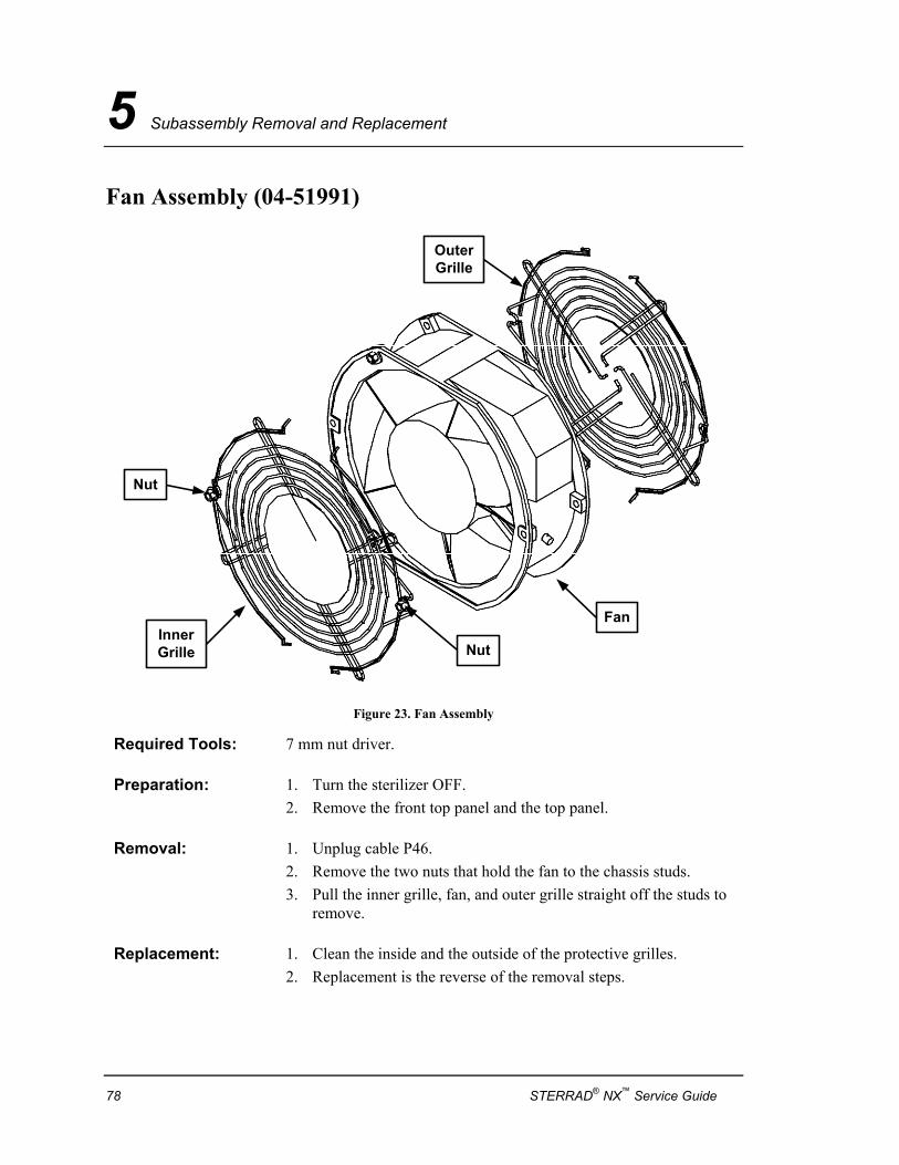
5 Subassembly Removal and Replacement
Fan Assembly (04-51991)
Nut
FanInnerGrille
OuterGrille
Nut
Figure 23. Fan Assembly
Required Tools: 7 mm nut driver.
Preparation: 1. Turn the sterilizer OFF. 2. Remove the front top panel and the top panel.
Removal: 1. Unplug cable P46. 2. Remove the two nuts that hold the fan to the chassis studs. 3. Pull the inner grille, fan, and outer grille straight off the studs to
remove.
Replacement: 1. Clean the inside and the outside of the protective grilles. 2. Replacement is the reverse of the removal steps.
78 STERRAD® NX™ Service Guide
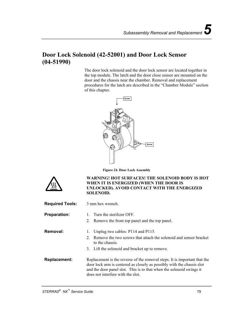
Subassembly Removal and Replacement 5
Door Lock Solenoid (42-52001) and Door Lock Sensor (04-51990)
The door lock solenoid and the door lock sensor are located together in the top module. The latch and the door close sensor are mounted on the door and the chassis near the chamber. Removal and replacement procedures for the latch are described in the “Chamber Module” section of this chapter.
Screw
Screw
Figure 24. Door Lock Assembly
WARNING! HOT SURFACES! THE SOLENOID BODY IS HOT WHEN IT IS ENERGIZED (WHEN THE DOOR IS UNLOCKED). AVOID CONTACT WITH THE ENERGIZED SOLENOID.
Required Tools: 3 mm hex wrench.
Preparation: 1. Turn the sterilizer OFF. 2. Remove the front top panel and the top panel.
Removal: 1. Unplug two cables: P114 and P115. 2. Remove the two screws that attach the solenoid and sensor bracket
to the chassis. 3. Lift the solenoid and bracket up to remove.
Replacement: Replacement is the reverse of the removal steps. It is important that the door lock arm is centered as closely as possibly with the chassis slot and the door panel slot. This is to that when the solenoid swings it does not interfere with the slot.
STERRAD® NX™ Service Guide 79
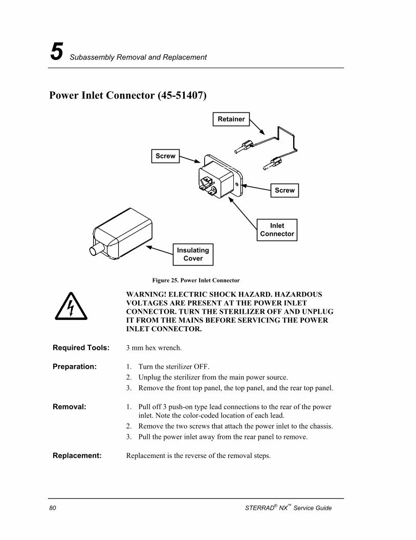
5 Subassembly Removal and Replacement
Power Inlet Connector (45-51407)
Screw
Screw
InsulatingCover
InletConnector
Retainer
Figure 25. Power Inlet Connector
WARNING! ELECTRIC SHOCK HAZARD. HAZARDOUS VOLTAGES ARE PRESENT AT THE POWER INLET CONNECTOR. TURN THE STERILIZER OFF AND UNPLUG IT FROM THE MAINS BEFORE SERVICING THE POWER INLET CONNECTOR.
Required Tools: 3 mm hex wrench.
Preparation: 1. Turn the sterilizer OFF. 2. Unplug the sterilizer from the main power source. 3. Remove the front top panel, the top panel, and the rear top panel.
Removal: 1. Pull off 3 push-on type lead connections to the rear of the power inlet. Note the color-coded location of each lead.
2. Remove the two screws that attach the power inlet to the chassis. 3. Pull the power inlet away from the rear panel to remove.
Replacement: Replacement is the reverse of the removal steps.
80 STERRAD® NX™ Service Guide
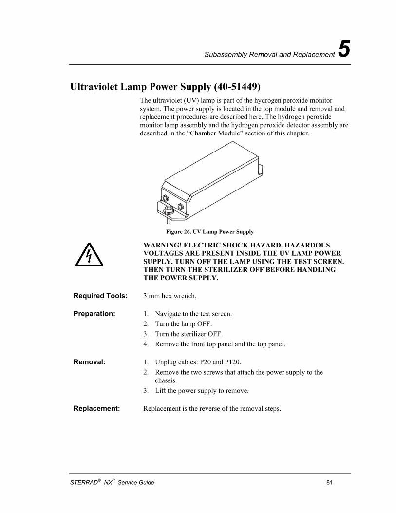
Subassembly Removal and Replacement 5
Ultraviolet Lamp Power Supply (40-51449) The ultraviolet (UV) lamp is part of the hydrogen peroxide monitor system. The power supply is located in the top module and removal and replacement procedures are described here. The hydrogen peroxide monitor lamp assembly and the hydrogen peroxide detector assembly are described in the “Chamber Module” section of this chapter.
Figure 26. UV Lamp Power Supply
WARNING! ELECTRIC SHOCK HAZARD. HAZARDOUS VOLTAGES ARE PRESENT INSIDE THE UV LAMP POWER SUPPLY. TURN OFF THE LAMP USING THE TEST SCREEN. THEN TURN THE STERILIZER OFF BEFORE HANDLING THE POWER SUPPLY.
Required Tools: 3 mm hex wrench.
Preparation: 1. Navigate to the test screen. 2. Turn the lamp OFF. 3. Turn the sterilizer OFF. 4. Remove the front top panel and the top panel.
Removal: 1. Unplug cables: P20 and P120. 2. Remove the two screws that attach the power supply to the
chassis. 3. Lift the power supply to remove.
Replacement: Replacement is the reverse of the removal steps.
STERRAD® NX™ Service Guide 81
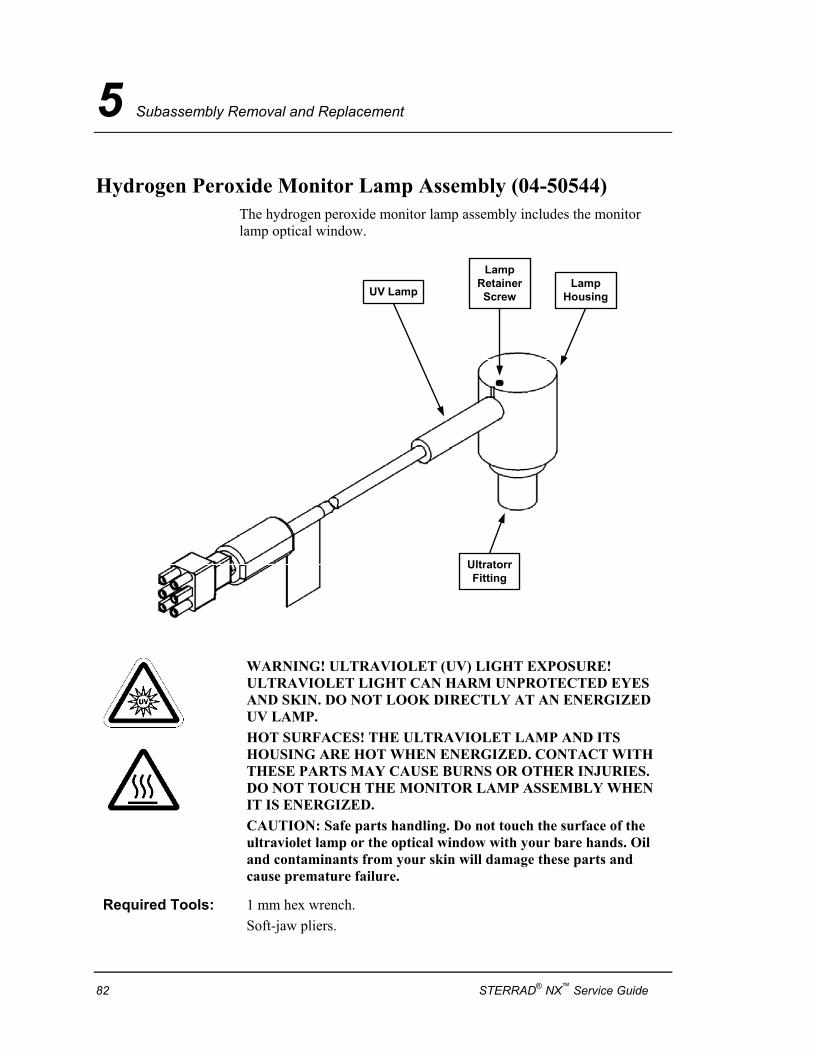
5 Subassembly Removal and Replacement
Hydrogen Peroxide Monitor Lamp Assembly (04-50544) The hydrogen peroxide monitor lamp assembly includes the monitor lamp optical window.
LampRetainerScrew
UltratorrFitting
UV LampLamp
Housing
WARNING! ULTRAVIOLET (UV) LIGHT EXPOSURE! ULTRAVIOLET LIGHT CAN HARM UNPROTECTED EYES AND SKIN. DO NOT LOOK DIRECTLY AT AN ENERGIZED UV LAMP. HOT SURFACES! THE ULTRAVIOLET LAMP AND ITS HOUSING ARE HOT WHEN ENERGIZED. CONTACT WITH THESE PARTS MAY CAUSE BURNS OR OTHER INJURIES. DO NOT TOUCH THE MONITOR LAMP ASSEMBLY WHEN IT IS ENERGIZED. CAUTION: Safe parts handling. Do not touch the surface of the ultraviolet lamp or the optical window with your bare hands. Oil and contaminants from your skin will damage these parts and cause premature failure.
Required Tools: 1 mm hex wrench. Soft-jaw pliers.
82 STERRAD® NX™ Service Guide
Subassembly Removal and Replacement 5
Preparation: 1. Turn off the lamp. 2. Remove the front top panel and the top panel.
Removal: If you are removing just the lamp, use step 3 only.
1. Unplug cable P20. 2. Use soft-jaw pliers to unscrew the collar to the Ultratorr fitting. 3. Loosen, but do not remove the lamp retainer screw. Remove the
lamp. 4. Lift the lamp housing up to remove. 5. Remove the spacer and the O-ring from inside the Ultratorr fitting. 6. Insert a 1 mm hex wrench through the hole in the top of the lamp
housing to loosen the lamp retaining screw. 7. Gently pull the UV lamp and socket assembly out of the lamp
housing. 8. Unscrew the base of the lamp housing and remove the O-ring and
the optical window.
Replacement: If replacing just the lamp, use step 1 only.
1. Install a new UV lamp in the lamp housing. Making sure to align the mark on the lamp with the mark on the lamp housing. Replace the set screw and do not overtighten.
2. Install a new optical window and O-ring in the lamp housing (if necessary).
3. Clean the inside of the Ultratorr fitting. Lightly coat a new O-ring with approved vacuum grease and place the O-ring in the Ultratorr fitting. Reinstall the spacer in the Ultratorr fitting.
4. Place the threaded collar around the base of the lamp housing. Insert the lamp housing tube into the Ultratorr fitting. Press down until it is seated firmly.
5. Orient the lamp housing so that there is no interference with the lamp cable. Use soft-jaw pliers to tighten the collar.
6. Reconnect cable P20.
STERRAD® NX™ Service Guide 83
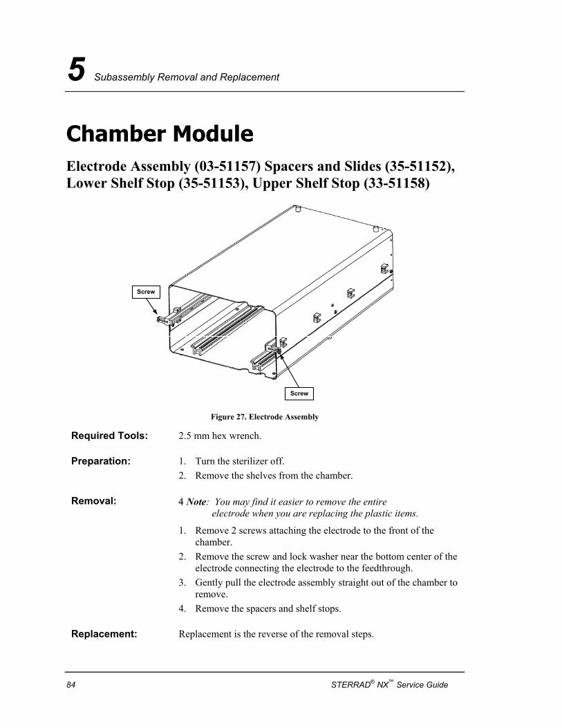
5 Subassembly Removal and Replacement
Chamber Module Electrode Assembly (03-51157) Spacers and Slides (35-51152), Lower Shelf Stop (35-51153), Upper Shelf Stop (33-51158)
Screw
Screw
Figure 27. Electrode Assembly
Required Tools: 2.5 mm hex wrench.
Preparation: 1. Turn the sterilizer off. 2. Remove the shelves from the chamber.
Removal: 4 Note: You may find it easier to remove the entire electrode when you are replacing the plastic items.
1. Remove 2 screws attaching the electrode to the front of the chamber.
2. Remove the screw and lock washer near the bottom center of the electrode connecting the electrode to the feedthrough.
3. Gently pull the electrode assembly straight out of the chamber to remove.
4. Remove the spacers and shelf stops.
Replacement: Replacement is the reverse of the removal steps.
84 STERRAD® NX™ Service Guide
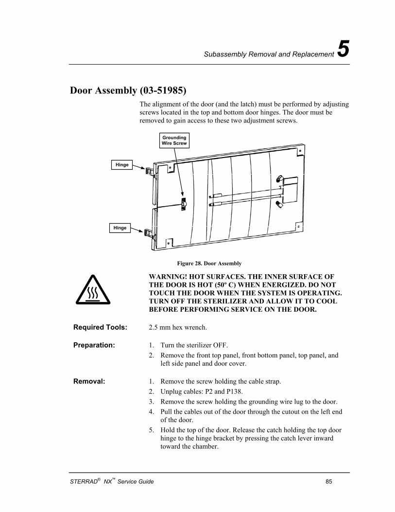
Subassembly Removal and Replacement 5
Door Assembly (03-51985) The alignment of the door (and the latch) must be performed by adjusting screws located in the top and bottom door hinges. The door must be removed to gain access to these two adjustment screws.
GroundingWire Screw
Hinge
Hinge
Figure 28. Door Assembly
WARNING! HOT SURFACES. THE INNER SURFACE OF THE DOOR IS HOT (50º C) WHEN ENERGIZED. DO NOT TOUCH THE DOOR WHEN THE SYSTEM IS OPERATING. TURN OFF THE STERILIZER AND ALLOW IT TO COOL BEFORE PERFORMING SERVICE ON THE DOOR.
Required Tools: 2.5 mm hex wrench.
Preparation: 1. Turn the sterilizer OFF. 2. Remove the front top panel, front bottom panel, top panel, and
left side panel and door cover.
Removal: 1. Remove the screw holding the cable strap. 2. Unplug cables: P2 and P138. 3. Remove the screw holding the grounding wire lug to the door. 4. Pull the cables out of the door through the cutout on the left end
of the door. 5. Hold the top of the door. Release the catch holding the top door
hinge to the hinge bracket by pressing the catch lever inward toward the chamber.
STERRAD® NX™ Service Guide 85
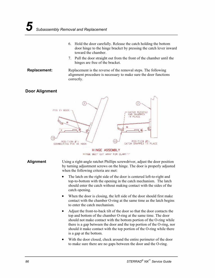
5 Subassembly Removal and Replacement
6. Hold the door carefully. Release the catch holding the bottom door hinge to the hinge bracket by pressing the catch lever inward toward the chamber.
7. Pull the door straight out from the front of the chamber until the hinges are free of the bracket.
Replacement: Replacement is the reverse of the removal steps. The following alignment procedure is necessary to make sure the door functions correctly.
Door Alignment
Alignment Using a right-angle ratchet Phillips screwdriver, adjust the door position by turning adjustment screws on the hinge. The door is properly adjusted when the following criteria are met: • The latch on the right side of the door is centered left-to-right and
top-to-bottom with the opening in the catch mechanism. The latch should enter the catch without making contact with the sides of the catch opening.
• When the door is closing, the left side of the door should first make contact with the chamber O-ring at the same time as the latch begins to enter the catch mechanism.
• Adjust the front-to-back tilt of the door so that the door contacts the top and bottom of the chamber O-ring at the same time. The door should not make contact with the bottom portion of the O-ring while there is a gap between the door and the top portion of the O-ring, nor should it make contact with the top portion of the O-ring while there is a gap at the bottom.
• With the door closed, check around the entire perimeter of the door to make sure there are no gaps between the door and the O-ring.
86 STERRAD® NX™ Service Guide
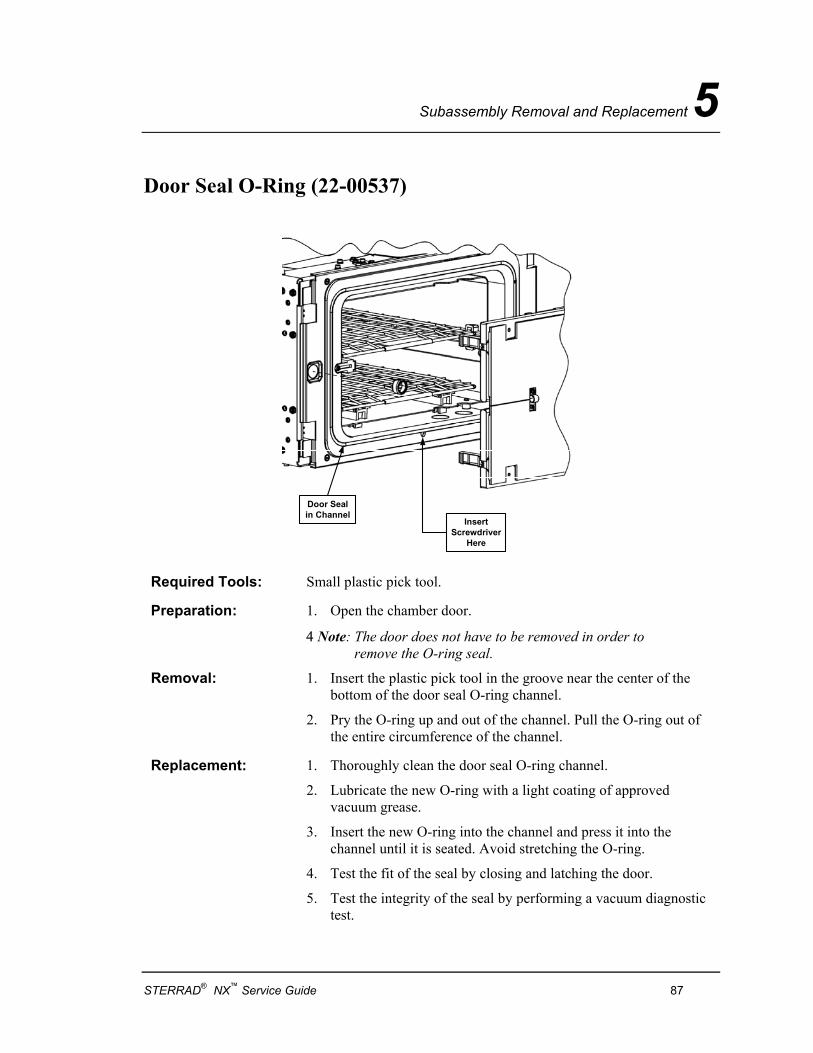
Subassembly Removal and Replacement 5
Door Seal O-Ring (22-00537)
InsertScrewdriver
Here
Door Sealin Channel
Required Tools: Small plastic pick tool.
Preparation: 1. Open the chamber door.
4 Note: The door does not have to be removed in order to remove the O-ring seal.
Removal: 1. Insert the plastic pick tool in the groove near the center of the bottom of the door seal O-ring channel.
2. Pry the O-ring up and out of the channel. Pull the O-ring out of the entire circumference of the channel.
Replacement: 1. Thoroughly clean the door seal O-ring channel.
2. Lubricate the new O-ring with a light coating of approved vacuum grease.
3. Insert the new O-ring into the channel and press it into the channel until it is seated. Avoid stretching the O-ring.
4. Test the fit of the seal by closing and latching the door.
5. Test the integrity of the seal by performing a vacuum diagnostic test.
STERRAD® NX™ Service Guide 87
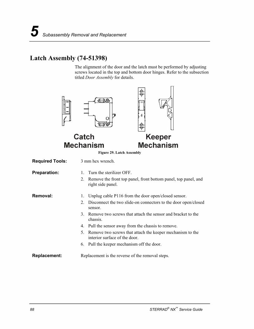
5 Subassembly Removal and Replacement
Latch Assembly (74-51398) The alignment of the door and the latch must be performed by adjusting screws located in the top and bottom door hinges. Refer to the subsection titled Door Assembly for details.
Figure 29. Latch Assembly
Required Tools: 3 mm hex wrench.
Preparation: 1. Turn the sterilizer OFF. 2. Remove the front top panel, front bottom panel, top panel, and
right side panel.
Removal: 1. Unplug cable P116 from the door open/closed sensor. 2. Disconnect the two slide-on connectors to the door open/closed
sensor. 3. Remove two screws that attach the sensor and bracket to the
chassis. 4. Pull the sensor away from the chassis to remove. 5. Remove two screws that attach the keeper mechanism to the
interior surface of the door. 6. Pull the keeper mechanism off the door.
Replacement: Replacement is the reverse of the removal steps.
88 STERRAD® NX™ Service Guide
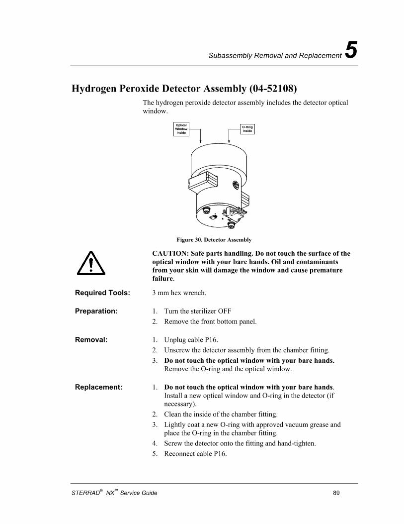
Subassembly Removal and Replacement 5
Hydrogen Peroxide Detector Assembly (04-52108) The hydrogen peroxide detector assembly includes the detector optical window.
O-RingInside
OpticalWindowInside
Figure 30. Detector Assembly
CAUTION: Safe parts handling. Do not touch the surface of the optical window with your bare hands. Oil and contaminants from your skin will damage the window and cause premature failure.
Required Tools: 3 mm hex wrench.
Preparation: 1. Turn the sterilizer OFF 2. Remove the front bottom panel.
Removal: 1. Unplug cable P16. 2. Unscrew the detector assembly from the chamber fitting. 3. Do not touch the optical window with your bare hands.
Remove the O-ring and the optical window.
Replacement: 1. Do not touch the optical window with your bare hands. Install a new optical window and O-ring in the detector (if necessary).
2. Clean the inside of the chamber fitting. 3. Lightly coat a new O-ring with approved vacuum grease and
place the O-ring in the chamber fitting. 4. Screw the detector onto the fitting and hand-tighten. 5. Reconnect cable P16.
STERRAD® NX™ Service Guide 89
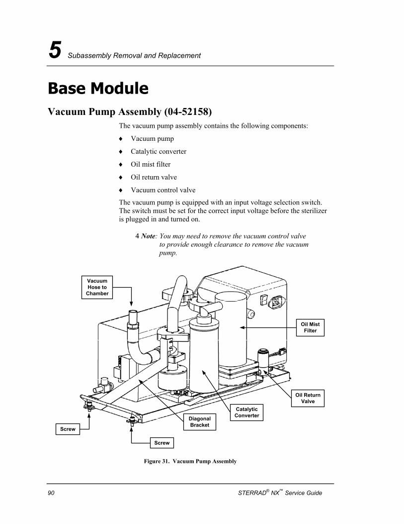
5 Subassembly Removal and Replacement
Base Module Vacuum Pump Assembly (04-52158)
The vacuum pump assembly contains the following components:
♦ Vacuum pump
♦ Catalytic converter
♦ Oil mist filter
♦ Oil return valve
♦ Vacuum control valve
The vacuum pump is equipped with an input voltage selection switch. The switch must be set for the correct input voltage before the sterilizer is plugged in and turned on.
4 Note: You may need to remove the vacuum control valve to provide enough clearance to remove the vacuum pump.
Screw
Screw
VacuumHose to
Chamber
Oil ReturnValve
Oil MistFilter
CatalyticConverterDiagonal
Bracket
Figure 31. Vacuum Pump Assembly
90 STERRAD® NX™ Service Guide
Subassembly Removal and Replacement 5
Required Tools: 3 mm hex wrench. 5 mm hex wrench.
Preparation: 1. Turn the sterilizer OFF. 2. Remove the front top panel, top panel, front bottom panel, and right
side panel.
Removal:
1. Unplug cable P6. 2. Remove the two screws that attach the diagonal bracket in front of the
vacuum subsystem to the chassis. 3. Remove two screws that secure the vacuum subsystem platform. 4. Disconnect the Twinax feedthrough cable from the bottom of the
feedthrough. 5. Disconnect the vacuum hose from the chamber. 6. Unplug two cables: P112 and P113.
WARNING! THE PUMP AND PLATFORM ARE VERY HEAVY (29.5 KG). USE CARE WHEN REMOVING
7. Grasp the front handle of the pump platform and pull the platform straight out. It will slide forward on guides. Use caution, the pump and platform weighs about 29.5 kg (65 lbs).
Replacement: Replacement is the reverse of the removal steps.
STERRAD® NX™ Service Guide 91
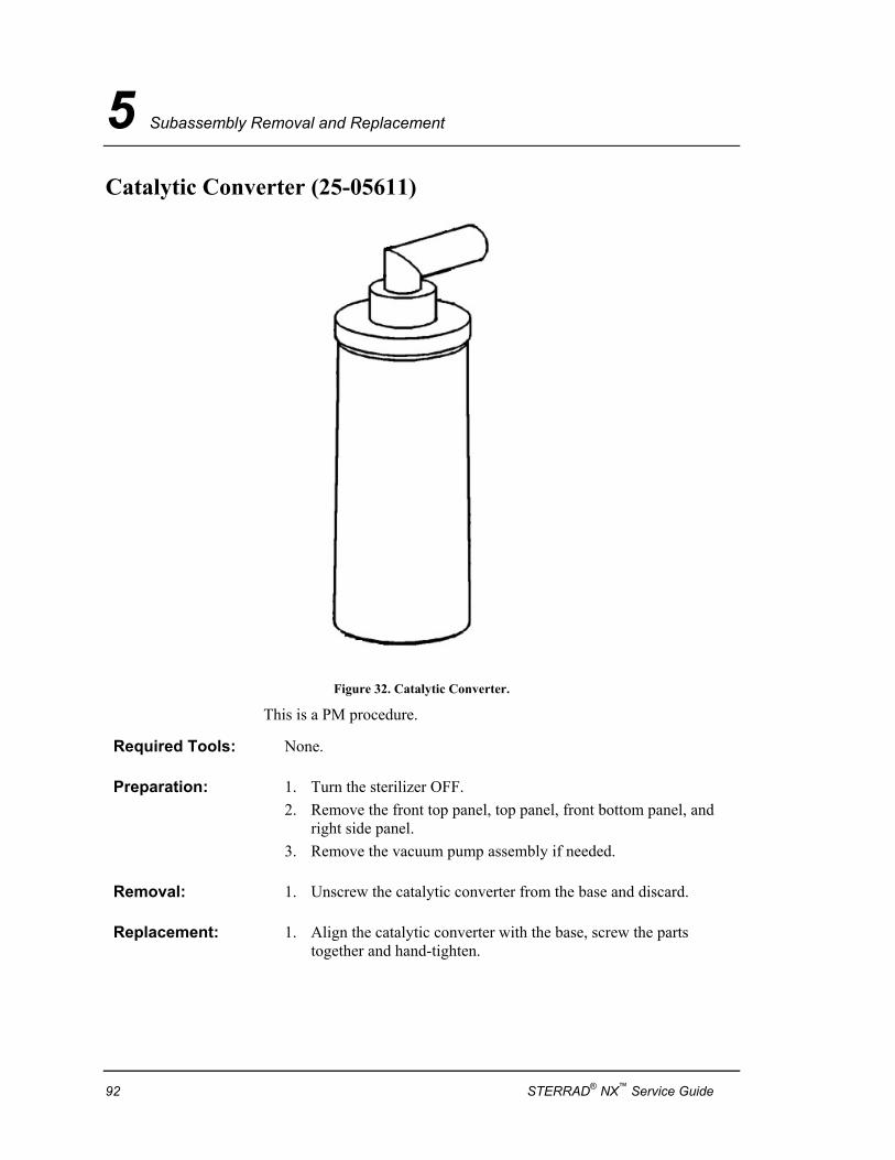
5 Subassembly Removal and Replacement
Catalytic Converter (25-05611)
Figure 32. Catalytic Converter.
This is a PM procedure.
Required Tools: None.
Preparation: 1. Turn the sterilizer OFF. 2. Remove the front top panel, top panel, front bottom panel, and
right side panel. 3. Remove the vacuum pump assembly if needed.
Removal: 1. Unscrew the catalytic converter from the base and discard.
Replacement: 1. Align the catalytic converter with the base, screw the parts together and hand-tighten.
92 STERRAD® NX™ Service Guide
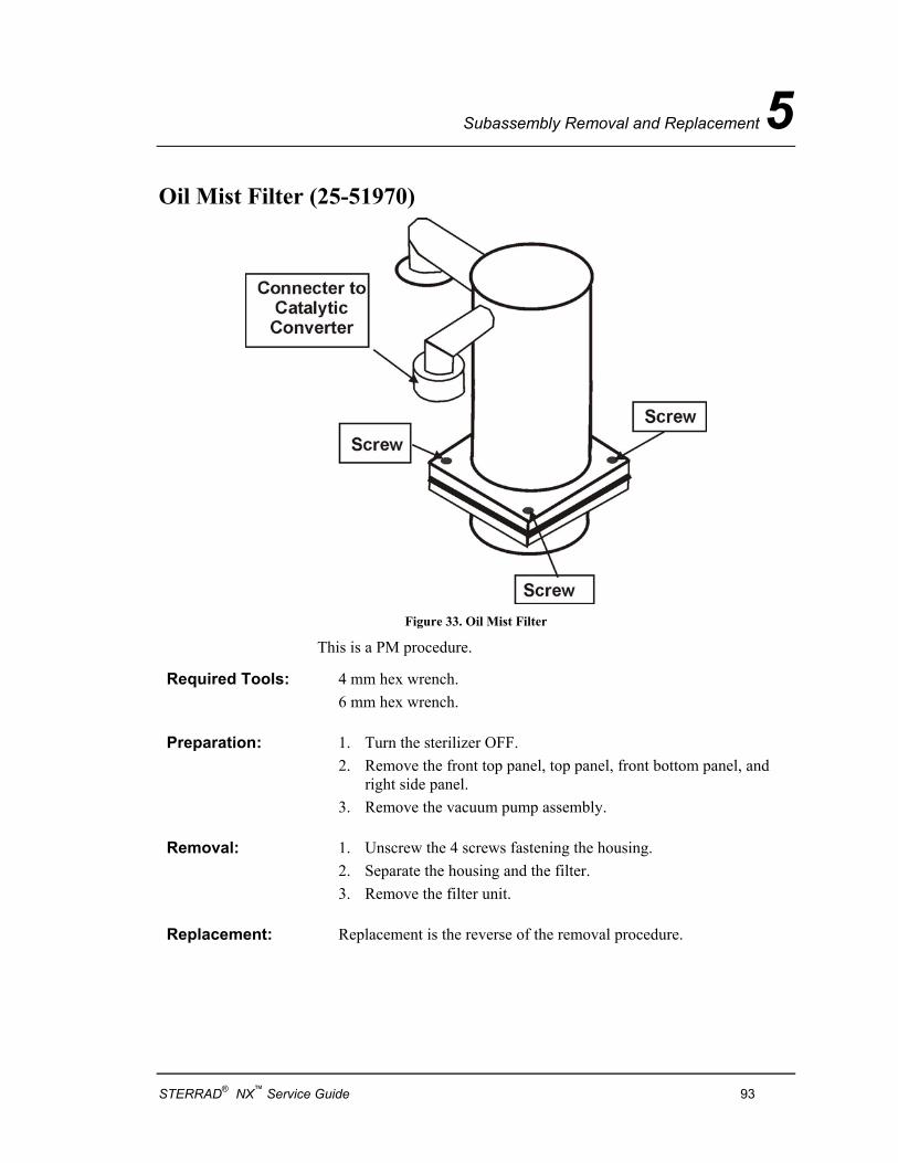
Subassembly Removal and Replacement 5
Oil Mist Filter (25-51970)
Figure 33. Oil Mist Filter
This is a PM procedure.
Required Tools: 4 mm hex wrench. 6 mm hex wrench.
Preparation: 1. Turn the sterilizer OFF. 2. Remove the front top panel, top panel, front bottom panel, and
right side panel. 3. Remove the vacuum pump assembly.
Removal: 1. Unscrew the 4 screws fastening the housing. 2. Separate the housing and the filter. 3. Remove the filter unit.
Replacement: Replacement is the reverse of the removal procedure.
STERRAD® NX™ Service Guide 93
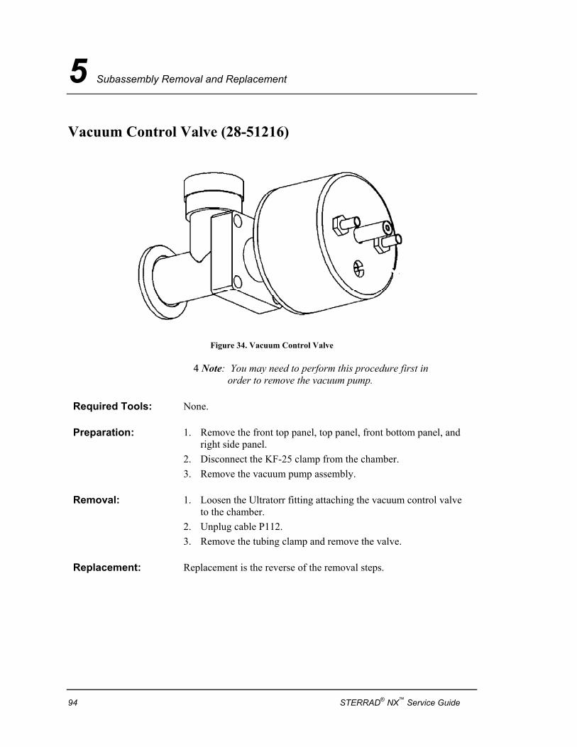
5 Subassembly Removal and Replacement
Vacuum Control Valve (28-51216)
Figure 34. Vacuum Control Valve
4 Note: You may need to perform this procedure first in order to remove the vacuum pump.
Required Tools: None.
Preparation: 1. Remove the front top panel, top panel, front bottom panel, and right side panel.
2. Disconnect the KF-25 clamp from the chamber. 3. Remove the vacuum pump assembly.
Removal: 1. Loosen the Ultratorr fitting attaching the vacuum control valve to the chamber.
2. Unplug cable P112. 3. Remove the tubing clamp and remove the valve.
Replacement: Replacement is the reverse of the removal steps.
94 STERRAD® NX™ Service Guide
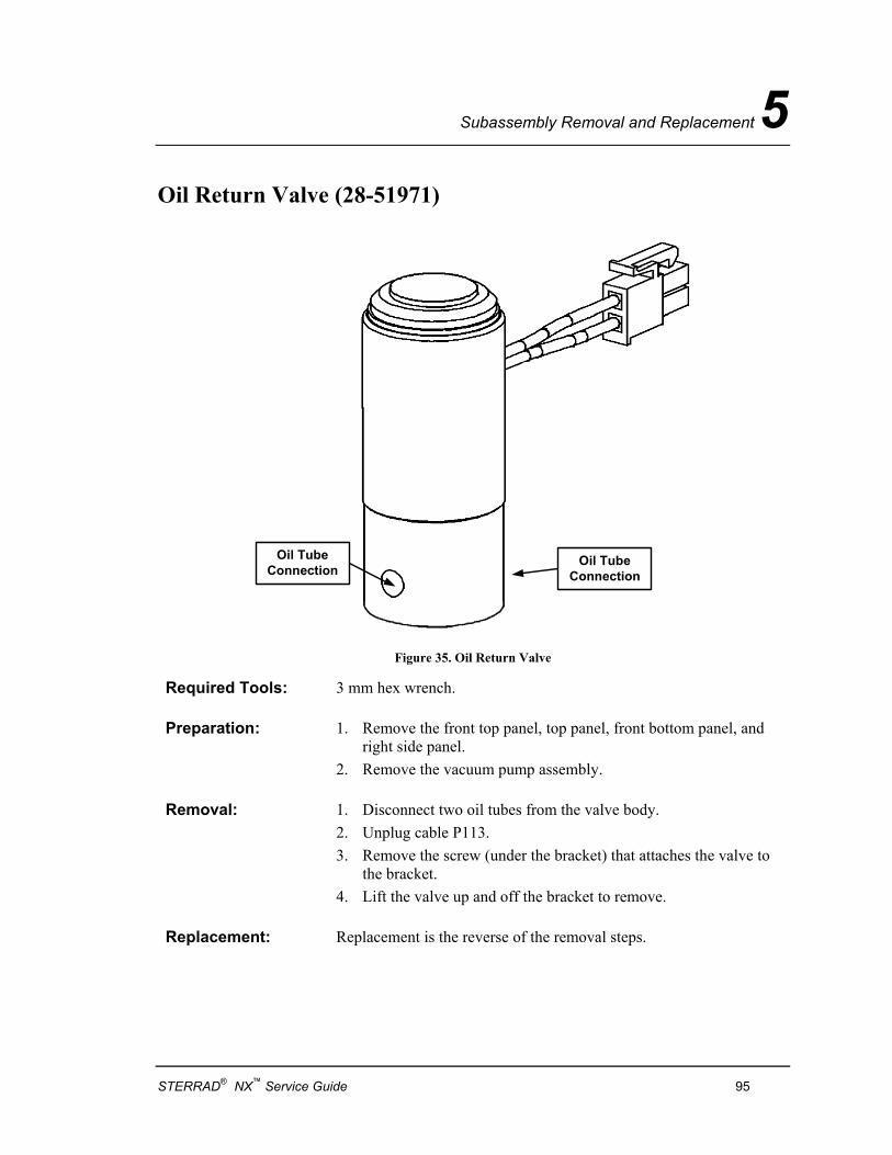
Subassembly Removal and Replacement 5
Oil Return Valve (28-51971)
Oil TubeConnection
Oil TubeConnection
Figure 35. Oil Return Valve
Required Tools: 3 mm hex wrench.
Preparation: 1. Remove the front top panel, top panel, front bottom panel, and right side panel.
2. Remove the vacuum pump assembly.
Removal: 1. Disconnect two oil tubes from the valve body. 2. Unplug cable P113. 3. Remove the screw (under the bracket) that attaches the valve to
the bracket. 4. Lift the valve up and off the bracket to remove.
Replacement: Replacement is the reverse of the removal steps.
STERRAD® NX™ Service Guide 95
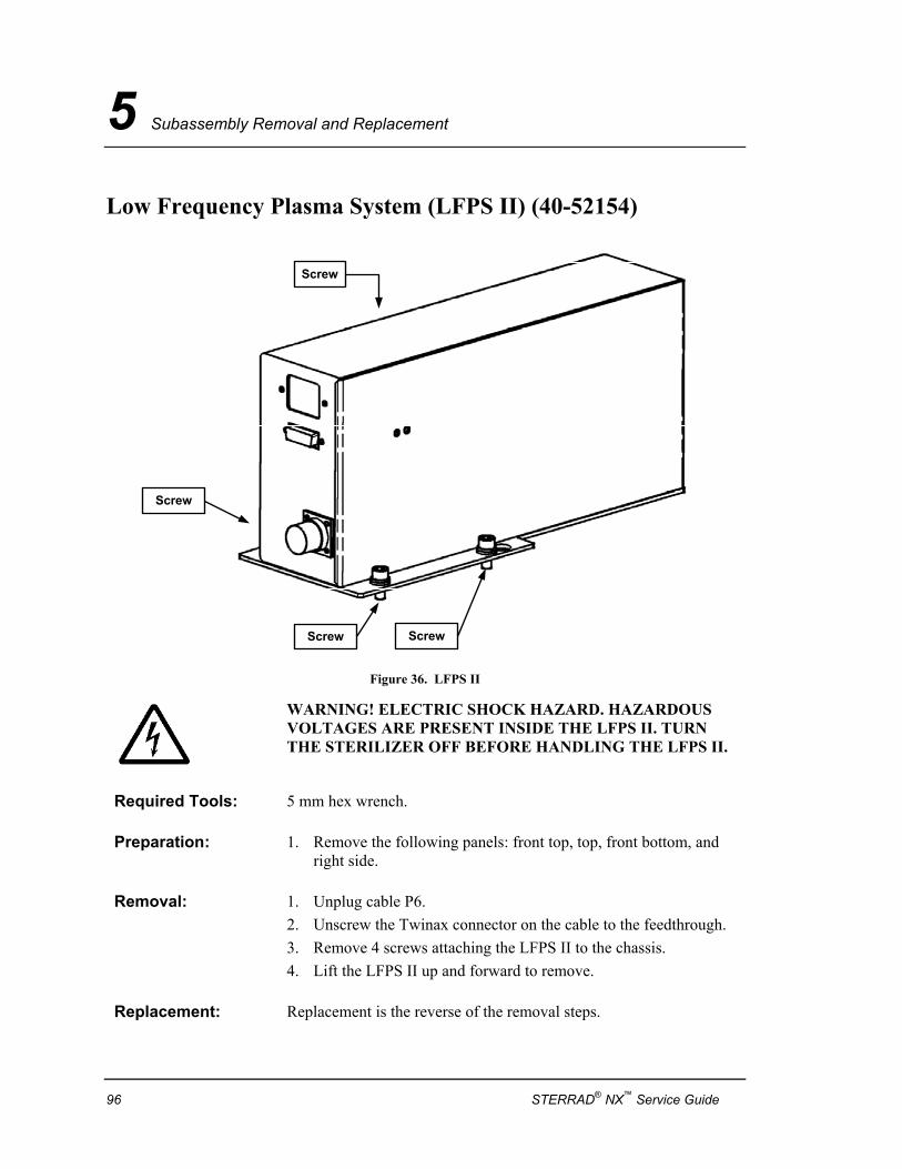
5 Subassembly Removal and Replacement
Low Frequency Plasma System (LFPS II) (40-52154)
Screw
Screw Screw
Screw
Figure 36. LFPS II
WARNING! ELECTRIC SHOCK HAZARD. HAZARDOUS VOLTAGES ARE PRESENT INSIDE THE LFPS II. TURN THE STERILIZER OFF BEFORE HANDLING THE LFPS II.
Required Tools: 5 mm hex wrench.
Preparation: 1. Remove the following panels: front top, top, front bottom, and right side.
Removal: 1. Unplug cable P6. 2. Unscrew the Twinax connector on the cable to the feedthrough. 3. Remove 4 screws attaching the LFPS II to the chassis. 4. Lift the LFPS II up and forward to remove.
Replacement: Replacement is the reverse of the removal steps.
96 STERRAD® NX™ Service Guide
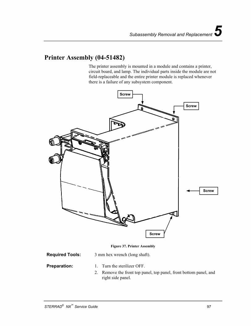
Subassembly Removal and Replacement 5
Printer Assembly (04-51482) The printer assembly is mounted in a module and contains a printer, circuit board, and lamp. The individual parts inside the module are not field-replaceable and the entire printer module is replaced whenever there is a failure of any subsystem component.
Screw
Screw
Screw
Screw
Figure 37. Printer Assembly
Required Tools: 3 mm hex wrench (long shaft).
Preparation: 1. Turn the sterilizer OFF. 2. Remove the front top panel, top panel, front bottom panel, and
right side panel.
STERRAD® NX™ Service Guide 97
5 Subassembly Removal and Replacement
Removal: 1. Unplug cable P17. 2. Remove the 4 screws attaching the printer module to the chassis.
Support the printer module as the last screw is removed. 3. Pull the printer module out and to the right to remove (avoid
contact with the hydrogen peroxide monitor detector).
Replacement: Replacement is the reverse of the removal steps.
98 STERRAD® NX™ Service Guide
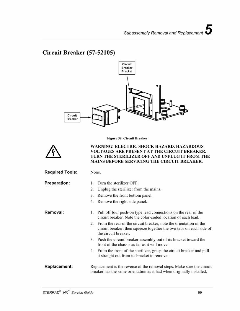
Subassembly Removal and Replacement 5
Circuit Breaker (57-52105)
CircuitBreaker
CircuitBreakerBracket
Figure 38. Circuit Breaker
WARNING! ELECTRIC SHOCK HAZARD. HAZARDOUS VOLTAGES ARE PRESENT AT THE CIRCUIT BREAKER. TURN THE STERILIZER OFF AND UNPLUG IT FROM THE MAINS BEFORE SERVICING THE CIRCUIT BREAKER.
Required Tools: None.
Preparation: 1. Turn the sterilizer OFF. 2. Unplug the sterilizer from the mains. 3. Remove the front bottom panel. 4. Remove the right side panel.
Removal: 1. Pull off four push-on type lead connections on the rear of the circuit breaker. Note the color-coded location of each lead.
2. From the rear of the circuit breaker, note the orientation of the circuit breaker, then squeeze together the two tabs on each side of the circuit breaker.
3. Push the circuit breaker assembly out of its bracket toward the front of the chassis as far as it will move.
4. From the front of the sterilizer, grasp the circuit breaker and pull it straight out from its bracket to remove.
Replacement: Replacement is the reverse of the removal steps. Make sure the circuit breaker has the same orientation as it had when originally installed.
STERRAD® NX™ Service Guide 99

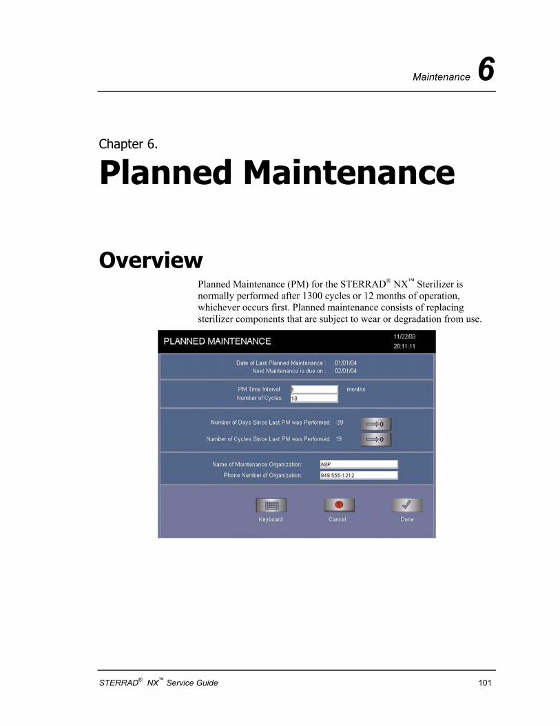
Maintenance 6
Chapter 6.
Planned Maintenance
Overview Planned Maintenance (PM) for the STERRAD® NX™ Sterilizer is normally performed after 1300 cycles or 12 months of operation, whichever occurs first. Planned maintenance consists of replacing sterilizer components that are subject to wear or degradation from use.
STERRAD® NX™ Service Guide 101
6 Maintenance
Vacuum Pump Oil Replacement All procedure on the vacuum pump can be performed with the pump in place if needed, otherwise, remove the vacuum pump and perform the procedures.
✔ Note: Always change the pump oil while the pump is warm to prevent condensation from remaining in the pump.
CAUTION: Do NOT slide the service tray all the way out. It will tip the pump over.
1. Unscrew and remove the oil fill plug located at the top of the pump.
✔ Note: The drain hose is in the PM kit.
2. Remove the cap from an empty oil bottle.. Place an oil absorbing cloth under the bottle and as close to the drain valve hose as possible. Place the bottle on the cloth. Place the hose in the bottle, open the drain valve and drain the oil.
3. After the flow has stopped, close the drain valve. Make sure the main circuit breaker is off before proceeding.
✔ ✔ Note: If the used pump oil is excessively dirty, flush out the pump according to the Vacuum Pump Flush procedure.
4. Open a new bottle of pump oil and replace the cap with the oil filler cap (red tipped). Remove the red tip and cut about 1/6 to 1/4 inch off the cap tip so the oil flows freely.
5. Pour new pump oil (slightly less than one quart) into the oil fill port until oil reaches between the top two fill marks. DO NOT OVER FILL or attempt to empty the oil bottle. Some oil may remain in the bottle when the pump oil is at the specified fill level.
6. Replace the oil fill plug. Re-cap and dispose of the drained oil and the oil absorbent cloth following standard hospital procedures.
102 STERRAD® NX™ Service Guide
Maintenance 6
Catalytic Converter Replacement 1. Unscrew the catalytic converter from the base and discard.
2. To install a new catalytic converter: align the converter with the base, screw the parts together and hand-tighten.
Oil Mist Filter Replacement 1. Unscrew the 4 screws fastening the housing to the vacuum pump.
2. Separate the housing and the filter.
3. Remove the filter element.
To install the new filter element, do the following:
4. Insert the new filter element in the housing.
5. Replace the housing and fasten the 4 screws.
Air Filter Replacement 1. Unscrew the nut from underneath the base and remove the filter.
2. Reinstall the new filter included in the kit and replace the nut.
Vent Valve HEPA Filter Replacement
1. Unscrew the HEPA filter from the valve body.
To install the new HEPA filter, do the following:
1. Wrap the threaded nipple on the valve body with new Teflon® tape.
2. Screw the HEPA filter onto the threaded nipple. The filter should be hand-tightened only.
Teflon® is a registered trademark of the DuPont Corporation.
STERRAD® NX™ Service Guide 103
6 Maintenance
Hydrogen Peroxide Detector Lamp
WARNING! ULTRAVIOLET LIGHT EXPOSURE! ULTRAVIOLET LIGHT CAN HARM UNPROTECTED EYES AND SKIN. DO NOT LOOK DIRECTLY AT AN ENERGIZED UV LAMP. HOT SURFACES! THE ULTRAVIOLET LAMP AND ITS HOUSING ARE HOT WHEN ENERGIZED. CONTACT WITH THESE PARTS MAY CAUSE BURNS OR OTHER INJURIES. DO NOT TOUCH THE MONITOR LAMP ASSEMBLY WHEN IT IS ENERGIZED. CAUTION: Safe parts handling. Do not touch the surface of the ultraviolet lamp or the optical window with your bare hands. Oil and contaminants from your skin will damage these parts and cause premature failure.
4 Note: This procedure is for replacing the entire housing. Please see the removal and replacement section for procedures to just replace the lamp.
1. Turn off the lamp.
2. Remove the front top panel and the top panel.
3. Unplug cable P20.
4. Use soft-jaw pliers to unscrew the collar to the Ultratorr fitting.
5. Lift the lamp housing up to remove.
6. Remove the spacer and the O-ring from inside the Ultratorr fitting.
7. Insert a 1 mm hex wrench through the hole in the top of the lamp housing to loosen the lamp retaining screw.
8. Gently pull the UV lamp and socket assembly out of the lamp housing.
9. Unscrew the base of the lamp housing and remove the O-ring and the optical window.
To install the new lamp, do the following:
CAUTION: Safe parts handling. Do not touch the surface of the ultraviolet lamp or the optical window with your bare hands. Oil and contaminants from your skin will damage these parts and cause premature failure.
1. Install a new ultraviolet lamp in the lamp housing.
104 STERRAD® NX™ Service Guide
Maintenance 6
2. Install a new optical window and O-ring in the lamp housing (if necessary).
3. Clean the inside of the Ultratorr fitting. Lightly coat a new O-ring with approved vacuum grease and place the O-ring in the Ultratorr fitting. Reinstall the spacer in the Ultratorr fitting.
4. Place the threaded collar around the base of the lamp housing. Insert the lamp housing tube into the Ultratorr fitting. Press down until it is seated firmly.
5. Orient the lamp housing so that there is no interference with the lamp cable. Use soft-jaw pliers to tighten the collar.
6. Reconnect cable P20.
Delivery Subsystem Inlet Filter Replacement
1. Slide the carriage on its lead screw toward the rear of the sterilizer to cover the piercing needles.
2. Unscrew and disconnect the inlet filter cartridge.
To install the new inlet filter, do the following:
1. Connect a new inlet filter to the inlet fitting.
2. Move the carriage back into position
Air Pump Tubes Replacement 1. Unscrew the air pump from the bracket.
2. Remove the two tubes on the air pump.
To install the new tubes, do the following:
1. Place the tubes on the outlet and inlet ports.
2. Replace the air pump on the bracket making sure it is securely fastening.
STERRAD® NX™ Service Guide 105
6 Maintenance
Door Seal O-Ring Replacement 4 Note: The door does not have to be removed in order to
remove the O-ring seal.
1. Open the chamber door.
2. Insert a small plastic pick tool in the groove near the center of the bottom of the door seal O-ring channel.
3. Pry the O-ring up and out of the channel. Pull the O-ring out of the entire circumference of the channel.
To install a new O-ring seal, do the following:
1. Thoroughly clean the door seal O-ring channel.
2. Lubricate the new O-ring with a light coating of approved vacuum grease.
3. Insert the new O-ring into the channel and press it into the channel until it is seated. Avoid stretching the O-ring.
4. Test the fit of the seal by closing and latching the door.
5. Test the integrity of the seal by performing a vacuum diagnostic test.
106 STERRAD® NX™ Service Guide
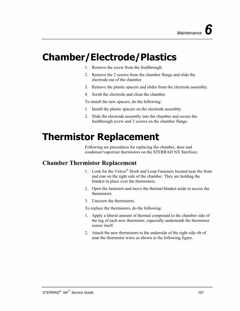
Maintenance 6
Chamber/Electrode/Plastics 1. Remove the screw from the feedthrough.
2. Remove the 2 screws from the chamber flange and slide the electrode out of the chamber.
3. Remove the plastic spacers and slides from the electrode assembly.
4. Scrub the electrode and clean the chamber.
To install the new spacers, do the following:
1. Install the plastic spacers on the electrode assembly.
2. Slide the electrode assembly into the chamber and secure the feedthrough screw and 2 screws on the chamber flange.
Thermistor Replacement Following are procedures for replacing the chamber, door and condenser/vaporizer thermistors on the STERRAD NX Sterilizer.
Chamber Thermistor Replacement 1. Look for the Velcro® Hook and Loop Fasteners located near the front
and rear on the right side of the chamber. They are holding the blanket in place over the thermistors.
2. Open the fasteners and move the thermal blanket aside to access the thermistors.
3. Unscrew the thermistors.
To replace the thermistors, do the following:
1. Apply a liberal amount of thermal compound to the chamber side of the lug of each new thermistor, especially underneath the thermistor sensor itself.
2. Attach the new thermistors to the underside of the right side rib of near the thermistor wires as shown in the following figure.
STERRAD® NX™ Service Guide 107

6 Maintenance
Figure 39. Thermistor replacement. The thermistor wires indicated the location of the thermistors.
3. Bundle any excess length of thermistor cable in a figure-8 pattern instead of in a circular loop and secure with a cable tie.
Door Thermistor Replacement 1. Remove the door cover as shown in the removal and replacement
section.
2. Unscrew the thermistors.
To install the new thermistors, do the following:
1. Apply a liberal amount of thermal compound to the lug of the thermistor especially underneath the thermistor sensor.
2. Install the new thermistors. See the following figure for the location.
Figure 40. Door assembly showing the thermistor locations.
108 STERRAD® NX™ Service Guide
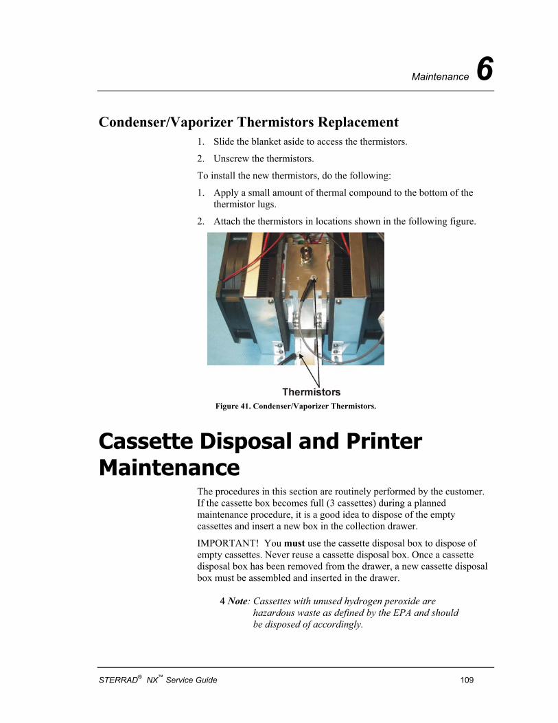
Maintenance 6
Condenser/Vaporizer Thermistors Replacement 1. Slide the blanket aside to access the thermistors.
2. Unscrew the thermistors.
To install the new thermistors, do the following:
1. Apply a small amount of thermal compound to the bottom of the thermistor lugs.
2. Attach the thermistors in locations shown in the following figure.
Figure 41. Condenser/Vaporizer Thermistors.
Cassette Disposal and Printer Maintenance
The procedures in this section are routinely performed by the customer. If the cassette box becomes full (3 cassettes) during a planned maintenance procedure, it is a good idea to dispose of the empty cassettes and insert a new box in the collection drawer.
IMPORTANT! You must use the cassette disposal box to dispose of empty cassettes. Never reuse a cassette disposal box. Once a cassette disposal box has been removed from the drawer, a new cassette disposal box must be assembled and inserted in the drawer.
4 Note: Cassettes with unused hydrogen peroxide are hazardous waste as defined by the EPA and should be disposed of accordingly.
STERRAD® NX™ Service Guide 109
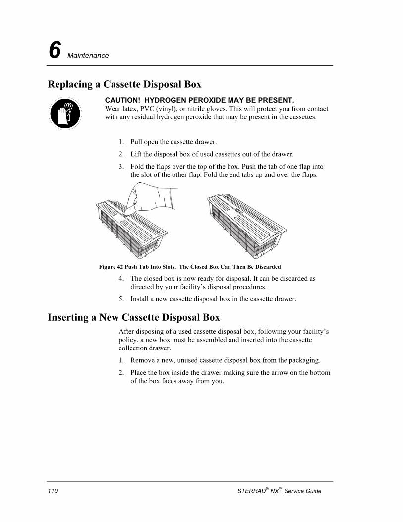
6 Maintenance
Replacing a Cassette Disposal Box
CAUTION! HYDROGEN PEROXIDE MAY BE PRESENT. Wear latex, PVC (vinyl), or nitrile gloves. This will protect you from contact with any residual hydrogen peroxide that may be present in the cassettes.
1. Pull open the cassette drawer.
2. Lift the disposal box of used cassettes out of the drawer.
3. Fold the flaps over the top of the box. Push the tab of one flap into the slot of the other flap. Fold the end tabs up and over the flaps.
Figure 42 Push Tab Into Slots. The Closed Box Can Then Be Discarded
4. The closed box is now ready for disposal. It can be discarded as directed by your facility’s disposal procedures.
5. Install a new cassette disposal box in the cassette drawer.
Inserting a New Cassette Disposal Box After disposing of a used cassette disposal box, following your facility’s policy, a new box must be assembled and inserted into the cassette collection drawer.
1. Remove a new, unused cassette disposal box from the packaging.
2. Place the box inside the drawer making sure the arrow on the bottom of the box faces away from you.
110 STERRAD® NX™ Service Guide
Maintenance 6
Figure 43. Correct Placement of Cassette Box in Drawer. Notice the Direction of the Arrow in the Box.
3. Tuck the flaps on the box inside the drawer edges. Close the drawer.
Cleaning the Thermal Printer Head Inspect the quality of the printed information at the planned maintenance interval. If the quality of the printed information is faint or has blank spots, the thermal printer head needs to be cleaned.
WARNING! THE PRINT MECHANISM MAY BE HOT IMMEDIATELY AFTER PRINTING. ALLOW IT TO COOL COMPLETELY BEFORE CLEANING.
Caution: Do not use abrasive materials or sharp objects to clean any printer mechanism.
To clean the thermal printer head, do the following:
1. Turn the release lever until the platen block separates from the printer mechanism. Lift up the platen block.
2. Clean the heating elements using isopropyl alcohol and a cotton swab. Make sure no fibers from the swab remain on the elements.
3. After the alcohol is completely dry, reinstall the platen block onto the printer mechanism.
4. Load the paper into the printer and close the printer door.
STERRAD® NX™ Service Guide 111
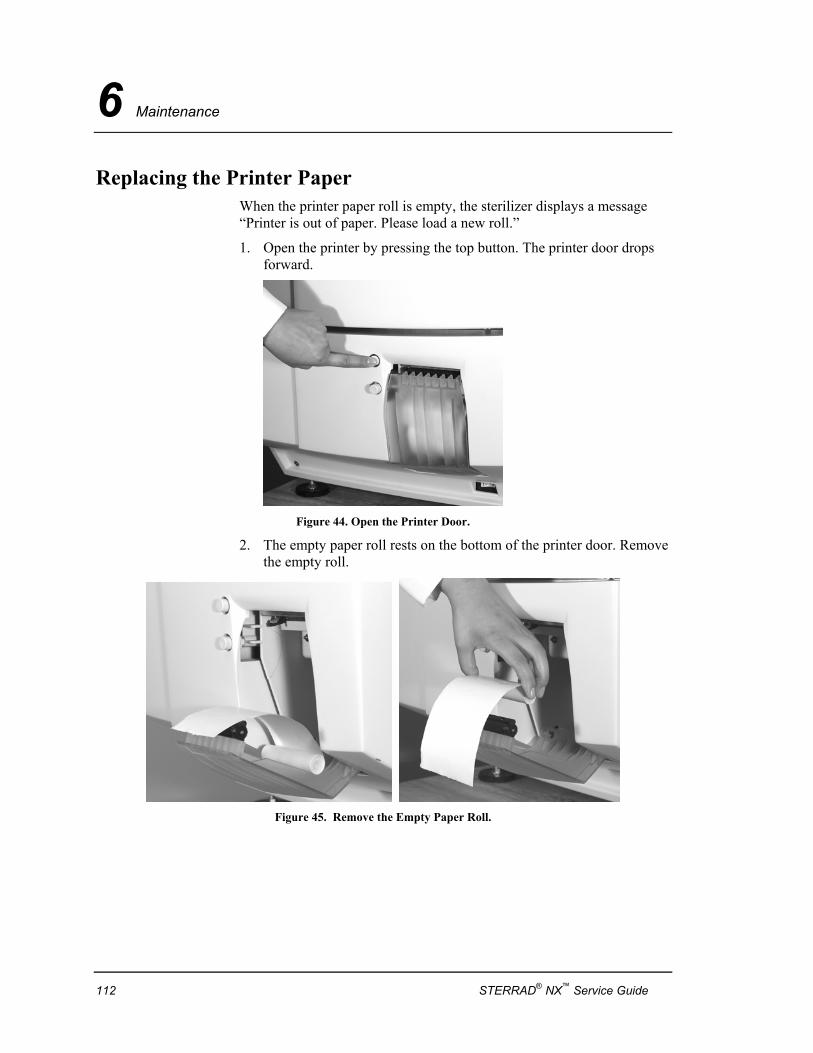
6 Maintenance
Replacing the Printer Paper When the printer paper roll is empty, the sterilizer displays a message “Printer is out of paper. Please load a new roll.”
1. Open the printer by pressing the top button. The printer door drops forward.
Figure 44. Open the Printer Door.
2. The empty paper roll rests on the bottom of the printer door. Remove the empty roll.
Figure 45. Remove the Empty Paper Roll.
112 STERRAD® NX™ Service Guide
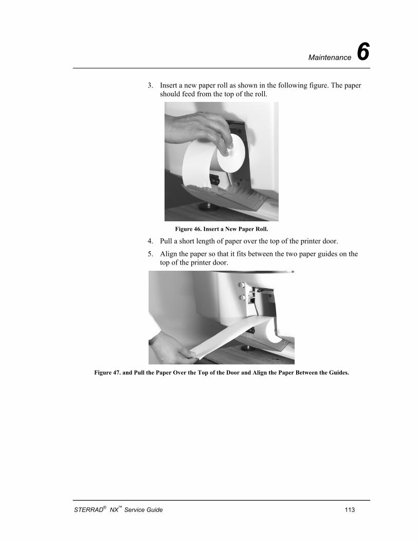
Maintenance 6
3. Insert a new paper roll as shown in the following figure. The paper should feed from the top of the roll.
Figure 46. Insert a New Paper Roll.
4. Pull a short length of paper over the top of the printer door.
5. Align the paper so that it fits between the two paper guides on the top of the printer door.
Figure 47. and Pull the Paper Over the Top of the Door and Align the Paper Between the Guides.
STERRAD® NX™ Service Guide 113
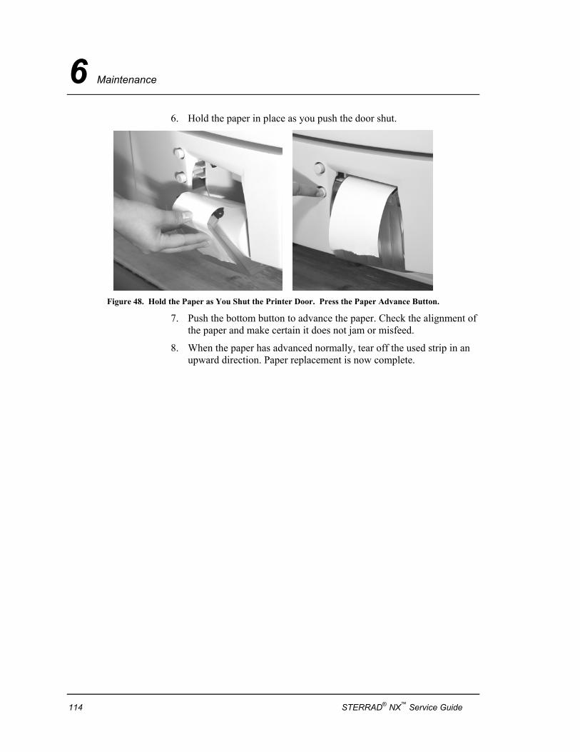
6 Maintenance
6. Hold the paper in place as you push the door shut.
Figure 48. Hold the Paper as You Shut the Printer Door. Press the Paper Advance Button.
7. Push the bottom button to advance the paper. Check the alignment of the paper and make certain it does not jam or misfeed.
8. When the paper has advanced normally, tear off the used strip in an upward direction. Paper replacement is now complete.
114 STERRAD® NX™ Service Guide
System Calibration and Verification 7
Chapter 7.
System Calibration and Verification
Overview The STERRAD® NX™ Sterilizer has onboard calibration tools to make it easy to calibrate the various components of the system. As of this publication, calibration is still being researched and the procedures presented here are subject to change. Please contact ASP Technical Service prior to performing any calibration procedure.
Service Action Table Use the system verification procedures to verify sterilizer performance whenever the service actions listed in the following table are completed.
Service Action Performed System Verification Test Requirements PM All tests.
All Service Vacuum plasma test, plasma power measurement, temperature verification, diagnostics other tests and run standard cycle.
Replace vacuum subsystem components
Vacuum plasma test, leak test, plasma power measurement, temperature verification, diagnostics other tests and run standard cycle.
Replace plasma subsystem components
Vacuum plasma test, leak test, plasma power measurement, temperature verification, diagnostics other tests and run standard cycle.
STERRAD® NX™ Service Guide 115
7 System Calibration and Verification
Service Action Performed System Verification Test Requirements Replace AC enclosure components Leak back test, plasma power measurement, door and
chamber temperature, door /chamber heater voltage, injector valve heater voltage.
Replace controller or components Reprogram customer details, cycle information, pm and login. Complete power supplies test and verification, temperature calibration, neutral density and standard and advanced cycle.
Replace thermistor Complete temperature verification and complete standard cycle.
Replace delivery system components Leak back test, cassette guide test and complete cycle.
Replace door lock or sensor Door operation and complete cycle.
Replace printer Complete printer test and perform complete cycle.
Zeroing Pressure Transducers 4 Note: Prior to conducting this procedure, ensure that
the sterilizer has been powered on, and the chamber and vaporizer assembly temperature are regulating at their respective setpoints. (50º C on the chamber and 70º C on the vaporizer.) Also, the system leak rate must be ≤ 25 mtorr per minute. Be sure you record the sterilizer serial number, all pressure transducers’ serial numbers, and the calibration instrumentation information on the calibration data sheet that is included with the calibration package.
1. Remove the pressure switch from the pressure control manifold.
2. Connect the KF16-7/16 thread adaptor to the pressure switch port.
3. Connect a calibrated vacuum gauge to the KF16 adaptor using the KF16 centering ring and clamp.
4. Navigate to the Additional Utilities/Service Functions/Calibration Tests/Pressure Calibration display. Press start to pump the system down.
5. Allow the chamber pressure to stabilize. This should be below 50 mTorr (microns) as indicated on the vacuum gauge.
116 STERRAD® NX™ Service Guide
System Calibration and Verification 7
6. Once the system has stabilized, adjust the zeroing potentiometers on the vaporizer and chamber pressure transducers so that their pressure indications match the pressure displayed on the calibrated vacuum gauge.
7. When completed, vent the system. Remove the vacuum gauge and adaptor and reinstall the pressure switch.
Leak Test If the leak test is being performed after a cycle has been run, navigate to the “heater” screen in service mode. Set the condenser temperature to 70° C. Navigate to the Vacuum/Plasma screen, then open the inlet valve and pump the system down to less than 100 mtorr for 20 minutes. After 20 minutes, vent to atmosphere (press Back). This removes residual moisture from the system that could impact the leak back test.
1. At the Vacuum/Plasma screen verify the following:
♦ The vacuum valve is closed.
♦ The vent valve is closed.
♦ The inlet valve is closed.
♦ The transition valve is closed.
♦ The oil return valve is closed.
♦ The system is at atmosphere.
2. Turn on the vacuum pump, then open only the vacuum, inlet, and transition valves.
3. Wait until the chamber pressure transducer reads less than 300 mtorr. The vaporizer pressure should give approximately the same reading as the chamber pressure.
To measure the leak back, do the following:
1. Close the vacuum valve and turn off the vacuum pump. Leave the inlet and transition valves open.
2. Simultaneously measure chamber pressure and start the timer or record start time including seconds. This is the initial pressure. Record on the test record sheet.
3. After a duration of at least 10 minutes, measure chamber pressure. This is the final pressure. Record final pressure and actual duration on the test record sheet.
STERRAD® NX™ Service Guide 117
7 System Calibration and Verification
4. Subtract the initial pressure from the final pressure. Divide this difference by the duration (at least 10 minutes) to obtain system leak-back rate in mtorr/min.
5. If this value is 25 mtorr/minute or less, the system passed. If not, troubleshoot cause and retest. Record result on the test record sheet.
6. Turn on the vacuum pump and open the vacuum valve. Turn off the pump and open the vent valve. This will allow the chamber and vacuum pump to come up to atmospheric pressure without sucking the oil out of the pump and into the chamber.
7. Exit the Vacuum/Plasma screen.
Plasma Power Delivery Verification This section describes the steps for verifying the output of the LFPS II against a traceable reference. This procedure requires the use of the LFPS II Power Verification Meter (PVM).
1. Turn OFF the sterilizer and disconnect the power cable.
2. Disconnect the twin-axial cable from the LFPS II PSM and connect this cable to the LFPS II PVM.
3. Connect one end of the 1-foot twin-axial cable to the LFPS II PSM. Connect the other end of the 1-foot twin-axial cable to the LFPS II PVM.
4. Connect the IEC 320 power cable to the PVM and turn the PVM on. Connect the BNC to dual banana adapter to the PVM. Connect the DVM to the PVM dual banana adapter.
5. Apply power to the sterilizer. Using the service log-in, run the plasma test at 800 mtorr.
6. Read the output voltage on the DVM. Output should be between 3.82 - 4.79 VDC. If the output is correct, the test is complete. If the output is not correct, troubleshoot the system and replace components if needed.
118 STERRAD® NX™ Service Guide
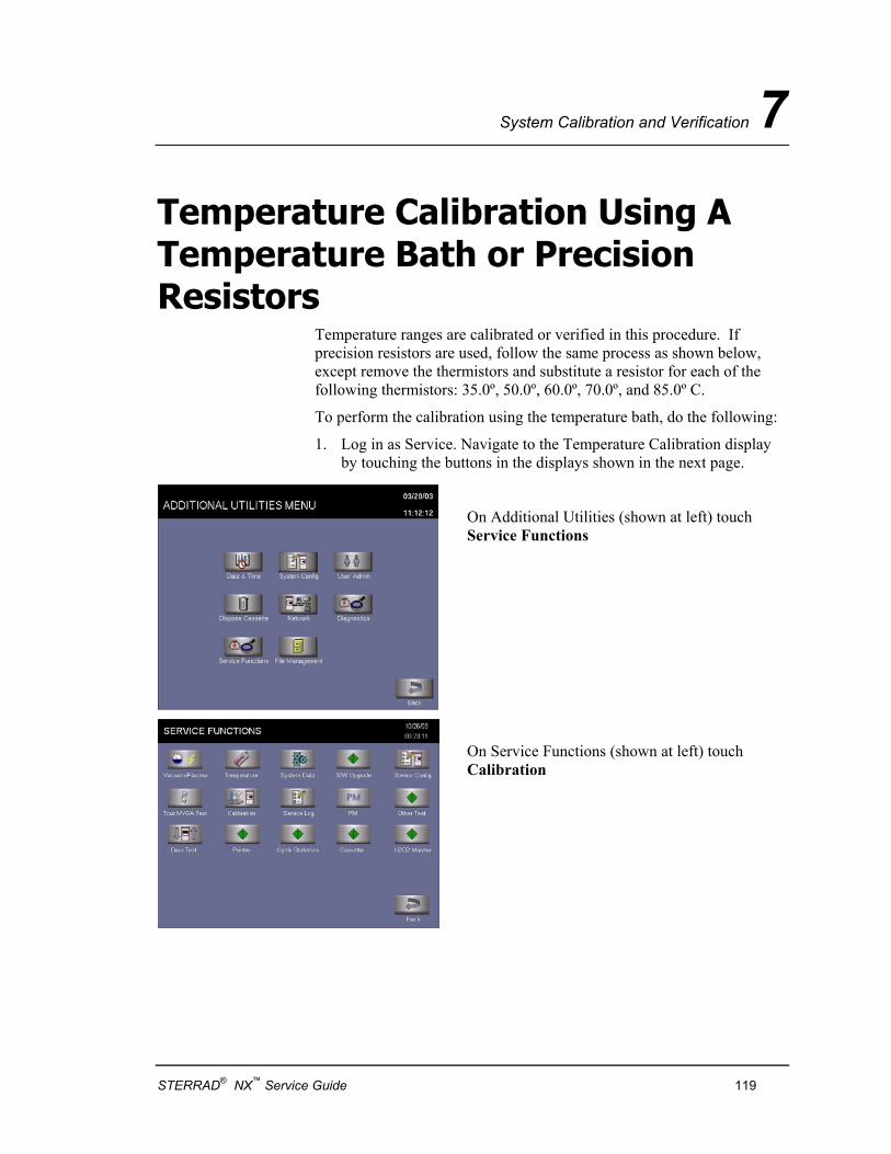
System Calibration and Verification 7
Temperature Calibration Using A Temperature Bath or Precision Resistors
Temperature ranges are calibrated or verified in this procedure. If precision resistors are used, follow the same process as shown below, except remove the thermistors and substitute a resistor for each of the following thermistors: 35.0º, 50.0º, 60.0º, 70.0º, and 85.0º C.
To perform the calibration using the temperature bath, do the following:
1. Log in as Service. Navigate to the Temperature Calibration display by touching the buttons in the displays shown in the next page.
On Additional Utilities (shown at left) touch Service Functions
On Service Functions (shown at left) touch Calibration
STERRAD® NX™ Service Guide 119
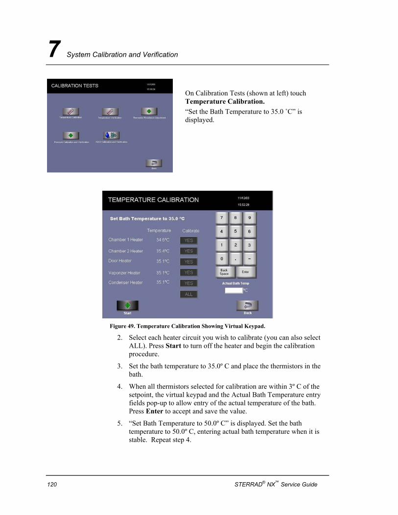
7 System Calibration and Verification
On Calibration Tests (shown at left) touch Temperature Calibration. “Set the Bath Temperature to 35.0 ˚C” is displayed.
Figure 49. Temperature Calibration Showing Virtual Keypad.
2. Select each heater circuit you wish to calibrate (you can also select ALL). Press Start to turn off the heater and begin the calibration procedure.
3. Set the bath temperature to 35.0º C and place the thermistors in the bath.
4. When all thermistors selected for calibration are within 3º C of the setpoint, the virtual keypad and the Actual Bath Temperature entry fields pop-up to allow entry of the actual temperature of the bath. Press Enter to accept and save the value.
5. “Set Bath Temperature to 50.0º C” is displayed. Set the bath temperature to 50.0º C, entering actual bath temperature when it is stable. Repeat step 4.
120 STERRAD® NX™ Service Guide
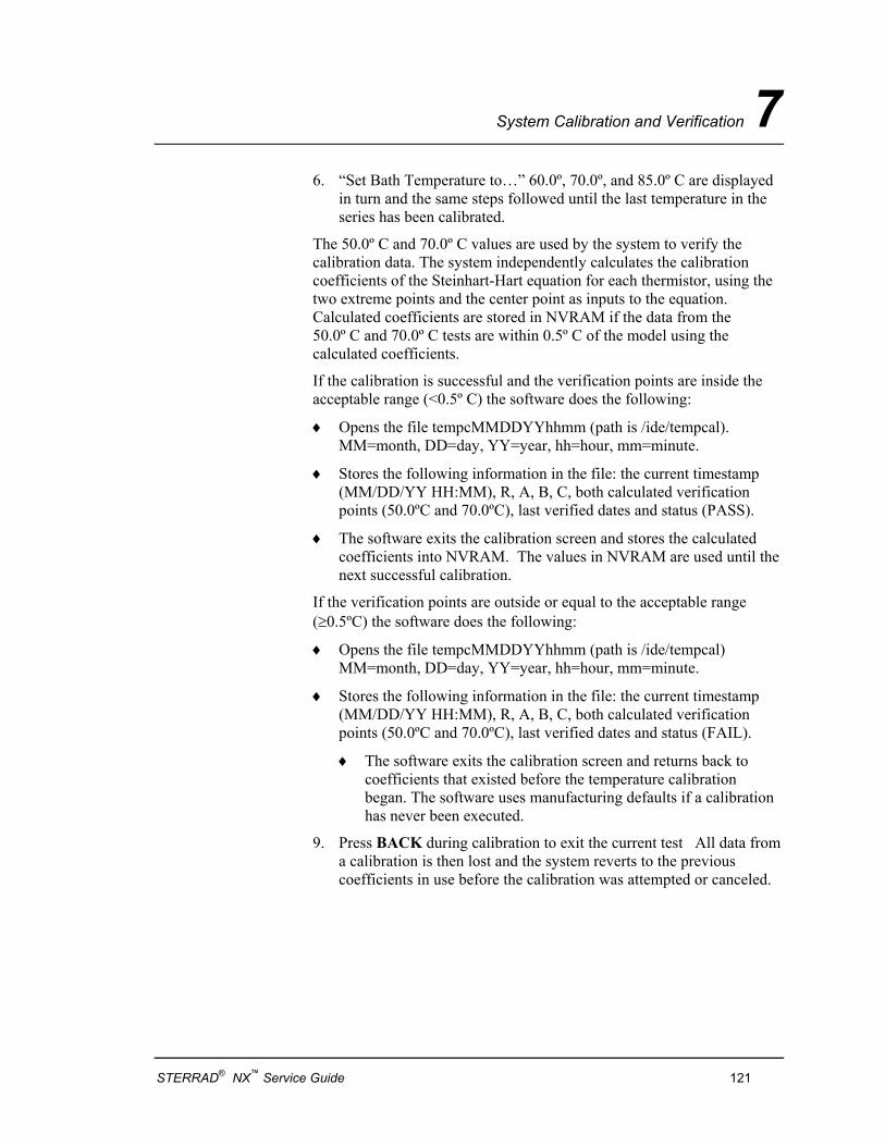
System Calibration and Verification 7
6. “Set Bath Temperature to…” 60.0º, 70.0º, and 85.0º C are displayed in turn and the same steps followed until the last temperature in the series has been calibrated.
The 50.0º C and 70.0º C values are used by the system to verify the calibration data. The system independently calculates the calibration coefficients of the Steinhart-Hart equation for each thermistor, using the two extreme points and the center point as inputs to the equation. Calculated coefficients are stored in NVRAM if the data from the 50.0º C and 70.0º C tests are within 0.5º C of the model using the calculated coefficients.
If the calibration is successful and the verification points are inside the acceptable range (<0.5º C) the software does the following:
♦ Opens the file tempcMMDDYYhhmm (path is /ide/tempcal). MM=month, DD=day, YY=year, hh=hour, mm=minute.
♦ Stores the following information in the file: the current timestamp (MM/DD/YY HH:MM), R, A, B, C, both calculated verification points (50.0ºC and 70.0ºC), last verified dates and status (PASS).
♦ The software exits the calibration screen and stores the calculated coefficients into NVRAM. The values in NVRAM are used until the next successful calibration.
If the verification points are outside or equal to the acceptable range (≥0.5ºC) the software does the following:
♦ Opens the file tempcMMDDYYhhmm (path is /ide/tempcal) MM=month, DD=day, YY=year, hh=hour, mm=minute.
♦ Stores the following information in the file: the current timestamp (MM/DD/YY HH:MM), R, A, B, C, both calculated verification points (50.0ºC and 70.0ºC), last verified dates and status (FAIL).
♦ The software exits the calibration screen and returns back to coefficients that existed before the temperature calibration began. The software uses manufacturing defaults if a calibration has never been executed.
9. Press BACK during calibration to exit the current test All data from a calibration is then lost and the system reverts to the previous coefficients in use before the calibration was attempted or canceled.
STERRAD® NX™ Service Guide 121
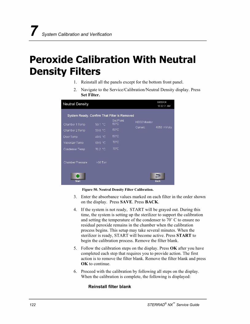
7 System Calibration and Verification
Peroxide Calibration With Neutral Density Filters
1. Reinstall all the panels except for the bottom front panel.
2. Navigate to the Service/Calibration/Neutral Density display. Press Set Filter.
Figure 50. Neutral Density Filter Calibration.
3. Enter the absorbance values marked on each filter in the order shown on the display. Press SAVE. Press BACK.
4. If the system is not ready, START will be grayed out. During this time, the system is setting up the sterilizer to support the calibration and setting the temperature of the condenser to 70˚ C to ensure no residual peroxide remains in the chamber when the calibration process begins. This setup may take several minutes. When the sterilizer is ready, START will become active. Press START to begin the calibration process. Remove the filter blank.
5. Follow the calibration steps on the display. Press OK after you have completed each step that requires you to provide action. The first action is to remove the filter blank. Remove the filter blank and press OK to continue.
6. Proceed with the calibration by following all steps on the display. When the calibration is complete, the following is displayed:
Reinstall filter blank
122 STERRAD® NX™ Service Guide
System Calibration and Verification 7
7. A calibration report is automatically printed upon successful completion of the calibration. Review the report, ensure it indicates “H2O2 Monitor: Passed” and tape the report to the Product Verification Form.
8. Power the system off for 30 seconds. Power on to reset the H2O2 detector reference voltage.
Diagnostics 1. Log in with SERVICE access and run the step-by-step diagnostics
(select OTHER diagnostic functions; do not select TEMPERATURE diagnostics).
Temperature Verification 1. Run an empty chamber Standard Cycle until it is completed.
2. Log in as “Service.” Navigate to the Service/Temperature display.
3. Using an electronic thermometer, measure the temperature at the chamber 1, door, vaporizer, and condenser thermistors. Record the system display and electronic thermometer readings on the Product Verification Form.
STERRAD® NX™ Service Guide 123

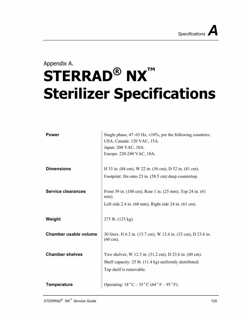
Specifications A
Appendix A.
STERRAD® NX™ Sterilizer Specifications
Power Single phase, 47–63 Hz, ±10%, per the following countries: USA, Canada: 120 VAC, 15A. Japan: 200 VAC, 10A. Europe: 220-240 VAC, 10A.
Dimensions H 33 in. (84 cm), W 22 in. (56 cm), D 32 in. (81 cm).
Footprint: fits onto 23 in. (58.5 cm) deep countertop.
Service clearances Front 39 in. (100 cm), Rear 1 in. (25 mm), Top 24 in. (61 mm).
Left side 2.4 in. (60 mm), Right side 24 in. (61 cm).
Weight 275 lb. (125 kg).
Chamber usable volume 30 liters. H 6.2 in. (15.7 cm), W 12.6 in. (32 cm), D 23.6 in. (60 cm).
Chamber shelves Two shelves, W 12.3 in. (31.2 cm), D 23.6 in. (60 cm).
Shelf capacity: 25 lb. (11.4 kg) uniformly distributed.
Top shelf is removable.
Temperature Operating: 18 o C – 35 o C (64 o F – 95 o F).
STERRAD® NX™ Service Guide 125
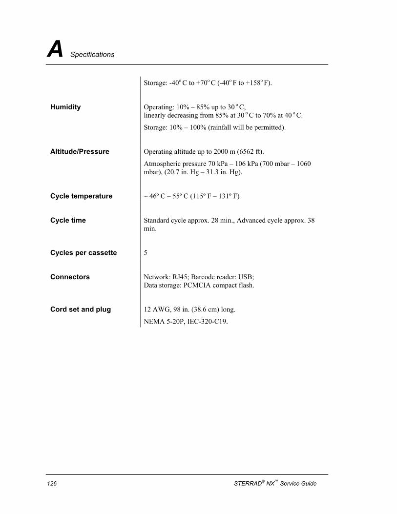
A Specifications
Storage: -40o C to +70o C (-40o F to +158o F).
Humidity Operating: 10% – 85% up to 30 o C, linearly decreasing from 85% at 30 o C to 70% at 40 o C.
Storage: 10% – 100% (rainfall will be permitted).
Altitude/Pressure Operating altitude up to 2000 m (6562 ft).
Atmospheric pressure 70 kPa – 106 kPa (700 mbar – 1060 mbar), (20.7 in. Hg – 31.3 in. Hg).
Cycle temperature ~ 46º C – 55º C (115º F – 131º F)
Cycle time Standard cycle approx. 28 min., Advanced cycle approx. 38 min.
Cycles per cassette 5
Connectors Network: RJ45; Barcode reader: USB; Data storage: PCMCIA compact flash.
Cord set and plug 12 AWG, 98 in. (38.6 cm) long.
NEMA 5-20P, IEC-320-C19.
126 STERRAD® NX™ Service Guide


