Steve Lidia ICFA Workshop, Chia Laguna July, 2002 Flat Beam Photoinjectors for Ultrafast Synchrotron Radiation Sources Steve Lidia Lawrence Berkeley National Laboratory (and a host of others) WG1, ICFA Workshop, Chia Laguna
Transcript
Steve Lidia ICFA Workshop, Chia Laguna July, 2002
Flat Beam Photoinjectors for Ultrafast Synchrotron
Radiation Sources
Steve Lidia
Lawrence Berkeley National Laboratory
(and a host of others)
WG1, ICFA Workshop, Chia Laguna
Steve Lidia ICFA Workshop, Chia Laguna July, 2002
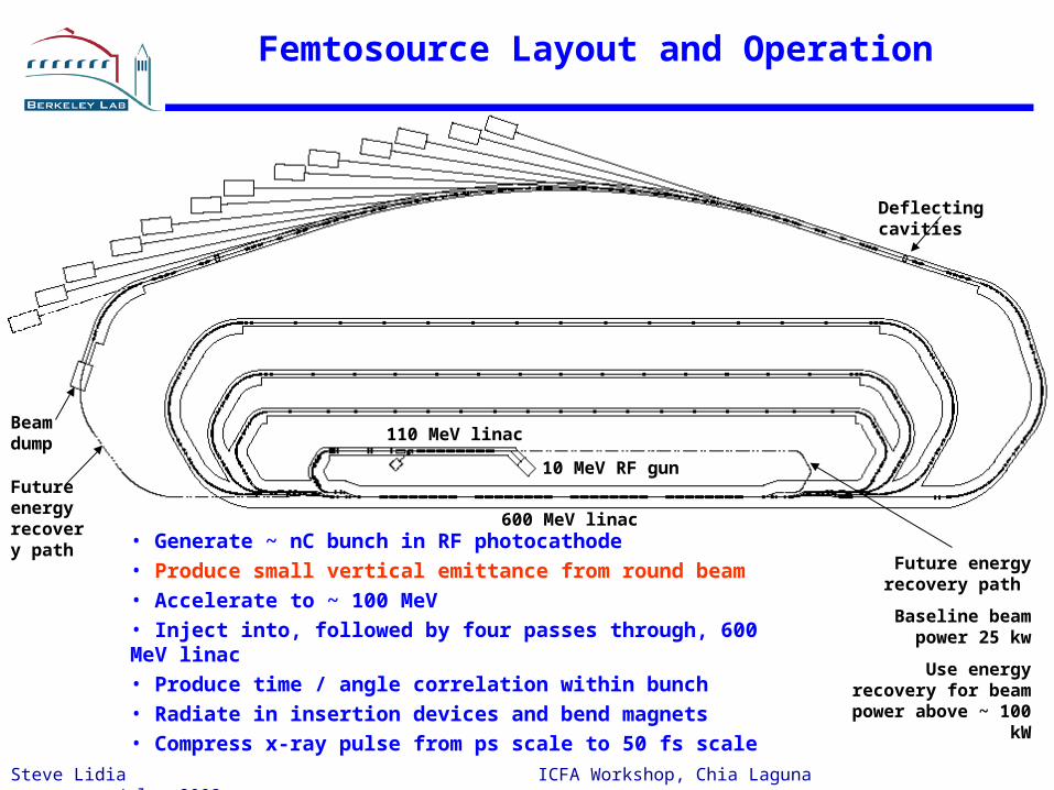
• Generate ~ nC bunch in RF photocathode• Produce small vertical emittance from round beam• Accelerate to ~ 100 MeV• Inject into, followed by four passes through, 600 MeV linac• Produce time / angle correlation within bunch• Radiate in insertion devices and bend magnets• Compress x-ray pulse from ps scale to 50 fs scale
Femtosource Layout and Operation
Beam dumpFuture energy recovery path
10 MeV RF gun
110 MeV linac
600 MeV linac
Future energy recovery path
Baseline beam power 25 kw
Use energy recovery for beam
power above ~ 100 kW
Deflecting cavities
Steve Lidia ICFA Workshop, Chia Laguna July, 2002
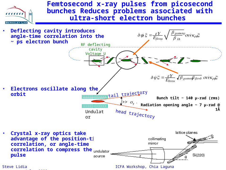
Femtosecond x-ray pulses from picosecond bunches Reduces problems associated with
ultra-short electron bunches
• Deflecting cavity introduces angle-time correlation into the ~ ps electron bunch
• Electrons oscillate along the orbit
• Crystal x-ray optics take advantage of the position-time correlation, or angle-time correlation to compress the pulse
tail trajectory
Undulator
>> r ’
head trajectory
RF deflecting cavityVoltage U
δy' z = eU
Ebeam
β cavity
β IDsinkrfz
δy z = eUEbeam
β cavityβ bendsinkrfz
Bunch tilt ~ 140 µ-rad (rms)
Radiation opening angle ~ 7 µ-rad @ 1Å
Steve Lidia ICFA Workshop, Chia Laguna July, 2002
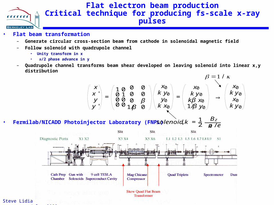
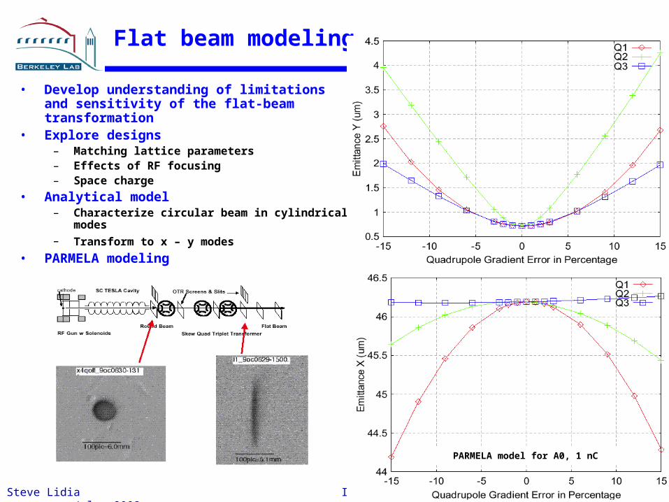
Flat electron beam productionCritical technique for producing fs-scale x-ray pulses
• Flat beam transformation– Generate circular cross-section beam from cathode in solenoidal magnetic field– Follow solenoid with quadrupole channel
• Unity transform in x• /2 phase advance in y
– Quadrupole channel transforms beam shear developed on leaving solenoid into linear x,y distribution
• Fermilab/NICADD Photoinjector Laboratory (FNPL) solenoid, k = 12
Bz
p0 / e
β =1 / k
xx 'y
y '
=1 00 10 00 0
0 00 00 β
1/β 0
x0k y0y0
k x0
=
x0
k y0
kβ x01/β y0
⇒
x0k y0x0
k y0
Steve Lidia ICFA Workshop, Chia Laguna July, 2002
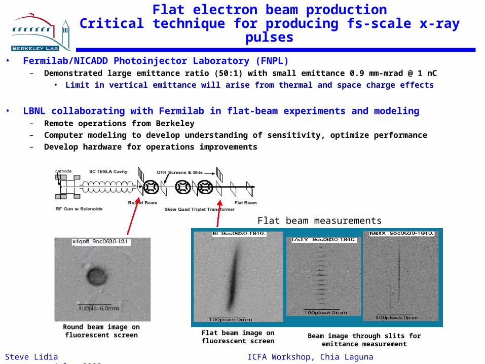
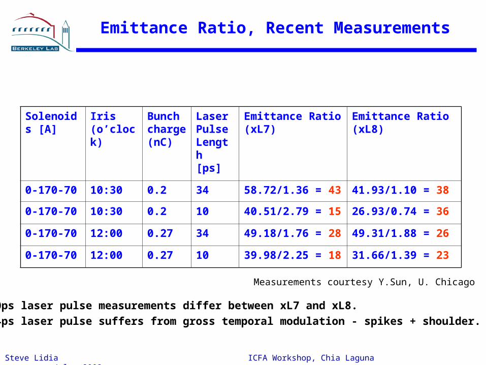
Flat beam measurements
Flat beam image on fluorescent screen
Beam image through slits for emittance measurement
Round beam image on fluorescent screen
Flat electron beam productionCritical technique for producing fs-scale x-ray pulses
• Fermilab/NICADD Photoinjector Laboratory (FNPL)– Demonstrated large emittance ratio (50:1) with small emittance 0.9 mm-mrad @ 1 nC
• Limit in vertical emittance will arise from thermal and space charge effects
• LBNL collaborating with Fermilab in flat-beam experiments and modeling – Remote operations from Berkeley– Computer modeling to develop understanding of sensitivity, optimize performance– Develop hardware for operations improvements
Steve Lidia ICFA Workshop, Chia Laguna July, 2002
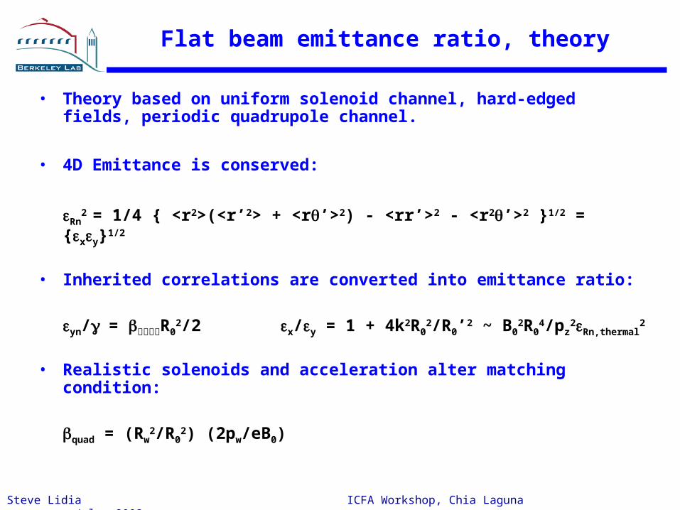
Emittance Compensation in Angular Momentum Dominated Beams
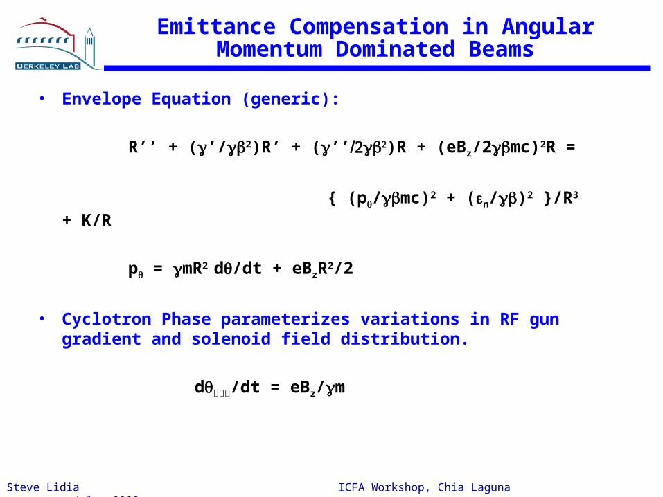
• Envelope Equation (generic):
R’’ + (’/β2)R’ + (’’β)R + (eBz/2βmc)2R =
{ (p/βmc)2 + (n/β)2 }/R3 + K/R
p = mR2 d/dt + eBzR2/2
• Cyclotron Phase parameterizes variations in RF gun gradient and solenoid field distribution.
d/dt = eBz/m
Steve Lidia ICFA Workshop, Chia Laguna July, 2002
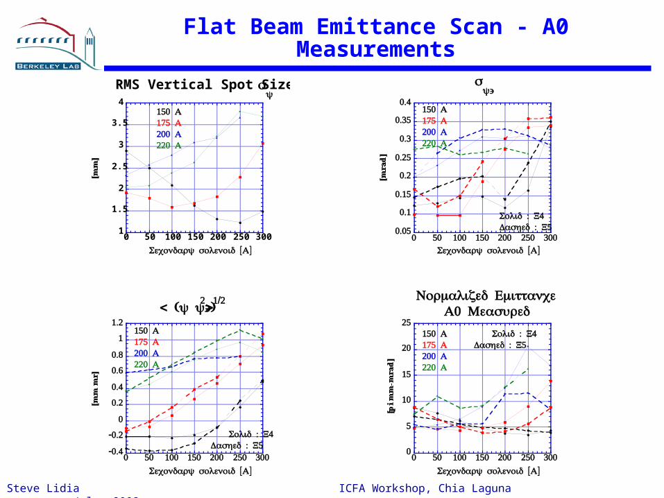
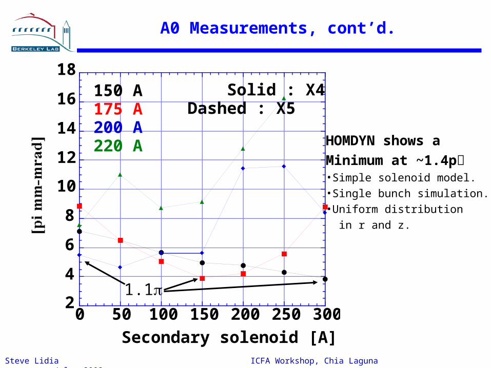
Emittance compensation studies at A0
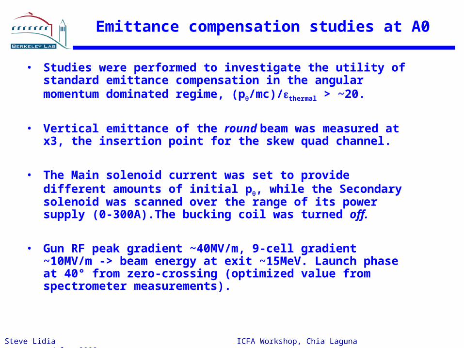
• Studies were performed to investigate the utility of standard emittance compensation in the angular momentum dominated regime, (p/mc)/thermal > ~20.
• Vertical emittance of the round beam was measured at x3, the insertion point for the skew quad channel.
• The Main solenoid current was set to provide different amounts of initial p, while the Secondary solenoid was scanned over the range of its power supply (0-300A).The bucking coil was turned off.
• Gun RF peak gradient ~40MV/m, 9-cell gradient ~10MV/m -> beam energy at exit ~15MeV. Launch phase at 40° from zero-crossing (optimized value from spectrometer measurements).
Steve Lidia ICFA Workshop, Chia Laguna July, 2002
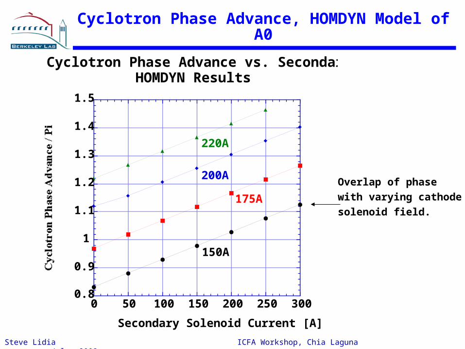
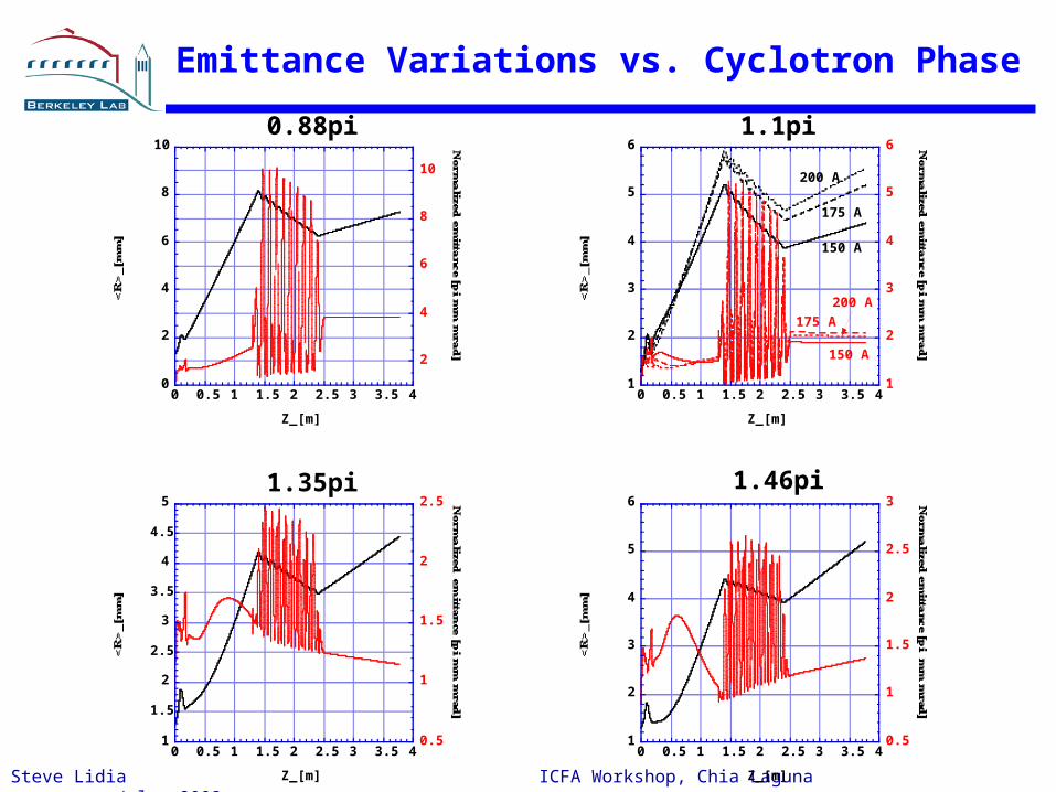
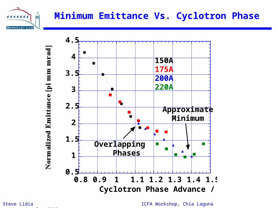
Cyclotron Phase Advance, HOMDYN Model of A0
0.8
0.9
1
1.1
1.2
1.3
1.4
1.5
0 50 100 150 200 250 300
Cyclotron Phase Advance vs. Secondary SolenoidHOMDYN Results
Secondary Solenoid Current [A]
150A
175A
200A
220A
Overlap of phase with varying cathodesolenoid field.