19
06/12/2018 – STFER_WB Version 1.5.0 – Manual R001-EN STFER FOR ANSYS WORKBENCH Theory Manual

06/12/2018 – STFER_WB Version 1.5.0 – Manual R001-EN
STFER FOR ANSYS WORKBENCH
Theory Manual
STFER for Ansys Workbench – Theory Manual
Ref : STFER_WB 1.5.0 – Manual R001-EN 06/12/2018
Auteurs : E. Monroig Page 2 sur 19
CONTENTS
1. Object.......................................................................................................... 3
2. History of changes ..................................................................................... 3
3. Processing of combined results ................................................................. 4
3.1. Vocabulary ........................................................................................... 4
3.2. Systematic calculation ......................................................................... 4
3.3. MinMax Envelope ................................................................................ 4
4. Longitudinal reinforcements ..................................................................... 5
4.1. Plate and shell elements...................................................................... 5
4.1.1. Introduction ................................................................................... 5
4.1.2. Definitions and conventions.......................................................... 5
4.1.3. Elements with linear stress profile .............................................. 6
4.1.4. Extracting finite element results .................................................. 7
4.1.5. Longitudinal reinforcements: analytical method ......................... 7
4.1.6. Longitudinal reinforcements: analytical method with envelope
polygon ..................................................................................................... 10
4.2. Equilibrium of a reinforced concrete rectangular section ................ 11
4.2.1. Introduction ................................................................................. 11
4.2.2. Definitions and conventions........................................................ 11
4.2.3. Equilibrium equations ................................................................ 12
4.2.4. Available behavior laws .............................................................. 13
5. Transverse reinforcements ...................................................................... 15
5.1. Maximum transverse shear force ...................................................... 15
5.2. Eurocode 2 .......................................................................................... 15
5.2.1. Notations ..................................................................................... 15
5.2.2. Resistance of concrete alone ....................................................... 15
5.2.3. Resistance with transverse reinforcements ............................... 16
5.2.4. Shear combined with tension ...................................................... 17
5.2.5. Results ......................................................................................... 18
6. Bibliography ............................................................................................. 19
STFER for Ansys Workbench – Theory Manual
Ref : STFER_WB 1.5.0 – Manual R001-EN 06/12/2018
Auteurs : E. Monroig Page 3 sur 19
1. OBJECT
STFER for Ansys Workbench is a software for post-processing finite element results
to compute reinforcement ratios of concrete structures (such as slabs, walls, …) that
are modelled with shell or plate elements:
1. define combinations of load cases,
2. combine internal forces using these combinations,
3. compute reinforcement ratios.
This manual describes the methods used by STFER for Ansys Workbench version
1.5.0, which is used in the extension “Reinforcement Design V1.0”.
For guidance on how to use the software, refer to the User Manual [1].
For more information on this manual ask [email protected].
2. HISTORY OF CHANGES
– Version 1.5.0: First public version.
STFER for Ansys Workbench – Theory Manual
Ref : STFER_WB 1.5.0 – Manual R001-EN 06/12/2018
Auteurs : E. Monroig Page 4 sur 19
3. PROCESSING OF COMBINED RESULTS
This chapter describes specific processing that may be done on finite element results
before they are passed on the reinforcement computation algorithms.
3.1. VOCABULARY
Load cases can be either one step of the finite element calculation, or a list of steps.
Groups are logical groups of load cases or of other groups, with coefficients. The load
cases can be summed (‘+’ operation), or can be mutually exclusive (‘OR’ operation),
etc.
Combinations are defined in terms of load cases or groups and appropriate
coefficients.
All of these are defined by the user (for details refer to the User Manual [1]).
From the combinations, STFER defines elementary combinations by considering all
possibilities. Thus, depending on how the user defined the combinations, a single
combination is often expanded into hundreds or thousands of elementary
combinations.
3.2. SYSTEMATIC CALCULATION
This is a default method.
For each shell or plate element, the reinforcement computation algorithm is applied
successively on all elementary combinations, and then the maximum reinforcement
areas are computed.
3.3. MINMAX ENVELOPE
This method will be added in a future version to provide performance enhancements.
STFER for Ansys Workbench – Theory Manual
Ref : STFER_WB 1.5.0 – Manual R001-EN 06/12/2018
Auteurs : E. Monroig Page 5 sur 19
4. LONGITUDINAL REINFORCEMENTS
4.1. PLATE AND SHELL ELEMENTS
4.1.1. Introduction
This chapter describes methods for the computation of steel reinforcements in plate
and shell elements.
4.1.2. Definitions and conventions
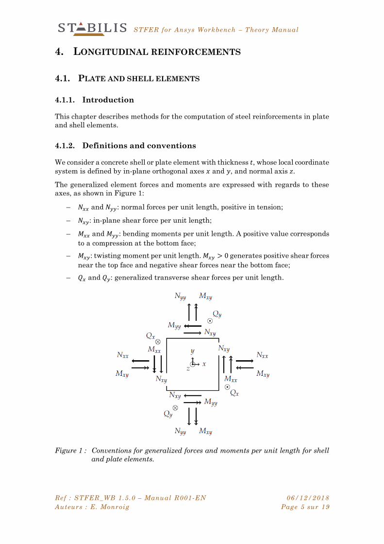
We consider a concrete shell or plate element with thickness 𝑡, whose local coordinate
system is defined by in-plane orthogonal axes 𝑥 and 𝑦, and normal axis 𝑧.
The generalized element forces and moments are expressed with regards to these
axes, as shown in Figure 1:
– 𝑁𝑥𝑥 and 𝑁𝑦𝑦: normal forces per unit length, positive in tension;
– 𝑁𝑥𝑦: in-plane shear force per unit length;
– 𝑀𝑥𝑥 and 𝑀𝑦𝑦: bending moments per unit length. A positive value corresponds
to a compression at the bottom face;
– 𝑀𝑥𝑦: twisting moment per unit length. 𝑀𝑥𝑦 > 0 generates positive shear forces
near the top face and negative shear forces near the bottom face;
– 𝑄𝑥 and 𝑄𝑦: generalized transverse shear forces per unit length.
Figure 1 : Conventions for generalized forces and moments per unit length for shell
and plate elements.

STFER for Ansys Workbench – Theory Manual
Ref : STFER_WB 1.5.0 – Manual R001-EN 06/12/2018
Auteurs : E. Monroig Page 6 sur 19
Generalized forces and moments are related to stress components by integration
over the thickness of the shell:
𝑁𝑥𝑥 = ∫ 𝜎𝑥𝑥 ⋅ ⅆ𝑧
𝑡 2⁄
−𝑡/2
, 𝑀𝑥𝑥 = ∫ 𝑧 ⋅ 𝜎𝑥𝑥 ⋅ ⅆ𝑧
𝑡 2⁄
−𝑡/2
, (1)
𝑁𝑦𝑦 = ∫ 𝜎𝑦𝑦 ⋅ ⅆ𝑧
𝑡 2⁄
−𝑡/2
, 𝑀𝑦𝑦 = ∫ 𝑧 ⋅ 𝜎𝑦𝑦 ⋅ ⅆ𝑧
𝑡 2⁄
−𝑡/2
, (2)
𝑁𝑥𝑦 = ∫ 𝜎𝑥𝑦 ⋅ ⅆ𝑧
𝑡 2⁄
−𝑡/2
, 𝑀𝑥𝑦 = ∫ 𝑧 ⋅ 𝜎𝑥𝑦 ⋅ ⅆ𝑧
𝑡 2⁄
−𝑡/2
, (3)
𝑄𝑥 = ∫ 𝜎𝑥𝑧 ⋅ ⅆ𝑧
𝑡 2⁄
−𝑡/2
, 𝑄𝑦 = ∫ 𝜎𝑦𝑧 ⋅ ⅆ𝑧
𝑡 2⁄
−𝑡/2
. (4)
The subscript 𝑡 (resp. 𝑏) is used for variables related to the top (resp. bottom) face.
4.1.3. Elements with linear stress profile
When the finite element model uses linear elements, the stress depends linearly on
the position along the thickness of the shell (Figure 2). For example, the 𝑥-axis stress
is given by:
𝜎𝑥𝑥(𝑧) =
𝜎𝑥𝑥𝑡𝑜𝑝
+ 𝜎𝑥𝑥𝑏𝑜𝑡
2+
𝑧
𝑡(𝜎𝑥𝑥
𝑡𝑜𝑝− 𝜎𝑥𝑥
𝑏𝑜𝑡). (5)
The generalized forces and moments become:
𝑁𝑥𝑥 =𝑡
2(𝜎𝑥𝑥
𝑡𝑜𝑝+ 𝜎𝑥𝑥
𝑏𝑜𝑡), 𝑀𝑥𝑥 =𝑡2
12(𝜎𝑥𝑥
𝑡𝑜𝑝 − 𝜎𝑥𝑥𝑏𝑜𝑡), (6)
𝑁𝑦𝑦 =𝑡
2(𝜎𝑦𝑦
𝑡𝑜𝑝 + 𝜎𝑦𝑦𝑏𝑜𝑡), 𝑀𝑦𝑦 =
𝑡2
12(𝜎𝑦𝑦
𝑡𝑜𝑝 − 𝜎𝑦𝑦𝑏𝑜𝑡), (7)
𝑁𝑥𝑦 =𝑡
2(𝜎𝑥𝑦
𝑡𝑜𝑝 + 𝜎𝑥𝑦𝑏𝑜𝑡), 𝑀𝑥𝑦 =
𝑡2
12(𝜎𝑥𝑦
𝑡𝑜𝑝 − 𝜎𝑥𝑦𝑏𝑜𝑡), (8)
𝑄𝑥 =𝑡
2(𝜎𝑥𝑧
𝑡𝑜𝑝 + 𝜎𝑥𝑧𝑏𝑜𝑡), 𝑄𝑦 =
𝑡
2(𝜎𝑦𝑧
𝑡𝑜𝑝 + 𝜎𝑦𝑧𝑏𝑜𝑡). (9)
Figure 2 : 𝑥-axis membrane stress 𝜎𝑥𝑥 with linear profile along the thickness of the
shell element.

STFER for Ansys Workbench – Theory Manual
Ref : STFER_WB 1.5.0 – Manual R001-EN 06/12/2018
Auteurs : E. Monroig Page 7 sur 19
4.1.4. Extracting finite element results
STFER uses generalized element forces and moments, extracted from the results of
the finite element calculation. They are computed as the mean of the results at Gauss
points.
If the generalized internal element forces are not available, they can be computed
from top and bottom stresses with equations (6) to (9), assuming a linear stress
profile.
4.1.5. Longitudinal reinforcements: analytical method
This method is activated by choosing “Analytical method” in the analysis settings
(see User Manual [1]). The user can choose the increment in angle 𝜃 (default value
is 5°, meaning that the following angles are taken into account: 0°, 5°, 10°, …, 355°).
4.1.5.1. Original method
This analytical method was developed by [4] and is sometimes referred to as the
‘Capra-Maury method’ or the facet rotation method.
The principle is to verify the equilibrium of a cross-section (so-called “facet”)
perpendicular to the element, and whose normal has an angle 𝜃 with the local 𝑥-axis
(Figure 3), with 𝜃 varying from 0 to 2𝜋. Equilibrium for all the facets implies
equilibrium of the shell or plate element.
The external forces are a normal force 𝑁𝜃 and a bending moment 𝑀𝜃. The resisting
forces are the concrete compression stress, and the forces 𝐹𝑏(𝜃) et 𝐹𝑡(𝜃) in the bottom
and top reinforcements; the methodology to determine the necessary resisting forces
is given in chapter 4.2.
𝐹𝑏(𝜃) ≤ 𝑅𝑏(𝜃) et 𝐹𝑡(𝜃) ≤ 𝑅𝑡(𝜃). (10)
The normal force and bending moment are obtained by rotating the tensor of
generalized forces and moments:
𝑁𝜃 = 𝑁𝑥𝑥cos2𝜃 + 𝑁𝑦𝑦sin2𝜃 + 2𝑁𝑥𝑦 cos 𝜃 sin 𝜃, (11)
𝑀𝜃 = 𝑀𝑥𝑥cos2𝜃 + 𝑀𝑦𝑦sin2𝜃 + 2𝑀𝑥𝑦 cos 𝜃 sin 𝜃. (12)
Similarly, the resisting forces of reinforcements placed respectively along the 𝑥-axis
and along the 𝑦-axis are obtained by:
𝐴𝑋𝜎𝑥cos2𝜃, (13)
𝐴𝑌𝜎𝑦sin2𝜃, (14)
where 𝐴𝑋 and 𝐴𝑌 are the reinforcement areas per unit length, and 𝜎𝑥 and 𝜎𝑦 are the
stresses in the reinforcements.
Thus, the total resisting force of the bottom or top reinforcements is equal to
𝑅(𝜃) = 𝐴𝑋𝜎𝑥cos2𝜃 + 𝐴𝑌𝜎𝑦sin2𝜃. (15)

STFER for Ansys Workbench – Theory Manual
Ref : STFER_WB 1.5.0 – Manual R001-EN 06/12/2018
Auteurs : E. Monroig Page 8 sur 19
Figure 3 : Cross section (so-called “facet”) with angle 𝜃 to the local 𝑥-axis.
Figure 4 : Validity domain considering all angles 𝜃.
Equation (15) is valid for either the bottom or top reinforcements, with resisting force
𝑅𝑏(𝜃)) or 𝑅𝑡(𝜃). The equilibrium condition for the bottom or top reinforcements thus
reads
𝐴𝑋𝜎𝑥cos2(𝜃) + 𝐴𝑌𝜎𝑦sin2(𝜃) ≥ 𝐹(𝜃). (16)
Each inequation for an angle 𝜃 defines a straight line in the plane (𝐴𝑋 , 𝐴𝑌). All the
lines taken together define the validity domain in which 𝐴𝑋 and 𝐴𝑌 can be chosen
(Figure 4). We note that the reinforcement stresses, 𝜎𝑥 and 𝜎𝑦, can vary with the
angle 𝜃.
The optimal solution is found by minimizing the total reinforcement area per unit
length, 𝐴𝑋 + 𝐴𝑌, with the constraints given by Equation (16), and 𝐴𝑋 ≥ 0 and 𝐴𝑌 ≥ 0.

STFER for Ansys Workbench – Theory Manual
Ref : STFER_WB 1.5.0 – Manual R001-EN 06/12/2018
Auteurs : E. Monroig Page 9 sur 19
4.1.5.2. Generalizations
Reinforcement angles
In the general case, the 𝑥-axis (resp. 𝑦-axis) reinforcement layer is not parallel to the
local 𝑥 (resp. 𝑦) axis but has an angle 𝛼 (resp. 𝛽) with it, see Figure 5.
Equation (15) is generalized as
𝑅(𝜃) = 𝐴𝑋𝜎𝑥cos2(𝜃 − 𝛼) + 𝐴𝑌𝜎𝑦sin2(𝜃 − 𝛽), (17)
and Equation (16) becomes
𝐴𝑋𝜎𝑥cos2(𝜃 − 𝛼) + 𝐴𝑌𝜎𝑦sin2(𝜃 − 𝛽) ≥ 𝐹(𝜃). (18)
Reinforcement positions in cross section
The original algorithm assumes that both the 𝑥-axis and 𝑦-axis reinforcements are
at the same position in the cross-section. The general case is handled in the following
way.
We note 𝑐𝑥 (resp. 𝑐𝑦) the distance between concrete surface and reinforcement
barycenter for the 𝑥-axis (resp. 𝑦-axis) reinforcements. For a given angle 𝜃, these
reinforcements are equivalent to a single reinforcement layer at position 𝑐𝜃, provided
that the global lever arm is unchanged:
𝑅(𝜃) ⋅ 𝑐𝜃 = (𝐴𝑋𝜎𝑥cos2(𝜃 − 𝛼)) ⋅ 𝑐𝑥 + (𝐴𝑌𝜎𝑦sin2(𝜃 − 𝛽)) ⋅ 𝑐𝑦 , (19)
or equivalently
𝑐𝜃 =
(𝐴𝑋𝜎𝑥cos2(𝜃 − 𝛼)) ⋅ 𝑐𝑥 + (𝐴𝑌𝜎𝑦sin2(𝜃 − 𝛽)) ⋅ 𝑐𝑦
𝐴𝑋𝜎𝑥cos2(𝜃 − 𝛼) + 𝐴𝑌𝜎𝑦sin2(𝜃 − 𝛽).
(20)
The value depends on reinforcement areas per unit length 𝐴𝑋 and 𝐴𝑌, distances 𝑐𝑥
and 𝑐𝑦, and stresses 𝜎𝑥 and 𝜎𝑦.
For the practical implementation, 𝑐𝜃 is computed by assuming 𝐴𝑋 = 𝐴𝑌, and by
assuming that 𝜎𝑥 (resp. 𝜎𝑦) is the maximum allowable value 𝜎𝑎,𝑥 (resp. 𝜎𝑎,𝑦).
Different steel parameters in 𝒙 and 𝒚 directions
Steel allowable stress may be different for the 𝑥-axis and 𝑦-axis reinforcements. In
this case the allowable stress of the equivalent reinforcement is given by
𝜎𝑎,𝜃 = 𝜎𝑎,𝑥cos2(𝜃 − 𝛼) + 𝜎𝑎,𝑦sin2(𝜃 − 𝛽). (21)
Figure 5 : Reinforcements positioned with an angle to the local axes.

STFER for Ansys Workbench – Theory Manual
Ref : STFER_WB 1.5.0 – Manual R001-EN 06/12/2018
Auteurs : E. Monroig Page 10 sur 19
4.1.6. Longitudinal reinforcements: analytical method with
envelope polygon
This method will be added in a future version to provide performance enhancements.
STFER for Ansys Workbench – Theory Manual
Ref : STFER_WB 1.5.0 – Manual R001-EN 06/12/2018
Auteurs : E. Monroig Page 11 sur 19
4.2. EQUILIBRIUM OF A REINFORCED CONCRETE RECTANGULAR
SECTION
4.2.1. Introduction
This chapter describes the methodology to justify the resistance of a rectangular
reinforced concrete section to a normal force 𝑁 and a bending moment 𝑀.
It is used for the automatic computation of steel reinforcements in shell elements,
with the method described in chapter 4.1.5 or 4.1.6.
For clarity we show here the case of positive bending moment (𝑀 > 0).
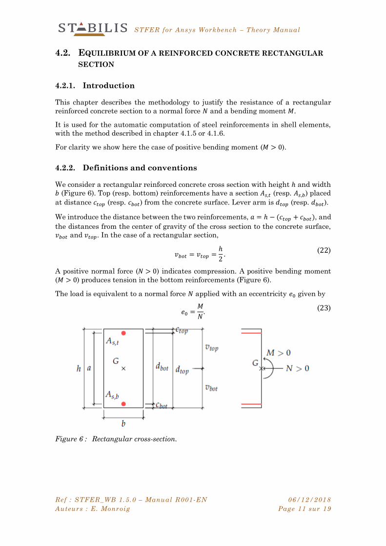
4.2.2. Definitions and conventions
We consider a rectangular reinforced concrete cross section with height ℎ and width
𝑏 (Figure 6). Top (resp. bottom) reinforcements have a section 𝐴𝑠,𝑡 (resp. 𝐴𝑠,𝑏) placed
at distance 𝑐𝑡𝑜𝑝 (resp. 𝑐𝑏𝑜𝑡) from the concrete surface. Lever arm is ⅆ𝑡𝑜𝑝 (resp. ⅆ𝑏𝑜𝑡).
We introduce the distance between the two reinforcements, 𝑎 = ℎ − (𝑐𝑡𝑜𝑝 + 𝑐𝑏𝑜𝑡), and
the distances from the center of gravity of the cross section to the concrete surface,
𝑣𝑏𝑜𝑡 and 𝑣𝑡𝑜𝑝. In the case of a rectangular section,
𝑣𝑏𝑜𝑡 = 𝑣𝑡𝑜𝑝 =
ℎ
2.
(22)
A positive normal force (𝑁 > 0) indicates compression. A positive bending moment
(𝑀 > 0) produces tension in the bottom reinforcements (Figure 6).
The load is equivalent to a normal force 𝑁 applied with an eccentricity 𝑒0 given by
𝑒0 =
𝑀
𝑁.
(23)
Figure 6 : Rectangular cross-section.

STFER for Ansys Workbench – Theory Manual
Ref : STFER_WB 1.5.0 – Manual R001-EN 06/12/2018
Auteurs : E. Monroig Page 12 sur 19
4.2.3. Equilibrium equations
External forces are resisted by:
– 𝑁𝑐 ≥ 0 : compression force in concrete;
– 𝑁𝑠,𝑏 : tension (≤ 0) or compression (> 0) in bottom reinforcements;
– 𝑁𝑠,𝑡 : tension (≤ 0) or compression (> 0) in top reinforcements.
The bending moment at bottom reinforcement position is
𝑀/𝐴𝑠,𝑏= 𝑁 ⋅ (𝑣𝑏𝑜𝑡 − 𝑐𝑏𝑜𝑡) + 𝑀 = 𝑁 ⋅ 𝑒𝑏 , (24)
where 𝑒𝑏 = 𝑣𝑏𝑜𝑡 − 𝑐𝑏𝑜𝑡 + 𝑒0 is the eccentricity of the normal force with respect to
bottom reinforcements.
The equilibrium conditions at bottom reinforcement position thus read:
𝑁 = 𝑁𝑐 + 𝑁𝑠,𝑏 + 𝑁𝑠,𝑡 (25)
𝑀/𝐴𝑠,𝑏= 𝑁 ⋅ 𝑒𝑏 = 𝑁𝑐 ⋅ 𝑧 + 𝑁𝑠,𝑡 ⋅ 𝑎. (26)
The software computes the equilibrium of the section and determines the state of
the section (strain and stress profile in concrete and reinforcements), as well as the
reinforcement areas 𝐴𝑠,𝑏 et 𝐴𝑠,𝑡 that are sufficient to satisfy Equations (25) and (26).
Design criteria are enforced using behavior laws specific to the limit state and to the
design code used (refer to the following chapters).
When several choices of 𝐴𝑠,𝑏 and 𝐴𝑠,𝑡 are possible, an optimization is performed to
minimize the total area 𝐴𝑠,𝑏 + 𝐴𝑠,𝑡.
Call 𝛼 = 𝑥𝑢/ⅆ𝑏𝑜𝑡 the height of concrete in compression divided by the bottom
reinforcement lever arm. Depending on the value of 𝛼, the cross-section can be in one
of the following three states:
1. Section is entirely in tension: in this case the only resisting forces are tension
forces in the reinforcements.
2. Section is partly in compression and partly in tension: in this case the
equilibrium is obtained by using both concrete and reinforcements. For high
values of 𝛼, the stress in bottom reinforcement may become less than yield
stress, in which case it may be more economical or even necessary to use top
reinforcements in compression.
3. Section is entirely in compression: in this case the equilibrium is generally
obtained by concrete alone without reinforcements. However, if the concrete
stress or strain exceed the design criteria, the software computes the bottom
and top reinforcement areas that are necessary to remain within the design
criteria.
STFER for Ansys Workbench – Theory Manual
Ref : STFER_WB 1.5.0 – Manual R001-EN 06/12/2018
Auteurs : E. Monroig Page 13 sur 19
4.2.4. Available behavior laws
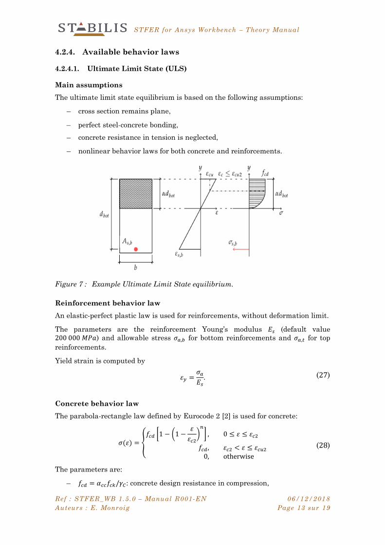
4.2.4.1. Ultimate Limit State (ULS)
Main assumptions
The ultimate limit state equilibrium is based on the following assumptions:
– cross section remains plane,
– perfect steel-concrete bonding,
– concrete resistance in tension is neglected,
– nonlinear behavior laws for both concrete and reinforcements.
Figure 7 : Example Ultimate Limit State equilibrium.
Reinforcement behavior law
An elastic-perfect plastic law is used for reinforcements, without deformation limit.
The parameters are the reinforcement Young’s modulus 𝐸𝑠 (default value
200 000 𝑀𝑃𝑎) and allowable stress 𝜎𝑎,𝑏 for bottom reinforcements and 𝜎𝑎,𝑡 for top
reinforcements.
Yield strain is computed by
𝜀𝑦 =𝜎𝑎
𝐸𝑠. (27)
Concrete behavior law
The parabola-rectangle law defined by Eurocode 2 [2] is used for concrete:
𝜎(𝜀) = {𝑓𝑐𝑑 [1 − (1 −
𝜀
𝜀𝑐2)
𝑛
] , 0 ≤ 𝜀 ≤ 𝜀𝑐2
𝑓𝑐𝑑 , 𝜀𝑐2 < 𝜀 ≤ 𝜀𝑐𝑢2
0, otherwise
(28)
The parameters are:
– 𝑓𝑐𝑑 = 𝛼𝑐𝑐𝑓𝑐𝑘/𝛾𝐶: concrete design resistance in compression,
STFER for Ansys Workbench – Theory Manual
Ref : STFER_WB 1.5.0 – Manual R001-EN 06/12/2018
Auteurs : E. Monroig Page 14 sur 19
– 𝜀𝑐2: strain corresponding to maximal stress (default value 0.2%),
– 𝜀𝑐𝑢2: ultimate design strain (default value 0.35%),
– 𝑛: exponent (default value 2).
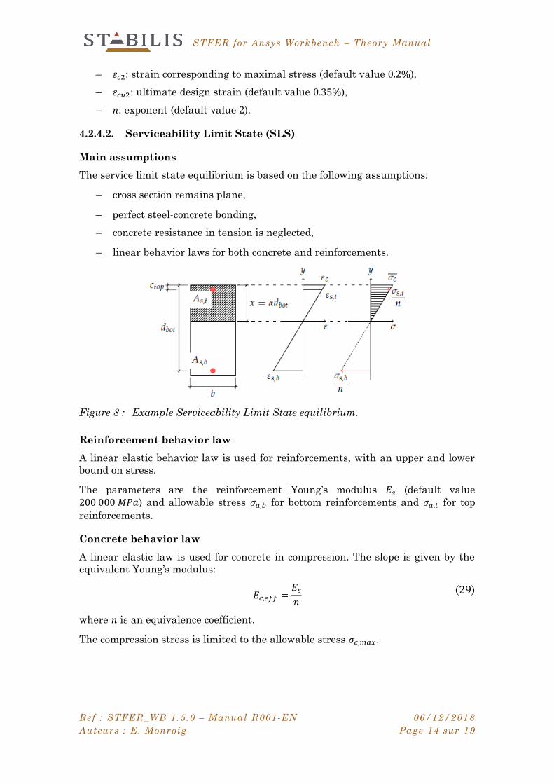
4.2.4.2. Serviceability Limit State (SLS)
Main assumptions
The service limit state equilibrium is based on the following assumptions:
– cross section remains plane,
– perfect steel-concrete bonding,
– concrete resistance in tension is neglected,
– linear behavior laws for both concrete and reinforcements.
Figure 8 : Example Serviceability Limit State equilibrium.
Reinforcement behavior law
A linear elastic behavior law is used for reinforcements, with an upper and lower
bound on stress.
The parameters are the reinforcement Young’s modulus 𝐸𝑠 (default value
200 000 𝑀𝑃𝑎) and allowable stress 𝜎𝑎,𝑏 for bottom reinforcements and 𝜎𝑎,𝑡 for top
reinforcements.
Concrete behavior law
A linear elastic law is used for concrete in compression. The slope is given by the
equivalent Young’s modulus:
𝐸𝑐,𝑒𝑓𝑓 =𝐸𝑠
𝑛
(29)
where 𝑛 is an equivalence coefficient.
The compression stress is limited to the allowable stress 𝜎𝑐,𝑚𝑎𝑥.
STFER for Ansys Workbench – Theory Manual
Ref : STFER_WB 1.5.0 – Manual R001-EN 06/12/2018
Auteurs : E. Monroig Page 15 sur 19
5. TRANSVERSE REINFORCEMENTS
5.1. MAXIMUM TRANSVERSE SHEAR FORCE
The two transverse shear forces per unit length are used to determine the transverse
shear force per unit length for each angle 𝜃 (see also chapter 4.1.5),
𝑄𝜃 = 𝑄𝑥 cos 𝜃 + 𝑄𝑦 sin 𝜃, (30)
which is used to verify the resistance according to the following methodology.
5.2. EUROCODE 2
Resistance to transverse shear force is verified according to Eurocode 2 [2] chapter
6.2.
The computation results are given in the following units:
– transverse reinforcement area per unit area: 𝑐𝑚2/𝑚2,
– concrete shear stress: 𝑀𝑃𝑎.
5.2.1. Notations
The shear force is rewritten more conveniently in the form of an equivalent shear
stress,
𝜏𝑢 =
|𝑉𝐸𝑑|
𝑏𝑤 ⋅ ⅆ
(31)
where 𝑏𝑤 = 1 𝑚 (unit width) and ⅆ is ⅆ𝑏𝑜𝑡 or ⅆ𝑡𝑜𝑝 depending on the sign of the bending
moment.
5.2.2. Resistance of concrete alone
The design shear resistance of concrete, 𝑉𝑅𝑑,𝑐, is computed according to article 6.2.2
Equation (6.2) rewritten below in the form of a shear stress:
𝜏𝑅𝑑,𝑐 = max(𝑣; 𝑣𝑚𝑖𝑛) + 𝑘1𝜎𝑐𝑝 (32)
𝑣 = 𝐶𝑅𝑑,𝑐 ⋅ 𝑘 ⋅ (100 𝜌𝑙 𝑓𝑐𝑘)13 (33)
where:
– the mean compression stress is 𝜎𝑐𝑝 = 𝑁/𝐴𝐶, with upper bound 0,2 𝑓𝑐𝑑,
– 𝐴𝐶 is the area of the concrete section,
– the height ℎ is equal to the thickness of the shell or plate element,
– 𝜌𝑙 is computed from the reinforcement areas computed in chapter 4 for the
current combination, as the minimum value between 𝐴𝑋 and 𝐴𝑌. These
STFER for Ansys Workbench – Theory Manual
Ref : STFER_WB 1.5.0 – Manual R001-EN 06/12/2018
Auteurs : E. Monroig Page 16 sur 19
reinforcements are supposed to be anchored at a distance 𝑙𝑏𝑑 + ⅆ. When 𝑀 ≥0, the bottom reinforcements are used; when 𝑀 < 0, the top reinforcements
are used. In both cases 𝜌𝑙 has an upper bound of 2%,
– the recommended values for 𝑘, 𝐶𝑅𝑑,𝑐 et 𝑘1 are used:
𝑘1 = 0,15 (34)
𝑘 = min (1 + √
0,2
ⅆ ; 2) (35)
𝐶𝑅𝑑,𝑐 =
0,18
𝛾𝐶 (36)
– 𝑣𝑚𝑖𝑛 is defined according to national annex (NF EN 1992-1-1/NA §6.2.2 (1)
NOTE), with a formula chosen by the user (See User Manual [1], property
“Transverse Redistribution”):
– Slabs with transverse redistribution (flag_v = 0):
𝑣𝑚𝑖𝑛 = 0,23 ⋅ 𝑓𝑐𝑘1/2
– Beams and slabs without transverse redistribution (flag_v = 1):
𝑣𝑚𝑖𝑛 = 0,035 ⋅ 𝑘3/2 ⋅ 𝑓𝑐𝑘1/2
– Walls (flag_v = 2):
𝑣𝑚𝑖𝑛 = 0,23 ⋅ 𝑓𝑐𝑘1/2
When 𝑉𝐸𝑑 ≤ 𝑉𝑅𝑑,𝑐 and 𝑉𝐸𝑑 ≤ 𝑉𝑅𝑑,𝑚𝑎𝑥 computed according to Equation (6.5), transverse
reinforcements are not necessary. If any of these two conditions is not satisfied,
necessary transverse reinforcements are computed according to the following
chapter.
Equation (6.5) is reproduced below in the form of a maximum equivalent shear stress
𝜏𝑅𝑑,𝑚𝑎𝑥 = 0,5 ⋅ 𝜈 ⋅ 𝑓𝑐𝑑 (37)
with
𝜈 = 0.6 (1 −
𝑓𝑐𝑘
250)
(38)
5.2.3. Resistance with transverse reinforcements
5.2.3.1. Verification of compression stress in concrete struts
Compression stress in concrete struts is verified by comparing the acting force 𝑉𝐸𝑑
to the resisting force 𝑉𝑅𝑑,𝑚𝑎𝑥, computed according to article 6.2.3 Equation (6.9),
rewritten below in the form of a maximum equivalent shear stress:
𝜏𝑅𝑑,𝑚𝑎𝑥 =
0,9 ⋅ 𝛼𝑐𝑤 ⋅ 𝜈1 ⋅ 𝑓𝑐𝑑
𝑐𝑜𝑡(𝜃) + tan(𝜃)
(39)
STFER for Ansys Workbench – Theory Manual
Ref : STFER_WB 1.5.0 – Manual R001-EN 06/12/2018
Auteurs : E. Monroig Page 17 sur 19
where:
– the lever arm 𝑧 is taken equal to 0,9 ⅆ,
– the angle of transverse rebars is 𝛼 = 90°,
– the angle of concrete struts is 𝜃 = 45°,
– the coefficient ν1 that reduces the resistance of cracked concrete to shear
forces is computed as follows (See User Manual [1], property “Method
Calculation For nu_1”):
– Equal to nu (flag_nu = 0): apply article 6.2.3(3) NOTE 1, giving
𝜈1 = 𝜈;
– Alternative method (flag_nu = 1) apply article 6.2.3(3) NOTE 2
Equations (6.10aN) and (6.10bN), giving:
– 𝜈1 = 0,6 for 𝑓𝑐𝑘 ≤ 60 𝑀𝑃𝑎
– 𝜈1 = max (0,9 −𝑓𝑐𝑘
200; 0,5) for 𝑓𝑐𝑘 > 60 𝑀𝑃𝑎
and use 0.8 𝑓𝑦𝑤𝑑 instead of 𝑓𝑦𝑤𝑑 in §5.2.3.2,
– the coefficient 𝛼𝑐𝑤 is defined according to national annex recommendations
(NF EN 1992-1-1/NA §6.2.3 (3) NOTES 1 à 3):
– 𝛼𝑐𝑤 = 1 if 0 ≤ 𝜎𝑐𝑝
– 𝛼𝑐𝑤 = 1 +𝜎𝑐𝑝
𝑓𝑐𝑡𝑚 if −𝑓𝑐𝑡𝑚 ≤ 𝜎𝑐𝑝 < 0
– 𝛼𝑐𝑤 = 0 if 𝜎𝑐𝑝 < −𝑓𝑐𝑡𝑚
For the specific case of a section entirely in tension, the coefficient is 0 and
thus 𝑉𝑅𝑑,𝑚𝑎𝑥 = 𝑉𝑅𝑑,𝑐 = 0 (this case is not handled by Eurocode).
5.2.3.2. Necessary transverse reinforcements
The necessary transverse reinforcement area per unit area is computed according to
article 6.2.3 Equation (6.8), which we reproduce below using equivalent shear stress:
𝐴𝑠𝑤
𝑠=
𝑏𝑤 ⋅ 𝜏𝑢
0,9 ⋅ 𝑓𝑦𝑤𝑑 ⋅ 𝑐𝑜𝑡(𝜃)
(40)
If the compression stress of concrete struts is not verified (see §5.2.3.1), the
transverse reinforcement area is not computed and is replaced by value 999 𝑐𝑚2/𝑚2
(error code).
5.2.4. Shear combined with tension
In the case of shear combined with tension, the coefficient 𝛼𝑐𝑤 is equal to 0 (see
§5.2.3.1). The resistance of the section cannot be assessed by using the Eurocode
equations.
In this case, the transverse reinforcement area is replaced by an arbitrary value
999 𝑐𝑚2/𝑚2 (error code).
STFER for Ansys Workbench – Theory Manual
Ref : STFER_WB 1.5.0 – Manual R001-EN 06/12/2018
Auteurs : E. Monroig Page 18 sur 19
5.2.5. Results
The following results are available as fields in Ansys Mechanical:
– transverse reinforcement area per unit area (𝐴𝑠𝑤
𝑠), see §5.2.3.2;
– concrete equivalent shear stress (𝜏𝑢), see §5.2.1;
– concrete resistant shear stress (𝜏𝑅𝑑,𝑐), see §5.2.2;
– concrete maximal shear stress (𝜏𝑅𝑑,𝑚𝑎𝑥), see §5.2.2 and §5.2.3.1.
STFER for Ansys Workbench – Theory Manual
Ref : STFER_WB 1.5.0 – Manual R001-EN 06/12/2018
Auteurs : E. Monroig Page 19 sur 19
6. BIBLIOGRAPHY
[1] Reinforcement Design V1.0 – User Manual. Phimeca Engineering and
Stabilis, December 2018.
[2] NF EN 1992-1-1: Eurocode 2 – design of concrete structures – Part 1-1: general
rules and rules for buildings.
[3] NF EN 1992-1-1/NA: Eurocode 2: Design of concrete structures – Part 1-1:
General rules and rules for buildings – National annex to NF EN 1992-1-1:2005
– General rules and rules for buildings.
[4] Alain CAPRA et Jean-Francis MAURY : Calcul automatique du ferraillage
optimal des plaques ou coques en béton armé. 36(367). ISSN 0020-2568.
[5] Jean-Marie PAILLE. Calcul des structures en béton : Guide d'application de
l'Eurocode 2. 3e Edition, AFNOR / Eyrolles, 2016.


