52
{ STIHL FS 240, 240 R, 260 R Instruction Manual

{
STIHL FS 240, 240 R, 260 R
Instruction Manual
Orig
inal
Inst
ruct
ion
Man
ual
Prin
ted
on c
hlor
ine-
free
pape
rPr
intin
g in
ks c
onta
in v
eget
able
oils
, pap
er c
an b
e re
cycl
ed.
© A
ND
REA
S ST
IHL
AG &
Co.
KG
, 201
604
58-7
42-0
121-
E. V
A0.B
16.
English
Contents
007107
_004
_GB
Dear Customer,Thank you for choosing a quality engineered STIHL product.It has been built using modern production techniques and comprehensive quality assurance. Every effort has been made to ensure your satisfaction and troublefree use of the product.Please contact your dealer or our sales company if you have any queries concerning this product.Your
Dr. Nikolas Stihl
Guide to Using this Manual 2Safety Precautions and Working Techniques 2Approved Combinations of Cutting Attachment, Deflector, Handle and Harness 12Approved Power Tool Attachments 13Mounting the Bike Handle 14Mounting the Loop Handle 16Fitting the Carrying Ring 18Adjusting the Throttle Cable 18Mounting the deflector 19Mounting the Cutting Attachment 20Fuel 22Fueling 24Fitting the Harness 24Balancing the Machine 26Starting / Stopping the Engine 27Mounting the Transport Guard 29Operating Instructions 32Air filter 32Adjusting the Carburetor 33Winter Operation 33Spark Plug 35Engine Running Behavior 36Lubricating the Gearbox 36Storing the Machine 37Sharpening Metal Cutting Blades 37Maintaining the Mowing Head 38Maintenance and Care 40Minimize Wear and Avoid Damage 42Main Parts 43
Specifications 45Maintenance and Repairs 46Disposal 47EC Declaration of Conformity 47
0000
FS 240, FS 240 C, FS 240 R, FS 240 RC, FS 260 R, FS 260 RC 1
{ This instruction manual is protected by copyright. All rights reserved, especially the rights to reproduce, translate and process with electronic systems.
English
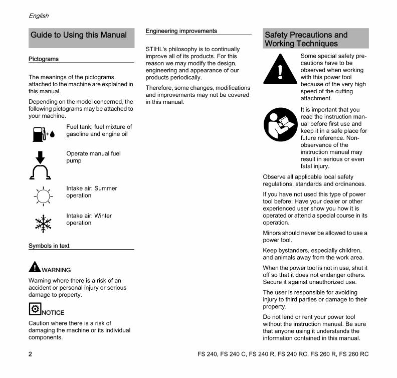
Pictograms
The meanings of the pictograms attached to the machine are explained in this manual.Depending on the model concerned, the following pictograms may be attached to your machine.
Symbols in text
WARNINGWarning where there is a risk of an accident or personal injury or serious damage to property.
NOTICECaution where there is a risk of damaging the machine or its individual components.
Engineering improvements
STIHL's philosophy is to continually improve all of its products. For this reason we may modify the design, engineering and appearance of our products periodically.Therefore, some changes, modifications and improvements may not be covered in this manual.
Observe all applicable local safety regulations, standards and ordinances.If you have not used this type of power tool before: Have your dealer or other experienced user show you how it is operated or attend a special course in its operation.Minors should never be allowed to use a power tool.Keep bystanders, especially children, and animals away from the work area.When the power tool is not in use, shut it off so that it does not endanger others. Secure it against unauthorized use.The user is responsible for avoiding injury to third parties or damage to their property.Do not lend or rent your power tool without the instruction manual. Be sure that anyone using it understands the information contained in this manual.
Guide to Using this Manual
Fuel tank; fuel mixture of gasoline and engine oil
Operate manual fuel pump
Intake air: Summer operation
Intake air: Winter operation
Safety Precautions and Working Techniques
Some special safety pre-cautions have to be observed when working with this power tool because of the very high speed of the cutting attachment.
It is important that you read the instruction man-ual before first use and keep it in a safe place for future reference. Non-observance of the instruction manual may result in serious or even fatal injury.
FS 240, FS 240 C, FS 240 R, FS 240 RC, FS 260 R, FS 260 RC2
English
The use of noise emitting power tools may be restricted to certain times by national or local regulations.To operate the power tool you must be rested, in good physical condition and mental health.If you have any condition that might be aggravated by strenuous work, check with your doctor before operating a power tool.Persons with pacemakers only: The ignition system of your power tool produces an electromagnetic field of a very low intensity. This field may interfere with some pacemakers. STIHL recommends that persons with pacemakers consult their physician and the pacemaker manufacturer to reduce any health risk.Do not operate the power tool if you are under the influence of any substance (drugs, alcohol) which might impair vision, dexterity or judgment.Depending on the cutting attachment fitted, use your power tool only for cutting grass, wild growth, shrubs, scrub, bushes, small diameter trees and similar materials. Do not use your power tool for any other purpose because of the increased risk of accidents.Only use cutting attachments and accessories that are explicitly approved for this power tool model by STIHL or are technically identical. If you have any questions in this respect, consult a servicing dealer. Use only high quality tools and accessories in order to avoid the risk of accidents and damage to the machine.
STIHL recommends the use of genuine STIHL tools and accessories. They are specifically designed to match the product and meet your performance requirements.Never attempt to modify your machine in any way since this may increase the risk of personal injury. STIHL excludes all liability for personal injury and damage to property caused while using unauthorized attachments.The deflector on this power tool cannot protect the operator from all objects thrown by the cutting attachment (stones, glass, wire, etc.). Such objects may ricochet and then hit the operator.Do not use a pressure washer to clean your power tool. The solid jet of water may damage parts of the power tool.
Clothing and Equipment
Wear proper protective clothing and equipment.
Avoid clothing that could get caught on branches or brush or moving parts of the machine. Do not wear a scarf, necktie or jewelry. Tie up and confine long hair (e.g. with a hair net, cap, hard hat, etc.).
Sturdy shoes with non-slip soles may be worn as an alternative only when using mowing heads.
WARNING
Wear a face shield and make sure it is a good fit. A face shield alone does not provide adequate eye protection.Wear hearing protection, e.g. earplugs or ear muffs.Wear a safety hard hat for thinning operations, when working in high scrub and where there is a danger of head injuries from falling objects.
STIHL offers a comprehensive range of personal protective clothing and equipment.
Clothing must be sturdy but allow complete free-dom of movement. Wear snug-fitting clothing, an overall and jacket combi-nation, do not wear a work coat.
Wear steel-toed safety boots with non-slip soles.
To reduce the risk of eye injuries, wear close-fit-ting safety glasses in accordance with Euro-pean Standard EN 166. Make sure the safety glasses are a comforta-ble and snug fit.
Wear robust work gloves made of durable material (e.g. leather).
FS 240, FS 240 C, FS 240 R, FS 240 RC, FS 260 R, FS 260 RC 3
English
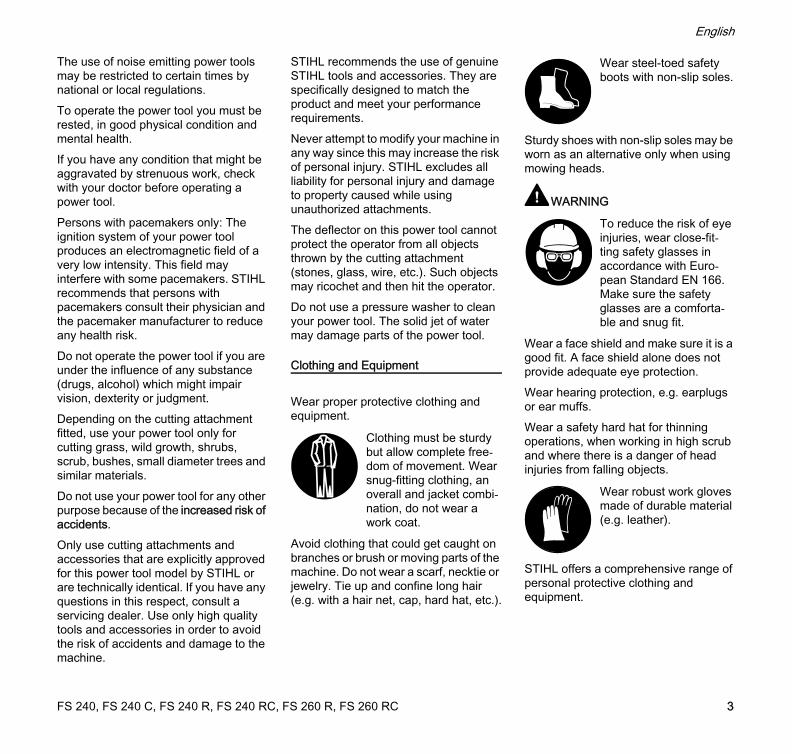
Transporting the Power Tool
Always stop the engine.Carry the unit hanging from the shoulder strap or properly balanced by the drive tube.To reduce the risk of cut injuries, fit transport guard on the cutting attachment, even when carrying the tool for short distances – see also "Mounting the Transport Guard".
Transporting by vehicle: Properly secure your power tool to prevent turnover, fuel spillage and damage.
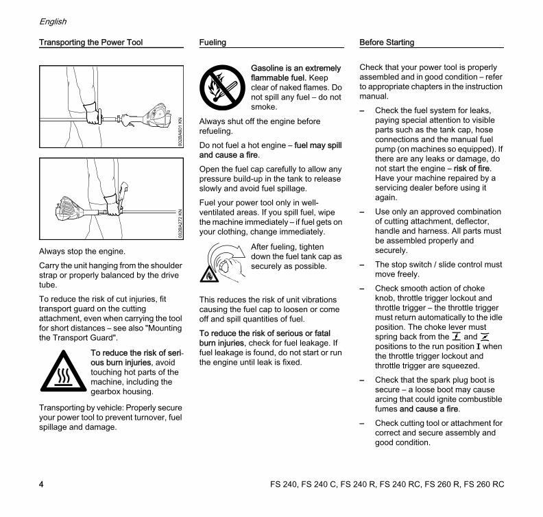
Fueling
Always shut off the engine before refueling.Do not fuel a hot engine – fuel may spill and cause a fire.Open the fuel cap carefully to allow any pressure build-up in the tank to release slowly and avoid fuel spillage.Fuel your power tool only in well-ventilated areas. If you spill fuel, wipe the machine immediately – if fuel gets on your clothing, change immediately.
This reduces the risk of unit vibrations causing the fuel cap to loosen or come off and spill quantities of fuel.To reduce the risk of serious or fatal burn injuries, check for fuel leakage. If fuel leakage is found, do not start or run the engine until leak is fixed.
Before Starting
Check that your power tool is properly assembled and in good condition – refer to appropriate chapters in the instruction manual.– Check the fuel system for leaks,
paying special attention to visible parts such as the tank cap, hose connections and the manual fuel pump (on machines so equipped). If there are any leaks or damage, do not start the engine – risk of fire. Have your machine repaired by a servicing dealer before using it again.
– Use only an approved combination of cutting attachment, deflector, handle and harness. All parts must be assembled properly and securely.
– The stop switch / slide control must move freely.
– Check smooth action of choke knob, throttle trigger lockout and throttle trigger – the throttle trigger must return automatically to the idle position. The choke lever must spring back from the g and < positions to the run position F when the throttle trigger lockout and throttle trigger are squeezed.
– Check that the spark plug boot is secure – a loose boot may cause arcing that could ignite combustible fumes and cause a fire.
– Check cutting tool or attachment for correct and secure assembly and good condition.
To reduce the risk of seri-ous burn injuries, avoid touching hot parts of the machine, including the gearbox housing.
002B
A60
1 K
N00
2BA2
72 K
N
Gasoline is an extremely flammable fuel. Keep clear of naked flames. Do not spill any fuel – do not smoke.
After fueling, tighten down the fuel tank cap as securely as possible.
FS 240, FS 240 C, FS 240 R, FS 240 RC, FS 260 R, FS 260 RC4
English
– Check protective devices (e.g. deflector for cutting attachment, rider plate) for damage or wear. Always replace damaged parts. Do not operate your machine with a damaged deflector or worn rider plate (lettering and arrows no longer legible).
– Never attempt to modify the controls or safety devices in any way.
– Keep the handles dry and clean – free from oil and dirt – for safe control of the power tool.
– Adjust the harness and handle(s) to suit your height and reach. See chapters on "Fitting the Harness" and "Balancing the Machine".
To reduce the risk of accidents, do not operate your power tool if it is damaged or not properly assembled.If you use a shoulder strap or full harness: Practice removing and putting down the machine as you would in an emergency. To avoid damage, do not throw the machine to the ground when practicing.
Starting the Engine
Start the engine at least 3 meters from the fueling spot, outdoors only.Place the unit on firm ground in an open area. Make sure you have good balance and secure footing. Hold the unit securely. The cutting attachment must be clear of the ground and all other obstructions because it may begin to run when the engine starts.
Your power tool is a one-person unit. To reduce the risk of injury from thrown objects, do not allow other persons within a radius of 15 meters of your own position – even when starting.
Check idle speed setting: The cutting attachment must not rotate when the engine is idling with the throttle trigger released.To reduce the risk of fire, keep hot exhaust gases and hot muffler away from easily combustible materials (e.g. wood chips, bark, dry grass, fuel).
Holding and Controlling the Power Tool
Always hold the power tool firmly with both hands on the handles.Make sure you always have good balance and secure footing.
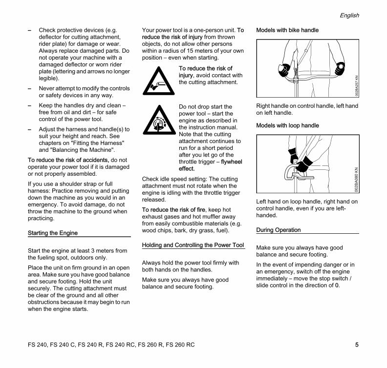
Models with bike handle
Right handle on control handle, left hand on left handle.
Models with loop handle
Left hand on loop handle, right hand on control handle, even if you are left-handed.
During Operation
Make sure you always have good balance and secure footing.In the event of impending danger or in an emergency, switch off the engine immediately – move the stop switch / slide control in the direction of 0.
To reduce the risk of injury, avoid contact with the cutting attachment.
Do not drop start the power tool – start the engine as described in the instruction manual. Note that the cutting attachment continues to run for a short period after you let go of the throttle trigger – flywheel effect.
002B
A257
KN
002B
A08
0 K
N
FS 240, FS 240 C, FS 240 R, FS 240 RC, FS 260 R, FS 260 RC 5
English
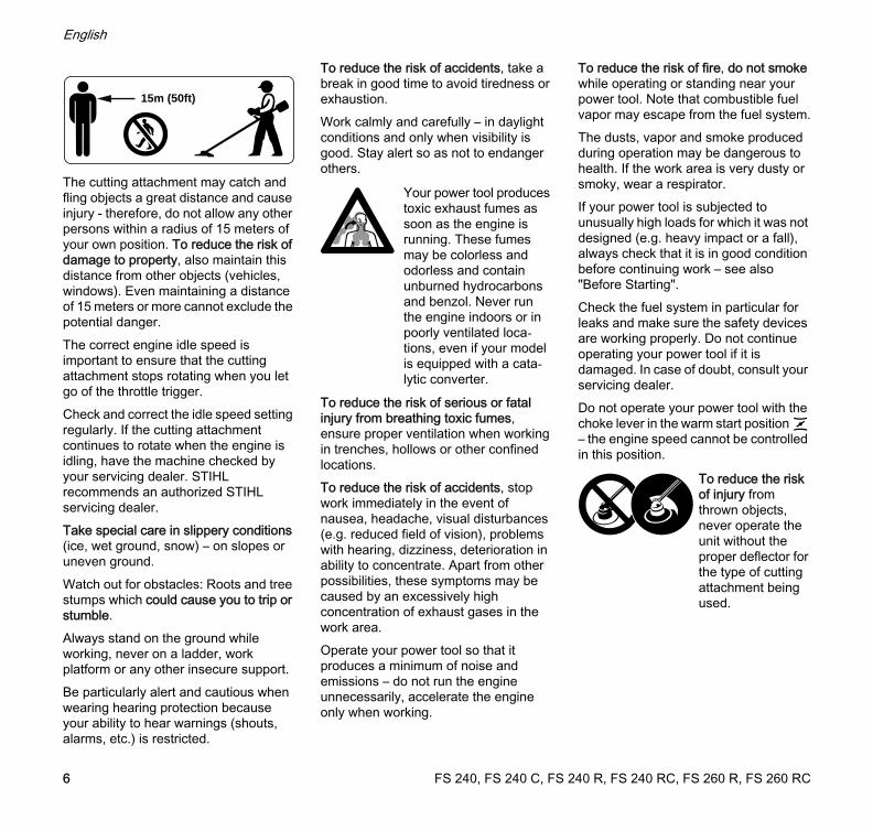
The cutting attachment may catch and fling objects a great distance and cause injury - therefore, do not allow any other persons within a radius of 15 meters of your own position. To reduce the risk of damage to property, also maintain this distance from other objects (vehicles, windows). Even maintaining a distance of 15 meters or more cannot exclude the potential danger.The correct engine idle speed is important to ensure that the cutting attachment stops rotating when you let go of the throttle trigger.Check and correct the idle speed setting regularly. If the cutting attachment continues to rotate when the engine is idling, have the machine checked by your servicing dealer. STIHL recommends an authorized STIHL servicing dealer.Take special care in slippery conditions (ice, wet ground, snow) – on slopes or uneven ground.Watch out for obstacles: Roots and tree stumps which could cause you to trip or stumble.Always stand on the ground while working, never on a ladder, work platform or any other insecure support.Be particularly alert and cautious when wearing hearing protection because your ability to hear warnings (shouts, alarms, etc.) is restricted.
To reduce the risk of accidents, take a break in good time to avoid tiredness or exhaustion.Work calmly and carefully – in daylight conditions and only when visibility is good. Stay alert so as not to endanger others.
To reduce the risk of serious or fatal injury from breathing toxic fumes, ensure proper ventilation when working in trenches, hollows or other confined locations.To reduce the risk of accidents, stop work immediately in the event of nausea, headache, visual disturbances (e.g. reduced field of vision), problems with hearing, dizziness, deterioration in ability to concentrate. Apart from other possibilities, these symptoms may be caused by an excessively high concentration of exhaust gases in the work area.Operate your power tool so that it produces a minimum of noise and emissions – do not run the engine unnecessarily, accelerate the engine only when working.
To reduce the risk of fire, do not smoke while operating or standing near your power tool. Note that combustible fuel vapor may escape from the fuel system.The dusts, vapor and smoke produced during operation may be dangerous to health. If the work area is very dusty or smoky, wear a respirator.If your power tool is subjected to unusually high loads for which it was not designed (e.g. heavy impact or a fall), always check that it is in good condition before continuing work – see also "Before Starting".Check the fuel system in particular for leaks and make sure the safety devices are working properly. Do not continue operating your power tool if it is damaged. In case of doubt, consult your servicing dealer.Do not operate your power tool with the choke lever in the warm start position < – the engine speed cannot be controlled in this position.
15m (50ft)
Your power tool produces toxic exhaust fumes as soon as the engine is running. These fumes may be colorless and odorless and contain unburned hydrocarbons and benzol. Never run the engine indoors or in poorly ventilated loca-tions, even if your model is equipped with a cata-lytic converter.
To reduce the risk of injury from thrown objects, never operate the unit without the proper deflector for the type of cutting attachment being used.
FS 240, FS 240 C, FS 240 R, FS 240 RC, FS 260 R, FS 260 RC6
English
Special care must be taken when working in difficult, over-grown terrain.When cutting high scrub, under bushes and hedges: Keep cutting attachment at a minimum height of 15 cm to avoid harming small animals.Always shut off the engine before leaving the unit unattended.Check the cutting attachment at regular short intervals during operation or immediately if there is a noticeable change in cutting behavior:– Turn off the engine. Hold the unit
firmly and wait for the cutting attachment to come to a standstill.
– Check condition and tightness, look for cracks.
– Check sharpness.– Replace damaged or dull cutting
attachments immediately, even if they have only superficial cracks.
Clean grass and plant residue off the cutting attachment mounting at regular intervals – remove any build up of material from the cutting attachment and deflector.To reduce the risk of injury, shut off the engine before changing the cutting attachment.
When using mowing heads
Equip the deflector with the additional components specified in the instruction manual.Use only the deflector with properly mounted line limiting blade to ensure the mowing lines are automatically trimmed to the approved length.To reduce the risk of injury, always turn off the engine before adjusting the nylon line of manually adjustable mowing headsUsing the unit with over-long nylon cutting lines reduces the motor's operating speed. The clutch then slips continuously and this causes overheating and damage to important components (e.g. clutch, polymer housing components) – and this can increase the risk of injury from the cutting attachment rotating while the engine is idling.
Using metal cutting attachments
STIHL recommends the use of original STIHL metal cutting attachments. They are specifically designed to match your model and meet your performance requirements.Metal cutting attachments rotate at very high speed. The forces that occur act on the machine, the attachment and the material being cut.
Sharpen metal cutting attachments regularly as specified.Unevenly sharpened metal cutting attachments cause out-of-balance which can impose extremely high loads on the machine and increase the risk of breakage.Dull or improperly sharpened cutting edges can put a higher load on the cutting attachment and increase the risk of injury from cracked or broken parts.Inspect metal cutting attachments for cracks or warping after every contact with hard objects (e.g. stones, rocks, pieces of metal). To reduce the risk of injury, remove burrs and other visible build-ups of material (use a file) because they may become detached and be thrown at high speed during operation.If a rotating metal cutting attachment makes contact with a rock or other solid object there is a risk of sparking which may cause easily combustible material to catch fire under certain circumstances. Dry plants and scrub are also easily combustible, especially in hot and dry weather conditions. If there is a risk of fire, do not use metal cutting attachments near combustible materials, dry plants or scrub. Always contact your local forest authority for information on a possible fire risk.Do not continue using or attempt to repair damaged or cracked cutting attachments by welding, straightening or modifying the shape (out of balance).This may cause parts of the cutting attachment to come off and hit the operator or bystanders at high speed and result in serious or fatal injuries.
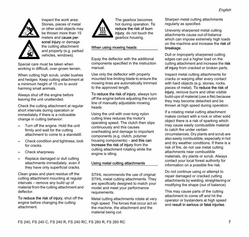
Inspect the work area: Stones, pieces of metal or other solid objects may be thrown more than 15 meters and cause per-sonal injury or damage the cutting attachment and property (e.g. parked vehicles, windows).
The gearbox becomes hot during operation. To reduce the risk of burn injury, do not touch the gearbox housing.
FS 240, FS 240 C, FS 240 R, FS 240 RC, FS 260 R, FS 260 RC 7
English
To reduce the above-mentioned risks when using a metal cutting attachment, never use a metal cutting attachment with a diameter larger than specified. It must not be too heavy. It must be manufactured from materials of adequate quality and its geometry must be correct (shape, thickness).To reduce the risk of injury, a metal cutting attachment not manufactured by STIHL must not be heavier, thicker, have a different shape or a diameter larger than the largest metal cutting attachment approved by STIHL for this power tool model.
Vibrations
Prolonged use of the power tool may result in vibration-induced circulation problems in the hands (whitefinger disease).No general recommendation can be given for the length of usage because it depends on several factors.The period of usage is prolonged by:– Hand protection (wearing warm
gloves)– Work breaksThe period of usage is shortened by:– Any personal tendency to suffer
from poor circulation (symptoms: frequently cold fingers, tingling sensations).
– Low outside temperatures.– The force with which the handles
are held (a tight grip restricts circulation).
Continual and regular users should monitor closely the condition of their hands and fingers. If any of the above symptoms appear (e.g. tingling sensation in fingers), seek medical advice.
Maintenance and Repairs
Service the machine regularly. Do not attempt any maintenance or repair work not described in the instruction manual. Have all other work performed by a servicing dealer.STIHL recommends that you have servicing and repair work carried out exclusively by an authorized STIHL servicing dealer. STIHL dealers are regularly given the opportunity to attend training courses and are supplied with the necessary technical information.Only use high-quality replacement parts in order to avoid the risk of accidents and damage to the machine. If you have any questions in this respect, consult a servicing dealer.STIHL recommends the use of original STIHL replacement parts. They are specifically designed to match your model and meet your performance requirements.To reduce the risk of injury from unintentional engine startup, always shut off the engine and disconnect the spark plug boot before performing any repairs, maintenance or cleaning work. – Exception: Carburetor and idle speed adjustments.
Do not turn the engine over on the starter with the spark plug boot or spark plug removed since there is otherwise a risk of fire from uncontained sparking.To reduce the risk of fire, do not service or store your machine near open flames.Check the fuel filler cap for leaks at regular intervals.Use only a spark plug of the type approved by STIHL and make sure it is in good condition – see "Specifications".Inspect the ignition lead (insulation in good condition, secure connection).Check the condition of the muffler.To reduce the risk of fire and damage to hearing, do not operate your machine if the muffler is damaged or missing. –Do not touch a hot muffler since burn injury will result.Vibration behavior is influenced by the condition of the AV elements – check the AV elements at regular intervals.
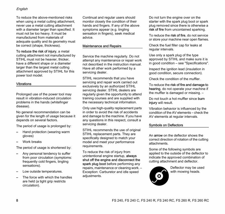
Symbols on Deflectors
An arrow on the deflector shows the correct direction of rotation of the cutting attachments.Some of the following symbols are applied to the outside of the deflector to indicate the approved combination of cutting attachment and deflector.
Deflector may be used with mowing heads.
FS 240, FS 240 C, FS 240 R, FS 240 RC, FS 260 R, FS 260 RC8
English
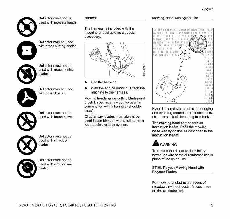
Harness
The harness is included with the machine or available as a special accessory.
N Use the harness.N With the engine running, attach the
machine to the harness.Mowing heads, grass cutting blades and brush knives must always be used in combination with a harness (shoulder strap).Circular saw blades must always be used in combination with a full harness with a quick-release system.
Mowing Head with Nylon Line
Nylon line achieves a soft cut for edging and trimming around trees, fence posts, etc. – less risk of damaging tree bark.The mowing head comes with an instruction leaflet. Refill the mowing head with nylon line as described in the instruction leaflet.
WARNINGTo reduce the risk of serious injury, never use wire or metal-reinforced line in place of the nylon line.
STIHL Polycut Mowing Head with Polymer Blades
For mowing unobstructed edges of meadows (without posts, fences, trees or similar obstacles).
Deflector must not be used with mowing heads.
Deflector may be used with grass cutting blades.
Deflector must not be used with grass cutting blades.
Deflector may be used with brush knives.
Deflector must not be used with brush knives.
Deflector must not be used with shredder blades.
Deflector must not be used with circular saw blades.
002B
A37
7 K
N
000B
A01
5 K
N
FS 240, FS 240 C, FS 240 R, FS 240 RC, FS 260 R, FS 260 RC 9
English
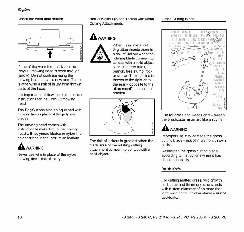
Check the wear limit marks!
If one of the wear limit marks on the PolyCut mowing head is worn through (arrow): Do not continue using the mowing head. Install a new one. There is otherwise a risk of injury from thrown parts of the head.It is important to follow the maintenance instructions for the PolyCut mowing head.The PolyCut can also be equipped with mowing line in place of the polymer blades.The mowing head comes with instruction leaflets. Equip the mowing head with polymers blades or nylon line as described in the instruction leaflets.
WARNINGNever use wire in place of the nylon mowing line – risk of injury.
Risk of Kickout (Blade Thrust) with Metal Cutting Attachments
WARNING
The risk of kickout is greatest when the black area of the rotating cutting attachment comes into contact with a solid object.
Grass Cutting Blade
Use for grass and weeds only – sweep the brushcutter in an arc like a scythe.
WARNINGImproper use may damage the grass cutting blade – risk of injury from thrown parts.Resharpen the grass cutting blade according to instructions when it has dulled noticeably.
Brush Knife
For cutting matted grass, wild growth and scrub and thinning young stands with a stem diameter of no more than 2 cm – do not cut thicker stems – risk of accidents.
002B
A04
9 K
N When using metal cut-ting attachments there is a risk of kickout when the rotating blade comes into contact with a solid object such as a tree trunk, branch, tree stump, rock or similar. The machine is thrown to the right or to the rear – opposite to the attachment's direction of rotation.
002B
A13
5 K
N
000B
A02
0 K
N
FS 240, FS 240 C, FS 240 R, FS 240 RC, FS 260 R, FS 260 RC10
English
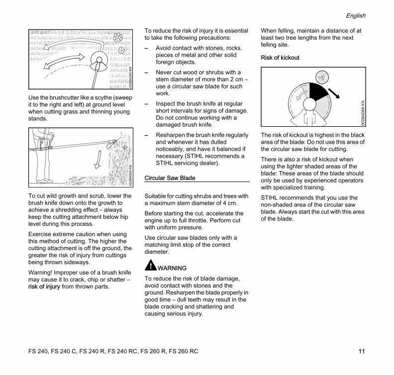
Use the brushcutter like a scythe (sweep it to the right and left) at ground level when cutting grass and thinning young stands.
To cut wild growth and scrub, lower the brush knife down onto the growth to achieve a shredding effect – always keep the cutting attachment below hip level during this process.Exercise extreme caution when using this method of cutting. The higher the cutting attachment is off the ground, the greater the risk of injury from cuttings being thrown sideways.Warning! Improper use of a brush knife may cause it to crack, chip or shatter – risk of injury from thrown parts.
To reduce the risk of injury it is essential to take the following precautions:– Avoid contact with stones, rocks,
pieces of metal and other solid foreign objects.
– Never cut wood or shrubs with a stem diameter of more than 2 cm – use a circular saw blade for such work.
– Inspect the brush knife at regular short intervals for signs of damage. Do not continue working with a damaged brush knife.
– Resharpen the brush knife regularly and whenever it has dulled noticeably, and have it balanced if necessary (STIHL recommends a STIHL servicing dealer).
Circular Saw Blade
Suitable for cutting shrubs and trees with a maximum stem diameter of 4 cm.Before starting the cut, accelerate the engine up to full throttle. Perform cut with uniform pressure.Use circular saw blades only with a matching limit stop of the correct diameter.
WARNINGTo reduce the risk of blade damage, avoid contact with stones and the ground. Resharpen the blade properly in good time – dull teeth may result in the blade cracking and shattering and causing serious injury.
When felling, maintain a distance of at least two tree lengths from the next felling site.
Risk of kickout
The risk of kickout is highest in the black area of the blade: Do not use this area of the circular saw blade for cutting.There is also a risk of kickout when using the lighter shaded areas of the blade: These areas of the blade should only be used by experienced operators with specialized training.STIHL recommends that you use the non-shaded area of the circular saw blade. Always start the cut with this area of the blade.
002B
A35
5 K
N00
2BA
509
KN
002B
A06
8 K
N
FS 240, FS 240 C, FS 240 R, FS 240 RC, FS 260 R, FS 260 RC 11

English
Approved Combinations of Cutting Attachment, Deflector, Handle and Harness
Cutting Attachment Deflector, Limit Stop Handle Shoulder Strap/Harness
21
20
17
19
18
28
2726
26 2724
24
22
0000
-GX
X-0
366-
A1
1 2
3
5
7
15 16
23
25
23
25
25
6
8 9
10 11
1312
4
14
FS 240, FS 240 C, FS 240 R, FS 240 RC, FS 260 R, FS 260 RC12
English
Approved Combinations
Select correct combination from the table according to the cutting attachment you intend to use.
WARNINGFor safety reasons only the cutting attachments, deflectors, handles and harnesses shown in each row of the table may be used together. No other combinations are permitted because of the risk of accidents.
Cutting Attachments
Mowing heads
1 STIHL SuperCut 20-22 STIHL AutoCut 25-23 STIHL AutoCut 30-24 STIHL AutoCut 36-25 STIHL TrimCut 31-26 STIHL DuroCut 20-27 STIHL PolyCut 20-3
Metal cutting attachments
8 Grass cutting blade 230-2(230 mm dia.)
9 Grass cutting blade 260-2(260 mm dia.)
10 Grass cutting blade 230-4(230 mm dia.)
11 Grass cutting blade 230-8(230 mm dia.)
12 Grass cutting blade 250-40 Spezial(250 mm dia.)
13 Grass cutting blade 250-44(250 mm dia.)
14 Brush knife 250-3(250 mm dia.)
15 Scratcher tooth circular saw blade 200(200 mm dia.)
16 Chisel tooth circular saw blade 200(200 mm dia.)
WARNINGNon-metal grass cutting blades, brush knives and circular saw blades are not approved.
Deflectors, Limit Stop
17 Deflector for mowing heads18 Deflector with19 skirt and blade, for mowing heads20 Deflector without skirt and blade, for
metal cutting attachments, items 8 to 14
21 Limit stop for circular saw blades
Handles
22 Loop handle 23 Loop handle with24 barrier bar25 Bicycle handle
Harness
26 Shoulder strap must be used27 Full harness may be used28 Full harness must be used
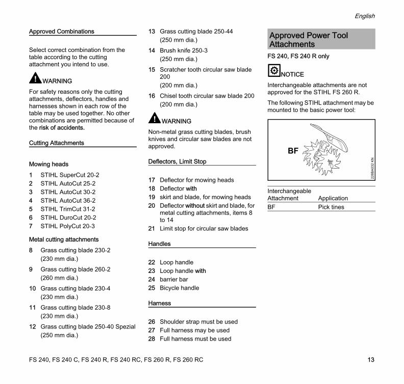
FS 240, FS 240 R only
NOTICEInterchangeable attachments are not approved for the STIHL FS 260 R.The following STIHL attachment may be mounted to the basic power tool:
Approved Power Tool Attachments
Interchangeable Attachment ApplicationBF Pick tines
228B
A03
2 K
N
BF
FS 240, FS 240 C, FS 240 R, FS 240 RC, FS 260 R, FS 260 RC 13
English
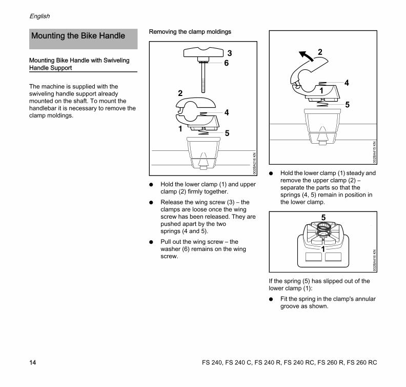
Mounting Bike Handle with Swiveling Handle Support
The machine is supplied with the swiveling handle support already mounted on the shaft. To mount the handlebar it is necessary to remove the clamp moldings.
Removing the clamp moldings
N Hold the lower clamp (1) and upper clamp (2) firmly together.
N Release the wing screw (3) – the clamps are loose once the wing screw has been released. They are pushed apart by the two springs (4 and 5).
N Pull out the wing screw – the washer (6) remains on the wing screw.
N Hold the lower clamp (1) steady and remove the upper clamp (2) – separate the parts so that the springs (4, 5) remain in position in the lower clamp.
If the spring (5) has slipped out of the lower clamp (1):N Fit the spring in the clamp's annular
groove as shown.
Mounting the Bike Handle
2
14
5
002B
A41
5 K
N
1
5
002B
A41
6 K
N
FS 240, FS 240 C, FS 240 R, FS 240 RC, FS 260 R, FS 260 RC14
English
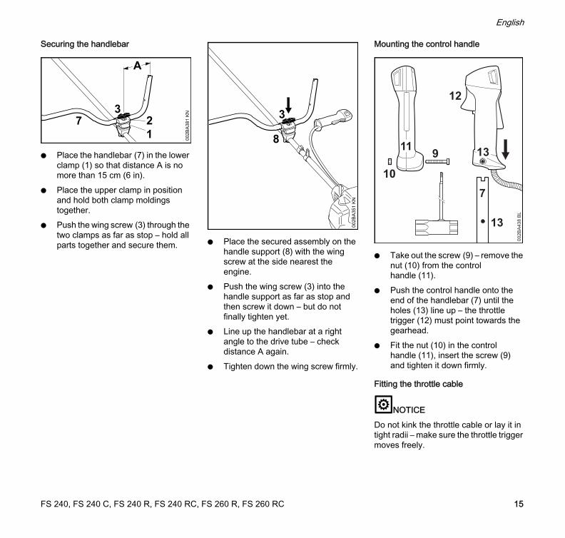
Securing the handlebar
N Place the handlebar (7) in the lower clamp (1) so that distance A is no more than 15 cm (6 in).
N Place the upper clamp in position and hold both clamp moldings together.
N Push the wing screw (3) through the two clamps as far as stop – hold all parts together and secure them. N Place the secured assembly on the
handle support (8) with the wing screw at the side nearest the engine.
N Push the wing screw (3) into the handle support as far as stop and then screw it down – but do not finally tighten yet.
N Line up the handlebar at a right angle to the drive tube – check distance A again.
N Tighten down the wing screw firmly.
Mounting the control handle
N Take out the screw (9) – remove the nut (10) from the control handle (11).
N Push the control handle onto the end of the handlebar (7) until the holes (13) line up – the throttle trigger (12) must point towards the gearhead.
N Fit the nut (10) in the control handle (11), insert the screw (9) and tighten it down firmly.
Fitting the throttle cable
NOTICEDo not kink the throttle cable or lay it in tight radii – make sure the throttle trigger moves freely.
A
37
002B
A38
1 K
N
12 3
002B
A35
1 K
N
813911
12
7
13
002B
A43
8 B
L
10
FS 240, FS 240 C, FS 240 R, FS 240 RC, FS 260 R, FS 260 RC 15
English
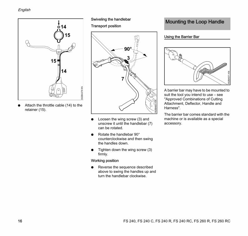
N Attach the throttle cable (14) to the retainer (15).
Swiveling the handlebar
Transport position
N Loosen the wing screw (3) and unscrew it until the handlebar (7) can be rotated.
N Rotate the handlebar 90° counterclockwise and then swing the handles down.
N Tighten down the wing screw (3) firmly.
Working positionN Reverse the sequence described
above to swing the handles up and turn the handlebar clockwise.
Using the Barrier Bar
A barrier bar may have to be mounted to suit the tool you intend to use – see "Approved Combinations of Cutting Attachment, Deflector, Handle and Harness".The barrier bar comes standard with the machine or is available as a special accessory.
14
15
002B
A37
8 K
N
15
147
3
002B
A65
1 K
N
Mounting the Loop Handle
002B
A57
1 K
N
FS 240, FS 240 C, FS 240 R, FS 240 RC, FS 260 R, FS 260 RC16
English
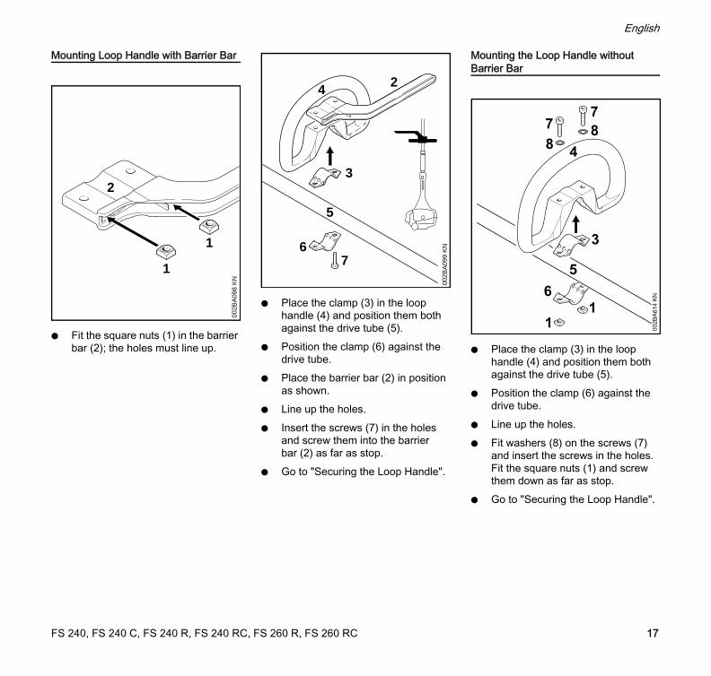
Mounting Loop Handle with Barrier Bar
N Fit the square nuts (1) in the barrier bar (2); the holes must line up.
N Place the clamp (3) in the loop handle (4) and position them both against the drive tube (5).
N Position the clamp (6) against the drive tube.
N Place the barrier bar (2) in position as shown.
N Line up the holes.N Insert the screws (7) in the holes
and screw them into the barrier bar (2) as far as stop.
N Go to "Securing the Loop Handle".
Mounting the Loop Handle without Barrier Bar
N Place the clamp (3) in the loop handle (4) and position them both against the drive tube (5).
N Position the clamp (6) against the drive tube.
N Line up the holes.N Fit washers (8) on the screws (7)
and insert the screws in the holes. Fit the square nuts (1) and screw them down as far as stop.
N Go to "Securing the Loop Handle".
2
002B
A09
8 K
N
1
1
5
4
002B
A09
9 K
N
2
3
67
78
5
4
16
1
3
87
002B
A61
4 K
N
FS 240, FS 240 C, FS 240 R, FS 240 RC, FS 260 R, FS 260 RC 17
English
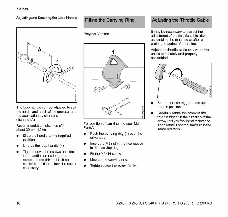
Adjusting and Securing the Loop Handle
The loop handle can be adjusted to suit the height and reach of the operator and the application by changing distance (A).Recommendation: distance (A): about 30 cm (12 in)N Slide the handle to the required
position.N Line up the loop handle (4).N Tighten down the screws until the
loop handle can no longer be rotated on the drive tube. If no barrier bar is fitted – lock the nuts if necessary.
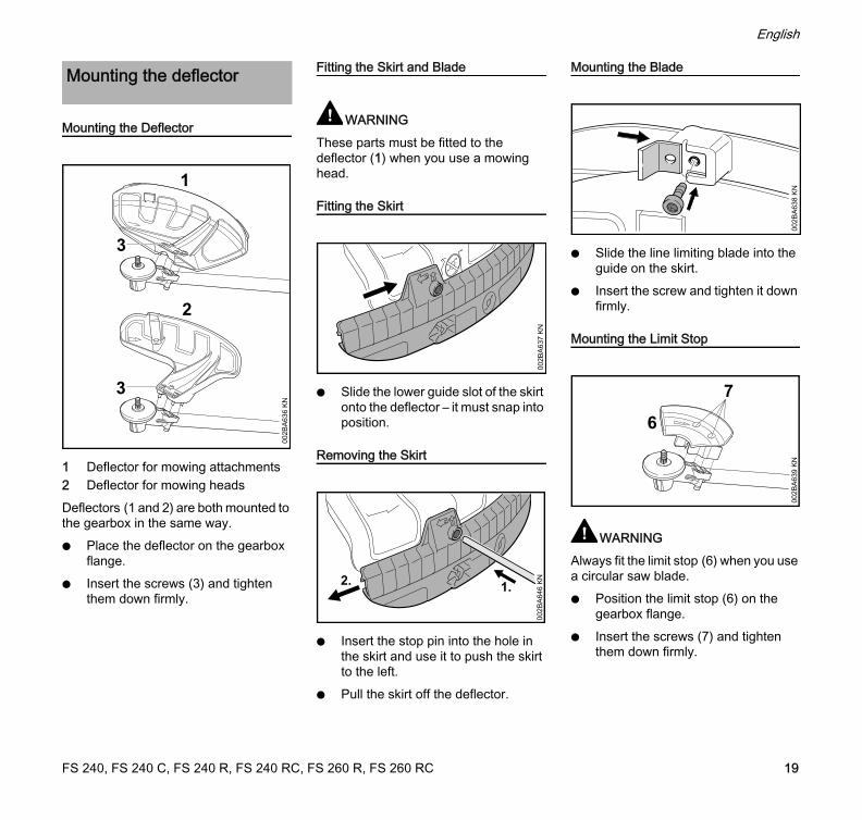
Polymer Version
For position of carrying ring see "Main Parts".N Push the carrying ring (1) over the
drive tube.N Insert the M5 nut in the hex recess
in the carrying ring.N Fit the M5x14 screw.N Line up the carrying ring.N Tighten down the screw firmly.
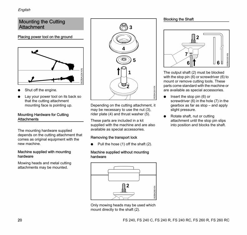
It may be necessary to correct the adjustment of the throttle cable after assembling the machine or after a prolonged period of operation.Adjust the throttle cable only when the unit is completely and properly assembled.
N Set the throttle trigger to the full throttle position.
N Carefully rotate the screw in the throttle trigger in the direction of the arrow until you feel initial resistance. Then rotate it another half turn in the same direction.
4
002B
A57
0 K
N
A
Fitting the Carrying Ring
1
002B
A52
9 K
N
Adjusting the Throttle Cable
002B
A65
5 K
N
FS 240, FS 240 C, FS 240 R, FS 240 RC, FS 260 R, FS 260 RC18
English
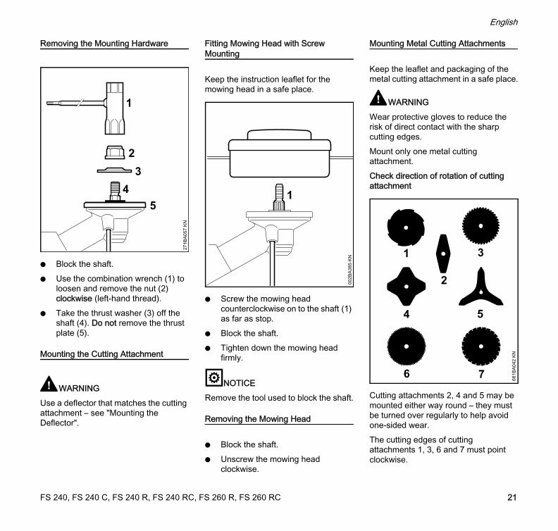
Mounting the Deflector
1 Deflector for mowing attachments2 Deflector for mowing headsDeflectors (1 and 2) are both mounted to the gearbox in the same way.N Place the deflector on the gearbox
flange.N Insert the screws (3) and tighten
them down firmly.
Fitting the Skirt and Blade
WARNINGThese parts must be fitted to the deflector (1) when you use a mowing head.
Fitting the Skirt
N Slide the lower guide slot of the skirt onto the deflector – it must snap into position.
Removing the Skirt
N Insert the stop pin into the hole in the skirt and use it to push the skirt to the left.
N Pull the skirt off the deflector.
Mounting the Blade
N Slide the line limiting blade into the guide on the skirt.
N Insert the screw and tighten it down firmly.
Mounting the Limit Stop
WARNINGAlways fit the limit stop (6) when you use a circular saw blade.N Position the limit stop (6) on the
gearbox flange.N Insert the screws (7) and tighten
them down firmly.
Mounting the deflector
002B
A63
6 K
N
2
1
3
3
002B
A63
7 K
N
1.2.
002B
A64
6 K
N
002B
A63
8 K
N
7
002B
A63
9 K
N
6
FS 240, FS 240 C, FS 240 R, FS 240 RC, FS 260 R, FS 260 RC 19
English
Placing power tool on the ground
N Shut off the engine.N Lay your power tool on its back so
that the cutting attachment mounting face is pointing up.
Mounting Hardware for Cutting Attachments
The mounting hardware supplied depends on the cutting attachment that comes as original equipment with the new machine.
Machine supplied with mounting hardware
Mowing heads and metal cutting attachments may be mounted.
Depending on the cutting attachment, it may be necessary to use the nut (3), rider plate (4) and thrust washer (5).These parts are included in a kit supplied with the machine and are also available as special accessories.
Removing the transport lock
N Pull the hose (1) off the shaft (2).
Machine supplied without mounting hardware
Only mowing heads may be used which mount directly to the shaft (2).
Blocking the Shaft
The output shaft (2) must be blocked with the stop pin (6) or screwdriver (6) to mount or remove cutting tools. These parts come standard with the machine or are available as special accessories.N Insert the stop pin (6) or
screwdriver (6) in the hole (7) in the gearbox as far as stop – and apply slight pressure.
N Rotate shaft, nut or cutting attachment until the stop pin slips into position and blocks the shaft.
Mounting the Cutting Attachment
002B
A10
4 K
N
2
002B
A16
4 K
N
1
3
4
5
2
002B
A26
6 K
N
6
7
2
002B
A33
0 K
N
6
FS 240, FS 240 C, FS 240 R, FS 240 RC, FS 260 R, FS 260 RC20
English
Removing the Mounting Hardware
N Block the shaft.N Use the combination wrench (1) to
loosen and remove the nut (2) clockwise (left-hand thread).
N Take the thrust washer (3) off the shaft (4). Do not remove the thrust plate (5).
Mounting the Cutting Attachment
WARNINGUse a deflector that matches the cutting attachment – see "Mounting the Deflector".
Fitting Mowing Head with Screw Mounting
Keep the instruction leaflet for the mowing head in a safe place.
N Screw the mowing head counterclockwise on to the shaft (1) as far as stop.
N Block the shaft.N Tighten down the mowing head
firmly.
NOTICERemove the tool used to block the shaft.
Removing the Mowing Head
N Block the shaft.N Unscrew the mowing head
clockwise.
Mounting Metal Cutting Attachments
Keep the leaflet and packaging of the metal cutting attachment in a safe place.
WARNINGWear protective gloves to reduce the risk of direct contact with the sharp cutting edges.Mount only one metal cutting attachment.Check direction of rotation of cutting attachment
Cutting attachments 2, 4 and 5 may be mounted either way round – they must be turned over regularly to help avoid one-sided wear.The cutting edges of cutting attachments 1, 3, 6 and 7 must point clockwise.
34
2
271B
A05
7 K
N
1
51
002B
A38
5 K
N 31
4
6 7
5
681B
A04
2 K
N
2
FS 240, FS 240 C, FS 240 R, FS 240 RC, FS 260 R, FS 260 RC 21
English
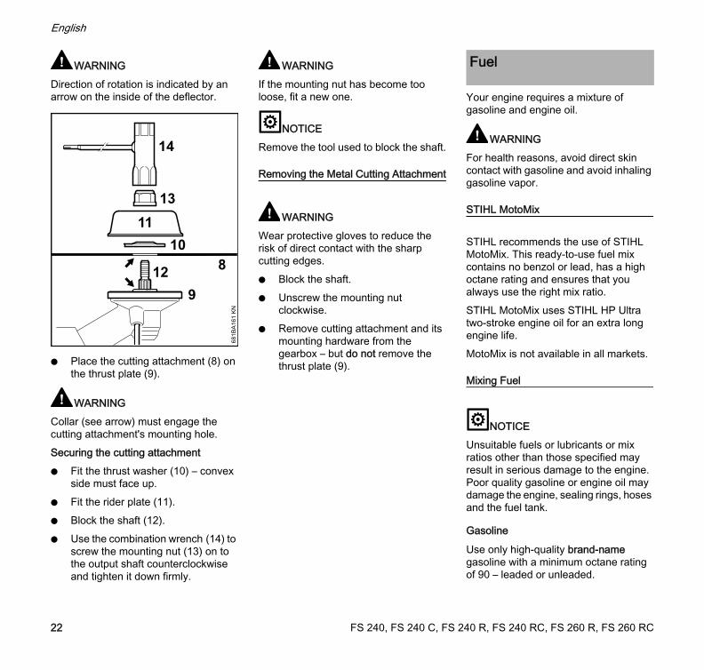
WARNINGDirection of rotation is indicated by an arrow on the inside of the deflector.
N Place the cutting attachment (8) on the thrust plate (9).
WARNINGCollar (see arrow) must engage the cutting attachment's mounting hole.Securing the cutting attachmentN Fit the thrust washer (10) – convex
side must face up.N Fit the rider plate (11).N Block the shaft (12).N Use the combination wrench (14) to
screw the mounting nut (13) on to the output shaft counterclockwise and tighten it down firmly.
WARNINGIf the mounting nut has become too loose, fit a new one.
NOTICERemove the tool used to block the shaft.
Removing the Metal Cutting Attachment
WARNINGWear protective gloves to reduce the risk of direct contact with the sharp cutting edges.N Block the shaft.N Unscrew the mounting nut
clockwise.N Remove cutting attachment and its
mounting hardware from the gearbox – but do not remove the thrust plate (9).
Your engine requires a mixture of gasoline and engine oil.
WARNINGFor health reasons, avoid direct skin contact with gasoline and avoid inhaling gasoline vapor.
STIHL MotoMix
STIHL recommends the use of STIHL MotoMix. This ready-to-use fuel mix contains no benzol or lead, has a high octane rating and ensures that you always use the right mix ratio.STIHL MotoMix uses STIHL HP Ultra two-stroke engine oil for an extra long engine life. MotoMix is not available in all markets.
Mixing Fuel
NOTICEUnsuitable fuels or lubricants or mix ratios other than those specified may result in serious damage to the engine. Poor quality gasoline or engine oil may damage the engine, sealing rings, hoses and the fuel tank.
Gasoline
Use only high-quality brand-name gasoline with a minimum octane rating of 90 – leaded or unleaded.
108
9
11
12
13
14
681B
A16
1 K
N
Fuel
FS 240, FS 240 C, FS 240 R, FS 240 RC, FS 260 R, FS 260 RC22
English
If your machine is equipped with a catalytic converter, you must use unleaded gasoline.
NOTICEA few tankfuls of leaded gasoline will greatly reduce the efficiency of the catalytic converter.Gasoline with an ethanol content of more than 10% can cause running problems in engines with a manually adjustable carburetor and should not be used in such engines.Engines equipped with M-Tronic deliver full power when run on gasoline with an ethanol content of up to 25% (E25).
Engine oil
Use only high-quality two-stroke engine oil – preferably STIHL HP, HP Super or HP Ultra, which are specially formulated for use in STIHL engines. HP Ultra guarantees high performance and a long engine life.These engine oils are not available in all markets.Use only STIHL 50:1 two-stroke engine oil for the fuel mix in models with a catalytic converter.
Mix Ratio
STIHL 50:1 two-stroke engine oil: 50 parts gasoline to 1 part oil
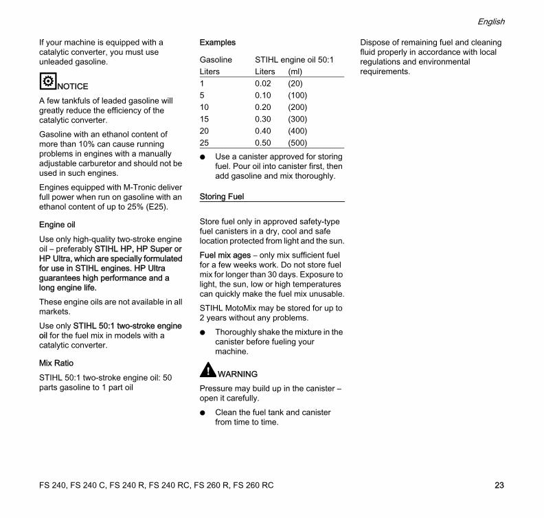
Examples
N Use a canister approved for storing fuel. Pour oil into canister first, then add gasoline and mix thoroughly.
Storing Fuel
Store fuel only in approved safety-type fuel canisters in a dry, cool and safe location protected from light and the sun.Fuel mix ages – only mix sufficient fuel for a few weeks work. Do not store fuel mix for longer than 30 days. Exposure to light, the sun, low or high temperatures can quickly make the fuel mix unusable.STIHL MotoMix may be stored for up to 2 years without any problems.N Thoroughly shake the mixture in the
canister before fueling your machine.
WARNINGPressure may build up in the canister – open it carefully.N Clean the fuel tank and canister
from time to time.
Dispose of remaining fuel and cleaning fluid properly in accordance with local regulations and environmental requirements.
Gasoline STIHL engine oil 50:1 Liters Liters (ml)1 0.02 (20)5 0.10 (100)10 0.20 (200)15 0.30 (300)20 0.40 (400)25 0.50 (500)
FS 240, FS 240 C, FS 240 R, FS 240 RC, FS 260 R, FS 260 RC 23
English
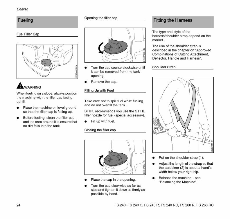
Fuel Filler Cap
WARNINGWhen fueling on a slope, always position the machine with the filler cap facing uphill.N Place the machine on level ground
so that the filler cap is facing up.N Before fueling, clean the filler cap
and the area around it to ensure that no dirt falls into the tank.
Opening the filler cap
N Turn the cap counterclockwise until it can be removed from the tank opening.
N Remove the cap.
Filling Up with Fuel
Take care not to spill fuel while fueling and do not overfill the tank.STIHL recommends you use the STIHL filler nozzle for fuel (special accessory).N Fill up with fuel.
Closing the filler cap
N Place the cap in the opening.N Turn the cap clockwise as far as
stop and tighten it down as firmly as possible by hand.
The type and style of the harness/shoulder strap depend on the market.The use of the shoulder strap is described in the chapter on "Approved Combinations of Cutting Attachment, Deflector, Handle and Harness".
Shoulder Strap
N Put on the shoulder strap (1).N Adjust the length of the strap so that
the carabiner (2) is about a hand’s width below your right hip.
N Balance the machine – see "Balancing the Machine".
Fueling
2709
BA
025
KN
2709
BA
003
KN
2709
BA
004
KN
Fitting the Harness
1
002B
A44
1 K
N
2
FS 240, FS 240 C, FS 240 R, FS 240 RC, FS 260 R, FS 260 RC24
English
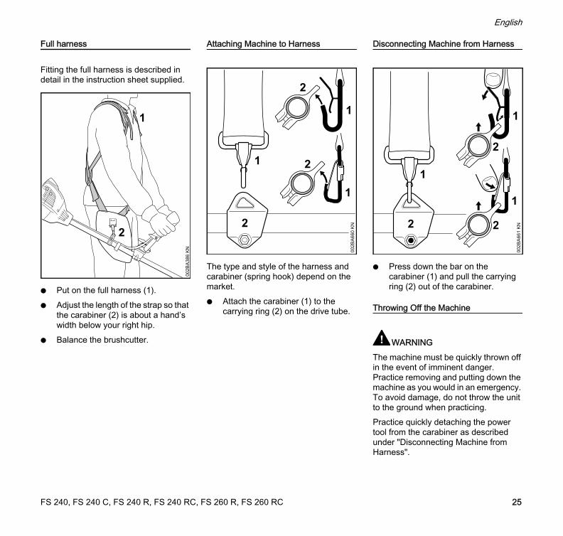
Full harness
Fitting the full harness is described in detail in the instruction sheet supplied.
N Put on the full harness (1).N Adjust the length of the strap so that
the carabiner (2) is about a hand’s width below your right hip.
N Balance the brushcutter.
Attaching Machine to Harness
The type and style of the harness and carabiner (spring hook) depend on the market.N Attach the carabiner (1) to the
carrying ring (2) on the drive tube.
Disconnecting Machine from Harness
N Press down the bar on the carabiner (1) and pull the carrying ring (2) out of the carabiner.
Throwing Off the Machine
WARNINGThe machine must be quickly thrown off in the event of imminent danger. Practice removing and putting down the machine as you would in an emergency. To avoid damage, do not throw the unit to the ground when practicing.Practice quickly detaching the power tool from the carabiner as described under "Disconnecting Machine from Harness".
002B
A38
6 K
N
1
2
1
002B
A66
0 K
N2
1
1
2
2
002B
A66
1 K
N
2
1
1
1
22
FS 240, FS 240 C, FS 240 R, FS 240 RC, FS 260 R, FS 260 RC 25
English
If you are using a shoulder strap: Practice slipping the strap off your shoulder.If you are using a full harness: Practice quickly opening the locking plate and slipping the harness straps off your shoulders.
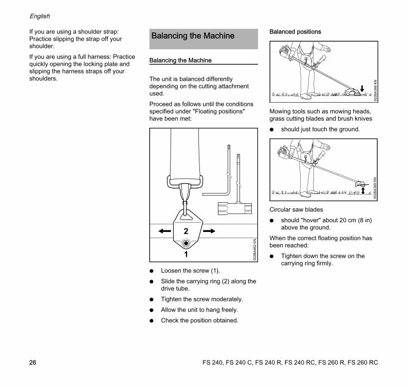
Balancing the Machine
The unit is balanced differently depending on the cutting attachment used.Proceed as follows until the conditions specified under "Floating positions" have been met:
N Loosen the screw (1).N Slide the carrying ring (2) along the
drive tube.N Tighten the screw moderately.N Allow the unit to hang freely.N Check the position obtained.
Balanced positions
Mowing tools such as mowing heads, grass cutting blades and brush knivesN should just touch the ground.
Circular saw bladesN should "hover" about 20 cm (8 in)
above the ground.When the correct floating position has been reached:N Tighten down the screw on the
carrying ring firmly.
Balancing the Machine
002B
A66
2 K
N1
2
002B
A38
8 K
N00
2BA
389
KN
FS 240, FS 240 C, FS 240 R, FS 240 RC, FS 260 R, FS 260 RC26
English
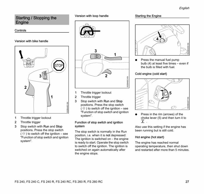
Controls
Version with bike handle
1 Throttle trigger lockout2 Throttle trigger3 Stop switch with Run and Stop
positions. Press the stop switch (…) to switch off the ignition – see "Function of stop switch and ignition system".
Version with loop handle
1 Throttle trigger lockout2 Throttle trigger3 Stop switch with Run and Stop
positions. Press the stop switch (…) to switch off the ignition – see "Function of stop switch and ignition system".
Function of stop switch and ignition system
The stop switch is normally in the Run position, i.e. when it is not depressed: The ignition is switched on – the engine is ready to start. Operate the stop switch to switch off the ignition. The ignition is switched on again automatically after the engine stops.
Starting the Engine
N Press the manual fuel pump bulb (4) at least five times – even if the bulb is filled with fuel.
Cold engine (cold start)
N Press in the rim (arrows) of the choke lever (5) and then turn it to g .
Also use this setting if the engine has been running but is still cold.
Hot engine (hot start)
The engine has reached normal operating temperature, then shut down and restarted after more than 5 minutes.
Starting / Stopping the Engine
1
002B
A48
3 K
N
2
3
1
002B
A66
3 K
N2
3
4
9926
BA
006
KN
5
9926
BA
007
KN
5
FS 240, FS 240 C, FS 240 R, FS 240 RC, FS 260 R, FS 260 RC 27
English
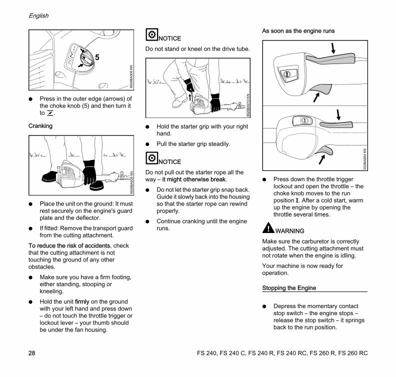
N Press in the outer edge (arrows) of the choke knob (5) and then turn it to <.
Cranking
N Place the unit on the ground: It must rest securely on the engine's guard plate and the deflector.
N If fitted: Remove the transport guard from the cutting attachment.
To reduce the risk of accidents, check that the cutting attachment is not touching the ground of any other obstacles.N Make sure you have a firm footing,
either standing, stooping or kneeling.
N Hold the unit firmly on the ground with your left hand and press down – do not touch the throttle trigger or lockout lever – your thumb should be under the fan housing.
NOTICEDo not stand or kneel on the drive tube.
N Hold the starter grip with your right hand.
N Pull the starter grip steadily.
NOTICEDo not pull out the starter rope all the way – it might otherwise break.N Do not let the starter grip snap back.
Guide it slowly back into the housing so that the starter rope can rewind properly.
N Continue cranking until the engine runs.
As soon as the engine runs
N Press down the throttle trigger lockout and open the throttle – the choke knob moves to the run position F. After a cold start, warm up the engine by opening the throttle several times.
WARNINGMake sure the carburetor is correctly adjusted. The cutting attachment must not rotate when the engine is idling.Your machine is now ready for operation.
Stopping the Engine
N Depress the momentary contact stop switch – the engine stops – release the stop switch – it springs back to the run position.
9926
BA
008
KN
5
9926
BA
009
KN
9926
BA
010
KN
002B
A66
4 K
N
FS 240, FS 240 C, FS 240 R, FS 240 RC, FS 260 R, FS 260 RC28
English
Other Hints on Starting
At very low outside temperaturesN Set the engine to winter operation if
necessary, see "Winter Operation".N If your machine is very cold (frost or
ice on machine), start the engine and keep it at a high idle speed (cutting attachment rotates) until it reaches normal operating temperature.
Engine stalls in cold start position g or under accelerationN Move the choke lever to < and
continue cranking until the engine runs.
Engine does not start in hot start position <
N Move the choke lever to g and continue cranking until the engine runs.
If the engine does not startN Check that all settings are correct.N Check that there is fuel in the tank
and refuel if necessary.N Check that the spark plug boot is
properly connected.N Repeat the starting procedure.Engine is floodedN Move the choke lever to < and
continue cranking until the engine runs.
Fuel tank run until completely dry
Recommendation: Carry out the following steps irrespective of the engine's operating condition before the tank was run dry.N Set the choke lever to g.N Go to section on "Starting the
Engine" and re-start the engine as described for a cold engine.
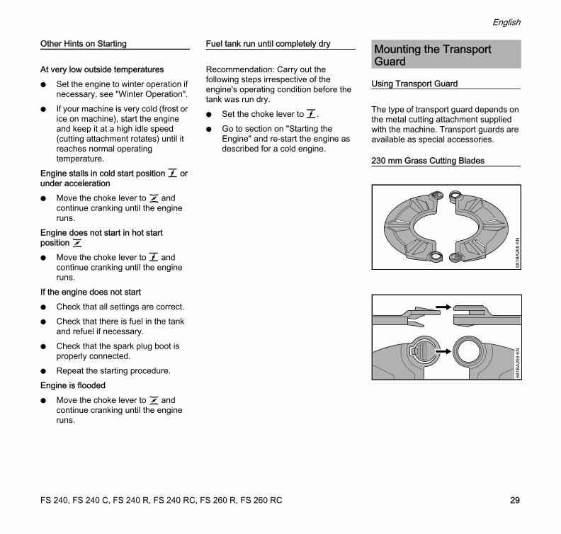
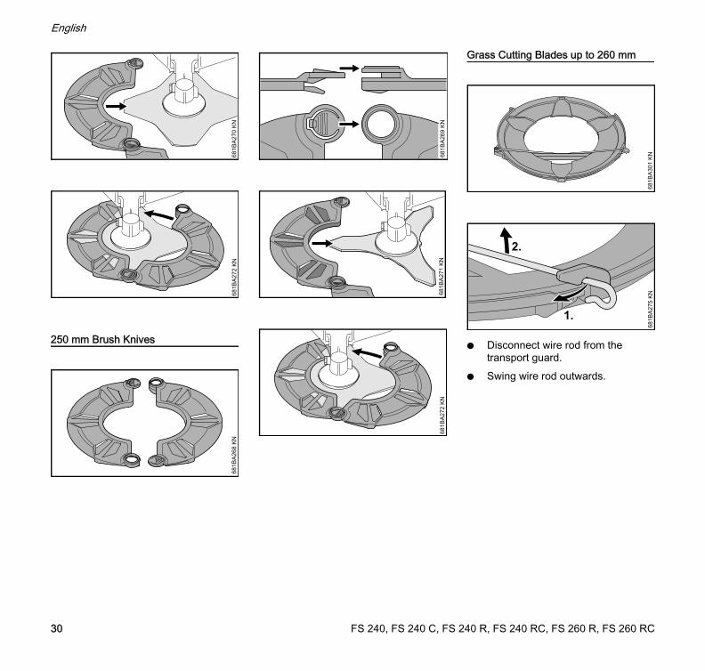
Using Transport Guard
The type of transport guard depends on the metal cutting attachment supplied with the machine. Transport guards are available as special accessories.
230 mm Grass Cutting Blades
Mounting the Transport Guard
681B
A26
8 K
N68
1BA
269
KN
FS 240, FS 240 C, FS 240 R, FS 240 RC, FS 260 R, FS 260 RC 29
English
250 mm Brush Knives
Grass Cutting Blades up to 260 mm
N Disconnect wire rod from the transport guard.
N Swing wire rod outwards.
681B
A27
0 K
N68
1BA
272
KN
681B
A26
8 K
N
681B
A26
9 K
N68
1BA
271
KN
681B
A27
2 K
N
681B
A30
1 K
N68
1BA
275
KN
1.
2.
FS 240, FS 240 C, FS 240 R, FS 240 RC, FS 260 R, FS 260 RC30
English
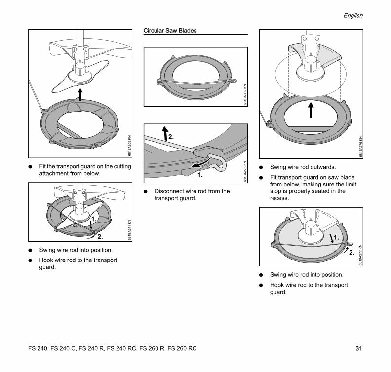
N Fit the transport guard on the cutting attachment from below.
N Swing wire rod into position.N Hook wire rod to the transport
guard.
Circular Saw Blades
N Disconnect wire rod from the transport guard.
N Swing wire rod outwards.N Fit transport guard on saw blade
from below, making sure the limit stop is properly seated in the recess.
N Swing wire rod into position.N Hook wire rod to the transport
guard.
681B
A30
5 K
N
2. 681B
A31
1 K
N
681B
A30
2 K
N68
1BA
275
KN
1.
2.
681B
A27
6 K
N68
1BA
277
KN
2.
FS 240, FS 240 C, FS 240 R, FS 240 RC, FS 260 R, FS 260 RC 31
English
During break-in period
A factory-new machine should not be run at high revs (full throttle off load) for the first three tank fillings. This avoids unnecessary high loads during the break-in period. As all moving parts have to bed in during the break-in period, the frictional resistances in the engine are greater during this period. The engine develops its maximum power after about 5 to 15 tank fillings.
During Operation
After a long period of full throttle operation, allow the engine to run for a short while at idle speed so that engine heat can be dissipated by the flow of cooling air. This protects engine-mounted components (ignition, carburetor) from thermal overload.
After Finishing Work
Storing for a short period: Wait for the engine to cool down. Empty the fuel tank and keep the machine in a dry place, well away from sources of ignition, until you need it again. For longer out-of-service periods – see "Storing the Machine".
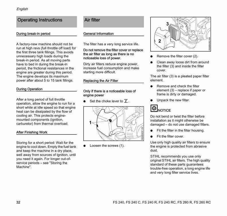
General Information
The filter has a very long service life. Do not remove the filter cover or replace the air filter as long as there is no noticeable loss of power.Dirty air filters reduce engine power, increase fuel consumption and make starting more difficult.
Replacing the Air Filter
Only if there is a noticeable loss of engine powerN Set the choke lever to g.
N Loosen the screws (1).
N Remove the filter cover (2).N Clean away loose dirt from around
the filter (3) and inside the filter cover.
The air filter (3) is a pleated paper filter element.N Remove and check the filter
element (3) – replace if paper or frame is dirty or damaged.
N Unpack the new filter.
NOTICEDo not bend or twist the filter before installation as it might otherwise be damaged – do not use damaged filters.N Fit the filter in the filter housing.N Fit the filter cover.Use only high quality air filters to ensure the engine is protected from abrasive dust.STIHL recommends you use only original STIHL air filters. The high quality standard of these parts guarantees trouble-free operation, a long engine life and very long filter service lives.
Operating Instructions Air filter
9926
BA
061
KN
1
3
9926
BA
062
KN
2
FS 240, FS 240 C, FS 240 R, FS 240 RC, FS 260 R, FS 260 RC32
English
Filter Element for Winter Operation
Maintenance and care of the special filter element for winter operation are described in the chapter on "Winter Operation".
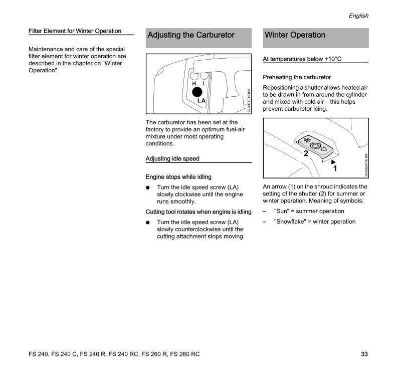
The carburetor has been set at the factory to provide an optimum fuel-air mixture under most operating conditions.
Adjusting idle speed
Engine stops while idlingN Turn the idle speed screw (LA)
slowly clockwise until the engine runs smoothly.
Cutting tool rotates when engine is idlingN Turn the idle speed screw (LA)
slowly counterclockwise until the cutting attachment stops moving.
At temperatures below +10°C
Preheating the carburetorRepositioning a shutter allows heated air to be drawn in from around the cylinder and mixed with cold air – this helps prevent carburetor icing.
An arrow (1) on the shroud indicates the setting of the shutter (2) for summer or winter operation. Meaning of symbols:– "Sun" = summer operation– "Snowflake" = winter operation
Adjusting the Carburetor
9926
BA
015
KN
H L
LA
Winter Operation
2
1
9926
BA
016
KN
FS 240, FS 240 C, FS 240 R, FS 240 RC, FS 260 R, FS 260 RC 33
English
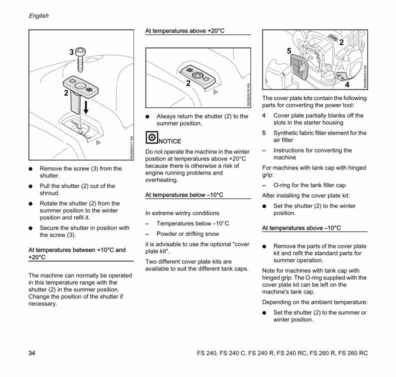
N Remove the screw (3) from the shutter.
N Pull the shutter (2) out of the shroud.
N Rotate the shutter (2) from the summer position to the winter position and refit it.
N Secure the shutter in position with the screw (3).
At temperatures between +10°C and +20°C
The machine can normally be operated in this temperature range with the shutter (2) in the summer position. Change the position of the shutter if necessary.
At temperatures above +20°C
N Always return the shutter (2) to the summer position.
NOTICEDo not operate the machine in the winter position at temperatures above +20°C because there is otherwise a risk of engine running problems and overheating.
At temperatures below –10°C
In extreme wintry conditions– Temperatures below –10°C– Powder or drifting snowit is advisable to use the optional "cover plate kit".Two different cover plate kits are available to suit the different tank caps.
The cover plate kits contain the following parts for converting the power tool:4 Cover plate partially blanks off the
slots in the starter housing5 Synthetic fabric filter element for the
air filter– Instructions for converting the
machineFor machines with tank cap with hinged grip:– O-ring for the tank filler capAfter installing the cover plate kit:N Set the shutter (2) to the winter
position.
At temperatures above –10°C
N Remove the parts of the cover plate kit and refit the standard parts for summer operation.
Note for machines with tank cap with hinged grip: The O-ring supplied with the cover plate kit can be left on the machine's tank cap.Depending on the ambient temperature:N Set the shutter (2) to the summer or
winter position.
2
9926
BA
017
KN
3
2
9926
BA
018
KN 4
5
9926
BA
063
KN
2
FS 240, FS 240 C, FS 240 R, FS 240 RC, FS 260 R, FS 260 RC34
English
Cleaning the Air Filters
N Loosen filter cover mounting screws.
N Remove the filter cover.N Clean away loose dirt from around
the filter (5) and inside the filter cover.
N Knock the filter (5) out on the palm of your hand or blow it clear with compressed air from the inside outwards.
In case of stubborn dirt or sticky filter fabric:N Wash the filter in a clean, non-
flammable solution (e.g. warm soapy water) and then dry.
Always replace a damaged filter.
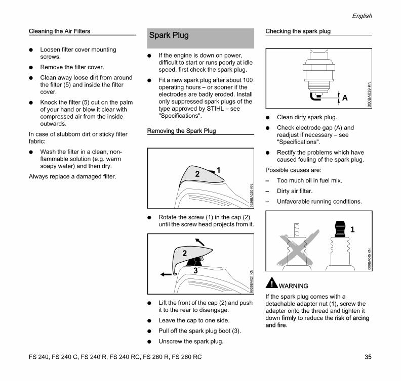
N If the engine is down on power, difficult to start or runs poorly at idle speed, first check the spark plug.
N Fit a new spark plug after about 100 operating hours – or sooner if the electrodes are badly eroded. Install only suppressed spark plugs of the type approved by STIHL – see "Specifications".
Removing the Spark Plug
N Rotate the screw (1) in the cap (2) until the screw head projects from it.
N Lift the front of the cap (2) and push it to the rear to disengage.
N Leave the cap to one side.N Pull off the spark plug boot (3).N Unscrew the spark plug.
Checking the spark plug
N Clean dirty spark plug.N Check electrode gap (A) and
readjust if necessary – see "Specifications".
N Rectify the problems which have caused fouling of the spark plug.
Possible causes are:– Too much oil in fuel mix.– Dirty air filter.– Unfavorable running conditions.
WARNINGIf the spark plug comes with a detachable adapter nut (1), screw the adapter onto the thread and tighten it down firmly to reduce the risk of arcing and fire.
Spark Plug
1
9926
BA
020
KN
3
9926
BA
021
KN
000B
A03
9 K
N
A
1
000B
A04
5 K
N
FS 240, FS 240 C, FS 240 R, FS 240 RC, FS 260 R, FS 260 RC 35
English
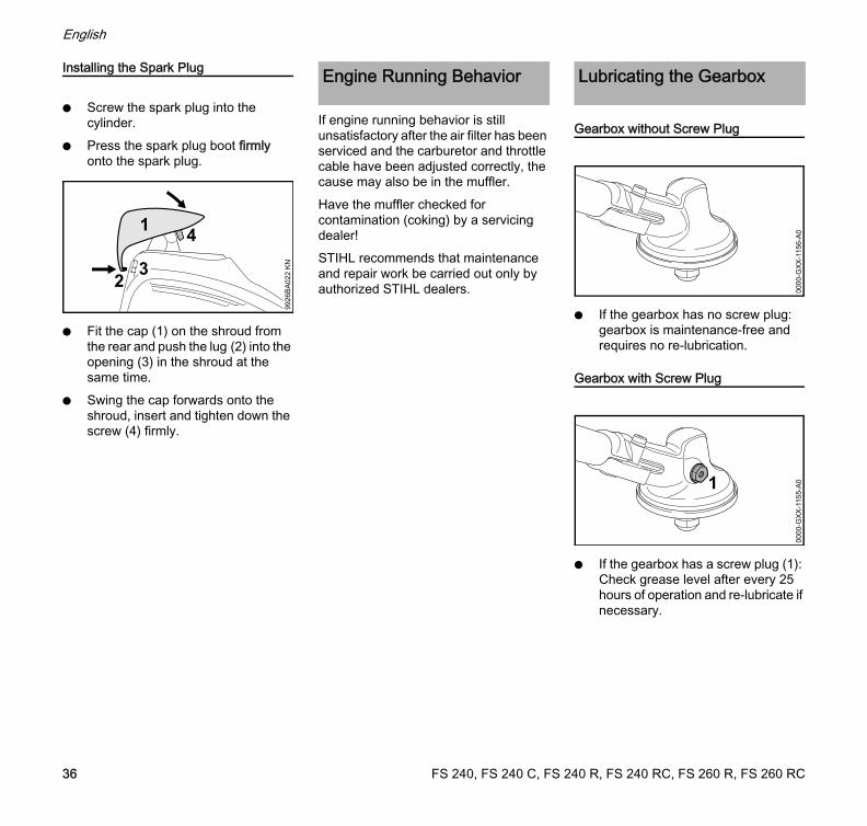
Installing the Spark Plug
N Screw the spark plug into the cylinder.
N Press the spark plug boot firmly onto the spark plug.
N Fit the cap (1) on the shroud from the rear and push the lug (2) into the opening (3) in the shroud at the same time.
N Swing the cap forwards onto the shroud, insert and tighten down the screw (4) firmly.
If engine running behavior is still unsatisfactory after the air filter has been serviced and the carburetor and throttle cable have been adjusted correctly, the cause may also be in the muffler.Have the muffler checked for contamination (coking) by a servicing dealer!STIHL recommends that maintenance and repair work be carried out only by authorized STIHL dealers.
Gearbox without Screw Plug
N If the gearbox has no screw plug: gearbox is maintenance-free and requires no re-lubrication.
Gearbox with Screw Plug
N If the gearbox has a screw plug (1): Check grease level after every 25 hours of operation and re-lubricate if necessary.
4
32
9926
BA
022
KN
Engine Running Behavior Lubricating the Gearbox
0000
-GX
X-1
156-
A0
1
0000
-GX
X-1
155-
A0
FS 240, FS 240 C, FS 240 R, FS 240 RC, FS 260 R, FS 260 RC36
English
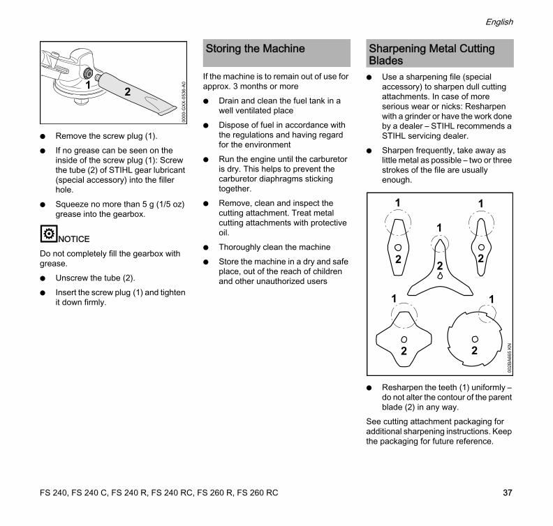
N Remove the screw plug (1).N If no grease can be seen on the
inside of the screw plug (1): Screw the tube (2) of STIHL gear lubricant (special accessory) into the filler hole.
N Squeeze no more than 5 g (1/5 oz) grease into the gearbox.
NOTICEDo not completely fill the gearbox with grease.N Unscrew the tube (2).N Insert the screw plug (1) and tighten
it down firmly.
If the machine is to remain out of use for approx. 3 months or moreN Drain and clean the fuel tank in a
well ventilated placeN Dispose of fuel in accordance with
the regulations and having regard for the environment
N Run the engine until the carburetor is dry. This helps to prevent the carburetor diaphragms sticking together.
N Remove, clean and inspect the cutting attachment. Treat metal cutting attachments with protective oil.
N Thoroughly clean the machineN Store the machine in a dry and safe
place, out of the reach of children and other unauthorized users
N Use a sharpening file (special accessory) to sharpen dull cutting attachments. In case of more serious wear or nicks: Resharpen with a grinder or have the work done by a dealer – STIHL recommends a STIHL servicing dealer.
N Sharpen frequently, take away as little metal as possible – two or three strokes of the file are usually enough.
N Resharpen the teeth (1) uniformly – do not alter the contour of the parent blade (2) in any way.
See cutting attachment packaging for additional sharpening instructions. Keep the packaging for future reference.
1
0000
-GX
X-0
536-
A0
Storing the Machine Sharpening Metal Cutting Blades
002B
A66
5 K
N
1
22
1
22
1
2
1
1
FS 240, FS 240 C, FS 240 R, FS 240 RC, FS 260 R, FS 260 RC 37
English
Balancing
N After resharpening about 5 times, check the cutting attachment for out-of-balance on a STIHL balancer (special accessory) or have it checked by a dealer and re-balanced as necessary – STIHL recommends a STIHL servicing dealer.
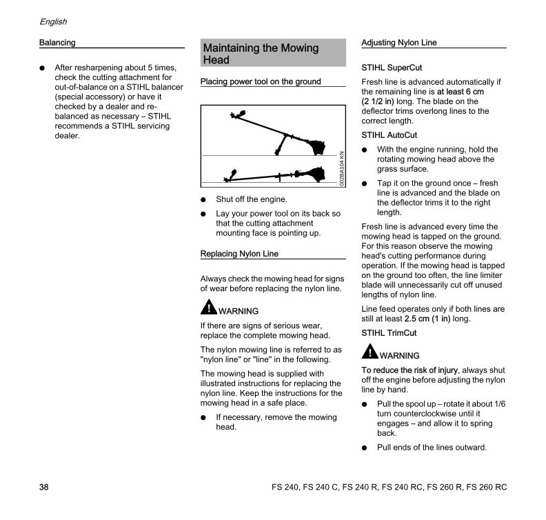
Placing power tool on the ground
N Shut off the engine.N Lay your power tool on its back so
that the cutting attachment mounting face is pointing up.
Replacing Nylon Line
Always check the mowing head for signs of wear before replacing the nylon line.
WARNINGIf there are signs of serious wear, replace the complete mowing head.The nylon mowing line is referred to as "nylon line" or "line" in the following.The mowing head is supplied with illustrated instructions for replacing the nylon line. Keep the instructions for the mowing head in a safe place.N If necessary, remove the mowing
head.
Adjusting Nylon Line
STIHL SuperCutFresh line is advanced automatically if the remaining line is at least 6 cm (2 1/2 in) long. The blade on the deflector trims overlong lines to the correct length.STIHL AutoCutN With the engine running, hold the
rotating mowing head above the grass surface.
N Tap it on the ground once – fresh line is advanced and the blade on the deflector trims it to the right length.
Fresh line is advanced every time the mowing head is tapped on the ground. For this reason observe the mowing head's cutting performance during operation. If the mowing head is tapped on the ground too often, the line limiter blade will unnecessarily cut off unused lengths of nylon line.Line feed operates only if both lines are still at least 2.5 cm (1 in) long.STIHL TrimCut
WARNINGTo reduce the risk of injury, always shut off the engine before adjusting the nylon line by hand.N Pull the spool up – rotate it about 1/6
turn counterclockwise until it engages – and allow it to spring back.
N Pull ends of the lines outward.
Maintaining the Mowing Head
002B
A10
4 K
N
FS 240, FS 240 C, FS 240 R, FS 240 RC, FS 260 R, FS 260 RC38
English
Repeat the above procedure as necessary until both lines reach the limiter blade on the deflector.Rotating the spool from one stop to the next advances about 4 cm (1 1/2 in) of fresh line.
Replacing Nylon Line
STIHL PolyCutA length of nylon line can be fitted to the PolyCut in place of the cutting blades.STIHL DuroCut, STIHL PolyCut
WARNINGTo reduce the risk of injury, always shut off the engine before refilling the mowing head.N Fit nylon line in the mowing head as
described in the instructions supplied.
Replacing Cutting Blades
STIHL PolyCut
Always check the mowing head for signs of wear before installing new cutting blades.
WARNINGIf there are signs of serious wear, replace the complete mowing head.The thermoplastic cutting blades are referred to as "blades" in the following.
The mowing head is supplied with illustrated instructions for replacing the blades. Keep the instructions for the mowing head in a safe place.
WARNINGTo reduce the risk of injury, always shut off the engine before installing the blades.N Remove the mowing head.N Replace blades as shown in the
illustrated instructions.N Mount the mowing head on the
machine.
FS 240, FS 240 C, FS 240 R, FS 240 RC, FS 260 R, FS 260 RC 39
English
Maintenance and Care
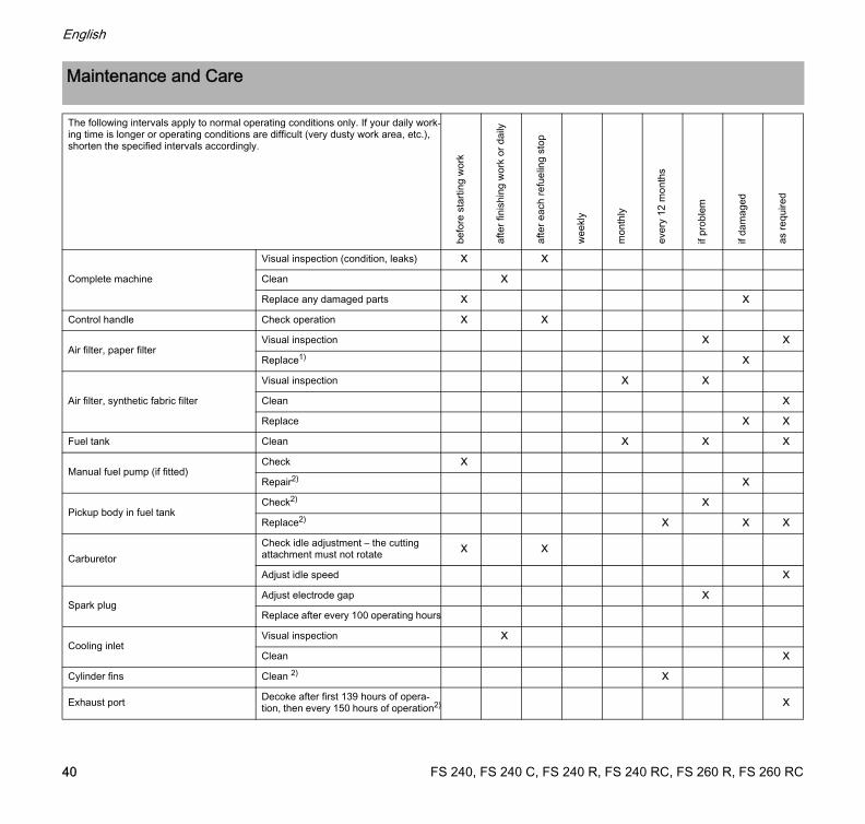
The following intervals apply to normal operating conditions only. If your daily work-ing time is longer or operating conditions are difficult (very dusty work area, etc.), shorten the specified intervals accordingly.
befo
re s
tarti
ng w
ork
afte
r fin
ishi
ng w
ork
or d
aily
afte
r eac
h re
fuel
ing
stop
wee
kly
mon
thly
ever
y 12
mon
ths
if pr
oble
m
if da
mag
ed
as re
quire
d
Complete machine
Visual inspection (condition, leaks) X X
Clean X
Replace any damaged parts X X
Control handle Check operation X X
Air filter, paper filterVisual inspection X X
Replace1) X
Air filter, synthetic fabric filter
Visual inspection X X
Clean X
Replace X X
Fuel tank Clean X X X
Manual fuel pump (if fitted)Check X
Repair2) X
Pickup body in fuel tankCheck2) X
Replace2) X X X
CarburetorCheck idle adjustment – the cutting attachment must not rotate X X
Adjust idle speed X
Spark plugAdjust electrode gap X
Replace after every 100 operating hours
Cooling inletVisual inspection X
Clean X
Cylinder fins Clean 2) X
Exhaust port Decoke after first 139 hours of opera-tion, then every 150 hours of operation2) X
FS 240, FS 240 C, FS 240 R, FS 240 RC, FS 260 R, FS 260 RC40
English
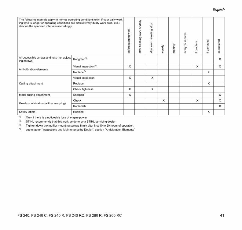
All accessible screws and nuts (not adjust-ing screws) Retighten3) X
Anti-vibration elementsVisual inspection4) X X X
Replace2) X
Cutting attachment
Visual inspection X X
Replace X
Check tightness X X
Metal cutting attachment Sharpen X X
Gearbox lubrication (with screw plug)Check X X X
Replenish X
Safety labels Replace X1) Only if there is a noticeable loss of engine power2) STIHL recommends that this work be done by a STIHL servicing dealer3) Tighten down the muffler mounting screws firmly after first 10 to 20 hours of operation.4) see chapter "Inspections and Maintenance by Dealer", section "Antivibration Elements"
The following intervals apply to normal operating conditions only. If your daily work-ing time is longer or operating conditions are difficult (very dusty work area, etc.), shorten the specified intervals accordingly.
befo
re s
tarti
ng w
ork
afte
r fin
ishi
ng w
ork
or d
aily
afte
r eac
h re
fuel
ing
stop
wee
kly
mon
thly
ever
y 12
mon
ths
if pr
oble
m
if da
mag
ed
as re
quire
d
FS 240, FS 240 C, FS 240 R, FS 240 RC, FS 260 R, FS 260 RC 41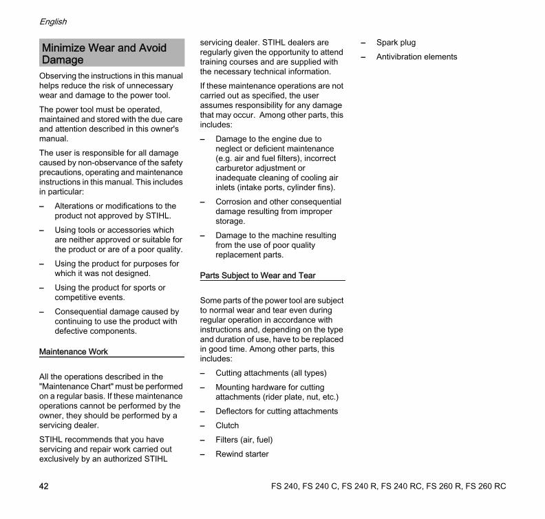
English
Observing the instructions in this manual helps reduce the risk of unnecessary wear and damage to the power tool.The power tool must be operated, maintained and stored with the due care and attention described in this owner's manual.The user is responsible for all damage caused by non-observance of the safety precautions, operating and maintenance instructions in this manual. This includes in particular:– Alterations or modifications to the
product not approved by STIHL.– Using tools or accessories which
are neither approved or suitable for the product or are of a poor quality.
– Using the product for purposes for which it was not designed.
– Using the product for sports or competitive events.
– Consequential damage caused by continuing to use the product with defective components.
Maintenance Work
All the operations described in the "Maintenance Chart" must be performed on a regular basis. If these maintenance operations cannot be performed by the owner, they should be performed by a servicing dealer.STIHL recommends that you have servicing and repair work carried out exclusively by an authorized STIHL
servicing dealer. STIHL dealers are regularly given the opportunity to attend training courses and are supplied with the necessary technical information.If these maintenance operations are not carried out as specified, the user assumes responsibility for any damage that may occur. Among other parts, this includes:– Damage to the engine due to
neglect or deficient maintenance (e.g. air and fuel filters), incorrect carburetor adjustment or inadequate cleaning of cooling air inlets (intake ports, cylinder fins).
– Corrosion and other consequential damage resulting from improper storage.
– Damage to the machine resulting from the use of poor quality replacement parts.
Parts Subject to Wear and Tear
Some parts of the power tool are subject to normal wear and tear even during regular operation in accordance with instructions and, depending on the type and duration of use, have to be replaced in good time. Among other parts, this includes:– Cutting attachments (all types)– Mounting hardware for cutting
attachments (rider plate, nut, etc.)– Deflectors for cutting attachments– Clutch– Filters (air, fuel)– Rewind starter
– Spark plug– Antivibration elements
Minimize Wear and Avoid Damage
FS 240, FS 240 C, FS 240 R, FS 240 RC, FS 260 R, FS 260 RC42

English
1 Tank cap2 Carburetor adjusting screw3 Starter grip4 Shutter (winter operation)5 Spark plug boot with cap6 Muffler7 Guard plate8 Throttle trigger9 Stop switch10 Throttle trigger lockout11 Bike handle (handlebar)12 Handle support13 Wing screw14 Throttle cable retainer15 Carrying ring16 Choke lever17 Manual fuel pump18 Air filter cover19 Fuel tank20 Loop handle21 Barrier bar# Serial number
Main Parts
5
109
108
9
1113
1918
1617
6
4
21
3
12
14
9926
BA
071
KN
#
7
15
21
20
15
8
FS 240, FS 240 C, FS 240 R, FS 240 RC, FS 260 R, FS 260 RC 43
English
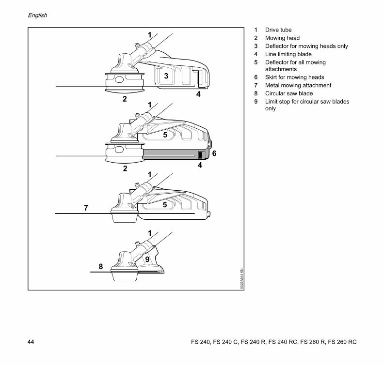
1 Drive tube2 Mowing head3 Deflector for mowing heads only4 Line limiting blade5 Deflector for all mowing
attachments6 Skirt for mowing heads7 Metal mowing attachment8 Circular saw blade9 Limit stop for circular saw blades
only
5
5
8
1
2
64
7
2
3
1
1
9
100
2BA
644
KN
4
FS 240, FS 240 C, FS 240 R, FS 240 RC, FS 260 R, FS 260 RC44
English
Engine
Single cylinder two-stroke engine
FS 240, FS 240 C
FS 240 R, FS 240 RC
FS 260 R, FS 260 RC
Ignition System
Electronic magneto ignition
Fuel System
All position diaphragm carburetor with integral fuel pump
Weight
Overall length
Features
Noise and Vibration Data
For further details on compliance with Vibration Directive 2002/44/EC see www.stihl.com/vib.
Sound pressure level Lp to ISO 22868
Specifications
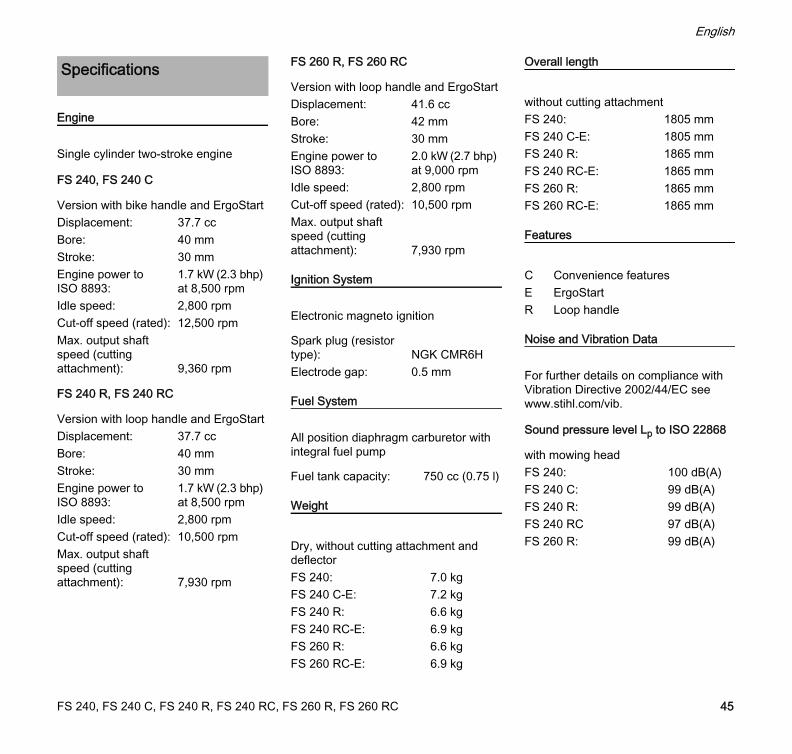
Version with bike handle and ErgoStartDisplacement: 37.7 ccBore: 40 mmStroke: 30 mmEngine power to ISO 8893:
1.7 kW (2.3 bhp) at 8,500 rpm
Idle speed: 2,800 rpmCut-off speed (rated): 12,500 rpmMax. output shaft speed (cutting attachment): 9,360 rpm
Version with loop handle and ErgoStartDisplacement: 37.7 ccBore: 40 mmStroke: 30 mmEngine power to ISO 8893:
1.7 kW (2.3 bhp) at 8,500 rpm
Idle speed: 2,800 rpmCut-off speed (rated): 10,500 rpmMax. output shaft speed (cutting attachment): 7,930 rpm
Version with loop handle and ErgoStartDisplacement: 41.6 ccBore: 42 mmStroke: 30 mmEngine power to ISO 8893:
2.0 kW (2.7 bhp) at 9,000 rpm
Idle speed: 2,800 rpmCut-off speed (rated): 10,500 rpmMax. output shaft speed (cutting attachment): 7,930 rpm
Spark plug (resistor type): NGK CMR6HElectrode gap: 0.5 mm
Fuel tank capacity: 750 cc (0.75 l)
Dry, without cutting attachment and deflectorFS 240: 7.0 kgFS 240 C-E: 7.2 kgFS 240 R: 6.6 kgFS 240 RC-E: 6.9 kgFS 260 R: 6.6 kgFS 260 RC-E: 6.9 kg
without cutting attachmentFS 240: 1805 mmFS 240 C-E: 1805 mmFS 240 R: 1865 mmFS 240 RC-E: 1865 mmFS 260 R: 1865 mmFS 260 RC-E: 1865 mm
C Convenience featuresE ErgoStartR Loop handle
with mowing headFS 240: 100 dB(A)FS 240 C: 99 dB(A)FS 240 R: 99 dB(A)FS 240 RC 97 dB(A)FS 260 R: 99 dB(A)
FS 240, FS 240 C, FS 240 R, FS 240 RC, FS 260 R, FS 260 RC 45
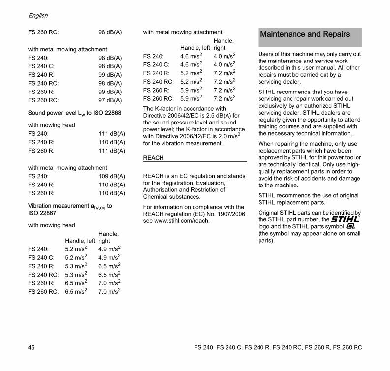
English
Sound power level Lw to ISO 22868
Vibration measurement ahv,eq to ISO 22867
The K-factor in accordance with Directive 2006/42/EC is 2.5 dB(A) for the sound pressure level and sound power level; the K-factor in accordance with Directive 2006/42/EC is 2.0 m/s2 for the vibration measurement.
REACH
REACH is an EC regulation and stands for the Registration, Evaluation, Authorisation and Restriction of Chemical substances.For information on compliance with the REACH regulation (EC) No. 1907/2006 see www.stihl.com/reach.
Users of this machine may only carry out the maintenance and service work described in this user manual. All other repairs must be carried out by a servicing dealer.STIHL recommends that you have servicing and repair work carried out exclusively by an authorized STIHL servicing dealer. STIHL dealers are regularly given the opportunity to attend training courses and are supplied with the necessary technical information.When repairing the machine, only use replacement parts which have been approved by STIHL for this power tool or are technically identical. Only use high-quality replacement parts in order to avoid the risk of accidents and damage to the machine.STIHL recommends the use of original STIHL replacement parts.Original STIHL parts can be identified by the STIHL part number, the { logo and the STIHL parts symbol K (the symbol may appear alone on small parts).
FS 260 RC: 98 dB(A)
with metal mowing attachmentFS 240: 98 dB(A)FS 240 C: 98 dB(A)FS 240 R: 99 dB(A)FS 240 RC: 98 dB(A)FS 260 R: 99 dB(A)FS 260 RC: 97 dB(A)
with mowing headFS 240: 111 dB(A)FS 240 R: 110 dB(A)FS 260 R: 111 dB(A)
with metal mowing attachmentFS 240: 109 dB(A)FS 240 R: 110 dB(A)FS 260 R: 110 dB(A)
with mowing head
Handle, leftHandle, right
FS 240: 5.2 m/s2 4.9 m/s2
FS 240 C: 5.2 m/s2 4.9 m/s2
FS 240 R: 5.3 m/s2 6.5 m/s2
FS 240 RC: 5.3 m/s2 6.5 m/s2
FS 260 R: 6.5 m/s2 7.0 m/s2
FS 260 RC: 6.5 m/s2 7.0 m/s2
with metal mowing attachment
Handle, leftHandle, right
FS 240: 4.6 m/s2 4.0 m/s2
FS 240 C: 4.6 m/s2 4.0 m/s2
FS 240 R: 5.2 m/s2 7.2 m/s2
FS 240 RC: 5.2 m/s2 7.2 m/s2
FS 260 R: 5.9 m/s2 7.2 m/s2
FS 260 RC: 5.9 m/s2 7.2 m/s2
Maintenance and Repairs
FS 240, FS 240 C, FS 240 R, FS 240 RC, FS 260 R, FS 260 RC46
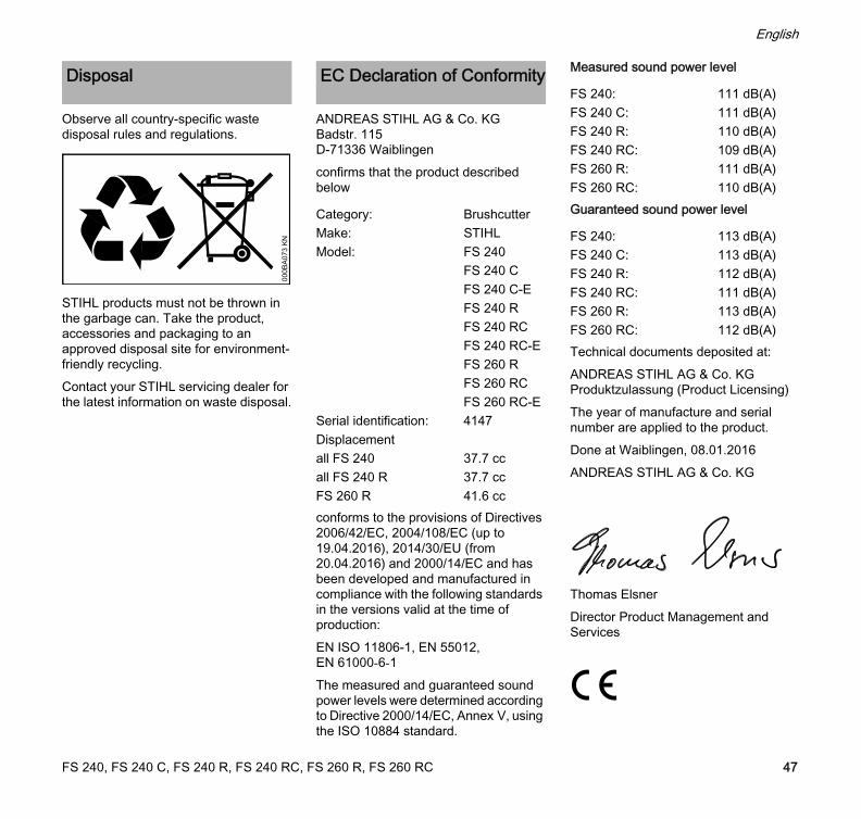
English
Observe all country-specific waste disposal rules and regulations.
STIHL products must not be thrown in the garbage can. Take the product, accessories and packaging to an approved disposal site for environment-friendly recycling.Contact your STIHL servicing dealer for the latest information on waste disposal.
ANDREAS STIHL AG & Co. KGBadstr. 115D-71336 Waiblingenconfirms that the product described below
conforms to the provisions of Directives 2006/42/EC, 2004/108/EC (up to 19.04.2016), 2014/30/EU (from 20.04.2016) and 2000/14/EC and has been developed and manufactured in compliance with the following standards in the versions valid at the time of production:EN ISO 11806-1, EN 55012, EN 61000-6-1The measured and guaranteed sound power levels were determined according to Directive 2000/14/EC, Annex V, using the ISO 10884 standard.
Measured sound power level
Guaranteed sound power level
Technical documents deposited at:ANDREAS STIHL AG & Co. KGProduktzulassung (Product Licensing)The year of manufacture and serial number are applied to the product.Done at Waiblingen, 08.01.2016ANDREAS STIHL AG & Co. KG
Thomas ElsnerDirector Product Management and Services
Disposal
000B
A07
3 K
N
EC Declaration of Conformity
Category: BrushcutterMake: STIHLModel: FS 240
FS 240 CFS 240 C-EFS 240 RFS 240 RCFS 240 RC-EFS 260 RFS 260 RCFS 260 RC-E
Serial identification: 4147Displacementall FS 240 37.7 ccall FS 240 R 37.7 ccFS 260 R 41.6 cc
FS 240: 111 dB(A)FS 240 C: 111 dB(A)FS 240 R: 110 dB(A)FS 240 RC: 109 dB(A)FS 260 R: 111 dB(A)FS 260 RC: 110 dB(A)
FS 240: 113 dB(A)FS 240 C: 113 dB(A)FS 240 R: 112 dB(A)FS 240 RC: 111 dB(A)FS 260 R: 113 dB(A)FS 260 RC: 112 dB(A)
FS 240, FS 240 C, FS 240 R, FS 240 RC, FS 260 R, FS 260 RC 47

FS 240, FS 240 C, FS 240 R, FS 240 RC, FS 260 R, FS 260 RC
English
48


www.stihl.com
0458-742-0121-E
englischG
*04587420121E*0458-742-0121-E


![Multisol P6-66 Series - M Sora · PDF Typical Data at Standard Test Conditions (STC) Module Type P6-66 240 245 250 255 260 Nominal Peak Power Pmpp [Wp] 240 245](https://static.documents.pub/doc/80x56/5a9d87ac7f8b9a28388b5d7a/multisol-p6-66-series-m-sora-typical-data-at-standard-test-conditions-stc-module.jpg)