A PROJECT REPORT ON “WORKING MODEL OF STIRLING ENGINE” SUBMITED BY : VISHAL V. PATEL (110750119018) HARSHAD B. PATEL (110750119001) RITESH V. PATEL (110750119024) PIYUSH J. PATEL (110750119026) GUIDED BY UMANG R. PATEL SHANKERSINH VAGHELA BAPU INSTITUTE OF TECHNOLOGY
Transcript
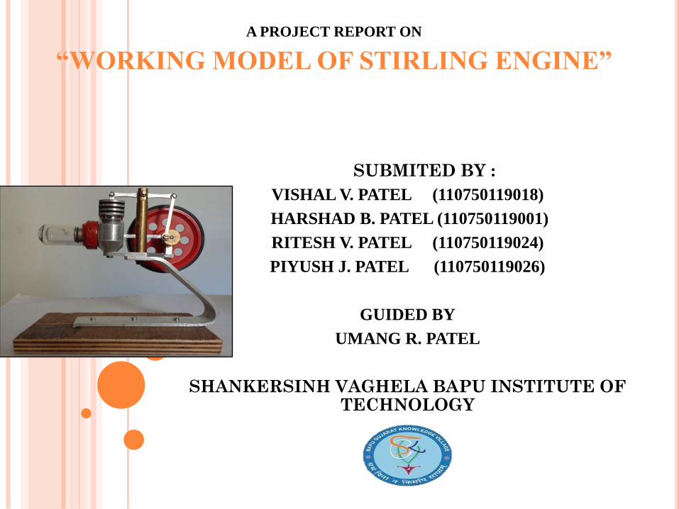
A PROJECT REPORT ON
“WORKING MODEL OF STIRLING ENGINE”
SUBMITED BY :
VISHAL V. PATEL (110750119018)
HARSHAD B. PATEL (110750119001)
RITESH V. PATEL (110750119024)
PIYUSH J. PATEL (110750119026)
GUIDED BY
UMANG R. PATEL
SHANKERSINH VAGHELA BAPU INSTITUTE OF TECHNOLOGY
CONTENTS
ABSTRACT……………………………………..1
INTRODUCTION………………………………3
LITERATURE REVIEW………………………6
METHODOLOGY……………………………...10
SETUP AND PREPARATION………………....14
CONCLUSION………………………………….24
ABSTRACT
1
ABSTRACTWorldwide attempts are being made to increase
the use of our renewable energy sources as well as to use ourcurrent fossil fuel energy sources more efficiently. Waste heatrecovery forms a substantial part of the latter and is the focusof this project.
The aim of this project was to design, build, andreview of Stirling engine capable of generating power. Thisproject provided a great opportunity to gain experience withmechanical design, manufacturing, and the fundamentals ofStirling engines.
We applied our knowledge of thermodynamicsto the design of the engine, and developed formulas to predictits power output at different temperature differentials.
2
INTRODUCTION
3
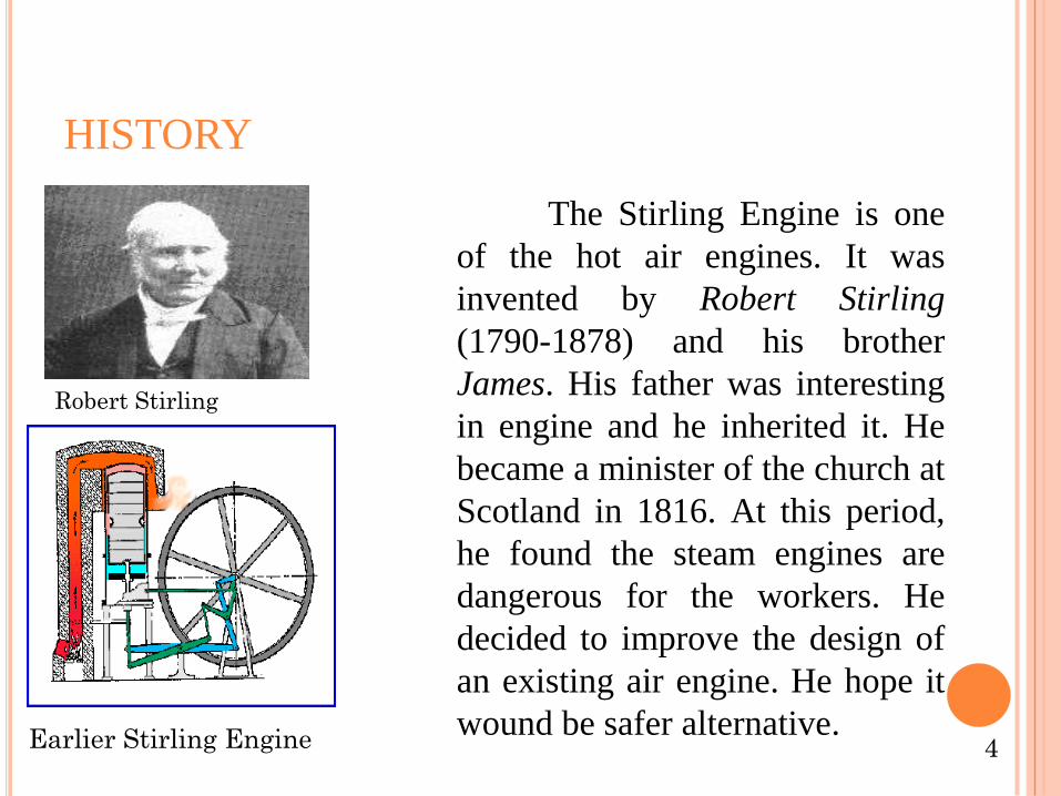
HISTORY
The Stirling Engine is one
of the hot air engines. It was
invented by Robert Stirling
(1790-1878) and his brother
James. His father was interesting
in engine and he inherited it. He
became a minister of the church at
Scotland in 1816. At this period,
he found the steam engines are
dangerous for the workers. He
decided to improve the design of
an existing air engine. He hope it
wound be safer alternative.
Robert Stirling
Earlier Stirling Engine 4
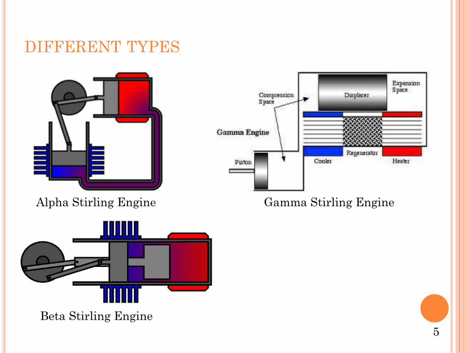
DIFFERENT TYPES
Alpha Stirling Engine Gamma Stirling Engine
Beta Stirling Engine
5
LITERATURE REVIEW
6
Author: DaWei Tanga, Zhigang Lia 20 July 2011
Title : Development and test of a Stirling
engine driven by waste gases for the
micro-CHP system.
Remark : The test results confirm the fact that
Stirling engines driven by mid-high
temperature waste gases are able to
achieve a valuable output power for
engineering application.
7
Author: Halit Karabuluta, Hüseyin Serdar 30
October 2007
Title : An experimental study on the development of
b-type Stirling engine for low and moderate
temperature heat sources
Remark : Experimental results presented in this paper
were obtained by testing the engine with air
as working fluid. The hot end of the
displacer cylinder was heated with a LPG
flame and kept about 200 C constant
temperature throughout the testing period.
8
Author: Chin-Hsiang Cheng 6 April 2010
Title Dynamic simulation of a beta-type Stirling engine
with cam-drive mechanism via the combination of
the thermodynamic and dynamic models.
Remark . An extensive parametric study of the effects
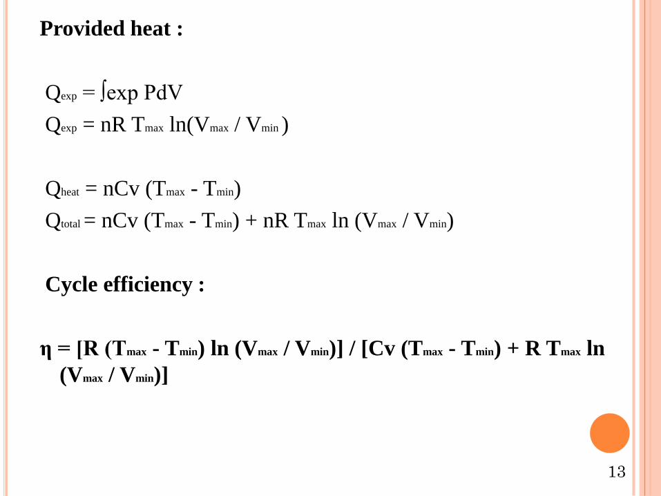
η = [R (Tmax - Tmin) ln (Vmax / Vmin)] / [Cv (Tmax - Tmin) + R Tmax ln
(Vmax / Vmin)]
13
SETUP AND PREPARATION
14
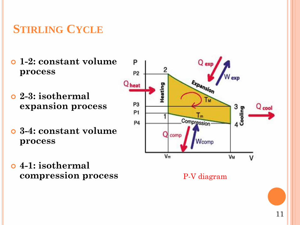
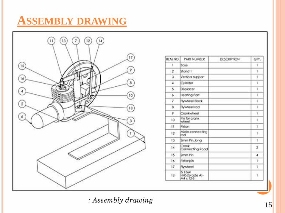
ASSEMBLY DRAWING
15: Assembly drawing
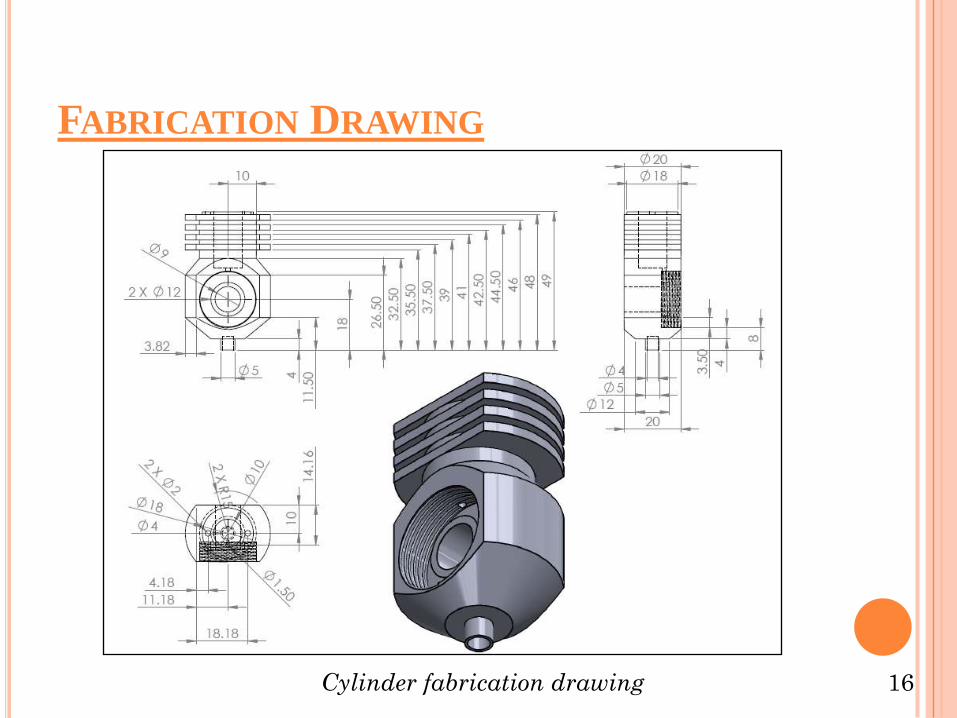
FABRICATION DRAWING
16Cylinder fabrication drawing
17
Clamp fabrication drawingCrank wheel
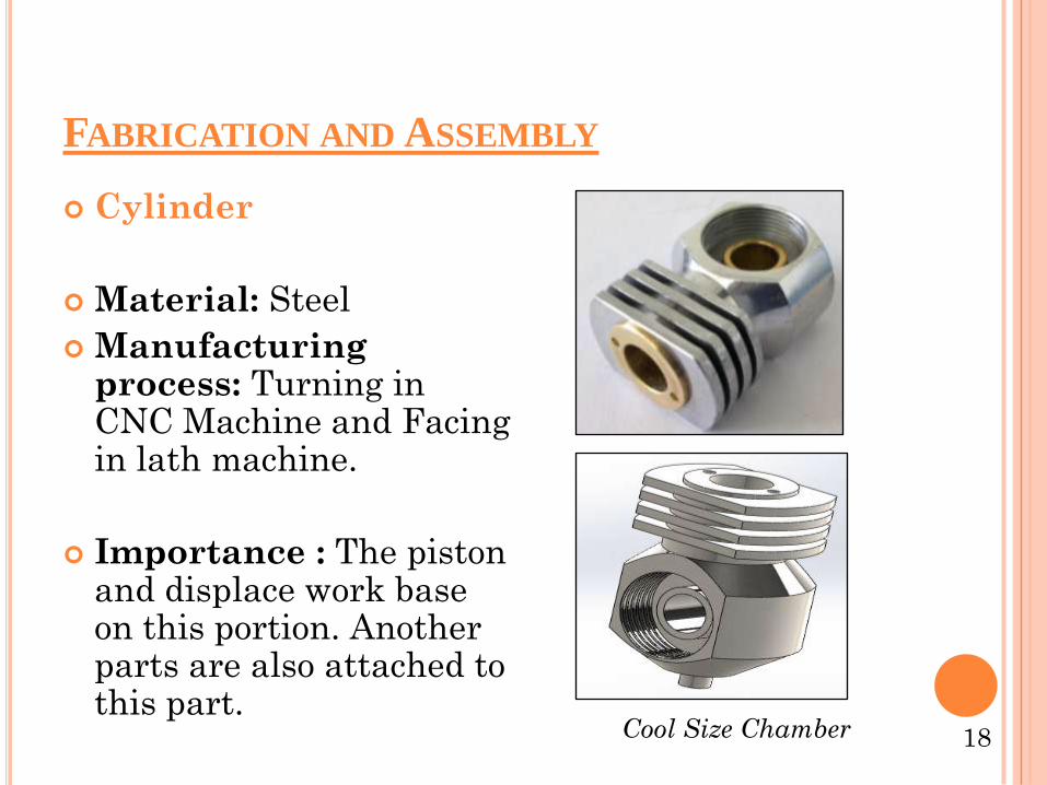
FABRICATION AND ASSEMBLY
Cylinder
Material: Steel
Manufacturing process: Turning in CNC Machine and Facing in lath machine.
Importance : The piston and displace work base on this portion. Another parts are also attached to this part.
18Cool Size Chamber
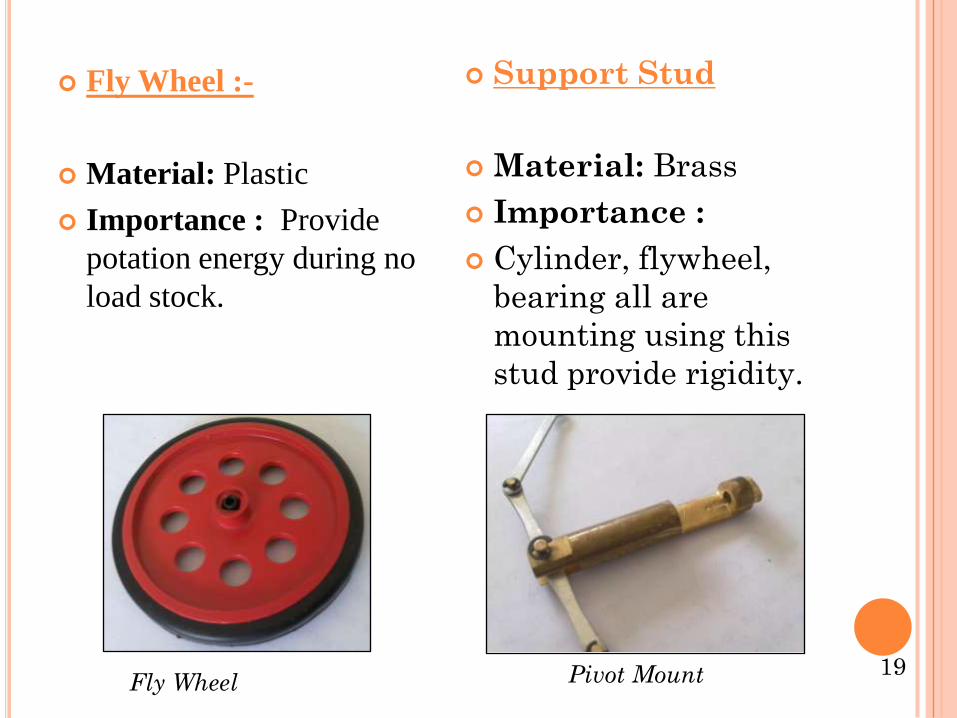
Fly Wheel :-
Material: Plastic
Importance : Provide
potation energy during no
load stock.
Support Stud
Material: Brass
Importance :
Cylinder, flywheel,
bearing all are
mounting using this
stud provide rigidity.
19Fly Wheel Pivot Mount
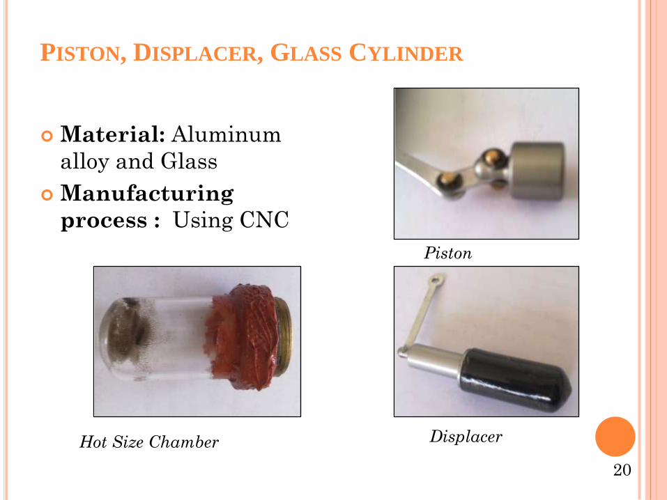
PISTON, DISPLACER, GLASS CYLINDER
Material: Aluminum
alloy and Glass
Manufacturing
process : Using CNC
20
Hot Size Chamber
Piston
Displacer
Assembly Section View Disassembly
21Assembly Section View Assembly Section View
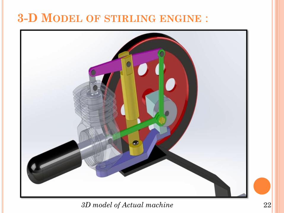
3-D MODEL OF STIRLING ENGINE :
223D model of Actual machine
FABRICATION ASSEMBLY:
23Stirling Engine
CONCLUSION
24
The lack of pressurization may also be an opportunity
to improve the engine. Most successful Stirling
engines in our research were pressurized to some
extent. Currently there are leakage issues on the hot
side preventing pressurization, and more may become
apparent as pressure is increased
Several problems remain to be addressed within the
engine. First among them is the overall lack of useful
work output by the engine. Most of the work is being
absorbed by the friction of the crankshaft and piston
linkages, and possibly by inferior bearings. Further
inspection of the compressor block is recommended to
isolate and rectify these problems.
25
REFERENCES
[1] Institute of Engineering Thermo physics, ChineseAcademy of Sciences, No. 11, BeiSiHuanXi Road, Beijing100190, China Beijing ShiYanTianQiang Technology ompany,Beijing 100076, Chin Received 20 July 2011
[2] Department of Mechanical Technology, Faculty ofTechnical Education, Gazi University, 06500 Teknikokullar,Ankara, Turkey,( Received 30 October 2007)
[3] Department of Mechanical Technology, Faculty ofTechnical Education, Gazi University, Besevler, 06500,Ankara, Turkey Received 16 July 2007,
[4]. Wikipedia free encyclopedia. Stirling engine,www.wikipedia.org/wiki/stirlin-engine, (02/18/2009)