33
–Stirling-type pulse-tube refrigerator for 4 K Ali Etaati R.M.M. Mattheij, A.S. Tijsseling, A.T.A.M. de Waele CASA-Day April 22
| Date post: | 26-Dec-2015 |
| Category: |
Documents |
| Upload: | nancy-mason |
| View: | 214 times |
| Download: | 0 times |
–Stirling-type pulse-tube refrigerator for 4 K
Ali Etaati
R.M.M. Mattheij, A.S. Tijsseling,
A.T.A.M. de Waele
CASA-Day April 22
–Presentation Contents
Introduction. Domain Decomposition (DD) method,
efficiency and robustness. Coupling the 1-D model of the Regenerator and
the 2-D pulse-tube. 1-D modelling of the three-stage PTR. Summary and discussion.
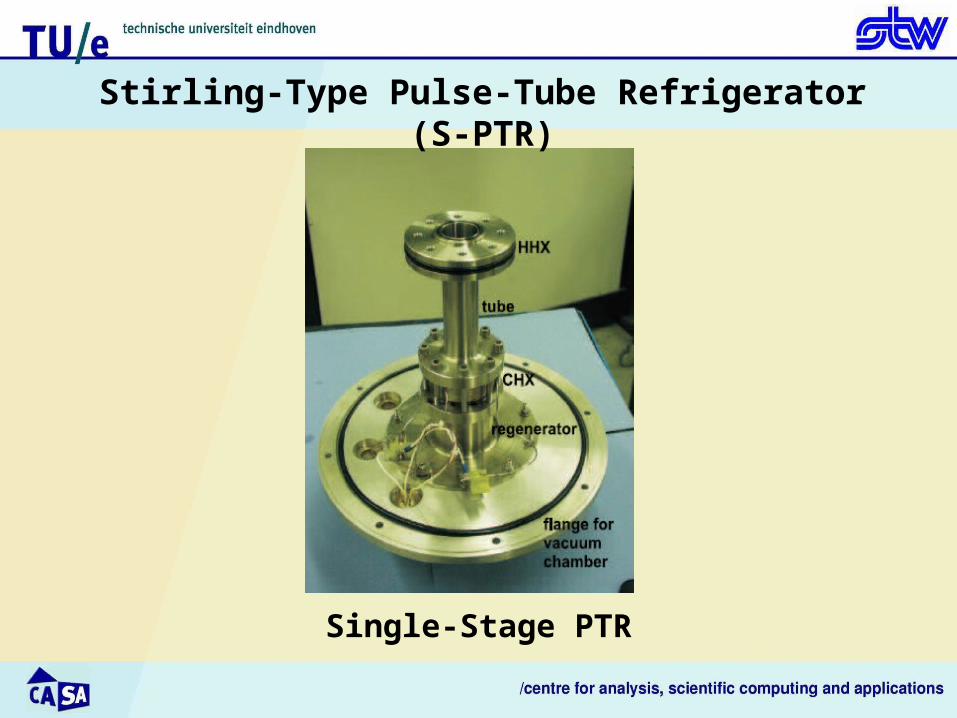
Single-Stage PTR
Stirling-Type Pulse-Tube Refrigerator (S-PTR)

– Single-stage Stirling-PTR
Heat of Compression
Aftercooler
Regenerator
Cold Heat Exchanger
Pulse Tube
Hot Heat Exchanger
Orifice
ReservoirQ Q
Q
Compressor
• Continuum fluid flow,• Newtonian flow,• Ideal gas, • No external forces act on the gas,• Oscillating flow.
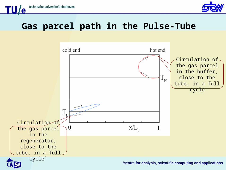
Gas parcel path in the Pulse-Tube
Circulation of the gas parcel in the
regenerator, close to the tube, in a full cycle`
Circulation of the gas parcel in the buffer,
close to the tube, in a full cycle
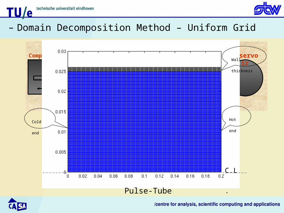
– Domain Decomposition Method – Uniform Grid
Heat of Compression
Aftercooler
Regenerator
Cold Heat Exchanger
Pulse Tube
Hot Heat Exchanger
Orifice
ReservoirQ Q
Q
Compressor
C.L.
Wall thickness
Hot endCold end
Pulse-Tube
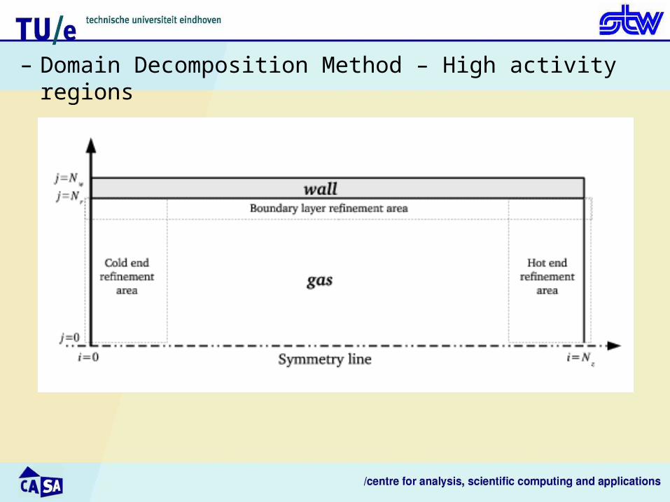
– Domain Decomposition Method – High activity regions

– Domain Decomposition Method – High activity regions
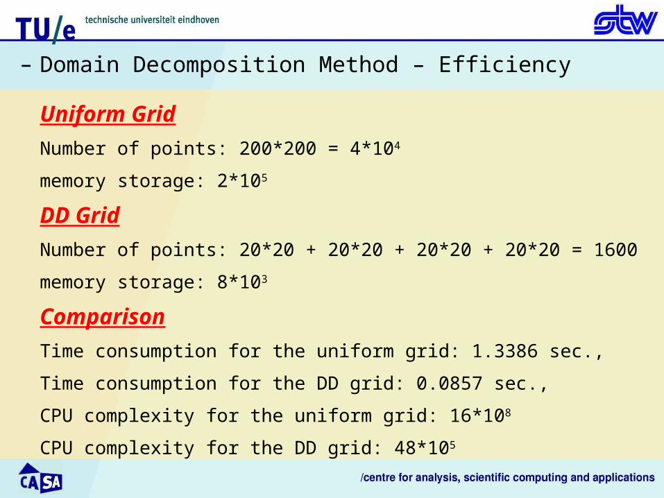
– Domain Decomposition Method – Efficiency
Uniform Grid
Number of points: 200*200 = 4*104
memory storage: 2*105
DD Grid
Number of points: 20*20 + 20*20 + 20*20 + 20*20 = 1600
memory storage: 8*103
Comparison
Time consumption for the uniform grid: 1.3386 sec.,
Time consumption for the DD grid: 0.0857 sec.,
CPU complexity for the uniform grid: 16*108
CPU complexity for the DD grid: 48*105

– Domain Decomposition Method – Error analysis
View line errT errU errV errP
AxialLine 2.2*10-2 1.9*10-2 1.4*10-2 1.2*10-6
RadialLine
4.0*10-2 3.4*10-2 2.2*10-3 8.4*10-6
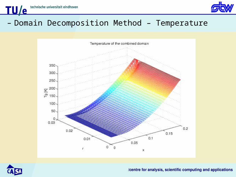
– Domain Decomposition Method – Temperature
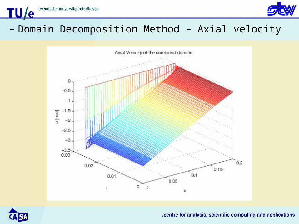
– Domain Decomposition Method – Axial velocity
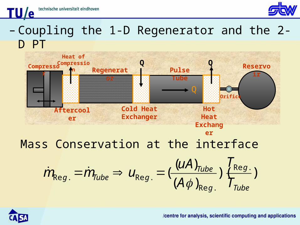
– Coupling the 1-D Regenerator and the 2-D PT
Heat of Compression
Aftercooler
Regenerator
Cold Heat Exchanger
Pulse Tube
Hot Heat Exchanger
Orifice
ReservoirQ Q
Q
Compressor
))()(
)(( .Re
.Re.Re.Re
Tube
g
g
TubegTubeg T
T
A
uAumm
Mass Conservation at the interface

– Coupling Algorithm
Solve the energy equations for both systems (pulse-tube and regenerator).
Iteration Loop
Initial Guess: Solve simultaneously the one-dimensional momentum equations in
the PT and the regenerator as well as applying Darcy's law in the porous
medium to use it as an I.G.
Loop:
a. Solve the momentum equation with Darcy's law only in the regenerator to find
the thermodynamic pressure, P(t), at CHX.
b. Solve the pressure-correction algorithm in the PT two-dimensionally.
d. Compute the axial velocity at the PT’s CHX and use mass conservation to
obtain the B.C. for the velocity in the regenerator, , at CHX.guRe

– Coupling Algorithm
e. Compute the velocity difference at CHX:
f. If go to the next time step. Otherwise go back to step “a" with,
, as the new boundary condition for the regenerator velocity.
oldg
newgdiff uuu .Re.Re
Toludiff newguRe

– Results of coupling the 1-D Reg. and the 2-D PT

– Results of coupling the 1-D Reg. and the 2-D PT

– Results of coupling the 1-D Reg. and the 2-D PT

– Results of coupling the 1-D Reg. and the 2-D PT

Three-stage Stirling-Type Pulse-Tube Refrigerator (S-PTR)
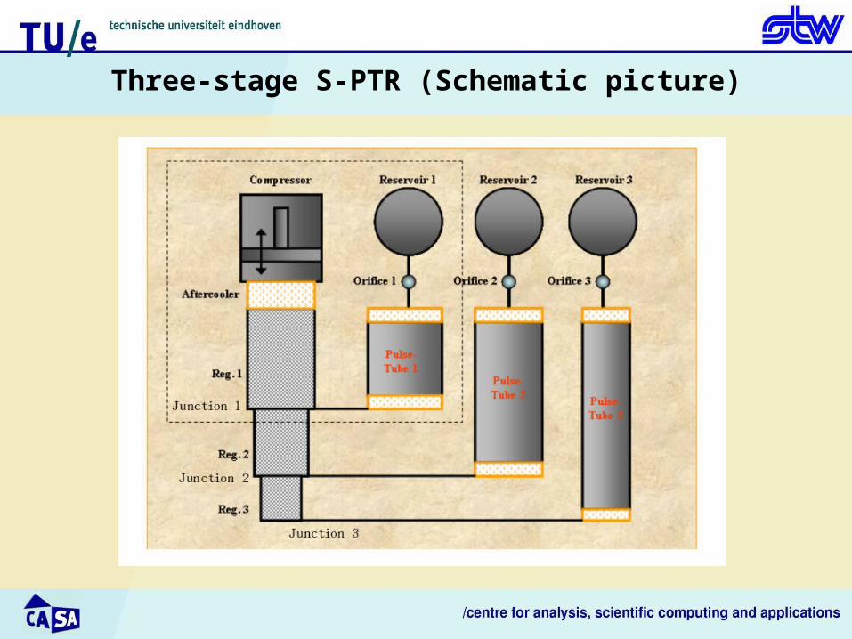
Three-stage S-PTR (Schematic picture)
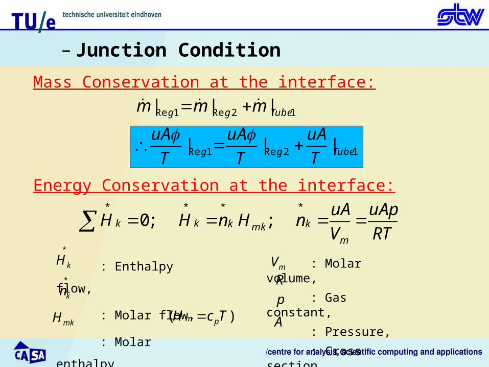
– Junction Condition
Mass Conservation at the interface:
12Re1Re
12Re1Re
|||
|||
Tubegg
Tubegg
T
uA
T
uA
T
uA
mmm
RT
uAp
V
uAnHnHH
m
kmkkkk ****
;;0
Energy Conservation at the interface:
: Enthalpy flow,
: Molar flow,
: Molar enthalpy
*
kH*
kn
mkH
: Molar volume,
: Gas constant,
: Pressure,
: Cross section.
mVR
p
A),( TcH pm

– Junction Condition
Energy Conservation at the interface:
12Re1Re ||| Tubegg uAuAuA
uAR
pcH pk )(
*
Simplified enthalpy flow:
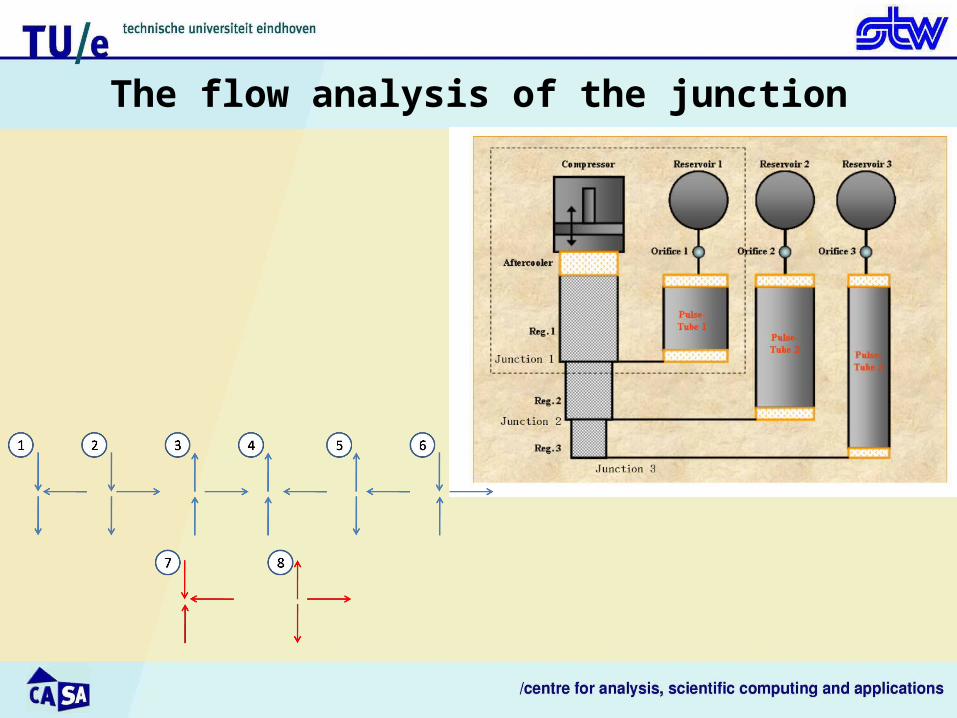
The flow analysis of the junction
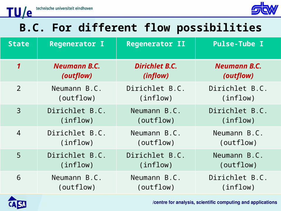
B.C. For different flow possibilitiesState Regenerator I Regenerator II Pulse-Tube I
1 Neumann B.C.(outflow)
Dirichlet B.C.(inflow)
Neumann B.C.(outflow)
2 Neumann B.C.(outflow)
Dirichlet B.C.(inflow)
Dirichlet B.C.(inflow)
3 Dirichlet B.C.(inflow)
Neumann B.C.(outflow)
Dirichlet B.C.(inflow)
4 Dirichlet B.C.(inflow)
Neumann B.C.(outflow)
Neumann B.C.(outflow)
5 Dirichlet B.C.(inflow)
Dirichlet B.C.(inflow)
Neumann B.C.(outflow)
6 Neumann B.C.(outflow)
Neumann B.C.(outflow)
Dirichlet B.C.(inflow)
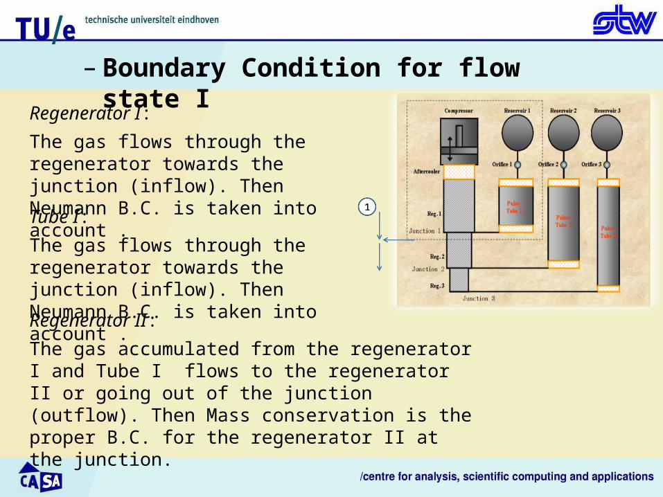
– Boundary Condition for flow state I
Regenerator I:
The gas flows through the regenerator towards the junction (inflow). Then Neumann B.C. is taken into account .
Tube I:
The gas flows through the regenerator towards the junction (inflow). Then Neumann B.C. is taken into account .
Regenerator II:
The gas accumulated from the regenerator I and Tube I flows to the regenerator II or going out of the junction (outflow). Then Mass conservation is the proper B.C. for the regenerator II at the junction.

– Results of the three-stage S-PTR
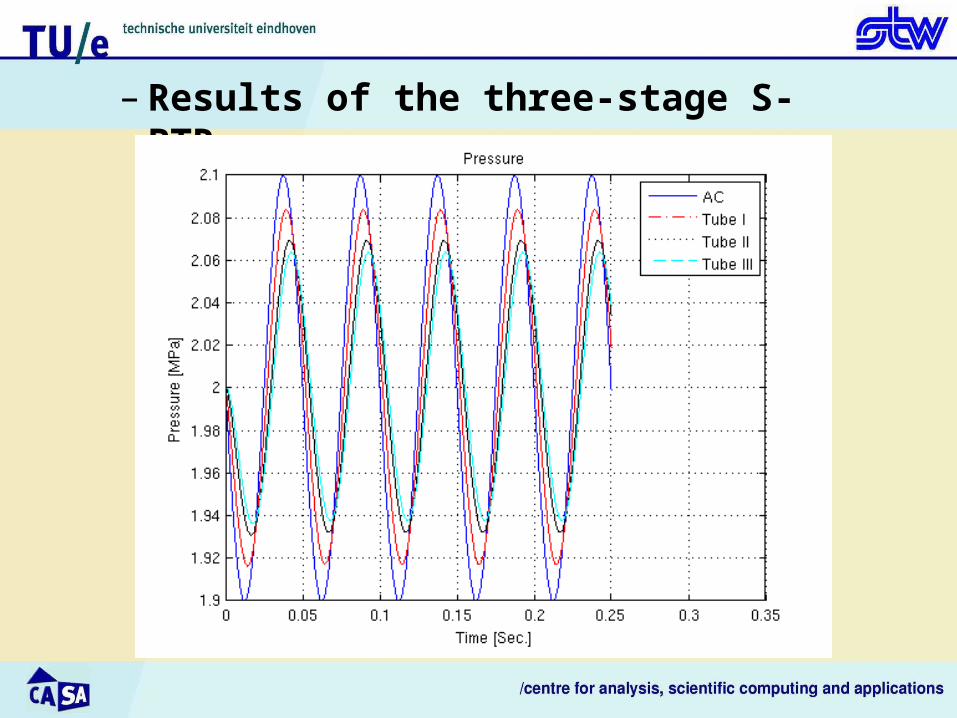
– Results of the three-stage S-PTR
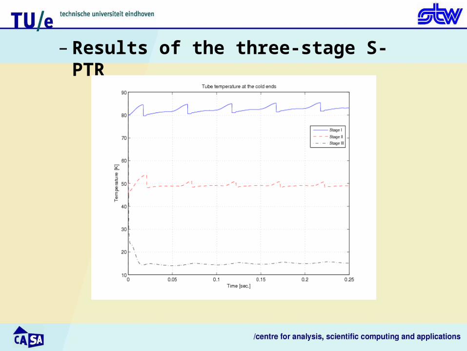
– Results of the three-stage S-PTR
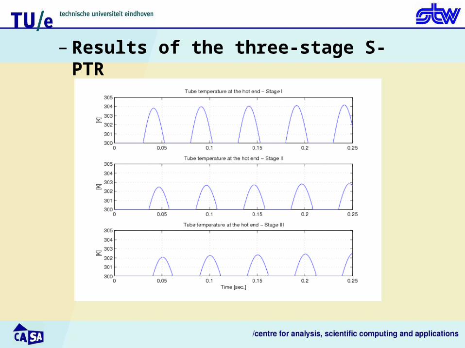
– Results of the three-stage S-PTR

– Summary and remarks
• Modeling the pulse-tube in 2-D: Using a successfully tested pressure-correction algorithm. Improving the model by a Domain Decomposition method. Applying at the same time a pressure-correction algorithm and a
Domain Decomposition method was a challenge. • Coupling the 2-D tube model with the 1-D regenerator model:
Employing an iterative method to apply the proper interface
conditions between two systems. • Modeling the three-stage PTR:
Solving the governing equations for the whole system
simultaneously. Applying the proper interface conditions.
–Current steps of the project
• Apply the non-ideal gas law as well as temperature material
properties to the multi-stage PTR numerically specially for the third
stage of the regenerator.
• Do more numerical simulations to find possible lowest temperatures.

–Thank you for your attention!


