35
STM23 Hardware Manual 920-0021 7/15/08

�
STM23Hardware Manual
920-00217/15/08
Contents
Introduction....................................................................................................................................................................................................................................................................................3Features...............................................................................................................................................................................................................................................................................................3Block.Diagram...............................................................................................................................................................................................................................................................................4Safety.Instructions......................................................................................................................................................................................................................................................................5Getting.Started............................................................................................................................................................................................................................................................................6Mounting.the.Motor+Drive.............................................................................................................................................................................................................................................6Choosing.a.Power.Supply.................................................................................................................................................................................................................................................7
Voltage................................................................................................................................................................................................................................................................................ 7Current................................................................................................................................................................................................................................................................................ 8Connecting.the.Power.Supply...................................................................................................................................................................................................................12
Connecting.the.STM23................................................................................................................................................................................................................................................... 14Connecting.to.the.PC.using.RS-232......................................................................................................................................................................................................14Connecting.to.a.host.using.RS-485........................................................................................................................................................................................................15RS-232.to.RS-485.4-wire.Converter....................................................................................................................................................................................................15Two-Wire.Systems..................................................................................................................................................................................................................................................16RS-232.to.RS-485.2-wire.Converter....................................................................................................................................................................................................16Converting.USB.to.RS-485............................................................................................................................................................................................................................16Assigning.Addresses.............................................................................................................................................................................................................................................17
STM23.Inputs.and.Outputs........................................................................................................................................................................................................................................ 18High.Speed.Digital.Inputs...............................................................................................................................................................................................................................19The.Enable.(EN).Digital.Input.......................................................................................................................................................................................................................21Analog.Input...............................................................................................................................................................................................................................................................22Programmable.Output.......................................................................................................................................................................................................................................23
Reference.Materials............................................................................................................................................................................................................................................................. 25Mechanical.Outlines.............................................................................................................................................................................................................................................25Technical.Specifications.....................................................................................................................................................................................................................................28Torque-Speed.Curves.......................................................................................................................................................................................................................................31Drive/Motor.Heating...........................................................................................................................................................................................................................................32Contacting.Applied.Motion.Products.................................................................................................................................................................................................34LED.Error.Codes......................................................................................................................................................................................................................................................35
�
STM�3 Hardware Manual920-00217/15/08

Introduction
Thank.you.for.selecting.the.Applied.Motion.Products.STM23 Motor+Drive..We.hope.our.dedication.to.perfor-mance;.quality.and.economy.will.make.your.motion.control.project.successful..If.there’s.anything.we.can.do.to.improve.our.products.or.help.you.use.them.better,.please.call.or.fax..We’d.like.to.hear.from.you..Our.phone.number.is.(800).525-1609,.or.you.can.reach.us.by.fax.at.(831)[email protected]..
Features•...Programmable,.micro-stepping.digital.Step.Motor+Driver.in.an.integrated.package•...Operates.from.a.12.to.70.volt.DC.power.supply•...Operates.in.velocity.or.position.mode•...Mid-band.anti-resonance•...Accepts.analog.signals,.digital.signals.and.RS-232.serial.commands•...Step.input.signal.smoothing•...RS-422/485.communication.models•...Optional.encoder.feedback•...STM23S/Q-2.delivers.up.to.120.oz-in•...STM23S/Q-3.delivers.up.to.210.oz-in•...3.-.optically.isolated,.5.to.24.volt.digital.inputs•...Input.filtering.both.hardware.and.software.•...1.-.optically.isolated,.30V.40ma.digital.output•...1.-.0.to.5V.analog.input.for.speed.and.position.control
3
STM�3 Hardware Manual920-0021
7/15/08

Block Diagram
MOSFETPWMPower
Ampli�er
12-70 VDC External
Power Supply
VoltageTempDet.
OverCurrent
Det.
motor
encoder
5 Volt DCPower Supply
DSPDriverController
3.3VDCInternal
LogicSupply
STM23S/Q
OpticalIso
I/O C
onne
ctor
+
OpticalIso
OpticalIso
STEP+
+5VDC (50ma Max)
GND
DigitalFilter
DigitalFilter
DigitalFilter
SoftwareFilter
SoftwareFilter
SoftwareFilter
STEP (5 to 24 Volts): Step Input: Jog CW: Limit CW: Start/Stop: General Purpose
DIR (5 to 24 Volts): Direction Input: Jog CCW: Limit CCW: General Purpose
EN (5 to 24 Volts): Enable Input: Reset Input: Change Speed: General Purpose
I/O Con�gurations
Status
AIN
OpticalIso
RS-232 or RS-485
Com
mCo
nnPo
wer
Conn
GND
+5V
STEP-
DIR+DIR-
EN+EN-
OUT+OUT-
RS-232TX, RX, GND, +5V
orRS-485
RX+, RX-, TX+, TX-, GND
-
OUT (30V, 40ma): Brake Output: Alarm Output: Motion Output:Tach Output: General Purpose
Optional
Block Diagram
�
STM�3 Hardware Manual920-00217/15/08

Safety Instructions.Only.qualified.personnel.are.permitted.to.transport,.assemble,.commission,.and.maintain.this.equipment..Properly.quali-fied.personnel.are.persons.who.are.familiar.with.the.transport,.assembly,.installation,.commissioning.and.operation.of.motors,.and.who.have.the.appropriate.qualifications.for.their.jobs..The.qualified.personnel.must.know.and.observe.the.following.standards.and.regulations:IEC.364.resp..CENELEC.HD.384.or.DIN.VDE.0100IEC.report.664.or.DIN.VDE.0110National.regulations.for.safety.and.accident.prevention.or.VBG.4
To.minimize.the.risk.of.potential.safety.problems,.you.should.follow.all.applicable.local.and.national.codes.that.regulate.the.installation.and.operation.of.your.equipment..These.codes.vary.from.area.to.area.and.it.is.your.responsibility.to.de-termine.which.codes.should.be.followed,.and.to.verify.that.the.equipment,.installation,.and.operation.are.in.compliance.with.the.latest.revision.of.these.codes.Equipment.damage.or.serious.injury.to.personnel.can.result.from.the.failure.to.follow.all.applicable.codes.and.standards..We.do.not.guarantee.the.products.described.in.this.publication.are.suitable.for.your.particular.application,.nor.do.we.assume.any.responsibility.for.your.product.design,.installation,.or.operation.
•...Read.all.available.documentation.before.assembly.and.commissioning..Incorrect.handling.of.products.in.this.manual.can.result.in.injury.and.damage.to.persons.and.machinery..Strictly.adhere.to.the.technical.information.on.the.installation.requirements.•...It.is.vital.to.ensure.that.all.system.components.are.connected.to.earth.ground..Electrical.safety.is.impossible.with-out.a.low-resistance.earth.connection.•...The.STM23.drives.contain.electrostatically.sensitive.components.that.can.be.damaged.by.incorrect.handling..Discharge.yourself.before.touching.the.product..Avoid.contact.with.high.insulating.materials.(artificial.fabrics,.plastic.film,.etc.)..Place.the.product.on.a.conductive.surface.•...During.operation.keep.all.covers.and.cabinet.doors.shut..Otherwise,.there.are.deadly.hazards.that.could.pos-sibility.cause.severe.damage.to.health.or.the.product.•...In.operation,.depending.on.the.degree.of.enclosure.protection,.the.product.can.have.bare.components.that.are.live.or.have.hot.surfaces..Control.and.power.cables.can.carry.a.high.voltage.even.when.the.motor.is.not.rotat-ing.•...Never.pull.out.or.plug.in.the.product.while.the.system.is.live..There.is.a.danger.of.electric.arcing.and.danger.to.persons.and.contacts.•...After.powering.down.the.product,.wait.at.least.ten.minutes.before.touching.live.sections.of.the.equipment.or.undoing.connections.(e.g.,.contacts,.screwed.connections)..Capacitors.can.store.dangerous.voltages.for.long.peri-ods.of.time.after.power.has.been.switched.off..To.be.safe,.measure.the.contact.points.with.a.meter.before.touching.
Be.alert.to.the.potential.for.personal.injury..Follow.the.recommended.precautions.and.safe.operating.practices.included.with.the.alert.symbols..Safety.notices.in.this.manual.provide.important.information..Read.and.be.familiar.with.these.instructions.before.attempting.installation,.operation,.or.maintenance..The.purpose.of.this.section.is.to.alert.users.to.possible.safety.hazards.associated.with.this.equipment.and.the.precautions.that.need.to.be.taken.to.reduce.the.risk.of.personal.injury.and.damage.to.the.equipment.Failure.to.observe.these.precautions.could.result.in.serious.bodily.injury,.damage.to.the.equipment,or.operational.dif-ficulty.
�
STM�3 Hardware Manual920-0021
7/15/08

Getting StartedThis.manual.describes.the.use.of.four.different.drive.models..What.you.need.to.know.and.what.you.must.have.depends.on.the.drive.model..For.all.models,.you’ll.need.the.following:
•...a.12.-.70.volt.DC.power.supply..Please.read.the.section.entitled.Choosing.a.Power.Supply.for.help.in.choosing.the.right.power.supply.•...a.small.flat.blade.screwdriver.for.tightening.the.connectors.(included).•...a.personal.computer.running.Microsoft.Windows.98,.2000,.NT,.Me.,.XP.or.Vista.•...The.Applied.Motion.CD.(included)•...An.Applied.Motion.programming.cable.(included.in.RS-232.Models,.RS-485.converters.are.available.from.AMP)
If.you’ve.never.used.an.STM23.drive.before.you’ll.need.to.get.familiar.with.the.drive.and.the.set.up.software.before.you.try.to.deploy.the.system.in.your.application..We.strongly.recommend.the.following:
1....For.-Q.drives,.install.the.ST.Configurator™.and.Q.Programmer™.software.applications.from.the.CD..For.S.models,...........install.the.ST.Configurator™.
2....Launch.the.software.by.clicking.Start...Programs...Applied.Motion...
3....Connect.the.drive.to.your.PC.using.the.programming.cable..When.using.RS-485,.it.must.be.set.up.in.the.4-Wire.............configuration.(See.“Connecting.to.a.host.using.RS-485”.below).
4....Connect.the.drive.to.the.power.supply.
5....Apply.power.to.the.drive.
6....The.software.will.recognize.your.drive,.display.the.model.and.firmware.version.and.be.ready.for.action.
Mounting the Motor+DriveAs.with.any.stepper.motor.the.STM23.Drives.must.be.mounted.so.as.to.provide.maximum.heat-sinking.and.air-flow..Keep.space.around.the.Motor+Drive.to.allow.convected.air-flow.
•...Never use your drive in a space where there is no air flow or where other devices cause the sur- rounding air to be more than 40°C.
•...Never put the drive where it can get wet or where metal or other electrically conductive particles can get on the circuitry.
•...Always provide air-flow around the drive.
�
STM�3 Hardware Manual920-00217/15/08

Choosing a Power SupplyWhen.choosing.a.power.supply,.there.are.many.things.to.consider..If.you.are.manufacturingEquipment.that.will.be.sold.to.others,.you.probably.want.a.supply.with.all.the.safety.agency.approvals..If.size.and.weight.are.an.issue.use.a.switching.supply.
You.must.also.decide.what.size.of.power.supply.(in.terms.of.voltage.and.current).is.needed.for.your.application.
VoltageThe.STM23.series.drives.are.designed.to.give.optimum.performance.between.24.and.48.volts.DC..Choosing.the.voltage.depends.on.the.performance.needed.and.Motor+Drive.heating.that.is.acceptable.and/or.does.not.cause.a.drive.over-temperature..Higher.voltages.will.give.higher.speed.performance.but.will.cause.the.Motor+Drive.to.oper-ate.at.higher.temperatures..Using.power.supplies.with.voltage.outputs.that.are.near.the.drive.maximum.may.reduce.the.operational.duty-cycle.significantly..See.the.chart.below.to.determine.thermal.performance.at.different.power.supply.voltages
If you choose an unregulated power supply, make sure the no load voltage of the supplydoes not exceed the drive’s maximum input voltage specification.
..
STM23-3 Max Duty cycle vs Speed5 Amps @Ambient of 40°C
6.4" x 6.4" x .25" Aluminum Plate
0
20
40
60
80
100
0 10 20 30 40 50Speed (RPS)
%D
uty
Cyc
le
12V Duty Cyc le24V Duty Cyc le48V Duty Cyc le65V Duty Cyc le
STM23-2 Max Duty cycle vs Speed5 Amps @Ambient of 40°C
6.4" x 6.4" x .25" Aluminum Plate
0
20
40
60
80
100
0 10 20 30 40 50Speed (RPS)
%Du
tyCy
cle
12V Duty Cyc le24V Duty Cyc le48V Duty Cyc le65V Duty Cyc le
�
STM�3 Hardware Manual920-0021
7/15/08

CurrentThe.maximum.supply.currents.required.by.the.STM23.Series.Motor+Drives.are.shown.in.the.chart.below.with.different.power.supply.voltage.inputs..You.will.note.in.the.chart.that.the.Motor+Drive.does.not.draw.as.much.current.as.what.the.motor.operates.at..That’s.because.the.STM.drives.use.switching.amplifiers,.converting.a.high.voltage.and.low.current.into.lower.voltage.and.higher.current..The.more.the.power.supply.voltage.exceeds.the.motor.voltage,.the.less.current.you’ll.need.from.the.power.supply..
Also.note.that.the.current.draw.is.significantly.different.at.higher.speeds.depending.on.the.torque.load.to.the.motor..Estimating.your.current.needs.may.require.a.good.analysis.of.the.load.the.motor.will.encounter.
.
STM23-2 24V Power Supply Current
0
2040
60
80
100120
140
0 10 20 30 40 50Speed (RPS)
Torq
ue(O
z-In
)
0 .00
0 .501 .00
1 .50
2 .00
2 .503 .00
3 .50
Am
ps
TorqueO z /In
SupplyC urrent
SupplyC urrentNo Load
STM23-2 12V Power Supply Current
0
2040
60
80
100120
140
0 10 20 30 40 50Speed (RPS)
Torq
ue(O
z-In
)
0 .00
0 .50
1 .00
1 .50
2 .00
2 .50
3 .00
Amps
TorqueO z /In
SupplyC urrent
SupplyC urrentNo Load
�
STM�3 Hardware Manual920-00217/15/08

STM23-2 48V Power Supply Current
0
2040
60
80
100120
140
0 10 20 30 40 50Speed (RPS)
Torq
ue(O
z-In
)
0 .00
0 .50
1 .00
1 .50
2 .00
2 .50
3 .00
Am
ps
TorqueO z /In
SupplyC urrent
SupplyC urrentNo Load
STM23-2 70V Power Supply Current
0
2040
60
80
100120
140
0 10 20 30 40 50Speed (RPS)
Torq
ue(O
z-In
)
0 .00
0 .501 .00
1 .50
2 .00
2 .503 .00
3 .50
Am
ps
TorqueO z /In
SupplyC urrent
SupplyC urrentNo Load
�
STM�3 Hardware Manual920-0021
7/15/08

STM23-3 12V Power Supply Current
0
50
100
150
200
250
0 10 20 30 40 50Speed (RPS)
Torq
ue(O
z-In
)
0 .00
0 .50
1 .00
1 .50
2 .00
2 .50
3 .00
3 .50
Am
ps
TorqueO z /In
SupplyC urrent
SupplyC urrentNo Load
STM23-3 24V Power Supply Current
0
50
100
150
200
250
0 10 20 30 40 50Speed (RPS)
Torq
ue(O
z-In
)
0 .00
0 .50
1 .00
1 .50
2 .00
2 .50
3 .00
3 .50
Am
ps
TorqueO z /In
SupplyC urrent
SupplyC urrentNo Load
10
STM�3 Hardware Manual920-00217/15/08

STM23-3 48V Power Supply Current
0
50
100
150
200
250
0 10 20 30 40 50Speed (RPS)
Torq
ue(O
z-In
)
0 .00
0 .50
1 .00
1 .50
2 .00
2 .50
3 .00
3 .50
Am
ps
TorqueO z /In
SupplyC urrent
SupplyC urrentNo Load
STM23-3 70V Power Supply Current
0
50
100
150
200
250
0 10 20 30 40 50Speed (RPS)
Torq
ue(O
z-In
)
0 .000 .501 .001 .502 .002 .503 .003 .504 .00
Am
ps
TorqueO z /In
SupplyC urrent
SupplyC urrentNo Load
11
STM�3 Hardware Manual920-0021
7/15/08

To Power Supply +
To Earth Ground
To Power Supply –
Connecting the Power Supply
If.you.need.information.about.choosing.a.power.supply,.please.read.“Choosing.a.Power.Supply”.located.above.in.this.manual.
Connect.the.motor.power.supply.“+”.terminal.to.the.driver.terminal.labeled.“+”..Connect.power.supply.“-”.to.the.drive.terminal.labeled.“-”..Use.16.to.20-gauge.wire..The.STM23.drives.contain.an.internal.fuse.that.connect.to.the.power.sup-ply.+.terminal..This.fuse.is.not.user.replaceable..If.you.want.to.install.a.user.serviceable.fuse.in.your.system.install.a.4.amp.fast.acting.fuse.in.line.with.the.+.power.supply.lead.
Be careful not to reverse the wires. Reverse connection may open the internal fuse on your driver and void your warranty.
1�
STM�3 Hardware Manual920-00217/15/08

If.you.plan.to.use.a.regulated.power.supply.you.may.encounter.a.problem.with.regeneration..If.you.rapidly.decelerate.a.load.from.a.high.speed,.much.of.the.kinetic.energy.of.that.load.is.transferred.back.to.the.power.supply..This.can.trip.the.over-voltage.protection.of.a.switching.power.supply,.causing.it.to.shut.down..We.offer.the.RC050.“regeneration.clamp”.to.solve.this.problem..If.in.doubt,.buy.an.RC050.for.your.first.installation..If.the.“regen”.LED.on.the.RC050.never.flashes,.you.don’t.need.the.clamp.
RC050 Regen Clamp
13
STM�3 Hardware Manual920-0021
7/15/08

Connecting to the PC using RS-232•...Locate.your.computer.within.8.feet.of.the.drive.•...Your.drive.was.shipped.with.a.communication.cable..Plug.the.large.end.into.the.serial.port.of.your.PC.and.. ......the.small.end.into.the.PC/MMI.jack.on.your.drive..Secure.the.cable.to.the.PC.with.the.screws.on.the.sides.
Never connect a drive to a telephone circuit. It uses the same connectors andcords as telephones and modems, but the voltages are not compatible.
If.your.PC.does.not.have.a.serial.port,.you.should.purchase.a.“USB.Serial.Converter”..We.have.had.good.results.with.the.Port.Authority.“USB.Serial.DB9”.Adapter.from.www.CablesToGo.com.and.with.the.SW1301.from.www.SewellDirect.com.
For.laptops,.a.PCMCIA.converter.card.is.a.good.choice..Our.applications.engineers.use.the.SSP-100.from.Sewell.Direct..
ground (to PC ground)
TX (to PC RX) +5V Supply (for Hub)
RX (to PC TX)
Pin Assignments of the PC/MMI Port(RJ11 connector)
Connecting the STM23
1�
STM�3 Hardware Manual920-00217/15/08

Connecting to a host using RS-485RS-485.allows.you.to.connect.more.than.one.drive.to.a.single.host.PC,.PLC,.HMI.or.other.computer..It.also.allows.the.communication.cable.to.be.long.(more.than.1000.feet)..But.the.device.to.which.you.connect.must.have.an.RS-485.port
.
Pin.diagram.is.shownabove..Wiring.diagrams.can.be.found.on.the.next.page..We.recommend.the.use.of.Category.5.cable..It.is.widely.used.for.computer.networks,.it.is.inexpensive,.easy.to.get.and.certified.for.quality.and.data.integrity.
The.STM23.drives.can.be.used.with.either.two-wire.or.four-wire.RS-485.implementations,.however.with.using.ST.Con-figurator.the.drives.must.be.connected.in.the.four-wire.configuration..The.connection.can.be.point.to.point.(i.e..one.drive.and.one.host).or.a.multi-drop.network.(one.host.and.up.to.32.drives).
Four-Wire.Systems.utilize.separate.transmit.and.receive.wires..One.pair.of.wires.must.connect.the.host.computer’s.transmit.signals.to.each.drive’s.RX+.and.RX-.terminals..Another.pair.connects.the.TX+.and.TX-.drive.terminals.to.the.host.computer’s.receive.signals..A.logic.ground.terminal.is.provided.on.each.drive.and.can.be.used.to.keep.all.drives.at.the.same.ground.potential..This.terminal.connects.internally.to.the.DC.power.supply.return.(V-),.so.if.all.the.drives.on.the.RS-485.network.are.powered.from.the.same.supply.it.is.not.necessary.to.connect.the.logic.grounds..You.should.still.connect.one.drive’s.GND.terminal.to.the.host.computer.ground.
Four-wire.systems.are.better.than.two-wire.types.because.the.host.never.needs.to.disable.its.transmitter,.which.simplifies.your.software..Some.converters.make.this.process.very.difficult.to.implement.and.can.delay.communications.
RS-232 to RS-485 4-wire ConverterModel.117701.from.Jameco.Electronics.(800-831-4242).works.well.for.converting.your.PC’s.RS-232.port.to.four.wire.RS-485..This.adaptor.is.for.a.25.pin.serial.port..If.you.are.like.most.people.and.have.a.9.pin.serial.port.on.your.PC,.you.will.also.need.to.purchase.Jameco.cable.31721.Connect.as.follows:
..
Set.the.switches.for.DCE.and.TxON,RxON..Don’t.forget.to.plug.in.the.DC.power.adaptor.that.comes.with.the.unit.
.
GNDTX–TX+RX–RX+
to PC RX+to PC RX-
to PC TX+to PC TX-
to PC GND
Drive #1 Drive #2 Drive #3
RX+-
RX--
TX+-
TX-
GN
D
RX+-
RX--
TX+-
TX-
GN
D
RX+-
RX--
TX+-
TX-
GN
D
1�
STM�3 Hardware Manual920-0021
7/15/08

Two-Wire SystemsTransmit.and.receive.on.the.same.pair.of.wires.can.lead.to.trouble..The.host.must.not.only.disable.its.transmitter.before.it.can.receive.data,.it.must.do.so.quickly,.before.a.drive.begins.to.answer.a.query..The.ST.drives.include.a.“transmit.delay”.parameter.that.can.be.adjusted.to.compensate.for.a.host.that.is.slow.to.disable.its.transmitter..This.adjustment.can.be.made.over.the.network.using.the.TD.command,.or.it.can.be.set.using.the.ST.Configurator.software..It.is.not.neces-sary.to.set.the.transmit.delay.in.a.four.wire.system.
RS-232 to RS-485 2-wire ConverterModel.485-25E.from.Integrity.Instruments.(800-450-2001).works.well.for.converting.your.PC’s.RS-232.port.to.RS-485..It.comes.with.everything.you.need..Connect.the.adaptor’s.“B”.pin.to.the.STM23.drive’s.TX+.and.RX+.terminals..Connect.“A”.to.the.drive’s.TX-.and.RX-.terminals.
Converting USB to RS-485The.USB-COMi-M.from.www.byterunner.com.is.an.excellent.choice.for.USB.to.RS-485.conversion..Set.SW1.to.ON.and.SW2-4.to.OFF..On.the.USB-COMi-M.screw.terminal.connector:.pin1.goes.to.RX-.and.TX-..Connect.pin.2.to.RX+.and.TX+..Pin.6.is.ground..The.DB-9.is.not.used.
to PC TX+ (B)to PC TX- (A)
to PC GND
Drive #1 Drive #2 Drive #3Drive #1
RX+-
RX--
TX+-
TX-
GN
D
RX+-
RX--
TX+-
TX-
GN
D
RX+-
RX--
TX+-
TX-
GN
DRS-485 Two Wire System
1�
STM�3 Hardware Manual920-00217/15/08

Assigning AddressesBefore.wiring.the.entire.system,.you’ll.need.to.connect.each.drive.individually.to.the.host.computer.so.that.a.unique.address.can.be.assigned.to.each.drive..Use.the.programming.cable.and.the.ST.Configurator™.software.that.came.with.your.drive.for.this.purpose.
Connect.the.drive.to.your.PC.and.then.launch.the.ST.Configurator™.software..Finally,.apply.power.to.your.drive..If.you.have.already.configured.your.drive,.then.you.should.click.the.Upload.button.so.that.the.ST.Configurator™.settings.match.those.of.your.drive..Click.on.the.Motion.button,.then.select.the.“SCL”.operating.mode..If.you.have.a.Q.drive,.you.may.want.to.select.“Q.Programming”..Either.way,.you’ll.see.the.RS-485.Address.panel.appear..Just.click.on.the.address.character.of.your.choice..You.can.use.the.numerals.0..9.or.the.special.characters.!.“.#.$.%.&.‘.(.).*.+.,.-.../.:.;.<.=.>.?.@...Just.make.sure.that.each.drive.on.your.network.has.a.unique.address..If.you.are.using.a.2.wire.network,.you.may.need.to.set.the.Transmit.Delay,.too..10.milliseconds.works.on.the.adapters.we’ve.tried..Once.you’ve.made.your.choices,.click.Download.to.save.the.settings.to.your.drive.
1�
STM�3 Hardware Manual920-0021
7/15/08

STM23 Inputs and OutputsThe ST drives have three types of inputs:
•...High.speed.digital.inputs.for.step.&.direction.commands.or.encoder.following,.5.to.24.volt.logic•...Digital.input.for.other.signals,.5.-.24.volt.logic•...Analog.input.for.analog.speed.and.positioning.modes
All drives include 3 digital inputs and 1 analog input.•...STEP & DIR:.digital.signals.for.commanding.position..Quadrature.signals.from.encoders.can.also.be.used..These.inputs.can.also.be.connected.to.sensors,.switches.and.other.devices.for.use.with.Q.and.Si™.commands.such.as.Wait.Input,.Seek.Home,.Feed.to.Sensor,.If.Input.and.others..When.not.being.used.for.the.Step.&.Direction.function.these.inputs.can.be.use.for.CW.&.CCW.Limit,.CW.&.CCW.Jogging.and.Run/Stop.&.Direction.Velocity.modes.•...EN:.software.programmable.input.can.be.used.for.motor.enable.or.alarm.reset..This.input.can.also.be.con-nected.to.a.sensor,.switch.and.other.devices.for.use.with.Wait.Input,.Seek.Home,.Feed.to.Sensor,.If.Input.and.other.commands.•...AIN:.analog.velocity.or.position.command.signal..0-5V.with.gain,.filtering,.offset.and.dead-band.settings.
Connector Pin Diagram
STEP+STEP-DIR+DIR-EN+EN-OUT+OUT-+5VAINGND
RES
inside driveSTEP+
STEP-I/O
Conn
ecto
r
DIR+
DIR-
EN+
EN-
OUT+
OUT-
AIN
GND
SignalConditioning
+5V 50ma Limit
1�
STM�3 Hardware Manual920-00217/15/08

High Speed Digital InputsThe.STM23-Q.and.STM23-Si.drives.include.two.high-speed.inputs.called.STEP.and.DIR..They.accept.5.to.24.volt.sin-gle-ended.or.differential.signals,.up.to.2.MHz..Typically.these.inputs.connect.to.an.external.controller.that.provides.step.&.direction.command.signals..You.can.also.connect.a.master.encoder.to.the.high-speed.inputs.for.“following”.applica-tions..Or.you.can.use.these.inputs.with.Wait.Input,.If.Input,.Feed.to.Sensor,.Seek.Home.and.other.L.or.Q.commands.
Connection.diagrams.follow.
.
Connecting to indexer with Sinking Outputs
.
Connecting to indexer with Sourcing Outputs
.
Connecting to Indexer with Differential Outputs(Many.High.Speed.Indexers.have.Differential.Outputs)
5 to 24VHighSpeedInputs
+5 to +24V OUT DIR+
DIR DIR-
STEP+
STEP STEP-
Indexerwith
SinkingOutputs
5 to 24VHighSpeedInputs
COM DIR-
DIR DIR+
STEP-
STEP STEP+
Indexerwith
SourcingOutputs
5 to 24VHighSpeedInputs
DIR+ DIR+
DIR- DIR-
STEP+
STEP-
STEP+
STEP-
1�
STM�3 Hardware Manual920-0021
7/15/08

Wiring for Encoder Following
.
Using Mechanical Switches
S or Qdrive
MasterEncoder
GND
DIR-
DIR+
STEP-
STEP+
GND
B-
B+
A-
A+
S or QDrive
+ DIR+
DIR-
STEP+
- STEP-
5 to 24VDC
PowerSupply
direction switch
run/stop switch(closed=run)
�0
STM�3 Hardware Manual920-00217/15/08

The Enable (EN) Digital InputAs.mentioned.in.the.previous.section,.the.high-speed.STEP.and.DIR.inputs.are.designed.for.high.speed.operation..The.Enable.digital.input.is.designed.for.low.speed.digital.input.operation.between.5.and.24.volts.DC.
Note:.If.current.is.flowing.into.or.out.of.an.input,.the.logic.state.of.that.input.is.low.or.closed..If.no.current.is.flowing,.or.the.input.is.not.connected,.the.logic.state.is.high.or.open.
The.diagrams.on.the.following.pages.show.how.to.connect.the.input.to.various.commonly.used.devices.
.
Connecting the Input to a Switch or Relay
.
Connecting an NPN Type Proximity Sensor to an input(When.prox.sensor.activates,.input.goes.low).
.
Connecting an PNP Type Proximity Sensor to an input(When.prox.sensor.activates,.input.goes.low).
S or QDrivesSwitch or Relay
(closed = logic Low)
EN-
EN+5-24VDC
PowerSupply -
+
S or QDriveNPN
ProximitySensor
EN-
EN+output
+
–
5-24VDC
PowerSupply
-
+
S or QDrive
PNPProximity
SensorEN+
output+
–
EN-
5-24VDC
PowerSupply
-
+
�1
STM�3 Hardware Manual920-0021
7/15/08

Analog InputThe.STM23.drives.feature.an.analog.input..The.input.can.accept.a.signal.range.of.0.to.5.VDC..The.drive.can.be.con-figured.to.operate.at.a.speed.or.position.that.is.proportional.to.the.analog.signal..Use.the.ST.Configurator.software.to.set.the.signal.range,.offset,.dead-band.and.filter.frequency..The.STM23.Drives.provide.a.+5VDC.50ma.output.that.can.be.used.to.power.external.devices.such.as.potentiometers..It.is.not.the.most.accurate.Supply.for.reference,.for.more.precise.readings.use.an.external.supply.that.can.provide.the.desired.accuracy.
..
Connecting a Potentiometer to the Analog Input
inside drive
AIN
GND
SignalConditioning
+5V 50ma Limit
I/OCo
nnec
tor
1-10k pot
cw
ccw
GND
AIN
+5V OUT
��
STM�3 Hardware Manual920-00217/15/08
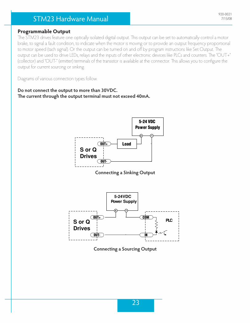
Programmable OutputThe.STM23.drives.feature.one.optically.isolated.digital.output..This.output.can.be.set.to.automatically.control.a.motor.brake,.to.signal.a.fault.condition,.to.indicate.when.the.motor.is.moving.or.to.provide.an.output.frequency.proportional.to.motor.speed.(tach.signal)..Or.the.output.can.be.turned.on.and.off.by.program.instructions.like.Set.Output..The.output.can.be.used.to.drive.LEDs,.relays.and.the.inputs.of.other.electronic.devices.like.PLCs.and.counters..The.“OUT+”.(collector).and.“OUT-”.(emitter).terminals.of.the.transistor.is.available.at.the.connector..This.allows.you.to.configure.the.output.for.current.sourcing.or.sinking.
Diagrams.of.various.connection.types.follow.
Do not connect the output to more than 30VDC.The current through the output terminal must not exceed 40mA.
.
.
Connecting a Sinking Output.
Connecting a Sourcing Output.
S or QDrives
5-24 VDCPower Supply
+ –
Load
OUT-
OUT+
PLC
5-24VDCPower Supply
+ –
OUT-
OUT+
IN
COMS or QDrives
�3
STM�3 Hardware Manual920-0021
7/15/08

.Connecting a Sourcing Output again
.
Driving a Relay
PLC
5-24VDCPower Supply
+–
OUT-
OUT+ IN
COM
S or QDrives
S or QDrives 1N4935 suppression diode
5-24 VDCPower Supply
+ –
relay
OUT-
OUT+
��
STM�3 Hardware Manual920-00217/15/08

Reference Materials
Mechanical Outlines
STM-23X-2A
��
STM�3 Hardware Manual920-0021
7/15/08

STM-23X-3A
STM-23X-2R
��
STM�3 Hardware Manual920-00217/15/08

STM-23X-3R
��
STM�3 Hardware Manual920-0021
7/15/08

Technical Specifications
POWER AMPLIFIER: All ModelsAMPLIFIER TYPE Dual H-Bridge, � QuadrantCURRENT CONTROL � state PWM at �0 KhzOUTPUT TORQUE STM�3x-� Series - TO 1�� OZ.IN WITH SUITABLE POWER SUPPLY
STM�3x-3 Series - TO �10 OZ.IN WITH SUITABLE POWER SUPPLY
POWER SUPPLY External 1� - �0 VDC Power Supply RequiredINPUT Voltage RANGE 1� - �0 VDCPROTECTION Over-Voltage, Under-voltage, Over-Temp, Motor/wiring shorts (Phase-to-
Phase, Phase-to-Ground).IDLE CURRENT REDUCTION Reduction range of 0 – �0% of Running Current after delay selectable in
milliseconds.AMBIENT TEMPERATURE 0 to �0°C (3� - 10�°F) (mounted to suitable heatsink)HUMIDITY �0% non-condensing.
CONTROLLER: All ModelsMICROSTEP RESOLUTION Software selectable from �00 to �1�00 steps/rev in increments of �
steps/rev.ANTI-RESONANCE(Electronic Damping)
Raises the system damping ratio to eliminate midrange instability and allow stable operation throughout the speed range and improves settling time.
TORQUE RIPPLE SMOOTHING Allows for fine adjustment of phase current waveform harmonic content to reduce low-speed torque ripple in the range 0.�� to 1.� rps
AUTO SETUP Measures motor parameters and configures motor current control and anti-resonance gain settings
SELF TEST Checks Internal & External Power supply voltages. Diagnoses open motor phases and motor resistance changes >�0%.
MICROSTEP EMULATION Performs high resolution stepping by synthesizing fine microsteps from coarse steps (Step & Direction Mode Only)
COMMAND SIGNAL SMOOTH-ING
Software configurable filtering reduces jerk and excitation of extraneous system resonances (Step & Direction Mode Only).
��
STM�3 Hardware Manual920-00217/15/08

CONTROLLER: S ModelsNON-VOLATILE STORAGE Configurations are saved in FLASH memory on-board the DSP.MODE OF OPERATION Step & Direction, CW/CCW, A/B Quadrature, Oscillator, Joystick, SCL,
Hub.STEP AND DIRECTION INPUTS STEP +/-
Optically Isolated, �-�� Volt. Minimum pulse width = ��0 ns. Maximum pulse frequency = 3MHz.Function: Step, CW Step, A Quadrature, Encoder Following, CW Limit , CW Jog, START/STOP (Oscillator mode), General Purpose Input.Adjustable bandwidth digital noise rejection filter on all inputs
DIR+/- Optically Isolated, �-�� Volt. Minimum pulse width = ��0 ns. Maximum pulse frequency = 3 MHz. Function: DIR, CCW Step, B Quadrature, Encoder Following, CCW Limit , CCW Jog, Sensor, DIR (Oscillator mode), General Purpose Input.Adjustable bandwidth digital noise rejection filter on all inputs
ENABLE INPUT EN+/- Optically Isolated, �-�� Volt. Minimum pulse width = ��0 ns. Maximum pulse frequency = 3 MHz. Function: ENABLE, RESET , SPEED 1/SPEED � (Oscillator mode), General Purpose Input.Adjustable bandwidth digital noise rejection filter on all inputs
OUTPUT Optically Isolated, 30V, �0mA MAX.Function: Fault, Motion, Alarm, Tach and general purpose programmable
ANALOG INPUT RANGE Ain Gnd Range 0 to �VDC ANALOG INPUT RESOLUTION 1� bitsCOMMUNICATION INTERFACE RS-�3� or RS-���+ � VOLT USER OUTPUT �.�V to �.0V @ �0ma Maximum
��
STM�3 Hardware Manual920-0021
7/15/08

CONTROLLER: Q ModelsINPUTS STEP +/-
Optically Isolated, �-�� Volt. Minimum pulse width = ��0 ns. Maximum pulse frequency = 3 MHz. Function: Step, CW Step, A Quadrature, Encoder Following, CW Limit , CW Jog, START/STOP ( Oscillator mode), General Purpose Input.Adjustable bandwidth digital noise rejection filter on all inputs
DIR+/- Optically Isolated, �-�� Volt. Minimum pulse width = ��0 ns. Maximum pulse frequency = 3 MHz. Function: DIR, CCW Step, B Quadrature, Encoder Following, CCW Limit , CCW Jog, Sensor, DIR (Oscillator mode), General Purpose Input.Adjustable bandwidth digital noise rejection filter on all inputs
EN+/- Optically Isolated, �-�� Volt. Minimum pulse width = ��0 ns. Maximum pulse frequency = 3 MHz. Function: ENABLE, RESET , SPEED 1 /SPEED � (Oscillator mode), General Purpose Input.Adjustable bandwidth digital noise rejection filter on all inputs
OUTPUT Optically Isolated, 30V, �0mA MAX. NPN/sinking.Function: Fault, Motion, Alarm, Tach or general purpose programmable
ANALOG INPUT Ain Gnd Range 0 to �VDCANALOG INPUT RESOLUTION 1� bitsCOMMUNICATION INTERFACE RS-�3� or RS-���
+ � VOLT USER OUTPUT �.�V to �.0V @ �0ma Maximum
30
STM�3 Hardware Manual920-00217/15/08

Torque-Speed CurvesNote: all torque curves were measured at 20,000 steps/rev.
80
100
120
140
n
STM23-2 12 VDC 24 VDC 48 VDC 70 VDC
0
20
40
60
0 10 20 30 40 50
oz-in
rps
150
200
250
n
STM23-3 12 VDC 24 VDC 48 VDC 70 VDC
0
50
100
0 10 20 30 40 50
oz-in
rps
31
STM�3 Hardware Manual920-0021
7/15/08

Drive/Motor HeatingStep.motors.convert.electrical.power.from.the.driver.into.mechanical.power.to.move.a.load..Because.step.motors.are.not.perfectly.efficient,.some.of.the.electrical.power.turns.into.heat.on.its.way.through.the.motor..This.heating.is.not.so.much.dependent.on.the.load.being.driven.but.rather.the.motor.speed.and.power.supply.voltage..There.are.certain.combinations.of.speed.and.voltage.at.which.a.motor.cannot.be.continuously.operated.without.damage.
We.have.characterized.the.recommended.motors.in.our.lab.and.provided.curves.showing.the.maximum.duty.cycle.versus.speed.for.each.motor.at.commonly.used.power.supply.voltages..Please.refer.to.these.curves.when.planning.your.application.
Please.also.keep.in.mind.that.a.step.motor.typically.reaches.maximum.temperature.after.30.to.45.minutes.of.operation..If.you.run.the.motor.for.one.minute.then.let.it.sit.idle.for.one.minute,.that.is.a.50%.duty.cycle..Five.minutes.on.and.five.minutes.off.is.also.50%.duty..However,.one.hour.on.and.one.hour.off.has.the.effect.of.100%.duty.because.during.the.first.hour.the.motor.will.reach.full.(and.possibly.excessive).temperature.
The.actual.temperature.of.the.motor.depends.on.how.much.heat.is.conducted,.convected.or.radiated.out.of.it..Our.measurements.were.made.in.a.40°C.(104°F).environment.with.the.motor.mounted.to.an.aluminum.plate.sized.to.pro-vide.a.surface.area.consistent.with.the.motor.power.dissipation..Your.results.may.vary.
Please.use.the.curves.below,.which.shows.the.motor.body.temperature,.to.determine.the.maximum.duty.cycle.of.the.Motor+Drive.under.various.conditions.
..
STM23-2 Max Duty cycle vs Speed5 Amps @Ambient of 40°C
6.4" x 6.4" x .25" Aluminum Plate
0
20
40
60
80
100
0 10 20 30 40 50Speed (RPS)
%D
uty
Cyc
le
12V Duty Cyc le24V Duty Cyc le48V Duty Cyc le65V Duty Cyc le
Maximum Duty Cycle vs Speed
3�
STM�3 Hardware Manual920-00217/15/08

STM23-3 Temperature vs. Speed5.0 Amps @Ambient of 40°C
6.4" x 6.4" x .25" Aluminum Plate
020
4060
80100
120140
160180
0 10 20 30 40 50Speed (RPS)
Tem
pera
ture
(C)
12V Tem p24V Tem p48V Tem p65V Tem p
STM23-3 Max Duty cycle vs Speed5 Amps @Ambient of 40°C
6.4" x 6.4" x .25" Aluminum Plate
0
20
40
60
80
100
0 10 20 30 40 50Speed (RPS)
%D
uty
Cyc
le
12V Duty Cyc le24V Duty Cyc le48V Duty Cyc le65V Duty Cyc le
STM23-2 Temperature vs. Speed5.0 Amps @Ambient of 40°C
6.4" x 6.4" x .25" Aluminum Plate
0
50
100
150
200
250
0 10 20 30 40 50
Speed (RPS)
Tem
pera
ture
(C)
12V Tem p24V Tem p48V Tem p65V Tem p
Temperature vs Speed
33
STM�3 Hardware Manual920-0021
7/15/08

Contacting Applied Motion Products
Corporate Headquarters�0� Westridge DriveWatsonville, CA ��0��(�31) ��1-����fax (�31) ��1-����web [email protected]
West Region SalesMike.FaheyRegional.Sales.Manager(831).688-1250fax.(831)[email protected]
Midwest Region ApplicationsEric.RiceSr..Application.Engineer(773).561-7833fax.(773)[email protected]
East Region SalesDennis.JoyceRegional.Sales.Manager(413).245-0315fax.(413)[email protected]
East Region ApplicationsBob.LoyzimSr..Application.Engineer(978).448-0368fax.(978)[email protected]
3�
STM�3 Hardware Manual920-00217/15/08

LED Error Codes
Status LED STMThe.STM.drive+motor.includes.red.and.green.LEDs.to.indicate.status..When.the.motor.is.enabled,.the.green.LED.flashes.slowly..When.the.green.LED.is.solid,.the.motor.is.disabled..Errors.are.indicated.by.combinations.of.red.and.green.“flashes”.as.follows:
STEP+STEP–DIR+DIR–EN+EN–OUT+OUT–+5VAINGND
GNDTX–TX+RX–RX+
Code Errorsolid green no alarm, motor disabledflashing green no alarm, motor enabled1 red, 1 green motor stall (optional encoder only)1 red, 2 green move attempted while drive disabled2 red, 1 green ccw limit2 red, 2 green cw limit3 red, 1 green drive overheating3 red, 2 green internal voltage out of range4 red, 1 green power supply overvoltage4 red, 2 green power supply undervoltage5 red, 1 green over current / short circuit6 red, 1 green open motor winding7 red, 1 green serial communication error
3�
STM�3 Hardware Manual920-0021
7/15/08


