12
HSS - 101 Stock and custom-designed, spring-powered devices for the design engineer

HSS - 101
Stock and custom-designed, spring-powered devices for the design engineer

2
For applicationS requiring output Force (linear travel):
NEG’ATOR® extension springs . . . . .p.4,5
NEG’ATOR motor assemblies . . . . . .p.8,9
Arbor mounted reels . . . . . . . . . . . . p.10
Base mounted reels . . . . . . . . . . . . . . p.11
Bracket mounted reels . . . . . . . . . . .p.12
Hunter Spring is the industry leader in design and manufacture of flat coiled springs for the commercial, industrial, medical and military markets. Our flat springs are produced using a variety of materials including 301 stainless steel, high carbon spring steel, Elgiloy, Havar and Inconel . Choose from our spring types shown here, or contact our Application Engineers to assist you in choosing the right spring for your design .
Force Output Springs
neg’ator conStant Force SpringS
The NEG’ATOR constant force spring consists of a strip of flat material prestressed into a coil of nearly constant radius. In the linear form it produces virtually constant force over a long deflec-tion. Also available custom, is a unique ability to have a varying force gradient.
MecHanical reelS
There are four basic reel types to select from: with mounting bracket, with mounting base, with arbor thru-hole for stud mounting, and base mounted NEG’ATOR motor assemblies. For counter-balancing, retrieving, returning or other long-deflection functions.

3
For applicationS requiring output torque (rotational travel):
Power spring (torque increases with turns) . . . . . . . . . . . . . . . . . . . . . . . p.6
SPIR’ATOR® spring (torque increases with turns) . . . . . . . . . . . . . . . . . . . . . . . p.6
NEG’ATOR constant torque springs . . . p.7
RW spring (less than 240° travel, high constant torque) . . Call Customer Service
Torque Output Springs
power SpringS
The most commonly used type of flat spring. Since the storage of energy is cumulative, torque output decreases as the spring unwinds. These springs produce relatively high torque in a small number of turns.
Spir’ator SpringS
The SPIR’ATOR spring consists of a strip of flat spring material stressed in a tight coil then re-verse wound onto an arbor and restrained by an outer casing. This spring can produce a lower force gradient than the power spring, and thinner materials produce a greater number of turns within the same package size.
neg’ator conStant torque SpringS
The NEG’ATOR constant torque spring consists of a strip of flat material prestressed into a coil of nearly constant radius. In the motor form it produces virtu-ally constant torque over a long deflection. Also available custom, is a unique ability of this spring to have a negative torque gradient.

ØA
D2
FREE ID
E
F2 F1
R
C
B
ØA B
W
R
T
W
D2 = RECOMMENDED DRUM DIAMETER (DRUMS NOT SUPPLIED EXCEPT PART NUMBER SL5F30)
F1 = INITIAL DEFLECTIONF2 = MAXIMUM DEFLECTIONE = STRAIGHT AT REST
ALL DIMENSIONS ARE IN INCHES
DEFLECTION
FOR
CE
16
14
12
10
8
6
4
2
00 4 8 12 16 20 24 28 32 36 40
4
overview
The NEG’ATOR Constant Force Spring represents the most basic, yet most versatile, type of constant force springs. It is a prestressed flat strip of spring ma-terial which is formed into virtually constant radius coils around itself or on a drum. When deflected, the spring material straightens as it leaves the drum. This straightened length of spring actually stores the spring’s energy through it’s ten-dency to assume its natural radius.
Hunter’s own experienced en-gineers can help you select a Constant Force Extension Spring design to meet your space, life cycle, load and operation requirements.
NEG’ATOR® Constant Force Extension SpringsFOR FORCE OuTpuT
FeatureS
• Lowforcegradientoverentiredeflectionrange
• Extremelylonglinearextensionspossible
• Maximumforcegeneratedatinitialdeflection
• Permitssmallerpackagesizeduetoinherentcompactsizeandlightweight
• Varietyofmaterialscanbeused

Part Number
Spec Number
Load Lbs.
±10%
Drum Ø (D2)
Free Id (Ref.) F1 F2 (T)
Thickness(W)
Width
Band Length
(In)
# of Holes R. A Ø B C E
FATIGUE LIFE - 2,500 CYCLES MINIMUM
SH3c10 194143 0.37 0.261 0.218 0.390 8 0.003 0.187 10 1 5/32 0.095 0.098 - 5/32
SH4c14 194146 0.49 0.349 0.291 0.525 12 0.004 0.187 14 1 5/32 0.095 0.098 - 5/32
SH4D14 194147 0.66 0.349 0.291 0.525 12 0.004 0.250 14 1 7/32 0.131 0.187 - 7/32
SH4e14 194148 0.83 0.349 0.291 0.525 12 0.004 0.312 14 1 7/32 0.131 0.187 - 7/32
SH5e15 194149 1.03 0.436 0.363 0.650 12 0.005 0.312 15 1 7/32 0.131 0.187 - 7/32
SH6F21 194151 1.48 0.523 0.436 0.785 18 0.006 0.375 21 1 1/2 0.191 0.344 - 1/4
SH6g21 194152 1.97 0.523 0.436 0.785 18 0.006 0.500 21 1 1/2 0.191 0.344 - 1/4
SH8g28 194153 2.63 0.697 0.581 1.06 24 0.008 0.500 28 1 1/2 0.191 0.344 - 3/8
SH8J28 194154 3.29 0.697 0.581 1.06 24 0.008 0.625 28 1 1/2 0.191 0.344 - 3/8
SH10J29 194120 4.12 0.873 0.727 1.31 24 0.010 0.625 29 1 1/2 0.191 0.344 - 7/16
SH10K29 194121 4.95 0.873 0.727 1.31 24 0.010 0.750 29 1 1/2 0.191 0.344 - 7/16
SH12K36 194130 5.94 1.050 0.873 1.56 30 0.012 0.750 36 1 1/2 0.191 0.344 - 1/2
SH12p36 194131 7.92 1.050 0.873 1.56 30 0.012 1.000 36 1 1-1/32 0.193 0.375 - 3/4
SH16p38 194136 10.60 1.400 1.16 2.10 30 0.016 1.000 38 1 1-1/32 0.193 0.375 - 3/4
SH20r47 194137 16.50 1.750 1.46 2.60 36 0.020 1.250 47 1 1-1/32 0.193 0.375 - 7/8
SH20S47 194138 19.80 1.750 1.46 2.62 36 0.020 1.500 47 2 1-1/32 0.256 0.625 0.766 7/8
SH25S48 194141 24.80 2.180 1.82 3.27 36 0.025 1.500 48 2 1-1/32 0.256 0.625 0.766 1-1/8
SH25u48 194142 33.00 2.180 1.82 3.27 36 0.025 2.000 48 2 1-1/32 0.256 0.625 0.766 1-1/8
SH31u58 194144 40.90 2.710 2.26 4.00 42 0.031 2.000 58 2 1-1/32 0.256 0.625 0.766 1-1/4
FATIGUE LIFE - 13,000 CYCLES MINIMUM
SK4D15 194168 0.32 0.533 0.444 0.80 12 0.004 0.250 15 1 7/32 0.131 0.187 - 1/4
SK4e15 194169 0.40 0.533 0.444 0.80 12 0.004 0.312 15 1 7/32 0.131 0.187 - 1/4
SK5e16 194171 0.49 0.665 0.555 1.00 12 0.005 0.312 16 1 7/32 0.131 0.187 - 5/16
SK6F23 194172 0.71 0.798 0.666 1.20 18 0.006 0.375 23 1 1/2 0.191 0.344 - 3/8
SK6g23 194173 0.95 0.798 0.666 1.20 18 0.006 0.500 23 1 1/2 0.191 0.344 - 3/8
SK8g30 194174 1.26 1.060 0.888 1.59 24 0.008 0.500 30 1 1/2 0.191 0.344 - 1/2
SK8J30 194134 1.58 1.060 0.888 1.59 24 0.008 0.625 30 1 1/2 0.191 0.344 - 1/2
SK10J32 194156 1.98 1.330 1.11 2.00 24 0.010 0.625 32 1 1/2 0.191 0.344 - 5/8
SK10K32 194157 2.37 1.330 1.11 2.00 24 0.010 0.750 32 1 1/2 0.191 0.344 - 5/8
SK12K40 194158 2.84 1.590 1.33 2.38 30 0.012 0.750 40 1 1/2 0.191 0.344 - 7/8
SK12p40 194159 3.79 1.590 1.33 2.38 30 0.012 1.000 40 1 1-1/32 0.193 0.375 - 7/8
SK15p42 194161 4.74 1.990 1.66 2.98 30 0.015 1.000 42 1 1-1/32 0.193 0.375 - 1
SK18p47 194162 5.69 2.400 2.00 3.60 32 0.018 1.000 47 1 1-1/32 0.193 0.375 - 1-1/8
SK20S52 194163 9.48 2.650 2.22 3.97 36 0.020 1.500 52 2 1-1/32 0.256 0.625 0.766 1-1/4
SK25S57 194164 11.90 3.330 2.78 5.00 36 0.025 1.500 57 2 1-1/32 0.256 0.625 0.766 1-1/2
SK25u57 194166 15.80 3.330 2.78 5.00 36 0.025 2.000 57 2 1-1/32 0.256 0.625 0.766 1-1/2
SK31u68 194167 19.60 4.120 3.44 6.18 42 0.031 2.000 68 2 1-1/32 0.256 0.625 0.766 2
FATIGUE LIFE - 20,000 CYCLES MINIMUM
Sl4D16 194188 0.23 0.631 0.526 0.95 12 0.004 0.250 16 1 7/32 0.131 0.187 - 5/16
Sl5e17 194189 0.36 0.787 0.656 1.18 12 0.005 0.312 17 1 7/32 0.131 0.187 - 13/32
Sl5F30 194191 0.43 0.750 0.656 1.12 25 0.005 0.375 30 1 7/32 0.187 0.312 - 5/16
Sl6F24 194192 0.52 0.947 0.789 1.43 18 0.006 0.375 24 1 1/2 0.191 0.344 - 1/2
Sl6g24 194193 0.70 0.947 0.789 1.43 18 0.006 0.500 24 1 1/2 0.191 0.344 - 1/2
Sl8g31 194194 0.93 1.260 1.05 1.88 24 0.008 0.500 31 1 1/2 0.191 0.344 - 5/8
Sl10J33 194176 1.46 1.580 1.32 2.37 24 0.010 0.625 33 1 1/2 0.191 0.344 - 3/4
Sl12K42 194177 2.09 1.900 1.58 2.87 30 0.012 0.750 42 1 1/2 0.191 0.344 - 7/8
Sl12p42 194178 2.80 1.900 1.58 2.87 30 0.012 1.000 42 1 1-1/32 0.193 0.375 - 7/8
Sl15p46 194179 3.50 2.370 1.98 3.56 30 0.015 1.000 46 1 1-1/32 0.193 0.375 - 1
Sl15r46 194181 4.37 2.370 1.98 3.56 30 0.015 1.250 46 1 1-1/32 0.193 0.375 - 1
Sl20r54 194182 5.83 3.160 2.63 4.75 36 0.020 1.250 54 1 1-1/32 0.193 0.375 - 1-1/2
Sl20S54 194183 6.99 3.160 2.63 4.75 36 0.020 1.500 54 2 1-1/32 0.256 0.625 0.766 1-1/2
Sl25S59 194184 8.74 3.960 3.30 6.00 36 0.025 1.500 59 2 1-1/32 0.256 0.625 0.766 1-1/2
Sl25u59 194186 11.70 3.960 3.30 6.00 36 0.025 2.000 59 2 1-1/32 0.256 0.625 0.766 1-1/2
Sl31u69 194187 14.40 4.890 4.08 7.30 42 0.031 2.000 69 2 1-1/32 0.256 0.625 0.766 2
5Dimensions are in inches.
6
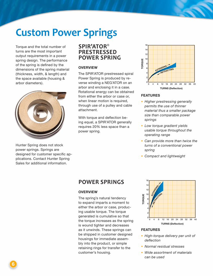
Custom power SpringsTorque and the total number of turns are the most important output requirements in a power spring design. The performance of the spring is defined by the dimensions of the spring material (thickness, width, & length) and the space available (housing & arbor diameters).
Hunter Spring does not stock power springs. Springs are designed for customer specific ap-plications. Contact Hunter Spring Sales for additional information.
SpIR’ATOR® pRESTRESSEd pOwER SpRINGoverview
The SPIR’ATOR prestressed spiral Power Spring is produced by re-verse winding a NEG’ATOR on an arbor and enclosing it in a case. Rotational energy can be obtained from either the arbor or case or, when linear motion is required, through use of a pulley and cable attachment.
With torque and deflection be-ing equal, a SPIR’ATOR generally requires 20% less space than a power spring.
FeatureS
• Higherprestressinggenerallypermitstheuseofthinnermaterialthusasmallerpackagesizethancomparablepowersprings
• Lowtorquegradientyieldsusabletorquethroughouttheoperatingrange
• Canprovidemorethantwicetheturnsofaconventionalpowerspring
• Compactandlightweight
TURNS (Deflection)
TO
RQ
UE
16
14
12
10
8
6
4
2
00 4 8 12 16 20 24 28 32 36 40
pOwER SpRINGSoverview
The spring’s natural tendency to expand imparts a moment to either the arbor or case, produc-ing usable torque. The torque generated is cumulative so that the torque increases as the spring is wound tighter and decreases as it unwinds. These springs can be shipped in customer designed housings for immediate assem-bly into the product, or simple retaining rings for transfer to the customer’s housing.
FeatureS
• High-torquedeliveryperunitofdeflection
• Normalresidualstresses
• Wideassortmentofmaterialscanbeused
TURNS (Deflection)
TO
RQ
UE
16
14
12
10
8
6
4
2
00 4 8 12 16 20 24 28 32 36 40
ENDS OF STOCK B MOTOR SPRINGS ARE FORMED AS "TONGUES" FOR MOUNTING
END DETAIL
INNER END
30° ±1°
W
BC
A
D3D4
D2D1
EF
S
T
OUTER END SYMBOLSw = MATERIAL WIDTHt = MATERIAL THICKNESSD3 = OUTPUT DRUM DIAMETERD2 = TAKE-UP DRUM DIAMETER
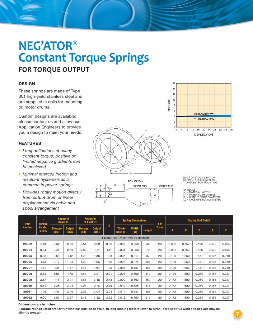
NEG’ATOR® Constant Torque SpringsFOR TORquE OuTpuT
Part Number
* TorqueLb.-In.±10%
Recom'd Drum Ø
Recom’d FLANgE Ø
S
Spring Dimensions# of
Turns
Spring End Detail
Storage(D2)
Output(D3)
Storage(D1)
Output(D4)
Thick-ness (T)
Width(W) Length A B C E F
FATIGUE LIFE - 2,500 CYCLES MINIMUM
20002 0.13 0.32 0.56 0.51 0.69 0.69 0.002 0.250 44 20 0.093 0.750 0.125 0.078 0.156
20004 0.34 0.51 0.89 0.82 1.11 1.11 0.004 0.250 70 20 0.093 0.750 0.125 0.078 0.156
20005 0.65 0.64 1.12 1.02 1.38 1.38 0.005 0.312 87 20 0.120 1.260 0.187 0.105 0.210
20006 1.13 0.77 1.34 1.23 1.66 1.66 0.006 0.375 106 20 0.120 1.260 0.187 0.105 0.210
20007 1.81 0.9 1.57 1.45 1.94 1.95 0.007 0.437 124 20 0.120 1.260 0.187 0.105 0.210
20008 2.65 1.03 1.78 1.64 2.21 2.21 0.008 0.500 144 20 0.120 1.500 0.250 0.156 0.317
20009 3.87 1.16 2.01 1.86 2.48 2.48 0.009 0.562 159 20 0.172 1.500 0.250 0.156 0.317
20010 5.50 1.28 2.23 2.04 2.76 2.76 0.010 0.625 175 20 0.172 1.500 0.250 0.156 0.317
20011 7.06 1.41 2.46 2.27 3.04 3.04 0.011 0.687 195 20 0.172 1.500 0.250 0.156 0.317
20012 9.00 1.53 2.67 2.45 3.32 3.32 0.012 0.750 210 20 0.172 1.500 0.250 0.156 0.317
Dimensions are in inches.
* torque ratings listed are for “unwinding” portion of cycle. in long running motors (over 15 turns), torque at full wind end of cycle may be slightly greater.
DeFlection
to
rq
ue
16
14
12
10
8
6
4
2
00 4 8 12 16 20 24 28 32 36 40
7
DeSign
These springs are made of Type 301 high-yield stainless steel and are supplied in coils for mounting on motor drums.
Custom designs are available; please contact us and allow our Application Engineers to provide you a design to meet your needs.
FeatureS
• Longdeflectionsatnearlyconstanttorque;positiveorlimitednegativegradientscanbeachieved
• Minimalintercoilfrictionandresultanthysteresisasiscommoninpowersprings
• Providesrotarymotiondirectlyfromoutputdrumorlineardisplacementviacableandspoolarrangement

1.0
.5
.5
.25
.625
1.625
3.75
2.5
.25 TYP
.50 1.38
.41
2.0
Ø.1774 MOUNTING HOLES
.88
1.19
2.5
2.0
Ø.1774 MOUNTING HOLES
.25 TYP
.41
3.75
.50 1.38
.88 1.19
8
NEG’ATOR® Motor AssembliesNEG’ATOR Spring Motor assem-blies are composed of a single spring mounted on a storage drum and mounted either singularly or in pairs to an output drum with an integral cable. The entire assembly is mounted on a base plate.
rigHt onlyMl-2919Ml-2920Ml-2921
rigHt onlyMl-1448
rigHt onlyMl-2917Ml-2918
Diagrams are shown in “right” configurations.
COMPONENT ML-1448 ML-2900 Series ML-2400 Series
Base Stainless steel Zinc-plated steel Zinc-plated steel
Drums Nylon Acetal (POM) Acetal (POM)
SpringType 301 high-yield
stainless steelType 301 high-yield
stainless steelType 301 high-yield
stainless steel
CableØ.015" nylon
monofilament (15 lb. test)Ø.024" uncoated
stainless steelØ.031" 3x7 high-yield galv. steel aircraft
cable coated to Ø.047" with nylon

5.28
1.88 2.25
2.75
2.25
.25 Ø.18 ±.003 6 MOUNTING HOLES .56
.445
2.25 1.88
6.25
2.56 2.75
3.25
2.75
.25 Ø.18 ±.003 6 MOUNTING HOLES .56
.38
2.25
1.88
9
rigHtMl-2476 Ml-2478Ml-2480
leFtMl-2477 Ml-2479Ml-2481
rigHtMl-2482Ml-2484Ml-2486Ml-2488Ml-2490Ml-2492
leFtMl-2483Ml-2485Ml-2487Ml-2489Ml-2491Ml-2493
Part Number
Spec Number
Cable Tension (lbs)
Length (in)
No. of Turns
Fatigue Life (min) Cable Type
Ml-1448 196560 0.375 36 20 3,000 Ø.015" nylon monofilament (15 lb. test)
Ml-2917 196565 1.0 72 15 7,500 Ø.024" uncoated stainless steel
Ml-2918 196570 2.0 72 15 2,500 Ø.024" uncoated stainless steel
Ml-2919 196575 3.0 72 15 4,500 Ø.024" uncoated stainless steel
Ml-2492 193280 3.1 273 45 15,000 Ø.031" 3x7 high-yield galv. steel aircraft cable coated to Ø.047" with nylon
Ml-2920 196580 4.0 72 15 2,500 Ø.024" uncoated stainless steel
Ml-2490 193275 5.0 235 40 9,000 Ø.031" 3x7 high-yield galv. steel aircraft cable coated to Ø.047" with nylon
Ml-2921 196585 5.0 72 15 2,000 Ø.031" 3x7 high-yield galv. steel aircraft cable coated to Ø.047" with nylon
Ml-2476 193225 7.5 42 8 6,000 Ø.031" 3x7 high-yield galv. steel aircraft cable coated to Ø.047" with nylon
Ml-2488 193270 7.5 207 36 6,000 Ø.031" 3x7 high-yield galv. steel aircraft cable coated to Ø.047" with nylon
Ml-2478 193230 10.0 37 7 5,000 Ø.031" 3x7 high-yield galv. steel aircraft cable coated to Ø.047" with nylon
Ml-2486 193260 10.0 184 33 4,000 Ø.031" 3x7 high-yield galv. steel aircraft cable coated to Ø.047" with nylon
Ml-2484 193250 13.5 160 29 2,500 Ø.031" 3x7 high-yield galv. steel aircraft cable coated to Ø.047" with nylon
Ml-2480 193235 15.0 33 6 2,500 Ø.031" 3x7 high-yield galv. steel aircraft cable coated to Ø.047" with nylon
Ml-2482 193242 15.0 160 29 2,000 Ø.031" 3x7 high-yield galv. steel aircraft cable coated to Ø.047" with nylon
Diagrams are shown in “right” configurations.
10
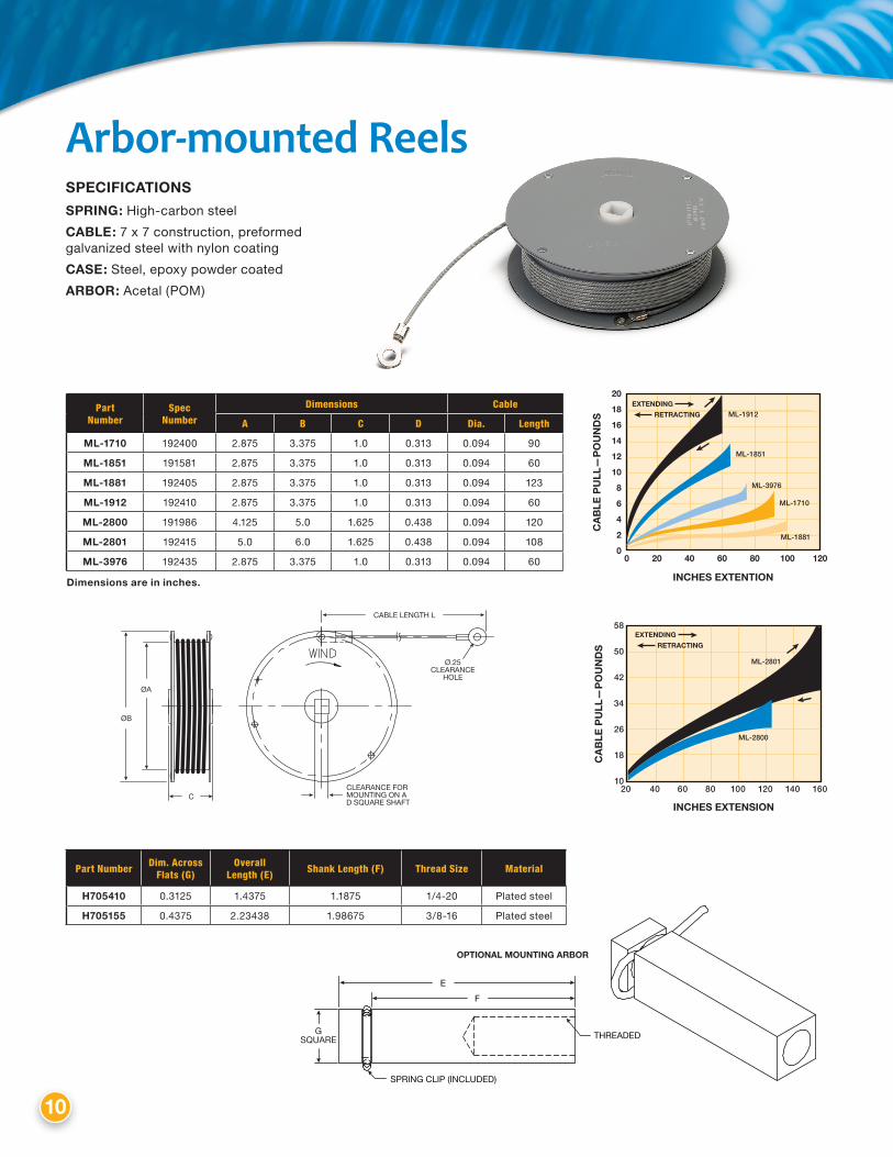
Arbor-mounted Reels
CABLE LENGTH L
ØA
ØB
CCLEARANCE FOR MOUNTING ON A D SQUARE SHAFT
Ø.25 CLEARANCE
HOLE
20
18
16
14
12
10
8
6
4
2
00 20 40 60 80 100 120
incHeS eXtention
ca
Ble
pu
ll—
po
un
DS
eXtenDing
retracting ML-1912
ML-1851
ML-3976
ML-1710
ML-1881
incHeS eXtenSion
ca
Ble
pu
ll—
po
un
DS
58
50
42
34
26
18
1020 40 60 80 100 120 140 160
eXtenDing
retracting
ML-2801
ML-2800
SpeciFicationS
Spring: High-carbon steel
caBle: 7 x 7 construction, preformed galvanized steel with nylon coating
caSe: Steel, epoxy powder coated
arBor: Acetal (POM)
Part Number
Spec Number
Dimensions Cable
A B C D Dia. Length
Ml-1710 192400 2.875 3.375 1.0 0.313 0.094 90
Ml-1851 191581 2.875 3.375 1.0 0.313 0.094 60
Ml-1881 192405 2.875 3.375 1.0 0.313 0.094 123
Ml-1912 192410 2.875 3.375 1.0 0.313 0.094 60
Ml-2800 191986 4.125 5.0 1.625 0.438 0.094 120
Ml-2801 192415 5.0 6.0 1.625 0.438 0.094 108
Ml-3976 192435 2.875 3.375 1.0 0.313 0.094 60
Part Number Dim. Across Flats (g)
Overall Length (E) Shank Length (F) Thread Size Material
H705410 0.3125 1.4375 1.1875 1/4-20 Plated steel
H705155 0.4375 2.23438 1.98675 3/8-16 Plated steel
Dimensions are in inches.
E
SPRING CLIP (INCLUDED)
THREADED
F
G SQUARE
OPTIONAL MOUNTING ARBOR

11
Part Number Spec Number Length
Ml-3949 192430 42"
Ml-3946 192425 52"
Ml-3943 192420 84"
Ml-1565* 191606 64"
.702
.125
2.0
1.5
.25
.25
2.38
1.88
2X Ø.238
.44
.25
.25
CLEARANCE HOLE FOR #10 STUD
CL.44 TO OF CABLE
plastic Spring-powered ReelsThe ML-4575 series utilizes the SPIR’ATOR prestressed power spring. The closed case con-struction makes the spring unit tamper-proof when mounted.
Ring terminal provides customer the ability to secure cables with Velcro®, tie wraps, zip ties, etc. for many cable management applications.
CL
CL
2.0
.25
.25
2.375
1.75 2X Ø.238
1.88
.563
.048 .845
.563
INCHES DEFLECTION
CA
BLE
PU
LL—
PO
UN
DS
3.0
2.5
2.0
1.5
1.0
.5
00 8 16 24 32 40 48 56 64 72
EXTENDING
RETRACTING
ML-3949
ML-3946
ML-1565
ML-3943
Spring: Type 301 stainless steel SPIR’ATOR spring
caBle: .024" diameter 7x3 stainless steel
BaSe: Steel, zinc coated
DruM: stainless steel
Base-mounted Reels
FeatureS
• Compact
• Lightweight
• Stainlesssteelcable
• Cableavailableeithercoatedto.024"oruncoatedto.018"
• Customterminationsavailable
* nylon coated cable to .034" diameter.
Part Number Spec Number Cable Length Force
Ml-4575-1 190515 42" (coated) 2.0 lb
Ml-4575-2 190520 52" (coated) 1.5 lb
Ml-4575-3 190525 64" (coated) 1.0 lb
Ml-4575-4 190530 84" (coated) 0.5 lb
Ml-4575-5 198266 27" (coated) 3.0 lb
Ml-4575-10 198367 42" (uncoated) 2.0 lb
Ml-4575-11 198368 52" (uncoated) 1.5 lb
Ml-4575-12 198369 64" (uncoated) 1.0 lb
Ml-4575-13 198370 84" (uncoated) 0.5 lb
820 Pennsylvania Blvd. • Feasterville, PA 19053TEL: 215-355-6900 • FAX: 215-354-1801
www.ametekhunterspring.com
©2013, by AMETEK, Inc. All rights reserved. Printed in the U.S.A. 1M913PC (160176)
Due to the wide range of applications our products can be used in, aMeteK Hunter Spring cannot guarantee the accuracy of information or suitability of our product in any given situation due to factors beyond our control. users of our products should perform their own tests
to determine the suitability of the product for their particular purpose. Statements concerning the possible use of our products are not intended as recommendations to use our products in the infringement of any patent. Specifications subject to change without notice.
ISO 9001 REGISTEREDMANUFACTURER
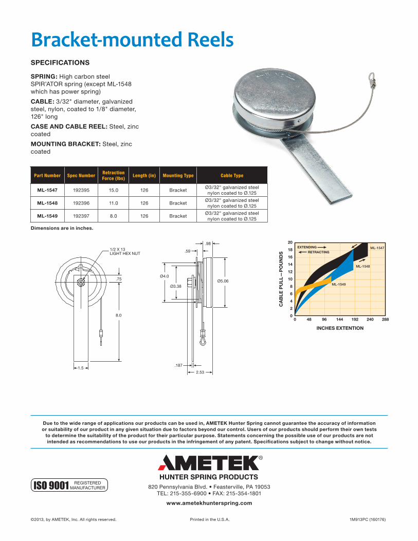
Bracket-mounted Reels
1.5
.75
8.0
1/2 X 13LIGHT HEX NUT
Ø5.06
.98
2.53
.187
.59
Ø3.38
Ø4.0
20
18
16
14
12
10
8
6
4
2
00 48 96 144 192 240 288
INCHES EXTENTION
CA
BLE
PU
LL—
PO
UN
DS
EXTENDING
RETRACTINGML-1547
ML-1548
ML-1549
SpeciFicationS
Spring: High carbon steel SPIR’ATOR spring (except ML-1548 which has power spring)
caBle: 3/32" diameter, galvanized steel, nylon, coated to 1/8" diameter, 126" long
caSe anD caBle reel: Steel, zinc coated
Mounting BracKet: Steel, zinc coated
Part Number Spec Number Retraction Force (lbs) Length (in) Mounting Type Cable Type
Ml-1547 192395 15.0 126 BracketØ3/32" galvanized steel nylon coated to Ø.125
Ml-1548 192396 11.0 126 BracketØ3/32" galvanized steel nylon coated to Ø.125
Ml-1549 192397 8.0 126 BracketØ3/32" galvanized steel nylon coated to Ø.125
Dimensions are in inches.


