TRANSPORTATION RESEARCH RECORD 1427 47 Stone Mastic Asphalt Trials in Ontario JOHN J. EMERY, WALTER SCHENK, JOHN J. CARRICK, J. KEITH DAVIDSON, W. KEITH MACINNIS, AND GERHARD J. A. KENNEPOHL Stone mastic asphalt (SMA) use in Europe (split mastic in Ger- many) and Japan, because of excellent frictional properties, plas- tic deformation resistance, fatigue endurance, and durability, formed the basis for 1990 and 1991 technology transfer demon- stration trials. This SMA work incorporated international expe- rience using local aggregates, fillers, engineered asphalt cements, and fibers. SMA is a gap-graded, dense, hot-mix asphalt with a large proportion of coarse aggregate (passing 2 mm limited to about 20 percent, all crushed material) and a rich asphalt cement/ filler mastic. The coarse aggregate forms a high-stability structural matrix. The engineered asphalt cement, fine aggregate, filler, and stabilization additive (typically fiber) form a mastic that binds the structural matrix together. Plant and placement trials of two pre- liminary SMA designs incorporating fly ash filler and fiber in- dicated no transportation, placement, or compaction problems, but care must be taken to ensure proper mixing of any fiber added. From this demonstration work, SMA-modified Marshall mix design procedures were developed and four highway trial sections completed in 1991. Quality assurance testing indicated no significant problems in meeting SMA mix design requirements once production parameters were established. Monitoring and characterization of these SMA pavements are in progress, with very favorable rutting resistance and surface texture performance shown. Because of the growing use of stone mastic asphalt (SMA) in Europe and Japan and the obvious technology transfer ap- plicability to Canada for both climate and pavement perfor- mance requirements, an SMA research and development team approach was used to quickly complete demonstration SMA trial sections in December 1990, the first in North America. This initial satisfactory SMA demonstration work was ex- tended to SMA l)ighway trial sections in June and October 1991, assisted by the Ontario Ministry of Transportation (MTO). The use of SMA in Europe and Japan is based on demonstrated excellent frictional properties, plastic defor- mation (rutting) resistance, fatigue endurance, and durability. The team's SMA work incorporated international SMA de- sign and construction experience using locally available ag- gregates, fillers, engineered asphalt cements, and fibers in conventional hot-mix plants. J. J. Emery and W. Schenk, John Emery Geotechnical Engineering Ltd., 109 Woodbine Downs Boulevard, No. 1, Etobicoke, Ontario, Canada M9W 6Yl. J. J. Carrick, J. K. Davidson, and W. K. Macinnis, McAsphalt Industries Ltd., 8800 Sheppard Avenue East, West Hill, Ontario, Canada MlB 5R4. G. J. A. Kennepohl, Pavements and Roadway Office, Research and Development Branch, Ontario Min- istry of Transportation, 1201 Wilson Avenue, Downsview, Ontario, Canada M3M 1J8. SMA What is SMA and why is it getting so much attention from North American pavement experts (J-5)? SMA (termed "split mastic" in Germany, where it was developed and has been used for about 20 years) is a gap-graded, dense (about 3 percent air voids mix design), hot-mix asphalt (HMA) with a large proportion of coarse aggregate (passing 2 mm limited to about 20 percent, all aggregate 100 percent crushed) and a rich asphalt cement/filler mastic (about 10 percent minus 75 μm) (6,7). The coarse aggregate, through point-to-point con- tact as shown in Figure 1, forms a high stability skeleton (structural matrix) with good internal friction and aggregate interlock to resist load-induced shear. A typical SMA grading band, compared with conventional HMA, is shown in Figure 2, with further details on typical SMA aggregates and filler compositions. The asphalt cement (typically polymer-modified), fine ag- gregate, filler, and stabilization additive (if necessary, typi- cally about 0.3 percent mineral, glass, or cellulosic fiber to prevent asphalt cement runoff) form a mastic that binds the structural matrix together. The polymer-modified asphalt ce- ment content is typically 1.0 to 1.5 percent greater than for a conventional HMA incorporating the same aggregates. This rich, durable mastic has a far higher ratio of filler (finer than 90 μm) to asphalt cement content than the limit of 1.2 rec- ommended by FHW A for conventional dense-graded HMA (8). The high-stability skeleton of SMA must contain all the mastic binder while maintaining the point-to-point contacts (Figure 1) essential for shear deformation (rutting) resistance. SMA is usually designed to have an air voids content of 3 percent. Too much mastic will push the coarse aggregate par- ticles apart with a drastic reduction in pavement shear de- formation resistance, and too little mastic will result in high air voids with reduced pavement durability caused by accel- erated aging and moisture damage (6,7). Obviously, there is little latitude during SMA production in the mix design, ag- gregate gradation, polymer-modified asphalt cement content, or fiber content. The SMA typical mix design [50-blow Marshall method often used (9-11)] air voids content of 3 percent provides an in-place air voids content of less than 6 percent with appro- priate compaction. Static steel-wheel compaction is generally used, primarily to orient the coarse aggregate particles at the pavement surface, and there is little additional roller densi- fication or deformation. To avoid coarse aggregate fracture, vibratory rolling is not used in Europe, and to avoid possible mastic surface flushing, pneumatic rolling is not used. Vibra- tory rolling was used on part of the last SMA trial and has been used on several trial sections in the United States. Be-
Transcript
TRANSPORTATION RESEARCH RECORD 1427 47
Stone Mastic Asphalt Trials in Ontario
JOHN J. EMERY, WALTER SCHENK, JOHN J. CARRICK, J. KEITH DAVIDSON,
W. KEITH MACINNIS, AND GERHARD J. A. KENNEPOHL
Stone mastic asphalt (SMA) use in Europe (split mastic in Germany) and Japan, because of excellent frictional properties, plastic deformation resistance, fatigue endurance, and durability, formed the basis for 1990 and 1991 technology transfer demonstration trials. This SMA work incorporated international experience using local aggregates, fillers, engineered asphalt cements, and fibers. SMA is a gap-graded, dense, hot-mix asphalt with a large proportion of coarse aggregate (passing 2 mm limited to about 20 percent, all crushed material) and a rich asphalt cement/ filler mastic. The coarse aggregate forms a high-stability structural matrix. The engineered asphalt cement, fine aggregate, filler, and stabilization additive (typically fiber) form a mastic that binds the structural matrix together. Plant and placement trials of two preliminary SMA designs incorporating fly ash filler and fiber indicated no transportation, placement, or compaction problems, but care must be taken to ensure proper mixing of any fiber added. From this demonstration work, SMA-modified Marshall mix design procedures were developed and four highway trial sections completed in 1991. Quality assurance testing indicated no significant problems in meeting SMA mix design requirements once production parameters were established. Monitoring and characterization of these SMA pavements are in progress, with very favorable rutting resistance and surface texture performance shown.
Because of the growing use of stone mastic asphalt (SMA) in Europe and Japan and the obvious technology transfer applicability to Canada for both climate and pavement performance requirements, an SMA research and development team approach was used to quickly complete demonstration SMA trial sections in December 1990, the first in North America. This initial satisfactory SMA demonstration work was extended to SMA l)ighway trial sections in June and October 1991, assisted by the Ontario Ministry of Transportation (MTO). The use of SMA in Europe and Japan is based on demonstrated excellent frictional properties, plastic deformation (rutting) resistance, fatigue endurance, and durability. The team's SMA work incorporated international SMA design and construction experience using locally available aggregates, fillers, engineered asphalt cements, and fibers in conventional hot-mix plants.
J. J. Emery and W. Schenk, John Emery Geotechnical Engineering Ltd., 109 Woodbine Downs Boulevard, No. 1, Etobicoke, Ontario, Canada M9W 6Yl. J. J. Carrick, J. K. Davidson, and W. K. Macinnis, McAsphalt Industries Ltd., 8800 Sheppard Avenue East, West Hill, Ontario, Canada MlB 5R4. G. J. A. Kennepohl, Pavements and Roadway Office, Research and Development Branch, Ontario Ministry of Transportation, 1201 Wilson Avenue, Downsview, Ontario, Canada M3M 1J8.
SMA
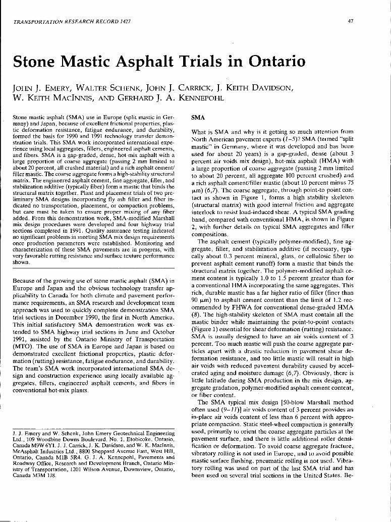
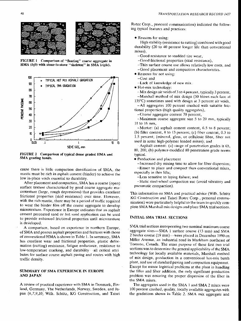
What is SMA and why is it getting so much attention from North American pavement experts (J-5)? SMA (termed "split mastic" in Germany, where it was developed and has been used for about 20 years) is a gap-graded, dense (about 3 percent air voids mix design), hot-mix asphalt (HMA) with a large proportion of coarse aggregate (passing 2 mm limited to about 20 percent, all aggregate 100 percent crushed) and a rich asphalt cement/filler mastic (about 10 percent minus 75 µm) (6,7). The coarse aggregate, through point-to-point contact as shown in Figure 1, forms a high stability skeleton (structural matrix) with good internal friction and aggregate interlock to resist load-induced shear. A typical SMA grading band, compared with conventional HMA, is shown in Figure 2, with further details on typical SMA aggregates and filler compositions.
The asphalt cement (typically polymer-modified), fine aggregate, filler, and stabilization additive (if necessary, typically about 0.3 percent mineral, glass, or cellulosic fiber to prevent asphalt cement runoff) form a mastic that binds the structural matrix together. The polymer-modified asphalt cement content is typically 1.0 to 1.5 percent greater than for a conventional HMA incorporating the same aggregates. This rich, durable mastic has a far higher ratio of filler (finer than 90 µm) to asphalt cement content than the limit of 1.2 recommended by FHW A for conventional dense-graded HMA (8). The high-stability skeleton of SMA must contain all the mastic binder while maintaining the point-to-point contacts (Figure 1) essential for shear deformation (rutting) resistance. SMA is usually designed to have an air voids content of 3 percent. Too much mastic will push the coarse aggregate particles apart with a drastic reduction in pavement shear deformation resistance, and too little mastic will result in high air voids with reduced pavement durability caused by accelerated aging and moisture damage (6,7). Obviously, there is little latitude during SMA production in the mix design, aggregate gradation, polymer-modified asphalt cement content, or fiber content.
The SMA typical mix design [50-blow Marshall method often used (9-11)] air voids content of 3 percent provides an in-place air voids content of less than 6 percent with appropriate compaction. Static steel-wheel compaction is generally used, primarily to orient the coarse aggregate particles at the pavement surface, and there is little additional roller densification or deformation. To avoid coarse aggregate fracture, vibratory rolling is not used in Europe, and to avoid possible mastic surface flushing, pneumatic rolling is not used. Vibratory rolling was used on part of the last SMA trial and has been used on several trial sections in the United States. Be-
48
FIGURE 1 Comparison of "floating" coarse aggregate in HMA (left) with stone-to-stone "skeleton" in SMA (right).
DO o lYPIOl I-OT MIX ~T GW:\t\Tla-l
90 • TYPIOl ~ GW:JATIOO
BO
70
~ 60 V')
if 50 !Z
~ 40 ~
30
20
'()
0 a.as .1 1 {)
SIEVE SIZE. mm
FIGURE 2 Comparison of typical dense graded HMA and SMA grading bands.
15
cause there is little compaction densification of SMA, the mastic must be rich in asphalt cement (binder) to achieve the low in-place voids essential to durability.
After placement and compaction, SMA has a coarse (open) surface texture characterized by good coarse aggregate macrotexture (large, rough depressions) that provides excellent frictional properties (skid resistance) over time. However, with the rich mastic, there may be a period of traffic required to wear the binder film off the coarse aggregate to develop microtexture. Experience in Europe indicates that an asphalt cement precoated sand or hot sand application can be used to provide enhanced frictional properties until microtexture is developed.
A comparison, based on experience in northern Europe, of SMA and porous asphalt properties and features with those of conventional HMA is shown in Table 1. In summary, SMA has excellent wear and frictional properties, plastic deformation (rutting) resistance, fatigue endurance, resistance to low-temperature cracking, and durability-all critical attributes for surface course asphalt paving and routes with high traffic density.
SUMMARY OF SMA EXPERIENCE IN EUROPE AND JAPAN
A review of practical experience with SMA in Denmark, Finland, Germany, The Netherlands, Norway, Sweden, and Japan (6,7,9,10; Wilh. Schiltz, KG Construction, and Taisei
TRANSPORTATION RESEARCH RECORD 1427
Rotec Corp., personal communication) indicated the following typical features and practices:
•Reasons for using: -High stability (resistance to rutting) combined with good
durability (20 to 40 percent longer life than conventional mixes),
-Good resistance to studded tire wear, -Good frictional properties (skid resistance), - Thin surface course use allows relatively low costs, and -Good placement and compaction characteristics.
• Reasons for not using: -Cost and -Lack of knowledge of new mix.
• Hot-mix technology: -Mix design air voids of 3 to 4 percent, typically 3 percent, -Marshall method of mix design (50 blows each face at
135°C) sometimes used with design at 3 percent air voids, -All aggregates 100 percent crushed with suitable fric
tional properties (high-quality aggregates), -Coarse· aggregate content 70 percent, -Maximum coarse aggregate size 5 to 20 mm, typically
11to16 mm, -Mortar: (a) asphalt cement content, 6.5 to 8 percent;
(b) filler content, 8 to 13 percent; (c) fiber content, 0.3 to 1.5 percent; (mineral, glass, or cellulosic fiber, fiber not used in some high-polymer loaded mixes); and
-Asphalt cement: (a) range of penetration grades is 65, 80, 200; (b) polymer-modified 80 penetration grade seems typical. • Production and placement
-Increased dry mixing time to allow for fiber dispersion; -Easier to place and compact than conventional mixes,
especially in thin lifts; -Less sensitive to laying failure; and -Static steel-wheel compaction use (avoid vibratory and
pneumatic compaction).
This information on SMA and practical advice (Wilh. Schiltz KG Construction and Taisei Rotec Corp., personal communication) were particularly helpful to the team to quickly complete SMA Marshall mix designs and place SMA trial sections.
INITIAL SMA TRIAL SECTIONS
SMA trial sections incorporating two nominal maximum coarse aggregate sizes-SMA 1 surface course (13 mm) and SMA 2 binder course (19 mm)-were placed in December 1990 on Miller Avenue, an industrial road in Markham northeast of Toronto, Canada. The main purpose of these first two trial sections was to determine the general applicability of the SMA technology for locally available materials, Marshall method of mix design, production in a conventional hot-mix batch plant, and use of standard paving and compaction equipment. Except for minor logistical problems at the plant in handling the filler and fiber addition, the only significant production problem was ensuring the proper dispersion of the fiber in the ·sMA mixes.
The aggregates used in the SMA 1 and SMA 2 mixes were 100 percent crushed, quality, locally available aggregates with the gradations shown in Table 2. SMA mix aggregate and
Emery et al.
TABLE 1 Ranking of SMA Compared with HMA (7)
PROPERTY OR FEATURE SMA COMPARED TO HMA
Shear Resistance Much Better
Abrasion Resistance Much Better
Durability Much Better
Load Distribution Equal/Worse
Cracking Resistance Better/Much Better
Skid Resistance Better
Water Spray Equal
Light Reflection Better
Noise Reduction Equal
Public Recognition Much Better
filler compositions were selected to give gradations based on typical grading bands (preliminary specifications) used in Germany (Table 2). Standard Marshall mix design procedures (11), using 75 blows per face, were followed. In some European countries 50 blows per face are used. At this early stage of SMA work there was concern about potential traffic densification effects so a higher laboratory compaction effort was used. The SMA 1 and SMA 2 mixes were designed at an asphalt cement content of about 3 percent air voids (Table 3). Although the designs were done with 60/70-penetration
49
(Styrelf) polymer-modified asphalt cement, the late season paving work used still-available conventional 85/100-penetration-grade asphalt cement.
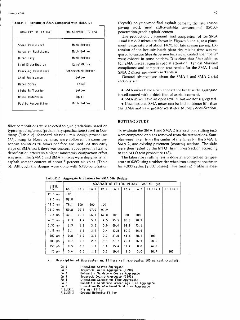
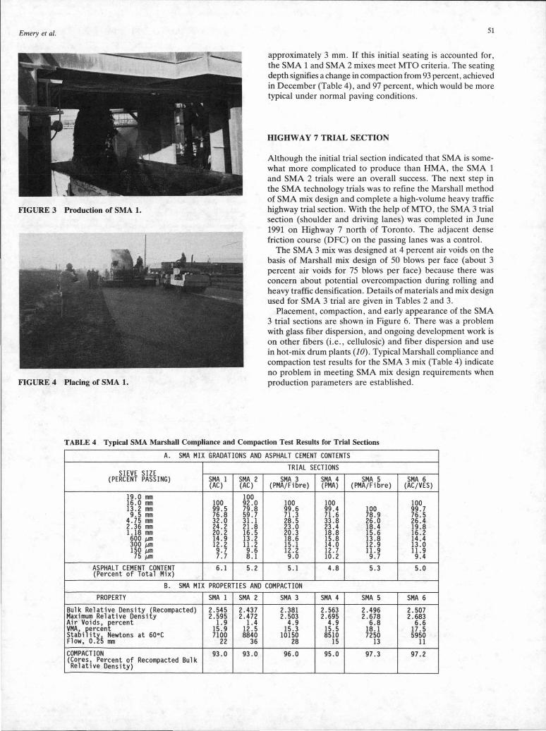
The production, placement, and compaction of the SMA 1 and SMA 2 mixes are shown in Figures 3 and 4, at a placement temperature of about 140°C for late season paving. Extension of the hot-mix batch plant dry mixing time was required to ensure fiber dispersion because uncoated fiber "balls" were evident in some batches. It is clear that fiber addition for SMA mixes requires special attention. Typical Marshall compliance and compaction test results for the SMA 1 and SMA 2 mixes are shown in Table 4.
General observations about the SMA 1 and SMA 2 trial sections are
• SMA mixes have a rich appearance because the aggregate is well-coated with a thick film of asphalt cement.
• SMA mixes have an open texture but are not segregated. • Uncompacted SMA mixes can be laid in thinner lifts than
can HMA and have greater resistance to roller densification.
RUTTING STUDY
To evaluate the SMA 1 and SMA 2 trial sections, rutting tests were completed on slabs removed from the test sections. Samples were taken from the center of the lanes for the SMA 1, SMA 2, and existing pavement (control) sections. The slabs were then tested by the MTO Bituminous Section according to the MTO test procedure (12).
The laboratory rutting test is done at a controlled temperature of 60°C using a rubber-tire wheel run along the specimen for 4,000 cycles (8,000 passes). The final rut profile is mea-
TABLE 2 Aggregate Gradations for SMA Mix Designs
SIEVE AGGREGATE OR FILLER, PERCENT PASSING (a)
SIZE CA 1 CA 2 CA 3 CA 4 FA 1 FA 2 FA 3 FILLER 1 FILLER 2 26.5 mm 100
19.0 mm 92.8
16.0 mm 78.1 100 100 100 13.2 mm 59.8 99.5 97.9 99.9 9.5 mm 32 .1 75.6 66.1 67.0 100 100 100
4.75 mm 2.3 4.2 5.3 4.5 95.5 90.7 98.9 2. 36 mm 1.3 1. 2 3.5 0.5 66.4 63.8 73.l 1.18 mm 1.1 1.1 3.4 0.4 43.8 50.3 46.6
sured and the average rut depth in millimeters is determined. The temperature is maintained throughout the 2 hr test by using a temperature-controlled water bath and infrared lamps. The specimens are measured across the rut in three places at various stages of the rutting cycles, and the average rut depth is obtained. The rut depth with number of passes for SMA 1, SMA 2, and control tests are shown in Figure 5. MTO has tentatively set a maximum allowable rut depth of 3.5 mm as
SMA 1
2.445
2.530
3.4
19.0
9700
25+
SMA 2 SMA 3 SMA 4 SMA 5 SMA 6
2.424 2.372 2.582 2.574 2.597
2.491 2.471 2.668 2.653 2.678
2.7 4.0 3.2 3.0 3.0
15.6 15.8 15.1 15.8 14.4
13700 8600 7880 8140 7170
25+ 25+ 23 25 16
the standard for rut resistant mixes. The test data on the three slabs tested indicate the following values: 5.1 mm for SMA 1, 6. 7 mm for SMA 2, and 16.8 mm for control.
On the basis of the test data in Figure 5, it appears that there was an initial seating of the SMA 1 and SMA 2 specimens before true rutting occurred under the wheel loading. The plots for both SMA 1 (surface mix) and SMA 2 (binder mix) show that there appears to have been a seating depth of
Emery et al. 51
approximately 3 mm. If this initial seating is accounted for , the SMA 1 and SMA 2 mixes meet MTO criteria. The seating depth signifies a change in compaction from 93 percent, achieved in December (Table 4) , and 97 percent, which would be more typical under normal paving conditions.
HIGHWAY 7 TRIAL SECTION
FIGURE 3 Production of SMA 1.
Although the initial trial section indicated that SMA is somewhat more complicated to produce than HMA , the SMA 1 and SMA 2 trials were an overall success. The next step in the SMA technology trials was to refine the Marshall method of SMA mix design and complete a high-volume heavy traffic highway trial section. With the help of MTO , the SMA 3 trial section (shoulder and driving lanes) was completed in June 1991 on Highway 7 north of Toronto. The adjacent dense friction course (DFC) on the passing lanes was a control.
FIGURE 4 Placing of SMA 1.
The SMA 3 mix was designed at 4 percent air voids on the basis of Marshall mix design of 50 blows per face (about 3 percent air voids for 75 blows per face) because there was concern about potential overcompaction during rolling and heavy traffic densification. Details of materials and mix design used for SMA 3 trial are given in Tables 2 and 3.
Placement, compaction , and early appearance of the SMA 3 trial sections are shown in Figure 6. There was a problem with glass fiber dispersion , and ongoing development work is on other fibers (i .e. , cellulosic) and fiber dispersion and use in hot-mix drum plants (JO). Typical Marshall compliance and compaction test results for the SMA 3 mix (Table 4) indicate no problem in meeting SMA mix design requirements when production parameters are established.
TABLE 4 Typical SMA Marshall Compliance and Compaction Test Results for Trial Sections
A. SMA MIX GRADATIONS AND ASPHALT CEMENT CONTENTS
TRIAL SECTIONS SIEVE SIZE
(PERCENT PASSING) SMA 1 SMA 2 SMA 3 SMA 4 SMA 5 SMA 6 (AC) (AC) (PMA/Fibre) (PMA) (PMA/Fibre) (AC/VES)
19.0 mm 100 16.0 mm 100 92.0 100 100 100 13.2 mm 99.5 79.8 99.6 99.4 100 99.7 9.5 mm 76.8 59.7 71.3 71.6 78.9 76.5
The early, and 1-year, performance of the SMA 3 trial section on Highway 7 has been excellent (Figures 7 and 8). There has been no significant tightening of the SMA 3 coarse (open) surface texture, which indicates good resistance to heavy traffic densification. Test cores and slabs (Figure 9) were taken from the trial section for standard testing and MTO wheel tracking (rutting) tests (12). The rut depth for the SMA 3 wheel tracking tests (average for two slabs, 60°C, 4,000 cycles) was only 2.6 mm, as compared with 5.0 mm for the conventional DFC control, and lower than the MTO's tentative allowed maximum of 3.5 mm as the standard for rut resistant mixes. This rutting resistance is excellent and provides comparative confirmation of this important characteristic of SMA mixes.
HIGHWAY 404 RAMPS TRIAL SECTIONS
Three further SMA highway trial sections were completed on ramps to Highway 404 (at Regional Highway 16 near Buttonville north of Toronto) in October 1991. Because of the satisfactory compaction achieved with the SMA 3 trial section , apparent lack of traffic densification, and current German SMA mix design experience (0. Schiltz and J . Scherocman ,
RUT DEPTH in mm 18 -
..---------~
16 - SAMPLES
-e- SMA l (SURFACE) 14 - ~ SMA 2 (BINDER)
12 - ~ BMA (CONTROL)
IO-
8-
6 -
4- --·
0 500 1000 3000 3000 4000 5000 6000 7000 8000
#OF PASSES
FIGURE 5 Rutting test results for SMA 1, SMA 2, and HMA pavement samples.
FIGURE 6 Placing of SMA 3. Note coarse surface texture on right compared with DFC on left.
TRANSPORTATION RESEARCH RECORD 1427
Wilh. Schiltz KG Construction , personal communication) , a standard SMA Marshall mix design with 50 blows per face at 135°C and design air voids of 3 percent was adopted for these trial sections. Details of the materials and mix designs used for the SMA 4, SMA 5, and-SMA 6 trial sections (Tables 2 and 3) can be summarized as
• SMA 4: polymer-modified asphalt cement (Styrelf 60170) , • SMA 5: polymer-modified asphalt cement and Arbocel
cellulosic fiber , and
FIGURE 7 Appearance of SMA 3 test section, right, after 5 weeks of heavy traffic compared with DFC passing lane on left.
FIGURE 8 Close-up of SMA 3 after 1 year, with no evidence of tightening or deformation.
FIGURE 9 Test slab from SMA 3 test section. Note stone-tostone skeleton in surface course.
Emery et al.
• SMA 6: 7 percent Vestoplast added as percentage of asphalt cement (85/100).
The mix designs (Table 3) had very close results (Wilh. Schutz KG Construction, personal communication).
The SMA 4, SMA 5, and SMA 6 trial sections were placed late in the 1991 paving season (October 28, ambient temperature 8°C to 11°C). There were initial problems with low SMA 4 mix temperatures, relatively low mix temperature adopted (135°C) for Styrelf 60/70 and significant mixing temperature decrease with filler addition cooling, that resulted in some incompletely melted filler poly-melt bags. These problems were rectified and subsequent mixing, placement, and compaction of the SMA mixes proceeded satisfactorily. Although the 135°C may be satisfactory for Vestoplast (SMA 6), it is clear that higher temperatures are necessary for polymermodified asphalt cements such as Styrelf 60/70 (about 150°C for SMA 4 and SMA 5) in accordance with each supplier's recommendations.
Typical Marshall compliance and compaction test results for the mixes in Table 4 indicate somewhat high air voids, particularly for SMA 5 and SMA 6. Cores taken from these trial sections show that the traprock coarse aggregate used for the mixes contained more flat and elongated particles than during the mix designs, which tend to "bridge" (bulk) in the mix, particularly at lower compaction temperatures. Vibratory compaction was used for some of SMA 6, to gain placement experience, with no apparent improvement in compaction but some coarse aggregate breakage.
CURRENT SMA ACTIVITIES
All seven trial sections are being monitored along with conventional control mixes, with emphasis on SMA 3, SMA 4, SMA 5, and SMA 6 rather than DFC. This will involve testing in the field (densification, transverse profile, and frictional properties) and the laboratory (wheel tracking and performance properties characterization). The team has installed a Nottingham asphalt tester, which permits the measurement of elastic stiffness (resilient modulus) using the repeated load indirect tension test, resistance to permanent resistance using the uniaxial creep or repeated load axial test, and fatigue endurance using repeated tension loading (13-16). This SMA characterization is critical to developing the deformation resistance, fatigue endurance, and durability of SMA mixes. Such full asphalt concrete characterization was also the focus of Strategic Highway Research Program activities (15). Because the structural matrix of SMA mixes is critical to performance, volumetric methods of optimizing the aggregates selection were also investigated (17).
CONCLUSIONS
Although the Ontario technology transfer of SMA (focusing on SMA characterization) is still in progress, the trial section results to date must be considered a success (18). SMA work, along with current U.S. SMA test sections, should quickly provide the technical and practical basis for regular SMA use in Ontario.
53
ACKNOWLEDGMENTS
SMA mix design and production information provided by Masahiko Ishitani, Taisei Rotec Corp., and Ottmar Schutz, Wilh. Schutz KG Construction, was particularly helpful in the SMA technology transfer to Ontario. The continuing logistical and technical support of MTO is gratefully acknowledged. The assistance of Johanna Ernyes, McAsphalt Engineering Services, is also gratefully acknowledged. McAsphalt Industries Ltd., Miller Paving Ltd., and John Emery Geotechnical Engineering Ltd. make up the SMA research and development team.
REFERENCES
1. Kuennen, T. "Split Mastic" Asphalt-Next Overseas Import? Roads and Bridges, Vol. 29, No. 1, Jan. 1991, p. 48.
2. Muri, W. Paving the Way. TR News, No. 154, May-June 1991, p. 2.,
3. Emery, J. J. Stone Mastic Asphalt-Ontario Looks Closer at New High-Performance Pavement Mixes. Asphaltopics, Ontario Hot Mix Producers Association, Mississauga, Ontario, Canada, July 1991, p. 3.
4. U.S. Road Builders Look to Europe. Engineering News Record, Vol. 227, No. 6, Aug. 12, 1991, p. 8.
5. Stone Matrix Asphalt (SMA) Comes to U.S.-Placed by Four States this Year. Asphalt Technology News, Vol. 3, No. 2, National Center for Asphalt Technology, Auburn University, Auburn, Ala., Fall 1991, p. 1.
6. Stone Mastic Asphalt-SMA-Technology Synopsis and Work Plan. Draft. FHWA, U.S. Department of Transportation, Feb. 1991.
7. 1990 European Asphalt Study Tour. AASHTO, Washington, D.C., June 1991.
8. Bituminous Mix Design and Field Control. Technical Advisory T5040.24. FHW A, U.S. Department of Transportation, Aug. 1985.
9. Porous Asphalt and Stone Mastic Asphalt Surface Layers in the EAPA Countries. European Asphalt Pavement Association, Stockholm, Sweden, May 1989.
10. An Introduction to Stone Mastic Asphalt (SMA). ScanRoad, Waco, Tex., Jan. 1991.
11. Mix Design Methods for Asphalt Concrete and Other Hot-Mix Types. Manual Series 2. Asphalt Institute, Lexington, Ky., 1988.
12. Yacyshyn, R., K. K., Tam, and D. F. Lynch. Using a Wheel Tracking Machine for Evaluation of Asphalt Rutting. Report EM-93. Engineering Materials Office, Ontario Ministry of Transportation, Downsview, Ontario, Canada, Mar. 1989.
13. Brown, S. F. Improving Asphalt Technology for Roads. Municipal Engineer, Vol. 6, No. 2, Feb. 1989, p. 29.
14. Mechanical Testing of Bituminous Mixes. In The Shell Bitumen Handbook, Shell Bitumen U.K., Chertsey, United Kingdom, 1990, p. 223.
15. Harrigan, E. Asphalt Mixture Specification Targeted at Reduction of Cracks, Ruts, Potholes. Focus, Strategic Highway Research Program, National Research Council, Washington, D.C., Aug. 1991, p. 1.
16. The Nottingham Asphalt Tester. Cooper Research Technology Limited, Horsley, 1991.
17. Ramljak, Z., and J. J. Emery. Spatial Design of Optimal Asphalt Mixes. Proc., 34th Annual Conference of the Canadian Technical Asphalt Association, Halifax, Nova Scotia, Canada, Nov. 1989, p. 324.
18. Stone MasticAsphaltfor Tougher Pavements. R&D Reports, Vol. 3, No. 3, Ontario Ministry of Transportation, Downsview, Ontario, Canada, Aug. 1991, p. 1.
Publication of this paper sponsored by Committee on Flexible Pavement Construction and Rehabilitation.