36
Stonesoft Next Generation Firewall Hardware Guide Models 321, 325, 1035, 1065, 1401, 1402 Revision E

Stonesoft NextGeneration FirewallHardware GuideModels 321, 325, 1035, 1065, 1401,1402Revision E
2
Table of contents1 Appliance features............................................................................................................................................... 3
Model 321 features........................................................................................................................................ 3Model 325 features........................................................................................................................................ 4Model 1035 and 1065 features..................................................................................................................... 6Model 1401 and 1402 features..................................................................................................................... 8Interface modules...........................................................................................................................................9
2 Precautions......................................................................................................................................................... 16Safety precautions........................................................................................................................................16Electrical safety precautions........................................................................................................................ 16Power supply safety precautions.................................................................................................................16
3 Install the appliance.......................................................................................................................................... 18Install an interface module...........................................................................................................................18Rack-mount the appliance........................................................................................................................... 19Connect the cables...................................................................................................................................... 26
4 Maintenance........................................................................................................................................................31Turn off the appliance..................................................................................................................................31Replace the power supply........................................................................................................................... 31Replace the appliance fans......................................................................................................................... 32Replace the CFast card...............................................................................................................................32Replace an interface module.......................................................................................................................32Remove SFP transceivers........................................................................................................................... 33Reattach the cover plate to the interface module slot................................................................................ 33
5 Compliance information.................................................................................................................................... 35Applied technologies...................................................................................................................................35National restrictions and requirements for authorization............................................................................. 35
6 Find product documentation............................................................................................................................ 36

Appliance features | 3
Appliance featuresFamiliarize yourself with the front panel, back panel, and indicator lights.
Model 321 featuresThe figures and tables show the appliance components.
Front panel
1. Console port (speed 9600 bps)2. Power indicator light3. USB ports4. Fixed Ethernet ports
Back panel
1. Power switch2. CFast card3. Power connector
Ethernet port names321 appliances do not have removable interface modules. Ethernet port names are based on port number. Theport numbers start from 0 and increase from left to right. Example: The port farthest to the left is eth0.

Appliance features | 4
Indicator lights321 appliances have one indicator light. When the power indicator is green, the system is operating normally andpower is supplied to the system power supply unit.
Fixed Ethernet ports
1. Activity indicator2. Link indicator
Status Description
Both indicators are unlit No link.
Both indicators are lit Link OK, activity indicator blinks on activity.
Model 325 featuresThe figures and tables show the appliance components.
Front panel
1. Console port (speed 9600 bps)2. Interface modules3. Power indicator light4. USB ports5. Fixed Ethernet ports

Appliance features | 5
Back panel
1. Antenna connectors2. CFast card3. Power switch4. Power connector
Ethernet port namesEthernet port names are based on the slot and port numbers. The first number in the name represents the slot onthe appliance. The second number represents the port on the slot. Example: eth2_0 is located on port 0 of slot 2.
Component Slotnumber
Slotlocation
Port numbers
Fixed Ethernet ports 0 Frontpanel
eth0_0, eth0_1, eth0_2, eth0_3, and eth0_4.
Interface modules 1–2 Frontpanel
The port numbers start from 0 and increase from left to right.
Example: The port farthest to the left in slot 1 is eth1_0.
Indicator lights325 appliances have one indicator light. When the power indicator is green, the system is operating normally andpower is supplied to the system power supply unit.
Fixed Ethernet ports
1. Activity indicator2. Link indicator
Status Description
Both indicators are unlit No link.
Both indicators are lit Link OK, activity indicator blinks on activity.

Appliance features | 6
Model 1035 and 1065 featuresThe figures and tables show the appliance components.
Front panel
1. Console port (speed 9600 bps)2. Power button and indicator lights3. USB ports4. Fixed Ethernet ports5. Interface module
Back panel with an AC power supply
1. CFast card2. AC power connector
Back panel with a dual input feed DC power supply
1. CFast card2. Power indicators3. (Optional) Grounding screw4. DC power connectors

Appliance features | 7
Ethernet port namesEthernet port names are based on the slot and port numbers. The first number in the name represents the slot onthe appliance. The second number represents the port on the slot. Example: eth2_0 is located on port 0 of slot 2.
Table 1: Ethernet slots and ports
Component Slotnumber
Slotlocation
Port numbers
Fixed Ethernet ports 0 Frontpanel
eth0_0, eth0_1, eth0_2, and eth0_3.
Interface module 1 Frontpanel
The port numbers start from 0 and increase from left to right.
Example: The port farthest to the left in slot 1 is eth1_0.
Indicator lights
Number Indicator Status Description
Green The appliance is in a running state.1 Power
Amber The appliance is in a standby state.
2 Warning Red Overheating. Blinks on fan failure.
3 Disk activity Green Indicates CFast card activity when flashing.
Fixed Ethernet port indicators
Number Indicator Status Description
1 Activity/link indicator Green Link OK, blinks on activity.
Green 1 Gbps link.2 Link speed indicator
Amber 100 Mbps link.

Appliance features | 8
Model 1401 and 1402 featuresThe figures and tables show the appliance components.
Front panel
1. Power button2. Indicator lights3. UID button4. Console port (speed 9600 bps)5. CFast card6. VGA port7. Fixed Ethernet ports8. USB ports9. Interface modules
Back panel
1. UID button2. AC power connectors (two AC power connectors in model 1402)3. UID indicator
Ethernet port namesEthernet port names are based on the slot and port numbers. The first number in the name represents the slot onthe appliance. The second number represents the port on the slot. Example: eth2_0 is located on port 0 of slot 2.
Component Slotnumber
Slotlocation
Port numbers
Fixed Ethernet ports 0 Frontpanel
eth0_0, eth0_1, eth0_2, and eth0_3.
Interface modules 1–2 Frontpanel
The port numbers start from 0 and increase from left to right.

Appliance features | 9
Component Slotnumber
Slotlocation
Port numbers
Example: The port farthest to the left in slot 1 is eth1_0.
Indicator lights
Number Indicator Status Description
Green The appliance is in a running state.1 Power
Red The appliance is in a standby state.
2 Warning Red Overheating. Blinks on fan failure or system failure.
3 Disk activity Yellow Indicates CFast card activity when flashing.
4 UID Blue The UID indicator has been switched on.
Fixed Ethernet port indicators
Number Indicator Status Description
1 Activity/link indicator Green Link OK, blinks on activity.
Green 1 Gbps link.
Amber 100 Mbps link.
2 Link speed indicator
Off 10 Mbps link.
Interface modulesStonesoft NGFW appliances support four types of modules.
• Copper• Fiber• Small form-factor pluggable (SFP)• Placeholder
Note: Do not remove any stickers from modules — they contain important information.

Appliance features | 10
Copper interface modulesStonesoft NGFW appliances support these copper interface modules.
Dual-port modules• MOD-EM1-10G-2 (10G2) — 10 gigabit interface module (not 325 appliances)• MOD-10G-2-B (10G2B) — 10 gigabit bypass module (not 325 appliances)
Number Component Color Description
1 Release lever N/A N/A
2 Activity/link indicator Green Link OK, blinks on activity.
Yellow 1 Gbps link.MOD-EM1-10G-2 (10G2) — Link speedindicator
Green 10 Gbps link.
Amber 1 Gbps link, blinks in disconnectmode.
3
MOD-10G-2-B (10G2B) — Link speed/bypass/disconnect indicator
Green 10 Gbps link, blinks in bypassmode.
• MOD-MM-GE-2-B (GE2B) — Gigabit bypass module (325 appliances only)
Number Component Color Description
1 Bypass indicator Amber Bypass mode.
2 Activity/link indicator Green Link OK, blinks on activity.
Green 1 Gbps link.3 Link speed indicator
Amber 100 Mbps link.
Appliance features | 11
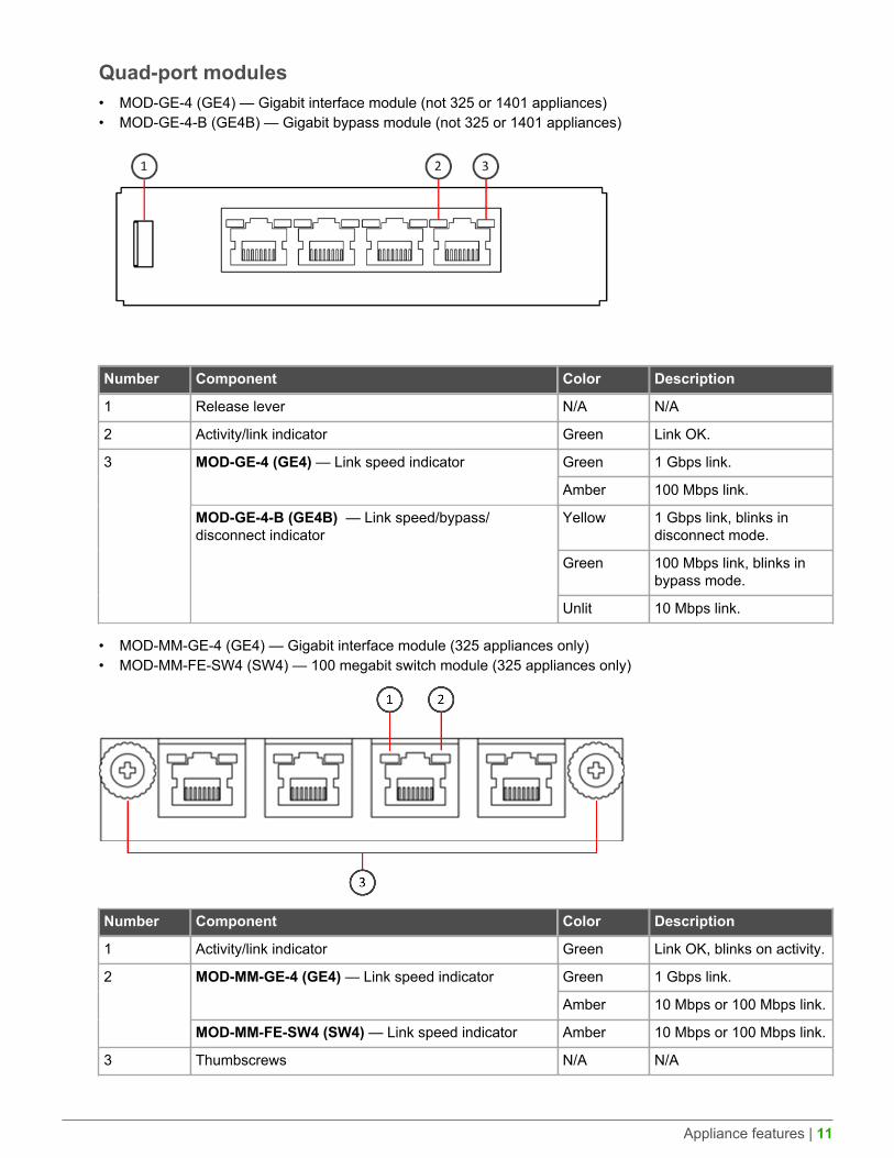
Quad-port modules• MOD-GE-4 (GE4) — Gigabit interface module (not 325 or 1401 appliances)• MOD-GE-4-B (GE4B) — Gigabit bypass module (not 325 or 1401 appliances)
Number Component Color Description
1 Release lever N/A N/A
2 Activity/link indicator Green Link OK.
Green 1 Gbps link.MOD-GE-4 (GE4) — Link speed indicator
Amber 100 Mbps link.
Yellow 1 Gbps link, blinks indisconnect mode.
Green 100 Mbps link, blinks inbypass mode.
3
MOD-GE-4-B (GE4B) — Link speed/bypass/disconnect indicator
Unlit 10 Mbps link.
• MOD-MM-GE-4 (GE4) — Gigabit interface module (325 appliances only)• MOD-MM-FE-SW4 (SW4) — 100 megabit switch module (325 appliances only)
Number Component Color Description
1 Activity/link indicator Green Link OK, blinks on activity.
Green 1 Gbps link.MOD-MM-GE-4 (GE4) — Link speed indicator
Amber 10 Mbps or 100 Mbps link.
2
MOD-MM-FE-SW4 (SW4) — Link speed indicator Amber 10 Mbps or 100 Mbps link.
3 Thumbscrews N/A N/A

Appliance features | 12
Six-port gigabit interface module• MOD-GE-6 (GE6)
Number Component Color Description
1 Release lever N/A N/A
2 Activity/link indicator Green Link OK.
3 Link speed indicator Green 1 Gbps, 100 Mbps, or 10 Mbps link.
Eight-port gigabit interface module• MOD-GE-8 (GE8) (not 325 appliances)
Number Component Color Description
1 Port numbers 0–7 N/A N/A
2, 5 Activity/link indicator Green Link OK, blinks on activity.
Yellow 1 Gbps link.
Green 100 Mbps link.
3, 6 Link speed indicator
Unlit 10 Mbps link.
4 Release lever N/A N/A

Appliance features | 13
Fiber interface modulesStonesoft NGFW appliances support these fiber interface modules.
Dual-port bypass modules• MOD-GE-SX-2-B (GESX2B) — Gigabit bypass module (1035, 1065, and 1402 appliances only)• MOD-10G-SR-2-B (10GSR2B) — 10 gigabit bypass module (1035, 1065, and 1402 appliances only)• MOD-10G-LR-2-B (10GLR2B) — 10 gigabit bypass module (1035, 1065, and 1402 appliances only)
Number Component Color Description
1 Release lever N/A N/A
2 Activity/link indicator Green Link OK.
Blue 10 Gbps link.MOD-10G-SR-2-B, MOD-10G-LR-2-B —Link speed/bypass/disconnect indicator
Green Blinks in bypass mode.
Green 1 Gbps link, blinks in bypass mode.
3
MOD-GE-SX-2-B — Link speed/bypass/disconnect indicator
Yellow Blinks in disconnect mode.
Quad-port gigabit bypass module• MOD-GE-SX-4-B (GESX4B) (1035, 1065, and 1402 appliances only)
Number Component Color Description
1 Release lever N/A N/A
2 Activity/link indicator Green Link OK.
3 Link speed/bypass/disconnect indicator Green 1 Gbps link, blinks in bypass mode.

Appliance features | 14
Number Component Color Description
Yellow Blinks in disconnect mode.
SFP interface modulesStonesoft NGFW appliances support these SFP interface modules.
Single-port gigabit interface module (SFP)• MOD-MM-GE-SFP (325 appliances only)
Number Component Color Description
1 Activity/link/link speed indicator Green 1 Gbps link (other speeds not supported),blinks on activity.
2 Thumbscrews N/A N/A
Dual-port interface modules• MOD-10G-SFP-2 (10GSFP2) — 10 gigabit interface module (SFP+) (1065, 1401, and 1402 appliances only)
Number Component Color Description
1 Release lever N/A N/A
2 Activity/link indicator Green Link OK.
3 Link speed indicator Blue 10 Gbps link.
• MOD-40G-2 — 40 gigabit interface module (QSFP+) (1401 and 1402 appliances only)

Appliance features | 15
Number Component Color Description
1 Release lever N/A N/A
2 Activity/link/link speed indicator Green 40 Gbps link (other speeds not supported),blinks on activity.
Quad-port interface modules• MOD-GE-SFP-4 (GE4SFP) — Gigabit interface module (SFP) (not 321 or 325 appliances)• MOD-10G-SFP-4 (10GSFP4) — 10 gigabit interface module (SFP+) (1065, 1401, and 1402 appliances only)• MOD-EM2-10G-SFP-4 — 10 gigabit interface module (SFP+) (1401 and 1402 appliances only)
Number Component Color Description
1 Release lever N/A N/A
2 Activity/link indicator Green Link OK.
MOD-GE-SFP-4 (GE4SFP) — Link speed indicator Yellow 1 Gbps link.
MOD-10G-SFP-4 (10GSFP4) — Link speed indicator Blue 10 Gbps link.
3
MOD-EM2-10G-SFP-4 — Link speed indicator Blue 10 Gbps link.
Placeholder modulesA placeholder module (MOD-PH) does not contain a network interface card or any ports.
If you do not have interface modules that contain a network interface card for all slots in the modular appliance,you must insert placeholder modules in the remaining slots.
Precautions | 16
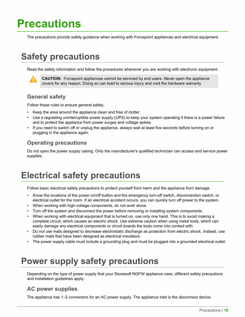
PrecautionsThe precautions provide safety guidance when working with Forcepoint appliances and electrical equipment.
Safety precautionsRead the safety information and follow the procedures whenever you are working with electronic equipment.
CAUTION: Forcepoint appliances cannot be serviced by end users. Never open the appliancecovers for any reason. Doing so can lead to serious injury and void the hardware warranty.
General safetyFollow these rules to ensure general safety.
• Keep the area around the appliance clean and free of clutter.• Use a regulating uninterruptible power supply (UPS) to keep your system operating if there is a power failure
and to protect the appliance from power surges and voltage spikes.• If you need to switch off or unplug the appliance, always wait at least five seconds before turning on or
plugging in the appliance again.
Operating precautionsDo not open the power supply casing. Only the manufacturer's qualified technician can access and service powersupplies.
Electrical safety precautionsFollow basic electrical safety precautions to protect yourself from harm and the appliance from damage.
• Know the locations of the power on/off button and the emergency turn-off switch, disconnection switch, orelectrical outlet for the room. If an electrical accident occurs, you can quickly turn off power to the system.
• When working with high-voltage components, do not work alone.• Turn off the system and disconnect the power before removing or installing system components.• When working with electrical equipment that is turned on, use only one hand. This is to avoid making a
complete circuit, which causes an electric shock. Use extreme caution when using metal tools, which caneasily damage any electrical components or circuit boards the tools come into contact with.
• Do not use mats designed to decrease electrostatic discharge as protection from electric shock. Instead, userubber mats that have been designed as electrical insulators.
• The power supply cable must include a grounding plug and must be plugged into a grounded electrical outlet.
Power supply safety precautionsDepending on the type of power supply that your Stonesoft NGFW appliance uses, different safety precautionsand installation guidelines apply.
AC power suppliesThe appliance has 1–2 connectors for an AC power supply. The appliance inlet is the disconnect device.

Precautions | 17
DC power supplies• The appliance must be used in a restricted access location and users must be well trained to operate it.• The outlet for the appliance must be installed near the appliance and be easily accessible.• We recommend using, at maximum, a 10A fuse and a power switch between the appliance and the main
power source.• The appliance must be protected against electric shock and must have, at minimum, a 15 AWG wire provided
for the DC power supply.• The mains supply plug on the power supply cable is the disconnect device on the appliance. To disconnect
the appliance, you must first disconnect the mains, then disconnect the ground.• The female and the male connectors of the DC power supply must be easy to disconnect.
Note: 1035 and 1065 appliances that have a dual input feed DC power supply might cause, atmaximum, a 500 mA current from one input feed to another. This occurs only when the voltagesat the appliance's input feeds are the same and power is no longer supplied by one of the powersources.
Note: Standby power is supplied to the 321 and 325 appliances even when the appliance isturned off.

Install the appliance | 18
Install the appliancePrepare and install the appliance in your network.
• You have installed a Stonesoft Management Center (SMC) on a separate server.• You have configured the Security Engine element (Firewall, IPS, or Layer 2 Firewall) in the Management
Client, and saved the initial configuration on a USB drive.
Note: For additional information on SMC installation and initial configuration, see the StonesoftNext Generation Firewall Installation Guide.
• You have inspected the appliance, the delivery box, and all components included in the shipment.
Note: Do not use damaged appliances or components.
Note: 321 and 325 appliances do not require rack-mounting and can be placed on a surface suchas a desk or rack shelf.
Install an interface moduleIf needed, install any interface modules.
• Read the safety precautions.• To avoid damaging the modules or the appliance, do not install or remove any interface modules if the
appliance is turned on.• Make sure any interface modules you install are the correct type for your appliance.
You must install an interface module or a placeholder module in each slot before making the applianceoperational. For 325, 1035, and 1065 appliances, you can cover the interface slot with the plate that shipped withthe appliance.
Note: We recommend fastening a grounding strap to your wrist so that it contacts your bare skinand attaching the other end of the strap to the appliance.
1. Locate the slot to install the module in.2. (325, 1035, and 1065 appliances) Unfasten the thumbscrew that attaches the plate to the interface module
slot and remove the plate.Store the plate and the thumbscrew for later use in case you want to use the appliance without an interfacemodule.
3. Push the module into the slot.
The module is seated correctly when the front panel of the module is even with the front panel of theappliance.
Tip: If the module has a sticker, make sure that the sticker faces down for 325 appliances.For other 1U appliances, the sticker faces up.
Important: Do not insert the module in the wrong orientation. Inserting the modulesincorrectly might damage the appliance and the modules and voids the warranty.
4. (325 appliances only) Turn the thumbscrews on the module to secure the module in place.

Install the appliance | 19
Rack-mount the applianceThe rack-mounting procedure varies depending on the type of rack unit. If needed, see the documentation foryour rack unit.
Important: Read the safety precautions before you rack-mount the appliance. Do not install theappliance upside down.
You can install the appliance into a two-post, a four-post, or a Telco-type rack unit. You can place 321 and 325appliances on a horizontal surface such as a desk or rack shelf.
Preparing for rack-mountingThe rack-mounting kit includes the mounting screws and the rail assemblies or rack-mounting brackets to installthe system into the rack.
Determine the placement of each component in the rack.
• Install the heaviest components on the bottom of the rack first. Install components from the bottom to the top.• The appliance must be connected to a grounded power outlet.• Use a UPS to protect the appliance from power surges and voltage spikes, and to keep your system operating
if there is a power failure.• To maintain proper cooling, always keep the front door of the rack and all panels and components on the
appliances closed when not servicing.
Install a 321 or 325 appliance in a four-post rackUse the rack-mounting brackets to secure the appliance in the rack.
The brackets and screws are not included by default. You can order them separately.
1. Locate the brackets for the four-post rack installation.The bracket delivery includes one power supply mounting bracket and two side brackets of different sizes.The larger side bracket is for 321 appliances and the smaller for 325 appliances. The delivery also includes acover plate for the power supply mounting bracket.
Tip: You can use the power supply mounting bracket for storing a power supply.
1. Power supply mounting bracket

Install the appliance | 20
2. Side brackets
2. Unscrew the pair of screws from both sides of the appliance.
CAUTION: Do not reuse these screws for attaching the brackets. The screws are not longenough to properly attach the brackets.
3. Attach the power supply mounting bracket to the left side of the appliance with two screws through the holesin the side of the bracket.The narrow part of the bracket attaches toward the back of the appliance.
Note: Use two screws to attach the rack-mounting bracket to the appliance. Using only asingle screw does not provide sufficient support and can damage the appliance.
1. Power supply mounting bracket2. Cover plate3. Front panel4. Side bracket
4. (Optional) Attach the cover plate to the front of the power supply mounting bracket with four screws throughthe holes in the cover plate.
Note: If you want to use the power supply mounting bracket for storing a power supply, donot cover the front of the bracket with the cover plate.
5. Attach the side bracket to the right side of the appliance with two screws through the holes in the side of thebracket.The narrow part of the bracket attaches toward the back of the appliance.

Install the appliance | 21
Note: Use two screws to attach the rack-mounting bracket to the appliance. Using only asingle screw does not provide sufficient support and can damage the appliance.
6. Attach each bracket to the rack with three screws through the holes in the front of the bracket: one screwthrough the top hole, the second through the middle hole, and the third through the bottom hole.
CAUTION: Use at least two screws to attach each rack-mounting bracket to the rack. Usingfewer screws might not provide sufficient support and can damage the appliance.
Install a 1035 or 1065 appliance in a two-post rackUse the rack-mounting brackets to secure the appliance in the rack.
When installing the appliance into a two-post Telco-type rack, you must move the rack-mounting brackets into thecorrect position on the side of the appliance before attaching the rack-mounting brackets to the rack.
1. Detach the rack-mounting brackets from the appliance by removing the screws on each side of theappliance. There are six screws on each side.
Tip: You can optionally remove the lifting handle from the bracket by removing the screwsthat hold the handle to the bracket.
2. Move a bracket to the back of both sides of the appliance and reattach the brackets. Use three screws foreach bracket.We recommend reattaching the six remaining screws to the front of the appliance: three on each side of theappliance.
3. Attach each bracket to the rack using two screws and cage nuts. Insert the screws through the holes in thefront of the bracket: one screw through the top hole and another through the bottom hole in the bracket.See the front panel illustration for the location of the holes.
CAUTION: Use two screws to attach each rack-mounting bracket to the rack. Using onlya single screw for each bracket does not provide sufficient support and can damage theappliance.

Install the appliance | 22
Install a 1035 or 1065 appliance in a four-post rackUse the rack-mounting brackets to secure the appliance in the rack.
Note: If you are installing the appliance into a four-post Telco-type rack, the rack-mountingbrackets on the appliance are in the correct position for installation.
1. Attach a rack-mounting bracket to the rack using two 6 millimeter screws and cage nuts. Insert the screwsthrough the holes in the front of the bracket: one screw through the top hole and another through the bottomhole in the bracket.See the front panel illustration for the location of the holes.
Note: Use two screws to attach each rack-mounting bracket to the rack. Using only a singlescrew for each bracket does not provide sufficient support and can damage the appliance.
2. Install the bracket on the other side of the appliance.
Install a 1401 or 1402 appliance in a two-post rackUse the rack-mounting brackets to secure the appliance in the rack.
1. Locate the two rack-mounting brackets for the two-post rack installation.
2. Attach a bracket to each side of the appliance with screws through the grooves in the bracket.Position the brackets to fit around the posts.

Install the appliance | 23
1. Front panel
3. Attach each bracket to the rack with three screws through the holes in the front of the bracket: one screwthrough the top hole, the second through the middle hole, and the third through the bottom hole.
CAUTION: Use all three screws to attach each rack-mounting bracket to the rack. Usingfewer screws might not provide sufficient support and can damage the appliance.
Install a 1401 or 1402 appliance with medium-lengthbrackets in a four-post rackUse the medium-length brackets (with a depth of approximately 20–30 in. or 50–76 cm) to secure the appliancein a four-post rack.
1. Locate the two pairs of brackets in the delivery package: two short brackets that attach to the appliance andtwo medium brackets that attach to the rack.
1. Short bracket (attaches to the appliance)2. Medium bracket (attaches to the rack)
2. Attach a short bracket to both sides of the appliance using two screws for each bracket.

Install the appliance | 24
1. Front panel
3. Attach the two medium brackets to the back of the rack with three screws through the holes at the back ofeach bracket: one screw through the top hole, another through the middle hole, and the third through thebottom hole.
CAUTION: Use all three screws to attach each rack-mounting bracket to the rack. Usingfewer screws might not provide sufficient support and can damage the appliance.
4. Attach two or three screws with a wider head to a suitable position on the side of the appliance. Do the samefor the other side of the appliance.
Note: These screws support the appliance when it is inserted into the rack. The number andposition of the screws depends on the depth of the rack.
5. Line up the screws that you have attached to the appliance with the groove in the brackets attached to therack.
6. Slide the appliance into the brackets in the rack.7. Attach the appliance to the rack with three screws through the holes in the front of the short brackets: one
screw through the top hole, the second through the middle hole, and the third through the bottom hole.
CAUTION: Use all three screws to attach each rack-mounting bracket to the rack. Usingfewer screws might not provide sufficient support and can damage the appliance.
Install a 1401 or 1402 appliance with long brackets in afour-post rackUse the long brackets (with a depth of approximately 27–34 in. or 70–100 cm) to secure the appliance in a four-post rack.
1. Locate the two pairs of brackets in the delivery package: two inner rails that attach to the appliance and twoouter rails that attach to the rack.

Install the appliance | 25
1. Inner rail2. Locking tab3. Outer rail
2. Detach the inner rails from the outer rails. Press down the locking tab to pull out the inner rail.3. Attach an inner rail to each side of the appliance using four screws for each rail.
• The inner rails are marked with "LH" for left and "RH" for right.• The outer rails are marked with "Front" for the front end and "Rear" for the rear end.• The outer rail that was attached to the inner rail marked "LH" must be attached to the left side of the rack,
and the outer rail that was attached to the inner rail marked "RH" must be attached to the right side of therack.
1. Front panel2. Inner rail
4. Release the safety lock on the front end of an outer rail by pulling it back.
1. Rack2. Safety lock3. Outer rail
5. Insert the outer rail into the rack.
Install the appliance | 26
If the ends of the outer rails do not fit into the holes in the rack, use the adapter brackets included in thedelivery.
6. Push the safety lock forward to secure the rail into the rack.7. Insert the other outer rail into the rack.8. Line up the rear of the inner rails with the front of the outer rails.9. Slide the inner rails into the outer rails, keeping the pressure even on both sides. You might have to press
the locking tabs when inserting.The rails lock into the rack when the appliance is pushed completely into the rack.
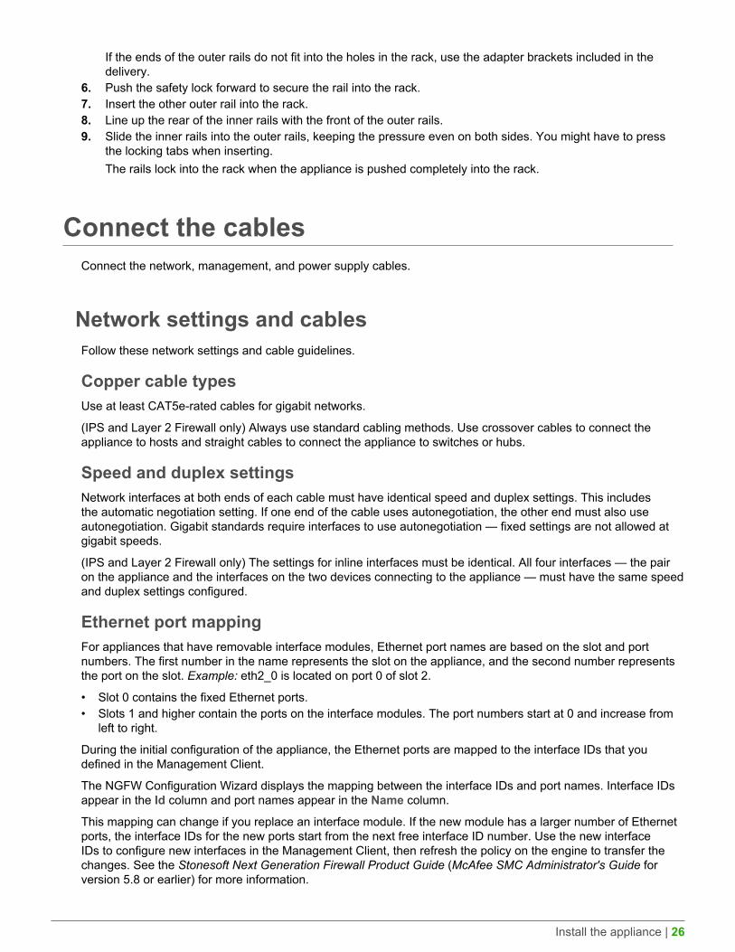
Connect the cablesConnect the network, management, and power supply cables.
Network settings and cablesFollow these network settings and cable guidelines.
Copper cable typesUse at least CAT5e-rated cables for gigabit networks.
(IPS and Layer 2 Firewall only) Always use standard cabling methods. Use crossover cables to connect theappliance to hosts and straight cables to connect the appliance to switches or hubs.
Speed and duplex settingsNetwork interfaces at both ends of each cable must have identical speed and duplex settings. This includesthe automatic negotiation setting. If one end of the cable uses autonegotiation, the other end must also useautonegotiation. Gigabit standards require interfaces to use autonegotiation — fixed settings are not allowed atgigabit speeds.
(IPS and Layer 2 Firewall only) The settings for inline interfaces must be identical. All four interfaces — the pairon the appliance and the interfaces on the two devices connecting to the appliance — must have the same speedand duplex settings configured.
Ethernet port mappingFor appliances that have removable interface modules, Ethernet port names are based on the slot and portnumbers. The first number in the name represents the slot on the appliance, and the second number representsthe port on the slot. Example: eth2_0 is located on port 0 of slot 2.
• Slot 0 contains the fixed Ethernet ports.• Slots 1 and higher contain the ports on the interface modules. The port numbers start at 0 and increase from
left to right.
During the initial configuration of the appliance, the Ethernet ports are mapped to the interface IDs that youdefined in the Management Client.
The NGFW Configuration Wizard displays the mapping between the interface IDs and port names. Interface IDsappear in the Id column and port names appear in the Name column.
This mapping can change if you replace an interface module. If the new module has a larger number of Ethernetports, the interface IDs for the new ports start from the next free interface ID number. Use the new interfaceIDs to configure new interfaces in the Management Client, then refresh the policy on the engine to transfer thechanges. See the Stonesoft Next Generation Firewall Product Guide (McAfee SMC Administrator's Guide forversion 5.8 or earlier) for more information.

Install the appliance | 27
CAUTION: Do not select the Clear action when modifying interface IDs in the NGFWConfiguration Wizard. Selecting Clear removes all mapping information between interface IDs andEthernet ports, and restores the default values.
Example: You have seven interfaces numbered 1–7, which includes a four-port module installed in slot 1.
Figure 1: Original interface ID mapping
If you replace the four-port module installed in slot 1 with a two-port module, eth1_2 with ID 4 and eth1_3 with ID5 are removed.
Figure 2: Changed interface ID mapping
Connect network and management cablesConnect the appliance to your networks. The management connection allows you to view the system console.
Note: Ethernet ports are mapped to interface IDs during the initial configuration. The ports andport numbers of the physical appliance must match the interface definitions and interface IDsconfigured for the engine in the Management Client.
1. Determine which Ethernet ports to use and connect the ports to your networks.2. Select one of these options for the management connection:
• 321, 325, 1035, and 1065 appliances — Connect the supplied null-modem cable to the console port onthe front panel of the appliance and to another computer for a terminal connection.
• 1401 and 1402 appliances — Connect a monitor to the VGA port on the front panel of the appliance anda keyboard to a USB port.
Note: The serial console is not enabled by default on 1401 and 1402 appliances andcannot be used for the initial configuration. To use the serial console after the initialconfiguration, use the command sg-bootconfig on the engine command line. For moreinformation, see Command line tools in the Stonesoft Next Generation Firewall ProductGuide (McAfee SMC Administrator's Guide for version 5.8 or earlier) for more information.
Connect network cables to SFP portsIf you installed an SFP interface module on the appliance, insert the copper or fiber-optic SFP transceiver into themodule and connect the cables.
1. Insert the SFP transceiver in the port slot until you feel the connector on the transceiver snap into place.

Install the appliance | 28
Note: Make sure that the latch on the SFP transceiver is up when you insert the SFPtransceiver in the port slot.
2. If the SFP transceiver has a rubber plug, remove the plug.3. Connect the copper or fiber-optic cable to the SFP transceiver.
Note: Each SFP port must match the wavelength specifications at the other end of the cable.The cable must not exceed the stipulated cable length for reliable communications.
Connect the antennas325 appliances have WLAN support.
1. Install the antennas to the two connectors on the back panel of the appliance.2. Tighten the knurled nuts at the base of the antennas to secure them firmly to the appliance.3. Position the antennas.
Connect the power supplies1035 and 1065 appliances might have an AC power supply or a DC power supply with a dual feed input adapter.
See Safety precautions for more information about power supplies.
Connect the AC power supplyIf your appliance has an AC power supply, connect the power cable.
Note: We recommend using a UPS to ensure continuous operation and minimize the risk ofdamage to the appliance in case of sudden loss of power.
1. Plug the cable to the AC power connector on the back of the appliance.2. Plug the cable to a grounded, high-quality power strip that offers protection from electrical noise and power
surges.
Note: Standby power is supplied to the system even when the appliance is turned off.
Connect the DC power supplySome 1035 and 1065 appliances have a DC power supply with a dual input feed adapter that must be wired forpower.
Two types of connectors are required for a DC power supply that has a dual input feed adapter:
• Male connector of the type IC 2,5/ 3-STGF-5,08 (fixed)• Female connector of the type MSTB 2,5/ 3-STF-5,08 (removable)
Figure 3: Male connector

Install the appliance | 29
Figure 4: Female connector
Note: We recommend using a UPS to ensure continuous operation and minimize the risk ofdamage to the appliance in case of sudden loss of power.
1. Assemble a female connector.1. Locate a copper cable with three wires:
• 48 V negative terminal (–)• Ground connection• 48 V positive terminal (+)
2. Strip 8 mm of insulation from each of the three wires in the cable.
CAUTION: Do not strip more than 8 mm from each wire to avoid leaving uninsulated wireexposed from the female connector.
3. If necessary, turn the screws on top of the female connector to expose the square holes for inserting thethree wires in the connector.
4. Insert the exposed part of each of the three wires into the female connector. The illustration shows thewiring.You can configure the DC input feed in three different ways, depending on your environment:
• Negative grounded (+48VDC)• Positive grounded (–48VDC)• Floating (default)
1. 48 V negative terminal (–)2. Ground connection3. 48 V positive terminal (+)
5. Tighten the screws on top of the female connector to lock the wires into place.6. Assemble the second female connector.
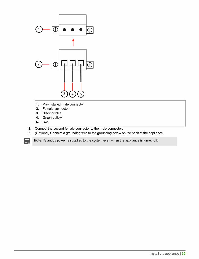
2. Connect the mating connectors.1. Insert a female connector into the pre-installed male connector as shown in the illustration.
Install the appliance | 30
1. Pre-installed male connector2. Female connector3. Black or blue4. Green-yellow5. Red
2. Connect the second female connector to the male connector.3. (Optional) Connect a grounding wire to the grounding screw on the back of the appliance.
Note: Standby power is supplied to the system even when the appliance is turned off.

Maintenance | 31
MaintenanceStonesoft NGFW appliances ship with several replaceable components.
Turn off the applianceStonesoft NGFW 1U appliance hardware components are not hot-swappable. Turn off the appliance anddisconnect power before replacing any hardware component.
Note: We recommend fastening a grounding strap to your wrist so that it contacts your bare skinand attaching the other end of the strap to the appliance.
1. Connect to the engine command line. Depending on your appliance type, use one of these options.
• Connect a keyboard to a USB port and a monitor to the VGA port, then press Enter.• Connect a computer running a terminal emulator program to the appliance console port, then press
Enter.
Note: The console port is not enabled by default on 1401 and 1402 appliances.
• Connect using SSH.
Note: SSH access is not enabled by default.
2. Enter the logon credentials.The user name is root and the password is the one you set for the appliance.
3. Enter the command halt.4. Unplug all power cords from the system or the wall outlets.
Replace the power supplyThe AC power supplies are replaceable.
CAUTION: Do not open the casing of a power supply module. Power supply modules can only berepaired by a qualified technician from the manufacturer.
Note: We recommend fastening a grounding strap to your wrist so that it contacts your bare skinand attaching the other end of the strap to the appliance.
1. Turn off the appliance and disconnect any power cables.2. Locate the release tab above the power supply module.3. Push the release tab to the right to release the power supply module from its locking position.4. Pull out the power supply module using the handle provided.5. Push the replacement power supply module into the power bay until it clicks in place.

Maintenance | 32
Replace the appliance fansReplace failed fans to ensure proper cooling of the appliance.
There are four fans on the back panel of the 1402 appliance.
We recommend that you replace all appliance fans at the same time. If one of the fans fails, the other fans mightneed replacement.
Note: We recommend fastening a grounding strap to your wrist so that it contacts your bare skinand attaching the other end of the strap to the appliance.
1. Turn off the appliance and disconnect any power cables.2. Press the release tab on the side of the appliance fan to release the fan from its locking position.3. Remove the fan from the appliance and slide the new fan into the fan housing.
Replace the CFast cardReplace the CFast card with another card that you received from Forcepoint.
Note: We recommend fastening a grounding strap to your wrist so that it contacts your bare skinand attaching the other end of the strap to the appliance.
1. Turn off the appliance and disconnect any power cables.2. Locate the CFast card on the appropriate panel for your appliance.
• 321, 325, 1035, and 1065 appliances — The card is on the back panel.• 1401 and 1402 appliances — The card is on the front panel.
3. Gently push in the CFast card to release the card from the slot.4. Position the replacement CFast card. Turn the end with the slots toward the appliance. The wider slot must
be on the left.5. Insert the new CFast card into the slot and gently push to lock the card into place.6. Reconfigure the appliance for the replacement CFast card. See the initial configuration information in the
Stonesoft Next Generation Firewall Installation Guide.
Replace an interface moduleReplace an interface module with the same type or a different type of module.
For 325, 1035, and 1065 appliances, you can replace the interface module with the plate that covered theinterface module slot at the time of delivery.
If the number of ports in the old and new module are the same, the mapping between the Interface IDs stays thesame. If the number of ports in the new module is different from the old module, or if you replace the module witha placeholder module or a cover plate, you might need to modify the interface definitions.
Note: We recommend fastening a grounding strap to your wrist so that it contacts your bare skinand attaching the other end of the strap to the appliance.
1. Turn off the appliance and disconnect any power cables.2. Release the module.
Maintenance | 33
• 325 appliances — Unscrew the thumbscrews and carefully pull the module out of the slot.• 1035, 1065, 1401, and 1402 appliances — Press the release lever, hold it down, and carefully pull the
module out of the slot using the handle or the knob on the front panel of the module.3. Insert the new module.4. Connect the cables and plug the power cables to the system and to the wall outlets.5. Turn on the appliance.
CAUTION: To ensure proper cooling, do not turn on the appliance if you have not installedan interface module or a placeholder module in each slot. For 325, 1035, and 1065appliances, you can install the cover plate over the slot instead.
6. If the number of ports in the new module differs from the old module, update the interface configuration.1. In the Management Client, modify the interface definitions as needed.2. Refresh the policy to transfer the interface changes to the engine.
Remove SFP transceiversRemove or replace an SFP transceiver.
CAUTION: Invisible laser radiation is emitted from the end of a fiber-optic cable and from the fiberport. Do not stare into the beam and avoid direct exposure to the beam.
Note: We recommend fastening a grounding strap to your wrist so that it contacts your bare skinand attaching the other end of the strap to the appliance.
1. Turn off the appliance and disconnect any power cables.2. Unplug all power cables from the system or the wall outlets.3. Disconnect the cable from the SFP transceiver.4. Pull down the latch on the transceiver and carefully pull the SFP transceiver out of the port slot.5. If needed, insert a replacement SFP transceiver in the slot.
Reattach the cover plate to the interface moduleslot
Reattach the module cover plate if there is no module in the slot.
CAUTION: Do not turn on the appliance if a slot is empty or uncovered. Using the appliancewithout an interface module or the cover plate can damage the appliance and voids the warranty.
Note: We recommend fastening a grounding strap to your wrist so that it contacts your bare skinand attaching the other end of the strap to the appliance.
1. Turn off the appliance.2. Remove the interface module from the interface module slot.3. Locate the tab at the lower left corner of the plate.4. Insert the tab into the hole in the lower left corner of the slot casing.

Maintenance | 34
5. Slide the plate inward until it covers the slot and the thumbscrew in the plate aligns with the screw hole to theright of the slot.
6. Tighten the thumbscrew until the plate is attached firmly in place.

Compliance information | 35
Compliance informationStonesoft NGFW appliances that have wireless support are in compliance with the EMC directive (2004/108/EC)and the FCC standard (FCC Part 15) for wireless devices intended for home and office use.
This information is valid for all dual band products (2.4 GHz, IEEE 802.11b/g/n, and 5 GHz, IEEE 802.11n).
The supported channels and frequencies for Stonesoft NGFW appliances are listed by country in theManagement Client. The wireless configuration is transferred to the appliance when you install the policy on theengine.
Applied technologiesThe appliance uses these technologies.
• Radio spectrum — Sub-bands 2400–2483,5 MHz, 5150–5250 MHz, 5250–5350 MHz, and 5470–5725 MHz• Safety — Dual band products• Electromagnetic Compatibility (EMC) — Dual band products
National restrictions and requirements forauthorization
These appliances can be operated within FCC DFS2 band or ETSI/EC DFS band, or other countries that regulateor plan to regulate mid-5 GHz band.
The usage of mid-5 GHz band is subject to the regulatory approval alone with the resided devices.
The requirements for any country or area might change. We recommend that you check with your localauthorities for the latest status of national requirements for 2.4 GHz and 5 GHz wireless LANs.

Find product documentation | 36
Find product documentationOn the ServicePortal, you can find information about a released product, including product documentation,technical articles, and more.
1. Go to the ServicePortal at https://support.mcafee.com and click the Knowledge Center tab.2. In the Knowledge Base pane under Content Source, click Product Documentation.3. Select a product and version, then click Search to display a list of documents.
Copyright © 1996 - 2016 Forcepoint LLC Forcepoint™ is a trademark of Forcepoint LLC.
SureView®, ThreatSeeker®, TRITON®, Sidewinder® and Stonesoft® are registered trademarks of Forcepoint LLC. Raytheon is a registered trademark of Raytheon Company.
All other trademarks and registered trademarks are property of their respective owners.


