Storage Area Network and Fibre Channel Protocol Primer 1 INTRODUCTION..............................................................................................................................1 2 SATISFYING THE MARKET’S INSATIABLE DEMAND FOR STORAGE ....................................1 3 STORAGE AREA NETWORK (SAN) OVERVIEW.........................................................................2
3.1 SCSI AND SAN DEVICE ADDRESSING, LUNS AND PRIORITIZATION EXPLAINED..................................... 3 4 DISTINGUISHING FIBRE CHANNEL FROM THE FIBRE CHANNEL PROTOCOL.....................3 5 FIBRE CHANNEL CONNECTION METHODS, A MORE DETAILED LOOK ................................3
6 HOW FIBRE CHANNEL DEVICES TALK TO ONE ANOTHER.....................................................6 6.1 PORT DEFINITIONS ............................................................................................................................. 6 6.2 NAMING OF DEVICES AND HOW THEY ARE ADDRESSED ........................................................................ 6 6.3 ESTABLISHING A CONNECTION BETWEEN PORTS.................................................................................. 7
7 TRANSPORTING DATA .................................................................................................................8 7.1 CLASSES OF SERVICE......................................................................................................................... 8 7.2 FLOW CONTROL ................................................................................................................................. 9 7.3 ERROR RECOVERY............................................................................................................................. 9 7.4 DATA TRANSPORT IN A MESHED FABRIC............................................................................................ 10
8 CONTROLLING ACCESS TO NETWORK LEGS AND DEVICES ..............................................10 8.1 ZONING............................................................................................................................................ 11
APPENDIX A – FIBRE CHANNEL CLASS OF SERVICE DESCRIPTIONS ............................................17 APPENDIX B - GLOSSARY OF TERMS...................................................................................................18 APPENDIX C – ADDITIONAL REFERENCE MATERIALS ......................................................................19
1 Introduction This white paper is an introduction to Storage Area Networks (SANs), Fibre Channel and the Fibre Channel Protocol (FCP). It provides a quick review of SCSI bus attributes and shortcomings, introduces SANs, and then explains the basics of Fibre Channel topologies. Next Fibre Channel device connection methods and data transport are described, followed by ways to control access within a network and more complex topologies using hubs and switches.
2 Satisfying the Market’s Insatiable Demand for Storage Data always seems to expand to fill the available storage space. The result has been and continues to be an ongoing quest to increase storage equipment capacity and performance. One solution has been SCSI, the Small Computer Systems Interface. This industry standard defines both physical connection details and an associated command protocol for data access, transfer and handling. It has traditionally provided high performance for relatively modest cost in small and mid-sized computer systems. However the SCSI physical layer standard has limitations making it unsuitable for large, fast or distributed systems. These limitations include:
• The use of parallel cables of limited length (25 meters maximum). • A requirement to use terminators at each end of a cable to ensure data integrity. • A tendency to suffer from signal skew at higher clock frequencies.
Network Appliance FCP White Paper, Continued FCP_white_papr_rev1_3.doc
• An inability to access data while capacity is being added. • The need for a large number of cables if terabytes of storage are required. • A rather small maximum number of storage devices.
To address these limitations the third revision of the SCSI standard, SCSI-3, separated the command protocol from the physical layer. The result is a protocol that is widely supported in the existing vendor software base and can be transported over non-SCSI media standards. One result has been the Fibre Channel Protocol, which transfers SCSI-3 commands over Fibre Channel, a high-speed serial link. These standards, FCP, Fibre Channel and SCSI-3, form the basis for building a high-speed, robust and dedicated network of storage devices commonly called a Storage Area Network or SAN.
3 Storage Area Network (SAN) Overview SCSI and standards like it attach storage devices directly to the applications server. This approach works well for single-server installations but is unsuitable when multiple servers are used, a system is physically distributed or more than one operating system is required. SANs take a different approach by putting the storage devices on a dedicated network separated from both the LAN and, if present, WAN. Figure 1 depicts a simple Storage Area Network. User workstations are located on an Ethernet LAN that connects to an applications server. The same server also connects to a Fibre Channel switch or hub that attaches to storage devices (typically disk drives). Though not shown here, one or more additional servers can be attached to the same SAN by adding a Fibre Channel Host Bus Adapter (HBA) to each and connecting it to the Fibre Channel switch or hub.
SAN LAN
Fibre Channel Switch or Hub
Disk Storage
Server
Figure 1: Sim SANs generally use Fibre ChaSpeeds for up-to-date equipmhigher speed equipment is noSAN Node gives a theoreticalSAN is dramatically lower duebe separated by up to 10 km, acceptable performance at su The following additional key a
• There is a master/slavdevice(s). The server idevices are targets. [TSCSI specification.]
Rev 1.3, May 20, 2002
Ethernet Switch
ple Storage Area Network Attached to a LAN
nnel cabling, which relies on either copper or optical fiber media. ent are typically 1 gigabit per second full duplex, although some w on the market. Although the 24-bit address assigned to each maximum of 16 million devices, the actual number of devices on a to performance and vendor equipment limitations. Devices can though once again careful design is necessary to ensure ch distances.
ttributes of SANs should be mentioned: e relationship between the applications server(s) and the storage s usually the initiator of a transaction while one or more storage he terms initiator and target originated with the first revision of the
Network Appliance FCP White Paper, Continued FCP_white_papr_rev1_3.doc
• Storage devices on a SAN are local from the perspective of the operating system in an applications server. Thus unlike remote drives these devices can be accessed at the block level. This is an important consideration for some applications such as databases.
3.1 SCSI and SAN Device Addressing, LUNs and Prioritization Explained The Fibre Channel Protocol adopts parts of the addressing and device prioritization scheme defined in the physical layer of the original SCSI standard. With SCSI four bits are used for addressing so there are a maximum of 16 device addresses or SCSI Ids. One of these is typically the server’s host adapter while the other 15 can be storage devices. The SCSI ID is also used to determine the priority of devices, with lower addresses having a higher priority. To increase the total number of storage devices on a SCSI bus, each SCSI ID can be used to access up to eight sub-devices per SCSI ID. Each such sub-device has a unique Logical Unit Number (LUN), which is supplied with a SCSI command when addressing a particular device. The Fibre Channel Protocol uses a prioritization scheme descended from the SCSI standard in which the lowest address has the highest priority. FCP also uses the concept of LUNs to limit access to particular devices.
4 Distinguishing Fibre Channel from the Fibre Channel Protocol To avoid confusion, let’s distinguish Fibre Channel from the Fibre Channel Protocol. Fibre Channel refers to a physical media or cabling, connection methods, network topologies, a bus access methodology, the framing, acknowledgement and flow control protocols, low level signaling mechanisms and the bit encoding scheme. It defines full duplex, serial transport of data, currently at speeds of 1 gigabit per second and up (although certain legacy equipment runs more slowly). The Fibre Channel Protocol, which resides at a logically higher level than the Fibre Channel (as in the layers of the OSI networking model), defines device addressing, error recovery, command sequences and the content of the payload in individual Fibre Channel frames. Data access with Fibre Channel relies on the use of serial SCSI-3 commands, making it compatible with a broad variety of file systems and database applications. Although they’ve been lumped together here, Fibre Channel actually has five independent layers, FC-0 through FC-4. The content of each is beyond the scope of this paper, though it should be noted that the Fibre Channel Protocol is one example of layer FC-4. Lower layers of these five, which are together called “Fibre Channel” in this paper, can be thought of as a robust transport service over which higher-level protocols (at the FC-4 layer) can be transmitted. Examples of these higher-level protocols include FCP, TCP/IP and HiPPI. An apt analogy is the use of Ethernet frames to move higher-level protocols such as TCP/IP, NetBIOS and SNA.
5 Fibre Channel Connection Methods, A More Detailed Look First let’s define terms used throughout subsequent discussions. These terms are: Node An end device on a SAN that sends data transmissions to and receives them from other end
devices. Examples include a storage device, a Host Bus Adapter in an applications server, etc. Although Fibre Channel switches can initiate transactions on a SAN they are not an end point that generates or consumes data so are not considered Nodes for the purpose of this paper.
Port A port is a single connection point to a Fibre Channel network. There is or can be a cable or optical fiber attached to each port of a device.
Network Appliance FCP White Paper, Continued FCP_white_papr_rev1_3.doc
Hub A hub connects Fibre Channel Nodes and shares the total available Fibre Channel bandwidth among all of them. More Nodes means less bandwidth per Node. Hubs are transparent to all Nodes. They will be discussed in more detail below.
Switch A switch connects Fibre Channel Nodes so that each connection has the full bandwidth of the Fibre Channel link. Switches are discussed at greater length below.
Now consider the three ways to connect Fibre Channel devices to one another: 1) Point-to-point; 2) Arbitrated loop; 3) Switched fabric. Each is summarized below.
5.1 Point-to-Point This topology directly connects the transmit lead of one device to the receive lead of another device and vice versa. Before a data transfer can occur the two N-ports establish a session through a login sequence, though since no other devices are attached contention for the shared media is not an issue. This topology, shown in Figure 2, provides the full bandwidth of the Fibre Channel to the attached devices, though it is unlikely that this much bandwidth can be used for a sustained period of time.
Xmit
Xmit
Rcv
RcvServer
Disk Storage
Figure 2: Point-to-Point SAN Connection Topology
5.2 Arbitrated Loop This arrangement shares the Fibre Channel bandwidth amongst all attached devices. As a result the bandwidth available to each participant is determined both by the number of devices and the level of data transfer activity between them. In short, more devices or more active devices means less bandwidth for everyone. The use by all participants of shared media also means that any device wishing to transfer data must gain control of the media. This step is accomplished with an arbitration sequence. During the arbitration sequence the priority of each device requesting media access is considered, with the lowest address having the highest priority. When the arbitration sequence ends two devices, one on each end of the transaction, have established a connection and control the media. When the transaction completes they release control of the transport media. Fibre Channel devices are attached to one another in a ring configuration when using an arbitrated loop. Figure 3 depicts an example of this. In this case the transmit port of one device connects to the receive port of the next device. The last device then connects to the first device in this same fashion. Note that Figure 3 shows logical connections only; physically there is no cable from the last device to the first.
Xmit Xmit
Rcv
Xmit Rcv
Xmit
Rcv
Rcv
Xmit Rcv
Server
Figure 3: Sample Arbitrated Loop SAN Connection Topology
Network Appliance FCP White Paper, Continued FCP_white_papr_rev1_3.doc
The simple arbitrated loop wiring arrangement diagrammed above is low in cost although a damaged cable, connection or hardware component at a single point can cause the entire loop to fail. This and the interruption caused when adding new devices is one of the reasons that a hub is frequently used for arbitrated loop configurations. As will be discussed in more detail below, the hub internally connects attached devices while also bypassing any that are faulty. Arbitrated loop is the most widely used topology due to several factors. First, it is less costly to implement than a fabric topology (described below) since a more costly switch is not required. Second, attached devices typically cannot use the full Fibre Channel bandwidth by themselves so it makes more efficient use of the available bandwidth and media investment. And finally, even in large networks there may be only a few devices that use substantial amounts of bandwidth. This and the fact that the Fibre Channel Protocol includes a mechanism to ensure that lower priority devices are never permanently starved for media access mean that arbitrated loop topologies are a practical way to divide shared bandwidth.
5.3 Switched Fabric A Fibre Channel fabric connects devices with one or more Fibre Channel fabric switches. Each device has the full Fibre Channel bandwidth available to it, so the aggregate bandwidth increases as each new device is added. An example a SAN fabric topology appears in Figure 4.
DiskStorage
Fibre Channel Fabric Switch
Server
Server
Figure 4: Sample Fabric Connection Topology for a SAN As with a point-to-point topology, fabric-capable devices must establish a session using a login sequence before transferring data. However the actual login sequence and the frames used differ in these two cases. Fabrics can and often do connect arbitrated loops to other loops and/or fabric-capable device(s). One example could be a campus on which an extended distance separates two arbitrated loops. In this scenario local data might be kept in both places to increase performance by not mixing it with long-distance traffic that suffers latency for each frame sent the full distance. Transfers between the two distributed sites could use the full media bandwidth if a fabric connection was used between the two. The fabric topology and devices capable of using it were fully developed only after point-to-point and arbitrated loop arrangements. As a result legacy devices may not contain firmware or a device driver capable of supporting the services necessary to implement a switched fabric topology. Devices that are so capable are called “fabric-aware” or “fabric-capable” in this paper.
Network Appliance FCP White Paper, Continued FCP_white_papr_rev1_3.doc
6 How Fibre Channel Devices Talk to One Another
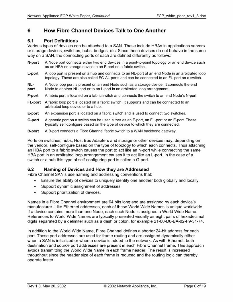
6.1 Port Definitions Various types of devices can be attached to a SAN. These include HBAs in applications servers or storage devices, switches, hubs, bridges, etc. Since these devices do not behave in the same way on a SAN, the connecting ports of each are defined differently as follows: N-port A Node port connects either two end devices in a point-to-point topology or an end device such
as an HBA or storage device to an F-port on a fabric switch.
L-port A loop port is present on a hub and connects to an NL-port of an end Node in an arbitrated loop topology. These are also called FC-AL ports and can be connected to an FL-port on a switch.
NL-port
A Node loop port is present on an end Node such as a storage device. It connects the end Node to another NL-port or to an L-port in an arbitrated loop arrangement.
F-port A fabric port is located on a fabric switch and connects the switch to an end Node’s N-port.
FL-port A fabric loop port is located on a fabric switch. It supports and can be connected to an arbitrated loop device or to a hub.
E-port An expansion port is located on a fabric switch and is used to connect two switches.
G-port A generic port on a switch can be used either as an F-port, an FL-port or an E-port. These typically self-configure based on the type of device to which they are connected.
B-port A B-port connects a Fibre Channel fabric switch to a WAN backbone gateway. Ports on switches, hubs, Host Bus Adapters and storage or other devices may, depending on the vendor, self-configure based on the type of topology to which each connects. Thus attaching an HBA port to a fabric switch causes the port to act like an N-port while connecting the same HBA port in an arbitrated loop arrangement causes it to act like an L-port. In the case of a switch or a hub this type of self-configuring port is called a G-port.
6.2 Naming of Devices and How they are Addressed Fibre Channel SAN’s use naming and addressing conventions that:
• Ensure the ability of devices to uniquely identify one another both globally and locally. • Support dynamic assignment of addresses. • Support prioritization of devices.
Names in a Fibre Channel environment are 64 bits long and are assigned by each device’s manufacturer. Like Ethernet addresses, each of these World Wide Names is unique worldwide. If a device contains more than one Node, each such Node is assigned a World Wide Name. References to World Wide Names are typically presented visually as eight pairs of hexadecimal digits separated by a delimiter such as a dash or colon, for example 21-00-D0-BA-02-F9-31-74. In addition to the World Wide Name, Fibre Channel defines a shorter 24-bit address for each port. These port addresses are used for frame routing and are assigned dynamically either when a SAN is initialized or when a device is added to the network. As with Ethernet, both destination and source port addresses are present in each Fibre Channel frame. This approach avoids transmitting the World Wide Name in each frame header. The result is increased throughput since the header size of each frame is reduced and the routing logic can thereby operate faster.
Network Appliance FCP White Paper, Continued FCP_white_papr_rev1_3.doc
Visually a port address is generally shown as three pairs of hexadecimal digits separated by a delimiter such as a dash or colon, for example xx-yy-zz. One of these pairs, i.e. eight bits, represents the Domain Number, another the Area Number and the third a Node port number. The specifics of how these port address field assignments are made internal to a switch is usually proprietary to a particular vendor. The upper 16 bits of a 24-bit port address form a loop identifier, while the lowest order byte is called an Arbitrated Loop Port Address (ALPA). The loop identifier is non-zero in public loops, which are by definition attached to a larger SAN through a fabric switch. Devices on a public loop can be accessed from anywhere on a SAN to which they connect. In addition, an identical loop identifier value is used for all port addresses on the same public loop while the ALPA uniquely identifies each such port. The loop identifier and the ALPA for each device on a public loop are verified and can be reassigned during a fabric login to prevent conflicts with other loops in the same network. A loop identifier of zero indicates a private loop. Devices on a private loop are accessible only to other devices sharing the same loop As with a public loop, the ALPA for each port on a private loop is unique and is assigned (with Loop Initialization Primitives or LIPs) during loop initialization or when a new device is attached to the loop. Figure 5 depicts a SAN containing both public and private loops. Loop A is private since it does not connect to a switch and Loop B is public because it does. Note that Server B contains two HBAs, permitting it to connect to both loops.
Loop B Loop A
Private Loop
FibreChannel
Hub
Fibre Channel Hub
Fibre Channel Fabric Switch
Disk Storage
Server A
Disk StoragePublicLoop
Disk Storage
Server B
Disk Storage
Figure 5: Sample SAN Topology Showing Public and Private Loops The use of an 8-bit ALPA does not mean that 256 unique devices can be attached to an arbitrated loop. The requirements of clock recovery circuitry mean that equal numbers of 0’s and 1’s must be transmitted on the serial line. The bit-encoding scheme used by Fibre Channel in fact supports a total of 127 unique ALPAs. Performance constraints may, however, dictate that a far smaller number of devices attach to a loop.
6.3 Establishing a Connection between Ports Before any data transfers can occur all ports in a SAN must be assigned names and addresses as discussed above and all initiators (typically the HBAs in applications servers) must determine what targets (usually disk drives or other slave devices) exist. This latter process relies on port
Network Appliance FCP White Paper, Continued FCP_white_papr_rev1_3.doc
login capability built into the Fibre Channel Protocol. The login sequence is different for each type of topology. Point-to-point topologies use an N-port login sequence. During this sequence a port address is assigned to the device at each end of the link and communications parameters are exchanged. The resulting connection is maintained since there are no other devices competing for it. Private loop arrangements, after assigning a unique ALPA to each port during an initialization sequence, also use an N-port login sequence. Generally this takes the form of each initiator sending a port login frame to every one of the 126 possible ALPAs. Devices that respond with their communications parameters become known to each initiator as a loop participant. Other exchanges, typically initiated by an HBA device driver, take place between loop devices to associate the low level ALPA of each target device with its higher-level logical attributes such as SCSI address and LUN values (recall that the FCP uses SCSI-3 commands). Fabric topologies connect each device to a switch port and use a fabric login sequence. This topic is covered in more detail in section 9.2.1.
7 Transporting Data Fibre Channel communication is hierarchically organized based on frames, sequences and exchanges. Frames, which represent the lowest level of this hierarchy, are used to move data across the Fibre Channel and have a maximum size of 2148 bytes. Frame structure, depicted in Figure 6, consists of a start-of-frame (SOF) delimiter, a header (normally 24 bytes), a data field, a 32-bit cyclic redundancy code (CRC) and an end-of-frame delimiter. The header contains source and destination addresses as well as control information such as whether or not a frame is the first in a sequence of related frames. The data field may contain from 0 to 2112 bytes.
( )
End of Frame
Delimiter
Payload (Data Field;
2112 bytes max)(
Start of Frame
Delimiter (4 bytes)
Figure Frames can be grouped together be grouped into exchanges. A seqspecific initiator (an N-port) to a paof an individual file being read fromservice, be acknowledged. Frametransfer occurs. In this latter case An exchange, the highest level of non-concurrent but related sequenunidirectional or, if data is movingunique ports, but an individual por
7.1 Classes of Service Fibre Channel is used for a numberequirements for speed, available diverse requirements, the FCP de1 through class 6 and class F. Eac
Rev 1.3, May 20, 2002
Header 24 bytes)
6: Fibre Channel Frame
into higher-level objects cauence is a set of related drticular recipient (an N- or or written to disk. Seque
s are always transmitted inthe next sequence may st
the communication syntaxces representing a compl
back and forth, bi-directiont may manage more than
r of different applications,bandwidth, priority and dafines seven classes of serh is distinguished from the
lled sequences, which in turn can ata frames transferred from a NL-port). A sequence might consist nces may, depending on the level of order except when a streaming
art before the last one ends.
hierarchy, contains one or more ete transaction. It can be al. A single exchange involves two
one exchange concurrently.
each of which may have different ta integrity. To accommodate these vice. These are referred to as class others based on its attributes, for
liance, Inc. Page 8 of 19
Network Appliance FCP White Paper, Continued FCP_white_papr_rev1_3.doc
example: 1) Whether a dedicated connection is established giving a pair of ports sole use of the transport media for the duration of the connection; 2) Whether a recipient sends an acknowledgement of each transfer; 3) Whether a multicast service is defined; 4) Whether a class is used only for communication between fabric switches. Class 3 is the only one used by Fibre Channel Storage Area Networks that implement the Fibre Channel Protocol. Class 3 service is connectionless and multiplexes a number of transactions on the Fibre Channel media. It does not provide an acknowledgement of each transfer, making it similar to a UDP datagram service. The absence of an acknowledgement results in lower overhead, however it also means that a higher-level protocol must ensure in-order receipt of frames and must detect and request retransmission of lost or corrupted frames. Delivery of frames in class 3 is on a best efforts basis, making it inappropriate for certain fabric environments since a switch may discard class 3 frames when heavily loaded. Note, however, that class 3 is perfectly appropriate in many installations and in fact is the most widely implemented class of service in Fibre Channel networks. For example arbitrated loop arrangements, which by definition use a dedicated connection between two ports, frequently use class 3 service. For additional information about other classes of service, see Appendix A.
7.2 Flow Control Two types of flow control are defined by Fibre Channel, buffer-to-buffer and end-to-end. Both rely on credits that indicate the number of buffers available to receive and assemble arriving Fibre Channel frames. The type of flow control used is determined by the topology and class of service. For further details see one of the references at the end of this paper.
7.3 Error Recovery Error recovery in a Fibre Channel SAN is independent of flow control. As explained above, flow control relies on buffer-to-buffer and end-to-end credits and is part of the basic data transfer mechanism that moves frames. Error recovery, by contrast, relies first of all on detection and then on retransmission of one or more sequences in which frames have been lost or corrupted. Detection of an error can occur in any one of several ways. Examples include failure of a CRC test at the target, out of order sequence numbers at the destination or failure to receive an acknowledgement at the initiator if class 2 service is in use. In all these cases detection occurs at the Fibre Channel level, although this level is not capable of initiating a retransmission. As a result a higher-level protocol must intervene to determine what has been lost and must be retransmitted. With the FCP, SCSI-3 is that higher-level protocol. The speed of error recovery may vary based on the class of service used for a connection. For example an initiator using a connection with a class 2 level of service will become aware of lost frames more rapidly because one or more acknowledgements will fail to arrive. In this case it can signal a higher-level protocol that retransmission is necessary. A class 3 implementation (which does not use acknowledgements) would, however, have to wait either to receive a notification from the target that an out-of-order frame arrived (thus a frame must have been lost) or wait for a SCSI timeout to occur. Note also that retransmission in Fibre Channel implementations involves sending an entire sequence, even if only one piece of it was lost or corrupted. This approach is taken since it is
Network Appliance FCP White Paper, Continued FCP_white_papr_rev1_3.doc
more efficient to resend an entire sequence at gigabit speeds than it is to provide logic that can determine which frame(s) were lost or damaged.
7.4 Data Transport in a Meshed Fabric To ensure high reliability, a SAN may be constructed with more than one path to each destination. An example of such a topology is shown in Figure 7.
Disk Storage
Server
Fibre ChannelFabric Switch
Disk Storage
TapeBackup Server
Disk Storage
Fibre ChannelFabric Switch
Server
Fibre Channel Fabric Switch
Figure 7: Meshed Fabric SAN The use of such a topology means that frames may take more than one path to a destination. The arrival of the same frame at a single destination more than once must be prevented in order to avoid triggering retransmission (if the destination port sees out of order frames) and/or out-of-order assembly of data at the receiving end. To avoid this problem switches in such installations typically implement a protocol called Fabric Shortest Path First (FSPF). FSPF, which is described in the FCP standard FC-SW2, automatically determines the most efficient (lowest cost) path to a destination and keeps redundant routes on standby in case the primary data path fails. The result is a single active route to each destination and the assurance that frames will be delivered in order.
8 Controlling Access to Network Legs and Devices In many SAN installations it is important to create two or more virtual networks, parts of which may or may not overlap. The reasons for doing so are varied and may include:
• Security - Access via the public Internet to part of a SAN may be necessary while a simultaneous but competing requirement mandates protection of other parts of the same SAN from hacker attacks.
• Traffic and Bandwidth Management - Segregating a network can be a way to partition bandwidth.
• Segregate Certain Resources While Sharing Others - Departments of a larger organization may wish to separate certain computing resources such as servers while sharing others such as wiring and switches.
• Incompatible Operating Systems or Software - Operating systems typically assume they have exclusive use of storage resources. Limiting access can ease integration of otherwise incompatible systems that share storage resources.
Network Appliance FCP White Paper, Continued FCP_white_papr_rev1_3.doc
There are two basic methods by which access can be controlled to parts of a SAN: 1) Access zoning or, more simply, zoning; 2) LUN masking.
8.1 Zoning Zoning involves creating two or more virtual private sets of devices such as application servers, ports, storage resources, backup devices, etc. that share a Fibre Channel infrastructure. Access between sets or zones can be controlled based on the destination network address, the World Wide Name or the switch port to which the destination is attached. Traffic from one zone can be prevented from entering other zones and each device or port can belong to zero or more zones. As a simple example of zoning, consider the SAN depicted in Figure 8. Zone A contains applications server 1, which is attached to the Internet, and storage sub-system 1. Zone B contains Unix-based server 2 and storage sub-systems 2 and 4. Zone C contains Unix-based server 3 and storage sub-systems 3 and 4. Such a configuration provides public access to Zone A while separating it from the other servers and storage sub-systems for security reasons. Zone B ensures exclusive access of its Unix-based server to dedicated storage (sub-system 2), while still preserving access to shared storage on sub-system 4. Zone C is similar to Zone B since it keeps dedicated storage private but shared storage accessible. There are two types of zoning, hard and soft. Both must read the source and destination addresses in each frame and decide whether to forward or discard the frame based on whether the source and destination are members of the same zone. Each is described below.
Hub
Hub
Fabric Switch
Server 2
Disk Storage 3 Server 1
(Windows®)
Public Internet
Disk Storage 1
Server 3 (Unix)
Hub
Storage Subsystem 4
Zone CZone A
Zone B
Figure 8: Zones in a Switched Fab
8.1.1 Soft Zoning Soft zoning utilizes software or firmware to determine whether its destination or discarded. A fabric switch that implements sotakes the following steps each time it receives a frame:
1. Read the source and destination port addresses in the
a frame should be forwarded to ft zoning by network address
frame.
nce, Inc. Page 11 of 19
Network Appliance FCP White Paper, Continued FCP_white_papr_rev1_3.doc
2. Determine if the source and destination devices are in the same zone and either forward or discard the frame accordingly.
Soft zoning by port is similar, except that the switch:
1. Reads the source and destination port addresses in the frame. 2. Determines the ports to which the switch source and destination devices are attached. 3. Determines if these two devices are in the same zone and either forward or discard the
frame accordingly. Soft zoning is generally implemented by creating a table of devices, their addresses and the zones in which they reside. Since this table must be checked each time a frame is forwarded, zoning increases the latency of each transaction. The major advantage of soft zoning is that it adapts automatically whenever cables are moved to different port. Another advantage is the ability to create zones across multiple switches. One possible disadvantage of soft zoning is lower security since physical connections are still present between devices in different zones.
8.1.2 Hard Zoning Hard zoning relies on making or breaking hardware connections within a switch to control access. Once hardware zones have been created, the steps taken by a switch for each received packet are identical to those above for software zoning. The main advantage of hard zoning is its lower susceptibility to network-borne security attacks. However hard zoning is very unforgiving in cases where cables are rearranged (a device is disconnected from one switch port and reconnected to another) without first checking which zones are in use. In fact moving cables can result in servers crashing and data being corrupted on a storage sub-system. Note also that hard zoning and port zoning are not the same. This is obvious when considering that soft zoning by port is also possible. However hard zoning is always implemented by port, i.e. hard zoning by network address is not available.
8.1.3 LUN Masking As mentioned above, Fibre Channel embeds SCSI-3 commands in Fibre Channel frames. Since these commands address individual devices by SCSI address and logical unit number, it is possible to limit access to particular devices based on their SCSI address. This technique is called LUN masking. There are two ways that LUN masking is commonly implemented: 1) By software internal to an applications server; 2) By an intelligent device in a storage sub-system, for example a RAID controller. In both cases an administrator configures device accessibility by World Wide Name. LUN masking control at the server can be implemented either in the host operating system or in the device driver for a server’s HBA. The device driver approach is the most common. It permits a similar implementation across multiple platforms. Each server in this case sees all storage devices but accesses only those assigned to it. This approach is suitable only for smaller SANs since it must be manually configured on each server and becomes cumbersome and fault-prone in a disparate network with many servers and heterogeneous operating systems.
Network Appliance FCP White Paper, Continued FCP_white_papr_rev1_3.doc
LUN masking in the storage device limits the storage resources visible to each server by permitting a particular initiator to see only certain targets. No host configuration is required since a server accesses only those storage devices that it sees. This method is more suitable for large SANs. An example of LUN masking is provided in Figure 9. In this example different operating systems each have dedicated storage physically located in a single sub-system. This eliminates contention and problems associated with sharing storage across disparate operating systems.
Unix Windows®
LUN0 LUN2 LUN3 LUN1
RAIDStorage
SubsystemFabric Switch
Server 1 (Windows®)
Server 2 (Unix)
Figure 9: LUN Masking Can Ease Sharing of Storage by Heterogeneous OS’s
9 More Complex Topologies Though hubs and switches have already been mentioned and depicted in diagrams, no thorough discussion of the attributes of each has been presented. This section looks at these important devices in more detail by discussing the purpose and characteristics of each.
9.1 Hubs A hub shares a fixed amount of bandwidth among all attached devices. So more connected devices means increased contention for the same amount of bandwidth. Internally a hub, in its most basic form, is a wiring concentrator and as such is analogous to an Ethernet or Token Ring hub. It connects the transmit line of an upstream device to the receive line of a downstream device and the transmit line of the last device to the receive line of the first. Though physically devices connect in a hub and spoke manner, they actually operate in an arbitrated loop topology. Other hub attributes include:
• Transparency to other Nodes on a Fibre Channel network. Hubs are not generally addressable, though proprietary hub management techniques requiring an address do exist.
• Bypass capability for faulty Nodes. For example if the signal characteristics or jitter of the Node on port 4 do not meet certain criteria, Node 3 will be connected to Node 5 and Node 4 removed from the loop. Ports are typically bypassed for reasons such as loss of received signal, excessive jitter, off-frequency data or lack of an attached device.
• Hot insertion or removal of Nodes and automatic ALPA address reconfiguration. This results in easy addition or removal of devices without network interruption.
• Link and Bypass status LEDs that give the status of each attached device. Hubs contain L-ports for connection to the NL-ports of end Nodes in an arbitrated loop topology. Any of these ports can also be connected to an FL-port on a fabric switch.
Network Appliance FCP White Paper, Continued FCP_white_papr_rev1_3.doc
9.1.1 Maximum Number of Hub-Attached Devices Arbitrated loops can, in theory, attach to a maximum of 126 Nodes and one fabric switch. However this number of Nodes is never reached for two reasons. First, the bandwidth per Node falls too much, and second, the latency and Fibre Channel protocol overhead per loop transaction becomes excessive. For example beyond about 50 to 60 devices on an arbitrated loop the Fibre Channel protocol overhead equals or exceeds that used for data payloads. Typical hub vendor offerings contain from three to 12 ports.
9.1.2 Unmanaged and Managed Hubs Unmanaged hubs are low end interconnect devices. These usually provide:
• Basic port bypass functionality that considers only signal integrity not protocol violations. • The ability to reconfigure ALPAs when an end Node is inserted or removed. • Status LEDs.
Unmanaged hubs are a viable solution in small, low-cost installations or redundant configurations. In either case some risk is assumed since it is not possible to easily determine when or if one branch of a network fails. This is the case because such hubs cannot respond to network monitoring and management applications. Managed hubs, by contrast, do provide status reporting and thus are more intelligent. Such reporting typically includes, at a minimum, hardware integrity information for the power supply, fan, temperature and status of each individual port. More sophisticated managed hubs may monitor and report Fibre Channel protocol activity, loop integrity and loop statistics. They may also maintain an event log. These more intelligent devices may even bypass a port when detecting, for example, protocol violations. In such a case the hub has moved from the realm of mere fault reporting to fault isolation. Status information is typically made available through interfaces to one or more of the following: an SNMP management application; a Web browser; a serial port.
9.1.3 Switching Hubs Switching hubs are also called arbitrated loop switches. They are an intermediate step between hubs and switches in that they provide aggregate bandwidth sufficient for each port to operate at the full Fibre Channel speed of 1 gigabit/second. However these devices do not provide the full capability needed to service fabric-aware devices and, as a result, are lower in cost. Switching hubs are useful, for example, in environments where two or more independent arbitrated loops have sufficient bandwidth within each loop but must be connected to one another with a high-speed link. This could apply in campus locations that connect two loops by several kilometers of cabling.
9.1.4 Other Hub Features Hubs do not provide true zoning capability. However some vendor’s equipment is capable of isolating Loop Initialization Primitives (LIPs) to certain ports. This can prevent interruption of certain time-sensitive operations (e.g. streaming video or streaming tape backup). The same approach can be used to delay LIP propagation until an in-progress frame transfer is complete. As mentioned above, LIPs propagate through a loop when a device is inserted or removed from the loop and are used to reinitialize (e.g. assign ALPAs to) all remaining nodes.
Network Appliance FCP White Paper, Continued FCP_white_papr_rev1_3.doc
9.2 Fabric Services Switched fabrics of Fibre Channel Nodes provide higher performance than arbitrated loop topologies. However the fabric-capable equipment for these is more expensive due to the additional engineering required for its development. The additional services provided to fabric-aware Nodes are discussed in this section. Note that many legacy Fibre Channel Protocol devices do not support such fabric services and thus only work with private arbitrated loop or point-to-point topologies. Also, fabric-aware and fabric-incapable devices are fully compatible. In cases where a fabric-aware device is connected to a private arbitrated loop its fabric login attempt will fail and it will default to operating as a private loop Node. Should the loop later be connected to a fabric, its login attempt will succeed and it will now act as a public loop.
9.2.1 Fabric Login A fabric logon occurs when the N-port of a node is first attached to a fabric switch. During the ensuing transaction the attributes of the newly attached target device are determined and stored by the switch. These attributes include its World Wide Name, the upper level protocols supported by the target, buffer credit values that should be used when engaging in data transfers with it, etc. During this process a port address is assigned and supplied to the Node. Clearly this automated address assignment capability greatly simplifies network administration. A similar login session occurs if a fabric-capable, public loop NL-port is connected to a switch. However in this case an ALPA will already have been assigned to the NL-port during a previous loop initialization cycle. This ALPA can be rejected by the switch, which would then assign a new one and trigger another initialization cycle on that loop.
9.2.2 Simple Name Server The information received by a switch during each fabric logon is saved in a table and the result is a database of Node attributes. This database is used both to discover and to propagate the characteristics of new devices when they are attached. For example if one switch is attached to another switch, the attributes of Nodes connected to each switch must be “discovered” by the other switch. The alternative would be to poll the entire address space when a device is added to a network or two SAN legs are joined. This capability of switches is called a Simple Name Server.
9.2.3 Registered State Change Notification Since the precise devices attached to a SAN fabric at any time can and do change, it is useful to automatically notify interested end Nodes when the topology has been altered. The mechanism by which this occurs is called Registered State Change Notification (RSCN). This is a subscribed service, i.e. an N-port or fabric-capable NL-port must explicitly request such notification during a fabric logon in order to later be advised of network changes. Propagation of these network change notifications between switches uses service class F. The usefulness of RSCN becomes obvious when one considers that a server or other initiator will want to know when new storage resources (targets) appear or when previously used resources are removed. Note that State Change Notification is an earlier and slightly different form of the same service.
Network Appliance FCP White Paper, Continued FCP_white_papr_rev1_3.doc
9.2.4 Fabric Address Notification Fabric Address Notification is used to verify the validity of operating parameters and of in-progress transaction status when a loop segment is initialized during ongoing operation. This service improves throughput in arbitrated loop environments.
9.2.5 Principle Switch and Domain Address Manager Principle switch capability refers to a method for automatically selecting one switch in a complex fabric as the root switch. This in turn assures that duplicate switch addresses are not assigned. Once a root switch has been chosen the Domain Address Manager can assign a unique domain name to each switch. The end result is support for dynamic reconfiguration of a fabric when switches are added or removed.
9.3 Fabric Switches As mentioned above, fabric switches provide full Fibre Channel bandwidth to each connected device. Their higher per-port cost is justified in cases where the aggregate bandwidth used by all devices on a SAN exceeds that available in a loop topology. By definition fabric switches fully support fabric services, and most also support zoning. Firmware internal to each switch automatically assigns (and, if necessary, reassigns as the topology changes) port and switch addresses and routes frames accordingly. Note, however, that the algorithms used during port address assignment are typically vendor-specific. The result is that switches from more than vendor may not interoperate. Most vendors offer switches with ports that are intelligent enough to discover the type of Node to which each port connects and automatically self-configure that port as an F-port, an E-port or an FL-port. As can be presumed from this feature, both loop and fabric-capable Nodes can be connected in an arbitrary fashion to a fabric switch and operate properly so long as any loop devices can operate on a public loop. However legacy private loop devices that are not fabric-capable can’t generally operate like public loop devices in a fabric topology since the Fibre Channel standard provides for no such support. However some switch vendors do offer this capability as a proprietary feature. Its usefulness is clear if one considers the large installed base of fabric-incapable end Nodes such as Fibre Channel disk drives that are not likely to be replaced when newer devices are added to a SAN.
9.3.1 Switch Architecture Fabric switches generally use a cross-bar architecture. This approach creates a direct connection between each pair of ports engaged in a data transfer transaction and is typically implemented by reading only a frame’s destination address before deciding on the port through which it should be sent. The result is that part of a frame is frequently sent along its way before the entire frame has been buffered, thereby reducing latency in the switch. Memory buffers are used to hold frames as they arrive. Switch specifications typically specify the number, with each buffer usually being 2112 bytes long.
9.3.2 Blocking and Non-Blocking Switches These terms indicate whether or not an in-progress transaction between two ports that pass through a switch blocks or prevents a data transfer between another pair of ports of the same switch. A non-blocking switch permits multiple, simultaneous transactions without any one limiting the bandwidth or throughput of another. Switches are usually non-blocking.
Network Appliance FCP White Paper, Continued FCP_white_papr_rev1_3.doc
9.3.3 Cascading of Switches Like hubs, switches can be cascaded or otherwise interconnected using E-ports, though as with hubs the number of interconnected switches cannot exceed a specified maximum. This maximum is usually stated as a total number of interconnected switches and as a different and smaller number of hops between switches for each transaction. When cascading switches, each adds latency but does not reduce available bandwidth.
9.3.4 Storage Directors The terms “storage director” and “director-class switch” both refer to a switch with a larger number of ports. While standard switches may have eight or 16 ports, storage directors may have up to 32 or 64 ports.
Appendix A – Fibre Channel Class of Service Descriptions Class 1 service defines a dedicated connection between ports that have the entire bandwidth of the Fibre Channel available to them for the duration of the connection. The recipient returns an acknowledgement when each frame is received. Since only two ports have exclusive use of the media, all frames will be received in the order of transmission. Class 1 does not make good use of available bandwidth and is rarely implemented. Class 2 service doesn’t use a dedicated connection but does provide an explicit acknowledgement (ACK) of each frame transferred. The recipient also directly notifies the initiator of a failed transfer. As a result various data transfers are multiplexed onto the media in a fabric topology. Note that multiplexed transfers do not occur in an arbitrated loop using class 2 service since a pair of ports share exclusive use of the media for the duration of a transaction. Since ACKs are provided, class 2 service is well suited to mission-critical applications requiring a high level of data integrity. It is also good for traffic that occurs in short bursts. Class 4 service is connection-oriented like class 1, though it also introduces the concept of virtual circuits. Each such circuit is established in one direction between a pair of N-ports in a switched fabric and that circuit is allocated a fraction of the total available bandwidth. This bandwidth allocation is guaranteed, and a unique set of quality of service parameters is defined for each circuit. Thus a bi-directional class 4 connection consists of two virtual circuits, each of which may have a different quality of service. In addition, each N-port can establish multiple virtual circuit connections, either with one or many (up to 254) other N-ports. Class 4 provides an acknowledgement of each frame received and it ensures in-order frame delivery. It is designed for time-sensitive applications such as video-on-demand and for configurations in which each department or application would receive a fixed amount of bandwidth. Class 5 or isochronous service mandates immediate delivery of data without buffering. It has not been clearly defined yet. Class 6 service defines a connection-oriented, multicast service in which the N-port of an initiator requests that one or more destination N-ports be supplied with a stream of data. The initiator then relies on a multicast server in a SAN fabric to: 1) Receive that initiator’s output; 2) Retransmit it to all targets; 3) Receive the resulting acknowledgement from each target; 4) Supply a single acknowledgement to the initiator. The presence of the server ensures that the initiator is not swamped by the required acknowledgements from all targets. Class 6 service is designed for multicast video and audio transmission. Class F service is a connectionless service used to transfer configuration, control and management frames between fabric switch E-ports. Non-receipt of frames is reported by the
Network Appliance FCP White Paper, Continued FCP_white_papr_rev1_3.doc
destination in a transaction. Class F is similar to class 2, although the former establishes a connection between E-ports, not N-ports. The selection of a class of service is based not only on the speed and level of data integrity desired but also on factors such as bandwidth calculations. For example class 3 service may be sufficient in a fabric topology if the sum total of the bandwidth required by all initiators is substantially less than the total available bandwidth. Also, more than one class of service may be used simultaneously on the same SAN. Not all classes of service currently exist in products. In general one finds only class 2 and class 3 implemented widely for data transfers and class F for inter-switch communication.
Appendix B - Glossary of Terms Term Definition ALPA An acronym for Arbitrated Loop Port Address. Arbitrated Loop Port Address
The lowest order byte of a 24-bit port address that is used in Fibre Channel arbitrated loop topologies.
arbitrated loop switch A hub that provides full Fibre Channel bandwidth to each attached port. exchange A group of one or more non-concurrent but related Fibre Channel sequences
between a pair of ports. An exchange typically represents a single transaction such as a SCSI or IP data transfer.
domain address manager
A fabric service used in a multi-switch fabric. The domain address manager, a particular switch, assigns a unique domain name to all switches for addressing purposes.
fabric address notification
A fabric service available to each Node permitting verification of operating parameters and the status of an in-progress transaction. It typically would be used after an arbitrated loop is initialized while a transaction is occurring.
fabric-aware or fabric-capable
The ability of an end Node, HBA or other Fibre Channel device to interoperate in a Fibre Channel fabric. To do so a device must be able to perform a fabric login and/or operate as part of a public arbitrated loop.
fabric login A transaction in which an end Node establishes a logical connection with a Fibre Channel fabric switch and communicates its operating parameters.
FSPF Fabric Shortest Path First. A protocol used to determine the lowest cost path to a destination in a meshed fabric.
Fibre Channel A series of national standards that together define topology, connection and transaction methods used to move data between two devices on a high-speed, bi-directional serial bus.
Fibre Channel Protocol A standard that defines the techniques for encapsulating SCSI-3 commands within Fibre Channel frames for use on the serial Fibre Channel bus.
HiPPI High performance parallel interface. An older storage connection technology that has been mapped to Fibre Channel to improve its performance.
Host Bus Adapter An add-on hardware device that connects an I/O bus internal to a computer or other intelligent machine to a different bus such as Fibre Channel or SCSI.
initiator The SCSI bus device that commences and controls a transaction. LAN An acronym for local area network. logical unit number A numerical identifier of a particular device within a target on a SCSI bus. loop identifier The upper 16 bits of the 24-bit port address that is used in Fibre Channel
arbitrated loop topologies to uniquely identify a particular loop when more than one exists.
LUN masking A technique that can be used to limit access to particular devices based on the logical unit number portion of their SCSI address.
managed hub A Fibre Channel hub that is able to report status and, possibly, bus statistics. port address A 24-bit value that uniquely identifies a Fibre Channel connection.
Term Definition port login A login process by which an initiator establishes a connection for the purpose of
commencing a bus transaction. principle switch A fabric service used in a multi-switch fabric. The principle or root switch wins a
selection process and then assigns a unique address to all switches. private loop A Fibre Channel arbitrated topology with no switched fabric connection. public loop A Fibre Channel arbitrated topology attached to a switched fabric. registered state change notification
A fabric service in which devices register to be notified whenever changes occur to another specified node.
SCSI An acronym for Small Computer Systems Interface. sequence A series of related data frames transferred from an initiator to a target that
represents a basic unit of information. simple name server A fabric service provided by a switch that permits end Nodes to determine the
attributes of other fabric devices by querying the switch. storage director A class of Fibre Channel fabric switch with a large number of ports. switching hub A hub that provides full Fibre Channel bandwidth to each attached port. target The SCSI bus device that responds to a transaction request. WAN An acronym for Wide Area Network. World Wide Name A 64-bit identifier for a Fibre Channel device that is unique worldwide. zoning A scheme for subdividing a Fibre Channel network into two or more groups of
devices having no overlap and no ability to communicate between one another.
Appendix C – Additional Reference Materials Designing Storage Area Networks, Tom Clark, Addison-Wesley 1999 Building Storage Area Networks, Second Edition, Marc Farley, Osborne/McGraw-Hill 2001 “LUN Masking in a SAN”, Bill King, http://data.fibrechannel-europe.com/technology/index.html “IBM SAN Survival Guide”, May 2001, http://www.redbooks.ibm.com/redbooks/SG246143.html “Fabric Services”, Tom Clark, April 2000, http://www.vixel.com/whitepapers/whtppr20.pdf “Dynamic Zoning for Arbitrated Loop”, Tom Clark, September 1999, http://www.vixel.com/whitepapers/whtppr13.pdf “What is Loop Switching”, Tom Clark, January 2000, http://www.vixel.com/whitepapers/whtppr15.pdf “Storage Area Networking Association Dictionary”, http://www.snia.org Fibre Channel Standards: http://www.t11.org/index.htm Fibre Channel research papers: http://gfs.lcse.umn.edu/fc/papers/index.html