96
Veritas Storage Foundation ™ Cluster File System Administrator’s Guide AIX 5.0 N18487J
Veritas Storage Foundation™
Cluster File System Administrator’s Guide
AIX
5.0
N18487J

Veritas Storage Foundation Cluster File System Administrator’s Guide
Copyright © 2006 Symantec Corporation. All rights reserved.
SFCFS 5.0
Symantec, the Symantec logo, Storage Foundation Cluster File System are trademarks or registered trademarks of Symantec Corporation or its affiliates in the U.S. and other countries. Other names may be trademarks of their respective owners.
The product described in this document is distributed under licenses restricting its use, copying, distribution, and decompilation/reverse engineering. No part of this document may be reproduced in any form by any means without prior written authorization of Symantec Corporation and its licensors, if any.
THIS DOCUMENTATION IS PROVIDED “AS IS” AND ALL EXPRESS OR IMPLIED CONDITIONS, REPRESENTATIONS AND WARRANTIES, INCLUDING ANY IMPLIED WARRANTY OF MERCHANTABILITY, FITNESS FOR A PARTICULAR PURPOSE OR NON-INFRINGEMENT, ARE DISCLAIMED, EXCEPT TO THE EXTENT THAT SUCH DISCLAIMERS ARE HELD TO BE LEGALLY INVALID, SYMANTEC CORPORATION SHALL NOT BE LIABLE FOR INCIDENTAL OR CONSEQUENTIAL DAMAGES IN CONNECTION WITH THE FURNISHING PERFORMANCE, OR USE OF THIS DOCUMENTATION. THE INFORMATION CONTAINED IN THIS DOCUMENTATION IS SUBJECT TO CHANGE WITHOUT NOTICE.
The Licensed Software and Documentation are deemed to be “commercial computer software” and “commercial computer software documentation” as defined in FAR Sections 12.212 and DFARS Section 227.7202.
Veritas Software Corporation 20330 Stevens Creek Blvd. Cupertino, CA 95014 www.symantec.com

Third-party legal notices
Third-party software may be recommended, distributed, embedded, or bundled with this Veritas product. Such third-party software is licensed separately by its copyright holder. All third-party copyrights associated with this product are listed in the accompanying release notes.
AIX is a registered trademark of IBM Corporation.
Licensing and registration Veritas Storage Foundation Cluster File System is a licensed product. See the Veritas Storage Foundation Cluster File System Installation Guide for license installation instructions.
Technical support For technical assistance, visit http://support.veritas.com and select phone or email support. Use the Knowledge Base search feature to access resources such as TechNotes, product alerts, software downloads, hardware compatibility lists, and our customer email notification service.

Contents
Chapter 1 Technical overview Storage Foundation Cluster File System architecture ..................................... 8VxFS functionality on Cluster File Systems ...................................................... 9Storage Foundation Cluster File System benefits and applications ............12
Chapter 2 Storage Foundation Cluster File System architecture The role of component products .......................................................................15About Storage Foundation Cluster File System ..............................................17About Veritas Volume Manager cluster functionality ...................................25
Chapter 3 Storage Foundation Cluster File System administration Veritas Cluster Server overview ........................................................................33Veritas Volume Manger cluster functionality overview ................................34Storage Foundation Cluster File System overview .........................................34Storage Foundation Cluster File System administration ..............................36Snapshots on Storage Foundation Cluster File System .................................39
Chapter 4 Fencing administration I/O fencing ............................................................................................................43Troubleshooting fenced configurations ...........................................................54
Chapter 5 Veritas Volume Manager cluster functionality administration Overview of Cluster Volume Management ......................................................58
Chapter 6 Agents for Storage Foundation Cluster File System List of Storage Foundation Cluster File System Agents ................................68VCS Cluster Components ....................................................................................68Modifying the Agents and Their Resources ....................................................69Storage Foundation Cluster File System Administrative Interface .............70CFSMount Agent ..................................................................................................77CFSfsckd Agent ....................................................................................................81CVMCluster Agent ...............................................................................................82

6
CVMVolDg Agent ................................................................................................. 84
Glossary 85
Index 93
Chapter
1Technical overview
This chapter includes the following topics:
■ Storage Foundation Cluster File System architecture
■ VxFS functionality on Cluster File Systems
■ Storage Foundation Cluster File System benefits and applications,
8 Technical overview Storage Foundation Cluster File System architecture
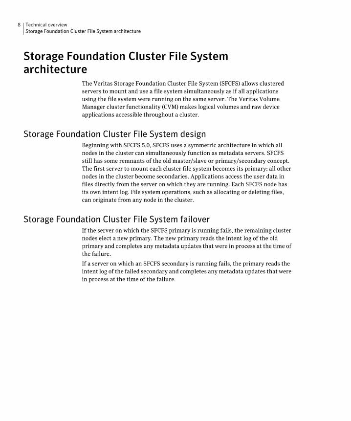
Storage Foundation Cluster File System architecture
The Veritas Storage Foundation Cluster File System (SFCFS) allows clustered servers to mount and use a file system simultaneously as if all applications using the file system were running on the same server. The Veritas Volume Manager cluster functionality (CVM) makes logical volumes and raw device applications accessible throughout a cluster.
Storage Foundation Cluster File System design Beginning with SFCFS 5.0, SFCFS uses a symmetric architecture in which all nodes in the cluster can simultaneously function as metadata servers. SFCFS still has some remnants of the old master/slave or primary/secondary concept. The first server to mount each cluster file system becomes its primary; all other nodes in the cluster become secondaries. Applications access the user data in files directly from the server on which they are running. Each SFCFS node has its own intent log. File system operations, such as allocating or deleting files, can originate from any node in the cluster.
Storage Foundation Cluster File System failover If the server on which the SFCFS primary is running fails, the remaining cluster nodes elect a new primary. The new primary reads the intent log of the old primary and completes any metadata updates that were in process at the time of the failure.
If a server on which an SFCFS secondary is running fails, the primary reads the intent log of the failed secondary and completes any metadata updates that were in process at the time of the failure.
Technical overview 9 VxFS functionality on Cluster File Systems
Group lock manager SFCFS uses the Veritas Group Lock Manager (GLM) to reproduce UNIX single-host file system semantics in clusters. This is most important in write behavior. UNIX file systems make writes appear to be atomic. This means that when an application writes a stream of data to a file, any subsequent application that reads from the same area of the file retrieves the new data, even if it has been cached by the file system and not yet written to disk. Applications can never retrieve stale data, or partial results from a previous write.
To reproduce single-host write semantics, system caches must be kept coherent and each must instantly reflect any updates to cached data, regardless of the cluster node from which they originate. GLM locks a file so that no other node in the cluster can update it simultaneously, or read it before the update is complete.
VxFS functionality on Cluster File Systems The Veritas Storage Foundation Cluster File System is based on the Veritas File System (VxFS). Most of the major features of VxFS local file systems are available on cluster file systems, including the following:
■ Extent-based space management that maps files up to a terabyte in size
■ Fast recovery from system crashes using the intent log to track recent file system metadata updates
■ Online administration that allows file systems to be extended and defragmented while they are in use
The following is a list of features and commands that operate on SFCFS. Every VxFS online manual page has a section on Storage Foundation Cluster File System Issues with information on whether the command functions on a cluster-mounted file system and indicates any difference in behavior from local mounted file systems.
See the Veritas Storage Foundation Cluster File System Release Notes.
10 Technical overview VxFS functionality on Cluster File Systems
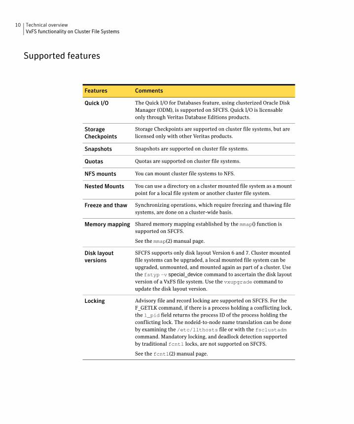
Supported features
Features Comments
Quick I/O The Quick I/O for Databases feature, using clusterized Oracle Disk Manager (ODM), is supported on SFCFS. Quick I/O is licensable only through Veritas Database Editions products.
Storage Storage Checkpoints are supported on cluster file systems, but are
Checkpoints licensed only with other Veritas products.
Snapshots Snapshots are supported on cluster file systems.
Quotas Quotas are supported on cluster file systems.
NFS mounts You can mount cluster file systems to NFS.
Nested Mounts You can use a directory on a cluster mounted file system as a mount point for a local file system or another cluster file system.
Freeze and thaw Synchronizing operations, which require freezing and thawing file systems, are done on a cluster-wide basis.
Memory mapping Shared memory mapping established by the mmap() function is supported on SFCFS.
See the mmap(2) manual page.
Disk layout SFCFS supports only disk layout Version 6 and 7. Cluster mounted
versions file systems can be upgraded, a local mounted file system can be upgraded, unmounted, and mounted again as part of a cluster. Use the fstyp –v special_device command to ascertain the disk layout version of a VxFS file system. Use the vxupgrade command to update the disk layout version.
Locking Advisory file and record locking are supported on SFCFS. For the F_GETLK command, if there is a process holding a conflicting lock, the l_pid field returns the process ID of the process holding the conflicting lock. The nodeid-to-node name translation can be done by examining the /etc/llthosts file or with the fsclustadm command. Mandatory locking, and deadlock detection supported by traditional fcntl locks, are not supported on SFCFS.
See the fcntl(2) manual page.
Technical overview 11 VxFS functionality on Cluster File Systems
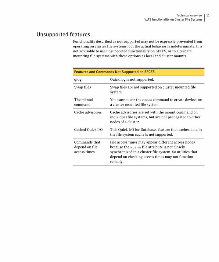
Unsupported features Functionality described as not supported may not be expressly prevented from operating on cluster file systems, but the actual behavior is indeterminate. It is not advisable to use unsupported functionality on SFCFS, or to alternate mounting file systems with these options as local and cluster mounts.
Features and Commands Not Supported on SFCFS
qlog Quick log is not supported.
Swap files Swap files are not supported on cluster mounted file system.
The mknod You cannot use the mknod command to create devices on command a cluster mounted file system.
Cache advisories Cache advisories are set with the mount command on individual file systems, but are not propagated to other nodes of a cluster.
Cached Quick I/O This Quick I/O for Databases feature that caches data in the file system cache is not supported.
Commands that File access times may appear different across nodes depend on file because the atime file attribute is not closely access times synchronized in a cluster file system. So utilities that
depend on checking access times may not function reliably.
12 Technical overview Storage Foundation Cluster File System benefits and applications
Storage Foundation Cluster File System benefits and applications
Advantages to using Storage Foundation Cluster File System SFCFS simplifies or eliminates system administration tasks that result from hardware limitations:
■ The SFCFS single file system image administrative model simplifies administration by making all file system management operations and resizing and reorganization (defragmentation) can be performed from any node.
■ Because all servers in a cluster have access to SFCFS cluster-shareable file systems, keeping data consistent across multiple servers is automatic. All cluster nodes have access to the same data, and all data is accessible by all servers using single server file system semantics.
■ Because all files can be accessed by all servers, applications can be allocated to servers to balance load or meet other operational requirements. Similarly, failover becomes more flexible because it is not constrained by data accessibility.
■ Because each SFCFS file system can be on any node in the cluster, the file system recovery portion of failover time in an n-node cluster can be reduced by a factor of n by distributing the file systems uniformly across cluster nodes.
■ Enterprise RAID subsystems can be used more effectively because all of their capacity can be mounted by all servers, and allocated by using administrative operations instead of hardware reconfigurations.
■ Larger volumes with wider striping improve application I/O load balancing. Not only is the I/O load of each server spread across storage resources, but with SFCFS shared file systems, the loads of all servers are balanced against each other.
■ Extending clusters by adding servers is easier because each new server’s storage configuration does not need to be set up—new servers simply adopt the cluster-wide volume and file system configuration.
■ The clusterized Oracle Disk Manager (ODM) feature that makes file-based databases perform as well as raw partition-based databases is available to applications running in a cluster.
Technical overview 13 Storage Foundation Cluster File System benefits and applications
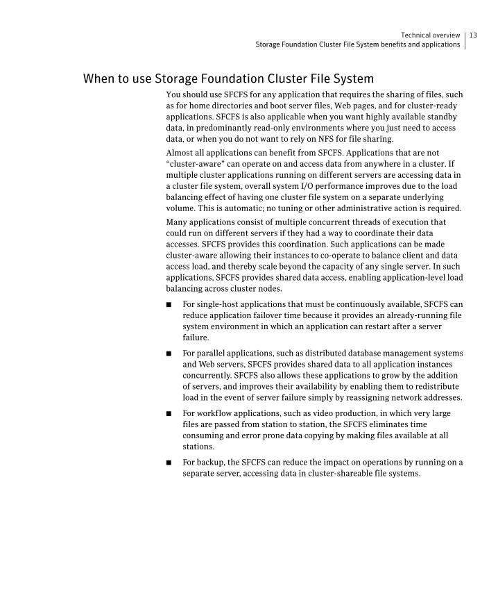
When to use Storage Foundation Cluster File System You should use SFCFS for any application that requires the sharing of files, such as for home directories and boot server files, Web pages, and for cluster-ready applications. SFCFS is also applicable when you want highly available standby data, in predominantly read-only environments where you just need to access data, or when you do not want to rely on NFS for file sharing.
Almost all applications can benefit from SFCFS. Applications that are not “cluster-aware” can operate on and access data from anywhere in a cluster. If multiple cluster applications running on different servers are accessing data in a cluster file system, overall system I/O performance improves due to the load balancing effect of having one cluster file system on a separate underlying volume. This is automatic; no tuning or other administrative action is required.
Many applications consist of multiple concurrent threads of execution that could run on different servers if they had a way to coordinate their data accesses. SFCFS provides this coordination. Such applications can be made cluster-aware allowing their instances to co-operate to balance client and data access load, and thereby scale beyond the capacity of any single server. In such applications, SFCFS provides shared data access, enabling application-level load balancing across cluster nodes.
■ For single-host applications that must be continuously available, SFCFS can reduce application failover time because it provides an already-running file system environment in which an application can restart after a server failure.
■ For parallel applications, such as distributed database management systems and Web servers, SFCFS provides shared data to all application instances concurrently. SFCFS also allows these applications to grow by the addition of servers, and improves their availability by enabling them to redistribute load in the event of server failure simply by reassigning network addresses.
■ For workflow applications, such as video production, in which very large files are passed from station to station, the SFCFS eliminates time consuming and error prone data copying by making files available at all stations.
■ For backup, the SFCFS can reduce the impact on operations by running on a separate server, accessing data in cluster-shareable file systems.
14 Technical overview Storage Foundation Cluster File System benefits and applications
The following are examples of applications and how they might work with SFCFS:
■ Using Storage Foundation Cluster File System on file servers
Two or more servers connected in a cluster configuration (that is, connected to the same clients and the same storage) serve separate file systems. If one of the servers fails, the other recognizes the failure, recovers, assumes the primaryship, and begins responding to clients using the failed server’s IP addresses.
■ Using Storage Foundation Cluster File System on web servers
Web servers are particularly suitable to shared clustering because their application is typically read-only. Moreover, with a client load balancing front end, a Web server cluster’s capacity can be expanded by adding a server and another copy of the site. A SFCFS-based cluster greatly simplifies scaling and administration for this type of application.

Chapter
2Storage Foundation Cluster File System architecture
The role of component products SFCFS includes Veritas Cluster Server (VCS) and Veritas Volume Manager (VxVM). The Veritas Cluster Server (VCS) provides the communication, configuration, and membership services required to create a cluster. VCS is the first component installed and configured to set up a cluster file system.
Veritas Cluster Server The Group Membership and Atomic Broadcast (GAB) and Low Latency Transport (LLT) are VCS-specific protocols implemented directly on an Ethernet data link. They run on redundant data links that connect the nodes in a cluster. VCS requires redundant cluster communication links to avoid single points of failure.
GAB provides membership and messaging for the cluster and its applications. GAB membership also provides orderly startup and shutdown of a cluster. The file /etc/gabtab is used to configure GAB. Configuration is done with the gabconfig command. For example, the –n option of the command specifies the number of nodes in the cluster. GAB is configured automatically when you run the VCS installation script, but you may have to reconfigure GAB when adding nodes to a cluster.
See the gabconfig(1m) manual page.

16 Storage Foundation Cluster File System architecture The role of component products
LLT provides kernel-to-kernel communications and monitors network communications. The LLT files /etc/llthosts and /etc/llttab are configured to set system IDs within a cluster, set cluster IDs for multiple clusters, and tune network parameters such as heartbeat frequency. LLT is implemented so that events such as state changes are reflected quickly, which in turn enables fast responses.
As with GAB, LLT is configured automatically when you run the VCS installation script. The file /etc/llttab contains information you provide during installation. You may also have to reconfigure LLT when adding nodes to a cluster.
See the llttab(4) manual page.
See the Veritas Cluster Server User’s Guide.
Each component in SFCFS registers with a membership port. The port membership identifies nodes that have formed a cluster for the individual components. Examples of port memberships include:
port a heartbeat membership
port b I/O fencing membership
port f Cluster File system membership
port h Veritas Cluster Server communication between GAB and High Availability Daemon (HAD)
port u Temporarily used by CVM
port v Cluster Volume Manager membership
port w Cluster Volume Manager daemons on different nodes communicate with one another using this port, but receive cluster membership information through GAB (port v).
Veritas Volume Manager cluster functionality The Veritas Volume Manager cluster functionality (CVM) makes logical volumes accessible throughout a cluster. CVM enables multiple hosts to concurrently access the logical volumes under its control. A VxVM cluster comprises nodes sharing a set of devices. The nodes are connected across a network. If one node fails, other nodes can access the devices. The VxVM cluster feature presents the same logical view of the device configurations, including changes, on all nodes. You configure CVM shared storage after VCS sets up a cluster configuration.
Storage Foundation Cluster File System architecture 17 About Storage Foundation Cluster File System
About Storage Foundation Cluster File System If the server on which the SFCFS primary is running fails, the remaining cluster nodes elect a new primary. The new primary reads the file system intent log and completes any metadata updates that were in process at the time of the failure. Application I/O from other nodes may block during this process and cause a delay. When the file system is again consistent, application processing resumes.
Because nodes using a cluster file system in secondary mode do not update file system metadata directly, failure of a secondary node does not require metadata repair. SFCFS recovery from secondary node failure is therefore faster than from primary node failure.
See “Distributing load on a cluster” on page 21.
Storage Foundation Cluster File System and the group lock manager SFCFS uses the Veritas Group Lock Manager (GLM) to reproduce UNIX single-host file system semantics in clusters. UNIX file systems make writes appear atomic. This means when an application writes a stream of data to a file, a subsequent application reading from the same area of the file retrieves the new data, even if it has been cached by the file system and not yet written to disk. Applications cannot retrieve stale data or partial results from a previous write.
To reproduce single-host write semantics, system caches must be kept coherent, and each must instantly reflect updates to cached data, regardless of the node from which they originate.
18 Storage Foundation Cluster File System architecture About Storage Foundation Cluster File System
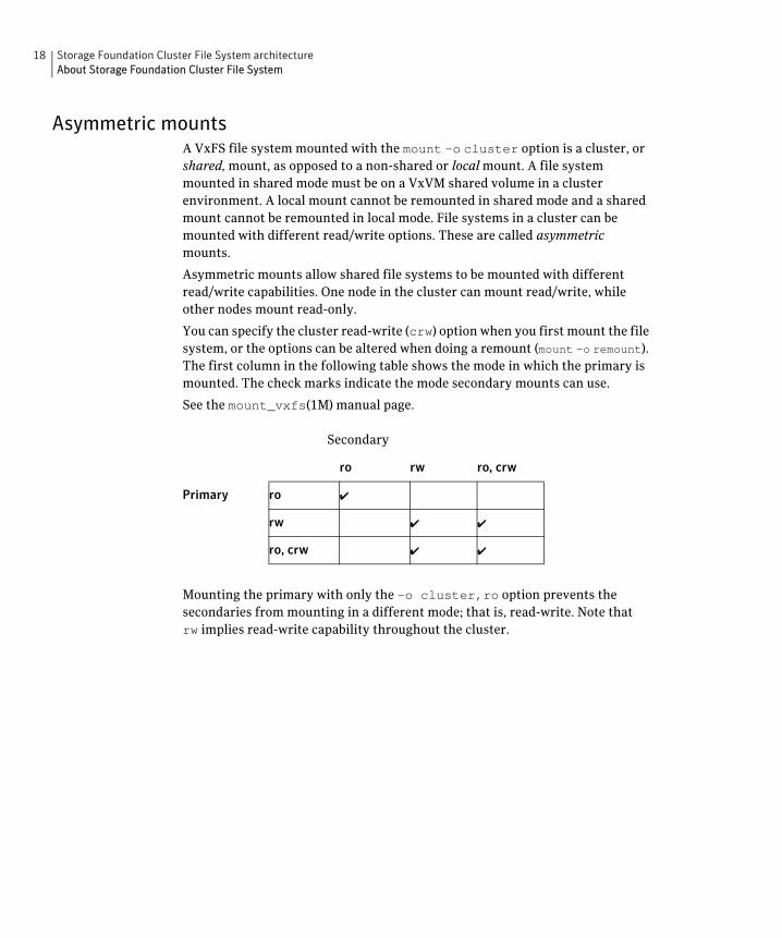
Asymmetric mounts A VxFS file system mounted with the mount –o cluster option is a cluster, or shared, mount, as opposed to a non-shared or local mount. A file system mounted in shared mode must be on a VxVM shared volume in a cluster environment. A local mount cannot be remounted in shared mode and a shared mount cannot be remounted in local mode. File systems in a cluster can be mounted with different read/write options. These are called asymmetric mounts.
Asymmetric mounts allow shared file systems to be mounted with different read/write capabilities. One node in the cluster can mount read/write, while other nodes mount read-only.
You can specify the cluster read-write (crw) option when you first mount the file system, or the options can be altered when doing a remount (mount –o remount). The first column in the following table shows the mode in which the primary is mounted. The check marks indicate the mode secondary mounts can use.
See the mount_vxfs(1M) manual page.
Secondary
ro rw ro, crw
Primary
Mounting the primary with only the –o cluster,ro option prevents the secondaries from mounting in a different mode; that is, read-write. Note that rw implies read-write capability throughout the cluster.
ro ✔
rw ✔ ✔
ro, crw ✔ ✔
Storage Foundation Cluster File System architecture 19 About Storage Foundation Cluster File System
Parallel I/O Some distributed applications read and write to the same file concurrently from one or more nodes in the cluster; for example, any distributed application where one thread appends to a file and there are one or more threads reading from various regions in the file. Several high-performance compute (HPC) applications can also benefit from this feature, where concurrent I/O is performed on the same file. Applications do not require any changes to use parallel I/O feature.
Traditionally, the entire file is locked to perform I/O to a small region. To support parallel I/O, SFCFS locks ranges in a file that correspond to an I/O request. The granularity of the locked range is a page. Two I/O requests conflict if at least one is a write request, and the I/O range of the request overlaps the I/O range of the other.
The parallel I/O feature enables I/O to a file by multiple threads concurrently, as long as the requests do not conflict. Threads issuing concurrent I/O requests could be executing on the same node, or on a different node in the cluster.
An I/O request that requires allocation is not executed concurrently with other I/O requests. Note that when a writer is extending the file and readers are lagging behind, block allocation is not necessarily done for each extending write.
If the file size can be predetermined, the file can be preallocated to avoid block allocations during I/O. This improves the concurrency of applications performing parallel I/O to the file. Parallel I/O also avoids unnecessary page cache flushes and invalidations using range locking, without compromising the cache coherency across the cluster.
For applications that update the same file from multiple nodes, the -nomtime mount option provides further concurrency. Modification and change times of the file are not synchronized across the cluster, which eliminates the overhead of increased I/O and locking. The timestamp seen for these files from a node may not have the time updates that happened in the last 60 seconds.
Storage Foundation Cluster File System namespace The mount point name must remain the same for all nodes mounting the same cluster file system. This is required for the VCS mount agents (online, offline, and monitoring) to work correctly.
20 Storage Foundation Cluster File System architecture About Storage Foundation Cluster File System
Storage Foundation Cluster File System backup strategies The same backup strategies used for standard VxFS can be used with SFCFS because the APIs and commands for accessing the namespace are the same. File System checkpoints provide an on-disk, point-in-time copy of the file system. Because performance characteristics of a checkpointed file system are better in certain I/O patterns, they are recommended over file system snapshots (described below) for obtaining a frozen image of the cluster file system.
File System snapshots are another method of a file system on-disk frozen image. The frozen image is non-persistent, in contrast to the checkpoint feature. A snapshot can be accessed as a read-only mounted file system to perform efficient online backups of the file system. Snapshots implement “copy-on-write” semantics that incrementally copy data blocks when they are overwritten on the snapped file system. Snapshots for cluster file systems extend the same copy-on-write mechanism for the I/O originating from any cluster node.
Mounting a snapshot filesystem for backups increases the load on the system because of the resources used to perform copy-on-writes and to read data blocks from the snapshot. In this situation, cluster snapshots can be used to do off-host backups. Off-host backups reduce the load of a backup application from the primary server. Overhead from remote snapshots is small when compared to overall snapshot overhead. Therefore, running a backup application by mounting a snapshot from a relatively less loaded node is beneficial to overall cluster performance.
There are several characteristics of a cluster snapshot, including:
■ A snapshot for a cluster mounted file system can be mounted on any node in a cluster. The file system can be a primary, secondary, or secondary-only. A stable image of the file system is provided for writes from any node.
■ Multiple snapshots of a cluster file system can be mounted on the same or different cluster node.
■ A snapshot is accessible only on the node mounting a snapshot. The snapshot device cannot be mounted on two nodes simultaneously.
■ The device for mounting a snapshot can be a local disk or a shared volume. A shared volume is used exclusively by a snapshot mount and is not usable from other nodes as long as the snapshot is active on that device.
■ On the node mounting a snapshot, the snapped file system cannot be unmounted while the snapshot is mounted.
■ A SFCFS snapshot ceases to exist if it is unmounted or the node mounting the snapshot fails. However, a snapshot is not affected if a node leaves or joins the cluster.

Storage Foundation Cluster File System architecture 21 About Storage Foundation Cluster File System
■ A snapshot of a read-only mounted file system cannot be taken. It is possible to mount snapshot of a cluster file system only if the snapped cluster file system is mounted with the crw option.
In addition to file-level frozen images, there are volume-level alternatives available for shared volumes using mirror split and rejoin. Features such as Fast Mirror Resync and Space Optimized snapshot are also available.
See the Veritas Volume Manager System Administrator’s Guide.
Synchronizing time on Cluster File Systems SFCFS requires that the system clocks on all nodes are synchronized using some external component such as the Network Time Protocol (NTP) daemon. If the nodes are not in sync, timestamps for creation (ctime) and modification (mtime) may not be consistent with the sequence in which operations actually happened.
Distributing load on a cluster For example, if you have eight file systems and four nodes, designating two file systems per node as the primary is beneficial. The first node that mounts a file system becomes the primary for that file system.
You can also use the fsclustadm to designate a SFCFS primary. The fsclustadm setprimary mount point can be used to change the primary. This change to the primary is not persistent across unmounts or reboots. The change is in effect as long as one or more nodes in the cluster have the file system mounted. The primary selection policy can also be defined by a VCS attribute associated with the SFCFS mount resource.
File system tuneables Tuneable parameters are updated at the time of mount using the tunefstab file or vxtunefs command. The file system tunefs parameters are set to be identical on all nodes by propagating the parameters to each cluster node. When the file system is mounted on the node, the tunefs parameters of the primary node are used. The tunefstab file on the node is used if this is the first node to mount the file system. Symantec recommends that this file be identical on each node.
22 Storage Foundation Cluster File System architecture About Storage Foundation Cluster File System
Split-brain and jeopardy handling A split-brain occurs when the cluster membership view differs among the cluster nodes, increasing the chance of data corruption. Membership change also occurs when all private-link cluster interconnects fail simultaneously, or when a node is unable to respond to heartbeat messages.With I/O fencing, the potential for data corruption is eliminated. I/O fencing requires disks that support SCSI-3 PGR.
Jeopardy state In the absence of I/O fencing, SFCFS installation requires two heartbeat links. When a node is down to a single heartbeat connection, SFCFS can no longer discriminate between loss of a system and loss of the final network connection. This state is defined as jeopardy.
SFCFS employs jeopardy to prevent data corruption following a split-brain. Note that in certain scenarios, the possibility of data corruption remains. For example:
■ All links go down simultaneously.
■ A node hangs and is unable to respond to heartbeat messages.
To eliminate the chance of data corruption in these scenarios, I/O fencing is required. With I/O fencing, the jeopardy state does not require special handling by the SFCFS stack.
Jeopardy handling For installations that do not support SCSI-3 PGR, potential split-brain conditions are safeguarded by jeopardy handling. If any cluster node fails following a jeopardy state notification, the cluster file system mounted on the failed nodes is disabled. If a node fails after the jeopardy state notification, all cluster nodes also leave the shared disk group membership.
Recovering from jeopardy The disabled file system can be restored by a force unmount and the resource can be brought online without rebooting, which also brings the shared disk group resource online. Note that if the jeopardy condition is not fixed, the nodes are susceptible to leaving the cluster again on subsequent node failure.
See the Veritas Cluster Server User’s Guide.
Storage Foundation Cluster File System architecture 23 About Storage Foundation Cluster File System
Fencing With the use of I/O enabled fencing, all remaining cases with the potential to corrupt data (for which jeopardy handling cannot protect) are addressed.
See “Fencing administration” on page 43.
Single network link and reliability Certain environments may prefer using a single private link or a pubic network for connecting nodes in a cluster, despite the loss of redundancy for dealing with network failures. The benefits of this approach include simpler hardware topology and lower costs; however, there is obviously a tradeoff with high availability.
For the above environments, SFCFS provides the option of a single private link, or using the public network as the private link if I/O fencing is present. Note that these nodes start in jeopardy state, as described in “I/O fencing” on page 43. I/O fencing is used to handle split-brain scenarios. The option for single network is given during installation.
Low priority link LLT can be configured to use a low-priority network link as a backup to normal heartbeat channels. Low-priority links are typically configured on the customer’s public or administrative network. This typically results in a completely different network infrastructure than the cluster private interconnect, and reduces the chance of a single point of failure bringing down all links. The low-priority link is not used for cluster membership traffic until it is the only remaining link. In normal operation, the low-priority link carries only heartbeat traffic for cluster membership and link state maintenance. The frequency of heartbeats drops 50 percent to reduce network overhead. When the low-priority link is the only remaining network link, LLT also switches over all cluster status traffic. Following repair of any configured private link, LLT returns cluster status traffic to the high-priority link.
24 Storage Foundation Cluster File System architecture About Storage Foundation Cluster File System
LLT links can be added or removed while clients are connected. Shutting down GAB or the high-availability daemon, HAD, is not required.
To add a link
# lltconfig -d device -t tag
To remove a link
# lltconfig -u tag
Changes take effect immediately and are lost on the next reboot. For changes to span reboots you must also update /etc/llttab.
Note: LLT clients do not recognize the difference unless only one link is available and GAB declares jeopardy.
I/O error handling policy I/O errors can occur for several reasons, including failures of Fibre Channel link, host-bus adapters, and disks. SFCFS disables the file system on the node encountering I/O errors. The file system remains available from other nodes.
After the hardware error is fixed (for example, the Fibre Channel link is reestablished), the file system can be force unmounted and the mount resource can be brought online from the disabled node to reinstate the file system.
Storage Foundation Cluster File System architecture 25 About Veritas Volume Manager cluster functionality
About Veritas Volume Manager cluster functionality CVM allows up to 32 nodes in a cluster to simultaneously access and manage a set of disks under VxVM control (VM disks). The same logical view of the disk configuration and any changes are available on each node. When the cluster functionality is enabled, all cluster nodes can share VxVM objects. Features provided by the base volume manager, such as mirroring, fast mirror resync and dirty region logging are also supported in the cluster environment.
Note: RAID-5 volumes are not supported on a shared disk group.
To implement cluster functionality, VxVM works together with the cluster monitor daemon provided by the host operating system or by VCS. The cluster monitor informs VxVM of changes in cluster membership. Each node starts up independently and has its own cluster monitor, plus its own copies of the operating system and CVM. When a node joins a cluster it gains access to shared disks. When a node leaves a cluster, it no longer has access to shared disks. A node joins a cluster when the cluster monitor is started on that node.
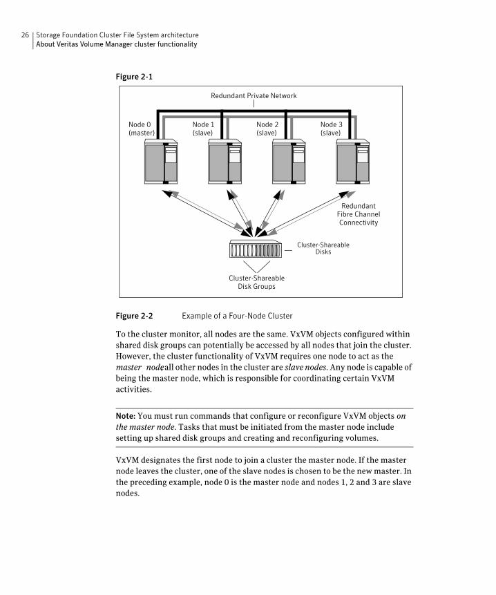
The figure “Example of a Four-Node Cluster” on page 26 illustrates a simple cluster arrangement consisting of four nodes with similar or identical hardware characteristics (CPUs, RAM and host adapters), and configured with identical software (including the operating system). The nodes are fully connected by a private network and they are also separately connected to shared external storage (either disk arrays or JBODs: just a bunch of disks) via Fibre Channel. Each node has two independent paths to these disks, which are configured in one or more cluster-shareable disk groups.
The private network allows the nodes to share information about system resources and about each other’s state. Using the private network, any node can recognize which nodes are currently active, which are joining or leaving the cluster, and which have failed. The private network requires at least two communication channels to provide redundancy against one of the channels failing. If only one channel were used, its failure would be indistinguishable from node failure—a condition known as network partitioning.
26 Storage Foundation Cluster File System architecture About Veritas Volume Manager cluster functionality
Figure 2-1
Redundant Fibre Channel Connectivity
Cluster-Shareable Disks
Redundant Private Network
Node 0 (master)
Node 1 (slave)
Node 2 (slave)
Node 3 (slave)
Cluster-Shareable Disk Groups
Figure 2-2 Example of a Four-Node Cluster
To the cluster monitor, all nodes are the same. VxVM objects configured within shared disk groups can potentially be accessed by all nodes that join the cluster. However, the cluster functionality of VxVM requires one node to act as the master node; all other nodes in the cluster are slave nodes. Any node is capable of being the master node, which is responsible for coordinating certain VxVM activities.
Note: You must run commands that configure or reconfigure VxVM objects on the master node. Tasks that must be initiated from the master node include setting up shared disk groups and creating and reconfiguring volumes.
VxVM designates the first node to join a cluster the master node. If the master node leaves the cluster, one of the slave nodes is chosen to be the new master. In the preceding example, node 0 is the master node and nodes 1, 2 and 3 are slave nodes.

Storage Foundation Cluster File System architecture 27 About Veritas Volume Manager cluster functionality
Private and shared disk groups There are two types of disk groups:
■ Private, which belong to only one node. A private disk group is only imported by one system. Disks in a private disk group may be physically accessible from one or more systems, but import is restricted to one system only. The root disk group is always a private disk group.
■ Shared, which is shared by all nodes. A shared (or cluster-shareable) disk group is imported by all cluster nodes. Disks in a shared disk group must be physically accessible from all systems that may join the cluster.
In a cluster, most disk groups are shared. Disks in a shared disk group are accessible from all nodes in a cluster, allowing applications on multiple cluster nodes to simultaneously access the same disk. A volume in a shared disk group can be simultaneously accessed by more than one node in the cluster, subject to licensing and disk group activation mode restrictions.
You can use the vxdg command to designate a disk group as cluster-shareable. When a disk group is imported as cluster-shareable for one node, each disk header is marked with the cluster ID. As each node subsequently joins the cluster, it recognizes the disk group as being cluster-shareable and imports it. You can also import or deport a shared disk group at any time; the operation takes places in a distributed fashion on all nodes.
Each physical disk is marked with a unique disk ID. When cluster functionality for VxVM starts on the master, it imports all shared disk groups (except for any that have the noautoimport attribute set). When a slave tries to join a cluster, the master sends it a list of the disk IDs that it has imported, and the slave checks to see if it can access them all. If the slave cannot access one of the listed disks, it abandons its attempt to join the cluster. If it can access all of the listed disks, it imports the same shared disk groups as the master and joins the cluster. When a node leaves the cluster, it deports all its imported shared disk groups, but they remain imported on the surviving nodes.
Reconfiguring a shared disk group is performed with the co-operation of all nodes. Configuration changes to the disk group happen simultaneously on all nodes and the changes are identical. Such changes are atomic in nature, which means that they either occur simultaneously on all nodes or not at all.
Whether all members of the cluster have simultaneous read and write access to a cluster-shareable disk group depends on its activation mode setting as discussed in “Activation modes of shared disk groups.” The data contained in a cluster-shareable disk group is available as long as at least one node is active in the cluster. The failure of a cluster node does not affect access by the remaining active nodes. Regardless of which node accesses a cluster-shareable disk group, the configuration of the disk group looks the same.
28 Storage Foundation Cluster File System architecture About Veritas Volume Manager cluster functionality
Note: Applications running on each node can access the data on the VM disks simultaneously. VxVM does not protect against simultaneous writes to shared volumes by more than one node. It is assumed that applications control consistency (by using Veritas Storage Foundation Cluster File System or a distributed lock manager, for example).
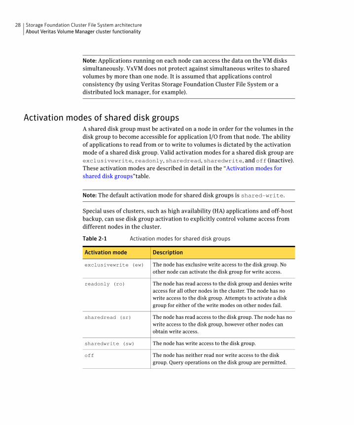
Activation modes of shared disk groups A shared disk group must be activated on a node in order for the volumes in the disk group to become accessible for application I/O from that node. The ability of applications to read from or to write to volumes is dictated by the activation mode of a shared disk group. Valid activation modes for a shared disk group are exclusivewrite, readonly, sharedread, sharedwrite, and off (inactive). These activation modes are described in detail in the “Activation modes for shared disk groups”table.
Note: The default activation mode for shared disk groups is shared-write.
Special uses of clusters, such as high availability (HA) applications and off-host backup, can use disk group activation to explicitly control volume access from different nodes in the cluster.
Table 2-1 Activation modes for shared disk groups
Activation mode Description
exclusivewrite (ew) The node has exclusive write access to the disk group. No other node can activate the disk group for write access.
readonly (ro) The node has read access to the disk group and denies write access for all other nodes in the cluster. The node has no write access to the disk group. Attempts to activate a disk group for either of the write modes on other nodes fail.
sharedread (sr) The node has read access to the disk group. The node has no write access to the disk group, however other nodes can obtain write access.
sharedwrite (sw) The node has write access to the disk group.
off The node has neither read nor write access to the disk group. Query operations on the disk group are permitted.

Storage Foundation Cluster File System architecture 29 About Veritas Volume Manager cluster functionality
The following table summarizes the allowed and conflicting activation modes for shared disk groups:
Table 2-2 Allowed and conflicting activation modes
Disk group activated in cluster as...
Attempt to activate disk group on another node as...
exclusive-write
readonly sharedread sharedwrite
exclusivewrite Fails Fails Succeeds Fails
readonly Fails Succeeds Succeeds Fails
sharedread Succeeds Succeeds Succeeds Succeeds
sharedwrite Fails Fails Succeeds Succeeds
To place activation modes under user control, create a defaults file /etc/default/vxdg containing the following lines:
enable_activation=true default_activation_mode=activation-mode
The activation-mode is one of exclusivewrite, readonly, sharedread, sharedwrite, or off.
When a shared disk group is created or imported, it is activated in the specified mode. When a node joins the cluster, all shared disk groups accessible from the node are activated in the specified mode.
Note: The activation mode of a disk group controls volume I/O from different nodes in the cluster. It is not possible to activate a disk group on a given node if it is activated in a conflicting mode on another node in the cluster. When enabling activation using the defaults file, it is recommended that this file be made identical on all nodes in the cluster. Otherwise, the results of activation are unpredictable.
If the defaults file is edited while the vxconfigd daemon is already running, the vxconfigd process must be restarted for the changes in the defaults file to take effect.
If the default activation mode is anything other than off, an activation following a cluster join, or a disk group creation or import can fail if another node in the cluster has activated the disk group in a conflicting mode.
To display the activation mode for a shared disk group, use the vxdg list diskgroup command.

30 Storage Foundation Cluster File System architecture About Veritas Volume Manager cluster functionality
You can also use the vxdg command to change the activation mode on a shared disk group.
See the Veritas Volume Manager Administrator’s Guide.
Connectivity policy of shared disk groups The nodes in a cluster must always agree on the status of a disk. In particular, if one node cannot write to a given disk, all nodes must stop accessing that disk before the results of the write operation are returned to the caller. Therefore, if a node cannot contact a disk, it should contact another node to check on the disk’s status. If the disk fails, no node can access it and the nodes can agree to detach the disk. If the disk does not fail, but rather the access paths from some of the nodes fail, the nodes cannot agree on the status of the disk. Either of the following policies for resolving this type of discrepancy may be applied:
■ Under the global connectivity policy, the detach occurs cluster-wide (globally) if any node in the cluster reports a disk failure. This is the default policy.
■ Under the local connectivity policy, in the event of disks failing, the failures are confined to the particular nodes that saw the failure. However, this policy is not highly available because it fails the node even if one of the mirrors is available. Note that an attempt is made to communicate with all nodes in the cluster to ascertain the disks’ usability. If all nodes report a problem with the disks, a cluster-wide detach occurs.
Limitations of shared disk groups The cluster functionality of VxVM does not support RAID-5 volumes, or task monitoring for cluster-shareable disk groups. These features can, however, be used in private disk groups that are attached to specific nodes of a cluster. Online relayout is supported provided that it does not involve RAID-5 volumes.
The root disk group cannot be made cluster-shareable. It must be private.
Only raw device access may be performed via the cluster functionality of VxVM. It does not support shared access to file systems in shared volumes unless the appropriate software, such as Veritas Storage Foundation Cluster File System, is installed and configured.
If a shared disk group contains unsupported objects, deport it and then re-import the disk group as private on one of the cluster nodes. Reorganize the volumes into layouts that are supported for shared disk groups, and then deport and re-import the disk group as shared.
Chapter
3Storage Foundation Cluster File System administration
The Veritas Storage Foundation Cluster File System is a shared file system that enables multiple hosts to mount and perform file operations concurrently on the same file. To operate in a cluster configuration, SFCFS requires the integrated set of Veritas products included in the Veritas Storage Foundation Cluster File System.
To configure a cluster, SFCFS requires the Veritas Cluster Server (VCS). VCS supplies two major components integral to SFCFS. The LLT package provides node-to-node communications and monitors network communications. The GAB package provides cluster state, configuration, and membership service, and monitors the heartbeat links between systems to ensure that they are active. There are several other packages supplied by VCS that provide application failover support when installing SFCFS HA.
See the Veritas Storage Foundation Cluster File System Installation Guide.
SFCFS also requires the cluster functionality (CVM) of the Veritas Volume Manager (VxVM) to create the shared volumes necessary for mounting cluster file systems.
32 Storage Foundation Cluster File System administration
Note: To install and administer cluster file systems, you should have a working knowledge of VxVM. To install and administer application failover functionality, you should have a working knowledge of VCS. For more information on these products, refer to the Veritas Volume Manager and Veritas Cluster Server documentation. The user guides for Volume Manager are available in the /opt/VRTSvmdoc directory after you install the Storage Foundation packages. The user guides for VCS are available in the /opt/VRTSvcsdc directory after you install the Storage Foundation Cluster File System HA packages.
Topics in this chapter include:
■ VCS Overview
■ CVM Overview
■ SFCFS Overview
■ SFCFS Administration
■ Snapshots on SFCFS
Storage Foundation Cluster File System administration 33 Veritas Cluster Server overview
Veritas Cluster Server overview The Veritas Cluster Server provides the communication, configuration, and membership services required to create a cluster. VCS is the first component installed and configured to set up a cluster file system.
GAB and LLT are VCS-specific protocols implemented directly on an Ethernet data link or on a Fibre Channel fabric. Both GAB and LLT run over redundant data links that connect all the servers in a cluster. VCS requires redundant cluster communication links to minimize the possibility of cluster failure due to the failure of a single communication link.
Veritas Cluster Server messaging—GAB GAB provides membership and messaging service, both for the cluster as a whole and for groups of applications running it. The GAB membership service provides orderly startup and shutdown of a cluster.
The file /etc/gabtab is used to configure GAB. Configuration is done with the gabconfig command. For example, the –n option of the command specifies the number of nodes in the cluster. GAB is configured automatically when you run the VCS installation script, but you may have to reconfigure GAB when you add a node to a cluster.
See the gabconfig(1m) manual page.
Veritas Cluster Server communication—LLT LLT provides kernel-to-kernel communications and monitors network communications. The LLT files /etc/llthosts and /etc/llttab can be configured to set system IDs within a cluster, set cluster IDs for multiple clusters, and tune network parameters such as heartbeat frequency. LLT is implemented so that events such as state changes are reflected quickly, which in turn enables fast responses.
As with GAB, LLT is configured automatically when you run the VCS installation script. The file /etc/llttab contains information derived from what you input during installation. You may also have to reconfigure LLT when you add a node to a cluster.
See the llttab(4) manual page.
34 Storage Foundation Cluster File System administration Veritas Volume Manger cluster functionality overview
Veritas Volume Manger cluster functionality overview
The cluster functionality (CVM) of the Veritas Volume Manager allows multiple hosts to concurrently access and manage a given set of logical devices under VxVM control. A VxVM cluster is a set of hosts sharing a set of devices; each host is a node in the cluster. The nodes are connected across a network. If one node fails, other nodes can still access the devices. The VxVM cluster feature presents the same logical view of the device configurations, including changes, on all nodes.
You configure CVM shared storage after VCS sets up a cluster configuration.
See “CVM Administration” on page 97.
See the Veritas Volume Manager Administrator’s Guide.
Storage Foundation Cluster File System overview A file system cluster consists of one primary, and up to 31 secondaries. The primary-secondary terminology applies to one file system, not to a specific node (or hardware platform). So it is possible to have the same cluster node be primary for one shared file system, while at the same time it is secondary for another shared file system. Such distribution of file system primaryship to balance the load on a cluster is a recommended administrative policy.
See “Distributing the load on a Cluster” on page 38.
For CVM, a single cluster node is the master for all shared disk groups and shared volumes in the cluster.
Cluster and shared mounts A VxFS file system that is mounted with the mount –o cluster option is called a cluster or shared mount, as opposed to a non-shared or local mount. A file system mounted in shared mode must be on a VxVM shared volume in a cluster environment. A local mount cannot be remounted in shared mode and a shared mount cannot be remounted in local mode. File systems in a cluster can be mounted with different read-write options. These are called asymmetric mounts.
Storage Foundation Cluster File System administration 35 Storage Foundation Cluster File System overview
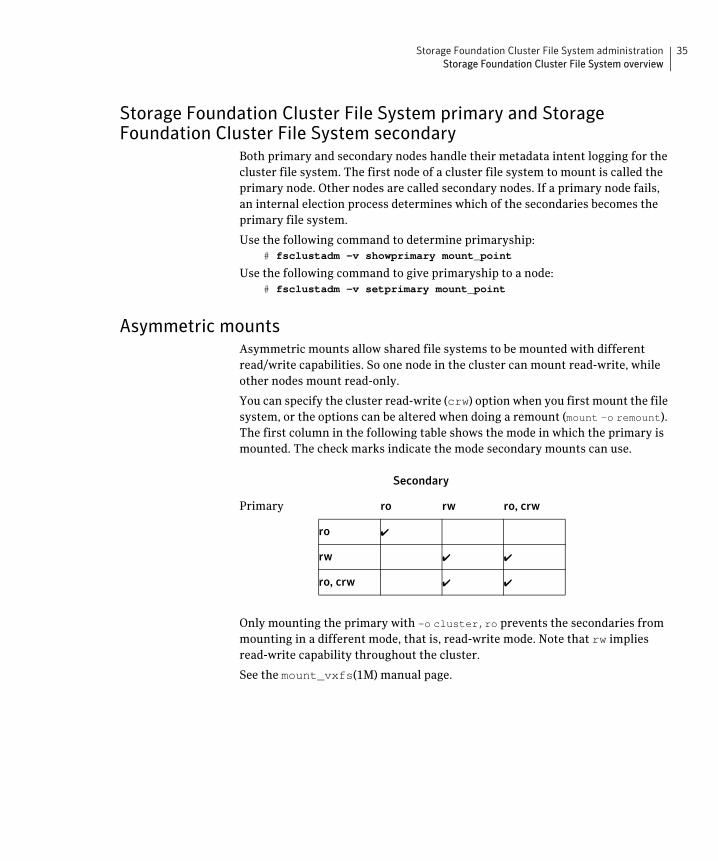
Storage Foundation Cluster File System primary and Storage Foundation Cluster File System secondary
Both primary and secondary nodes handle their metadata intent logging for the cluster file system. The first node of a cluster file system to mount is called the primary node. Other nodes are called secondary nodes. If a primary node fails, an internal election process determines which of the secondaries becomes the primary file system.
Use the following command to determine primaryship: # fsclustadm –v showprimary mount_point
Use the following command to give primaryship to a node: # fsclustadm –v setprimary mount_point
Asymmetric mounts Asymmetric mounts allow shared file systems to be mounted with different read/write capabilities. So one node in the cluster can mount read-write, while other nodes mount read-only.
You can specify the cluster read-write (crw) option when you first mount the file system, or the options can be altered when doing a remount (mount –o remount). The first column in the following table shows the mode in which the primary is mounted. The check marks indicate the mode secondary mounts can use.
Secondary
Primary ro rw ro, crw
ro ✔
rw ✔ ✔
ro, crw ✔ ✔
Only mounting the primary with –o cluster,ro prevents the secondaries from mounting in a different mode, that is, read-write mode. Note that rw implies read-write capability throughout the cluster.
See the mount_vxfs(1M) manual page.

36 Storage Foundation Cluster File System administration Storage Foundation Cluster File System administration
Storage Foundation Cluster File System and Veritas Volume Manager cluster functionality agents
Agents are VCS processes that manage predefined resource types. SFCFS and CVM require agents to interact with VCS. Agents bring resources online, take resources offline, monitor resources, and report any state changes to VCS. VCS bundled agents are part of VCS and are installed when VCS is installed. The SFCFS and CVM agents are add-on resources to VCS specifically for the Veritas File System and Veritas Volume Manager.
See “Agents for SFCFS/SFCFS HA” on page 105.
Storage Foundation Cluster File System administration
This section describes some of the major aspects of cluster file system administration and the ways in which it differs from single-host VxFS administration.
Storage Foundation Cluster File System commands The SFCFS commands are:
■ cfscluster—cluster configuration command
■ cfsmntadm—adds, deletes, modifies, and sets policy on cluster mounted file systems
■ cfsdgadm—adds or deletes shared disk groups to/from a cluster configuration
■ cfsmount/cfsumount—mounts/unmounts a cluster file system on a shared volume
Storage Foundation Cluster File System commands The mount and fsclustadm commands are also important for configuring cluster file systems.
mount The mount command with the –o cluster option lets you access shared file systems.
See the mount_vxfs(1M) manual page.
Storage Foundation Cluster File System administration 37 Storage Foundation Cluster File System administration
fsclustadm The fsclustadm command reports various attributes of a cluster file system. Using fsclustadm you can show and set the primary node in a cluster, translate node IDs to host names and vice versa, list all nodes that currently have a cluster mount of the specified file system mount point, and determine whether a mount is a local or cluster mount. The fsclustadm command operates from any node in a cluster on which the file system is mounted, and can control the location of the primary for a specified mount point.
See the fsclustadm(1M) manual page.
fsadmThe fsadm command can be invoked from the primary or secondary node.
See the fsadm(1M) manual page.
Running commands safely in a cluster environment Any UNIX command that can write to a raw device must be used carefully in a shared environment to prevent data from being corrupted. For shared VxVM volumes, SFCFS provides protection by reserving the volumes in a cluster to prevent VxFS commands, such as fsck and mkfs, from inadvertently damaging a mounted file system from another node in a cluster. However, commands such as dd execute without any reservation, and can damage a file system mounted from another node. Before running this kind of command on a file system, be sure the file system is not mounted on a cluster. You can run the mount command to see if a file system is a shared or local mount.
Time synchronization for Cluster File Systems SFCFS requires that the system clocks on all nodes are synchronized using some external component such as the Network Time Protocol (NTP) daemon. If the nodes are not in sync, timestamps for creation (ctime) and modification (mtime) may not be consistent with the sequence in which operations actually happened.

38 Storage Foundation Cluster File System administration Storage Foundation Cluster File System administration
Growing a Storage Foundation Cluster File System There is a master node for CVM as well as a primary for SFCFS. When growing a file system, you grow the volume from the CVM master, and then grow the file system from any SFCFS node. The CVM master and the SFCFS node can be two different nodes.
To determine the primary file system in a cluster, enter: # fsclustadm –v showprimary mount_point
To determine if the current node is the master CVM node, enter: # vxdctl -c mode
To actually increase the size of the file system, run the following two commands. On the master CVM node, enter:
# vxassist –g shared_disk_group growto volume_name newlength
On any SFCFS node, enter: # fsadm –V vxfs –b newsize –r device_name mount_point
The fstab file In the /etc/filesystems file, do not specify any cluster file systems to mount-at-boot because mounts initiated from filesystems occur before cluster configuration begins. For cluster mounts, use the VCS configuration file to determine which file systems to enable following a reboot.
Distributing the load on a Cluster Distributing the workload in a cluster provides performance and failover advantages.
For example, if you have eight file systems and four nodes, designating two file systems per node as the primary would be beneficial. Primaryship is determined by which node first mounts the file system. You can also use the fsclustadm to designate a SFCFS primary. The fsclustadm setprimary command can also define the order in which primaryship is assumed if the current primary fails. After setup, the policy is in effect as long as one or more nodes in the cluster have the file system mounted.
Storage Foundation Cluster File System administration 39 Snapshots on Storage Foundation Cluster File System
Using GUIs Use the Veritas Enterprise Administrator (VEA) for various VxFS functions such as making and mounting file systems, on both local and cluster file systems.
With SFCFS HA, you can use the VCS Cluster Manager GUI to configure and monitor SFCFS. The VCS GUI provides log files for debugging LLT and GAB events.
Snapshots on Storage Foundation Cluster File System
A snapshot provides a consistent point-in-time image of a VxFS file system. A snapshot can be accessed as a read-only mounted file system to perform efficient online backups of the file system. Snapshots implement copy-on-write semantics that incrementally copy data blocks when they are overwritten on the snapped file system.
See the Veritas File System Administrator’s Guide.
Snapshots for cluster file systems extend the same copy-on-write mechanism for the I/O originating from any node in the cluster.
Cluster snapshot characteristics 1 A snapshot for a cluster mounted file system can be mounted on any node in
a cluster. The file system can be a primary, secondary, or secondary-only. A stable image of the file system is provided for writes from any node.
2 Multiple snapshots of a cluster file system can be mounted on the same or a different node in a cluster.
3 A snapshot is accessible only on the node mounting a snapshot. The snapshot device cannot be mounted on two different nodes simultaneously.
4 The device for mounting a snapshot can be a local disk or a shared volume. A shared volume is used exclusively by a snapshot mount and is not usable from other nodes in a cluster as long as the snapshot is active on that device.
5 On the node mounting a snapshot, the snapped file system cannot be unmounted while the snapshot is mounted.
6 A SFCFS snapshot ceases to exist if it is unmounted or the node mounting the snapshot fails. A snapshot, however, is not affected if any other node leaves or joins the cluster.
40 Storage Foundation Cluster File System administration Snapshots on Storage Foundation Cluster File System
7 A snapshot of a read-only mounted file system cannot be taken. It is possible to mount snapshot of a cluster file system only if the snapped cluster file system is mounted with the crw option.
Performance considerations Mounting a snapshot file system for backup increases the load on the system because of the resources used to perform copy-on-writes and to read data blocks from the snapshot. In this situation, cluster snapshots can be used to do off-host backups. Off-host backups reduce the load of a backup application from the primary server. Overhead from remote snapshots is small when compared to overall snapshot overhead. Therefore, running a backup application by mounting a snapshot from a relatively less loaded node is beneficial to overall cluster performance.
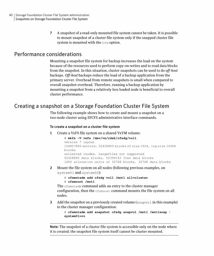
Creating a snapshot on a Storage Foundation Cluster File System The following example shows how to create and mount a snapshot on a two-node cluster using SFCFS administrative interface commands.
To create a snapshot on a cluster file system
1 Create a VxFS file system on a shared VxVM volume: # mkfs –V vxfs /dev/vx/rdsk/cfsdg/vol1version 7 layout104857600 sectors, 52428800 blocks of size 1024, log size 16384blocksunlimited inodes, largefiles not supported52428800 data blocks, 52399152 free data blocks1600 allocation units of 32768 blocks, 32768 data blocks
2 Mount the file system on all nodes (following previous examples, on system01 and system02):
# cfsmntadm add cfsdg vol1 /mnt1 all=cluster# cfsmount /mnt1
The cfsmntadm command adds an entry to the cluster manager configuration, then the cfsmount command mounts the file system on all nodes.
3 Add the snapshot on a previously created volume (snapvol in this example) to the cluster manager configuration:
# cfsmntadm add snapshot cfsdg snapvol /mnt1 /mnt1snap \system01=ro
Note: The snapshot of a cluster file system is accessible only on the node where it is created; the snapshot file system itself cannot be cluster mounted.

Storage Foundation Cluster File System administration 41 Snapshots on Storage Foundation Cluster File System
4 Mount the snapshot: # cfsmount /mnt1snap
5 A snapped file system cannot be unmounted until all of its snapshots are unmounted. Unmount the snapshot before trying to unmount the snapped cluster file system:
# cfsumount /mnt1snap

42 Storage Foundation Cluster File System administration Snapshots on Storage Foundation Cluster File System
Chapter
4Fencing administration
I/O fencing Symantec recommends configuring the cluster with I/O fencing enabled. I/O fencing requires shared devices to support SCSI-3 Persistent Reservations (PR). Enabling I/O fencing prevents data corruption caused by a split brain scenario.
Symantec Storage Foundation Cluster File System is supported without I/O fencing enabled. However, without I/O fencing enabled, split brain scenarios can result in data corruption.
I/O fencing allows write access to members of the active cluster and blocks access to non-members. The physical components of I/O fencing are data disks and coordinator disks. Each has a unique purpose and uses different physical disk devices.
See the Veritas Cluster Server Installation Guide.
See the Hardware Compatibility List (HCL) at http://support.veritas.com/docs/283161
Data disks Data disks are standard disk devices used for data storage. These can be physical disks or RAID Logical Units (LUNs). These disks must support SCSI-3 PGR. Data disks are incorporated in standard VxVM/CVM disk groups. CVM is responsible for fencing data disks on a disk-group basis. Because VxVM enables I/O fencing, several other features are also provided. Disks added to a group are automatically fenced, as are new paths to a device.

44 Fencing administration I/O fencing
Coordinator Disks Coordinator disks are special-purpose disks. They comprise three (or an odd number greater than three) standard disks, or LUNs, set aside for use by I/O fencing during cluster reconfiguration.
The coordinator disks act as a global lock device during a cluster reconfiguration. This lock mechanism determines which node is allowed to fence off data drives from other nodes. From a high level, a system must eject a peer from the coordinator disks before it can fence the peer from the data drives. This concept of “racing” for control of coordinator disks is the key to understanding how fencing helps prevent split-brain.
Coordinator disks cannot be used for any other purpose. You cannot store data on them, or include them in a disk group for user data. They can be any three disks that support SCSI-3 PGR. Symantec recommends the coordinator disks use the smallest LUNs. Because coordinator disks do not store data, cluster nodes need only register with them, not reserve them.
Before you configure coordinator disks I/O fencing requires coordinator disks to be configured in a disk group that each cluster system can access. The use of coordinator disks enables the vxfen driver to resolve potential split-brain conditions and prevent data corruption. A coordinator disk is not used for data storage, so it can be configured as the smallest LUN on a disk array to avoid wasting space.
Coordinator disks must meet the following requirements:
✔ There must be at least three coordinator disks and the total number of coordinator disks must be an odd number. This ensures a majority of disks can be achieved.
✔ Each of the coordinator disks must use a physically separate disk or LUN.
✔ Each of the coordinator disks should be on a different disk array, if possible.
✔ Coordinator disks in a disk array should use hardware-based mirroring.
✔ The coordinator disks must support SCSI-3 PR. Note that the use of the vxfentsthdw utility to test for SCSI-3 PR support requires that disks be 1MB or greater. Smaller disks can be tested manually. Contact Veritas support (http://support.veritas.com) for the procedure.
Fencing administration 45 I/O fencing
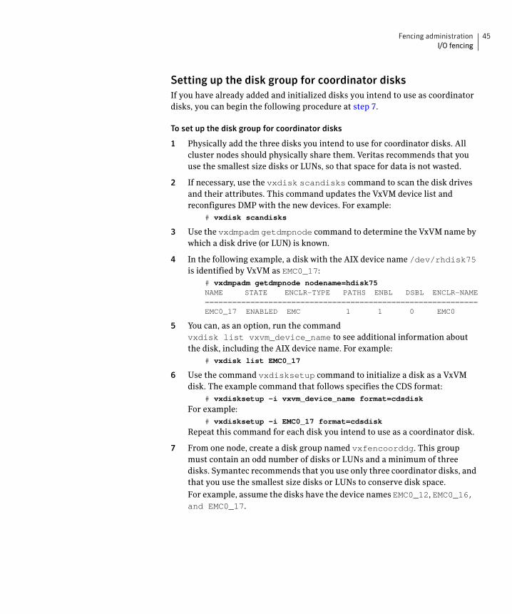
Setting up the disk group for coordinator disks If you have already added and initialized disks you intend to use as coordinator disks, you can begin the following procedure at step 7.
To set up the disk group for coordinator disks
1 Physically add the three disks you intend to use for coordinator disks. All cluster nodes should physically share them. Veritas recommends that you use the smallest size disks or LUNs, so that space for data is not wasted.
2 If necessary, use the vxdisk scandisks command to scan the disk drives and their attributes. This command updates the VxVM device list and reconfigures DMP with the new devices. For example:
# vxdisk scandisks
3 Use the vxdmpadm getdmpnode command to determine the VxVM name by which a disk drive (or LUN) is known.
4 In the following example, a disk with the AIX device name /dev/rhdisk75 is identified by VxVM as EMC0_17:
# vxdmpadm getdmpnode nodename=hdisk75NAME STATE ENCLR-TYPE PATHS ENBL DSBL ENCLR-NAME============================================================EMC0_17 ENABLED EMC 1 1 0 EMC0
5 You can, as an option, run the command vxdisk list vxvm_device_name to see additional information about the disk, including the AIX device name. For example:
# vxdisk list EMC0_17
6 Use the command vxdisksetup command to initialize a disk as a VxVM disk. The example command that follows specifies the CDS format:
# vxdisksetup -i vxvm_device_name format=cdsdisk
For example: # vxdisksetup -i EMC0_17 format=cdsdisk
Repeat this command for each disk you intend to use as a coordinator disk.
7 From one node, create a disk group named vxfencoorddg. This group must contain an odd number of disks or LUNs and a minimum of three disks. Symantec recommends that you use only three coordinator disks, and that you use the smallest size disks or LUNs to conserve disk space.
For example, assume the disks have the device names EMC0_12, EMC0_16, and EMC0_17.

46 Fencing administration I/O fencing
8 On any node, create the disk group by specifying the device name of one of the disks.
# vxdg -o coordinator=on init vxfencoorddg EMC0_12
9 Add the other two disks to the disk group. # vxdg -g vxfencoorddg adddisk EMC0_16# vxdg -g vxfencoorddg adddisk EMC0_17
See the Veritas Volume Manager Administrator’s Guide.
Requirements for testing the coordinator disk group
Running the vxfentsthdw utility Review these guidelines on testing support for SCSI-3:
■ The utility requires that the coordinator disk group be accessible from two systems. For example, if you have a four-system cluster, select any two systems for the test.
■ If you configured ssh (SSH client) for the cluster nodes, VXFENTSTHDW can be used as long as ssh commands between nodes can execute without password prompting and confirmation.
If you did not configure ssh, enable each node to have remote rsh access to the other nodes during installation and disk verification. On each node, placing a “+” character in the first line of the /.rhosts file gives remote access to the system running the install program. You can limit the remote access to specific nodes. Refer to the manual page for the /.rhosts file for more information. Remove the remote rsh access permissions after the installation and disk verification process.
■ ssh is used by default and rsh is only used if you do use the vxfentsthdw -n command.
■ To ensure both nodes are connected to the same disk during the test, use the vxfenadm -i diskpath command to verify the disk serial number.
■ The vxfentsthdw utility has additional options suitable for testing many disks. You can test disks without destroying data using the -r option. The options for testing disk groups (-g) and disks listed in a file (-f) are described in detail:

Fencing administration 47 I/O fencing
Testing the coordinator disk group After setting up, test the coordinator disk group.
To test the coordinator disk group
1 From one node, start the utility: # /opt/VRTSvcs/vxfen/bin/vxfentsthdw
Make sure system-to-system communication is functioning properly before performing this step.
See the vxfentsthdw(1M) man page.
2 After reviewing the overview and warning about overwriting data on the disks, confirm to continue the process and enter the node names.
3 Enter the name of the disk you are checking.
For example, assume you must check a shared device known by two systems as /dev/rhdisk76.
Creating the vxfendg file After setting up and testing the coordinator disk group, configure it for use.
To create the vxfendg file
1 Deport the disk group: # vxdg deport vxfencoorddg
2 Import the disk group with the -t option to avoid automatically importing it when the nodes restart:
# vxdg -t import vxfencoorddg
3 Deport the disk group. This operation prevents the coordinator disks from serving other purposes:
# vxdg deport vxfencoorddg
4 On all nodes, type: # echo "vxfencoorddg" > /etc/vxfendg
Do no use spaces between the quotes in the “vxfencoorddg” text.
This command creates the /etc/vxfendg file, which includes the name of the coordinator disk group. Based on the contents of the /etc/vxfendg file, the rc script creates the /etc/vxfentab file for use by the vxfen driver when the system starts. The rc script also invokes the vxfenconfig command, which configures the vxfen driver to start and use the coordinator disks listed in /etc/vxfentab. /etc/vxfentab is a generated file; do not modify this file.

48 Fencing administration I/O fencing
Adding or removing coordinator disks Before adding coordinator disks, verify the disks support SCSI-3 persistent reservations.
1 Log in as root on any cluster node.
2 Import the coordinator disk group. The file /etc/vxfendg includes the name of the disk group containing the coordinator disks. Type:
# vxdg -tfC import ‘cat /etc/vxfendg‘
where:
-t specifies that the disk group is imported only until the system reboots.
-f specifies that the import is to be done forcibly, which is necessary if one or more disks is inaccessible.
-C specifies any import blocks are removed.
3 To add disks to, or remove them from, the disk group, use the VxVM disk administrator utility, vxdiskadm.
4 After disks are added or removed, deport the disk group: # vxdg deport ‘cat /etc/vxfendg‘
5 Reboot each system in the cluster to make the coordinator disks accessible.
Fencing administration 49 I/O fencing
Verifying fenced configurations Administrators can use the vxfenadm command to test and troubleshoot fenced configurations. Command options include:
-d display current I/O fencing mode
-g read and display keys
-i read SCSI inquiry information from device
-m register with disks
-n make a reservation with disks
-p remove registrations made by other systems
-r read reservations
-x remove registrations
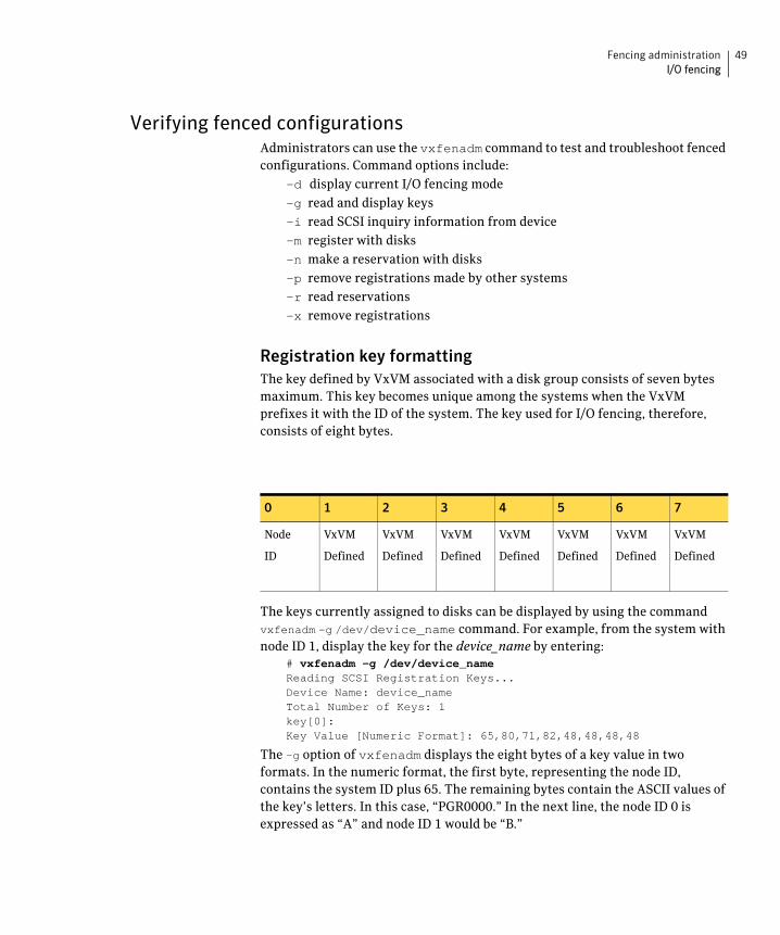
Registration key formatting The key defined by VxVM associated with a disk group consists of seven bytes maximum. This key becomes unique among the systems when the VxVM prefixes it with the ID of the system. The key used for I/O fencing, therefore, consists of eight bytes.
0 1 2 3 4 5 6 7
Node
ID
VxVM
Defined
VxVM
Defined
VxVM
Defined
VxVM
Defined
VxVM
Defined
VxVM
Defined
VxVM
Defined
The keys currently assigned to disks can be displayed by using the command vxfenadm -g /dev/device_name command. For example, from the system with node ID 1, display the key for the device_name by entering:
# vxfenadm -g /dev/device_nameReading SCSI Registration Keys...Device Name: device_nameTotal Number of Keys: 1key[0]:Key Value [Numeric Format]: 65,80,71,82,48,48,48,48
The -g option of vxfenadm displays the eight bytes of a key value in two formats. In the numeric format, the first byte, representing the node ID, contains the system ID plus 65. The remaining bytes contain the ASCII values of the key’s letters. In this case, “PGR0000.” In the next line, the node ID 0 is expressed as “A” and node ID 1 would be “B.”

50 Fencing administration I/O fencing
Disabling I/O fencing You may have to disable fencing in the following cases:
■ The cluster has been upgraded to the latest SFCFS stack and the storage does not support the SCSI-3 PGR feature.
■ During installation fencing was turned on but later disabled.
By default, the VxFEN driver operates with I/O fencing enabled. To disable this feature without removing the coordinator disks, you must create the file /etc/vxfenmode and include a string within the file to notify the VxFEN driver, then stop and restart the driver, as instructed below:
# echo "vxfen_mode=disabled" > /etc/vxfenmode# /etc/init.d/vxfen.rc stop# /etc/init.d/vxfen.rc start
Additionally, we recommend removing the /etc/vxfendg file if fencing is to be later reenabled.
How I/O fencing works during different events The following table describes how I/O fencing works to prevent data corruption during different failure scenarios. For each event, corrective actions are indicated.
Table 4-3
Event Node A: What Happens?
Node B: What Happens?
Action
All private networks fail.
Node A races for majority of coordinator disks.
If Node A wins race for coordinator disks, Node A ejects Node B from the shared disks and continues.
Node B races for majority of coordinator disks.
If Node B loses the race for the coordinator disks, Node B removes itself from the cluster.
When Node B is ejected from cluster, repair the private networks before attempting to bring Node B back.
All
private networks function again after event above.
Node A continues to work.
Node B has crashed. It cannot start the database since it is unable to write to the data disks.
Reboot Node B after private networks are restored.

Fencing administration 51 I/O fencing
Table 4-3
One private network fails.
Node A prints message about an IOFENCE on the console but continues.
Node B prints message on the console about jeopardy and continues.
Repair private network. After network is repaired, both nodes automatically use it.
Node A hangs. Node A is extremely busy for some reason or is in the kernel debugger.
When Node A is no longer hung or in the kernel debugger, any queued writes to the data disks fail because Node A is ejected. When Node A receives message from GAB about being ejected, it removes itself from the cluster.
Node B loses heartbeats with Node A, and races for a majority of coordinator disks.
Node B wins race for coordinator disks and ejects Node A from shared data disks.
Verify private networks function and reboot Node A.
Event Node A: What Happens?
Node B: What Happens?
Action

52 Fencing administration I/O fencing
Table 4-3
Nodes A and B and private networks lose power. Coordinator and data disks retain power.
Power returns to nodes and they reboot, but private networks still have no power.
Node A reboots and I/O fencing driver (vxfen) detects Node B is registered with coordinator disks. The driver does not see Node B listed as member of cluster because private networks are down. This causes the I/O fencing device driver to prevent Node A from joining the cluster. Node A console displays:
Potentially a
preexisting
split brain.
Dropping out of
the cluster.
Refer to the
user
documentation
for steps
required to
clear
preexisting
split brain.
Node B reboots and I/O fencing driver (vxfen) detects Node A is registered with coordinator disks. The driver does not see Node A listed as member of cluster because private networks are down. This causes the I/O fencing device driver to prevent Node B from joining the cluster. Node B console displays:
Potentially a
preexisting
split brain.
Dropping out of
the cluster.
Refer to the
user
documentation
for steps
required to
clear
preexisting
split brain.
Refer to section in Troubleshooting chapter for instructions on resolving preexisting split brain condition.
Event Node A: What Happens?
Node B: What Happens?
Action

Fencing administration 53 I/O fencing
Table 4-3
Node A crashes while Node B is down. Node B comes up and Node A is still down.
Node A is crashed. Node B reboots and detects Node A is registered with the coordinator disks. The driver does not see Node A listed as member of the cluster. The I/O fencing device driver prints message on console:
Potentially a
preexisting
split brain.
Dropping out of
the cluster.
Refer to the
user
documentation
for steps
required to
clear
preexisting
split brain.
Refer to section in Troubleshooting chapter for instructions on resolving preexisting split brain condition.
The disk array containing two of the three coordinator disks is powered off.
Node B leaves the cluster and the disk array is still powered off.
Node A continues to operate as long as no nodes leave the cluster.
Node A races for a majority of coordinator disks. Node A fails because only one of three coordinator disks is available. Node A removes itself from the cluster.
Node B continues to operate as long as no nodes leave the cluster.
Node B leaves the cluster.
Power on failed disk array and restart I/O fencing driver to enable Node A to register with all coordinator disks.
Event Node A: What Happens?
Node B: What Happens?
Action
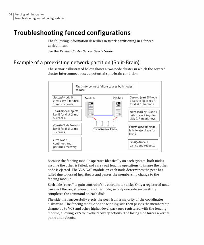
54 Fencing administration Troubleshooting fenced configurations
Troubleshooting fenced configurations The following information describes network partitioning in a fenced environment.
See the Veritas Cluster Server User’s Guide.
Example of a preexisting network partition (Split-Brain) The scenario illustrated below shows a two-node cluster in which the severed cluster interconnect poses a potential split-brain condition.
Second-Node 0 ejects key B for disk 1 and succeeds.
Node 0 Node 1
Coordinator Disks
Third-Node 0 ejects key B for disk 2 and succeeds.
Fourth-Node 0 ejects key B for disk 3 and succeeds.
Fifth-Node 0 continues and performs recovery.
Second (part B) Node 1 fails to eject key A for disk 1. Rereads
Third (part B)- Node 1 fails to eject keys for disk 2. Rereads keys.
Fourth (part B)-Node 1 fails to eject keys for disk 3.
Finally-Node 1 panics and reboots.
First-Interconnect failure causes both nodes to race.
Because the fencing module operates identically on each system, both nodes assume the other is failed, and carry out fencing operations to insure the other node is ejected. The VCS GAB module on each node determines the peer has failed due to loss of heartbeats and passes the membership change to the fencing module.
Each side “races” to gain control of the coordinator disks. Only a registered node can eject the registration of another node, so only one side successfully completes the command on each disk.
The side that successfully ejects the peer from a majority of the coordinator disks wins. The fencing module on the winning side then passes the membership change up to VCS and other higher-level packages registered with the fencing module, allowing VCS to invoke recovery actions. The losing side forces a kernel panic and reboots.

Fencing administration 55 Troubleshooting fenced configurations
Recovering from a Preexisting Network Partition (Split-Brain) The fencing module vxfen prevents a node from starting up after a network partition and subsequent panic and reboot of a node.
Example Scenario I Another scenario that could cause similar symptoms would be a two-node cluster with one node shut down for maintenance. During the outage, the private interconnect cables are disconnected.
Third-Node 0 has key registered on all coordinator disks.
Node 0 Node 1
Coordinator Disks
First-Network interconnect severed. Node 0 wins coordinator race
Second-Node 1 panics and reboots
Finally-Node 1 boots up and finds keys registered for non-member. Prints error message and exits.
In this scenario:
✔ Node 0 wins a coordinator race following to a network failure.
✔ Node 1 panics and reboots.
✔ Node 0 has keys registered on the coordinator disks. When node 1 boots up, it sees the Node 0 keys, but cannot see node 0 in the current GAB membership. It senses a potential preexisting split brain and causes the vxfen module to print an error message to the console. The vxfen module prevents fencing from starting, which, in turn, prevents VCS from coming online.
Suggested solution: Shut down Node 1, reconnect the cables, and restart Node 1.
Example Scenario II Similar to scenario I, if private interconnect cables are disconnected in a two-node cluster, Node 1 is fenced out of the cluster, panics, and reboots. If before the private interconnect cables are fixed and Node 1 rejoins the cluster, Node 0 panics and reboots (or just reboots). No node can write to the data disks until the private networks are fixed. This is because GAB membership cannot be formed, therefore the cluster cannot be formed.
Suggested solution: Shut down both nodes, reconnect the cables, restart the nodes.
56 Fencing administration Troubleshooting fenced configurations
Example Scenario III Similar to scenario II, if private interconnect cables are disconnected in a two-node cluster, Node 1 is fenced out of the cluster, panics, and reboots. If before the private interconnect cables are fixed and Node 1 rejoins the cluster, Node 0 panics due to hardware failure and cannot come back up, Node 1 cannot rejoin.
Suggested solution: Shut down Node 1, reconnect the cables, restart the node. You must then clear the registration of Node 0 from the coordinator disks.
1 On Node 1, type: # /opt/VRTSvcs/vxfen/bin/vxfenclearpre
2 Restart the node.
Chapter
5Veritas Volume Manager cluster functionality administration
A cluster consists of a number of hosts or nodes that share a set of disks. The main benefits of cluster configurations are:
■ Availability—If one node fails, the other nodes can still access the shared disks. When configured with suitable software, mission-critical applications can continue running by transferring their execution to a standby node in the cluster. This ability to provide continuous uninterrupted service by switching to redundant hardware is commonly termed failover.
Failover is transparent to users and high-level applications for database and file-sharing. You must configure cluster management software, such as VCS, to monitor systems and services, and to restart applications on another node in the event of either hardware or software failure. VCS also allows you to perform general administration tasks such as making nodes join or leave a cluster.
■ Off-host processing—Clusters can reduce contention for system resources by performing activities such as backup, decision support and report generation on the more lightly loaded nodes of the cluster. This allows businesses to derive enhanced value from their investment in cluster systems.
58 Veritas Volume Manager cluster functionality administration Overview of Cluster Volume Management
The CVM allows up to 32 nodes in a cluster to simultaneously access and manage a set of disks under VxVM control (VM disks). The same logical view of disk configuration and any changes to this is available on all the nodes. When the cluster functionality is enabled, all the nodes in the cluster can share VxVM objects. This chapter discusses the cluster functionality that is provided with VxVM.
For complete information on VxVM and CVM. Online versions of the VxVM documentation set are installed under the /opt/VRTS/docs directory.
See the Veritas Volume Manager Administrator’s Guide
For complete information on VCS. Online versions of the VCS documentation set are installed under the /opt/VRTS/docs directory.
See the Veritas Cluster Server User’s Guide.
Overview of Cluster Volume Management Tightly coupled cluster systems have become increasingly popular in enterprise-scale mission-critical data processing. The primary advantage of clusters is protection against hardware failure. If the primary node fails or otherwise becomes unavailable, applications can continue to run by transferring their execution to standby nodes in the cluster. This ability to provide continuous availability of service by switching to redundant hardware is commonly termed failover.
Another major advantage of clustered systems is their ability to reduce contention for system resources caused by activities such as backup, decision support and report generation. Enhanced value can be derived from cluster systems by performing such operations on lightly loaded nodes in the cluster instead of on the heavily loaded nodes that answer requests for service. This ability to perform some operations on the lightly loaded nodes is commonly termed load balancing.
To implement cluster functionality, VxVM works together with the cluster monitor daemon that is provided by the host operating system or by VCS. The cluster monitor informs VxVM of changes in cluster membership. Each node starts up independently and has its own cluster monitor plus its own copies of the operating system and VxVM with support for cluster functionality. When a node joins a cluster, it gains access to shared disks. When a node leaves a cluster, it no longer has access to shared disks. A node joins a cluster when the cluster monitor is started on that node.
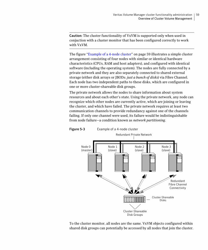
Veritas Volume Manager cluster functionality administration 59 Overview of Cluster Volume Management
Caution: The cluster functionality of VxVM is supported only when used in conjuction with a cluster monitor that has been configured correctly to work with VxVM.
The figure “Example of a 4-node cluster” on page 59 illustrates a simple cluster arrangement consisting of four nodes with similar or identical hardware characteristics (CPUs, RAM and host adapters), and configured with identical software (including the operating system). The nodes are fully connected by a private network and they are also separately connected to shared external storage (either disk arrays or JBODs: just a bunch of disks) via Fibre Channel. Each node has two independent paths to these disks, which are configured in one or more cluster-shareable disk groups.
The private network allows the nodes to share information about system resources and about each other’s state. Using the private network, any node can recognize which other nodes are currently active, which are joining or leaving the cluster, and which have failed. The private network requires at least two communication channels to provide redundancy against one of the channels failing. If only one channel were used, its failure would be indistinguishable from node failure—a condition known as network partitioning.
Figure 5-3 Example of a 4-node cluster
Redundant Private Network
Node 0 (master)
Node 1 (slave)
Node 2 (slave)
Node 3 (slave)
Redundant Fibre Channel Connectivity
Cluster-Shareable Disks
Cluster-Shareable Disk Groups
To the cluster monitor, all nodes are the same. VxVM objects configured within shared disk groups can potentially be accessed by all nodes that join the cluster.
60 Veritas Volume Manager cluster functionality administration Overview of Cluster Volume Management
However, the cluster functionality of VxVM requires that one node act as the master node; all other nodes in the cluster are slave nodes. Any node is capable of being the master node, and it is responsible for coordinating certain VxVM activities.
Note: You must run commands that configure or reconfigure VxVM objects on the master node. Tasks that must be initiated from the master node include setting up shared disk groups, creating and reconfiguring volumes, and performing snapshot operations.
VxVM designates the first node to join a cluster performs the function of the master node. If the master node leaves the cluster, one of the slave nodes is chosen to be the new master. In “Example of a 4-node cluster,” node 0 is the master node and nodes 1, 2 and 3 are slave nodes.
Private and shared disk Groups Two types of disk groups are defined:
■ Private disk groups—belong to only one node. A private disk group is only imported by one system. Disks in a private disk group may be physically accessible from one or more systems, but access is restricted to one system only. The boot disk group (usually aliased by the reserved disk group name bootdg) is always a private disk group.
■ Shared disk groups—shared by all nodes. A shared (or cluster-shareable) disk group is imported by all cluster nodes. Disks in a shared disk group must be physically accessible from all systems that may join the cluster.
In a cluster, most disk groups are shared. Disks in a shared disk group are accessible from all nodes in a cluster, allowing applications on multiple cluster nodes to simultaneously access the same disk. A volume in a shared disk group can be simultaneously accessed by more than one node in the cluster, subject to licensing and disk group activation mode restrictions.
You can use the vxdg command to designate a disk group as cluster-shareable.
See the Veritas Volume Manager Administrator’s Guide.
When a disk group is imported as cluster-shareable for one node, each disk header is marked with the cluster ID. As each node subsequently joins the cluster, it recognizes the disk group as being cluster-shareable and imports it. You can also import or deport a shared disk group at any time; the operation takes places in a distributed fashion on all nodes.
Veritas Volume Manager cluster functionality administration 61 Overview of Cluster Volume Management
Each physical disk is marked with a unique disk ID. When cluster functionality for VxVM starts on the master, it imports all shared disk groups (except for any that have the noautoimport attribute set). When a slave tries to join a cluster, the master sends it a list of the disk IDs that it has imported, and the slave checks to see if it can access them all. If the slave cannot access one of the listed disks, it abandons its attempt to join the cluster. If it can access all of the listed disks, it imports the same shared disk groups as the master and joins the cluster. When a node leaves the cluster, it deports all its imported shared disk groups, but they remain imported on the surviving nodes.
Reconfiguring a shared disk group is performed with the co-operation of all nodes. Configuration changes to the disk group happen simultaneously on all nodes and the changes are identical. Such changes are atomic in nature, which means that they either occur simultaneously on all nodes or not at all.
Whether all members of the cluster have simultaneous read and write access to a cluster-shareable disk group depends on its activation mode setting as discussed in “Activation modes of shared disk groups.” The data contained in a cluster-shareable disk group is available as long as at least one node is active in the cluster. The failure of a cluster node does not affect access by the remaining active nodes. Regardless of which node accesses a cluster-shareable disk group, the configuration of the disk group looks the same.
Note: Applications running on each node can access the data on the VM disks simultaneously. VxVM does not protect against simultaneous writes to shared volumes by more than one node. It is assumed that applications control consistency (by using a distributed lock manager, for example).
Activation modes of shared disk groups A shared disk group must be activated on a node for the volumes in the disk group to become accessible for I/O from that node. The ability of applications to read from or to write to volumes is determined by the activation mode of a shared disk group. Valid activation modes for a shared disk group are exclusive-write, read-only, shared-read, shared-write, and off (inactive). Activation modes are described in the table “Activation modes for shared disk groups” on page 62.
Note: The default activation mode for shared disk groups is shared-write.
Applications such as high availability and off-host backup can use disk group activation to explicitly control volume access from different nodes in the cluster.
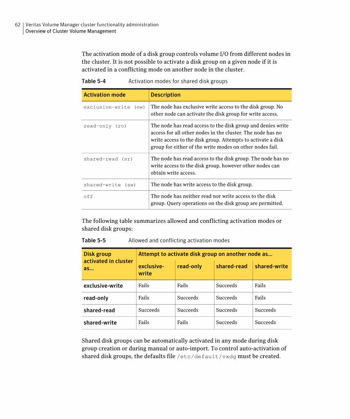
62 Veritas Volume Manager cluster functionality administration Overview of Cluster Volume Management
The activation mode of a disk group controls volume I/O from different nodes in the cluster. It is not possible to activate a disk group on a given node if it is activated in a conflicting mode on another node in the cluster.
Table 5-4 Activation modes for shared disk groups
Activation mode Description
exclusive-write (ew) The node has exclusive write access to the disk group. No other node can activate the disk group for write access.
read-only (ro) The node has read access to the disk group and denies write access for all other nodes in the cluster. The node has no write access to the disk group. Attempts to activate a disk group for either of the write modes on other nodes fail.
shared-read (sr) The node has read access to the disk group. The node has no write access to the disk group, however other nodes can obtain write access.
shared-write (sw) The node has write access to the disk group.
off The node has neither read nor write access to the disk group. Query operations on the disk group are permitted.
The following table summarizes allowed and conflicting activation modes or shared disk groups:
Table 5-5 Allowed and conflicting activation modes
Disk group activated in cluster as...
Attempt to activate disk group on another node as...
exclusive-write
read-only shared-read shared-write
exclusive-write Fails Fails Succeeds Fails
read-only Fails Succeeds Succeeds Fails
shared-read Succeeds Succeeds Succeeds Succeeds
shared-write Fails Fails Succeeds Succeeds
Shared disk groups can be automatically activated in any mode during disk group creation or during manual or auto-import. To control auto-activation of shared disk groups, the defaults file /etc/default/vxdg must be created.

Veritas Volume Manager cluster functionality administration 63 Overview of Cluster Volume Management
The defaults file /etc/default/vxdg must contain the following lines: enable_activation=true default_activation_mode=activation-mode
The activation-mode is one of exclusive-write, read-only, shared-read, shared-write, or off.
Caution: When enabling activation using the defaults file, it is advisable that the defaults file be identical on all nodes in the cluster. Otherwise, the results of activation are unpredictable.
When a shared disk group is created or imported, it is activated in the specified mode. When a node joins the cluster, all shared disk groups accessible from the node are activated in the specified mode.
If the defaults file is edited while the vxconfigd daemon is already running, the vxconfigd process must be restarted for the changes in the defaults file to take effect.
Caution: If the default activation mode is anything other than off, an activation following a cluster join, or a disk group creation or import can fail if another node in the cluster has activated the disk group in a conflicting mode.
To display the activation mode for a shared disk group, use the vxdg list diskgroup command.
You can also use the vxdg command to change the activation mode on a shared disk group.
Connectivity policy of shared disk groups The nodes in a cluster must always agree on the status of a disk. In particular, if one node cannot write to a given disk, all nodes must stop accessing that disk before the results of the write operation are returned to the caller. Therefore, if a node cannot contact a disk, it should contact another node to check on the disk’s status. If the disk fails, no node can access it and the nodes can agree to detach the disk. If the disk does not fail, but rather the access paths from some of the nodes fail, the nodes cannot agree on the status of the disk. Either of the following policies for resolving this type of discrepancy may be applied:
■ Under the global connectivity policy, the detach occurs cluster-wide (globally) if any node in the cluster reports a disk failure. This is the default policy.
64 Veritas Volume Manager cluster functionality administration Overview of Cluster Volume Management
■ Under the local connectivity policy, in the event of disks failing, the failures are confined to the particular nodes that saw the failure. Note that an attempt is made to communicate with all nodes in the cluster to ascertain the disks’ usability. If all nodes report a problem with the disks, a cluster-wide detach occurs.
The vxdg command can be used to set the disk dettach and dg fail policy. The dgfailpolicy sets the disk group failure policy in the case that the master node loses connectivity to the configuration and log copies within a shared disk group. This attribute requires that the disk group version is 120 or greater. The following policies are supported:
■ dgdisable—The master node disables the diskgroup for all user or kernel initiated transactions. First write and final close fail. This is the default policy.
■ leave—The master node panics instead of disabling the disk group if a log update fails for a user or kernel initiated transaction (including first write or final close). If the failure to access the log copies is global, all nodes panic in turn as they become the master node.
Disk group failure policy The local detach policy by itself is insufficient to determine the desired behavior if the master node loses access to all disks that contain copies of the configuration database and logs. In this case, the disk group is disabled. As a result, the other nodes in the cluster also lose access to the volume. In release 4.1, the disk group failure policy was introduced to determine the behavior of the master node in such cases. This policy has two possible settings as shown in the following table:
Table 5-6 Behavior of master node for different failure policies
Type of I/O failure Leave (dgfailpolicy=leave)
Disable (dgfailpolicy=dgdisable)
Master node loses The master node panics with The master node disables the access to all copies of the message “klog update disk group. the logs. failed” for a failed
kernel-initiated transaction, or “cvm config update failed” for a failed user-initiated transaction.
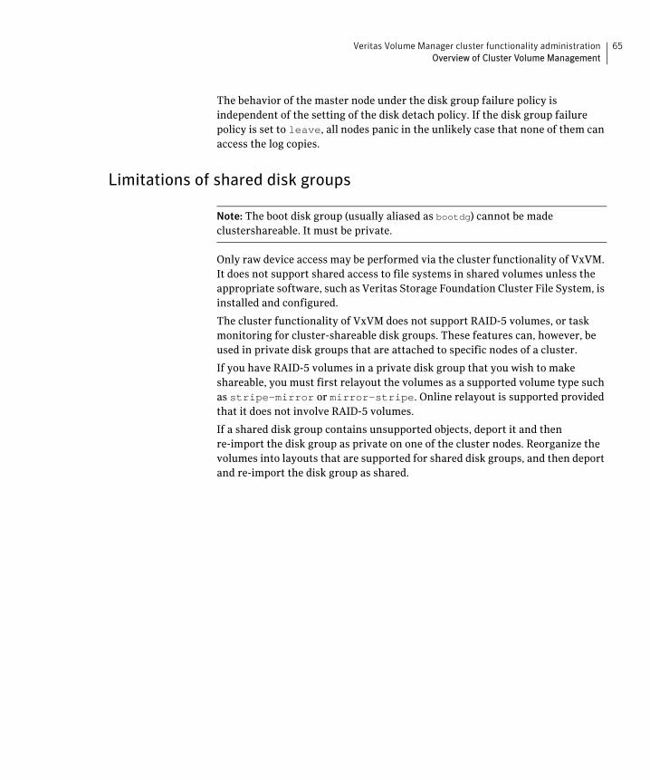
Veritas Volume Manager cluster functionality administration 65 Overview of Cluster Volume Management
The behavior of the master node under the disk group failure policy is independent of the setting of the disk detach policy. If the disk group failure policy is set to leave, all nodes panic in the unlikely case that none of them can access the log copies.
Limitations of shared disk groups
Note: The boot disk group (usually aliased as bootdg) cannot be made clustershareable. It must be private.
Only raw device access may be performed via the cluster functionality of VxVM. It does not support shared access to file systems in shared volumes unless the appropriate software, such as Veritas Storage Foundation Cluster File System, is installed and configured.
The cluster functionality of VxVM does not support RAID-5 volumes, or task monitoring for cluster-shareable disk groups. These features can, however, be used in private disk groups that are attached to specific nodes of a cluster.
If you have RAID-5 volumes in a private disk group that you wish to make shareable, you must first relayout the volumes as a supported volume type such as stripe-mirror or mirror-stripe. Online relayout is supported provided that it does not involve RAID-5 volumes.
If a shared disk group contains unsupported objects, deport it and then re-import the disk group as private on one of the cluster nodes. Reorganize the volumes into layouts that are supported for shared disk groups, and then deport and re-import the disk group as shared.

66 Veritas Volume Manager cluster functionality administration Overview of Cluster Volume Management

Chapter
6Agents for Storage Foundation Cluster File System
Agents are processes that manage predefined resource types. When an agent is �started, it obtains configuration information from the Veritas Cluster Server �(VCS). It then periodically monitors the resources and updates VCS with the �resource status. Typically agents:�
■ Bring resources online
■ Take resources offline
■ Monitor resources and report any state changes to VCS
VCS bundled agents are part of VCS and are installed when VCS is installed. The cluster functionality agents are add-on resources to VCS for the Veritas File System and Veritas Volume Manager (VxVM). Cluster functionality agents and resource types are part of the VRTScavf package and are configured when you run the cfscluster config command.
See the Veritas Cluster Server Bundled Agents Reference Guide.
PDF versions of this guide are located under the /opt/VRTS/docs directory.
Topics in this appendix include:�
■ List of Storage Foundation Cluster File System Agents
■ VCS Cluster Components
■ Modifying the Agents and Their Resources
■ Storage Foundation Cluster File System Administrative Interface
68 Agents for Storage Foundation Cluster File System List of Storage Foundation Cluster File System Agents
List of Storage Foundation Cluster File System Agents
The SFCFS agents include:
■ CFSMount Agent
■ CFSfsckd Agent
■ CVMCluster Agent
■ CVMVolDg Agent
VCS Cluster Components Resources, attributes, and service groups are components integral to cluster �functionality.�
See the Veritas Cluster Server User’s Guide.
Resources Resources are hardware or software entities, such as disks, volumes, file system mount points, network interface cards (NICs), IP addresses, applications, and databases. Resources work together to provide a service to clients in a client/server environment. Resource types are defined in the types.cf file by a collection of attributes. The VCS configuration file, main.cf, contains the values for the attributes of the resources. The main.cf file incorporates the resources listed in the types.cf by way of an include directive.
Attributes Attributes contain data regarding the cluster, nodes, service groups, resources, �resource types, and agents. A specified value for a given attribute configures the �resource to function in a specific way. By modifying the value of an attribute of a �resource, you change the way the VCS agent manages the resource. Each �attribute has a definition and a value. You define an attribute by specifying its �data type and dimension. Attributes also have default values that are assigned �when a value is not specified. �
Service Groups Service groups are comprised of related resources. When a service group is �brought online, all the resources within the group are brought online.�
Agents for Storage Foundation Cluster File System 69 Modifying the Agents and Their Resources
Modifying the Agents and Their Resources You can use the VCS Cluster Manager GUI, or enter VCS commands (the “ha” commands such as hastatus and haconf) from the command line, to modify the configuration of the resources managed by an agent. You can also edit the main.cf file directly, but you must reboot your system for the changes to take effect. An example main.cf file is located in the /etc/VRTSvcs/conf/sample_cvm directory.
It is advisable to use the Veritas Cluster Server GUI to administer your cluster �file system resources.�
See Veritas Cluster Server Installation Guide.
Resources and Service Groups for File System Cluster Functionality Managing cluster mounts through VCS requires various resources types, �resources, and service groups. The VCS resource types required for Veritas�Volume Manager cluster functionality (or CVM) are:�
■ CVMCluster
■ CVMVolDg
CVMCluster controls the overall operation of CVM. The agents of CVMCluster bring up the CVM cluster. Only one CVMCluster resource is required in a VCS environment. It is advisable to use the standard configuration procedure for CVM to add the CVMCluster resource. The procedure creates a service group named cvm and adds the resources to the configuration.
See “Storage Foundation Cluster File System Administrative Interface” on�page 70.�
The VCS resource types required for SFCFS functionality are:�
■ CFSfsckd
■ CFSMount
CFSfsckd is a mandatory resource type for SFCFS functionality. CFSfsckd agents start the cluster file system check (fsck command) daemon, vxfsckd, which must be running for a cluster mount to succeed. As with CVMCluster, only one resource instance is required for CFSfsckd. You add these resources using the SFCFS configuration process, which adds the resources to the cvm service group.
See “The cfscluster Command” on page 71.�
70 Agents for Storage Foundation Cluster File System Storage Foundation Cluster File System Administrative Interface
Each CVMVolDg resource controls one shared disk group, and one or more �shared volumes of that disk group. CVMVolDg resources enable the disk group �and set the disk group activation mode. Each CFSMount resource controls the �cluster mount of a shared volume on a specified mount point. CFSMount �resources also keep track of mount options associated with the mount points. �
These resource instances are not added automatically during the SFCFS �configuration; you must add them as required using the SFCFS cluster �administration commands. �
Note: That the CFSMount and CVMVolDg resources are not added to the cvm service group; those should be added to a different service group.
See “The cfsmntadm Command” on page 72.�
Resource and Service Group Dependencies Dependencies between resources and service groups specify the order in which the resource and service group are brought online and taken offline, which must be done in correct sequence. The various resources and service groups required for SFCFS must follow these dependency (or link) rules:
■ A CFSMount resource must depend on the corresponding CVMVolDg resource
■ A service group containing the CVMVolDg resource must depend on the cvm service group
Storage Foundation Cluster File System Administrative Interface
The SFCFS administrative interface provides an easy and convenient way to create resources required for SFCFS with the correct attributes and the correct links between them.
Agents for Storage Foundation Cluster File System 71 Storage Foundation Cluster File System Administrative Interface
Storage Foundation Cluster File System Resource Management Commands
As many as five VCS agents are required to manage cluster file system functionality. Each of these resources has several attributes and dependencies between them. To make resources easier to manage, five SFCFS administrative commands are provided. It is advisable to use only these commands to manage cluster file systems. The commands are:
■ cfscluster—cluster configuration command
■ cfsmntadm—adds, deletes, modifies, and sets policy on cluster mounted file systems
■ cfsdgadm—adds or deletes shared disk groups to/from a cluster configuration
■ cfsmount/cfsumount—mounts/unmounts a cluster file system on a shared volume
The cfscluster Command The cfscluster command is used primarily to configure and unconfigure CVM and SFCFS, and can be run from any node in the cluster. VCS must be started before you can run the cfscluster config command. The cfscluster config command adds all the resource type definitions and adds resource instances, one each of type CVMCluster and CFSfsckd. The cfscluster config command also brings the resources online, and cfscluster status can be used to query the status of VCS.
See “Resources and Service Groups for File System Cluster Functionality” on �page 69.�
The cfscluster unconfig command takes resources offline (except CFSMount resources) and removes all the resources and service groups that were used to manage the cluster file system.
See the cfscluster(1M) manual page.
You must manually take CFSMount resources offline (using the cfsumount command) before executing the cfscluster unconfig command.
72 Agents for Storage Foundation Cluster File System Storage Foundation Cluster File System Administrative Interface
The cfsmntadm Command One CVMVolDg and one CFSMount resource is required to control each cluster mount. You can use the cfsmntadm add to add these resources. The cfsmntadm command takes mount points, shared volumes, and shared disk groups as arguments. You can optionally specify a service group name. If a service group name is specified, the cfsmntadm command creates a new service group (if the service group is not already present) and makes it dependent on the cvm service group. If no service group name is specified, cfsmntadm add creates a default service group, cfs. The command next adds CVMVolDg to the specified service group and associates it with the specified disk group (if that kind of resource is not already present in the same service group). Subsequently, cfsmntadm add adds a CFSMount resource and links it with the CVMVolDg resource, then sets the appropriate values to the resource attributes. It is advisable to add all the mount points (that have their device in the same shared disk group) to the same service group.
See “Resources and Service Groups for File System Cluster Functionality” on �page 69.�
Using cfsmntadm, you can also add file system snapshots and Storage Checkpoints; delete, display, and modify resources; and set the primary election policy on a cluster mounted file system.
See the cfsmntadm(1M) manual page.
The cfsdgadm Command The cfsdgadm command is the administrative interface for shared disk groups. Using cfsdgadm, you can add a shared disk group to a cluster configuration, delete a shared disk group, modify the activation mode, or display the shared disk group’s configuration information. A shared disk group must already exist before being specified with cfsdgadm command.
See the cfsdgadm(1M) manual page.
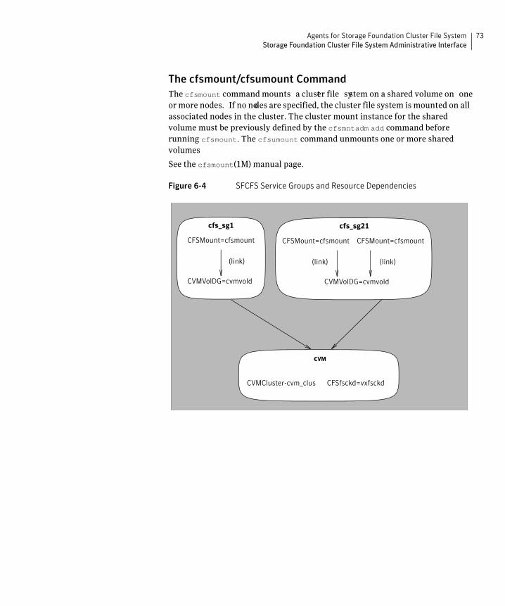
Agents for Storage Foundation Cluster File System 73 Storage Foundation Cluster File System Administrative Interface
The cfsmount/cfsumount Command The cfsmount command mounts a cluster file system on a shared volume on one or more nodes. If no nodes are specified, the cluster file system is mounted on all associated nodes in the cluster. The cluster mount instance for the shared volume must be previously defined by the cfsmntadm add command before running cfsmount. The cfsumount command unmounts one or more shared volumes
See the cfsmount(1M) manual page.
Figure 6-4 SFCFS Service Groups and Resource Dependencies
CVMVolDG=cvmvold
cfs_sg1
CFSMount=cfsmount
(link)
cVM
CVMCluster-cvm_clus CFSfsckd=vxfsckd
CVMVolDG=cvmvold
cfs_sg21
CFSMount=cfsmount
(link)
CFSMount=cfsmount
(link)
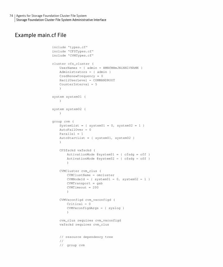
74 Agents for Storage Foundation Cluster File System Storage Foundation Cluster File System Administrative Interface
Example main.cf File
include "types.cf" include "CFSTypes.cf" include "CVMTypes.cf"
cluster cfs_cluster ( UserNames = { admin = HMNfMHmJNiNNlVNhMK } Administrators = { admin } CredRenewFrequency = 0 HacliUserLevel = COMMANDROOT CounterInterval = 5 )
system system01 ( )
system system02 ( )
group cvm ( SystemList = { system01 = 0, system02 = 1 } AutoFailOver = 0 Parallel = 1 AutoStartList = { system01, system02 } )
CFSfsckd vxfsckd ( ActivationMode @system01 = { cfsdg = off } ActivationMode @system02 = { cfsdg = off } )
CVMCluster cvm_clus ( CVMClustName = omcluster CVMNodeId = { system01 = 0, system02 = 1 } CVMTransport = gab CVMTimeout = 200 )
CVMVxconfigd cvm_vxconfigd ( Critical = 0 CVMVxconfigdArgs = { syslog } )
cvm_clus requires cvm_vxconfigdvxfsckd requires cvm_clus
// resource dependency tree//// group cvm

Agents for Storage Foundation Cluster File System 75 Storage Foundation Cluster File System Administrative Interface
// {// CFSfsckd vxfsckd// {// CVMClu ster cvm_clus// {// CV MVxconfigd cvm_vxconfigd// }// }// }
group vrts_vea_cfs_int_cfsmount1 ( SystemList = { system01 = 0, system02 = 1 } AutoFailOver = 0 Parallel = 1 AutoStartList = { system01, system02 } )
CFSMount cfsmount1 ( Critical = 0 MountPoint = "/mnt0" BlockDevice = "/dev/vx/dsk/cfsdg/vol1" NodeList = { system01 , system02 } RemountRes @system01 = DONE RemountRes @system02 = DONE )
CVMVolDg cvmvoldg1 ( Critical = 0 CVMDiskGroup = cfsdg CVMActivation @system01 = off CVMActivation @system02 = off )
requires group cvm online local firmcfsmount1 requires cvmvoldg1
// resource dependency tree//// group vrts_vea_cfs_int_cfsmount1// {// CFSMount cfsmount1// {// CVMVol Dg cvmvoldg1// }// }
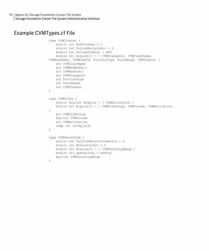
76 Agents for Storage Foundation Cluster File System Storage Foundation Cluster File System Administrative Interface
Example CVMTypes.cf File type CVMCluster (
static int NumThreads = 1 static int OnlineRetryLimit = 2 static int OnlineTimeout = 400 static str ArgList[] = { CVMTransport, CVMClustName,
CVMNodeAddr, CVMNodeId, PortConfigd, PortKmsgd, CVMTimeout } str CVMClustName str CVMNodeAddr{} str CVMNodeId{} str CVMTransport int PortConfigd int PortKmsgd int CVMTimeout
)
type CVMVolDg ( static keylist RegList = { CVMActivation } static str ArgList[] = { CVMDiskGroup, CVMVolume, CVMActivation
} str CVMDiskGroup keylist CVMVolume str CVMActivation temp int voldg_stat
)
type CVMVxconfigd ( static int FaultOnMonitorTimeouts = 2 static int RestartLimit = 5 static str ArgList[] = { CVMVxconfigdArgs } static str Operations = OnOnly keylist CVMVxconfigdArgs
)
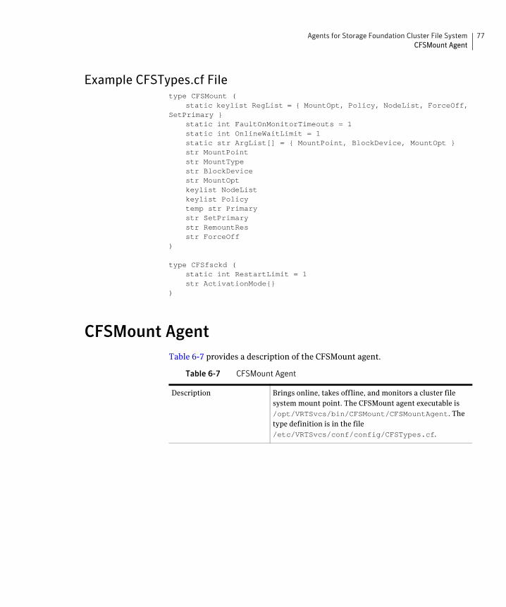
Agents for Storage Foundation Cluster File System 77 CFSMount Agent
Example CFSTypes.cf File type CFSMount (
static keylist RegList = { MountOpt, Policy, NodeList, ForceOff, SetPrimary }
static int FaultOnMonitorTimeouts = 1 static int OnlineWaitLimit = 1 static str ArgList[] = { MountPoint, BlockDevice, MountOpt } str MountPoint str MountType str BlockDevice str MountOpt keylist NodeList keylist Policy temp str Primary str SetPrimary str RemountRes str ForceOff
)
type CFSfsckd ( static int RestartLimit = 1 str ActivationMode{}
)
CFSMount Agent Table 6-7 provides a description of the CFSMount agent.
Table 6-7 CFSMount Agent
Description Brings online, takes offline, and monitors a cluster file system mount point. The CFSMount agent executable is /opt/VRTSvcs/bin/CFSMount/CFSMountAgent. The type definition is in the file /etc/VRTSvcs/conf/config/CFSTypes.cf.

78 Agents for Storage Foundation Cluster File System CFSMount Agent
Table 6-7 CFSMount Agent
Entry Points Online—Mounts a block device or file system snapshot in cluster mode.
Offline—Unmounts the file system (doing a forced unmount if necessary).
Monitor—Determines if the file system is mounted. Checks mount status using the fsclustadm command.
Clean—A null operation for a cluster file system mount.
attr_change—Remounts file system with new mount option; sets new primary for file system; sets fsclustadm policy on file system.
Required Attributes Type and Dimension
Definition
BlockDevice string-scalar Block device for mount point.
MountPoint string-scalar Directory for mount point.
NodeList string-keylist List of nodes on which to mount.
Optional Attributes Type and Dimension
Definition
Policy string-scalar Node list for the primary file system selection policy.

Agents for Storage Foundation Cluster File System 79 CFSMount Agent
Table 6-7 CFSMount Agent
MountOpt string-scalar Options for the mount command. To create a valid MountOpt attribute string:
■ Use VxFS type-specific options only.
■ Do not use the –o flag to specify the VxFS-specific options.
■ Do not use the –V vxfs file system type option.
■ The cluster option is not required.
■ Specify options in a comma-separated list as in these examples:
ro ro,cluster
blkclear,mincache=clo sesync
Internal Attributes
MountType, Primary, SetPrimary, RemountRes, ForceOff Not user-configured—used only by system.
Type Definition type CFSMount (
static int RestartLimit = 2 static str LogLevel static str ArgList[] = {MountPoint, BlockDevice, MountOpt} NameRule = resource.MountPoint str MountPoint str BlockDevice str MountOpt
)
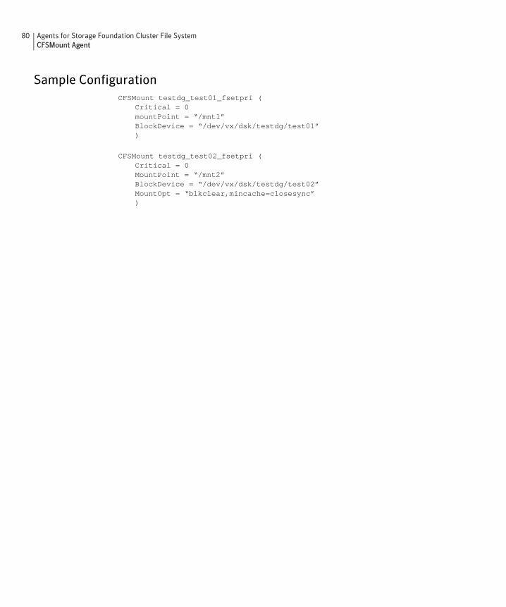
80 Agents for Storage Foundation Cluster File System CFSMount Agent
Sample Configuration CFSMount testdg_test01_fsetpri (
Critical = 0 mountPoint = “/mnt1” BlockDevice = “/dev/vx/dsk/testdg/test01” )
CFSMount testdg_test02_fsetpri ( Critical = 0 MountPoint = “/mnt2” BlockDevice = “/dev/vx/dsk/testdg/test02” MountOpt = “blkclear,mincache=closesync” )

Agents for Storage Foundation Cluster File System 81 CFSfsckd Agent
CFSfsckd Agent Table 6-8 provides a description of the CFSfsckd agent.
Table 6-8 CFSfsckd Agent
Description Starts, stops, and monitors the vxfsckd process. The CFSfsckd agent executable is /opt/VRTSvcs/bin/CFSfsckd/CFSfsckdAgent. The type definition is in the file /etc/VRTSvcs/conf/config/CFSTypes.cf. The configuration is added to the main.cf file after running the cfscluster config command.
Entry Points Online—Starts the vxfsckd process.
Offline—Kills the vxfsckd process.
Monitor—Checks whether the vxfsckd process is running.
Clean—A null operation for a cluster file system mount.
Required Attributes
Type and Dimension
Definition
None
Optional Attributes
Type and Dimension
Definition
None
Type Definition type CFSfsckd (
static int RestartLimit = 2 static str LogLevel static str ArgList[] = { } NameRule = ““
)
Sample Configuration CFSfsckd vxfsckd ( )

82 Agents for Storage Foundation Cluster File System CVMCluster Agent
CVMCluster Agent Table 6-9 provides a description of the CFSCluster agent.
Table 6-9 CVMCluster Agent
Description Controls node membership on the cluster port associated with CVM. The CVMCluster resource requires the CVMMultiNIC resource and must be configured to depend on CVMMultiNIC. The CVMCluster agent executable is /opt/VRTSvcs/bin/CVMCluster/CVMClusterAgent. The type definition is in the file /etc/VRTSvcs/conf/config/CVMTypes.cf. The configuration is added to the main.cf file after running the cfscluster config command.
Entry Points ■ Online—Joins a node to the CVM cluster port.
■ Offline—Removes a node from the CVM cluster port.
■ Monitor—Monitors the node’s CVM cluster membership state.
■ Clean—A null operation for a cluster file system mount.
Required Attributes
Type and Dimension
Definition
CVMClustName string-scalar Name of the cluster.
CVMNodeAddr string-associ ation
List of host names and IP addresses.
CVMNodeId string-associ ation
List of host names and LLT node numbers.
CVMTransport string-associ ation
The CVM transport mode, either gab or udp. For SFCFS, gab is the only valid transport mode.
PortConfigd integer-scalar Port number used by CVM for vxconfigd-level communication.
PortKmsgd integer-scalar Port number used by CVM for kernel-level communication.
CVMTimeout integer-scalar Timeout used by CVM during cluster reconfigurations.
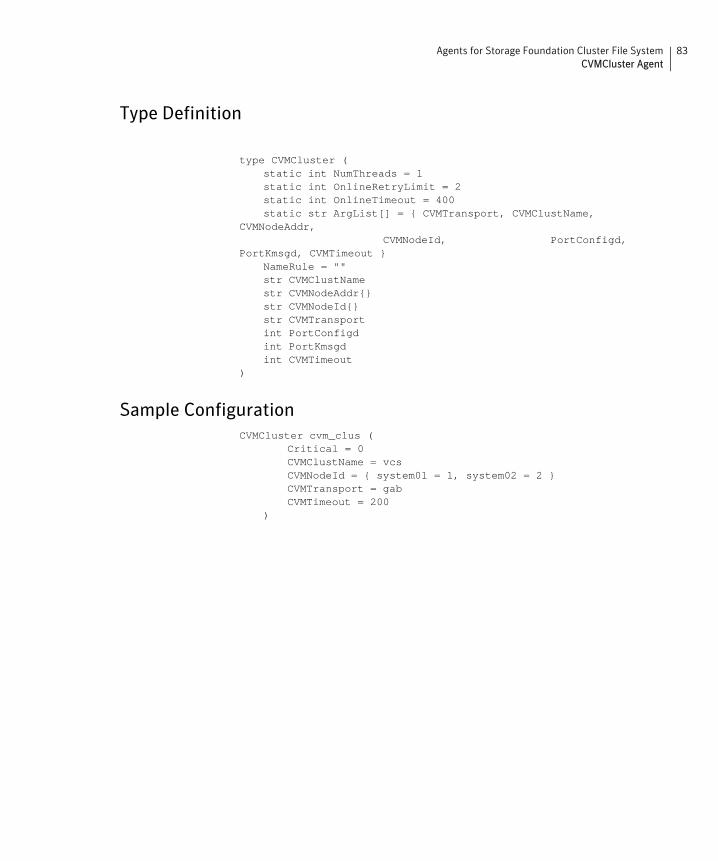
Agents for Storage Foundation Cluster File System 83 CVMCluster Agent
Type Definition
type CVMCluster ( static int NumThreads = 1 static int OnlineRetryLimit = 2 static int OnlineTimeout = 400 static str ArgList[] = { CVMTransport, CVMClustName,
CVMNodeAddr, CVMNodeId,
PortKmsgd, CVMTimeout } NameRule = "" str CVMClustName str CVMNodeAddr{} str CVMNodeId{} str CVMTransport int PortConfigd int PortKmsgd int CVMTimeout
)
Sample Configuration CVMCluster cvm_clus (
Critical = 0 CVMClustName = vcs
PortConfigd,
CVMNodeId = { system01 = 1, system02 = 2 } CVMTransport = gab CVMTimeout = 200
)

84 Agents for Storage Foundation Cluster File System CVMVolDg Agent
CVMVolDg Agent Table 6-10 provides a description of the CVMVolDg agent.
Table 6-10 CVMVolDg Agent
Description Brings online, takes offline, and monitors a VxVM shared volume in a disk group. The CVMVolDg agent executable is /opt/VRTSvcs/bin/CVMVolDg/CVMVolDg. The type definition is in the file /etc/VRTSvcs/conf/config/CVMTypes.cf.
Entry Points ■ Online—Sets the activation mode of the shared disk group and brings volumes online.
■ Offline—Sets the activation mode of the shared disk group to “off.”
■ Monitor—Determines whether the disk group and volumes are online.
■ Clean—A null operation for a cluster file system mount.
■ attr_changed—Changes the activation mode of the shared disk groups specified.
Required Attributes
Type and Dimension
Definition
CVMDiskGroup string-scalar Shared disk group name.
CVMVolume string-keylist Shared volume names.
CVMActivation string-scalar Activation mode for the disk group. Must be set to shared-write (sw). This is a localized attribute.
Type Definition type CVMVolDg (
static keylist RegList = { CVMActivation } static str ArgList[] = { CVMDiskGroup, CVMActivation } NameRule = "" str CVMDiskGroup str CVMActivation
)
Sample Configuration CVMVolDg testdg (
CVMDiskGroup = testdg CVMActivation @system01 = sw CVMActivation @system02 = sw )
Glossary
access control list (ACL)
The information that identifies specific users or groups and their access privileges for a particular file or directory.
agent
A process that manages predefined Veritas Cluster Server (VCS) resource types. Agents bring resources online, take resources offline, and monitor resources to report any state changes to VCS. When an agent is started, it obtains configuration information from VCS and periodically monitors the resources and updates VCS with the resource status.
allocation unit
A group of consecutive blocks on a file system that contain resource summaries, free resource maps, and data blocks. Allocation units also contain copies of the super-block.
API
Application Programming Interface.
asynchronous writes
A delayed write in which the data is written to a page in the system’s page cache, but is not written to disk before the write returns to the caller. This improves performance, but carries the risk of data loss if the system crashes before the data is flushed to disk.
atomic operation
An operation that either succeeds completely or fails and leaves everything as it was before the operation was started. If the operation succeeds, all aspects of the operation take effect at once and the intermediate states of change are invisible. If any aspect of the operation fails, then the operation aborts without leaving partial changes.
Block-Level Incremental Backup (BLI Backup)
A Veritas backup capability that does not store and retrieve entire files. Instead, only the data blocks that have changed since the previous backup are backed up.
boot disk
A disk that is used for the purpose of booting a system.
boot disk group
A private disk group that contains the disks from which the system may be booted.
bootdg
A reserved disk group name that is an alias for the name of the boot disk group.
buffered I/O
During a read or write operation, data usually goes through an intermediate kernel buffer before being copied between the user buffer and disk. If the same data is repeatedly read or written, this kernel buffer acts as a cache, which can improve performance.
86
See unbuffered I/O and direct I/O.
cluster mounted file system
A shared file system that enables multiple hosts to mount and perform file operations on the same file. A cluster mount requires a shared storage device that can be accessed by other cluster mounts of the same file system. Writes to the shared device can be done concurrently from any host on which the cluster file system is mounted. To be a cluster mount, a file system must be mounted using the mount –o cluster option.
See local mounted file system.
Cluster Services
The group atomic broadcast (GAB) module in the SFCFS stack provides cluster membership services to the file system. LLT provides kernel-to-kernel communications and monitors network communications.
See “The role of component products” on page 15.
contiguous file
A file in which data blocks are physically adjacent on the underlying media.
CVM
The cluster functionality of Veritas Volume Manager.
CVM Master
The cluster volume manager (CVM) has a master node that records changes to the volume configuration.
data block
A block that contains the actual data belonging to files and directories.
data synchronous writes
A form of synchronous I/O that writes the file data to disk before the write returns, but only marks the inode for later update. If the file size changes, the inode will be written before the write returns. In this mode, the file data is guaranteed to be on the disk before the write returns, but the inode modification times may be lost if the system crashes.
defragmentation
The process of reorganizing data on disk by making file data blocks physically adjacent to reduce access times.
direct extent
An extent that is referenced directly by an inode.
direct I/O
An unbuffered form of I/O that bypasses the kernel’s buffering of data. With direct I/O, the file system transfers data directly between the disk and the user-supplied buffer.
See buffered I/O and unbuffered I/O.
discovered direct I/O
Discovered Direct I/O behavior is similar to direct I/O and has the same alignment constraints, except writes that allocate storage or extend the file size do not require writing the inode changes before returning to the application.
encapsulation
87
A process that converts existing partitions on a specified disk to volumes. If any partitions contain file systems, /etc/filesystems entries are modified so that the file systems are mounted on volumes instead. Encapsulation is not applicable on some systems.
extent
A group of contiguous file system data blocks treated as a single unit. An extent is defined by the address of the starting block and a length.
extent attribute
A policy that determines how a file allocates extents.
external quotas file
A quotas file (named quotas) must exist in the root directory of a file system for quota-related commands to work.
See quotas file and internal quotas file.
file system block
The fundamental minimum size of allocation in a file system. This is equivalent to the fragment size on some UNIX file systems.
fileset
A collection of files within a file system.
fixed extent size
An extent attribute used to override the default allocation policy of the file system and set all allocations for a file to a specific fixed size.
fragmentation
The on-going process on an active file system in which the file system is spread further and further along the disk, leaving unused gaps or fragments between areas that are in use. This leads to degraded performance because the file system has fewer options when assigning a file to an extent.
GB
Gigabyte (230 bytes or 1024 megabytes).
hard limit
The hard limit is an absolute limit on system resources for individual users for file and data block usage on a file system.
See quota.
Heartbeats
Heartbeat messages are sent over the private link to obtain information on clustermembership changes. If a node does not send a heartbeat for 16 seconds, it is removed from the membership. The command lltconfig is used for information on the various heartbeat parameters. The low latency transport (LLT) module provides communicationservices across the cluster.
indirect address extent
An extent that contains references to other extents, as opposed to file data itself. A singleindirect address extent references indirect data extents. A double indirect address extent references single indirect address extents.
indirect data extent
88
An extent that contains file data and is referenced via an indirect address extent.
inode
A unique identifier for each file within a file system that contains the data and metadata associated with that file.
inode allocation unit
A group of consecutive blocks containing inode allocation information for a given fileset. This information is in the form of a resource summary and a free inode map.
intent logging
A method of recording pending changes to the file system structure. These changes are recorded in a circular intent log file.
internal quotas file
VxFS maintains an internal quotas file for its internal usage. The internal quotas file maintains counts of blocks and indices used by each user.
See quotas and external quotas file.
K
Kilobyte (210 bytes or 1024 bytes).
large file
A file larger than one terabyte. VxFS supports files up to 8 exabytes in size.
large file system
A file system larger than one terabytes. VxFS supports file systems up to 8 exabytes in size.
latency
For file systems, this typically refers to the amount of time it takes a given file system operation to return to the user.
local mounted file system
A file system mounted on a single host. The single host mediates all file system writes to storage from other clients. To be a local mount, a file system cannot be mounted using the mount –o cluster option.
See cluster mounted file system.
metadata
Structural data describing the attributes of files on a disk.
MB
Megabyte (220 bytes or 1024 kilobytes).
mirror
A duplicate copy of a volume and the data therein (in the form of an ordered collection of subdisks). Each mirror is one copy of the volume with which the mirror is associated.
multi-volume file system
A single file system that has been created over multiple volumes, with each volume having its own properties.
MVS
Multi-volume support.
89
node
One of the hosts in a cluster.
node abort
A situation where a node leaves a cluster (on an emergency basis) without attempting to stop ongoing operations.
node join
The process through which a node joins a cluster and gains access to shared disks.
object location table (OLT)
The information needed to locate important file system structural elements. The OLT is written to a fixed location on the underlying media (or disk).
object location table replica
A copy of the OLT in case of data corruption. The OLT replica is written to a fixed location on the underlying media (or disk).
page file
A fixed-size block of virtual address space that can be mapped onto any of the physical addresses available on a system.
preallocation
A method of allowing an application to guarantee that a specified amount of space is available for a file, even if the file system is otherwise out of space.
primary fileset
The files that are visible and accessible to the user.
Quick I/O file
A regular VxFS file that is accessed using the ::cdev:vxfs: extension.
Quick I/O for Databases
Quick I/O is a Veritas File System feature that improves database performance by minimizing read/write locking and eliminating double buffering of data. This allows online transactions to be processed at speeds equivalent to that of using raw disk devices, while keeping the administrative benefits of file systems.
quotas
Quota limits on system resources for individual users for file and data block usage on a file system.
See hard limit and soft limit.
quotas file
The quotas commands read and write the external quotas file to get or change usage limits. When quotas are turned on, the quota limits are copied from the external quotas file to the internal quotas file.
See quotas, internal quotas file, and external quotas file.
reservation
An extent attribute used to preallocate space for a file.
root disk group
90
A special private disk group that always exists on the system. The root disk group is named rootdg.
SFCFS
The Veritas Storage Foundation Cluster File System.
SFCFS Primary
There is a primary node for each file system in the cluster responsible for updating metadata in the file system.
shared disk group
A disk group in which the disks are shared by multiple hosts (also referred to as a cluster-shareable disk group).
shared volume
A volume that belongs to a shared disk group and is open on more than one node at the same time.
snapshot file system
An exact copy of a mounted file system at a specific point in time. Used to do online backups.
snapped file system
A file system whose exact image has been used to create a snapshot file system.
soft limit
The soft limit is lower than a hard limit. The soft limit can be exceeded for a limited time. There are separate time limits for files and blocks.
See hard limit and quotas.
Storage Checkpoint
A facility that provides a consistent and stable view of a file system or database image and keeps track of modified data blocks since the last Storage Checkpoint.
structural fileset
The files that define the structure of the file system. These files are not visible or accessible to the user.
super-block
A block containing critical information about the file system such as the file system type, layout, and size. The VxFS super-block is always located 8192 bytes from the beginning of the file system and is 8192 bytes long.
synchronous writes
A form of synchronous I/O that writes the file data to disk, updates the inode times, and writes the updated inode to disk. When the write returns to the caller, both the data and the inode have been written to disk.
TB
Terabyte (240 bytes or 1024 gigabytes).
transaction
Updates to the file system structure that are grouped together to ensure they are all completed.
91
throughput
For file systems, this typically refers to the number of I/O operations in a given unit of time.
unbuffered I/O
I/O that bypasses the kernel cache to increase I/O performance. This is similar to direct I/O, except when a file is extended; for direct I/O, the inode is written to disk synchronously, for unbuffered I/O, the inode update is delayed.
See buffered I/O and direct I/O.
VCS
The Veritas Cluster Server.
volume
A virtual disk which represents an addressable range of disk blocks used by applications such as file systems or databases.
volume set
A container for multiple different volumes. Each volume can have its own geometry.
vxfs
The Veritas File System type. Used as a parameter in some commands.
VxFS
The Veritas File System.
VxVM
The Veritas Volume Manager.

92

Index
Symbols /etc/default/vxdg defaults file 62/etc/default/vxdg file 29
A activating resources for CFS 71activation modes for shared disk groups 28, 61agents
CFS 36, 67CFSfsckd 81CFSMount 77, 81CVM 67CVMCluster 82CVMQlogckd 82CVMVolDg 84modifying 69VCS 67VCS bundled 67
asymmetric mounts 18, 35attributes defined 68
CFSactivating resources 71agents 36, 67applications 13cluster mounts 34load distribution 21, 38memory mapping 10modifying resources 71overview 34snapshots 20, 39supported features 10synchronization 21, 37using commands 36
cfscluster command 36, 71cfsdgadm command 36, 71CFSfsckd agent 81cfsmntadm command 36, 71CFSMount agent 77, 81
CFSTypes.cf file 77CFSTypes.cf file example 77cluster mounted file systems 34clusters
activating disk groups 29, 62activation modes for shared disk groups 28, 61benefits 57cluster-shareable disk groups 27, 60designating shareable disk groups 27, 60global connectivity policy 30, 63limitations of shared disk groups 30, 65local connectivity policy 30, 64maximum number of nodes in 58nodes 25, 58private disk groups 27, 60private networks 25, 59protection against simultaneous writes 28, 61resolving disk status in 30, 63shared disk groups 27, 60shared objects 61
cluster-shareable disk groups in clusters 27, 60commands
cfscluster 36, 71cfsdgadm 36, 71cfsmntadm 36, 71
configuration filesCFSTypes.cf 77CVMTypes.cf 76main.cf 74modifying 69types.cf 68
connectivity policiesglobal 30, 63local 30, 64
coordinator disks definition of 44
creating resource and service groups 72CVM
agents 67cluster functionality of VxVM 57
CVM overview 34CVMCluster agent 82
C
94
CVMQlogckd agent 82CVMTypes.cf file 76CVMTypes.cf file example 76CVMVolDg agent 84
D dependencies of resource and service groups 70disable failure policy 64disk groups
activation in clusters 29, 62cluster-shareable 27, 60defaults file for shared 29, 62designating as shareable 27, 60failure policy 64global connectivity policy for shared 30, 63local connectivity policy for shared 30, 64private in clusters 27, 60shared in clusters 27, 60
disks, resolving status in clusters 30, 63
E established 10exclusive-write mode 28, 61exclusivewrite mode 28
F failover 57, 58failure policies 64file systems
CFSMount agent monitoring 77fsclustadm
how to determine a cluster file system primary 35, 38
how to set a cluster file system primary 35fstab file, using with CFS 38fstyp, using to determine the disk layout version 10
G GAB description 15, 33gabtab file description 15, 33GLM description 17GUI
Cluster Manager 39VEA 39
H how to determine a cluster file system primary 38how to determine a CVM master node 38how to determine the disk layout version 10
II/O fencing
definition of 43disabling 50scenarios for 50
K keys
registration keys, formatting of 49
L leave failure policy 64LLT description 16, 33llttab file description 16, 33load balancing 58LUNs, using for coordinator disks 45
M main.cf file
example 74managing resource and service groups 69master node 26, 60modifying agents 69
N network partition 25, 59nodes
in clusters 25, 58maximum number in a cluster 58
NTP, network time protocol daemon 21, 37
O off-host processing 57
P primaryship, setting with fsclustadm 38private disk groups in clusters 27, 60private networks in clusters 25, 59

95
R read-only mode 28, 61readonly mode 28registration key
displaying with vxfenadm 49formatting of 49
registrationskey formatting 49
resource and service groupscreating 72defined 68dependencies 70managing 69
S service groups 68shared disk groups
activation modes 28, 61in clusters 27, 60limitations of 30, 65
shared-read mode 28, 61sharedread mode 28shared-write mode 28, 61sharedwrite mode 28slave nodes 26, 60
T types.cf file 68
VCSattributes 68bundled agents 67configuration files
CFSTypes.cf 77main.cf 74
VCS overview 15, 33vxdctl
how to determine a CVM master node 38vxfenadm command
options for administrators 49vxfentab file
created by rc script 47vxfentsthdw
testing disks 47VxVM
cluster functionality (CVM) 57
limitations of shared disk groups 30, 65shared objects in cluster 61
V

96


