STORES SEPARATION FROM WEAPONS BAYS Malcolm Tutty, JAIME Enterprises Australia Pty Ltd, and Graham Akroyd, Akroyd Aeronautics, Australia Alex Cenko and Alfred Piranian, AIWS LLC, USA Keywords: aircraft stores compatibility and separations,interoperability, systems of systems, information age Abstract The difficulty in using any method to predict the carriage and subsequent release of a weapon is not only in an ability to accurately simulate the complex component interactions, but also in providing this information quickly enough to authorize the clearance of the weapon. An Integrated Test and Evaluation (T&E) approach to store separation was introduced that combined wind tunnel testing, analysis methods, and flight testing almost two decades ago. CFD, which was only occasionally used at that time, now has often replaced the wind tunnel for external store separation. Many current and all new attack aircraft, both manned and unmanned, are designed for internal weapons carriage. The problems of using CFD, wind tunnel and flight test for aircraft stores separation from internal weapons bays are described. 1.0 Introduction In an attempt to minimise the time and cost of the flight certification process advanced Computational Fluid Dynamic (CFD) methods to support and supplement wind tunnel and flight testing were developed [1, 2, 3, 4]. CFD methods were also used for older aircraft, where no sub-scale wind tunnel models were available [5]. Over the past quarter of a century, the US Air Force, Army and Navy, Royal Australian Air Force (RAAF), and Royal Canadian Air Force, amongst others primarily in Europe, have made concerted efforts to accelerate the validation and verification necessary to enable the insertion of the latest CFD methods into the aircraft stores certification process. A cooperative effort between the US Air Force, Army and Navy to called “Improvement of High Performance Computing (HPC) Applications to Air Armament was instituted by the US Department of Defence (DOD) in 2002. One project was to determine if CFD could predict store trajectories from bomb bays [6]. The results of this effort helped develop the approach to support of the store separation flight clearance for the P-8A aircraft. Aircraft stores separation forms a key part of establishing the compatibility of an aircraft stores configuration i to be operationally suitable and effective to perform testing, training and conduct operations. Traditionally the Five Eyes and many NATO nations use MIL-HDBK-1763 [7], MIL-HDBK-244A [8], NATO STANAG 7068 [9] and Science and Technology (STO) AGARDOgraph 300 Vol 29 [10] as the basis for conducting modeling and simulation (M&S), laboratory qualification wind tunnel tests prior to ground and flight experimentation, and T&E (ET&E) to establish the certification basis and degree of interoperability for the aircraft stores configurations needed. This is discussed in detail as it pertains to external and internal weapons separation at [11]. This paper will explore the implications of this on internal separations and then the key implications for the use of such future technology and changes in methodologies for the profession of arms ii in the Information Age [12] as there is no accepted international experimentation or Validation & Verification/T&E framework for today’s stand-alone systems iii or system of systems (SoS) iv let alone future network- enabled, complex, adaptive capabilities employing kinetic and increasingly 1
Transcript
STORES SEPARATION FROM WEAPONS BAYS
Malcolm Tutty, JAIME Enterprises Australia Pty Ltd, and Graham Akroyd, Akroyd Aeronautics, Australia
Alex Cenko and Alfred Piranian, AIWS LLC, USA
Keywords: aircraft stores compatibility and separations,interoperability, systems of systems, information age
Abstract
The difficulty in using any method to predict the carriage and subsequent release of a weapon is not only in an ability to accurately simulate the complex component interactions, but also in providing this information quickly enough to authorize the clearance of the weapon. An Integrated Test and Evaluation (T&E) approach to store separation was introduced that combined wind tunnel testing, analysis methods, and flight testing almost two decades ago. CFD, which was only occasionally used at that time, now has often replaced the wind tunnel for external store separation. Many current and all new attack aircraft, both manned and unmanned, are designed for internal weapons carriage. The problems of using CFD, wind tunnel and flight test for aircraft stores separation from internal weapons bays are described.
1.0 Introduction
In an attempt to minimise the time and cost of the flight certification process advanced Computational Fluid Dynamic (CFD) methods to support and supplement wind tunnel and flight testing were developed [1, 2, 3, 4]. CFD methods were also used for older aircraft, where no sub-scale wind tunnel models were available [5].
Over the past quarter of a century, the US Air Force, Army and Navy, Royal Australian Air Force (RAAF), and Royal Canadian Air Force, amongst others primarily in Europe, have made concerted efforts to accelerate the validation and verification necessary to enable the insertion of the latest CFD methods into the aircraft stores certification process.
A cooperative effort between the US Air Force, Army and Navy to called “Improvement of High Performance Computing (HPC) Applications to Air Armament was instituted by the US Department of Defence (DOD) in 2002. One project was to determine if CFD could predict store trajectories from bomb bays [6]. The results of this effort helped develop the approach to support of the store separation flight clearance for the P-8A aircraft.
Aircraft stores separation forms a key part of establishing the compatibility of an aircraft stores configuration i to be operationally suitable and effective to perform testing, training and conduct operations. Traditionally the Five Eyes and many NATO nations use MIL-HDBK-1763 [7], MIL-HDBK-244A [8], NATO STANAG 7068 [9] and Science and Technology (STO) AGARDOgraph 300 Vol 29 [10] as the basis for conducting modeling and simulation (M&S), laboratory qualification wind tunnel tests prior to ground and flight experimentation, and T&E (ET&E) to establish the certification basis and degree of interoperability for the aircraft stores configurations needed. This is discussed in detail as it pertains to external and internal weapons separation at [11]. This paper will explore the implications of this on internal separations and then the key implications for the use of such future technology and changes in methodologies for the profession of armsii in the Information Age [12] as there is no accepted international experimentation or Validation & Verification/T&E framework for today’s stand-alone systems iii or system of systems (SoS) iv let alone future network-enabled, complex, adaptive capabilities employing kinetic and increasingly
1
TUTTY, CENKO, AKROYD, PIRANIAN
non-kinetic electronic and cyber effects in the likely threat scenarios requiring joint fires.v
2.0 P-8A Poseidon Aircraft
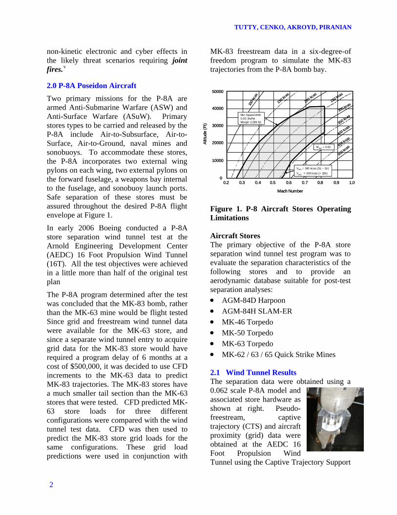
Two primary missions for the P-8A are armed Anti-Submarine Warfare (ASW) and Anti-Surface Warfare (ASuW). Primary stores types to be carried and released by the P-8A include Air-to-Subsurface, Air-to-Surface, Air-to-Ground, naval mines and sonobuoys. To accommodate these stores, the P-8A incorporates two external wing pylons on each wing, two external pylons on the forward fuselage, a weapons bay internal to the fuselage, and sonobuoy launch ports. Safe separation of these stores must be assured throughout the desired P-8A flight envelope at Figure 1.
In early 2006 Boeing conducted a P-8A store separation wind tunnel test at the Arnold Engineering Development Center (AEDC) 16 Foot Propulsion Wind Tunnel (16T). All the test objectives were achieved in a little more than half of the original test plan
The P-8A program determined after the test was concluded that the MK-83 bomb, rather than the MK-63 mine would be flight tested Since grid and freestream wind tunnel data were available for the MK-63 store, and since a separate wind tunnel entry to acquire grid data for the MK-83 store would have required a program delay of 6 months at a cost of $500,000, it was decided to use CFD increments to the MK-63 data to predict MK-83 trajectories. The MK-83 stores have a much smaller tail section than the MK-63 stores that were tested. CFD predicted MK-63 store loads for three different configurations were compared with the wind tunnel test data. CFD was then used to predict the MK-83 store grid loads for the same configurations. These grid load predictions were used in conjunction with
MK-83 freestream data in a six-degree-of freedom program to simulate the MK-83 trajectories from the P-8A bomb bay.
300 kcas
350 kcas
400 kcas
450 kcas
500 kcas
250 kcas
0.2 0.3 0.4 0.5 0.6 0.7 0.8 0.9 1.00
10000
20000
30000
40000
50000
Mach Number
Alti
tude
(Ft
)
100
kcas
150 kc
as
200 kcas
Min Speed With 0.3G Buffet Margin (130k lb)
VMO = 360 kcas (SL – 1k)
VMO = 340 kcas (> 10k)
MMO = 0.82
300 kcas
350 kcas
400 kcas
450 kcas
500 kcas
250 kcas
0.2 0.3 0.4 0.5 0.6 0.7 0.8 0.9 1.00
10000
20000
30000
40000
50000
Mach Number
Alti
tude
(Ft
)
100
kcas
150 kc
as
200 kcas
Min Speed With 0.3G Buffet Margin (130k lb)
VMO = 360 kcas (SL – 1k)
VMO = 340 kcas (> 10k)
MMO = 0.82
Figure 1. P-8 Aircraft Stores Operating Limitations Aircraft Stores The primary objective of the P-8A store separation wind tunnel test program was to evaluate the separation characteristics of the following stores and to provide an aerodynamic database suitable for post-test separation analyses:
AGM-84D Harpoon
AGM-84H SLAM-ER
MK-46 Torpedo
MK-50 Torpedo
MK-63 Torpedo
MK-62 / 63 / 65 Quick Strike Mines 2.1 Wind Tunnel Results The separation data were obtained using a 0.062 scale P-8A model and associated store hardware as shown at right. Pseudo-freestream, captive trajectory (CTS) and aircraft proximity (grid) data were obtained at the AEDC 16 Foot Propulsion Wind Tunnel using the Captive Trajectory Support
2
ICAS 2016-0156
(CTS) system. P-8A pseudo-freestream data (freestream data with the aircraft present in the tunnel) were also obtained at constant yaw angles at selected Mach number and angle of attack combinations. A digital computer routine used the balance-measured loads and other pertinent physical, ejector, thrust, or controls data to compute the time-variant separation trajectory for the CTS runs. Grid data were obtained along pre-selected rays emanating from the store carriage point. Internal weapons bay testing utilized both strut- and sting-mounted stores to permit surveys within the bay without contacting the aircraft and or support equipment. External stores used a sting support only.
Figure 2 Strut and Sting Mounted MK-63 Stores 2.1.1 Freestream data
Both strut and sting-mounted wind tunnel freestream data were acquired for the MK-63 mine to determine the effects of the mounting system on the store aerodynamic characteristics.
As may be seen in Figure 3, there is little difference in the Normal Force (CN) values at low store angle of attack (Alphas) for M = 0.85. The Pitching Moment (CLM) values
for the strut match the sting data by subtracting out an offset coefficient of 0.2. Since all the trajectory simulations use incremental grid data (grid data with the freestream values subtracted out), these differences should have no impact on the trajectory predictions. However, there is a large discrepancy in Side Force (CY) and Yawing moment (CLN) at store sideslip angle (Betas) of -5 degrees, which increases with increasing Alphas, Figure 3. Only these four aerodynamic coefficients are considered important, since axial force (CA) and rolling moment (CLL) have little effect on store trajectories. This was not unexpected, since the strut mounting was expected to affect the forces and moments in the yaw plane. Clearly, strut mounted data at yaw angles exceeding 5 to 6 degrees are questionable, since the freestream data were only taken a +/- 5 degrees of Betas.
MK-63 M = 0.85
-4
-3
-2
-1
0
1
2
3
4
-20 -18 -16 -14 -12 -10 -8 -6 -4 -2 0 2 4 6 8 10
Alphas, deg
CN Sting
CLM
CN Strut
CLM
CLM Corrected
Figure 3 Strut and Sting CN and CLM Comparison 2.1.2 Grid Data
Two of the four configuration the MK-63 grid data were acquired are shown below in Figure 5.
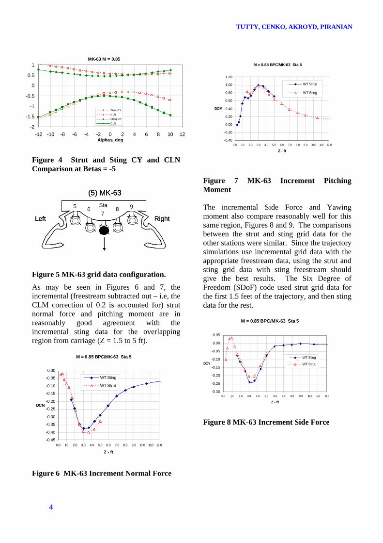
Figure 4 Strut and Sting CY and CLN Comparison at Betas = -5
4
Figure 5 MK-63 grid data configuration.
As may be seen in Figures 6 and 7, the incremental (freestream subtracted out – i.e, the CLM correction of 0.2 is accounted for) strut normal force and pitching moment are in reasonably good agreement with the incremental sting data for the overlapping region from carriage (Z = 1.5 to 5 ft).
Figure 6 MK-63 Increment Normal Force
Figure 7 MK-63 Increment Pitching Moment (5) MK-63
5 67
8 9
Left Right
Sta
(5) MK-63
5 67
8 9
Left Right
Sta The incremental Side Force and Yawing moment also compare reasonably well for this same region, Figures 8 and 9. The comparisons between the strut and sting grid data for the other stations were similar. Since the trajectory simulations use incremental grid data with the appropriate freestream data, using the strut and sting grid data with sting freestream should give the best results. The Six Degree of Freedom (SDoF) code used strut grid data for the first 1.5 feet of the trajectory, and then sting data for the rest.
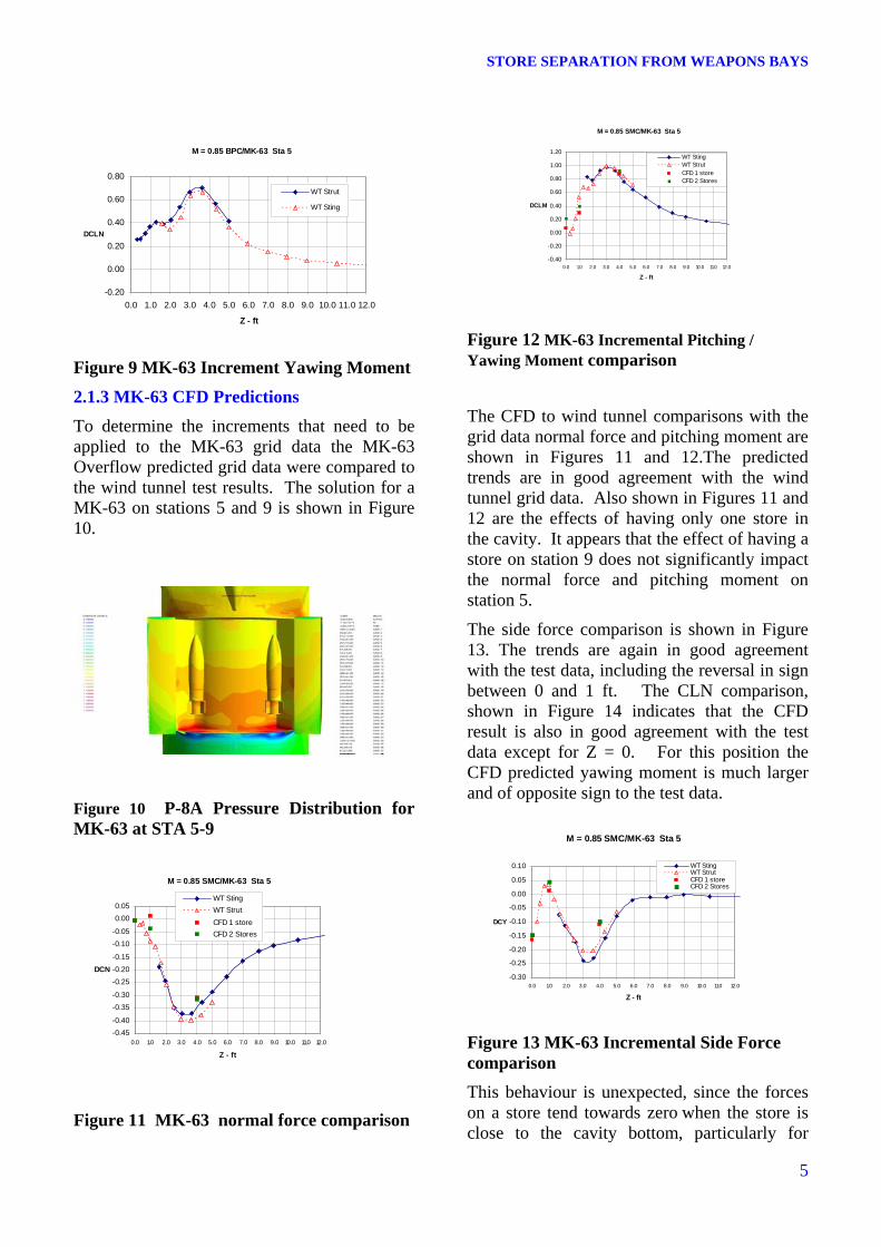
To determine the increments that need to be applied to the MK-63 grid data the MK-63 Overflow predicted grid data were compared to the wind tunnel test results. The solution for a MK-63 on stations 5 and 9 is shown in Figure 10.
Figure 10 P-8A Pressure Distribution for MK-63 at STA 5-9
Figure 11 MK-63 normal force comparison
Figure 12 MK-63 Incremental Pitching / Yawing Moment comparison
The CFD to wind tunnel comparisons with the grid data normal force and pitching moment are shown in Figures 11 and 12.The predicted trends are in good agreement with the wind tunnel grid data. Also shown in Figures 11 and 12 are the effects of having only one store in the cavity. It appears that the effect of having a store on station 9 does not significantly impact the normal force and pitching moment on station 5.
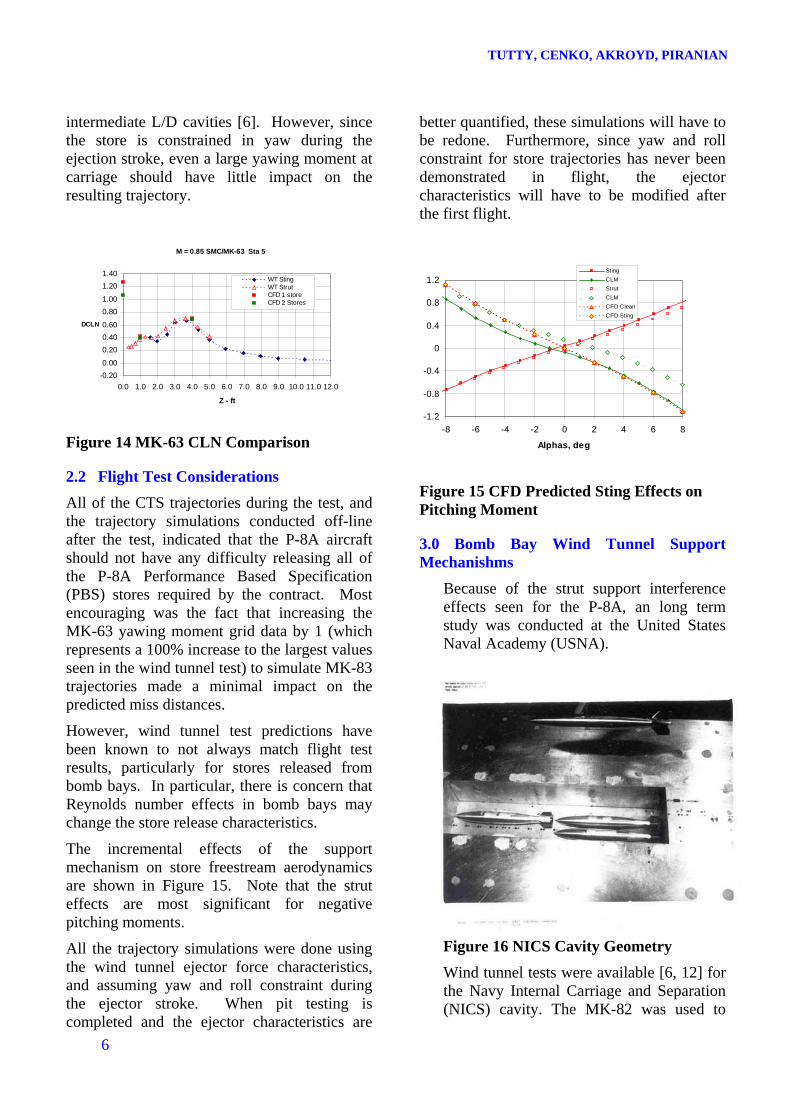
The side force comparison is shown in Figure 13. The trends are again in good agreement with the test data, including the reversal in sign between 0 and 1 ft. The CLN comparison, shown in Figure 14 indicates that the CFD result is also in good agreement with the test data except for Z = 0. For this position the CFD predicted yawing moment is much larger and of opposite sign to the test data.
This behaviour is unexpected, since the forces on a store tend towards zero when the store is close to the cavity bottom, particularly for
5
TUTTY, CENKO, AKROYD, PIRANIAN
intermediate L/D cavities [6]. However, since the store is constrained in yaw during the ejection stroke, even a large yawing moment at carriage should have little impact on the resulting trajectory.
6
Figure 14 MK-63 CLN Comparison
2.2 Flight Test Considerations
All of the CTS trajectories during the test, and the trajectory simulations conducted off-line after the test, indicated that the P-8A aircraft should not have any difficulty releasing all of the P-8A Performance Based Specification (PBS) stores required by the contract. Most encouraging was the fact that increasing the MK-63 yawing moment grid data by 1 (which represents a 100% increase to the largest values seen in the wind tunnel test) to simulate MK-83 trajectories made a minimal impact on the predicted miss distances.
However, wind tunnel test predictions have been known to not always match flight test results, particularly for stores released from bomb bays. In particular, there is concern that Reynolds number effects in bomb bays may change the store release characteristics.
The incremental effects of the support mechanism on store freestream aerodynamics are shown in Figure 15. Note that the strut effects are most significant for negative pitching moments.
All the trajectory simulations were done using the wind tunnel ejector force characteristics, and assuming yaw and roll constraint during the ejector stroke. When pit testing is completed and the ejector characteristics are
better quantified, these simulations will have to be redone. Furthermore, since yaw and roll constraint for store trajectories has never been demonstrated in flight, the ejector characteristics will have to be modified after the first flight.
Figure 15 CFD Predicted Sting Effects on Pitching Moment
3.0 Bomb Bay Wind Tunnel Support Mechanishms
Because of the strut support interference effects seen for the P-8A, an long term study was conducted at the United States Naval Academy (USNA).
Figure 16 NICS Cavity Geometry
Wind tunnel tests were available [6, 12] for the Navy Internal Carriage and Separation (NICS) cavity. The MK-82 was used to
STORE SEPARATION FROM WEAPONS BAYS
measure forces as it traversed the longitudinal axis of the cavity at several different bay depths. One such configuration is shown in Figure 16.
Figure 17 USM3D Solution for Empty NICS Cavity
This geometry of this configuration was reproduced and used to generate unstructured grids for the purposes of generating flow solutions using the USM3D code, Figure 17. In particular, comparisons of store forces and moments as it traversed the shear layer were desired. Reasonable agreement between the predictions and test data were seen [27].
As shown in Figure 18, the strut attachment hardware has a significant impact on the store aerodynamics, particularly at non zero angles of attack.
Snyder [28, 29] and Doig [30], did an extensive study using both the USNA wind tunnel and CFD to determine if strut designs could mitigate the interference effects.
Figure 18 Strut Effects on MK-83 Pressure Distributions As shown in Figure 19, the shock wave from the strut attachment interferes with the store tail, significantly changing the store pitching and yawing moments.
Figure 19 Shock Pattern on Generic Strut Store at M = 0.85
7
TUTTY, CENKO, AKROYD, PIRANIAN
4.0 Analysis of the acoustic suppression, active separation control and release of miniature munitions from RAAF F-111 aircraft
With the advent of the F-35 Lightning II JSF, P-8 Poseidon, and concepts for future Remote Piloted Aircraft / UCAVs, all designed with internal weapons carriage, forward-looking US and Five Eyes research programs focused on the understanding of the complex aerodynamics and aeroacoustics of weapons bays. The RAAF was still operating the F-111, and the Australian–US collaborators saw opportunities to use a flight-test F-111 to investigate the phenomenology of cavity flows with the Small Smart Bomb (SSB) in 2001 as reported in [13], [14] and [15]. In 2005 such work was further extended significantly with the more complex Powered Low Cost Autonomous Attack System (PLOCAAS) shapes being ejected from a Boeing pneumatic ejector rack using active separations control at [16] and [17] as shown in Figure 20.
In the collaborative program by The Technical Cooperation Program (TTCP), analysis of the release of the SSB from the F-111 Aircraft (TTCP KTa 2-22), neither the wind-tunnel, nor CFD results matched the flight-test results, [16] and [17]. Not unexpectedly, the wind tunnel results did not reflect the carriage to initial release trajectory because the aft store trajectories started some two feet (at full scale) from the carriage position, as shown in Figure
20.
Because a trajectory is largely determined by initial conditions, if these are wrong, the prediction will be in error. The forward store was tested at the end-of-stroke position; and, although those trajectories seemed to compare better, sting interference effects in the cavity might have corrupted the subsonic and transonic results. Although this collaborative program did not resolve the issue of CFD applicability to internal weapon bays, it helped determine the wind-tunnel-testing methodology for the F-35 JSF and P-8A Poseidon programs. Importantly, results from the RAAF – USAF F-111 miniature munitions program indicate that CFD can be used to account for sting-interference effects in the cavity as well as to predict the weapon-bay aerodynamics and aeroacoustics, [18].
Further, the work indicated that the lack of a priori information on sting effects could be overcome with CFD techniques; in this way, stings could be designed for minimal, or at least known, impact. For these reasons, a new collaborative program, Weapon and Cavity Aerodynamics and Aeroacoustics (KTa 2-26) was initiated in 2008, [19] and [20]. The work in this case was based on the UCAV 1303 geometry, [21]. This configuration has been widely studied, and significant experimental testing has occurred for a generic store in a rectangular weapon bay, along with complementary CFD, [18, 21].
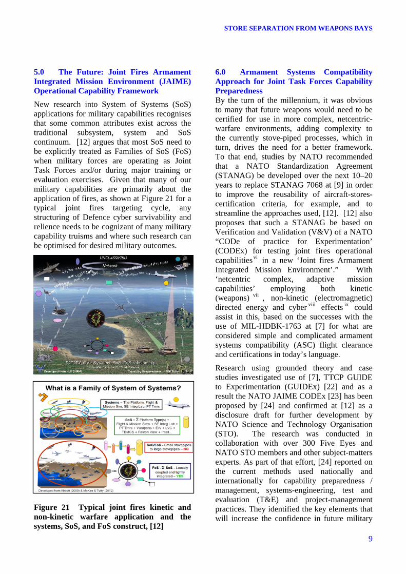
New research into System of Systems (SoS) applications for military capabilities recognises that some common attributes exist across the traditional subsystem, system and SoS continuum. [12] argues that most SoS need to be explicitly treated as Families of SoS (FoS) when military forces are operating as Joint Task Forces and/or during major training or evaluation exercises. Given that many of our military capabilities are primarily about the application of fires, as shown at Figure 21 for a typical joint fires targeting cycle, any structuring of Defence cyber survivability and relience needs to be cognizant of many military capability truisms and where such research can be optimised for desired military outcomes.
Figure 21 Typical joint fires kinetic and non-kinetic warfare application and the systems, SoS, and FoS construct, [12]
6.0 Armament Systems Compatibility Approach for Joint Task Forces Capability Preparedness By the turn of the millennium, it was obvious to many that future weapons would need to be certified for use in more complex, netcentric-warfare environments, adding complexity to the currently stove-piped processes, which in turn, drives the need for a better framework. To that end, studies by NATO recommended that a NATO Standardization Agreement (STANAG) be developed over the next 10–20 years to replace STANAG 7068 at [9] in order to improve the reusability of aircraft-stores-certification criteria, for example, and to streamline the approaches used, [12]. [12] also proposes that such a STANAG be based on Verification and Validation (V&V) of a NATO “CODe of practice for Experimentation’ (CODEx) for testing joint fires operational capabilitiesvi in a new ‘Joint fires Armament Integrated Mission Environment’.” With ‘netcentric complex, adaptive mission capabilities’ employing both kinetic (weapons) vii , non-kinetic (electromagnetic) directed energy and cyber viii effects ix could assist in this, based on the successes with the use of MIL-HDBK-1763 at [7] for what are considered simple and complicated armament systems compatibility (ASC) flight clearance and certifications in today’s language.
Research using grounded theory and case studies investigated use of [7], TTCP GUIDE to Experimentation (GUIDEx) [22] and as a result the NATO JAIME CODEx [23] has been proposed by [24] and confirmed at [12] as a disclosure draft for further development by NATO Science and Technology Organisation (STO). The research was conducted in collaboration with over 300 Five Eyes and NATO STO members and other subject-matters experts. As part of that effort, [24] reported on the current methods used nationally and internationally for capability preparedness / management, systems-engineering, test and evaluation (T&E) and project-management practices. They identified the key elements that will increase the confidence in future military
9
TUTTY, CENKO, AKROYD, PIRANIAN
capabilities being operationally suitable and effective that are evidence-based and scientifically defensible.
10
Figure 22 Capability Preparedness Levels and associated Experimentatiion, T&E and Certification Frameworkx The conceptual framework for network-enabled, force-level armament systems compatibility has been proposed to achieve balanced capability management that integrates the experimentation, systems engineering, T&E, and system-safety communities, as shown in Figures 21 to 23 throughout the life of the capability and that experimentation and testing and evaluation (ET&E) and certification is synchronized to ensure operational commanders have confidence in the capability,
at least at the Joint Task Force (JTF) level.
Figure 23 JAIME Weapon Danger Area for Yin safety and Mission Success Regions of Significant Influence (RoSI) conventions for Yang at the Mission Level for JTF FoS The key outcomes at the JTF and FoS level is a joint operational capability perspective of what is needed at the tactical and mission-levels with agreed upon understandings between all organisations. Of special interest are the users of what and [24] first called the yin - yangxi of balancing capability planning ‘inputs’ to maximise operational ‘output’ end-effects and performance.xii This yin-yang concept states:
• What may well (unintentionally) kill you and / or others (the Yang). Thoroughly understanding the RoSI that could yield adverse effects on our physical safety provides operators with a common
STORE SEPARATION FROM WEAPONS BAYS
understanding of the Weapon and EM Danger and Collateral Damage Areas/Zones for joint fires effects during operations, training and testing that is continuously updated via evidence-based data during experimentation.
• What can you confidently (intentionally) do (the Yin). More important though, is the impact any complex, adaptive system (CAS) or SoS failures within the FoS being used may have on the RoSI of the Sensor & Shooter via their C2/networked kill-chain(s) as it is equally vital to know the confidence one can have in the measures of suitability, effectiveness and performance such as PDetection and PKill for the SoS and for the expected JTF-Level FoSs during operations from what the social C2 has demonstrated in testing, training and exercise at the collective level.xiii See Figure 23 for proposed mapping of our confidence in the information and cognitive skills using JAIME.
At Movie 1 [12], the imagery graphically illustrates the application of danger areas that can be tailored to operational deliveries. It is most insightful in a paper about cyber to use an internet link xiv for this, as this is the sort of information that must be protected. Note that similar plots for showing the ROSI confidence regions would also be available for operational and planning staffs.
To effectively deal with the increasing complexity and interdependence of current and future network enabled military systems, ET&E must evolve and mature so as to detect undesirable and/or unexpected results, e.g., interdependencies of safe-separation certification with seemingly unrelated upgrades to mission-systems software. Surprises in this already complex environment will increase as the complexity of the SoS and FoS increases with national and international interoperability expectations of operational commanders and users.
To implement this strategy, a change in focus by the systems engineering, experimentation, and T&E organisations will be needed to accommodate scientifically rigorous testing, training, and experimentation that build
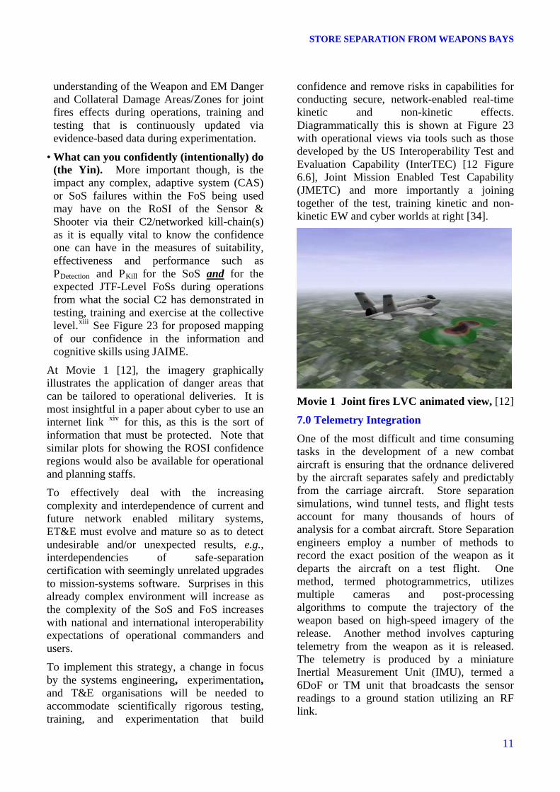
confidence and remove risks in capabilities for conducting secure, network-enabled real-time kinetic and non-kinetic effects. Diagrammatically this is shown at Figure 23 with operational views via tools such as those developed by the US Interoperability Test and Evaluation Capability (InterTEC) [12 Figure 6.6], Joint Mission Enabled Test Capability (JMETC) and more importantly a joining together of the test, training kinetic and non-kinetic EW and cyber worlds at right [34].
Movie 1 Joint fires LVC animated view, [12]
7.0 Telemetry Integration
One of the most difficult and time consuming tasks in the development of a new combat aircraft is ensuring that the ordnance delivered by the aircraft separates safely and predictably from the carriage aircraft. Store separation simulations, wind tunnel tests, and flight tests account for many thousands of hours of analysis for a combat aircraft. Store Separation engineers employ a number of methods to record the exact position of the weapon as it departs the aircraft on a test flight. One method, termed photogrammetrics, utilizes multiple cameras and post-processing algorithms to compute the trajectory of the weapon based on high-speed imagery of the release. Another method involves capturing telemetry from the weapon as it is released. The telemetry is produced by a miniature Inertial Measurement Unit (IMU), termed a 6DoF or TM unit that broadcasts the sensor readings to a ground station utilizing an RF link.
Each method has its strengths and weaknesses. The photogrammetrics is accurate in displacement, but not in attitude, particularly roll, and requires extensive preparation of the weapon and carriage aircraft, and complex post-processing of the video. The telemetry method has become more affordable, as the 6DOF units have become cheaper and smaller, and also allows the store separation engineers to track the weapon for a longer period of time than does the photogrammetrics. Typically, the certification of a new weapon on an aircraft will make use of a combination of both methods, and it is important that both methods accurately determine the true trajectory. Of course, the true trajectory is not perfectly known using either method, so a good technique is to compare the results of both methods for validation.
12
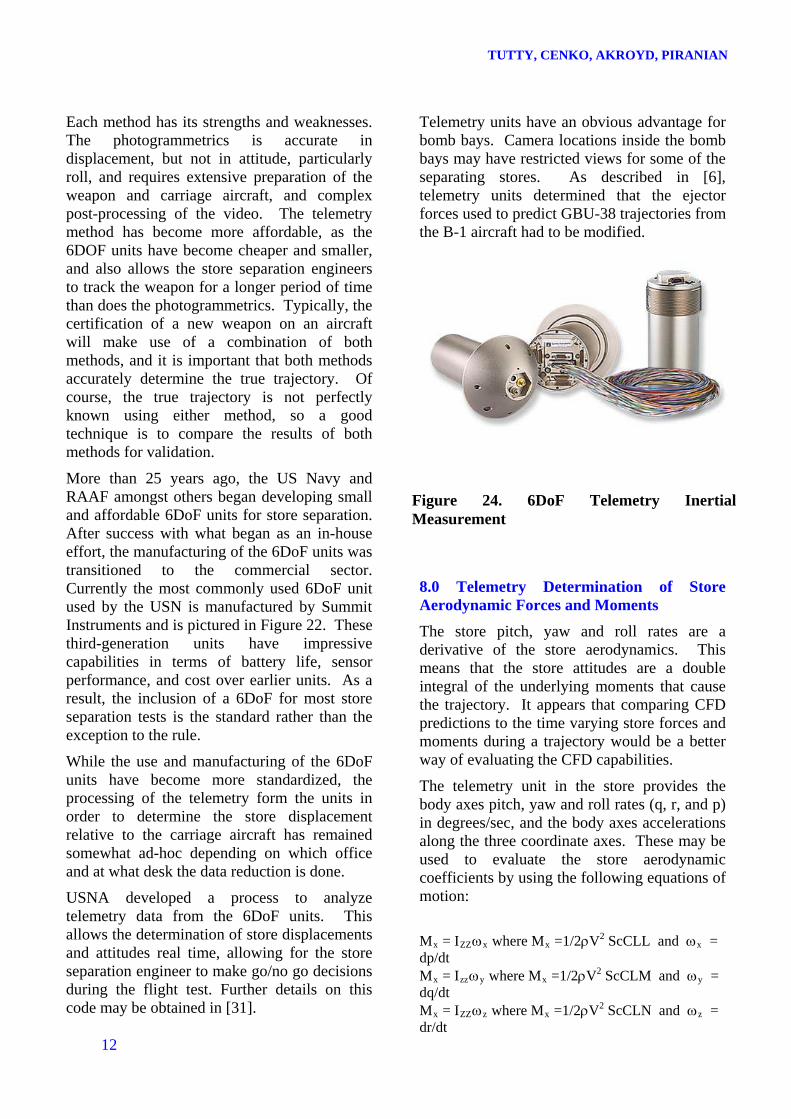
More than 25 years ago, the US Navy and RAAF amongst others began developing small and affordable 6DoF units for store separation. After success with what began as an in-house effort, the manufacturing of the 6DoF units was transitioned to the commercial sector. Currently the most commonly used 6DoF unit used by the USN is manufactured by Summit Instruments and is pictured in Figure 22. These third-generation units have impressive capabilities in terms of battery life, sensor performance, and cost over earlier units. As a result, the inclusion of a 6DoF for most store separation tests is the standard rather than the exception to the rule.
While the use and manufacturing of the 6DoF units have become more standardized, the processing of the telemetry form the units in order to determine the store displacement relative to the carriage aircraft has remained somewhat ad-hoc depending on which office and at what desk the data reduction is done.
USNA developed a process to analyze telemetry data from the 6DoF units. This allows the determination of store displacements and attitudes real time, allowing for the store separation engineer to make go/no go decisions during the flight test. Further details on this code may be obtained in [31].
Telemetry units have an obvious advantage for bomb bays. Camera locations inside the bomb bays may have restricted views for some of the separating stores. As described in [6], telemetry units determined that the ejector forces used to predict GBU-38 trajectories from the B-1 aircraft had to be modified.
Figure 24. 6DoF Telemetry Inertial Measurement
8.0 Telemetry Determination of Store Aerodynamic Forces and Moments
The store pitch, yaw and roll rates are a derivative of the store aerodynamics. This means that the store attitudes are a double integral of the underlying moments that cause the trajectory. It appears that comparing CFD predictions to the time varying store forces and moments during a trajectory would be a better way of evaluating the CFD capabilities.
The telemetry unit in the store provides the body axes pitch, yaw and roll rates (q, r, and p) in degrees/sec, and the body axes accelerations along the three coordinate axes. These may be used to evaluate the store aerodynamic coefficients by using the following equations of motion:
Mx = IZZx where Mx =1/2V2 ScCLL and x = dp/dt Mx = Izzy where Mx =1/2V2 ScCLM and y = dq/dt Mx = IZZz where Mx =1/2V2 ScCLN and z = dr/dt
STORE SEPARATION FROM WEAPONS BAYS
Note that the accelerations are also a function of the pitch, yaw and roll rates if the unit is not at the store CG as described in detail in [31] (usually, it's in the nose or tail).
Flight test telemetry data were available from [32] for the MK-84 store separating from the F/A-18C aircraft at two separate Mach numbers. As may be seen in Figure 25 and 26, the MK-84 store pitching and yawing moments were obtained from the telemetry data by using the equations shown above. Since the telemetry data is at fixed time steps, differentiation leads to an oscillatory behavior. There is a substantial difference in the yawing moment data at M = 0.90 and M = 0.93. Obviously, a smoothing function needs to be applied to the raw telemetry data.
Figure 25 MK-84 Pitching Moment
Figure 26 MK84 Yawing Moment
The sudden change in pitching moment seen during the first 50ms is due to an offset between the store CG and the ejector feet, and would be ignored in comparing the pitching moment coefficient predictions.
-2.8
-2.4
-2
-1.6
-1.2
-0.8
-0.4
0
0.4
0.8
1.2
1.6
2
0 0.05 0.1 0.15 0.2 0.25 0.3 0.35 0.4
time, sec
MK-84/Litening M = 0.90 550 KCAS
CLN
CLN Pred
Figure 27 MK-84 Yawing Moment MK-84/Litening M = 0.90/0.93
-4
-3
-2
-1
0
1
2
0 0.05 0.1 0.15 0.2 0.25 0.3 0.35 0.4
time, sec
CLM
M = 0.93
M = 0.90
A comparison of the pre-flight predicted yawing moment with the telemetry data averaged over three time steps is shown in Figure 24. The reason the telemetry data indicates a yawing moment of zero for the first 20ms may be attributed to friction between the ejector pistons and the store.
MK-84/Litening M = 0.90/93
-2.8
-2.4
-2
-1.6
-1.2
-0.8
-0.4
0
0.4
0.8
1.2
1.6
2
0 0.05 0.1 0.15 0.2 0.25 0.3 0.35 0.4
time, sec
CLN
M = 0.93
M = 0.90
Figure 28 Yawing Moment During F-35 JSF Ejection As seen in Figure 28 this approach was used for the JSF program as described in [33]. 9.0 Conclusions and Recommendations Over the past three decades, collaboration between the Five Eyes in the area of aircraft
13
TUTTY, CENKO, AKROYD, PIRANIAN
stores certification and separation in particular has considerably improved the capabilities of each nation. These joint efforts have established the credibility of new tools, eliminated duplication, and provided significant cost and time savings.
These collaborative efforts were the result of predominantly Five Eyes and NATO, ASCC and TTCP international agreements and specialist conferences (AIAA, ICAS, ITEA), as well as agreements between individuals to do interesting work that would complement their respective agencies’ priorities. Future joint task forces using families of systems of systems will require even more collaborative and cooperative systems for aircraft-stores configurations to be part of a greater framework that has network-enabled armament systems compatibility across the systems of systems and are operationally suitable, effective and prepared.
CFD has become an increasingly accepted tool in the aircraft stores separation and certification process. The paper discussed how there is the possibility of greatly reducing the size and scope of the store separation flight test programs. CFD can be used early in the design program to make the aircraft “store friendly”. CFD can also help design the store attachment hardware and to determine the critical test points to be covered in the wind tunnel test program. Telemetry can be used to back out and correct the CFD and wind tunnel predictions.
14
MIL-HDBK-1763 at [7] has been critical to this revolution in air armament affairs until now, to which ACFD has been a common Five Eyes initiative. To address the network enabling of joint fires operational capabilities, the Five Eyes and NATO need to urgently develop and implement use of a replacement based on the research underpinning the proposed JAIME CODEx to ensure that armament system compatibility is established and maintained for increasing the confidence of commanders and operational users in what levels of interoperability and capability preparedness are demonstrated and are scientifically based. The tools developed in use of CFD in the aircraft
stores separation and certification area are long overdue for use in other domains such as non-kinetic electromagnetic compatibility, directed energy and cyber operations to achieve this.
References
1. Taverna, F. P., Cenko, A., Navy Integrated T&E Approach to Store Separation, Paper 13, RTO Symposium on Aircraft Weapon System Compatibility and Integration, Chester, UK, October 1998.
2. Sisco, B., and Cenko, A., SPLITFLOW Prediction of MK-83 Trajectories from the CF-18 Aircraft, AIAA Paper 2001-2430, June, 2001.
3. Walsh, J., and Cenko, A., USM3D Prediction of MK-83 Trajectories from the CF-18 Aircraft, AIAA Paper 2001-2430, June, 2001.
4. Ryckebusch, C., Niewoehner. R. and Cenko A., Sisco, B. and Walsh, J., Evaluation of the Capabilities of CFD to Predict Store Trajectories from Attack Aircraft , AIAA Paper 2002-0279, January, 2002.
5. Ray, E. S.,CFD Method for Separation of SLAM-ER from S-3B and P-3C, AIAA 2003-4226.
6. Cenko, A., et. al., Influence Function Method Applications to Cavity Flowfield Predictions, AIAA Paper 89-0477, Jan. 1989.
7. MIL-HDBK-1763, Aircraft Stores Compatibility: Systems Engineering Data Requirements and Test Procedures, US DoD Handbook, dated 15 June 1998, USA
8. MIL-HDBK-244A, Guide to Aircraft/Stores Compatibility, US Department of Defense, USA, dated 6 April 1990.
9. STANAG 7068, NATO Standardization Agreement Aircraft/Stores Certification Procedures, 12 July 2011, Edition 2, NATO Military Agency for Standardization, 1110 Brussels, Belgium
10. NATO STO AGARDOgraph 300 Vol 29, Aircraft/Stores Compatibility, Integration and Separation Testing, Brussels, Belgium, 2014
STORE SEPARATION FROM WEAPONS BAYS
11. Tutty, M.G., Akroyd, G., and Cenko, A., ACFD Challenge II revisited after 15 Years, 8th ANKARA International Aerospace Conference, 10-12 September 2015 - METU, Ankara TURKEY
12. Tutty, M.G., The profession of arms in the Information Age: operational joint fires capability preparedness in a small-world, Thesis submitted for the Degree of Doctor of Philosophy, University of South Australia, 1 July 2015 with Examiners Comments, 1 January 2016 [Online, posted March 2016]. See www.maltutty.com / Contents
13. Balogh, N., and Lopez, R., US / Australian F-111G Miniature Munitions Flight Test Program, 10th ASC ITEA, Ft Walton Beach, FL, 2003
14. Leugers, J., et al, Flight Test Demonstration of Miniature Munitions Release from Internal Weapons Bay – Final Test Report, AFRL-MN-EG-TR-2002-7011, January 2002
15. Baskaran, V., Cenko, A., Foster, G.W., Grove, J., Johnson, R., Lee, J., Orchard, D., and Tang, F.C., Analysis of the release of the SSB from the F-111 aircraft. KTA 2-22, TTCP, 2007.
16. Morgret, C.H., Predicted Separation Characteristics of the Powered Low-Cost Autonomous Attack System (PLOCAAS) from the F-111 Aircraft Based on Wind Tunnel Measurements. Arnold Engineering Development Center Report (Draft), 2003.
17. Blyth, R.H., Trajectory predictions of the Powered Low-cost Autonomous Attack System (PLOCAAS) Tandem Park released from the weapon bay of the F-111G aircraft. Defence Science and Technology Organisation (Australia), 2003.
18. Cenko, A., Lee, J., Getson, E., Hallberg, E., Jolly, B., and Sickles, W., IHAAA applications to reducing store separation flight testing, AIAA-2007-165, 20073.
19. Chaplin, R., and Birch, T., Aero-acoustics and store release from the weapons bay of a generic UCAV. AIAA-2012-3338, 2012.
20. Wong, M., McKenzie, G.J., Ol, M.V., Pettersen, K., and Zhang, S., Joint TTCP CFD studies into the 1303 UCAV
performance: First year results. 24th Applied Aerodynamics Conference, San Francisco, US, AIAA-2006-2984
21. Aircraft Research Association., Tests conducted in the ARA 2.74 m x 2.44 m Transonic Wind Tunnel on the release of a generic MK-82/GBU-30 JDAM store model from a generic UCAV model using the two sting rig. M 399/2, 2002.
22. GUIDEx, TTCP Guide for Understanding and Implementing Defense Experimentation (GUIDEx), The Technical Cooperation Program, 2006, [Online, accessed 15 July 2007]. URL: http://www.dtic.mil/ttcp/guidex.htm
23. JAIME CODEx, Armament Systems Compatibility: Joint fires Armament Integrated Mission Environment, Code of Practice for Test, Experimentation and Certification – JAIME CODEx and The Tests, Disclosure Draft V2.0, 2014, [Posted online October 2014] www.maltutty.com
24. McKee. S., and Tutty, M.G., Doing more of the right high end effects-based things without more - from basics to families of system of systems capabilities. ITEA Journal 2012, Vol 31, No. 33, September, 2012 JITE-33-03-05 pp 203 – 243 [Online, accessed May 2013] www.maltutty.com
25. US Joint Forces Publication JP 3-09, Joint Fire Support, 13 Nov 2006
26. US Joint Forces Publication FM 3-09.32, JFire - Multi-service Tactics, Techniques and Procedures for the Joint Application of Firepower, December 2010
27. Finney, L., An Investigation of Cavity Flow Effects on a Store In the Vicinity of the Shear Layer, ITEA Aircraft Stores Compatibility Symposium, April 2010.
28. Snyder, M., et al., “Strut Effects on Store Freestream Aerodynamics,” AIAA Paper 2011-3159, June 2011.
29. Snyder, M., et al., US Naval Academy Store Separation Simulation Program, AIAA Paper 2011-7042, Sept. 2011.
30. Doig, G., et al., Aspects of Sting Interference for Transonic Store Release Wind Tunnel Testing, AIAA Paper 2013-0642, Jan. 2013.
31. Hallberg, E., and Godigsen, W., MATLAB Based Telemetry Integration Utility for Store Separation Analysis, ITEA International Symposium, November, 2007.
32. Cenko, A., IHAAA Applications to Reducing Store Separation Flight Testing, AIAA paper 2007-1653, Feb. 2007.
33. Hetereed, C., F-35 Joint Strike Fighter: Store Separation Flight Test and Analysis, 2013 MSC Software Users Conference, May 7-8, 2013, Irvine, CA
34. Tutty, M.G., McKee, S.V. and Sitnikova, E., 2016, Joint fires superiority: kinetic and non-kinetic electronic and cyber warfare, SETE Symposium 2016, Melbourne, Victoria, Australia, 18 – 19 May 2016 [Posted online 10 May 2016] www.maltutty.com / Contents
The authors confirm that they, and/or their company or organization, hold copyright on all of the original material included in this paper. The authors also confirm that they have obtained permission, from the copyright holder of any third party material included in this paper, to publish it as part of their paper. The authors confirm that they give permission, or have obtained permission from the copyright holder of this paper, for the publication and distribution of this paper as part of the ICAS proceedings or as individual off-prints from the proceedings.
i An aircraft stores configuration refers to an aerospace platform, incorporating a stores management system(s), combined with specific suspension equipment and aircraft store(s) loaded on the aircraft in a specific pattern. An aircraft stores configuration also includes any downloads from that specific pattern resulting from the release of the store(s) in an authorised employment or jettison sequence(s) All definitions are from [7], unless noted otherwise.
ii Those personnel who are uniformed members of a professional military force. This includes those personnel who are professionally involved in live experimentation, trials and employment of arms: be they kinetic, non-kinetic or cyber-based in so far as they are used to destroy or neutralise threats.
iii An integrated composite of people, products and processes that provide a capability to satisfy a stated need or objective.
iv A SoS results when independent and useful systems are integrated into a larger system that delivers unique capabilities, The distinguishing feature of a SoS over a large monolithic system is that a SoS comes into being from a series of acquisition actions and typically has no one single operations, technical, logistics or management entity.
v Those "fires produced during the employment of forces from two or more components in coordinated action to produce desired effects in support of a common objective." “Fires” are "the use of weapon systems to create a specific lethal
or nonlethal effect on a target. All fires are normally synchronized and integrated to achieve synergistic results. Fires can be delivered by air, land, maritime, or special forces." It’s the basis of terms like “Fire Control System” etc.
vi See [12] for US Joint Forces Publications [25] and [26] and US Range Commander Council 321 2007 details.
vii Kinetic conventional weapons effects - developing weapon force applications options over the next five to ten years for future Joint Fires training/testing and tailored operational effects for:
• All weather, day/night, long range, hypersonic and loitering, autonomous air, sea and land weapons.
• Network-Enabled Weapons & Data Link Architectures.
viii Non-kinetic electromagnetic effects - developing Electromagnetic force application and protection options over the next one to two decades for future Joint Fires training/testing and tailored operational effects for:
• Electronic Warfare - Navwar / GPS Denial / EMS Denial / Force Protection ECM / • Passive EW Self Protection measures will
remain but active Directed RF/IR Countermeasures will predominate.
• Directed-energy as the ultimate non-kinetic effect and to exploit EM vulnerabilities.
• Spectrum Management changes & avoiding ‘spectricide’ – issues include mobile phones, new bands, secure telemetry, complex,
adaptive and multipath range networks. • Cyber / Information Operations.
ix See also [12] for excellent discussions from Bird (2014), Applegate (2013), Stallard (2009) and Sanders (2014) on the Australian perspective for the implications of networked weapons and aircraft ‘generations’, ‘kinetic cyber’ respectively.
x The following definitions are proposed by [12] for categorisation of systems, SoS & FoS in joint fires operations: Ops Category A – mission and safety
critical operations. Ops Category B – mission critical – safety
affected operations. Ops Category C – mission affected /
advisory – ‘non-safety critical’ operations. Such a taxonomy aligns with the systems, SoS and FoS views and the three V&V implications levels as proposed at [12 Table 6.1]). This is vital to delineate those systems, SoS and FoS that are OPS CAT A and safety critical, complex and adaptive in nature versus OPS CAT C engineered systems.
xi In Chinese philosophy the concept literally means "shadow and light". This aspect of weapons performance (the yang) and safety templates (the yin) has not been sufficiently explored in the field to date.
xii Both have to be addressed to be sufficient, while noting that such balance has not been analytically possible or undertaken to date as far as the author and the SMEs involved in the research are aware.
xiii Note that the RoSI is predominantly ‘Threat or Target-centric.’ Which means that systems to do RoSIs must be able to be made both Shooter and Threat/Target centric.
xiv [12 Movie 1] has a hypertext link to http://www.maltutty.com/content/joint%20fires%20LVC%20view.mpg embedded, which will play by ‘CNTRL CLICK’, iff your computer viewing this document is connected to the Internet.