82
Storm Reconstruction: Rebuild Smart Reduce Outages, Save Lives, Protect Property
Storm Reconstruction: Rebuild Smart
Reduce Outages, Save Lives, Protect Property

Published by NEMA Communications
The National Electrical Manufacturers Association 1300 North 17th Street, Suite 1752, Rosslyn, VA 22209703.841.3200 • www.NEMA.org/Storm-Reconstruction
© Copyright 2013 by NEMA All rights reserved including translation into other languages, reserved under the Universal Copyright Convention, the Berne Convention for the Protection of Literary and Artistic Works, and the International and Pan American Copyright Conventions.

3
CONTENTS
Overview
Smart Grid Solutions
Smart Meters and Disaster Recovery ............................................................................................................13
Smart Meters Can Reduce Power Outages and Restoration Time ...............................................................15
Preparing and Restoring Power Grids Using Smart Grid Technologies .........................................................18
Severe Weather and Distribution Grid Automation ........................................................................................21
Integrating a Fault Location, Isolation, and Service Restoration System into an Outage Management System ........................................................24
Improving Grid Resilience through Cybersecurity ..........................................................................................28
Microgrids, Energy Storage, and Decentralized Generation
The Power of Microgrids ................................................................................................................................31
Energy Reliability with Microgrids ..................................................................................................................33
The Role of Energy Storage in Disaster Recovery and Prevention ...............................................................37
Integrating Energy Storage into the Distribution System ...............................................................................40
Combined Heat and Power and Grid Resiliency ............................................................................................42
Key to Staying Connected is Disconnecting ..................................................................................................45

4
Backup Generation
Backup Power Systems .................................................................................................................................47
Incorporating Generators and System Upgrades for Storm Preparation .......................................................51
Wiring, Cabling, and Components
Upgraded Wire and Cable Systems Can Accelerate Storm Recovery ..........................................................55
Submersible Transformers and Switches, Advanced Monitoring and Control ...............................................59
Submersible Automated Switchgear ..............................................................................................................62
Replacing and Relocating Equipment
Emergency Preparedness and the Importance of Equipment Repositioning ................................................65
Replacing or Upgrading Water-Damaged Electrical Equipment ....................................................................69
Disaster Recovery
Disaster Recover Planning ............................................................................................................................73
Prioritizing Necessary Upgrades: The Graceful Degradation Principle .........................................................77

5
OverviewSevere weather, coupled with an aging and overstressed electrical infrastructure, is having a dramatic impact on the U.S. population.
In late 2012, Superstorm Sandy’s devastation left 132 people dead; more than 8 million people in 16 states lost power; subway tunnels were inundated with water; 305,000 homes in New York City and 72,000 homes and businesses in New Jersey were damaged or destroyed; sewage plants were crippled, causing hundreds of millions of gallons of sewage to flow into waterways; and four New York City hospitals shut their doors.
Rebuilding after any major storm is a formidable challenge. The core principal of any major reconstruction effort should be to “rebuild smart,” ensuring that reconstruction funds maximize the deployment of technologies to mitigate future power outages, save lives, and protect property.
Resilient and reliable power is critical for first responders, communications, healthcare, transportation, financial systems, water and wastewater treatment, emergency food and shelter, and other vital services. When smart technologies are in place, power outages are avoided and lives, homes, and businesses are protected.
Good examples are the deployment of microgrids, energy storage, and cogeneration. As reported in the MIT Technology Review:
■■ Local power generation with microgrids showed the benefits of reliability during Hurricane Sandy.
■■ The Food and Drug Administration’s White Oak research facility in Maryland switched over to its onsite natural gas turbines and engines to power all the buildings on its campus for two and a half days.
■■ Princeton was able to switch off the grid and power part of the campus with about 11 megawatts of local generation.
■■ Similarly, a cogeneration plant at New York University was able to provide heat and power to part of the campus.
■■ A 40MW combined heat and power plant in the Bronx was able to provide electricity and heat to a large housing complex.1
The 400-plus member companies of the National Electrical Manufacturers Association (NEMA) and its staff of experienced engineers and electroindustry experts—spanning more than 50 industry sectors—stand ready to assist industry and government officials when rebuilding after a disaster.
______________________________1 Advanced Metering Infrastructure (AMI) Evaluation Final Report Completed for Commonwealth Edison Company (ComEd),
Black & Veatch, July 2011
Overview

6
The remaining pages of this overview section describe key technologies highlighted in this document, noting their ability to contribute to a more resilient electric grid.
Smart Grid Solutions Rebuilding the electric power system should incorporate the use of Smart Grid solutions—information and communications technologies, such as smart meters and high-tech sensors, to isolate problems and bypass them automatically. These technologies provide resilience—quick recovery from extreme weather and other outages.
In much the same way as new information and communications technologies are reshaping how we work, learn, and stay in touch with one another, these same technologies are being applied to the electric grid, giving utilities new ways to manage the flow of power and to expedite restoration efforts.
By integrating information and communications technologies into the electric grid, utilities can not only minimize the extent of an outage, but also immediately identify customers who are impacted, shunt electricity around downed power lines to increase public safety, and enable faster restoration of services.
For example, when disturbances are detected in the power flow, modern circuit breakers can automatically open or close to help isolate a fault. Much like a motorist using his GPS to find an alternate route around an accident, this equipment can automatically re-route power around the problem area so that electricity continues to flow to other customers. Smart Grid solutions also enable utilities to protect the electric grid from cyberattack.
Smart Grid issues and options discussed in this guide:
■■ Smart meters have two main components: an electronic meter that measures energy information accurately and a communication module that transmits and receives data.
■■ The primary drivers for deployment of smart meters have been cost reduction and energy savings. Less prominent, but just as important, is the role of smart meters in disaster recovery situations because of their capabilities as smart sensors.
■■ Smart meter communications provide information on where outages have occurred, allow power to be cut to certain areas to minimize the risk of fire or injury, and enable demand response to manage customer consumption of electricity in response to a stressed distribution system.
■■ Another benefit of smart meters is verification of power restoration, which is accomplished when a meter reports in after being reenergized. This provides automated and positive verification that all customers have been restored, there are no nested (isolated) outages, and associated trouble orders are closed before restoration crews leave the areas.
■■ Distribution automation systems can reduce outage times by automatically detecting a fault, isolating the faulted section from the grid, and restoring service to the unfaulted sections. Integrated distribution management systems, together with smart meters, provide control room operators with real-time information on outages rather than waiting for customers to call.

7
■■ If most of a grid is still functional, a fault location, isolation, and service restoration (FSLIR) system, integrated into an outage management system can restore power to unfaulted portions line in seconds.
■■ FLISR systems in tandem with advanced distribution automation enable efficient restoration of the grid.
■■ Modern reclosers have shortened dead time during auto reclosing, include voltage and current sensors, and can be equipped with intelligent controllers.
■■ Another component of Smart Grid is flood resistant fiber optics, which can be used to measure current.
Microgrids, Energy Storage, and Other Distributed Generation systems
When power interruptions occur, microgrids, energy storage, and other distributed (i.e., decentralized) generation systems can ensure continued operation of critical facilities.
A microgrid, sometimes referred to as an electrical island, is a localized grouping of electricity generation, energy storage, and electrical loads. Where a microgrid exists, loads are typically also connected to a traditional centralized grid. When the microgrid senses an outage, it disconnects from the central grid and uses its own generation and storage capabilities to serve the local electrical load.
In critical situations microgrids can direct power to high priorities such as first responders, critical care facilities, and hospitals.
Microgrid generation resources can include natural gas, wind, solar panels, diesel or other energy sources. A microgrid’s multiple generation sources and ability to isolate itself from the larger network during an outage on the central grid ensures highly reliable power.
The effectiveness of microgrids is further enhanced through energy storage. Storage systems not only provide backup power while the microgrid’s generation sources are coming online, they can also be used to regulate the quality of the power and protect sensitive systems like hospital equipment that may be vulnerable to power surges during restoration efforts.
Microgrids offer additional advantages. Surplus power from microgrids can be sold to the central grid or stored for later use. In combination with energy storage and energy management systems, microgrids can also provide ancillary services to the broader electric grid such as voltage and frequency regulation. Microgrids also reduce dependence on long distance transmission lines—reducing transmission energy losses.
Also of increasing importance, microgrids can mitigate the effects of cyberattacks by segmenting the grid.

8
Microgrid, energy storage, and distributed/decentralized energy systems discussed in this guide:
■■ Microgrids are essentially miniature versions of the electric grid that include localized generation and storage. Localized and increasingly clean generation allows microgrids to provide power to campuses and small communities independent of a macrogrid. These stability islands can keep whole communities of rate payers warm, fed, and safe and allow first responders to start their work sooner.
■■ A microgrid can coordinate a network of backup generators ensuring the optimum use of fuel.
■■ Microgrids can tie in alternative energy sources such as wind and solar, gas turbines providing combined heat and power (CHP), and energy storage systems. They also have the ability to automatically decouple from the grid and go into island mode.
■■ A successful microgrid must have intelligent methods to manage and control customers’ electrical loads.
■■ University campuses, military bases and other federal facilities, hospitals, large research and data centers, industrial parks, and waste water treatment plants are good candidates for microgrids because they typically have a common mission and are managed by the same organization
■■ Microgrids are also appropriate for a densely populated urban area, such as Manhattan, where concentration of energy use is high and significant scale justifies connecting multiple buildings as part of a microgrid network.
■■ New energy storage system designs offer safer and longer operational lifespans, as well as allow customers to install large battery systems that provide emergency power to critical functions when the grid fails. Equally important is their capacity to produce revenue and reduce costs during normal operation.
■■ Advanced technology battery systems have already proven their ability to nearly double the efficiency of the diesel generators they support.
■■ Energy storage systems can also reduce thermal strain on the grid during peak load periods and provide a reliable backup power supply in the event of a major storm, other natural disaster, or cyberattack.
■■ Emergency relief centers can be sustained during outages by incorporated advanced energy storage systems.
■■ A fleet of large-capacity energy storage units distributed throughout the grid can support hundreds of homes, small businesses, and critical infrastructure during an outage. When combined with a community’s renewable generation resources, the resultant microgrid is capable of operating for many hours or even days.

9
■■ For most facilities with the need to maintain power throughout every type of grid disruption, combined heat and power (CHP), also commonly referred to as cogeneration, should be considered. CHP captures waste heat from the generation of electricity—typically by natural gas turbines—to provide heat and hot water, steam for an industrial process, or cooling for a data center. CHP is more energy efficient than producing electricity and heat separately.
■■ The integration of advanced battery storage systems with CHP has the potential to create a safe, resilient, and efficient energy campus microgrid.
Backup Generation
Onsite backup power provides a reliable and cost-effective way to mitigate the risks to lives, property and businesses from power outages. For many facilities, such as assisted living facilities and nursing homes, there is a life safety aspect to consider. Other facilities, such as cell tower sites, emergency call centers, and gas stations, have far-reaching social impact and availability is critical.
For businesses with highly sensitive loads such as data centers and financial institutions, the risk of economic losses from downtime is high. One way to mitigate these various risks is onsite backup power equipment.
Traditionally, diesel and natural gas generators are used to provide long-term backup generation. When combined with energy storage, continuous power can be provided without disrupting even the most sensitive medical and electronic equipment.
Backup generation issues and options discussed in this guide:
■■ Onsite electrical power generating systems are readily available in a wide variety of designs for specific uses and customer applications.
■■ Remote monitoring and control systems that allow an operator to check the system status and operate the system remotely are becoming more commonplace.
■■ It is important to consult code requirements for emergency power.
■■ The overall cost and ease of installing backup generation depends upon the layout and physical location of all elements of the system—generator set, fuel tanks, ventilation ducts, accessories, etc.
■■ Backup systems need to be designed for protection from flooding, fire, icing, wind, and snow.
■■ Emissions and Environmental Protection Agency requirements should be taken into consideration at the early stages of backup power decision making.
■■ Lack of adherence to a preventative maintenance schedule is one of the leading causes of failure of a backup power system.
■■ It is important to work with a power generation firm that can help assess backup power needs to ensure selection of the optimal backup power system.
■■ It is prudent to have sufficient emergency generator fuel on hand to allow at least 48 hours of operation or as required by code.

10
■■ Florida requires some gas stations to have generators to run pumps in the event motorists need to fuel up for an evacuation.
■■ It is essential that generators are connected properly; improper connections can result in electrocution or fires.
Wiring, Cabling, and Components
For critical equipment, cabling should be used that is resistant to long-term submersion in water, as well as oil and other pollutants potentially present in flood waters that may have an effect on less robust insulation materials.
In addition, there are classes of transformers, switches, and enclosures that are designed to be submersible. Initial equipment installation can be more expensive than non-submersible equipment, but can pay for itself in subway systems and substation environments that are susceptibleto flooding.
Water resistant wiring, cabling, and components issues and options discussed in this guide:
■■ For cities where much of the power infrastructure is below street level, install submersible transformers and switches.
■■ Deploy switchgear specially designed for subsurface application in vaults resistant to flood waters containing contaminants.
■■ Medium-voltage (MV) switchgear, especially for electrical substations, is available in gas-insulated form, which means that all electrical conductors and vacuum interrupters are protected from the environment. This type of containment makes MV switchgear conductors resistant to water contamination.
■■ In the rebuilding effort following a major storm, the question of how to rebuild existing circuits and which wiring and cables to install are key considerations, arguably the most important considerations from a cost perspective.
■■ Installing wire and cable that have specific performance characteristics (e.g. water resistant or ruggedized) as well as utilizing installation methods that reduce exposure to the elements (e.g. relocation, undergrounding, and redundancy) can improve an electrical system’s protection from storm damage.
■■ Damage to cables occurs because the flooded wiring is not designed to withstand submersion in water. The answer is to use robust wet-rated cables indoors in any areas that can be exposed to flood waters.
■■ When upgrading line capacity, storm-hardening existing lines, or installing new lines, installers can benefit from the use of underground high voltage cable systems that have a history of high reliability and are largely immune to high winds and flooding.
■■ Covered aerial medium-voltage systems can greatly improve the reliability and reduce the vulnerability of overhead distribution during major weather events.
■■ Self-healing cables ensure that minor insulation damage to underground 600V cables is limited. Channels between insulation layers hold a sealant that flows into insulation breaks and seals them permanently, preventing the corrosion failures that typically occur with exposure to moisture.
11
■■ Using wet-rated products in industrial and commercial applications, especially in critical circuits, can reduce the time and cost of restoring operations after flooding.
■■ Residential wiring in basements and other vulnerable areas can be made more flood-resistant by substituting a wet-rated product for the commonly used dry-rated one. This may allow power to be restored to residences more quickly without extensive wiring replacement.
Relocation or Repositioning of Equipment
Another smart use of rebuilding funds is relocating or repositioning of equipment or power lines. In light of the devastation caused by recent floods and storms, it is time to evaluate the location of critical infrastructure and identify situations where investing money today will protect vital equipment from future storms.
Relocation and repositioning issues and options discussed in this guide:
■■ The National Electrical Code® requires risk assessments for mission critical facilities. An important part of the risk assessment is evaluating the positioning of critical equipment. For instance, are backup generators elevated above ground so that they are safe from water in the event of flooding? Are the pumps supplying fuel to the generators also located above ground so that in the event of flooding it’s still possible to fuel the generators?
■■ A simple cost-effective idea is to elevate standby generators at sites prone to flooding to higher elevations. This concept is particularly important when installing new equipment and substations.
Disaster Recovery Planning
After a disaster, power should be restored to the most critical services first. In addition, planning efforts should carefully consider safety issues that can emerge when recovering from flooding.
Disaster recovery planning issues and options discussed in this guide:
■■ Electrical equipment that has been submerged should never be re-energized without being thoroughly inspected. Equipment that has been submerged is likely to have debris disrupting its operation and damaged electrical insulation that can cause fires and shock hazards when the devices have been energized.
■■ All manufacturers of circuit breakers require that they be replaced after being submerged.
■■ Perform a pre-crisis risk mitigation audit and identify ways of minimizing vulnerability in the event of a disaster.
■■ Train employees so they know what to do. Make sure they understand that flood waters conduct electricity.
■■ Obtain a qualified first-response service provider with experienced personnel for the equipment at your facility.
12
■■ Identify sources of equipment repair and replacement.
■■ Plan for the failure of communication systems.
■■ Install premises-wide surge protection to protect sensitive loads from pulses during power restoration.
■■ Install advanced arc-fault and ground-fault protection to remove power from storm damaged circuits so that power restoration does not cause fires and electrocutions.
■■ There are benefits to upgrading rather than replacing flood damaged components including availability, new technology, and long-term reliability.

13
Smart Meters and Disaster RecoveryOver the last decade, smart meter technology has been installed in millions of residential and commercial users in the United States. Indeed, the U.S. is ahead of much of the rest of the world as utilities install smart meters across their service areas. For much of the industry, the primary business drivers for deployment have been cost reduction and energy savings. Cost reduction is relatively easy to justify because smart meters can reduce or eliminate the cost of physically visiting meters to collect readings for billing purposes. Advanced meters also include remote control switches to disconnect power as well as measure time-of-use, again without the need for physical visits. For energy savings, smart meters also provide a way for utilities to offer services to reduce consumption by managing individual appliances in return for a reduced rate. These technologies are proven, mature, and are widely deployed.
Less prominent, but just as important, is the role of smart meters in disaster recovery situations. It’s important to remember that smart meters are smart sensors. In addition to measuring energy usage for billing purposes, these sensors can provide valuable functions during disasters and during recovery. The following paragraphs outline a weather disaster scenario and the role that smart meters play in managing the situation. All of the capabilities described here are available and shipping with current smart meter technology.
Example Scenario
As the storm rolls in, utility managers begin preparing. They start by comparing real and reactive power measurements on commercial and industrial (C&I) meters to see which commercial customers are still running large inductive loads. These loads indicate the activity of large electric motors and indicate which factories are running or shutting down. Smart meters provide these measurements over short periods, allowing utility managers to see which motor loads are shed prior to a storm. Information on factory shutdowns can be forwarded to public disaster coordinators. Next, the utility managers verify that known vacant buildings and houses have been disconnected from the grid by sending messages to smart meters. This action helps to prevent fires in case of major structural damage that would otherwise go unreported. If circuits are still active, disconnect commands can be sent to properly equipped smart meters and executed within seconds.
As the storm blows through, inevitable power outages begin to occur as power assets are disrupted. In some cases, distribution feeders are cut and power is restored automatically through another path. In other cases, however, distribution feeders are completely disrupted and power is lost. In still other locations, individual drops are cut, or transformers or other assets are damaged. These disruptions are extremely difficult to diagnose from a utility standpoint, because most utilities have little or no instrumentation on them. Similar to the fog of war, utility operators are overwhelmed by waves of information from telephone calls, first responders, and their own crews. It’s difficult to prioritize the work or to even know what kind of crew to dispatch to a particular location.
Smart G
rid Solutions

14
Luckily, smart meters can help. Smart meters use capacitors or batteries to store sufficient energy to send out a “dying gasp” message in the event of power loss. As this information is collected and analyzed a clear picture of the various outages begins to emerge. If a large group of meters goes out at the same time on the same distribution feeder, it’s likely that the feeder is damaged. Likewise, if all meters on a particular transformer or particular street report outages, the problem can be isolated to that location. Smart meters can even be used to detect disruptions to individual drop wires if neighbors still have power. More importantly, these disruptions can be located, analyzed, and acted on long before consumers even begin to report in with phone calls. This enables the utility and emergency coordinators to not only know where power is out, but predict when it will be restored down to individual addresses.
In particularly bad situations with significant building damage, it may be necessary for emergency coordinators to cut power to certain areas to minimize the risk of fire or injury due to energized lines until they can be inspected, but with the use of smart meters, power can be shut off remotely to individual addresses reported by emergency personnel.
If generation or feeder capacity is adversely affected during the storm, the utility may choose to shed load by implementing a demand response system. This enables the utility to send a message to turn off water heaters, air conditioners, and other appliances on a temporary basis. Normally, demand response systems are offered to consumers in exchange to favorable rates in order to balance and level loads; however, during a disaster situation, these same tools can be used to reduce the load on an otherwise stressed distribution system. Smart meters enable this capability by providing the communications path for the utility to send load commands to consumer appliances and verify their execution.
Finally, during the restoration phase of the disaster, smart meters are critical in reporting the resumption of power. Often there are nested outages in an area. When a utility crew notifies their dispatcher that power has been restored, it is a simple matter to verify that all the smart meters in that area are responding appropriately, but often a second, hidden outage is exposed deeper in the neighborhood by the smart meters. If that is the case, the utility crew can easily fix it while still onsite, rather than dispatching another crew later.
Smart meters are critical during disasters and during recovery. In preparation for an emergency, they can be used to disconnect empty buildings and detect large motor loads. During the disaster, smart meters provide practically real-time views of outages and disruptions before they are reported by consumers. The visibility they provide greatly reduces restoration time by giving operations personnel, field crews, and emergency coordinators a view of the restoration process.

15
Smart Meters Can Reduce Power Outages and Restoration TimeGeneral Overview of Smart Meters
Smart meters have two main components: an electronic meter that measures energy information accurately and a communication module that transmits and receives data. Smart meters are part of an advanced metering infrastructure (AMI) system that consists of smart meters, a communication network, and an IT application to manage the network and supply the required meter data and events to the utility’s various IT systems, including its outage management system (OMS). OMS allows a utility to better manage power outages and restoration events as well as reduce outage duration and costs.
Single Outage Events
Customers often call their electric service provider when they have problems with service in their homes. Some of these calls come as a result of a larger outage or utility problem. Many other calls are received for single customer outages where the problem exists on the customer’s side of the meter. Without a smart meter, these “no lights” cases are typically resolved during a phone conversation with the customer or, more often, during a trip to the customer’s residence.
Smart meters allow the utility to better understand if the outage is related to the utility service or is related to a problem within the customer’s premises. The utility can then take the proper action to resolve the problem in a timely and cost effective manner. Smart meters provide power status information automatically and on request. The automatically generated information includes the “power fail” indication when power is lost and “power restoration” indication when power is restored. A mid-western utility has seen a major benefit for this capability since installing smart meters. It eliminated almost all unnecessary no lights trips and helped customers address problems more quickly.
The volume of no lights calls per year on average are 1.5 percent of the total customer base, and up to 30 percent of single customer calls were determined not to be an outage event. For instance, an average utility with one million customers would average 15,000 single no light calls per year which would equate to 4,500 outage events per year that are not utility-based outages.
Multiple Outage Events (Storms)
Multiple outage events come in just about every size and shape, from a single fuse to a massive outage caused by a major event such as a hurricane or an ice storm. All such outages have a negative impact on customers. Performing timely repairs and restoring service is a top priority for utilities. To restore power as efficiently as possible, the first step is to understand the scope of the current power outage. Most utilities use OMS to leverage all available information, such as customer phone calls, to define the number and location of affected customers.

16
Prior to smart meters and more advanced technology, the only input to OMS was the customers’ phone calls or the utility’s inspection crews. Customers’ phone calls will always be important, but in general, less than 20 percent of affected customers will report an outage for a variety of reasons, e.g., not being home or assuming that the outage has already been reported. As AMI gathers and sends data, OMS processes and analyzes it using the tracing and prediction analysis functions of a real-time distribution network model to determine the impact. OMS will make a prediction for the outage location and the extent, and dispatch appropriate crews to restore service based on the information available.
Smart meters send a last gasp message to the utility’s OMS system before the meter loses power. Not all last gasp messages make it, but usually enough messages are received to help the utility adequately determine which customers are affected. Smart meter outage data can increase the accuracy of outage predictions and help utility personnel to readily and accurately react to problems. The end result is that customers’ power is restored more quickly and utilities operate more efficiently and decrease costs.
Another benefit of smart meters is verification of power restoration. Restoration verification is accomplished when a meter reports in after being reenergized. This will provide automated and positive verification that all customers have been restored, there are no nested outages, and associated trouble orders are closed before restoration crews leave the areas. This reduces costs, increases customer satisfaction, and further reduces outage duration.
During a major event and prior to smart meter technology, it was common for utilities to dispatch crews to restore service to a customer whose service had already been restored. Utilities maximize the value of smart meters for service restoration through automated integration with AMI and OMS. This integration provides utility personnel the ability to visualize the full scope of damage and perform service repairs efficiently.
Summary of Outage Management Improvement Benefits
Utilities can use smart meters to determine if an outage is within the utility’s infrastructure or at a private residence, they can reduce unnecessary and expensive truck rolls. By gathering data from smart meters, utilities can quickly locate and repair utility-side problems. They use smart meters to find nested problems often caused by severe weather events. Benefits include a reduction in traveled miles, especially during severe weather, which improves worker safety and reduces vehicle carbon emissions. Smart meter data can help utilities visualize, analyze, and efficiently manage repairs, reducing outage times and costs while quickly and accurately verifying service restoration.
Outage Avoidance
Utilities, their customers, and their regulators all want to reduce the number and duration of power outages. Tools that reduce the number of sustained outages include trimming trees, maintaining the grid, and deploying automation to restore service. Smart meters report many abnormal events, such as momentary outages on a per-customer basis, which are often a precursor of a grid failure. This information can help a utility predict where a future sustained outage might occur and be better prepared when it does occur.

17
Auto reclosing equipment, such as circuit reclosers, track the operation count, but it is often difficult to correlate these counts to the number of actual events and problems. By collecting detailed momentary outage data on a select number of meters, utilities can identify the number of events and pinpoint locations where there is a lot of activity. By mapping momentary data, utilities can determine where additional tree trimming might be needed or where some equipment may be defective. Utilities can then take corrective action to eliminate the problem and prevent a possible sustained outage.If a utility is looking to improve its outage avoidance capabilities, then it must add mapping and analytical applications to maximize the value of smart meter data. These mapping and analytical applications are currently available, but not yet widely deployed for this particular application.
Accurate Mapping
A benefit of smart meters working with mapping and analytical tools would be to verify the electrical phase to which a single-phase smart meter is connected. Smart meters’ data can then be used to verify and correct the utility’s electrical maps in its OMS. It is essential that the relationship between a smart meter and its electrical circuit is correct to ensure that the OMS predicts the scope of the outage correctly. Accurate understanding of the phase a meter is connected to will also improve the single phase loading. This leads to better asset utilization.
Outage History and Reliability Metrics
Smart meters timestamp all power up and power down events. Thus, precise outage times and durations can be calculated. Utilities can use this information for a more accurate calculation of their reliability metrics (SAIFI, CAIDI, SAIDI, etc.), identifying the overall performance as well as the best and worst performing circuits. Utilities can then develop the most cost effective action plan for future grid modernization investments.
Smart meters reduce power outage and restoration time, and are beneficial for single and multiple events. Smart meter data can be used with mapping and analytical applications to help prevent future power outages and ensure that the electrical maps in the OMS are correct for the most accurate predictions.
Grid resiliency, energy efficiency, and operational optimization have always been strong drivers for utilities. When integrated with distribution automation and grid reliability programs, investments in AMI will enable utilities to further reinforce and strengthen critical utility infrastructure before and during storms, reducing restoration costs and minimizing customer outages.

18
Preparing and Restoring Power Grids Using Smart Grid TechnologiesThe growth in frequency and strength of climatic events poses a direct threat to our energy infrastructure, with large-scale power outages becoming more common place. This corresponds to a rise in repair and response costs for utilities to restore electric grids. This trend can be mitigated with the integration of newer, more intelligent technologies.
The Smart Grid is leading innovation efforts in developing and deploying these new technologies to enhance transmission and distribution grid operations and reliability, while also enabling new interactions with customers. Smart Grid can minimize interruptions during an extreme weather event by effectively managing
unplanned outages as well as enhancing the restoration of energy infrastructure after a storm, lessening the impact on human life and critical infrastructure.
Smart Distribution Solutions for Restoring Power Grids
The electric industry introduced the term smart distribution to classify some of the growing challenges facing electric distribution utilities. It covers fundamental requirements to maintain grid reliability and enable more efficient restoration from severe storms and other natural disasters. Smart distribution supports the concept of self-healing and autonomous restoration—the ability to restore healthy sections of the network after a fault without manual intervention. Smart distribution also enhances security of supply and power quality—the ability of the distribution grid to maintain supply to customers under abnormal conditions and deliver a quality of power that meets customers’ needs.
Lessons learned from recent restoration efforts have created opportunities for new Smart Grid technologies. Examples from Superstorm Sandy provide important insights into preparing for and recovering from storms. At the core of the entire process was communications; it began within the organization, and continued with field personnel and customers.
The ability to keep stakeholders informed helped significantly in saving lives and restoring electric service. Customers with smart phones were able to receive updates from their utilities, and in some cases, were also able to help utilities locate trouble spots. Communication between the utility control room and the field personnel were critical in assessing the damage and understanding the options for reestablishing service. After Sandy, mutual assistance programs brought field personnel from all parts of the U.S. to help with the restoration. Keeping communication infrastructure working is critical to efficient storm recovery efforts.
As part of Smart Grid deployments, utilities have had an opportunity to take a fresh look at how they could benefit from new technologies and simultaneously solve some of the weaknesses in their current operational IT systems. One area that has seen significant growth is in systems designed for control room operations. Integrated distribution management systems (IDMS) include SCADA2, distribution management, and outage management modules on a single IT platform.
______________________________2 Supervisory control and data acquisition

19
IDMS provides real-time situational awareness of the electric grid and customer outages, and is accessible by field personnel during the restoration process. IDMS integration with smart meters via automated metering infrastructure (AMI) provides control room operators with real-time information of outages rather than waiting for customers to call in. The ability to connect with these meters from the control room enables operators to check for service restoration and power quality, and notify customers via phone, email, or social media.
IDMS also includes advanced grid optimization applications for locating faults and automatically restoring the distribution grid called Fault location, isolation, and service restoration (FLISR). FLISR is capable of working in tandem with advanced distribution automation (ADA) equipment being deployed as part of the Smart Grid. For sections that do require manual intervention, IDMS provides additional information to help guide field personnel to the approximate location instead of having them locate the fault manually, reducing customer interruptions. Seamless FLISR integration with ADA enables efficient restoration of the grid. Getting it back to normal without IDMS would typically be a tedious and manual process. This significantly reduces field rework required from recovery efforts that involve foreign utility crews that may not be well versed with the local utilities’ procedures.
Another key application is integrated volt/VAR3 control which provides conservation voltage regulation (CVR)—energy efficiently enabling the shifting or reduction of peak load while maintaining grid operations within regulated limits. CVR can be critical for utility restoration efforts when energy supply has been disrupted because of generator outages or loss of critical grid corridors.
Utilities generally conduct extensive training and drills for storm preparations to ensure that their employees, systems, and business processes are ready to react in case of an emergency.
IDMS includes a state-of-the-art distribution operations training simulator (DOTS) that is used to prepare control room operators and engineers to manage restoration efforts after severe storms. DOTS is able to recreate scenarios from previous storm events including simulating customer calls and smart meter power-off messages, providing a real-life simulation environment. DOTS can also be used to prepare the distribution grid for a storm by studying switching plans to safely island or disconnect portions of the grid, preventing further degradation during a storm and enabling faster restoration after the storm.
Smart Distribution Equipment for Restoration
New capabilities and functionality of existing devices can provide alternatives for automated system restoration and faster recovery from the impacts of natural disasters. As part of the range of equipment that can optimize Smart Grid deployment, the recloser is a switching device intended to interrupt load and fault currents. By shutting off multiple times in a pre-defined sequence, the recloser can promptly repair service after a temporary fault. Traditionally, their role is to provide overcurrent protection and they are typically installed in the distribution feeder. Recloser locations are optimized to protect portions of the distribution system where faults are more prevalent in order to improve service reliability. Their ability to interrupt the fault and re-energize closer to the fault location allows for continuity of service upstream. They can also be used to configure distribution network in loops when used as a normally-open tie device to increase operational flexibility.
Modern reclosers have increased fault current interrupting ratings, independent-pole operating capability, and shortened dead time during auto reclosing. Because of their higher current interruption capability, reclosers are being installed closer to or at the substation.
______________________________3 volt-ampere reactive

20
Dead time is defined as the interval between current interruption in all poles in the opening operation and the first re-establishment of current in the subsequent closing operation. Reclosers are now capable of dead times in the range of 100 ms allowing for very brief service interruptions. Nevertheless, the reclosing time should be long enough to allow for the fault to clear. Reclosers can be three-phase or single-phase operated. Most faults in a distribution network are single-phase faults. The development of single-phase reclosers allows for opening and reclosing of only the faulted phase. Single-phase tripping and reclosing increases service continuity, allowing temporary operation with only two phases. Furthermore, single-pole operated reclosers can perform controlled closing operations. In a controlled closing, each phase in the network is energized at optimum time instants in order to reduce transient voltages and currents. This reduces stresses on network equipment and sensitive loads during service restoration.
In addition, modern reclosers include voltage and current sensors; they incorporate two-way communications and can be equipped with intelligent controllers. These features allow for additional functionality and capabilities. Voltage and current measurements enable the implementation of additional protection schemes including directionality (discrimination of the faulted side) and under/over voltage protection. Also, they enable fault monitoring (success in fault clearing, outcomes of reclosing operations, accumulation of fault history, fault records of current and voltage) and load monitoring. Two-way communication allows remote command transmission, status reporting (open or closed), and transmission of events and data. Communication allows integration of the recloser to the SCADA system. Lastly, intelligent controllers contain operational logic, estimate the remaining life and condition of the device, and can be programmed remotely for flexibility and changing conditions, as well as programmed to store, send, and receive data and commands.
A large storm or other meteorological event can cause multiple faults within a short time in the distribution system. Some of these faults are temporary and can be cleared by reclosers, others are repetitive, and some are permanent. The maximum number of allowable reclosing operations may be exceeded during repetitive or permanent faults. In this situation, multiple reclosers are locked open, leaving feeders and sections of the distribution system without power. During and after a storm, a group of intelligent reclosers can be programmed to operate in a pre-defined sequence to automatically restore service to sections of the distribution system that have not been permanently affected. Information captured by the individual controllers during the event can be transmitted and analyzed at a central location to assess the network condition allowing. This allows for optimization of resources and line crews needed to repair portions of the network affected by permanent faults and reduces the recovery time.
Short-term Investment for Long-term Advantage
Extreme weather events and their associated impacts are causing electric utilities to question their current technological and operational systems. As essential components of a more intelligent power grid, integrated distribution management systems have already proven to support storm preparation and restoration, as well as reduce service interruptions. The initial cost to invest in Smart Grid systems and equipment is offset by the reduction in overall cost implications each time a storm occurs. These technologies can also dramatically lessen the impact on human life and critical infrastructure. Electric utilities that have invested in Smart Grid technologies are able to better prepare their personnel, manage their grids, increase customer satisfaction, and meet their regulatory objectives.

21
Severe Weather and Distribution Grid AutomationDistribution Systems and Their Susceptibility to Severe Weather Events
The overhead distribution system is vulnerable to severe weather events such as hurricanes, wind, rain, lightning, ice, freezing rain, and snow. These events can challenge the electrical distribution grid’s resiliency and may result in power outages.
Because of this vulnerability, consideration is often given to moving circuits underground. Underground systems, however, are significantly more expensive than overhead systems and are not immune to the effects of weather. Flooding can quickly overwhelm vaults and related underground facilities leading to
significant outages. Repairs with underground outages are typically more complex, more expensive, and result in longer restoration times.
Best Practices and Distribution Grid Maturity
Today, utility distribution grids are operated using a wide range of systems. The most common consist of a manually operated system from the substation breaker to the line disconnect switches. The most mature systems include advanced protection relays and controllers at the station and at strategically selected points controlled by advanced automation software and under remote dispatcher supervision.
To maximize the benefits and minimize the costs of distribution automation (DA) systems, utilities often prioritize them. They deploy varying automation levels depending on the criticality of the load, the number of customers served, and technical factors such as available communications infrastructure and existing levels of remote control. Most utilities also attempt to match the level of automation to the consumers’ willingness to pay for those higher levels.
The most troublesome circuits are measured in total customer outage minutes and in the frequency of sustained outages. These worst performing circuits are ranked to receive the highest level of automation. Outages associated with overhead circuits occur more frequently than with underground circuits, but are typically of a shorter duration. Figure 1 shows a common method of ordering circuits based on total customer outage minutes per year. The data enables a utility to select a smaller number of circuits, 200 in this example, which represented 22 percent of the total number of circuits, but accounted for 70 percent of the total average annual outage minutes.

22
Figure 1: Sample Prioritization Method
Distribution Grid Automation and System Benefits
The most advanced automation systems can reduce outage times by automatically detecting a fault, isolating the faulted section from the grid, and restoring service to unfaulted sections. The distribution operator then directs a crew to repair the problem, restore the service, and return the system to normal. This can reduce the time and frequency of outages and reduce the costs of locating the fault and manually operating switches. These systems can also improve safety for the public and utility workers since faults, such as downed wires, are cleared quickly and utility workers can efficiently manage their work since they can visualize and control much of the distribution grid.
Weather events such as hurricanes or winter storms can challenge a utility’s ability to restore power using DA. For instance, outages can be widespread and much of the grid infrastructure can be de-energized, reducing the options to restore unfaulted sections.
However, remote supervision and control of the distribution system can significantly reduce the repair and restoration times.
NSTAR Distribution Grid Modernization Case Study4
NSTAR is an operating company of Northeast utilities that delivers safe and reliable electricity to 1.1 million electric customers in 81 communities in eastern, central, and southeastern Massachusetts. It makes grid modernization decisions by focusing investments on enhancing grid infrastructure to provide a safer, more reliable, and cost-effective service for customers.
NSTAR has made significant investments in DA and other grid-facing Smart Grid equipment. Its DA system utilizes sensors that communicate with remote operations and are managed by an auto-restoration system.
______________________________4 Gelbien, Larry, Vice President of Engineering, NSTAR, and Schilling, Jennifer, Director of Asset Management, Western Massachusetts
Electric Company. “Electric Grid Modernization Working Group Kick-Off Workshop,” Department of Public Utilities, State of Massachusetts, November 14, 2012

23
______________________________5 www.nstar.com/ss3/nstar_news/press_releases/2012/NSTAR Sandy Restoration Update 10-31.pdf
The system consists of remote supervisory control of more than 2,000 overhead and underground switches and more than 5,000 voltage and current sensors. Nearly 80 percent of NSTAR customers benefit from its DA system.
NSTAR’s auto-restoration system has three operator modes:
■■ Mode 1 Supervisory—leverages remote control of switches and utilizes operator controlled sequences.
■■ Mode 2 Operational Acknowledgement—utilizes computer-simulated restoration sequences and operator validation and execution.
■■ Mode 3 Self-Healing—computer-determined and executed restoration sequences with little human intervention.
NSTAR Distribution Automation System Performance
Since the NSTAR DA system was first deployed in 2004, more than 600,000 customer outages have been avoided due to automated grid sectionalizing. In addition, NSTAR’s customers have experienced benefits resulting from fewer and shorter outages.NSTAR’s operators have also been able to rapidly restore customers’ power using a combination of its DA system and transmission automation system. In 2011 during tropical storm Irene, NSTAR had 506,000 total customer interruptions and 232,000 customers were restored in less than one hour. For outages during the first nine months of 2012, 71,000 customers avoided a sustained outage and 163,000 customers were restored within five minutes or less. In 2012, Superstorm Sandy impacted 400,000 customers and 274,000 customers were restored in the first 24 hours.5
Industry Trends
As with most mature systems, benefits can become increasingly difficult and expensive to achieve. The utility industry continues to look at ways to leverage advances that help reduce the cost of saving an additional outage or reducing an additional outage minute.
The most common advance is a further cost reduction in sensor and communication system costs. Many of these reductions come from leveraging additional functionality to realize additional benefits. It is common to leverage the communications network for additional uses including other automation functions such as VAR optimization and advanced metering infrastructure (AMI) backhaul. This helps reduce infrastructure costs of the communications network.
Some utilities leverage their AMI systems to detect or verify customer outages. This helps reduce the time to respond to an outage and improves the ability to detect a nested outage. Many utilities also use AMI systems to verify an outage when they receive a “no-light” call. This reduces costs of validating the outage manually.
Utilities are also using social media to better understand the location of a problem and to communicate with customers. This provides a significant amount of data that can be analyzed and visualized by the operators, maintenance, and field crews.
Severe weather challenges the electrical distribution grid resiliency; however, the commitment by utilities to further modernize the grid can reap the benefits of reducing outage times, improving customer service, and better managing costs. These efforts prepare the utility and its distribution grid for the next big challenge.

24
Integrating a Fault Location, Isolation, and Restoration System into an Outage Management SystemElectric utilities often employ an outage management system (OMS) to help them determine the location of a protective device that responded to a fault on their distribution system. Such a system can also help them prioritize restoration efforts based on the scope of the outage and the number of customers affected.
When a trouble call is received, the utility dispatches a crew to find the site of the problem. If the utility has SCADA capability, it may have an idea of the location, but not the exact fuse that blew or how far the fault was from the recloser that locked-
out. Fault location and power restoration can take 20 minutes to several hours. Outage management after an area-wide storm often requires a great many utility crews and a large amount of material. Power restoration can take days or longer.
If most of the distribution system is still functional, a fault location, isolation, and service restoration (FLISR) system, integrated into the OMS, can restore power to unfaulted portions of a faulted line in seconds.
FLISR systems can use either a centralized intelligence or distributed intelligence architecture. Systems using distributed intelligence offer a key advantage in that they can still operate if there is a communication failure from devices in the field back to the utility’s central operations. With switching decisions made locally, FLISR systems using distributed intelligence can respond quickly; there’s no need to continually transmit data back to central operations and wait for instructions.
According to a 2006 Federal Energy Regulatory Commission report, less than 20 percent of the distribution feeders in the U.S. are automated in any manner. In most cases, implementation of a FLISR system requires the acquisition of equipment to provide sensing and automation of the lines. Several kinds of FLISR systems are available and each can locate and isolate faults without the need for a dispatcher or field crew, and can minimize the outage area by rerouting power. Some, however, can only handle a limited number of intelligent electronic devices (IEDs). Others can’t rebalance load after the system has been reconfigured. The location where restoration decisions are made by the FLISR can have a dramatic effect on the speed of restoration.
Centralized FLISR Systems
Centralized FLISR systems use SCADA-enabled switches and sensors located at key points in the distribution system to detect an outage, locate the faulted area, isolate the fault, and restore service to unfaulted areas.
Some switching operations can be performed automatically depending on the capabilities of the IEDs and sectionalizing devices, and the speed of SCADA system communication. In many cases, the system only sends an alarm to the control center that must be acted upon by a dispatcher. Restoration can takes upwards of 20 minutes.

25
In a centralized FLISR system, secure, reliable two-way data communication and powerful central processing are essential. Point-to-point or point-to-multipoint communication is used with data collected in the distribution substations transmitted back to the FLISR system.
The system individually polls each substation control and IED served by that substation and collects each response before issuing a restoration command. This arrangement is susceptible to a single-point of failure along the communication path. The addition of redundant communication paths is usually cost-prohibitive.
Centralized FLISR systems require a large amount of bandwidth to operate. The addition of devices on the system creates latency and increased restoration time as the system polls devices and collects data. A point-to-multi-point system can be easily overwhelmed and unable to process information sent from multiple field devices to the control center. So when the FLISR system is needed the most—during a widespread storm, natural disaster, cyberattack, or period of high loading—a centralized system is most likely to experience problems. Centralized FLISR systems can also be the most costly and have the longest deployment time. They require time-consuming integration with the distribution management system (DMS), fine-tuning, and data scrubbing of the geographic information system (GIS) before they’re reliable. The higher the level of automation desired, the more logic needs to be programmed into the system, which can make future growth challenging. Further, integrating a centralized FLISR system with an existing DMS or SCADA control system can decrease valuable data processing power and bandwidth that’s needed for power flow analysis and supply balance.
Substation-Based FLISR Systems
Substation-based FLISR systems use main logic controls located at the distribution substations; these systems work with fault sensors and IEDs out on the feeders. A substation control center or “relay house” is typically required. Many of these systems can be integrated with substation-based capacitor control or volt/VAR optimization systems.
With substation-based FLISR systems, sizable load is dropped if substation breakers are used for fault interruption. If reclosers are used for fault interruption, the protection and sectionalization schemes of the IEDs must be resolved before the system can begin service restoration. When protection and sectionalization has been completed, the FLISR system polls the IEDs in much the same way as with a centralized system, collecting data on the status of each switch before issuing a restoration command.
Substation-based FLISR systems can take three to five minutes to restore power to unfaulted sections depending on the settings of the IEDs and the distance between the substation controls and the devices. A substation-based FLISR system can have a single point of failure: If main substation control communication fails, the entire system is off-line.
Unlike a centralized FLISR system, a substation-based system cannot be added to an existing DMS. If communication equipment, control power, and a control house are not already available at the substations, adding them can be prohibitively expensive. Substation-based FLISR systems can be complicated to set up, difficult to expand, and lengthy to implement, depending on the IEDs selected, communication, and desired extent of integration with an existing SCADA system.

26
Distributed-Intelligence FLISR Systems
FLISR systems with distributed intelligence and mesh networking are the simplest to configure and fastest to deploy. They can be readily integrated into an existing SCADA or distribution automation system too. These systems typically operate in seconds and can be set up with the ability to “self-heal”—re-route power and shed non-essential load under multi-contingency situations.
Distributed-intelligence FLISR systems offer a high degree of scalability as well. One or two automatic restoration points can be added at a troublesome location on a feeder or the entire distribution system—from the substation on out—can be automated with multiple sources and interconnections. Distributed-intelligence FLISR systems can be integrated with a variety of fault detection and sectionalization devices too and operate faster than centralized or substation-based FLISR systems. By starting with a few of these devices and increasing their numbers as requirements grow or as the budget allows, distributed-intelligence systems are the easiest to expand.
With mesh network communication, each device can communicate to and around one another. Redundancy is built into the communication paths, providing self-healing capability for the communication network if one or more members of the mesh become inoperable. Distributed-intelligence FLISR systems include safety features to prevent automated switching while crews are working on the feeders.
Unlike centralized FLISR systems, distributed-intelligence FLISR systems can be deployed without implementing a DMS or GIS. Extensive data scrubbing of an existing GIS isn’t needed and there’s no need for controls or a control house at the distribution substations. Though completely compatible with SCADA systems, distributed-intelligence FLISR systems don’t require a SCADA system to operate.
Distributed-intelligence FLISR systems require the deployment of IEDs out on the line. In many cases, the control software can be deployed on existing equipment through the addition of an interface control module. If a DMS is used, implementing a distributed-intelligence FLISR system will free up bandwidth and processing power to these systems, allowing them to provide power flow analysis and other functions that require more data, time, and data processing power.
Depending on the number of IEDs included in the system, a distributed-intelligence FLISR system can be up and running within a few days or weeks.
Example Results of Distributed-Intelligence FLISR System
The City of Chattanooga deployed a distributed-intelligence FLISR system to reduce the impact of power outages, which are estimated to have cost the community $100 million a year. On July 5, 2012, a severe storm came through the city, causing widespread power outages. The utility, EPB, realized a 55 percent reduction in duration outages experienced by their customers—about 90 percent of its fault detection and sectionalizing devices were programmed for automatic power restoration.
27
EPB estimated that they were able to restore power to all customers nearly 1.5 days earlier than would have been possible before implementing their FLISR system. The utility estimated that they saved roughly $1.4 million in restoration costs.
Roadmap Recommendations
Implementation of a FLISR system typically involves a number of steps, including:
■■ a communication site survey to ensure acceptable signal strength between IEDs and the head-end SCADA radio, if applicable
■■ an overcurrent protective device coordination study to select appropriately rated protective devices and their settings
■■ determination of IED settings
■■ factory acceptance testing of the IED to verify the system will work with the utility’s specific protection settings, available fault currents, connected loads, etc.
■■ training of the utility’s personnel
■■ SCADA integration, if applicable
■■ commissioning of the system
28
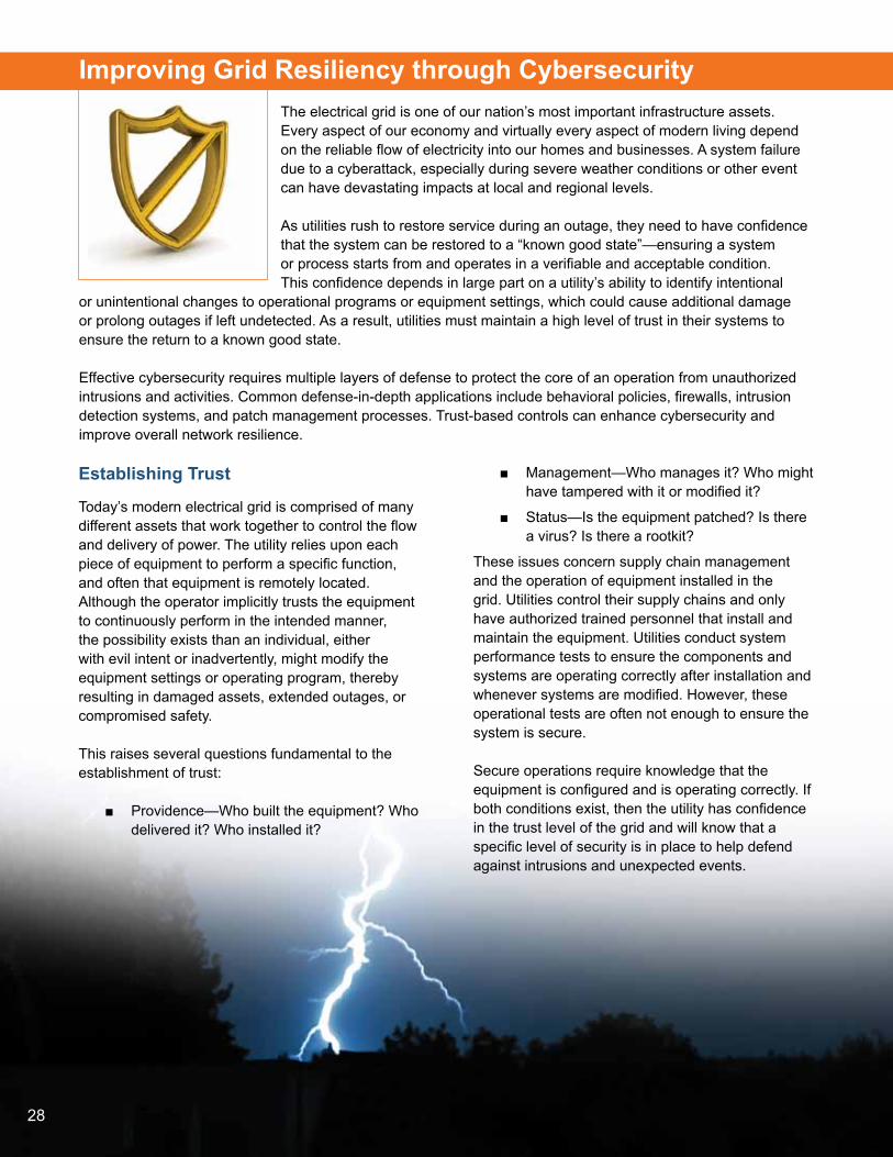
Improving Grid Resiliency through Cybersecurity The electrical grid is one of our nation’s most important infrastructure assets. Every aspect of our economy and virtually every aspect of modern living depend on the reliable flow of electricity into our homes and businesses. A system failure due to a cyberattack, especially during severe weather conditions or other event can have devastating impacts at local and regional levels.
As utilities rush to restore service during an outage, they need to have confidence that the system can be restored to a “known good state”—ensuring a system or process starts from and operates in a verifiable and acceptable condition. This confidence depends in large part on a utility’s ability to identify intentional
or unintentional changes to operational programs or equipment settings, which could cause additional damage or prolong outages if left undetected. As a result, utilities must maintain a high level of trust in their systems to ensure the return to a known good state.
Effective cybersecurity requires multiple layers of defense to protect the core of an operation from unauthorized intrusions and activities. Common defense-in-depth applications include behavioral policies, firewalls, intrusion detection systems, and patch management processes. Trust-based controls can enhance cybersecurity and improve overall network resilience.
Establishing Trust
Today’s modern electrical grid is comprised of many different assets that work together to control the flow and delivery of power. The utility relies upon each piece of equipment to perform a specific function, and often that equipment is remotely located. Although the operator implicitly trusts the equipment to continuously perform in the intended manner, the possibility exists than an individual, either with evil intent or inadvertently, might modify the equipment settings or operating program, thereby resulting in damaged assets, extended outages, or compromised safety.
This raises several questions fundamental to the establishment of trust:
■■ Providence—Who built the equipment? Who delivered it? Who installed it?
■■ Management—Who manages it? Who might have tampered with it or modified it?
■■ Status—Is the equipment patched? Is there a virus? Is there a rootkit?
These issues concern supply chain management and the operation of equipment installed in the grid. Utilities control their supply chains and only have authorized trained personnel that install and maintain the equipment. Utilities conduct system performance tests to ensure the components and systems are operating correctly after installation and whenever systems are modified. However, these operational tests are often not enough to ensure the system is secure.
Secure operations require knowledge that the equipment is configured and is operating correctly. If both conditions exist, then the utility has confidence in the trust level of the grid and will know that a specific level of security is in place to help defend against intrusions and unexpected events.
29
Determining Consistent Operation of Equipment
When a utility powers up complex equipment, the operator must have confidence that the asset will consistently perform in a known good state. To achieve this, modern equipment often includes a trusted platform module (TPM) to control the device’s boot sequence. A TPM is an integrated circuit that measures the software resident in the equipment when it starts.
At power-on, a TPM will measure and validate the startup code by taking a “hash” on the file and comparing it to a known good hash prior to allowing program execution. A cryptographic hash function is an algorithm that takes a block of data, such as a file or program, and returns a unique number that is similar to a long serial number. The (cryptographic) hash value establishes the identity of the device, with any subsequent changes to the data or program resulting in a change to the hash value. By comparing the measured hash value to the known value, the TPM can identify code modifications and alert the utility operator, who in turn will determine if the equipment should be permitted to come online. TPM functionalities can ultimately improve a utility’s situational awareness and strengthen the resilience of its networks to a range of threats.
Configuration Control
Controlled equipment configuration consists of two activities: establishing operational parameters and updating embedded software. Equipment operators need to know if and when operational parameters change and fall out of tolerance limits. Utilities also need the capability to remotely and automatically update embedded software as security patches become available.
Currently, most utilities manually configure and update embedded software, either in their center or by sending a technician to the field. This is a slow and costly process that often results in multiple revision levels running across a utility’s equipment base. Historically, utilities have been slow to implement timely updates.
By deploying a modern two-way communications network, a utility can remotely configure a device’s operational parameters and continuously monitor that equipment for anomalies or changes to settings. If such events occur, the control center is automatically notified and an operator is assigned to determine a course of action.
In this scenario, the operational center maintains the configuration of all devices in a central secure database. As unauthorized change alerts are received, the utility staff can take action to determine the appropriate next steps including remotely pushing the correct configuration settings back out to the device. If an authorized technician changes the device in the field, the utility staff in the control center can pull the configuration from the reprogrammed device and update the central repository with the new configuration. As with TPM functionalities, configuration control can improve utility response time to unexpected events and improve system resiliency.
30
Software Updates
Vendors periodically release updates to the software programs that run utility systems and equipment. As in the case of current configuration control practices, utilities typically dispatch a technician to the field to manually update the devices. This leads to a similar problem of multiple software versions running across a utility’s equipment base.
Using the same communications network described above, utilities can remotely update field devices from the control center. This process can be secured through a combination of vendor-specific private key certificates and embedded public key certificates. Specifically, a software vendor will digitally sign a software update with a unique private key certificate. By using the vendor’s public signing key, the utility can verify that the software update came from that vendor and was not altered in transit. The vendor will also embed the public key certificate of authorized users in the hardware prior to shipping. This methodology of certificates enables a device to verify a user’s signature prior to accepting a software update, thereby introducing an additional trust-based control to the utility’s operations. To avoid the simultaneous operation of inconsistent software versions, the system that updates the embedded software must function in a full transactional mode. This allows an operator to specify a group of devices to be updated with a single software package. At the end of the updating process, all equipment will be running the same revision level; however, if one device fails to update, all of the devices roll back to their previous version to ensure consistent and reliable operations.
Roadmap Recommendations
Utility operators should consider establishing trust in the equipment on their systems in order to improve grid resiliency. While trust-based controls are typically designed to defend against cyber-based threats, these same controls can drastically enhance a utility’s ability to detect and recover from equipment anomalies or system integrity problems, especially during weather-related events.
To establish an appropriate level of trust, utilities should focus their efforts on three activities:
■■ Ensure that equipment consistently starts in a known good state through the use of TPM and software verification techniques.
■■ Deploy an automated secure communications network to control and update equipment operational configurations.
■■ Utilize the secure communications network to conduct transaction-based software updates of field devices.

31
The Power of MicrogridsThe aftermath of Superstorm Sandy reminds us of the fragile nature of the U.S. power infrastructure and its inability to withstand high levels of stress. Moreover, once infrastructure is broken, the time required to repair it greatly compounds a lack of safety, comfort, and efficiency. Even considering highly evolved processes—utility crews from around the nation converging on affected areas—the days and weeks that follow are very costly to cities and communities.
The widespread destruction to the grid caused by Sandy is reinforcing creative thinking about resilience. Now that power has been restored, rebuilding can accelerate in the hard hit areas, especially New York and New Jersey. Governors Andrew Cuomo and Chris Christie say that we need to do it smarter; and they couldn’t be more correct. Leveraging this opportunity to deploy even smarter grid
technologies that increase energy security, improve efficiency, and often improve air quality, too, is essential. There are cost-effective solutions that can deliver multiple benefits at scale.
Microgrids are essentially miniature versions of the electric grid that include localized generation and storage. They offer the capabilities to “island” and run parallel to the macrogrid or sustain energy delivery from local generation if the grid is not available. Offering reliability and stability as well as renewable integration, microgrids command a harder look.
The concept of the microgrid goes back to 1882 when Thomas Edison developed the first power plant—the Manhattan Pearl Street Station—as the first source of power before the electric grid as we know it was even established. The technology has certainly evolved since then, but the fundamental concept remains the same.
Safety and prosperity depend on the modern grid more than ever, but it is routinely rocked by natural disasters. Volatile weather may cause power outages of up to two weeks. These outages cost millions of dollars and put lives at risk. In fact, the Department of Energy (DOE) estimates that the U.S. spends more than $26 billion annually on outages of more than five minutes. While the U.S. grid is good, its reliability does not compare well to other industrialized nations in Europe and Asia. Backup generation helps, but too often the emergency fuel is exhausted before the grid is restored.
For reliability, a compelling feature of microgrids is their ability to island, or separate from the grid. Localized and increasingly clean generation allows the microgrid to provide power to campuses and small communities independent of a macrogrid. These stability islands can keep whole communities of rate payers warm, fed, and safe. Importantly, microgrids allow first responders to start their work sooner. Of course, emergency services, communications, shelters, fuel movement, and supermarkets cannot tolerate weeks without the grid. Community microgrids can be a super set of emergency power systems that use and ration this distributed generation through pre-arranged plans and automated controls.
After Sandy, universities such as New York University and Princeton demonstrated how well-managed cogeneration systems kept campuses running for nearly two days.
Microgrids, Energy
Storage, and Decentralized
Generation

32
Other innovators are demonstrating the power of microgrids, too. Jose Marotta, senior engineer at Tampa General Hospital, has been to school on hurricanes. After all, Florida experienced more than four hurricanes in 2004. Responsible for the large Level 1 trauma center and an 11 MW campus, Mr. Marotta, routinely watches the weather and grid conditions, islanding intentionally to protect the facility’s mission. Mr. Marotta’s team is not only improving the trauma center’s capacity, but also its fault tolerance from external and internal events. Application of modern power management and automatic controls makes his team’s work consistent and the system dependable.
A microgrid can be improved by fuel diversification. Tampa General’s microgrid may draw from grid power, diesel-fueled generators, and perhaps in the future clean, natural gas-fired cogeneration.
Cogeneration and emergency generation are increasingly used to anchor local renewable generation sources as well. Renewables that are always “on” are grid-tied, meaning they must go offline when the electrical grid is disrupted. When the microgrid islands, the anchor resource provides a stable source of voltage and frequency, which makes these grid-tied resources transition to microgrids. This happens regardless of macrogrid availability. Other features of microgrids are sophisticated switching between diverse sources and “black start” capability. If power is disrupted, restoration of the ancillary systems providing lubrication, cooling, and starting current are necessary to restart generation or cogeneration.
By bringing generation closer to the loads, we can achieve a higher penetration of renewables, mitigating costly grid modifications to manage the intermittent nature of renewable energy. Diverse energy sources or energy storage can fill supply gaps due to a lack of sun or wind.
Further, the storage element and its high-speed power electronics can make the microgrid more fault-tolerant. Energy efficiency and project economics are being improved by gas-fired cogeneration, combined heat and power (CHP), and renewable energy:
■■ Natural gas prices are less than one-third of recent peaks.
■■ When a facility needs heat, the heat from local generation is far easier to deploy in the form of hot water or process heat.
■■ Absorption chillers can be paired with CHP to cool data centers and buildings.
■■ Localized generation mitigates the up to 7 percent electrical transmission and distribution losses reported by the Energy Information Administration.
Recent projects seek to further monetize microgrids through participation in the ancillary services market. By providing local power for peak demand and regulation services, microgrid owners are capturing credits and reducing rates.
But there is more to do. Permitting, codes, and standards must continue to evolve to enable the new generation technologies. Special rate structures for “certain power” must be approved by public utility commissions. The important work on IEEE 1547 Standard for Interconnecting Distributed Resources with Electric Power Systems must continue. It is important for more utilities to adapt to and embrace the microgrid momentum.
While upfront costs, pricing, and regulation are being managed, increased collaboration with utilities, public utility commissions, and public-private partnership will help the technology reach its wide-scale potential. Pike Research predicts that more than 3.1 GW of microgrid capacity will be available by 2015. Some states are piloting initiatives alongside DOE, but we need to continue to build awareness around the technology.

33
Energy Reliability with MicrogridsThe U.S. power delivery system’s complex network of substations, transmission lines, and distribution lines are not designed to withstand or quickly recover from damage inflicted simultaneously on multiple power system components. We’ve seen this in recent years during weather-related events such as Hurricane Irene and Superstorm Sandy.
The number and duration of power outages in the U.S. continue to rise, driven primarily by weather-related incidents. The average outage duration in the U.S. is 120 minutes and climbing annually. The outage duration total in the Midwest is 92 minutes per year and 214 minutes in the Northeast. By contrast, outage duration for the rest of the industrialized world is less than 10 minutes per year
and getting better. For example, Japan averages only four minutes of interrupted service each year. The growing prevalence of physical and cybersecurity threats also pose significant challenges for organizations’ mission-critical operations in ensuring reliable access to power supplies.
Historically, when a disaster strikes the result is infrastructure improvements to address the specific cause of each power failure. Many times, planning fails to anticipate future emergencies. A large earthquake, nuclear explosion, or terrorist attack could cause suffering and disruption over a much larger area than a hurricane. Establishing safe haven enclaves to serve as bases of rescue and recovery could go a long way to address the human and economic impacts of future, unanticipated events.
When an outage strikes, the effects often stretch far beyond the initial impact zone. Regional outages inhibit the ability to protect those in danger and provide basic needs such as food, sanitation, and shelter. We could recover more quickly if islands within each area could maintain power and serve as centers for critical services and recovery.
Standby and backup diesel generators are often the only power source available. However, backup generators pose some problems:
■■ They typically serve only the buildings they are attached to, so nearby buildings do not get power.
■■ They often have less than 72 hours of diesel fuel in their tank. Fuel deliveries may be significantly delayed.
■■ They are often sized for the maximum load and do not use fuel efficiently when loads are much less.
Solution—Microgrids
To optimize available generation and make power available to a larger area, microgrids offer a viable solution during sudden power outages.
A microgrid can isolate itself via a utility branch circuit and coordinate generators in the area, rather than having each building operating independently of grid and using backup generators. Using only the generators necessary to support the loads at any given time ensures optimum use of all the fuel in the microgrid area.
34
A microgrid can integrate a number of features beyond backup diesel generators. Features include:
■■ alternative energy sources such as wind and solar
■■ gas turbines and central plants providing combined heat and power
■■ energy storage in batteries and electric vehicles
The microgrid senses loads and fault conditions and can reroute power to as many critical areas as possible given any situation. In that way, it is “self-healing.”
Thus, we define a microgrid as comprising four key elements:
■■ local electricity generation
■■ local load management
■■ ability to automatically decouple from the grid and go into “island mode”
■■ ability to work cohesively with the local utility
Backup generators only support loads immediately attached to them and they usually come into action during utility power outages. On the other hand, a microgrid consists of onsite generating sources that may include different combinations of diesel generators, gas turbines, fuel cells, photovoltaic and other small-scale renewable generators, storage devices, and controllable end-use loads that enable a facility to operate in a utility-connected mode as well as island mode, thereby ensuring energy reliability.
Key Challenges
There are two key challenges to making microgrids work: utility interconnection and microgrid controls.
Utility Interconnection
While having the capability to operate in island mode is a defining feature of a microgrid, the local electricity generators within it are usually connected to the utility grid. This allows a facility to purchase energy and ancillary services from the utility, and sell locally generated electricity back to the utility grid during times of peak demand. When the microgrid is operating with the utility grid, the utility is responsible for frequency and voltage stability. The microgrid control system needs to operate the generators and loads within it in order to maintain consistent power flow. Microgrids should be coordinated with utility grid management to minimize risk of transmission disruption or danger to line workers and others exposed to power currents. Therefore, a utility-microgrid interconnection agreement allowing two-way power flow needs to be developed for each microgrid.
Microgrid Controls
A successful microgrid must have intelligent methods to manage and control all loads. Energy sources have defined output capacity and if overloaded, will severely distort the voltage output or completely shut it down. When a microgrid separates from all of the generation capacity of the grid and relies solely on local generation, management of all loads must be established to properly balance the power generation capacity. This is extremely critical whether a given site has multiple generation sources or simply more load demand than available local power generation. As local generation capacity is ramped up, the loads are also brought online in an intelligent predefined strategy. Typically, critical loads come first and other loads are adjusted to never overload available generation capacity.

35
There are many approaches to controlling loads, at a building feeder level, circuit level, or discrete level. However, the load manager must be able to turn off power quickly and when restoring power, know the capacity so the generator isn’t overloaded.
Microgrid control is relatively easy when all generation resources within it are in close proximity, such as a central utility plant on a college campus. In a distributed microgrid where generation sources (e.g., backup generators) are connected to distribution circuits spread across a large geographic area, voltage and frequency regulation is extremely important. Generators of different sizes and response behaviors can’t simply be hooked up and synchronized over a large area. Such a grid would be unstable as generators on the distribution circuit react to one another by picking up and dropping their share of the load. A supervisory strategy needs to be employed with central controls to ensure stability. The effects can be minimized in a newly designed grid, but most microgrids will be cobbled together with existing generators that have a wide variety of vintages and behaviors.
Microgrid design and operation require extra focus on safety. If the utility is down in one area, it does not necessarily mean that all branch circuits will be blacked out. Safety dictates that everyone be aware of the possibility that microgrids could re-energize loads under the microgrids’ control.
Campuses, military bases, and waste water treatment plants are good candidates for a distributed microgrid. They often have a common mission and are managed by the same organization—facilitating coordination. Often, they also have central plants that can be used for base loads over a broad area with distributed generators. These types of generators are used when loads are too low to justify running the central plant or to support the central plant over a larger area.
Applicability and Benefits
A microgrid approach makes sense for many organizations, primarily those that have a high demand for energy in their facilities and where loss of critical operations poses a significant risk of revenue loss, data loss, or safety and security. Microgrid candidates include:
■■ military bases where power shutdown would pose unacceptable security risks
■■ federal facilities, including research laboratories, where wavering energy reliability could mean loss of data and millions of dollars in lost time
■■ hospitals that need to seamlessly deliver patient care, regardless of weather or other conditions
■■ large data centers that are the heart of most organizations’ business operations
■■ research-driven colleges and universities that need to safeguard and maintain years of faculty work
■■ local governments that need to offer operational assurance to large businesses in their district, as well as attract new companies for stronger job creation
■■ commercial campus settings where 24/7 power reliability is crucial for protecting long-term investments such as research and development
■■ a densely populated urban area, such as Manhattan, where concentration of energy use is high and significant scale justifies connecting multiple buildings as part of a microgrid network
■■ instances where bringing in new electrical lines to meet a facility’s power requirements will be cost- and time-prohibitive to the organization and local utility
36
Distributed microgrids provide additional benefits to utility operators by integrating renewable resources in distribution circuits. Today, utility distribution circuits are not designed to absorb large amounts of distributed or renewable generation. If microgrid operators can integrate renewables such as rooftop solar while providing frequency and voltage stability, their jobs becomes easier.
Vision
One can envision that a resilient and robust utility infrastructure of the future can be built out of interconnected microgrids at universities, hospitals, industrial parks, and neighborhoods. Individual microgrids would be nominally connected to form a single utility grid but could also isolate from the grid and operate independently in case of disruptions. Moreover, this would enable easier integration of distributed and renewable generation.

37
The Role of Energy Storage in Disaster Recovery and PreventionFrom flashlights to uninterrupted power supplies, energy storage assets have a long history of supporting critical infrastructure and services during times of natural disaster. By providing power and lighting during large-scale weather events such as Superstorm Sandy and Hurricanes Irene and Katrina, energy storage systems of all shapes and sizes reduce the time it takes for first responders to begin recovery efforts. Unfortunately, while extremely valuable when needed, most energy storage assets remain idle for long periods of time and are viewed as “sunk” costs without the ability to generate revenue. Furthermore, many energy storage systems require mandatory and ongoing maintenance procedures, which if not completed properly, put the entire performance of the systems at risk.
Today, emerging technologies in the energy storage field are changing this paradigm. Rather than representing fixed costs, energy storage systems are transforming into active assets that can be used to create sustainable revenue streams. Whether through participation in new energy markets recently opened by the Federal Energy Regulatory Commission (FERC), or through their inherent ability to extend life-cycling capabilities, these new energy storage systems are poised to lower operating costs by reducing peak demand charges, increase onsite power generation efficiency, and extend emergency generator run-times. It’s a new approach that enables energy storage—once a costly, passive (but necessary) disaster recovery asset—to emerge as a cost-effective, active participant that stands to make power systems and consumer services more resilient, more efficient, and more responsive to the need for a sustainable, readily-adaptable energy environment.
One such example of an emerging energy storage technology is the recent introduction of sodium-nickel-based batteries to the marketplace. With 4,500 full depth of discharge cycles, multi-layered safety features—including the core chemistry, triple-encased steel packaging, and redundant controls with remote diagnostic capabilities—these batteries enable end users to reduce daily operational costs and, when the next disaster strikes, provide an additional level of resiliency to the electrical grid or host facility.
This type of battery design is a clear departure from traditional battery technologies. Using a sodium-nickel-based chemistry, the cells inside the battery operate at elevated temperatures. These elevated temperatures help immunize the battery from extremes in the ambient temperature environment.
The battery package surrounding the cells contains a highly-effective thermal insulation which minimizes thermal power losses and improves safe operation across a broad range of applications. The battery’s long life originates in its solid electrolyte which experiences negligible degradation over battery service life, even at deep discharges and high cycle volumes. When fully-integrated into existing power infrastructure or used in grid modernization efforts, this battery technology can have a major impact on how well an area manages a catastrophic event, simultaneously providing a means of controlling costs during day-to-day operations.

38
Emerging Markets for Energy Storage
New energy storage system designs offer safer and longer operational lifespans, as well as allow customers to install large battery systems that provide emergency power to critical functions when the electrical grid fails. Equally important is their capacity to produce revenue and reduce costs during normal operation. Recent FERC orders have enabled battery systems to participate in the wholesale energy markets and perform such actions as frequency regulation, energy arbitrage, and even demand response functions. NYISO6 and PJM7 have enabled energy resources to participate in their energy markets, and multiple battery installations are creating revenue that supports these installations. Additional examples of this new approach are outlined below.
Utility Deployment
Utilities are continuing to exploit new battery technology’s enhanced safety and lifespan capabilities by installing batteries at substations and in community energy storage systems. Battery systems help to provide efficient use of utility resources by extending their peak demand capabilities. In addition, during periods of grid stress, these energy storage stations can provide either the substation or the larger community with valuable extended operating power to allow end users to charge their communications equipment or even their vehicles.
Behind the Meter Applications
Retail customers, including large pharmaceuticals, manufacturing plants, and office complexes, are turning to energy storage systems as a cleaner, more cost effective way to manage their peak demand and peak energy charges.
In the event of a power outage, these systems are designed to operate as an uninterrupted power supply, and provide seamless power to critical infrastructure.
For example, since the earthquake and tsunami disaster in March 2011, Japan has been a major proponent of this approach.8 Energy storage deployment between utilities and homes has emerged as a key component of their recovery and rebuilding effort.
Combined Heat and Power and Microgrids
Another means of leveraging the value of active energy storage systems is to integrate them with other onsite power systems. The integration of batteries with a combined heat and power system, for instance, has the potential to create a safe, resilient, and efficient energy campus microgrid. In this scenario, natural gas-powered engines provide the facility’s base electrical needs. Additionally, by leveraging the engine’s high-temperature exhaust, it meets the facility’s heating and cooling needs. The battery charges when the electrical load is low and discharges when the facility’s load exceeds that of the engine’s capabilities, thereby providing the much needed additional power capacity for the microgrid. During outages, the battery system is configured to work alongside the generator backup system to optimize generator runtime and increase fuel efficiency.
Backup Power—Diesel Fuel Use Reduction
In remote grid telecom applications, advanced technology battery systems have already proven their ability to nearly double the efficiency of the diesel generators they support.9 This reduction in fuel use has a positive impact on the user’s operating costs, but also serves to reduce fossil fuel consumption overall.
______________________________6 New York Independent System Operator7 A regional transmission organization8 Energy Storage: Asian Systems and Apps. Smart Grid Insights, August 2012 (www.smartgridresearch.org)9 Sodium-Metal Halide Batteries in Diesel-Battery Hybrid Telecom Applications. General Electric Company, 2011 (http://geenergystorage.com)

39
______________________________10 Diesel: The Lifeblood of the Recovery Effort. Data Center Knowledge, 2012 (www.datacenterknowledge.com)
During extended outages or natural disasters, the supply of diesel fuel can become severely limited. Although cell towers and data centers support many critical communications services, they aren’t alone in needing priority access to fuel. Other consumer services can be impacted as well.
When New York University’s Langone Medical Center experienced backup generator failure during Superstorm Sandy10, it prompted a mass evacuation of patients from the facility. An energy storage system could not only provide backup power support to a health or emergency facility, but it could also reduce an existing generator’s diesel fuel usage as a whole, extending services to those who need it most.
Energy Storage Vision for Rebuilding
Deploying energy storage below the grid will increase grid resiliency, promote greater efficiency and more sustainable energy generation. By increasing the amount of energy storage nationwide, the ability to incorporate larger penetrations of sustainable, but variable, energy sources would be enhanced.
Power Plants
By deploying correctly-sized energy storage at power plants, black-start capabilities will become more widely available for use as needed. On an ongoing basis, these energy storage systems will be able to increase revenue by participating in ancillary services or energy markets.
Substations
System deployment at substations can provide required overload support when the equipment is aging or if there is substantial load growth due to unexpected increased demand. Energy storage systems could also provide daily voltage and ancillary services support, thereby providing a solid revenue stream.
Critical Infrastructure
Critical infrastructure such as police command centers, fire stations, cell towers, and hospitals often have diesel generation as backup power. By deploying energy storage systems at these facilities, the diesel system can be optimized to decrease generator runtime. New energy storage battery technology deployed at remote communication stations has already proven that the runtime capability of a single unit of fuel can be raised by almost a factor of two when the battery is continuously paired with a diesel engine. The energy storage component can then also be used on a daily basis to reduce the facility’s total energy bill by reducing energy purchases during peak times, and reducing energy and demand charges.
In addition, designated community, communication, cooling, or heating centers located on campuses, convention centers, or other public facilities can be enhanced by updating infrastructure and incorporating energy storage systems to provide support during outages. These facilities can also leverage energy storage to reduce their energy costs by leveling peak demand and peak energy charges.
Conclusion
Energy storage has traditionally been viewed as an expensive “must-have” for disaster recovery efforts. While recent events support the importance of grid modernization through energy storage systems—the idea that these systems could be used to generate revenue streams and reduce operating costs is a newer concept. Emerging battery technologies, however, prove that energy storage can simultaneously and safely create ongoing value and provide support in times of crisis.

40
Integrating Energy Storage into the Distribution SystemEnergy storage systems can reduce thermal strain on the grid during peak load periods and provide a reliable backup power supply during grid outages. These systems make the grid more resilient to damage caused by extreme weather, natural disasters, and cyberattacks. In addition, energy storage systems, when coupled with renewable energy sources, can help electric utilities meet peak demand requirements without the need for additional conventional generation from burning fossil fuels. Superstorm Sandy caused major damage to the infrastructure used to transport fuels including the natural gas used in gas-fired backup generators.
Large-Scale Energy Storage Systems
Large-scale energy storage systems allow electric utilities to better utilize renewable generation produced by commercial wind and solar plants. These systems, installed at collector substations, can provide megawatt-hours of energy storage and include controls that permit this power to be dispatched when it’s needed the most—during periods of peak usage. Large-scale systems dramatically reduce greenhouse gases by deferring, or eliminating, the need for additional generation produced by traditional generating sources. These systems displace peak energy costs with off-peak costs.
There are greater demands for electricity at certain times of the day. The grid can add more generation, charge time of use, or provide technology that “shaves” the peak. This is commonly referred to as peak shaving. The peak-shaving capability of large-scale energy storage systems is especially valuable during heat waves when high electricity demand and with high temperatures can cause significant thermal strain to power grid equipment. Such thermal strain can shorten the life of power grid assets and lead to equipment failures that result in outages.
Large-scale energy storage systems can also supply an immediate source of backup power in the event a major storm, other natural disaster, or cyberattack results.
Large-scale energy storage systems can be combined with a fault location, isolation, and restoration (FLISR) system to achieve dynamic islanding upon the loss of power to the feeder from the serving substation. Service is restored to the maximum number of customers based on load information captured by the FLISR system before the loss of power, and the amount of energy available in the battery. The island is minimized as the battery is depleted and/or power is restored to the feeder.
Small-Scale Energy Storage Systems
Small-scale energy storage systems use pad-mounted energy storage units distributed along residential feeders at the edge of the power grid. These battery-based units permit the integration of the community’s intermittent renewable generation resources—such as rooftop photovoltaic panels and wind turbines—into the grid, where these increasingly popular resources can be dispatched when needed.

41
The battery-based energy storage units can be aggregated to collectively provide peak shaving, improve power quality, and/or improve local voltage control to reduce losses and thus improve distribution feeder efficiencies. This aggregation of energy storage units can eliminate the need for costly, time-consuming infrastructure build-outs. Distributed energy storage can be a means for peak shaving since it doesn’t require customer involvement. The mesh communication system used to link the energy storage units can help the utility quickly find the site of a problem on the distribution system without first dispatching a crew to locate it.
The energy storage units offer reliable, local backup power for consumers as well. The close proximity of the energy storage units to consumers helps ensure the availability of supplemental power in the event of an outage. A typical 25-kVA energy storage unit can offer supplemental power to several homes for up to three hours—more than sufficient for the duration of many outages. They can also be deployed at traffic signals and used for emergency lighting, emergency communications, and more.
A fleet of larger-capacity energy storage units—typically rated 250 kVA—distributed throughout the grid can support hundreds of homes, small businesses, and critical infrastructure during an outage. When combined with the community’s renewable generation resources, the resultant microgrid is capable of operating for many hours or even days. Groups of these larger-capacity energy storage units can be arranged as “virtual power plants” and suitably planned to be storm-ready in anticipation of an outage. With the deployment of virtual power plants, utility crews can concentrate on service restoration elsewhere on the system.
The distribution grid, transformed into microgrids, offers an additional benefit: increased resilience to potential cybersecurity attacks.
Example Results of a Large-Scale Energy Storage System
Electric service in Presidio, Texas, is supplied by a troublesome, difficult-to-access 69-kV line. Repairs to this line frequently take a long time. Because of its limited connection to the grid—and its high summer and winter peak loads—Presidio often experiences protracted power outages, especially from storm-related damage.
To improve power quality and reliability, the serving utility, AEP, procured a large-scale energy storage system which they applied in conjunction with a distributed-intelligence FLISR system to provide dynamic islanding for the entire town. The energy storage system has substantially improved power quality and decreased the number of outages experienced by utility customers in the Presidio area.
Small-scale community energy storage projects have been deployed in the United States, the United Kingdom, New Zealand, and elsewhere.
Roadmap Recommendations
Implementation of an energy storage system typically involves several steps, including:
■■ performance of analytical studies to determine the energy storage solution which will maximize reliability and availability of the grid
■■ appropriate planning and procurement services to ensure timely project completion
■■ a communication site survey to ensure acceptable signal strength between radios installed in the energy storage units
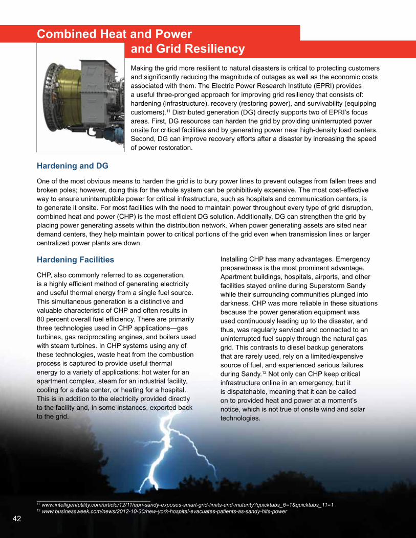
42
Combined Heat and Power and Grid ResiliencyMaking the grid more resilient to natural disasters is critical to protecting customers and significantly reducing the magnitude of outages as well as the economic costs associated with them. The Electric Power Research Institute (EPRI) provides a useful three-pronged approach for improving grid resiliency that consists of: hardening (infrastructure), recovery (restoring power), and survivability (equipping customers).11 Distributed generation (DG) directly supports two of EPRI’s focus areas. First, DG resources can harden the grid by providing uninterrupted power onsite for critical facilities and by generating power near high-density load centers. Second, DG can improve recovery efforts after a disaster by increasing the speed of power restoration.
Hardening and DG
One of the most obvious means to harden the grid is to bury power lines to prevent outages from fallen trees and broken poles; however, doing this for the whole system can be prohibitively expensive. The most cost-effective way to ensure uninterruptible power for critical infrastructure, such as hospitals and communication centers, is to generate it onsite. For most facilities with the need to maintain power throughout every type of grid disruption, combined heat and power (CHP) is the most efficient DG solution. Additionally, DG can strengthen the grid by placing power generating assets within the distribution network. When power generating assets are sited near demand centers, they help maintain power to critical portions of the grid even when transmission lines or larger centralized power plants are down.
______________________________11 www.intelligentutility.com/article/12/11/epri-sandy-exposes-smart-grid-limits-and-maturity?quicktabs_6=1&quicktabs_11=112 www.businessweek.com/news/2012-10-30/new-york-hospital-evacuates-patients-as-sandy-hits-power
Hardening Facilities
CHP, also commonly referred to as cogeneration, is a highly efficient method of generating electricity and useful thermal energy from a single fuel source. This simultaneous generation is a distinctive and valuable characteristic of CHP and often results in 80 percent overall fuel efficiency. There are primarily three technologies used in CHP applications—gas turbines, gas reciprocating engines, and boilers used with steam turbines. In CHP systems using any of these technologies, waste heat from the combustion process is captured to provide useful thermal energy to a variety of applications: hot water for an apartment complex, steam for an industrial facility, cooling for a data center, or heating for a hospital. This is in addition to the electricity provided directly to the facility and, in some instances, exported back to the grid.
Installing CHP has many advantages. Emergency preparedness is the most prominent advantage. Apartment buildings, hospitals, airports, and other facilities stayed online during Superstorm Sandy while their surrounding communities plunged into darkness. CHP was more reliable in these situations because the power generation equipment was used continuously leading up to the disaster, and thus, was regularly serviced and connected to an uninterrupted fuel supply through the natural gas grid. This contrasts to diesel backup generators that are rarely used, rely on a limited/expensive source of fuel, and experienced serious failures during Sandy.12 Not only can CHP keep critical infrastructure online in an emergency, but it is dispatchable, meaning that it can be called on to provided heat and power at a moment’s notice, which is not true of onsite wind and solar technologies.

43
______________________________13 www.epa.gov/chp/basic/efficiency.html14 www.dailyfinance.com/2012/11/16/power-outages-after-hurricane-sandy-werent-unusually-long-after/15 nrg-concepts.com/rochester-international-airport/16 nrg-concepts.com/cogeneration-chp-plants-keep-the-lights-on-for-thousands-during-sandy/
There are non-disaster benefits of installing CHP systems as well. Due to the utilization of waste heat, these systems often achieve efficiencies of 70 to 80 percent, significantly higher than producing the heat and electricity separately, which has average levels of efficiency of 40–50 percent in the U.S.13 Higher total efficiencies result in lower fuel usage, decreased energy costs, and reduced emissions. Additionally, CHP systems utilize low-priced, domestically abundant natural gas. This makes CHP a valuable asset to reduce a facility’s energy costs, even without considering the benefits it will provide when a facility is weathering a disaster.
While Sandy severed power to millions across the eastern U.S., CHP kept the lights on at a number of facilities. In New Jersey where more than 2.6 million lost power—more than 65 percent of total utility customers14—the CHP plant at Princeton University provided steam and electricity to the university community of around 12,000 people throughout the storm while the surrounding community remained without power. The plant, which runs on natural gas, uses an aeroderivative gas turbine (a modified jet engine) and provides one of the highest levels of reliability.
Further upstate, a CHP plant employing a different technology (reciprocating gas engines) at Rochester International Airport was also able to maintain power among widespread outages in the region as Sandy moved further inland.15 There are numerous other examples of CHP keeping the lights on during Sandy for tens of thousands in just New York City alone, from apartment and university facilities in Manhattan to large residential complexes in the outer boroughs.16
Hardening Distribution Grids
Strategically placing power generation assets within a distribution grid is an effective way to ensure uninterrupted power for many customers who are unable to build their own CHP plants. A recent example is the case of New York Power Authority’s (NYPA) Power-Now sites. In early 2000, NYPA implemented six widely distributed power generation sites throughout the city near major load centers. Equipped with ten aeroderivative gas turbines, they can provide more than 450 megawatts of power. The plants kept running through Superstorm Sandy and delivered critical voltage stability to the New York City grid. Prior to Sandy, these units proved their worth in the wake of the September 11, 2001, terrorist attacks. The New York Independent System Operator, which runs the state’s transmission system, limited deliveries of electricity into the area from upstate plants. On another occasion—during the Northeast blackout in August 2003—the plants helped return power to New York City while stabilizing the downstate transmission system.
Recovery and DG
After a natural disaster hits, the priority for the electric grid is to restore power to parts of the system that were damaged, severed, or otherwise left powerless. Typically, this takes the form of repairing damaged lines and bringing power plants back online that were shut down as a result of the disaster. However, there are circumstances where plants cannot be brought back online easily or transmission lines are damaged beyond simple/rapid repairs. This can result in leaving large swaths of customers in the dark for days or require forced energy reductions that can last for weeks or even months after the disaster occurs.

44
In these situations, a very effective solution is to have a fleet of mobile, trailer-mounted power plants that can be rapidly deployed to areas with the largest or most critical power needs. This type of solution uses proven technology, such as gas turbines and reciprocating engines, which can quickly connect to and provide power for an existing grid. For example, after the Fukushima earthquake and tsunami damaged transmission lines and brought numerous power plants offline in Japan, trailer-mounted gas turbines were a critical part of the strategy that helped prevent widespread blackouts in the summer of 2011.
The advantages of an energy-dense fleet with a small footprint that has natural gas or dual fuel capabilities is that it:
■■ can be connected to the buried and undisturbed natural gas grid, and
■■ can avoid liquid fuel supply issues that arise after a disaster (e.g., fuel shortages in New Jersey and New York after Sandy).
Additionally, utilities can improve recovery for residential, commercial, and industrial areas by rapidly bringing in power-generating fleets, which bypass more drawn out transmission restoration efforts.
Takeaways and Next Steps
DG is a critical component of grid resiliency investments because of its ability to harden the power system and improve recovery efforts after disasters.
■■ Hardening of a facility: CHP should be used to provide uninterrupted power because it is dispatchable, does not rely on liquid fuels, and has non-disaster related benefits including lowering energy costs and reducing emissions. Additional funding and policy incentives are needed to spur private sector investments.
■■ Strategic locations: DG assets should be placed in strategic locations within distribution networks, specifically, near high density load centers.
■■ Recovering from a disaster: To prevent long-term power outages, mobile DG technologies (e.g., trailer mounted gas turbines and reciprocating engines) need to be deployed to help get power to customers quickly by providing emergency/bridge power before the grid is fully restored.
■■ Government involvement: Government leaders at the federal, state, and local levels should focus resources on infrastructure that includes DG applications as part of a larger strategy for a more resilient grid.

45
Key to Staying Connected is DisconnectingIn the days, weeks, and perhaps months post Superstorm Sandy, it has become evident that the grid we rely on for virtually everything is incredibly susceptible to unkind acts. In this case it came from Mother Nature. It is in these moments that the simple things we take for granted, such as lighting, are not so simple to restore.
The utility companies struggled to restore services, but what if fundamental needs like lighting could be upgraded to disconnect and be maintained as an “island” (off-grid use) until normal service is restored? Public lighting, buildings, and communities can be disconnected to protect them from systemic failures and provide power to run essential services, mitigating the impact of catastrophic
events. Technologies exist today that will allow for this, but it requires a wholesale change in thinking, preparation, and public-private partnership.
Lighting can direct the path to recovery. Rather than evaluating lighting solely on the utility costs of power (kilowatt hour) and its efficiency to produce light from energy consumed (watts/square foot), we need to add an additional metric: reliability. Lighting’s reliability is dependent on the power’s quality and surety. Issues include not enough power, peak demand cutbacks, power blackouts and brownouts, rising costs, decreasing quality, increasingly negative consequences of extreme weather, and the threat of terrorism—foreign and domestic.
LEDs (light-emitting diodes) are generally thought of as being energy-efficient, but there are some basic characteristics to this technology that makes it ideally suited for adding reliability to a lighting system.
■■ In addition to being efficient, they have a very low power draw, which is important in times of power outages. By reducing the power draw, you can do more with less as well as extend the life of emergency backup systems such as batteries and generators.
■■ LEDs offer controllability—getting lighting where you want it, when you want it. They can be controlled by simple, yet effective digital controls that deliver the right amount of light, at the right place at the right time.
■■ LEDs are natively direct current (dc), allowing them to integrate with alternate sources of dc power which enables islanding.
While some electrical infrastructures may not survive the fury of a hurricane, street lighting that is based on alternate energy could be independent of the grid. In developing countries, this is already happening because the technology is leap-frogging the grid’s very existence. Much like the rapid adoption of cell phones, solar street lighting is becoming popular because it does not require infrastructure. With solar panels mounted to individual LED luminaires and the ability to store many days’ worth of power, this allows villages to have light in the absence of a grid or even in a natural disaster.
In the case of Sandy, while many street lights were ripped out of the ground, many were dark because of power outages. If these lights could work off alternate energy they had collected and stored, the impact it could have on recovery efforts would be immeasurable.

46
Because LED technology inherently requires less energy than traditional technologies and lends itself to dc power, municipalities could install solar or other backup power systems, which would allow first responders to have lighting and get to those in need. While not all street lighting may be operable, entire cities and towns would not have to be in the dark for days or weeks.
There are other scenarios that could be implemented gradually. For example, every other street pole in areas that are central to disaster relief—such as hospitals or shelters—could be replaced with battery backup systems. Municipalities could do several poles a year, eventually covering their entire town or city, without large, costly upfront investments. If funding is a challenge, often there is affordable private financing for these systems. The other advantage to these battery backup systems on low-powered LED lighting is a modular approach that could include adaptive dimming. This would not require full power to give citizens a sense of safety or comfort. Even dimmed lighting would give people a sense of hope while preserving energy and acting as beacons of light for first responders.
The controllability of LEDs tied into a centralized software system not only allow administrators to get lights on where they are still available, but also to see exactly where the lights are out. This gives them an idea of what areas were hardest hit and where they might want to direct first responders. Because these poles are islanded, they can also be used as communications beacons—distributing text information for emergency follow up or acting as a meeting place for those affected.
By extension, an islanded lighting pole may be dimensioned to provide enough local energy storage to periodically collect low bandwidth texting messages from cell phones and periodically transmit them to other communication networks, replicating a telecom site-cell but on a power diet. This would allow people to contact first responders and loved ones in the event of outages.
Another extension of this modular approach is allowing the LED lighting system’s backup power to energize cameras that are used for monitoring traffic, once again allowing city administrators to get a bird’s eye view into the situations and help guide first responders.
This approach can be applied to everything from your home to an office or apartment building. For instance, new legislation in New York City indicates that buildings be retrofit with more energy-efficient systems. This is a great opportunity to upgrade to LED lighting systems that use substantially less energy, while having the ability to operate on dc battery power, fuel cells, or as part of an in-building microgrid.
The ultimate asset of LED technology is that when it is not being islanded, it can still be used smartly. Because of its low energy draw and controllability, LEDs will use up to 80 percent less energy and provide better quality of light.
The investment is not only in energy-efficiency, but also a stepping stone to better position communities in the event of a disaster.

47
Backup Power Systems Onsite backup power provides a reliable and cost-effective way to mitigate the risk of economic loss and societal hardship from power outages. Many businesses suffer economic losses due to disruptions of electric power supply during a natural disaster. For businesses with highly sensitive loads such as data centers and financial institutions, the risk of economic losses from downtime is high. For many facilities, such as assisted living facilities and nursing homes, there is a life safety aspect to consider.
Other facilities, such as cell tower sites, emergency call centers, and gas stations, have far-reaching social impact and their availability is critical. Investment in onsite backup power equipment can ensure reliability, safety, and productivity.
Backup Power Systems: Brief Overview
Onsite backup systems use local generation at the facility site to provide power when the utility is not available. The backup power system may or not be interconnected with the utility grid. Onsite electrical power generating systems are readily available in a wide variety of designs for specific uses and customer applications. This type of power system consists of a power source and a means to transfer power from that source to the load when an outage occurs. Remote monitoring and control systems that allow an operator to check the system status and operate the system remotely are becoming more commonplace. The generator’s primary fuel source can be natural gas (NG), propane, or diesel.
Fuel selection: The selection of NG, diesel, or liquefied petroleum gas (LPG) should be made based on the application’s characteristics and requirements. Considerations for choosing among the different types include:
■■ equipment costs (initial and installation)
■■ fuel costs
■■ fuel availability
■■ equipment start up time
Design Considerations for Diesel Onsite Generator Systems
Designing a generator set installation requires consideration of equipment and application requirements. These vary depending on the reasons for having the generator set and used. Reviewing and understanding these reasons is an appropriate starting point for system design and equipment choices. No single solution meets all needs. Before configuring a system, facility managers should consider the intended use of the generator set and a number of other factors, as follows:
General requirements: Consider code requirements for emergency power and voluntary installations of standby power to mitigate the risk of loss of services, data, or other valuable assets. One system may be used for both of these general needs provided that life safety needs have priority.
Backup
Generation

48
Load-specific requirements: A wide range of specific requirements will result in the need for onsite electric generation systems which tend to vary by application type. Some common installations are:
■■ Healthcare: Standby power is required for all life-safety systems which include evacuation/egress lighting, HVAC systems for patient care and operating rooms, critical process equipment such as medical imaging devices, and fire suppression equipment to aid response teams in the event of an emergency.
■■ Data centers: The servers housed in data centers drive our economies and the financial health of businesses and households. Without a backup power system for these loads, the loss of data could cause a global catastrophe. Apart from the data held in these facilities, the cooling equipment required to maintain their operation must be kept online in order for the digital equipment to work properly.
■■ Communications: From cellular towers to 911 call centers, an efficient emergency response requires communication. Without power to transmitters and receivers, the storm recovery process is significantly delayed.
■■ Commercial/Residential properties: Ambient lighting, temperature control, and the computers that most of us rely on every day need sustained power in order to operate. Without electricity, even the most mundane tasks become points of concern, from sending an email to keeping food cold in the refrigerator.
Location: One of the first design decisions will be to determine whether the location of the generator set will be inside a building or outside in a shelter or housing. The overall cost and ease of installation of the power system depend upon the layout and physical location of all elements of the system—generator set, fuel tanks, ventilation ducts and louvers, accessories, etc. For indoor and outdoor locations, key considerations include:
■■ generator set mounting
■■ noise and emissions regulations
■■ location of distribution switchboard and transfer switches
■■ containment of accidentally spilled or leaked fuel and coolant
■■ service access for general maintenance and inspections
■■ access and working space for overhauls or component removal/replacement
■■ access for load bank testing when required for maintenance or scheduled exercise
It is critical to recognize and take into account all these factors while designing the system and think through possible disruptions of an emergency event or natural disaster. The systems components need to be designed for security from flooding, fire, icing, wind, and snow. For example, during Superstorm Sandy, some facilities experienced disruption in backup power because diesel fuel pumps flooded. This could have been avoided by placing the pumps in a different location.
49
Generator ratings: Onsite power generation systems can be classified by type and generating equipment rating. The generating equipment is rated using standby, prime, and continuous ratings. The ratings definitions are important to understand when applying the equipment and depend on the intended use of the equipment. Power ratings for diesel generator sets are published by the manufacturers in accordance with ISO 8528. These ratings describe maximum allowable loading conditions on a generator set.
It is important to operate generator sets according to published ratings and at a sufficient minimum load to achieve normal temperatures and properly burn fuel.
Environmental considerations: The most critical environmental issues are those related to noise, exhaust emissions, and fuel storage. Emissions are a complex topic and should be taken into consideration at the early stages of backup power decision making. The Environmental Protection Agency (EPA) defines “stationary emergency applications” as those in which the generator set operates only during periods of an outage of the normal utility power supply (with the exception of limited-duration operation for testing and maintenance). All other uses, such as prime power, rate curtailment, and storm avoidance, constitute non-emergency use. While the EPA does not impose a limit on the number of hours that a generator may operate in emergency situations, the EPA does limit operators to 100 hours per year.
Maintenance and Readiness Recommendations
Preventive maintenance for diesel engine generators plays a critical role in maximizing reliability, minimizing repairs, and reducing long-term costs. Because of the durability of diesel engines, most maintenance is preventive in nature. By following generally recognized generator maintenance procedures and specific manufacturer recommendations for the application, facilities will be assured that the backup power system will start and run when needed most. It is generally a good idea to establish and adhere to a schedule of maintenance and service based on the specific power application and the severity of the environment. The following areas should be inspected frequently to maintain safe and reliable operation:
■■ exhaust system
■■ fuel system
■■ dc electrical system
■■ engine
Lack of adherence to a preventative maintenance schedule is one of the leading causes of failure of a backup power system. When preparing for an emergency, one should pay particular attention to the starting batteries. Weak or undercharged starting batteries are the most common cause of standby power system failures. Even when kept fully charged and maintained, lead-acid starting batteries are subject to deterioration over time and must be periodically replaced when they no longer hold a proper charge. Only a regular schedule of inspection and testing under load can prevent generator starting problems. Merely checking the output voltage of the batteries is not indicative of their ability to deliver adequate starting power.

50
As batteries age, their internal resistance to current flow increases, and the only accurate measure of terminal voltage must be done under load.
Generator sets on standby must be able to go from a cold start to fully operational in a matter of seconds. This can impose a severe burden on engine parts; however, regular exercising keeps engine parts lubricated, prevents oxidation of electrical contacts, uses up fuel before it deteriorates, and helps provide reliable engine starting. Periods of no-load operation should be held to a minimum because unburned fuel tends to accumulate in the exhaust system.
Roadmap Recommendations
To ensure continuity of critical services and protect crucial facilities from power outages, facility owners, and operators should follow these recommendations:
■■ Evaluate and mitigate the risk: Identifying the facility’s critical loads is an important first step. Understand the social risks and costs of a facility shutdown and invest accordingly in a backup power system or make arrangements for temporary rental power.
■■ Design for emergencies: Work with a power generation firm that can help you understand what your backup power needs would be to ensure optimal selection of a backup power system. Depending on needs, develop a plan that includes a rental agreement with that company before or after a disaster.
■■ Ensure sufficient fuel storage and supply: Have emergency generator fuel on hand to allow at least 48 hours of operation, or as required by code (for example, some healthcare facilities require 96 hours), and develop contracts with fuel operators for restocking.
■■ Ensure scheduled exercise and maintenance: Generators should be exercised periodically to ensure they will operate as designed in the event of an emergency. Preventive maintenance plays a critical role in maximizing reliability, minimizing repairs, and reducing long-term costs. Follow generally recognized diesel maintenance procedures and specific manufacturer recommendations for your application.
■■ Ensure trained personnel: Staff need to be trained to maintain and operate the generator unit and should be ready for deployment.

51
Incorporating Generators and System Upgrades for Storm PreparationThe impact of Superstorm Sandy is, unfortunately, a perfect illustration of an unreliable electrical distribution infrastructure. Without power, little else works—from the cellular communications that have replaced landlines for many people to heating that depends on electricity to operate blowers.
Most people think of the public electrical infrastructure first—the local utility companies that operate the transmission and distribution networks. In many disasters, such as ice storms or wind storms, it is these lines that are impacted; and when they are repaired, power is restored to residences.
Sandy presented a more severe form of damage. In addition to the public electrical infrastructure, there was widespread destruction of the private electrical infrastructure that exists within each house or building. When this damage occurs, recovery is usually much more difficult because:
■■ The damage is much more diffuse—in many different buildings rather than concentrated in key lines and substations
■■ The damage is likely to be hidden and inaccessible within the structure of a building.
■■ The individual owners of the buildings are unlikely to have the technical knowledge employed by the utility. This lack of knowledge can lead to unwise and unsafe recovery actions.
Electrical Equipment Safety
Safety is a significant issue when recovering from the flooding that occurs during a storm like Sandy. Electrical and electronic equipment that has been submerged should never be re-energized without being thoroughly inspected by competent technical personnel. Equipment that has been submerged is likely to have debris and damaged electrical insulation that can cause fires and shock hazards when the devices are energized.
This applies as much to electrical equipment as it does to the wiring of a building. All manufacturers of circuit breakers, for example, require that those devices be replaced after being submerged. The corrosion and dirt left behind affects their calibration and ability to trip, leaving them ineffective for their critical protective functions.
The enclosures that hold the circuit breakers can sometimes be cleaned and refurbished by factory service personnel, but this is usually only cost effective for the largest gear. For smaller load centers, replacement will usually be less expensive.
If the infrastructure within a building has not been damaged, there is still the issue of providing electrical power until utility service is restored. Hospitals and other critical facilities have long had onsite standby generators. As electricity has become more vital to leverage other energy sources, more facilities are required to have at least some level of standby generation. For example, Florida requires some gas stations to have generators to run the pumps in the event motorists need to fuel up for an evacuation.
52
Backup Generation
Backup generation is becoming just as important in emergency preparedness as having a three-day stockpile of food and water. Approximately two percent of U.S. homes now have some backup generation capability, and this percentage is growing. Most often the generation capacity is not enough to replace the utility completely, but it is enough to operate HVAC blowers for heat, charge phones, and run refrigerators so food won’t spoil.
Standby generators can range from small portable units to larger machines that are permanently wired to the building. In all cases, there are a few key concerns that must be addressed:
■■ There must be a means of transferring the load from the normal utility source to the generator. For a portable unit, this can be as simple as unplugging an appliance from a wall outlet and plugging it into the generator, but for a larger generator that is wired into a building electrical system, some type of transfer switch will be needed. This may be a manual transfer switch that requires someone to physically operate the switch or an automatic transfer switch that will switch power to the generator when it is running and then back to the utility when it is restored. No human action is needed to make these switches. The transfer switch also includes an interlock that keeps the generator from back feeding power to the utility.
■■ It is essential that generators only be connected to a building electrical system using a listed transfer switch installed by a knowledgeable electrician. If a user connects a generator to the facility wiring without disconnecting the utility, dangerous conditions can result. First, power going out on the utility lines causes them to become energized; this can electrocute line workers. Second, when power is restored it will be out of phase with the generator and will likely cause catastrophic destruction of the unit, e.g., a fire or flying shrapnel.
■■ More sophisticated transfer switches can warn of overload conditions or even rotate power among loads to optimize use of the generator. Some building owners or homeowners opt to install generators large enough to completely replace their utility feed, but in many cases this expense is not warranted. Smaller generators can be used to operate only key loads; however, it is possible to overload those generators if too many appliances are switched on. While the generator will have circuit breakers or shutdown devices that will intervene to prevent damage to the unit, this will cause another power disruption and key loads, such as freezers, may be left without power.
■■ Obviously, there must be enough fuel to operate the generator for the intended standby period. Depending on the type of engine on the generator, this may be gasoline, diesel, propane, or natural gas. If natural gas is used, an evaluation of the stability of the gas main during a widespread outage must be made.
53
System Upgrades
There are two more electrical system upgrades that building owners and managers should consider. These further protect the building and the appliances and loads within.
The first is premises-wide surge protection. Surge protectors are typically installed in an enclosure with circuit breakers to protect loads, especially sensitive ones like TVs and computers, from damaging electrical pulses. Pulses are often caused by lightning or switching transients generated by reclosers or feeder switches in the utility system. During power restoration, surge protectors continue to guard from electrical surges created as work is done on the utility lines.
The second improvement is the addition of advanced arc-fault and ground-fault protection for circuits that supply power within the building. This protection is provided by circuit breakers that contain new electronic sensing technology that was not available 10 or 15 years ago. The improved protection can sense broken wires or damaged electrical insulation and remove power from a circuit before a fire begins. In most new residential construction, devices offering this higher level of protection are required by code, but they can also be retrofitted into older homes and businesses. Such a retrofit should be considered as a means of hardening the building electrical infrastructure.
Preparing for Generator Use
To assure you are prepared in case of a disaster, follow these next steps:
1. Evaluate the size of generator needed based on key loads required to run during an extended outage.
2. Decide if the generator will be fixed mount or portable.
3. Decide on the type of engine and fuel it will use.
4. Look at the physical placement options for the generator. This is clearly needed for fixed mount units, but there must also be a plan for portable units. Indoor operation is never an option as it is extremely unsafe.
5. Consider how the generator will be connected to appliances. If existing building wiring is used, decide on the correct type of transfer switch—manual or automatic—and the features required.
6. Look at the connection point in the building electrical system. Determine if it is possible to electrically isolate and connect to a point that is higher than any anticipated flood waters.
7. Find a qualified electrical contractor that will install the transfer switch and generator and see that it is inspected as required by local codes.
8. Verify adequate fuel supply and test the generator and transfer switch on a regular basis to verify correct operation.
9. Consider adding premises-wide surge protection at the circuit breaker enclosure.
10. Consider adding arc-fault and ground-fault circuit protection in the electrical infrastructure.


55
Upgraded Wire and Cable Systems Can Accelerate Storm Recovery Storms have the potential to inflict massive damage on electrical wiring systems. Superstorm Sandy illustrated the devastating impact that wind, snow, ice, and flooding can have and the pervasive damage extreme weather can inflict on to infrastructure. The technologies, materials, and practices chosen to rebuild with should benefit from the lessons learned. Wire and cable can play an important role in hardening the electrical system for future storms.
The reliable delivery of electricity requires that every foot of wire and cable along the path—from the transmission line to the wire behind the outlet—be valued at initial purchase cost, as well as for its ability to withstand damage from storms.
Homeowners, commercial and industrial business owners, and utilities will incur significant costs as they rebuild their wire and cable networks. The design of replacement circuits should ensure they are located out of harm’s way when possible and buried underground when appropriate. Furthermore, the materials selected should be the most rugged available and suitable for wet locations.
Install Wire and Cable Solutions that Are More Resistant to Storm Damage
In the rebuilding effort following Sandy, the question of how to rebuild existing circuits and what cables to install are key considerations, arguably the most important considerations from a cost perspective.
Many cable constructions can withstand storm damage, such as submersion, as well as mechanical loads and impact. Installing wire and cable that have specific performance characteristics (e.g., water-resistant or ruggedized) as well as utilizing installation methods that reduce exposure to the elements (e.g., relocation, undergrounding, redundancy) can improve an electrical system’s protection from storm damage.
Impact of Flooding
Much of Sandy’s damage to cables occurred because the flooded wiring was not designed to withstand submersion in water. In the low-lying neighborhoods of New York City, for example, many residential basements were flooded, thus damaging the residence’s electrical system and leaving occupants stuck in the cold and dark.
The problem worsened when electrical equipment had to be inspected before the power could be turned back on. The reason: NM-B conductors, commonly used in residential wiring, are rated for dry applications only. After being exposed to water, they are subject to corrosion and may become a shock hazard.
The answer is to use robust wet-rated cables indoors in any area that can be exposed to flood waters. The National Electrical Code® (NEC®) defines “wet” locations in Article 100: “…installations underground or in concrete slabs or masonry in direct contact with the earth, and locations subject to saturation with water or other liquids, such as vehicle washing areas, and locations exposed to weather and unprotected.” Wet locations require moisture-resistant, wet-rated cables.
Wiring, C
abling, and C
omponents

56
The Impact of Wind
When replacing pole-mounted transmission and distribution circuits in the wake of Sandy, serious consideration should be given to underground installation, especially for critical distribution lines and those lines that have histories of weather-related disruptions.
Underground installation can reduce outages related to external factors such as wind, downed trees, and flying debris. Reducing exposure to these threats has the potential to significantly reduce customer interruptions and outages. The relative costs of underground and overhead options can vary substantially for individual projects, making generic value-to-cost ratios of very limited use.
Key Technologies, Applications, and Products
The key technologies discussed below can be implemented in many application areas: high-voltage transmission, and medium- and low-voltage distribution in industrial, commercial, and residential installations.
Transmission and Distribution
High-Voltage Underground Transmission
When upgrading line capacity, storm-hardening existing lines, or installing new lines, installers can benefit from the use of underground high voltage cable systems. Available from sub-transmission voltages at 69kV all the way to extra-high voltage levels of 345kV and beyond, cables using extruded dielectric insulation have been used in North America for decades.
These highly engineered systems have a history of very high reliability, minimal maintenance, and they are largely immune to high winds and flooding.
Medium-Voltage Distribution
Underground power distribution cable systems at voltages up to 46kV can use a variety of cable constructions that are suitable for direct burial and submersible installations. State-of-the-art cables include moisture-resistant conductors, water and tree retardant insulation, and weather-proof shielding and jacketing options. Combined with the right accessories, transformers, and switchgear, main feeders converted to underground cable systems will provide a major benefit to your infrastructure.
There are also better alternatives to standard overhead lines. Covered aerial medium-voltage (CAMV) systems can greatly improve the reliability and reduce the vulnerability of overhead distribution during major weather events. Tree area, narrow right of way, coastal, and multiple circuit installations all benefit from CAMV’s compact, long-span designs, and ability to operate through intermittent tree contact.
Cable-In-Conduit
Cable-in-conduit products provide installers with a conductor of choice already installed in robust plastic conduit on reels ready for direct burial in a trench, allowing for rapid replacement of cable. Additional cable protection and reduced outage times increase reliability for low-voltage and medium-voltage applications from street lights to feeder cables.

57
Self-Healing 600V UD Cables
Self-healing cables ensure that minor insulation damage to underground 600V cables is limited. Channels between insulation layers hold a sealant that flows into insulation breaks and seals them permanently, preventing the corrosion failures otherwise unavoidable when exposed to moisture. Applications range from service to the home to street light and agricultural applications.
Industrial and Commercial Applications
Using wet-rated products in industrial and commercial applications, especially in critical circuits, can reduce the time and cost of restoring operations after flooding.
Type MC Cables
Use wet-rated products such as jacketed Type MC multi-conductor armored cable indoors where the conductors could be exposed to flood waters. The cable armor also provides crush-resistance in case of building damage. Although the individual conductors within Type MC cables are moisture resistant, an additional level of protection can be added by sealing the open ends of the armor on the cable. This prevents water that may be carrying contaminants from entering the cable assembly. Type MC cable is available in 600V ratings and also in medium-voltage ratings, with conductor sizes from 18 AWG to 2,000 kcmil.
Type TC Cables
Type TC cables are used for power and control applications in industrial installations. These cables are heat-, moisture-, and sunlight-resistant. They provide a moisture-resistant jacket over the conductors to protect them from water damage. Type TC cables are rated for use in wet locations. They can be installed indoors or outdoors, direct buried, in conduit, or in metal cable trays.
Heavy-Wall Insulation for Single Conductors
In single-conductor applications, rugged heavy-wall conductors, such as RHH/RHW-2/USE-2 multi-rated, provide an insulation thickness of 0.045 inches of cross-linked polyethylene (XLPE). These conductors have better resistance to moisture and physical damage, and can withstand severe conditions better than thin-wall insulated conductors such as THHN/THWN (0.015 inches of PVC and a 0.004 inch nylon jacket) and XHHW (0.030 inches of XLPE).
Residential Applications
Residential wiring in basements and other vulnerable areas can be made more flood-resistant by substituting a wet-rated product such as UF-B for the commonly used dry-rated NM-B. This may allow power to be restored to residences more quickly without extensive wiring replacement.

58
Contractors and Building Owners Should Be Prepared for Storm Recovery
Proactively plan for emergency help and product delivery:
■■ In rebuilding, specify standard manufacturer’s catalog products so warehouse stock is available quickly from sources across the country.
■■ Be prepared to access help from other parts of the country, and know contractors and manufacturers who are familiar with the type of construction and wire and cable products typically used in your area.
■■ Proactively make a connection with a reputable wire and cable manufacturer who is knowledgeable about moisture-resistant cables and can provide emergency support for engineering, installation, and repairs related to flood damage.
■■ Have a recovery plan with distributors and manufactures. Know:
■□ who to call
■□ what to order
■□ how to expedite orders
■■ Know ahead of time manufacturers and trade associations that can be contacted for the latest recommendations in managing storm damage. For example, NEMA and UL have industry positions on managing flood-damaged electrical products. Familiarize yourself with this information.
Know processes for replacing water-damaged cable:
■■ Know what equipment and effort will be needed to replace damaged wire and cable.
■■ If an electrical system has become wet, have it inspected by a qualified electrician before re-energizing it.
■■ It may be possible to pull new conductors into metallic conduit, but the conduit must be inspected by a qualified person to confirm the conduit’s integrity and that it is free of any foreign objects.

59
Submersible Transformers and Switches, Advanced Monitoring and ControlThe weeks following a major storm provide an opportunity for a utility to evaluate its response and look for ways to improve. Superstorm Sandy was no exception. The size of the storm and the nature of the damage presented grid operators with many new challenges to deal with.
The following technologies can mitigate the effects of large storms and speed the recovery process. It’s worth noting that while some of these involve cutting-edge products that are still in the pilot program stage, others are already in widespread use.
Submersible Transformers and Switches
Two products that fall into this category are submersible transformers and switches. As the term implies, these are essentially the same as the transformers and switches used in distribution grids all over the U.S. The difference lies in the capability to operate underwater.
Such devices are used primarily in cities where much of the power infrastructure is below street level. It’s important to note that the vaults that house such equipment may lie well above the flood plain, but are nevertheless susceptible to localized flooding during exceptionally heavy rains. Transformer vaults, in particular, typically have a grate at street level to allow heat to escape, but this also means they are exposed to street level runoff.
Submersible transformers utilize a variety of materials and design features to ensure continuous operation: a sealed tank, less corrosive steel, corrosion-resistant paint, high resistance to short circuits, increased capacity to support overloads, and the ability to withstand seismic events. The tanks are also designed to direct fluid downward in the unlikely event of a rupture to minimize the expulsion of material upward to street level. Some transformers use no fluid insulation, thus eliminating the risk of leakage or fire associated with oil insulation. The design of submersible switches is similar in terms of materials and performance.
While submersible devices have been used for years, they have become more common recently. Switches in particular offer a good example.
While historically distribution grid operators could manage outages at the substation level, the application of switches provides a much finer level of control. In other words, instead of taking down large sections of a city, a utility could isolate flooded areas more precisely. Having submersible switches in place means that the utility can continue to operate those devices—remotely—even when the surrounding area is completely flooded.
In the wake of Hurricane Katrina (2005), utilities began to reassess their ability to handle flooding on a wide scale. ConEd in New York elected to install submersible switches at key points on its distribution grid, and employed them during Sandy, shutting down sections of lower Manhattan. While power is being supplied via alternative pathways, the submersible switches help speed the recovery process by allowing power to be restored to the primary circuit as soon as the surrounding equipment is determined to be safe.

60
Advanced Monitoring and Control
“Smart Grid” has been a mantra within the utility industry, but while most public discourse has centered on smart meters, perhaps the most compelling aspects of Smart Grid technology lie in their ability to make the grid more resilient in the face of disasters. When it comes to monitoring and control systems, the key is to increase operators’ situational awareness. This is not just about data, but rather speaks to the availability of actionable information presented through an effective user interface.
Since the 1970s, computers have played an increasingly important role in the monitoring and control systems that run transmission and distribution systems. At the heart of them is SCADA/EMS17, but due to the latency of readings and calculations, these systems provide a view of “what just happened” on the grid as opposed to what is happening currently. Real-time or near real-time monitoring is the goal of phasor measurement units (PMUs) that combine readings from disparate points on the grid with GPS time stamps and sophisticated algorithms to provide grid operators with a more detailed picture of grid conditions with fraction-of-a-second latency.
Wide area monitoring systems collect data from phasor measurement units and then use it in a variety of applications, some of which are especially relevant for storm situations.
■■ Phase angle monitoring and power oscillation monitoring (POM)—Disturbances can be detected by monitoring the phase-angle relations between strategically chosen substations, even if they occur outside the system operator’s region; the same can be done for power oscillations.
■■ Voltage stability monitoring— Assessing voltage stability of an important power transfer corridor in real-time relies on phasor measurements from both ends of the corridor. (Currently installed at Hrvatska Elektroprivreda, Croatia.)
■■ PMU-assisted state estimator (PMUinSE)—Network manager’s state estimator can make use of PMU data for improved state estimate accuracy.
In order to be effective, a system protection and control function must have an array of countermeasures ranging from opening/tripping and closing primary devices to more subtle actions like controlling static VAR compensators (SVCs), and less surgical ones like activating a braking resistor on a generator. A good example is POM triggering use of an SVC. Most grids operate on n-1 criteria and can handle the loss of a major line, but will still experience oscillations as the system shifts to a new configuration. A system operator equipped with these technologies could avoid system-wide disturbances while making a smooth transition.
Presently, PG&E is conducting a proof-of-concept project in its multi-vendor interoperability, system integration, and application validation laboratory, equipped with the latest advancements in synchrophasor technology.
While phasor measurement holds great promise for transmission system integrity, the fact remains that most outages occur at the distribution level. Fortunately there is a wide variety of solutions available today not only to mitigate the impact of major storms but to accelerate recovery efforts as well.
______________________________17 Energy management system
61
These fall under the umbrella term of distribution automation and include applications such as:
■■ Fault Location—Reduces the time to locate faults, and has yielded a 20-minute reduction in SAIDI18 for some utilities. Operators can communicate the possible fault location to field crews, expediting repairs.
■■ Fault location, isolation, and restoration (FLISR) system—FLISR goes a step further to determine and evaluate available isolation and service restoration switching actions, then prioritizes them according to multiple criteria.
■■ Other advanced applications can assist operators with restoration such as line unloading, unbalanced load flow, and simulations.
The value of these applications is often multiplied by their integration with other utility systems such as outage management systems, mobile workforce management, and automated metering infrastructure. All of these Smart Grid technologies provide the utility with enhanced business intelligence when the organization needs it most.
Substation automation is another area where technology advances have produced solutions for storm management/recovery. Remote terminal units represent one of the important elements used to gather important data digitally or through hard wiring in either distributed or centralized configurations. Data is sent via local or wide area networks to a central intelligence unit where it is analyzed and information is presented to grid operators to take actions in a timely manner.
Fault record analyses, sequence-of-events information, and alarm indications help in identifying “what/when/how it happened” so that the utility operations crew can make fast and informed decisions on restoration actions. The system also provides a greater visibility of substation assets and facilitates efficient monitoring and control under normal or abnormal conditions.
Finally, it’s worth noting that the title of “Smart Grid” could be applied to a variety of technologies that don’t necessarily involve IT. One example of this is optical instrument transformers, which use fiber optics to measure current instead of the insulated copper wire used in conventional devices. They are a fraction of the size of their conventional counterparts and a tenth of the weight. In addition to their smaller footprint and exposure to wind shear, they are also oil free and thus carry no risk of fire or groundwater contamination. Also, while the surrounding electronics would obviously be damaged by flooding, the fiber optic cabling will not. These devices are in commercial use, but as yet make up a relatively small share of the market.
Roadmap Recommendations
Utilities already must adhere to legally binding reliability standards. However, there is more to be done within the industry itself to arrive at agreement on technical standards for technologies like PMUs. More work also must be done to ensure fail-safe operation for real-time applications. Likewise, the ever-increasing communication and data storage demands of data-intensive solutions will continue to put pressure on the IT systems that support them. Support for research in these areas would likely accelerate the development and adoption processes.
______________________________18 System average interruption duration index

62
Submersible Automated SwitchgearDuring Superstorm Sandy, New York City experienced its worst storm surge in nearly 200 years. Underground electrical distribution equipment located in flood-prone areas was swamped, resulting in the most extensive storm-related power outage in the city’s history. Approximately 250,000 customers in lower Manhattan were left without power.
While customers served by ConEd’s overhead distribution system had their service restored in a week or so, those served from the utility’s underground distribution system—in the most densely populated parts of the city—had to wait much longer. Underground distribution systems are much more difficult to repair, especially those in low-lying areas.
This experience has highlighted the need to make underground distribution systems more resilient to flood-related damage. The deployment of switchgear specially designed for subsurface application in vaults subject to flooding can help achieve this goal. This type of switchgear can continue to function indefinitely when subjected to flooding from water containing typical levels of contaminants such as salt, fertilizer, motor oil, and cleaning solvents.
High-speed fault-clearing configurations of this switchgear are available for application in networks that provide essentially interruption-free service—a fault occurring in any segment of the network is rapidly cleared and automatically isolated, but service to customer loads is not interrupted (or the interruption is minimal).
Submersible Automated Medium-Voltage Switchgear
Medium-voltage switchgear is available featuring load-interrupter switches and resettable fault interrupters installed in a gas-tight tank containing pressurized gas insulation. This type of switchgear can be furnished in submersible models that are suitable for installation in vaults subject to flooding. In these models, the tank is manufactured of Type 304L stainless steel to guard against corrosion due to the extremely harsh environmental conditions. The tank is capable of withstanding up to 10 feet (3 meters) of water above the base.
The switchgear includes a separately mounted submersible low-voltage enclosure, also manufactured of Type 304L stainless steel. The low-voltage enclosure in high-speed fault-clearing configurations houses a multifunction, microprocessor-based relay for each fault interrupter in the switchgear. A multifunction, microprocessor-based relay is also applied on each substation circuit breaker feeding the loop of switchgear units.
All current- and voltage-sensing wiring between the switchgear tank and the low-voltage enclosure is submersible as well.

63
High-Speed Fault-Clearing System
In this system, switchgear units are connected to each other in a loop. The relays are configured to communicate with each other through a fiber-optic cable network. The relay protection arrangement ensures that only the fault interrupters on either side of a faulted cable section open.
In closed-loop applications, both ends of the loop are fed from the same utility substation bus. With this arrangement, load will not be lost while a fault is cleared, although some utility customers will experience a voltage dip.
Open-loop applications require an open switching point in the loop. This approach enables two feeders from different substations to be interconnected. However, with this arrangement, some customers may experience a three- to four-second loss of voltage while the normally open switch is closed.
Each relay is capable of functioning as a remote terminal unit and can communicate with the utility’s SCADA master station via process automation protocols. The remote terminal unit can accept a wide variety of inputs, such as a vault personnel sensor; vault water level sensor; vault explosive gas sensor; vault temperature sensor; and transformer voltage, current, and temperature sensors.
Examples of the Application of Submersible Automated Medium-Voltage Switchgear
Several major U.S. utilities have deployed submersible medium-voltage switchgear units on selected areas of their systems, including ConEd, United Illuminating, and Oncor. High-speed fault-clearing systems are currently installed in Florida, Illinois, and California.
Eletropaulo, CEMIG, and Ampla—the largest electric utilities in Brazil—as well as Chilectra, a large utility in Chile, have installed more than 500 submersible automated medium-voltage switchgear units in high-speed fault-clearing systems. Similar systems are being considered by other utilities in the region.
Roadmap Recommendations
Implementation of an automated underground distribution system typically involves a number of steps, including:
■■ engineering analysis to determine the ideal automation strategy for the underground distribution system
■■ SCADA integration, if applicable
■■ a communication survey if the system is to communicate with the utility’s SCADA system.
■■ project management
■■ training of utility personnel
■■ commissioning of the system

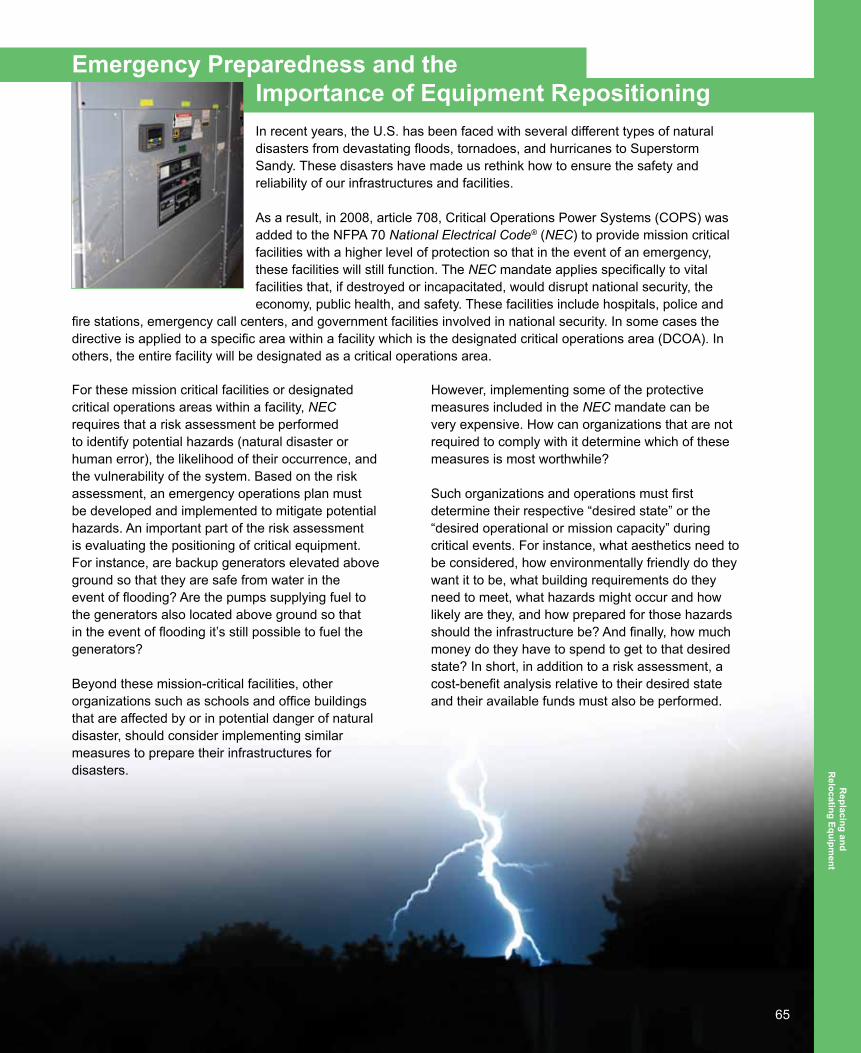
65
Emergency Preparedness and the Importance of Equipment RepositioningIn recent years, the U.S. has been faced with several different types of natural disasters from devastating floods, tornadoes, and hurricanes to Superstorm Sandy. These disasters have made us rethink how to ensure the safety and reliability of our infrastructures and facilities.
As a result, in 2008, article 708, Critical Operations Power Systems (COPS) was added to the NFPA 70 National Electrical Code® (NEC) to provide mission critical facilities with a higher level of protection so that in the event of an emergency, these facilities will still function. The NEC mandate applies specifically to vital facilities that, if destroyed or incapacitated, would disrupt national security, the economy, public health, and safety. These facilities include hospitals, police and
fire stations, emergency call centers, and government facilities involved in national security. In some cases the directive is applied to a specific area within a facility which is the designated critical operations area (DCOA). In others, the entire facility will be designated as a critical operations area.
For these mission critical facilities or designated critical operations areas within a facility, NEC requires that a risk assessment be performed to identify potential hazards (natural disaster or human error), the likelihood of their occurrence, and the vulnerability of the system. Based on the risk assessment, an emergency operations plan must be developed and implemented to mitigate potential hazards. An important part of the risk assessment is evaluating the positioning of critical equipment. For instance, are backup generators elevated above ground so that they are safe from water in the event of flooding? Are the pumps supplying fuel to the generators also located above ground so that in the event of flooding it’s still possible to fuel the generators?
Beyond these mission-critical facilities, other organizations such as schools and office buildings that are affected by or in potential danger of natural disaster, should consider implementing similar measures to prepare their infrastructures for disasters.
However, implementing some of the protective measures included in the NEC mandate can be very expensive. How can organizations that are not required to comply with it determine which of these measures is most worthwhile?
Such organizations and operations must first determine their respective “desired state” or the “desired operational or mission capacity” during critical events. For instance, what aesthetics need to be considered, how environmentally friendly do they want it to be, what building requirements do they need to meet, what hazards might occur and how likely are they, and how prepared for those hazards should the infrastructure be? And finally, how much money do they have to spend to get to that desired state? In short, in addition to a risk assessment, a cost-benefit analysis relative to their desired state and their available funds must also be performed.
Replacing and
Relocating Equipm
ent

66
The factors a facility’s management has to consider in order to determine their maximum effective reliability needs will vary depending on the type of facility, what equipment is critical to desired operations, and where the equipment will be located. For example, a sewer plant is typically located near a body of water, so it is subject to flooding. As a result, when weighing potential risks and the cost of preparing for those risks, a facility manager will likely want to focus on positioning his power and emergency systems on higher ground to prevent damage and possible power interruptions from flooding. Other types of facilities, such as data centers or hospitals, will have different risks to consider when determining reliability needs and preparing for certain risks.
During Superstorm Sandy, a facility in New York City was inundated with water—in some locations the water and sewage in the basement was up to six feet deep. When the storm caused the facility’s power to go out, it switched to generators which were located above potential flood levels. The fuel pumps responsible for fueling the generators, however, were located in the basement which was underwater. As a result, the generators failed and the facility was not operational.
Following the storm, the facility began its restoration process and the steps to better prepare for the next storm. With funding to restore the facility, including damaged electrical equipment, management decided to reposition equipment in order to prevent it from damage in the event of a future storm. The facility’s management installed new equipment in new electrical rooms on the first floor.
While deciding where to reposition certain pieces of equipment, the facility’s management took several factors into consideration including cost, emergency preparedness, and future maintenance of the equipment to be relocated. For instance, to ensure ease of maintenance in the future, the contractor built in the ability to have generator backup easily implemented by adding dual main services to all of the replacement switchboards. In addition, all main and tie circuit breakers were specified to be a “draw out” type in order to facilitate an enhanced preventative maintenance program. This type of circuit breaker is easier to maintain and service than the older style (power switched with fuses).
Such discussions and actions following Superstorm Sandy are good examples of how facilities can look to not just recover, but recover in a way that makes infrastructure more robust and reliable. Many facilities could learn from such examples and prepare for future disasters or events by thinking strategically and investing in a comprehensive reliability assessment. An important part of that reliability assessment will consider the positioning of a facility’s equipment and identify what equipment is most important to protect.
A reliability assessment will enable facility managers to think beyond getting the power equipment back up and running. It can lead to longer term considerations such as the reliability of the power distribution system and all utilization equipment, including HVAC, pumping, and communication systems supported by power equipment. Facility managers must consider the reliability of power and critical equipment relevant to environmental factors, as well as possible external threats and how to function and maintain the appropriate and necessary levels of reliability.

67
Once key power and utilization equipment has been identified, facility management can consider how to position equipment to increase reliable electrical power and operations during future emergencies or disasters. Natural disasters will continue to occur; there will be an increasingly important process for all types of organizations to follow in order to prepare their infrastructures to weather these storms. Responsible organizations recognize that recovery from Superstorm Sandy isn’t just about getting back up and running; it’s about rebuilding smarter to lessen the impact of future events. Relocating or Repositioning of Equipment
Relocating transmission infrastructure is not feasible, however, stringing higher voltage lines and incorporating Smart Grid or sensory equipment will help identify and isolate problems faster, which allows utilities to expedite recovery.
Substation equipment is manufactured to meet standards, such as those developed by NEMA and the American National Standards Institute, and will perform in a wet environment, but cannot be submerged. The key is keeping the energized parts separated from the non-energized parts. The substation needs to be protected from floodwaters either by barriers or built high enough to withstand storm surge.
As a rule, higher voltage switches are mounted 10 feet off of the ground, allowing switch operation if the station is still energized. Breakers, transformers, and metering inside the switch houses are also susceptible to flood damage. Utilities should consider if it is more cost effective to build substations to withstand severe events or build them so they can be repaired or reenergized quickly. Taking distribution of power from overhead to underground is relevant for areas not prone to storm surge.
While it is costly to build underground infrastructure, it does eliminate the added costs for replacing poles, anchors, and hardware. Underground infrastructure is more resilient to high-wind conditions. The tradeoff is higher maintenance and repair costs.
In areas where underground location is not a viable solution, more switching points, and in some areas, auto-restoration, can be added. This segments the system into more manageable sections, isolating damage and allowing service to be restored more quickly to smaller areas, rather than waiting until much larger areas are repaired. Roadmap Recommendations
It is important that when implementing any recommendations for system hardening or storm preparation that there is a direct correlation between average repair costs due to storms versus the investment of building or relocating new infrastructure.
■■ Create a national standard for equipment and structures in vulnerable areas. Although there are standards that equipment and structures must meet to carry certain voltage levels, there isn’t a national rating standard for equipment in areas highly susceptible to storm damage. Products in these areas should be required to meet higher wind and flood standards to minimize outages and destruction to other equipment. Standards should also include the frequency in which products and poles/structures are inspected for damage or corrosion.
68
■■ Work with other organizations and government offices to create a unified emergency storm response plan. If access to roads is obstructed, linemen and other emergency responders can’t repair the damage to power lines. Therefore, it’s necessary to communicate with appropriate departments to ensure that there is a cohesive plan in place for natural disasters, accounting for damaged or fallen communication lines.
■■ Determine the cost effectiveness of implementing changes to infrastructure. In areas that see little or infrequent storm damage, it is not cost effective to implement the same measures as in coastal or other vulnerable areas. The cost to end-users to implement these changes can be vast. A simple comparison of recent storm damage costs versus the investment to upgrade equipment will help determine the areas of focus for repositioning equipment.
■■ Work to harden systems and reposition equipment. After the areas of most vulnerability are determined, consider all viable options to strengthen and reposition the existing equipment to better withstand damaging winds, floods, and ice. Consider elevating equipment above the 10-foot standard in areas susceptible to floods and areas below sea level. Reconfigure equipment on poles to better withstand large gusts of wind. When replacing poles, consider using ones larger in diameter that will have better resistance to wind. In areas with minimal flood damage, consider moving equipment and lines underground to prevent wind and ice damage to lines.

69
Replacing or Upgrading Water-Damaged Electrical Equipment NEMA’s Evaluating Water-Damaged Electrical Equipment19, first published in 2004, contains excellent reference material to evaluate electrical equipment that has been exposed to water through flooding, firefighting activities, hurricanes, and other circumstances.
The document provides a table summarizing recommended actions for various types of electrical equipment to determine whether they need to be replaced or reconditioned. New technological solutions have been developed that provide a third option: the core device (e.g., power circuit breaker, motor control center enclosure) is replaced with an upgraded device that matches the original
equipment’s mechanical and electrical interfaces. The upgraded device is consistent with new equipment standards and technological advancements without disturbing the primary enclosure, incoming and outgoing cable connections, or operating controls.
The benefits of upgrading versus the traditional replacement option are:
■■ Costs for direct replacement upgrade devices are equal to or less than replacement equipment of the original design. The cost advantage is derived by the use of available manufactured components and devices versus tooling required to manufacture equipment which may have been in service for ten to twenty years or longer.
■■ Delivery is faster since the direct replacement devices are in-stock and the mechanical and electrical interfaces have been designed and stocked for common vintage equipment.
■■ New technology can be incorporated within existing structures at no added costs. Additional safety features can also be included to better address arc-flash concerns and personnel safety.
______________________________19 Evaluating Water-Damaged Electrical Equipment, National Electrical Manufacturers Association (NEMA), 2004
(www.nema.org/Standards/Pages/Evaluating-Water-Damaged-Electrical-Equipment.aspx)
■■ Speed of remediation is greatly increased since complete removal of the entire electrical structure is not required, cables are not disturbed, and equipment upgrades can be completed in intervals—allowing for selected power restoration during the remediation process. For power circuit breakers or motor control centers, individual devices can be installed as remediation progresses.
■■ Long-term reliability is improved by adding optional system improvements during the remediation period and includes monitoring of predictive failure modes such as: humidity, temperature, dust, smoke, intrusion, vibration, floor water, power quality, or other parameters. For medium voltage equipment, continuous partial discharge activity can also be monitored. These reliability improvements provide for audible alarms, messaging (text, voice, and email), and also service dispatch, depending on the needs of the customer.

70
■□ NOTE: Water damage from any body of water is usually defined as “flood damage,” therefore an overhead steam or water leak can be defined as flood damage. Being notified of floor water and/or increasing humidity allows for immediate corrective actions, preventing subsequent electrical equipment failure.
■■ Life-extension of existing capital investments is achieved due to the critical core components and devices being replaced with “new” devices.
The following are examples of categories within NEMA’s Evaluating Water-Damaged Electrical Equipment. Included is an upgrade option in addition to the replacement or recondition options. These solutions have been applied for past hurricanes and other flood conditions.
Motor Control Center Equipment
New technology motor control center equipment, commonly referred to as MCC inserts or buckets, can be equipped with mechanical and electrical interfaces to become direct replacements for many manufacturers’ motor control equipment.
Example Scenario
In October 2012, Superstorm Sandy battered the Northeast and many facilities suffered major damage. One major utility company lost an entire line-up of MCCs at one of its power generation facilities. The utility contacted a service group in New Jersey to get an assessment on replacement and upgrade capabilities.
A NEMA member factory was able to supply replacements to the customer within days. Because the factory’s service group provided the installation and start-up, the down time suffered by the utility was dramatically shortened.
Power Equipment
New technology circuit breakers can be encased within a mechanical and electrical interface, including insulating bushing and electrical secondary controls, to provide for direct replacement to many manufacturers’ circuit breaker assemblies. These solutions apply to low voltage power circuit breakers (600V) as well as 5/15kV assemblies. Figure 1 illustrates an example of a low voltage power circuit breaker upgrade solution and Figure 2 illustrates an example of a 4.16kV or 15kV circuit breaker upgrade solution.
Section 4.3 in Evaluating Water-Damaged Electrical Equipment also discusses the potential for reconditioning of protective relays, meters, and transformers. A recommendation suggests contacting the original equipment manufacturer to ensure that all electronic protection and control functions have been fully restored. An upgrade option is also available for these applications since newer multi-function relays and metering can replace multiple traditional devices. The benefits described earlier concerning cost savings, speed of delivery, and improved technology also apply in this application. Figure 3 illustrates an example of an upgrade solution for relays, metering, and controls while maintaining the existing equipment structure.

71
Original LV Circuit BreakerCurrent Manufactured LV Circuit Breaker within Mechanical / Electrical Interface for
Direct Replacement
Figure 1. Power Equipment—480V Circuit Breaker Upgrade Option
Original 15kV Circuit BreakerCurrent Manufactured 15kV Circuit Breaker within Mechanical / Electrical Interface for
Direct Replacement
Figure 2. Power Equipment—5/15kV Circuit Breaker Upgrade Option

72
Original Relays, Metering, and Controls Upgraded Multi-Function Relay, Metering, and Controls
Figure 3. Power Equipment—Protective Relay, Metering, and Controls Upgrade Option
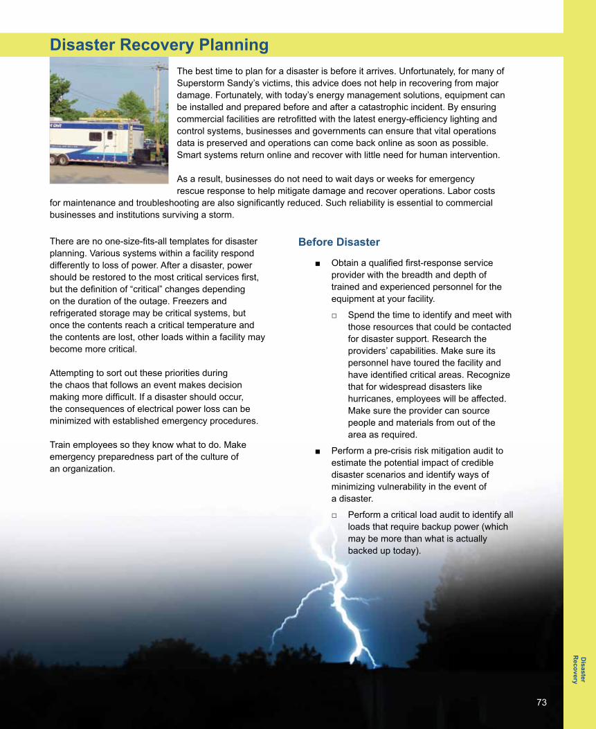
73
Disaster Recovery PlanningThe best time to plan for a disaster is before it arrives. Unfortunately, for many of Superstorm Sandy’s victims, this advice does not help in recovering from major damage. Fortunately, with today’s energy management solutions, equipment can be installed and prepared before and after a catastrophic incident. By ensuring commercial facilities are retrofitted with the latest energy-efficiency lighting and control systems, businesses and governments can ensure that vital operations data is preserved and operations can come back online as soon as possible. Smart systems return online and recover with little need for human intervention.
As a result, businesses do not need to wait days or weeks for emergency rescue response to help mitigate damage and recover operations. Labor costs
for maintenance and troubleshooting are also significantly reduced. Such reliability is essential to commercial businesses and institutions surviving a storm.
There are no one-size-fits-all templates for disaster planning. Various systems within a facility respond differently to loss of power. After a disaster, power should be restored to the most critical services first, but the definition of “critical” changes depending on the duration of the outage. Freezers and refrigerated storage may be critical systems, but once the contents reach a critical temperature and the contents are lost, other loads within a facility may become more critical.
Attempting to sort out these priorities during the chaos that follows an event makes decision making more difficult. If a disaster should occur, the consequences of electrical power loss can be minimized with established emergency procedures.
Train employees so they know what to do. Make emergency preparedness part of the culture of an organization.
Before Disaster
■■ Obtain a qualified first-response service provider with the breadth and depth of trained and experienced personnel for the equipment at your facility.
■□ Spend the time to identify and meet with those resources that could be contacted for disaster support. Research the providers’ capabilities. Make sure its personnel have toured the facility and have identified critical areas. Recognize that for widespread disasters like hurricanes, employees will be affected. Make sure the provider can source people and materials from out of the area as required.
■■ Perform a pre-crisis risk mitigation audit to estimate the potential impact of credible disaster scenarios and identify ways of minimizing vulnerability in the event of a disaster.
■□ Perform a critical load audit to identify all loads that require backup power (which may be more than what is actually backed up today).
Disaster
Recovery

74
■□ Identify consequences of potential natural (e.g., flood, tornado, hurricane, earthquake) and man-made (e.g., terrorist, human error within organization) threats. This analysis should take into account physical surroundings (e.g., proximity to rail, airports, ship ports, or highways) and includes financial impact resulting from the loss of that equipment.
■□ Outline consequences of electricity loss (e.g., computer failure, loss of access, contamination, trapped persons, chemical release, etc.) with varying durations of outage. Have a contingency plan to deal with each consequence (e.g., manual key entry backup to electronic locks). Note: Pre-crisis audits provide the additional benefit of potentially identifying internal problems—remember, not all problems are caused by external events—that could cause several issues including: storage blocking equipment access/escape routes, missing breaker racking or lifting tools, missing drawings, etc.
■■ Conduct a safety audit and establish procedures to assure injury free remediation.
■■ Assure regulatory compliance awareness
■■ Identify all critical documentation and create a plan to store this information so that it can be accessed off-site in one or more safe locations. Do not assume that cloud communications will be available in all disaster scenarios.
■■ Consider adding local electrical power generation. This can take the form of:
■□ Permanent onsite local generation is high cost, but eliminates the need to rely on a rental company having a generator when you need it. However, this increases responsibility to ensure the system is functioning. A common solution is to contract out maintenance to a qualified engine dealer, typically the seller. Don’t forget to contract with fuel providers for fuel delivery since normal fuel delivery will likely be affected after a problem that strikes a wide area.
■□ Add provisions for temporary power hook up. Opening and working on electrical equipment can only be done by trained, certified professionals, and this includes connecting an emergency generator. Remember, during times of emergency, trades people will be in high demand and short supply as the hard work of restoring power begins. Consider having provisions already installed to allow simply plugging-in a backup generator.
■□ Alternative energy sources, such as a solar energy system, are typically designed to operate when utility grid power is available and automatically shut down when utility power is lost; however, in times of emergency, having electrical power is highly desirable. Meet with a solar installation provider or a qualified engineering service provider to explore ways of configuring local alternative energy sources into an “island” or a microgrid on an as-needed basis. This may involve adding additional protective devices or devices to automatically shed lower priority loads since alternative energy is rarely sized to power an entire building’s load.

75
■■ Identify sources of equipment repair and replacement. These sources should be certified for the equipment installed. Since many facilities are older and may include electrical equipment from a variety of electrical vendors, look for sources that have the certification or other demonstrated proficiency to repair, renovate, and renew the electrical equipment installed at your facility.
■■ Make sure contracted support organizations have expertise in staging of support equipment including generators, replacement electrical equipment, and satellite communication networks.
■■ Develop a plan for living and support accommodations for an in-house crisis response team, and ensure that contracted support teams are similarly prepared. Food, water, and sleeping accommodations may be in short supply so make sure support teams can support themselves.
■■ With a radio communication system, ensure its operability following an electrical system failure. Typically this involves supplying power to chargers and repeaters.
■■ Document your equipment installed (brand, model, serial), device settings, and software (vendor provided and user purchased). Update documentation when you buy or change equipment or settings. Make sure new staff members are trained on this procedure as previous staff leave. Have clear responsibilities as to who is responsible to keep the data updated.
Recovering after Disaster
■■ Depending on how widespread the disaster, recognize that failure of communication systems may prevent contacting service providers. Consider prearranging with those providers to check-in following a wide area event.
■■ Execute disaster recovery plan. Mobilize disaster recovery team, each with assigned tasks.
■□ Team will include internal company personnel and external contractors.
■□ Use established team leaders to prioritize tasks. Consider outsourcing project management for specialty items such as electrical equipment repair or restoration.
■■ Flood waters conduct electricity. Entering a flooded building, especially rooms containing electrical equipment, is dangerous. Only trained personnel skilled in operating in this environment should enter such a facility.
■■ Whether or not you have done any preplanning, once a disaster hits, don’t panic. Choose electrical service providers carefully. While qualified service personnel may be in short supply following a wide area disaster, be careful in your rush to find support. Hire only qualified service providers. Several manufacturers of electrical equipment have programs where electrical service providers are certified by the manufacturer. Review their recommendations by visiting manufacturers’ websites. A listing of electrical equipment manufacturers is available at www.nema.org/mfgs.

76
■■ Once you have recovered from a disaster, spend time reviewing what worked, what didn’t, and what could have been done differently or prevented. Update your plan as equipment is bought, upgraded, changed, or repaired.
Example
Hurricane Rita, one of the most intense Atlantic hurricanes recorded, struck Lake Charles, Louisiana, on September 24, 2005. A chemical manufacturing plant in Lake Charles found itself in dire circumstances as Hurricane Rita left the facility without power at a critical point in its production cycle. Several million dollars of process materials and equipment were at risk and would result in a total loss within one week without restoration of power. By using an outside team skilled in this type of emergency recovery, the equipment was saved and shipping deadlines met.
Roadmap Recommendations
■■ Develop relationship with a proven service supplier.
■■ Review and understand critical power points within the operation.
■■ Analyze opportunities for alternative power and backup generation for critical power loads.
■■ Evaluate the energy management system that is right for your facility. Lighting and energy solutions companies can evaluate the size of the facility, nature of business and operations, disaster threats (e.g., earthquakes or flooding), and other considerations to recommend and quote newer, smarter technologies suited to specific needs.
■■ When a new system is installed, ensure it is properly programmed for emergencies. If possible, connect the system to the building automation system emergency protocols. Run diagnostic tests to ensure that lighting and data recovers in the event of emergencies.
■■ If you have experienced storm damage, explore retrofit options. For example, energy-harvesting wireless solutions are ideal for replacing and retrofitting damaged buildings. They can be placed and programmed in minutes, and do not require pulling wires. As a result, essential business functions can continue uninterrupted, expediting recovery.
■■ Investigate upgrades for existing systems. If you have already invested in a distributed control or centralized control system, investigate what options are available to upgrade to newer, smarter technologies with reliable recovery and constant data preservation. These improved technologies are safer with higher voltage ratings, and much speedier, smoother recovery times after power interruptions.
Reference
Evaluating Water-Damaged Electrical Equipment National Electrical Manufacturers Association (NEMA)
■■ www.nema.org/Standards/Pages/Evaluating-Water-Damaged-Electrical-Equipment.aspx
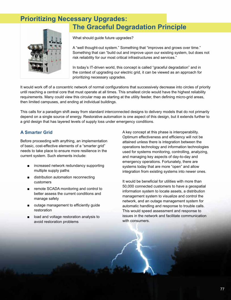
77
Prioritizing Necessary Upgrades: The Graceful Degradation Principle What should guide future upgrades?
A “well thought-out system.” Something that “improves and grows over time.” Something that can “build out and improve upon our existing system, but does not risk reliability for our most critical infrastructures and services.”
In today’s IT-driven world, this concept is called “graceful degradation” and in the context of upgrading our electric grid, it can be viewed as an approach for prioritizing necessary upgrades.
It would work off of a concentric network of normal configurations that successively decrease into circles of priority until reaching a central core that must operate at all times. This smallest circle would have the highest reliability requirements. Many could view this circular map as starting at the utility feeder, then defining micro-grid areas, then limited campuses, and ending at individual buildings.
This calls for a paradigm shift away from standard interconnected designs to delivery models that do not primarily depend on a single source of energy. Restorative automation is one aspect of this design, but it extends further to a grid design that has layered levels of supply loss under emergency conditions.
A Smarter Grid
Before proceeding with anything, an implementation of basic, cost-effective elements of a “smarter grid” needs to take place to ensure more resilience in the current system. Such elements include:
■■ increased network redundancy supporting multiple supply paths
■■ distribution automation reconnecting customers
■■ remote SCADA monitoring and control to better assess the current conditions and manage safety
■■ outage management to efficiently guide restoration
■■ load and voltage restoration analysis to avoid restoration problems
A key concept at this phase is interoperability. Optimum effectiveness and efficiency will not be attained unless there is integration between the operations technology and information technologies used for systems monitoring, controlling, analyzing, and managing key aspects of day-to-day and emergency operations. Fortunately, there are systems today that are more “open” and allow integration from existing systems into newer ones.
It would be beneficial for utilities with more than 50,000 connected customers to have a geospatial information system to locate assets, a distribution management system to visualize and control the network, and an outage management system for automatic handling and response to trouble calls. This would speed assessment and response to issues in the network and facilitate communication with consumers.
78
Infrastructure: Working Toward Self-sustaining Electrical Islands
Maintaining critical infrastructure such as hospitals, prisons, police and fire stations, and street lights requires more than just backup generation for isolated buildings or systems; it requires self-sustaining power infrastructures such as embedded microgrids. Essentially, in a major storm or event, the availability of electric service should “degrade gracefully” into self-sustained areas according to layered priorities assigned to different load areas.
Local generation and storage allow sections of the power grid to operate independently in an intentional island mode during a major grid disturbance, such as the recent widespread outages caused by Superstorm Sandy. Efficiency is increased by locating generation close to the consumption which reduces costs and losses associated with transmission.
A microgrid will utilize distributed energy resources (power generation) throughout its system to provide power when disconnected from the main grid. This typically includes a combination of thermal generation and renewable generation. Importantly, the microgrid can be scaled for different applications and implemented at military bases, critical care facilities, hospital complexes, assisted care campuses, and other designated high priority areas or cells, which essentially aggregate and coordinate load and supply in a defined area. When implementing these microgrids, designs should include important modernizing technologies including alternative generation sources, grid stabilization equipment, grid management software, energy storage, and a communications network.
New microgrids will utilize multiple renewable and alternative fuel generation sources (wind, solar, fuel cells, and natural gas) that can provide power to multiple loads. These alternative power sources will not only allow redundancy, but also reduce dependency on fossil fuel generation.
Gas Insulated Switchgear: Protecting Power Sources from Water
Medium-voltage (MV) switchgear, especially for electrical substations, is available in gas-insulated form. Gas-insulated switchgear (GIS) is contained in a fully sealed vessel, which means that all electrical conductors and vacuum interrupters are protected from the environment. This type of containment makes MV switchgear conductors resistant to water contamination. Furthermore, the insulated cables that connect the GIS use a type of connector that is resistant to temporary submersion. While GIS is not normally designed to be operated in a submerged condition, it is likely that it would withstand a major interruption if temporarily immersed in water.
Reliability Enabled with Communications Capabilities
Today’s advanced reliability improvement technologies offer advanced protection for overhead radial lines. They are capable of almost completely removing the impacts of temporary fault currents on radial lines and when applied with unique fault-clearing speed (one-half cycle), it can also protect the fuse in the case of temporary faults. This technology is usually designed to be installed in a series to the fuse. When it senses a fault current, it will open and stay open for a pre-determined time (dead time). Then it will close again and remain closed. If the fault is temporary, then the radial line is re-energized. If the fault is permanent, then the fuse will blow, protecting the system.
79
In order to minimize installation and operating costs, this technology is often offered as part of an integrated system of tools and accessories. One of the most important of these is the communications module which allows the crew to interface with the technology from ground level using a laptop or handheld device. All of the different system components, when working together, permit easy installation, fast commissioning, and reliable operation in all conditions.
Feeder Distribution Systems Locate, Isolate, and Restore
To be most effective immediately, today’s distribution automation solutions should be instantly implementable with a focus on being model-based according to existing national standards, including those of the Department of Energy and the National Institute of Standards and Technology.
Automation controllers should easily mount in new or existing reclosers, switches, and substation circuit breakers. The purpose of these automation controllers is to detect and locate faults in the feeder circuit, isolate the faulted section, then restore power to the unfaulted sections up to the rated capacity of the alternate power source. Sensing is provided via current transformer and potential informer inputs. Automation controllers can be installed inside any manufacturers’ switchgear and can be configured to work with the feeder’s existing protection logic.
Quicker Restoration: Reliable Power via Modular Energy Storage
The power distribution market is shifting. Today’s increasing utilization of distributed generation and renewables leads to new challenges which result from the unpredictable generation capacity of renewable energy, especially during unforeseeable outages.
Modular energy storage systems are a viable solution for a sustainable and reliable supply of power in the future, whether for the integration of fluctuating renewable energy sources in the grid, self-sufficient power for microgrids, or as reliable reserve during outages.
These systems combine cutting-edge power electronics for grid applications and the latest high-performance lithium-ion batteries. Importantly, their modular design enables power and capacity to be adapted to specific demands and ensures high availability and reliability.
Roadmap Recommendations
■■ Make existing grid smarter with easily implementable, open, drop-in technologies that allow a graceful degradation of the entire system.
■■ Enhance critical infrastructure sites with protected, self-sustaining islands of power in the form of embedded microgrids.
■■ Improve the resiliency, notification, and restoration time for less critical areas with drop-in, flexible, expandable solutions that allow future integration into a broader, smarter system.

80
Index
AAdvanced distribution automation 7, 19Advanced metering infrastructure 15, 23
BBackup power 7, 9, 39, 40, 41, 46, 47, 48, 49, 50,
73Backup Power 4, 38, 47Batteries 14, 34, 37, 38, 45, 49, 50, 79Battery 8, 9, 37, 38, 39, 40, 41, 46
CCable 10, 55, 56, 57, 58, 63, 69Cable 4, 55, 56Cables 10, 55, 56, 57, 58, 69, 78Cogeneration 5, 9, 31, 32, 42, 43Combined heat and power 5, 8, 9, 32, 34, 38, 42Combined Heat and Power 3, 38, 42Cyberattack 6, 8, 25, 28, 40Cyberattacks 7, 40Cybersecurity 28, 33, 41
DDemand response 6, 14, 38Distributed generation 31, 79Distributed Generation 7Distribution automation 7, 17, 19, 21, 26, 61, 77, 79Distribution automation 6Distribution management system 25, 77Distribution management systems 6, 18, 20
EEnergy management system 60Energy storage 5, 7, 8, 9, 32, 34, 37, 38, 39, 40, 41,
46, 78, 79Energy Storage 3, 7, 31, 37, 38, 39, 40, 41Evaluating Water-Damaged Electrical Equipment
69, 70, 76
FFault location, isolation, and restoration 40Fault location, isolation, and service restoration 7,
24
GGenerators 8, 9, 10, 11, 32, 33, 34, 35, 38, 40, 42,
45, 49, 51, 52, 65, 66, 75Geographic information system 25
IIntegrated distribution management systems 6, 18Intelligent electronic devices 24
LLEDs 45, 46
MMicrogrid 7, 8, 9, 31, 32, 33, 34, 35, 36, 38, 41, 46,
74, 78Microgrid 7, 8, 34, 35
NNational Electrical Code® 11, 55, 65National Electrical Manufacturers Association 5, 69,
76
81
OOutage management system 7, 15, 24, 77
PPhase angle monitoring 60Phasor measurement units 60Power oscillation monitoring 60
RReclosers 7, 17, 19, 20, 25, 53, 79Renewable energy 32, 40, 79
SSafety 6, 9, 11, 16, 22, 26, 28, 31, 35, 37, 38, 46,
47, 48, 65, 69, 74, 77SCADA 20, 24, 25, 26, 27, 63Smart Grid 3, 6, 7, 13, 18, 19, 20, 22, 38, 60, 61,
67Smart meters 6, 13, 14, 15, 16, 17, 19, 60Smart meters 6, 13, 14, 15, 16, 17Smart Meters 3, 13, 15Superstorm Sandy 5, 18, 23, 31, 33, 37, 40, 42, 43,
45, 48, 51, 55, 59, 62, 65, 66, 67, 70, 73, 78Switchgear 10, 56, 62, 63, 78, 79
TTransmission and distribution 18, 32, 51, 56, 60Trusted platform module 29
UUninterrupted power supplies 37
VVAR 23, 60Voltage stability 34, 36, 43, 60Volt/VAR 19
WWater-Damaged Electrical Equipment 4, 69, 70, 76Wire 10, 55, 58, 61

The Association of Electrical and Medical Imaging Equipment Manufacturers1300 North 17th Street, Suite 1752, Rosslyn, VA 22209 703.841.3200 • www.NEMA.org/Storm-Reconstruction
®
CONTRIBUTORS


