Engineering for Humans: A New Extension to STPA
by
MEGAN ELIZABETH FRANCE
B.S. Human Factors Engineering, Tufts University, 2015
Submitted to the Department of Aeronautics and Astronautics
in partial fulfillment of the requirements for the degree of
MASTER OF SCIENCE IN AERONAUTICS AND ASTRONAUTICS
at the
MASSACHUSETTS INSTITUTE OF TECHNOLOGY
June 2017
© 2017 Megan France. All Rights reserved.
The author hereby grants to MIT permission to reproduce and to
distribute publicly paper and electronic copies of this thesis document
in whole or in part in any medium now known or hereafter created.
Signature of Author________________________________________________________
Megan E. France
Department of Aeronautics and Astronautics
25 May, 2017
Certified by ______________________________________________________________
Nancy G. Leveson, Ph.D., Professor
Department of Aeronautics and Astronautics
Thesis Supervisor
Accepted by _____________________________________________________________
Youssef M. Marzouk, Ph.D., Associate Professor
Department of Aeronautics and Astronautics
Graduate Committee Chair
v
Engineering for Humans: A New Extension to STPA by
Megan Elizabeth France
Submitted to the Department of Aeronautics and Astronautics on
May 25, 2017 in partial fulfillment of the requirements for the degree of
Master of Science in Aeronautics and Astronautics
Abstract
From space shuttles to airplanes to everyday automobiles, today’s systems are
increasingly complex—and increasingly connected. In order to ensure that increased
complexity does not simply bring an increased number of accidents, this new complexity
demands new safety analysis tools.
Systems-Theoretic Accident Model and Processes (STAMP) is a new accident
causality model developed by Nancy Leveson at the Massachusetts Institute of
Technology. This model has inspired several new methods, from accident analyses like
Causal Analysis based on STAMP (CAST) to hazard analyses like Systems-Theoretic
Process Analysis (STPA). Unlike traditional methods, which are based on chain-of-events
causality models and generally identify only component failures, STPA can be used to
identify design flaws, component interactions, and human factors that contribute to
accidents. Though STPA takes a more thoughtful approach to human error than traditional
methods—requiring analysts to consider how system conditions may lead to “errors”—it
does not provide extensive guidance for understanding why humans behave the way they
do. Prior efforts have been made to add such guidance to STPA, but there has yet to emerge
a widely accepted, easy-to-use method for examining human behavior using STPA.
The goal of this work is to propose a new method for examining the role of humans
in complex automated systems using STPA. This method, called STPA-Engineering for
Humans, provides guidance for identifying causal scenarios related to interactions between
humans and automation and understanding why unsafe behaviors may appear appropriate
in the operational context. The Engineering for Humans method integrates prior research
on STPA and human factors into a new model intended for industry applications.
Importantly, this model provides a framework for dialogue between human factors experts
and other engineers. In this thesis, the Engineering for Humans method is applied to a
case study of an automated driving system called Automated Parking Assist. Four different
implementations of this system at different levels of automation are examined. Finally, it
is demonstrated that STPA-Engineering for Humans can be used to compare how multiple
system designs would affect the safety of the system with respect to the behavior of the
human operator.
Thesis Supervisor: Nancy G. Leveson
Title: Professor of Aeronautics and Astronautics
Keywords: STAMP, STPA, Human Factors, Automation, Automated Cars
vii
Acknowledgments
I would like to thank Dr. Nancy Leveson for inviting me to join her research group and contribute to the
incredible impact that STAMP and STPA have had on safety. I would also like to thank Dr. John Thomas for
his guidance and feedback throughout this process, and for the initial suggestion of the new human controller
model.
Special thanks to General Motors for their sponsorship of this research project and their enthusiastic adoption
of the STPA Engineering for Humans extension.
Lastly, I would like to thank all those who have helped me along the way, including my friends and family,
my classmates and professors from both Tufts and MIT, and all of my colleagues at the Volpe National
Transportation Systems Center and Liberty Mutual Research Institute for Safety.
Thank you all so much for your support and encouragement!
ix
Contents
Abstract v
Acknowledgments vii
List of Tables xiii
List of Figures xv
List of Abbreviations xvii
1. Introduction 1
1.1 Research Purpose .................................................................................................1
1.2 Objectives .............................................................................................................1
1.3 Thesis Structure ....................................................................................................2
2. Literature Review 3
2.1 Traditional Approaches to Safety .........................................................................3
2.1.1 The Old View of Human Error ...............................................................3
2.1.2 Chain-of-Events Accident Causality Models ..........................................4
2.1.3 Traditional Accident and Hazard Analysis Methods ..............................5
2.2 New Perspectives on Safety and Human Error ....................................................6
2.2.1 The New View of Human Error ..............................................................6
2.2.2 Systems-Theoretic Accident Model and Processes (STAMP) ...............6
2.2.2.1 System-Level Accidents .........................................................7
2.2.2.2 System-Level Hazards ............................................................8
2.2.2.3 Safety Control Structure .........................................................8
2.2.3 Systems Theoretic Process Analysis (STPA) .........................................9
2.2.3.1 Writing Unsafe Control Actions ..........................................10
2.2.3.2 Identifying Causal Scenarios ................................................11
2.2.3.3 STPA Models of the Human Controller ...............................12
2.3 Human Factors ...................................................................................................14
x Contents
2.3.1 Models of Human Information Processing ...........................................14
2.3.1.1 Rasmussen’ Skill-Rule-Knowledge model ..........................15
2.3.1.2 Wickens’ Human Information-Processing Model ................16
2.3.1.3 Three Stage Information Processing Model .........................17
2.3.1.4 Endsley’s Model of Situation Awareness ............................18
2.3.2 Decision Making Theories ....................................................................19
2.3.3 Understanding Human-Automation Interaction ....................................21
2.3.3.1 Task Allocation ....................................................................21
2.3.3.2 Supervisory Control and Levels of Automation ..................22
2.3.3.3 Limitations of Automation ...................................................24
2.3.4 Developing a Human Factors Extension for STPA ..............................26
3. STPA - Engineering for Humans 27
3.1 A New Model for Human Controllers ................................................................28
3.2 A New Method for Identifying Causal Scenarios ..............................................29
3.2.1 Control Action Selection .......................................................................29
3.2.2 Mental Models ......................................................................................31
3.2.2.1 Mental Model of Process State .............................................32
3.2.2.2 Mental Model of Process Behavior ......................................32
3.2.2.3 Mental Model of Environment .............................................33
3.2.3 Mental Model Updates ..........................................................................34
3.3 Benefits of the Engineering for Humans Extension ...........................................36
4. Application to Automated Parking Assist 39
4.1 System Descriptions ...........................................................................................41
4.1.1 System 1: Driver Assistance .................................................................42
4.1.2 System 2a: Partial Automation .............................................................44
4.1.3 System 2b: Partial Automation .............................................................46
4.1.4 System 3: Conditional Automation .......................................................48
4.1.5 Summary and Comparison of APA Systems ........................................50
4.2 STPA Fundamentals ...........................................................................................51
4.2.1 System Accidents and Hazards .............................................................51
4.3 Using the Engineering for Humans Extension ...................................................52
Continued xi
4.3.1 Unsafe Braking in System 1 ..................................................................53
4.3.2 Unsafe Braking in System 2a ................................................................56
4.3.3 Unsafe Braking in System 2b ................................................................59
4.3.4 Unsafe Braking in System 3 ..................................................................62
4.4 Using STPA to Examine Automation Capabilities ............................................65
4.4.1 Comparison of UCAs Across Systems .................................................65
4.4.2 Effect of Increased Automation on Computer UCAs ...........................66
4.4.3 Effect of Increased Automation on Driver UCAs .................................67
4.4.4 Implications ...........................................................................................68
5. Conclusions 69
5.1 Contributions ......................................................................................................69
5.2 Limitations .........................................................................................................70
5.3 Recommendations and Future Work ..................................................................70
A Unsafe Control Actions 73
System 1: “Driver Assistance”.....................................................................................74
System 2a: “Partial Automation” .................................................................................78
System 2b: “Partial Automation”.................................................................................82
System 3: “Conditional Automation” ..........................................................................86
References 91
xiii
List of Tables
Table 1. The basis for a new foundation for safety engineering; adapted from [14]. ......... 7
Table 2. Example format of an Unsafe Control Action (UCA) table, adapted from [16]. 10
Table 3. Capabilities of four different Automated Parking Assist (APA) computers. ..... 41
Table 4. Comparison of four APA system implementations. ........................................... 50
Table 5. System-level accidents for an automated parking system. ................................. 51
Table 6. System-level hazards and safety constraints for an automated parking system. 52
Table 7. Unsafe control actions related to braking in System 1. ...................................... 53
Table 8. Unsafe control actions related to braking in System 2a...................................... 56
Table 9. Unsafe control actions related to braking in System 2b. .................................... 59
Table 10. Unsafe control actions related to braking in System 3. .................................... 62
Table 11. Number of driver and computer UCAs identified for each APA system. ........ 65
Table 12. Number of common UCAs among four different APA implementations. ....... 66
xv
List of Figures
Figure 1. Domino Accident Model [9]. .............................................................................. 4
Figure 2. Swiss Cheese Model [22]. ................................................................................... 5
Figure 3. General model of a sociotechnical safety control structure [14]. ........................ 9
Figure 4. Example of the four parts of an unsafe control action [26]. .............................. 11
Figure 5. A classification of control flaws that can lead to hazards [14]. ......................... 12
Figure 6. Human Controller Model [14]. .......................................................................... 13
Figure 7. STPA-RC human controller model [16]............................................................ 14
Figure 8. Rasmussen’s Skill-Rule-Knowledge Model, adapted from [20]. ...................... 15
Figure 9. Wickens’ Human Information-Processing Model [31], [34]. ........................... 16
Figure 10. The 4-D Multiple Resource Model [32]. ......................................................... 17
Figure 11. Three-Stage Model of human information-processing [19]. ........................... 17
Figure 12. Endsley's model of situation awareness in dynamic systems [6]. ................... 19
Figure 13. Recognition-Primed Decision Model [11]. ..................................................... 20
Figure 14. Fitts’ "MABA-MABA" list [7]. ...................................................................... 21
Figure 15. The spectrum of control modes [25]. .............................................................. 22
Figure 16. Levels of automation at four information processing stages [18]. .................. 24
Figure 17. Illustration of several possible types of human-automation interaction [25]. . 26
Figure 18. The new Engineering for Humans model. ....................................................... 28
Figure 19. Human controller model in the control loop, adapted from [14]. ................... 29
Figure 20: Benefits of the new human controller model. ................................................. 36
Figure 21: SAE levels of automation [23]. ....................................................................... 40
Figure 22. Safety control structure for System 1. ............................................................. 43
Figure 23. Safety control structure for System 2a. ........................................................... 45
Figure 24. Safety control structure for System 2b. ........................................................... 47
Figure 25. Safety control structure for System 3. ............................................................. 49
Figure 26. Example braking scenario for System 1. ......................................................... 54
Figure 27. Example braking scenario for System 2a. ....................................................... 58
Figure 28. Example braking scenario for System 2b. ....................................................... 61
Figure 29. Example braking scenario for System 3. ......................................................... 64
xvi List of Figures
Figure 30. Number of shared vs. unique APA computer UCAs for each APA system.... 67
Figure 31. Number of shared vs. unique driver UCAs for each APA system. ................. 68
xvii
List of Abbreviations
APA Automated Parking Assist
CAST Causal Analysis based on STAMP
FMEA Failure Mode and Effects Analysis
FTA Fault Tree Analysis
HAZOP Hazard and Operability Analysis
HFACS Human Factors and Analysis Classification Systems
HRA Human Reliability Analysis
RCA Root Cause Analysis
SAE Society of Automotive Engineers
SCM Swiss Cheese Model
SEEV Salience, Effort, Expectancy, Value
STAMP Systems Theoretic Accident Model and Processes
STPA System-Theoretic Process Analysis
UCA Unsafe Control Action
1
Chapter 1
Introduction
1.1 Research Purpose
The number of automated features in today’s vehicles is growing every year. Features such
as blind spot monitoring, backup cameras, automated parking, automated lane keeping, and
adaptive cruise control are increasingly common. With the introduction of each new
feature, the complexity of safety-critical vehicle systems is increased and the potential for
hazardous interactions increases. In modern vehicles, there is therefore an increased need
to understand the interactions between drivers and automation. Rather than attempting to
decide who should be to blame in case of accidents, it is critical to examine why accidents
may occur in the first place and design to prevent them.
Systems Theoretic Process Analysis (STPA) is a new hazard analysis method based
on the Systems Theoretic Accident Model and Processes (STAMP) causality model.
STPA, unlike traditional hazard analyses, addresses not only component failures but also
the role of interactions and multiple causal factors in the unsafe control actions that lead to
accidents. One of the core ideas of STAMP is understanding why unsafe actions may
appear safe in context, a premise that is consistent with new views of human error. These
new views assert that “error” is a product of its environment, and safe behavior can be
promoted through imposing safety constraints on the system.
However, the STPA method does not currently include specific guidance regarding
causes of human behavior. Past extensions have been proposed, but have not been put into
practice on a large scale. Furthermore, these extensions have not been used to explicitly
examine system designs at multiple levels of automation.
Therefore, a new extension to the method is proposed that better addresses the role
of humans within human-machine systems. This extension provides guidance for
identifying causal scenarios related to interactions between humans and automation, and
understanding why unsafe behaviors may appear appropriate in the operational context.
1.2 Objectives
This work had two main objectives.
The first objective was to develop engineering methods and tools to analyze the
role of humans in complex, automated, safety-critical automotive systems. While several
researchers have proposed additional guidance for examining human behavior using
STPA, none have led to the development of an easy-to-use method that is accessible to
engineers and researchers of all backgrounds. The goal of this research was to develop a
method that integrates expertise developed by the human factors and cognitive science
2 Chapter 1
communities, as well as prior work on the STPA human controller model, while remaining
practical for industry applications.
The second objective was to explore the possibility of using STPA to compare
automated system designs in the automotive domain. STPA has been applied to automated
vehicle systems in the past, but most analyses have focused on a single design or
implementation. The automotive industry is interested in classifying levels of automation
and attempting to understand the human factors at each level [23]. This work examines
systems that are classified across several different levels of automation to demonstrate that
STPA can be a useful tool that complements the dialogue already happening in the
automotive industry. The STPA with Engineering for Humans extension is first applied to
several versions of an automated parking assistance feature. Then this thesis addresses how
it can allow designers to compare effects on humans of different system designs.
1.3 Thesis Structure
This chapter, Chapter 1, summarizes the purpose and objectives of this research. Chapters
2 and 3 present a method and the theory on which it is based.
Chapter 2 presents a review of the literature in the system safety and human factors
domains. This chapter begins by addressing differences between systems-based safety
methods and traditional safety methods, then explains the process of applying STPA. The
chapter concludes with a summary of models of human information processing and human-
automation interaction.
Chapter 3 presents a new model of the human controller for use in writing causal
scenarios for STPA. This new model, and the method designed for its use, comprise the
STPA-Engineering for Humans extension. The process of applying the extension, as well
as the benefits of doing so, are explained in this chapter.
Chapter 4 describes an application of the Engineering for Humans extension to an
automated vehicle system, Automated Parking Assist (APA). This chapter explores how
the Engineering for Humans method can be used to examine systems with different
automation designs and draw comparisons between them.
Finally, in Chapter 5, this thesis concludes with suggestions for future research
directions and potential applications of the Engineering for Humans extension.
3
Chapter 2
Literature Review
In order to establish and maintain systems that operate safely, it is necessary to perform
analyses to understand and address causes of accidents. There are many forms that these
analyses may take. They may be proactive, as in the case of hazard analyses designed to
identify potential accidents and prevent them before they occur, or reactive, as in the case
of accident analyses designed to understand what went wrong and how to ensure that the
accident is not repeated.
Furthermore, since there is no system that exists that does not interact with humans
in some capacity, these safety methods must examine the role of humans to thoroughly
understand how accidents can occur. Mindell notes that even “fully autonomous” systems
are still designed, built, and maintained by humans, and generally are designed to perform
some task which is of value to humans [15]. Thus, understanding the role of humans is
important in these contexts as well, though it is often overlooked by traditional analyses.
The following chapter discusses traditional approaches to safety and human error,
including their strengths and shortcomings. It then addresses why systems-based causality
models and analysis techniques may be more effective at improving system safety. This
chapter discusses Systems Theoretic Process Analysis, a systems-based hazard analysis
method, and how it can be used to understand the behavior of human controllers. Finally,
the last section of this chapter reviews prominent models from the Human Factors
literature. These models provide an important foundation for the extension proposed later
in this thesis.
2.1 Traditional Approaches to Safety
The following section describes traditional views of human error and accident causality
models, as well as accident and hazard analysis techniques.
2.1.1 The Old View of Human Error
Dekker [5] describes two views of human error: the “Old View” and the “New View.” This
section describes the old view, which is the one most commonly adopted by traditional
safety approaches.
In the old view of human error, accidents are explained by failures, whether those
failures are mechanical or human. Humans are seen as erratic actors that violate rules and
regulations. After an accident occurs, analysts identify what the humans could have or
should have done to prevent it. Then, operators deemed responsible are fired, punished, or
retrained; rules are tightened; responsibilities are taken away from human operators; and
work proceeds until the next accident when this cycle of blame is repeated.
4 Chapter 2
The old view of human error is based on chain-of-events accident causality model.
2.1.2 Chain-of-Events Accident Causality Models
Any accident or hazard analysis is based on some accident causality model, which is a
theory about how accidents occur. Depending on the underlying accident causality model,
these analyses may identify one or many factors that should be addressed to promote the
safety of the system. Some methods provide quantitative evaluations of risk, while others
provide qualitative explanations.
The accident causality models used in most traditional analyses are called chain of
events models. These models propose that accidents are the result of a sequence of failures
or factors, and can be traced back to some root cause.
Heinrich [9] proposed one of the earliest chain of event models, the Domino
Accident Model, shown in Figure 1. According to this model, the way to prevent accidents
is to remove one of the precipitating events. For example, if an unsafe act is prevented,
there will not be an accident, and if a human error is prevented, there will not be an unsafe
act.
Figure 1. Domino Accident Model [9].
Unfortunately, it is implicit in this model that someone is to blame. Using this type of
causality model, any accident investigation becomes a search for a root cause: “Who is
responsible?” Heinrich does note that people are influenced by social environment, but this
does not free them from blame.
Reason [22] proposed a modern take on the Domino Model (Figure 2) that
incorporates the idea of “defense in depth.” Rather than dominos that must collapse one
after the other, Reason models his barriers as slices of cheese; thus its name, the “Swiss
Cheese Model,” or SCM. Each barrier has certain limitations, whether they be “intrinsic
defects” or vulnerabilities to “atypical conditions.”
STPA - Engineering for Humans 5
The SCM is widely used and accepted due to its simple and intuitive explanation
of accident causation. It seems obvious that any accident could be prevented by simply
adding additional layers of defenses, or patching holes in existing barriers. However, this
model overlooks the possibility of dependence between the barriers; if systemic influences
like company-wide budget cuts can affect the resilience of barriers at multiple levels. It is
not just a matter of “holes lining up” to permit an accident opportunity to arise; subjected
to systemic factors, all the defenses could be affected at once, leaving the system vulnerable
to accidents.
Figure 2. Swiss Cheese Model [22].
2.1.3 Traditional Accident and Hazard Analysis Methods
The majority of traditional hazard analysis methods were designed for electromechanical
systems, and do not address the role of human operators at all. Those that do address the
human operator tend to treat humans simply as a component of the system, and attempt to
calculate or estimate the “reliability” of human behavior.
When analyzing causes of particular accidents, Root Cause Analysis or RCA is the
dominant method. The goal of this method is to understand the cause of the accident so
that future accidents may be prevented. This method relies on a chain of events model, and
suggests that analyst may find the origin of the events that led to the accident and simply
address the originating event. Analysts are often swayed by what Carroll refers to as “Root
Cause Seduction,” the temptation to label a single, easily fixed factor as the root cause [2].
Sadly, this is not how systems work: accidents are almost always the result of many factors
combining in unsafe ways. The factors identified as “root causes” in RCA or other methods
are often only symptoms of a dysfunctional system.
Many traditional hazard analysis techniques are also based on the chain-of-events
model. Leveson [12] summarizes a number of these models. Failure Mode and Effects
Analysis (FMEA) and Fault Tree Analysis (FTA) are bottom-up and top-down techniques
respectively that are used to examine possible sources of accidents within a system. FMEA
aims to identify the likelihood and severity of failures of each component, but does not
examine the possibility of multiple component failures or human errors. FTA shows how
6 Chapter 2
events linked by Boolean logic can lead to accidents. “Human error” may be included in a
fault tree, but it is generally included as a random event rather than an action that could be
explained. Some analyses, such as Human Reliability Analysis (HRA) attempt to quantify
human reliability in systems using data about task performance.
There are other techniques that do not rely on assigning probabilities and instead
classify the types of behavior that lead to the hazardous action, such as Human Factors and
Analysis Classification Systems (HFACS), or Reason’s classification of slips, lapses,
mistakes and violations [22]. Human Factors and Analysis Classification Systems
(HFACS) is an accident analysis based on the Swiss Cheese model that classifies causes
of accidents including underlying organizational factors that lead to unsafe behavior. Other
methods, like Hazard and Operability Analysis (HAZOP) uses guidewords to examine how
accidents may occur in a system. While these classification systems are an important step
toward better understanding humans than traditional probabilistic approaches,
classification of errors is not enough to prevent accidents within a system. For this, we need
a deeper understanding of not only what kind of error may occur, but why it may occur and
how we can prevent it.
2.2 New Perspectives on Safety and Human Error
This section describes new attitudes and techniques for addressing the role of human error
in complex systems.
2.2.1 The New View of Human Error
In Dekker’s “New View” of human error [5], human error is treated as a symptom of
problems, rather than a source of them. Both Leveson [14] and Dekker [5] reject the idea
that human error is random. Leveson argues that there is no value in measuring human
reliability, because humans do not fail at random as electromechanical components do, and
reliability alone is not enough to ensure the safety of a system.
Under Dekker’s new view, human behavior is shaped by a variety of pressures and
goals, and decisions are made based on trading off to attempt to meet multiple, often
conflicting goals. Rather than taking a retrospective view of human error, which is subject
to hindsight bias, Dekker asserts that to improve a system it is necessary to go beyond
labeling “human error” as a cause of accidents and understand why a human might have
done what they did [5].
The following sections discuss new models and methods that take this new view of
human error. These methods aim to understand why unsafe human behavior would appear
reasonable in context so that it may be addressed in the system design and operation.
2.2.2 Systems-Theoretic Accident Model and Processes (STAMP)
System-Theoretic Accident Model and Processes (STAMP) is a new accident causality
model that was developed to include more types of accident causal factors than other
STPA - Engineering for Humans 7
models, including social and organizational structures, design and requirements flaws, and
dysfunctional interactions among non-failed components [13], [14].
Rather than treating safety as a failure problem or simplifying accidents to a linear
chain of events, STAMP treats safety as a control problem in which accidents arise from
complex dynamic processes that may operate concurrently and interact to create unsafe
situations. Accidents can then be prevented by identifying and enforcing constraints on
component interactions.
This model captures accidents due to component failure, but also explains
increasingly common component interaction accidents that occur in complex systems
without any component failures. For example, software can create unsafe situations by
behaving exactly as instructed or operators and automated controllers can individually
perform as intended but together create unexpected or dangerous conditions.
This new model challenges old assumptions about safety. The new assumptions
upon which this model is based are listed in Table 1.
Table 1. The basis for a new foundation for safety engineering; adapted from [14].
New Assumptions about Safety
High reliability is neither necessary nor sufficient for safety.
Accidents are complex processes involving the entire sociotechnical system. Traditional
event-chain models cannot describe this process adequately.
Risk and safety may be best understood and communicated in ways other than
probabilistic risk analysis.
Operator error is a product of the environment in which it occurs. To reduce operator
“error” we must change the environment in which the operator works.
Blame is the enemy of safety. Focus should be on understanding how the system behavior
as a whole contributed to the loss and not on who or what to blame for it.
Several methods for accident and hazard analysis are based on the STAMP model, most
notably Causal Analysis based on STAMP (CAST) for accident analysis and Systems-
Theoretic Process Analysis (STPA) for proactive hazard analysis. The following sections
will describe the core ideas of STAMP and the common steps to any STAMP-based
analysis, then explain the process of applying STPA in greater detail.
2.2.2.1 System-Level Accidents
Unlike chain-of-events models, STAMP is based on systems theory, and treats safety as an
emergent property arising from interactions between system components. According to the
STAMP model, accidents or losses are not always the result of failure events; rather, they
may stem from unsafe interactions among components, external disturbance, or behavior
of individual components that is not failure, but which leads to a hazardous system state
8 Chapter 2
[14]. Accidents can only be prevented by constraining the behavior of the system during
design and operations so that hazardous states do not occur.
Prior to conducting an accident or hazard analysis using methods based on STAMP,
it is necessary to decide on the accidents or losses that must be considered. Typically these
include loss of life or injury, but they may also include financial losses, environmental
damage or other damages that stakeholders wish to prevent.
2.2.2.2 System-Level Hazards
A hazard is defined as “a system state or set of conditions that, together with a particular
set of worst-case environment conditions, will lead to an accident (loss)” [14]. When using
methods based on the STAMP causality model, it is necessary to define a set of high level
hazards that stakeholders are interested in preventing. These hazards are related to the
system accidents defined in the previous step. Each of these hazards can then be reframed
as a system safety constraint that must be enforced to maintain system safety.
2.2.2.3 Safety Control Structure
Because STAMP is based on systems theory, it inherits the view of systems as hierarchical
structures. In such systems, each level constrains the level beneath it; if such constraints
are missing or inadequately communicated, unsafe behavior may occur at lower levels of
the control hierarchy.
Between levels of the hierarchy, there must be both downward control actions, such
as goals, policies, constraints, and commands, and upward feedback channels summarizing
the operational experience at lower levels of the system [14]. Figure 3 shows the general
form of a hierarchical control structure.
STPA - Engineering for Humans 9
Figure 3. General model of a sociotechnical safety control structure [14].
2.2.3 Systems Theoretic Process Analysis (STPA)
STPA is a hazard analysis technique based on the STAMP accident causality model [14].
It differs from traditional hazard analysis techniques (including Fault Tree Analysis, Event
Tree Analysis, and HAZOP) by using a systems-theoretic causality model, rather than a
chain-of-events causality model including a broader range of factors that contribute to
accidents. STPA is capable of identifying not only component failures, but also “design
errors, including software flaws; component interaction accidents; cognitively complex
human decision-making errors, and social, organizational, and management factors
contributing to accidents” [14].
To begin STPA, an analyst must identify the goals of the analysis, by first
determining what kinds of accidents they wish to prevent and defining the hazardous states
that could lead to those accidents. These definitions set the scope of the analysis. Then,
they may identify high-level safety constraints for the system. It is also necessary to build
a model of the safety control structure for the system and to understand the roles and
10 Chapter 2
responsibilities of controllers at each level, as well as the control actions they perform,
feedback they receive, and the process model needed to perform their tasks safely.
The two main steps of the STPA analysis build upon these foundations to identify
possible causes of accidents. First, the analyst identifies “unsafe control actions,” or actions
that could lead to a hazardous state by violating the system safety constraints. Then the
analyst must consider possible explanations for why each unsafe control action may occur.
These explanations are referred to as causal scenarios, and go beyond a simple root cause
analysis: causal scenarios include factors throughout the system that contribute to unsafe
behaviors.
The following sections describe the process of identifying unsafe control actions
and causal scenarios in STPA.
2.2.3.1 Writing Unsafe Control Actions
An unsafe control action (UCA) is simply an action that may lead to a hazard in a given
context. For each control action in the safety control structure, four types of unsafe control
actions can be identified:
• A control action required for safety is not provided
• An unsafe control action is provided that leads to a hazard
• A potentially safe control action provided too late, too early, or out of sequence
• A safe control action is stopped too soon or applied too long (for a continuous or
non-discrete control action)
Typically, UCAs are presented in table format as shown in Table 2 with each of these four
types in a separate column and each control action in a separate row. There may be more
than one UCA in each cell.
Table 2. Example format of an Unsafe Control Action (UCA) table, adapted from [16].
Control
Action
Unsafe Control Actions
Not Providing
Causes
Hazard
Providing
Causes
Hazard
Wrong
Timing
/Order
Duration Too
Short/Long
A Controller does
not provide
“A” when…
context(s)
which lead to
[Hazard(s)]
Controller
provides “A”
when…
context(s)
which lead to
[Hazard(s)]
Controller
provides “A”
too early / too
late when…
context(s)
which lead to
[Hazard(s)]
Controller
provides “A”
too long / too
short when…
context(s)
which lead to
[Hazard(s)]
B … … … …
STPA - Engineering for Humans 11
Thomas [26] notes that each unsafe control action has four key components, as illustrated
in Figure 4. The controller is the entity that can provide the control action. Type refers to
which of the four types or columns the action belongs to: provided, not provided, etc.
Control action refers to the action itself, or the link in the control structure that was
affected. Finally, context describes the conditions under which the action leads to a hazard.
Note that for some UCAs, like UCA 1 in Figure 4, the type is written explicitly, but
when the type is "providing action causes hazard," as in the case of UCA 2, the type is
often not explicitly written.
Figure 4. Example of the four parts of an unsafe control action [26].
It is also convention to identify the possible hazardous outcomes of each UCA by
referencing the relevant hazards after the UCA statement. This provides traceability that
can be carried throughout the analysis. Later, designers and engineers may want to mitigate
the most serious hazards first, and can look to the UCAs and causal scenarios linked to
those hazards.
2.2.3.2 Identifying Causal Scenarios
Once UCAs have been identified, analysts must identify scenarios that explain why each
unsafe control action might occur, including ways in which control actions provided may
not be carried out. The goal of these scenarios is to explain how, through a combination of
factors, the unsafe control action may appear reasonable in context.
Causal scenarios often involve the concept of process models, the internal
representations that a controller uses to understand the controlled process. This model must
include relationships among system variables, the current state of those variables, and ways
in which the process can change state [14]. This model enables the controller to interpret
feedback to understand which actions are needed.
While process model flaws are a common factor in many unsafe control actions,
factors that contribute to hazardous states may occur anywhere in the control loop. Figure
5 illustrates a number of possible control loop flaws, such as inadequate sensor operation,
missing feedback, and inconsistent process models. This figure suggests that flaws in one
area of the control loop could easily propagate to other parts of the control loop: for
12 Chapter 2
example, a measurement inaccuracy could lead to an operator receiving inadequate
feedback, leaving them with an incomplete model of the controlled process.
Figure 5. A classification of control flaws that can lead to hazards [14].
It is important to note that this model is not intended to serve as a checklist, and single
causal factors in isolation do not explain unsafe control actions. To write meaningful
scenarios requires addressing how the system as a whole can experience dysfunctional
interactions that lead to hazardous states. This model is meant only to provide guidance
from which to begin brainstorming and developing causal scenarios, a process that
ultimately relies on creative thinking and familiarity with how the system components
interact.
2.2.3.3 STPA Models of the Human Controller
When the controller responsible for an unsafe control action is human, they must have a
model of the automation in addition to a model of the controlled [14]. A control loop
including a human controller is depicted in Figure 6.
STPA - Engineering for Humans 13
Figure 6. Human Controller Model [14].
From this model, it may be concluded that the human could have an incomplete or incorrect
model of the automation, but it is up to the analyst to determine exactly what types of flaws
might have existed and identify any related accident causal scenarios.
Thornberry [29] proposed an extension to this model by adding elements related to
human detection and interpretation of various factors based on the work by Rasmussen
[21] and Boyd [1].
Montes [16] built upon Thornberry’s work by making the stages of Boyd’s OODA
loop explicit in the human controller model as shown in Figure 7. Montes proposed the
STPA-RC analysis method, which thoroughly analyzes parts 1 through h of the model.
14 Chapter 2
Figure 7. STPA-RC human controller model [16].
Although these previous efforts have helped to identify human interaction scenarios, they
all use detailed models and concepts that require specialized human factors training to
understand the core principles and apply the methods. Once the training is completed, the
detailed processes also require significant time and effort to apply successfully. These
factors have inhibited their adoption in practice.
The primary objective of this thesis is to provide models and methods for human
interaction scenarios that are accessible to analysts and engineers of all backgrounds.
Therefore, the models and methods must be easy to incorporate into STPA-based analyses
and must be applicable to complex systems without greatly increasing the time and effort
required.
2.3 Human Factors
The field of human factors examines the relationships between humans and technology. It
is concerned with interactions, both physical and cognitive, between the human and their
tasks, as well as the quality of performance on those tasks [34]. This section describes a
number of models that come from the human factors domain. These models address human
information processing, decision making, and interaction with automation. Finally, this
section discusses how human factors concepts can be incorporated into STPA.
2.3.1 Models of Human Information Processing
Some of these models have been tested through experiments and show that they are valid
in certain contexts; however, it is important to note that they are only models, not the
absolute truth about what occurs within the human mind. Each captures different aspects
of how humans think and behave that may be useful for certain types of applications. The
following sections explore how each of several human factors models can be useful for
certain goals.
STPA - Engineering for Humans 15
2.3.1.1 Rasmussen’s Skill-Rule-Knowledge Model
Rasmussen [20] proposes that human information processing occurs through one of three
methods, depending on the familiarity of the action and its context. His information
processing model, or taxonomy of errors (Figure 8) provide a different way of visualizing
this process. In this case, information processing is broken into “skill-based,” “rule-based”
and “knowledge-based” levels.
Figure 8. Rasmussen’s Skill-Rule-Knowledge Model, adapted from [20].
At the skill-based level, an action is selected almost automatically as soon as the features
of a situation are recognized. This is related to concepts of muscle memory. For example,
when a driver wants to stop her car, she presses the brake with an appropriate level of force.
She does not need to think about it carefully; the action is almost automatic.
At the rule-based level, the situation must be recognized and classified as a familiar
type of situation, at which point the operator may rely upon his or her mental rules for that
type of situation. For example, when a driver hears a police siren or ambulance, she relies
on rules for how to act: in this case, the proper action is to pull over. Once the sound is
recognized and categorized as a siren, the driver knows the right action to take.
At the knowledge-based level, the operator does not have stored rules for the
situation and must attempt to predict and evaluate possible outcomes of his or her action
based on their knowledge of the system. A decision is then based on the results of this
mental simulation. For example, when a driver is passing through an unfamiliar
intersection, she will have to make a more complex decision than the previous examples.
She may evaluate signage to determine which lanes will lead in which directions, and
consider any maps that she has seen of the area. She will then pick a lane and direction to
take based on her belief about the outcome of that action.
At each of these three levels, different types of error or unsafe action may arise.
This model is widely accepted and used, as it accounts for the variability of human
16 Chapter 2
information processing. Not all tasks are thoughtfully examined as in a knowledge-based
process; many are performed reflexively with little thought at all.
2.3.1.2 Wickens’ Human Information-Processing Model
Another commonly used model of human information processing is that described by
Wickens [31], [34]. This model, shown in Figure 9, summarizes the process through which
environmental input passes from the sensory system through stages of perception, working
memory (or cognition), and the final selection and execution of a decision, which in turn
influences the environment.
Figure 9. Wickens’ Human Information-Processing Model [31], [34].
In this model, all of the environmental stimuli that the human can sense will first enter
short-term sensory stores. From there, only a small amount of the information is actually
perceived, or interpreted by the human. This interpretation requires giving attention to the
stimulus, as well as using past knowledge from long term memory.
Attention is modeled as a resource that must be expended in order to process stimuli.
Some models treat attention as a single pool, while others distinguish between attentional
resources allocated to different sensory modalities. Wickens has also proposed a “multiple
resource model” (Figure 10) in which visual and auditory stimuli are processed through
separate channels, and may be verbally or spatially encoded [32].
STPA - Engineering for Humans 17
Figure 10. The 4-D Multiple Resource Model [32].
The premise of this model is that task interference will not exist, or will be lessened, for
information that is processed through separate channels. Thus, adding an auditory stimulus
in a visually saturated environment will be preferable to adding an additional visual
stimulus if it is particularly important that the new information is attended.
Once information has been attended and perceived, a response can be chosen and
executed, triggering changes to the environment. The human receives feedback about
these environmental changes, which may lead to additional processing and future
decisions.
2.3.1.3 Three Stage Information Processing Model
Figure 11. Three-Stage Model of human information-processing [19].
18 Chapter 2
An alternate version of this information processing model, presented by Proctor and Van
Zandt in Figure 11, labels three stages of information processing: the perceptual stage,
the cognitive stage, and the action stage [19]. This version suggests that it is possible to
look at human information processing at multiple levels of abstraction. One could
examine, for example, specific details of the interactions between short-term memory and
attention, or one may discuss the perception, cognition, and action stages of a process at a
high level.
In this version, just as in the previous, it is shown that perception of external
events leads to some further cognitive processing to understand their implications, then a
response is selected and an action is executed, then sending feedback to the human to
continue the cycle.
2.3.1.4 Endsley’s Model of Situation Awareness
Another model that discusses stages of processing is Endsley’s model of Situation
Awareness [6], shown in Figure 12. Endsley defines three “levels” of awareness:
perception of elements in the current situation, comprehension of the current situation, and
projection of the future status. The culmination of these three levels of processing is a
thorough understanding of the current situation, or “situation awareness”, which is required
to make good decisions.
These levels are related to the processes discussed in Wicken’s model: for example,
perception of elements in the environment requires both sensation and attention, and
comprehension relies on working and long term memory. However, this model is more
concerned with identifying the type of awareness needed, rather than explaining the exact
sequence of processes occurring within the human brain to accomplish that awareness.
If any of these levels of awareness are lacking, the operator will not make the best
possible decisions. Therefore, to improve operator decision making, designers are urged to
design systems that will facilitate perception, comprehension, and projection.
STPA - Engineering for Humans 19
Figure 12. Endsley's model of situation awareness in dynamic systems [6].
The greatest critique of the situation awareness model is that it is often misused. While
simply blaming problems on “human error” has seemingly fallen out of vogue, this label
has been replaced with the equally vague diagnosis “loss of situation awareness.” Without
specifying which level(s) of awareness are lacking, this claim is meaningless.
If an operator has not perceived the elements of the environment, there may be
something to be changed about their conspicuity, but if they have not understood them,
there may be flaws in the system design or inadequacies the operator’s training. If the
operator is unable to predict the future status of the system, perhaps the problem is caused
by inconsistent or opaque system behavior. Only by examining where situation awareness
was lacking can this model prove useful in improving the safety of a system.
2.3.2 Decision Making Theories
In addition to general models of information processing like the ones shown above, there
are also a number of theories about how the final stage of processing, decision making,
occurs.
Under the normative model of decision making, the operator’s goal is to maximize
the expected value of a decision, or to maximize the gain when the decision is repeated
several times and the outcomes have been averaged. This requires assigning some value to
each possible outcome, and then making decisions based on the likelihood and value of
each. This is an entirely logic-based approach, which may be useful for human decision
makers with all the time and information necessary to compute the value of each decision.
20 Chapter 2
However, the majority of real-world decisions are made under constraints that make
normative decision making impractical: time pressures, uncertainty, and biases make it
difficult for humans to make normative decisions. Rather, a second decision theory, called
descriptive or naturalistic decision making, attempts to capture how humans actually make
decisions. In naturalistic decision theory, it is understood that human decisions will deviate
from the rational in order to make decisions within the constraints of their cognitive
abilities and the decision-making context.
Klein’s Recognition-Primed Decision Model [11], shown in Figure 13, models how
naturalistic decisions are made. In this model, the human attempts to match the current
situation to a situation they have experienced in the past. Then, comparing the present
situation to past experience, they identify possible actions and evaluate whether those
actions will work, and implement or modify them as needed.
Figure 13. Recognition-Primed Decision Model [11].
This approach may not be as thorough as normative decision making, but it is a valuable
way of quickly identifying reasonable actions. Much of Klein’s work has focused on expert
decision making and revealed that past experience is one of the most valuable inputs to
decision making.
STPA - Engineering for Humans 21
2.3.3 Understanding Human-Automation Interaction
Each of the models described in the previous section dealt with internal processes of the
human mind. However, human factors is also concerned with interactions between humans,
their environments, and their tasks, and attempts to model some of these interactions. One
of the most important areas of study in human factors is human-machine interaction. This
field of research emerged after WWII and has only continued to grow with the introduction
of computers into humans’ everyday lives and work.
2.3.3.1 Task Allocation
One of the major concerns of any system designer is how to properly allocate tasks to the
operators and machines involved in the system.
Early approaches to this challenge involved divvying up tasks wholly to human or
machine. Fitts’ “Men Are Better At, Machines are Better At” or “MABA-MABA” list
(Figure 14) was a list of strengths of humans and machines, meant to be used to apportion
tasks to man or machine according to which would be best suited to the task [7]. While
technological capabilities have advanced to the point that the list is no longer wholly
accurate, it continues to be discussed today. The greatest merit of the list is that it
recognizes that humans and machines each have relative strengths; neither is strictly better
than the other, and there may be tradeoffs in selecting one or the other. The list’s greatest
shortcoming is that it does not account for possibilities other than entirely human or entirely
automated, or for the necessary interactions between human and machine, as later models
do.
Figure 14. Fitts’ "MABA-MABA" list [7].
In the introduction to his 1992 text on supervisory control, Thomas Sheridan wrote: “to
cast the problem in terms of humans versus robots or automatons is simplistic,
unproductive, and self-defeating. We should be concerned with how humans and automatic
machines can cooperate” [25, p. xvii].
22 Chapter 2
Indeed, there are many options besides purely human and purely robotic systems.
Leveson [16] summarizes three categories of intermediate options: (1) a human operator
may monitor an automated system that performs the task, (2) a human operator may exist
as backup to an automated system, or (3) both the human and automation may participate
in the task in some cooperative manner. A great deal of research has attempted to explain,
categorize, and understand the implications of these options; a summary of this work will
be presented in the following sections.
2.3.3.2 Supervisory Control and Levels of Automation
Sheridan’s “Spectrum of Control Modes” (Figure 15) provides a simple visual depiction of
how a human operator may relate to a task [25]. Control may be manual, either through
direct mechanical interactions or through a computer interface. Control may also be fully
automatic, with a human only informed of the computer’s actions through a display.
However, in between these extremes there are “supervisory control” modes, in which both
the human operator and computer provide some input to the task. In these modes, the
computer may monitor while the human performs the task, or the human may monitor
while the computer performs the task.
Often supervisory control modes are implemented in an attempt to lessen an
operator’s workload, or to free up capacity so that the operator may supervise multiple
systems at once.
Figure 15. The spectrum of control modes [25].
By portraying automation designs as a spectrum, this model implies that systems may fall
anywhere along a range of options. At times, systems may even move between these
options, switching to a greater or lesser degree of automation.
STPA - Engineering for Humans 23
Sheridan also contributed to the “ten levels of automation” defined by Parasuraman,
Sheridan, and Wickens [18], which attempt to define levels of automation based on the
way tasks are allocated to humans and computers within a system. Their ten levels of
automation for decision making and actions are listed below:
1. The computer offers no assistance; human must take all decisions and actions.
2. The computer offers a complete set of decisions/ action alternatives.
3. The computer narrows the selection down to a few alternatives.
4. The computer suggests one alternative.
5. The computer executes its suggestion if the human approves.
6. The computer allows the human a restricted time to veto before automatic
execution, then necessarily informs the human.
7. The computer executes automatically, then necessarily informs the human.
8. The computer executes automatically and informs the human only if asked.
9. The computer executes automatically and informs the human only if it, the
computer, decides to.
10. The computer decides everything, acts autonomously, ignores the human .
As the level of automation increases (with 10 being the highest), the system moves closer
to fully automatic control. At low levels of automation, the computer serves as a simple
decision aid, reducing the number of alternatives that the human must consider. At higher
levels, the computer is capable of performing the task without human involvement, but
may seek final approval from, or share information with, the human operator.
The authors go on to propose that for each stage of information processing in a
system, a different level of automation may be required. For this they use a simplified four-
stage information processing model, shown in Figure 16. In this example, System A is an
application for which higher automation is used for information acquisition, than for
analysis, decision making, and action implementation.
24 Chapter 2
Figure 16. Levels of automation at four information processing stages [18].
The inclusion of systems that vary in level of automation across information processing
stages is one of the strengths of this model that is not present in a number of others. The
automotive industry, for instance, uses the Society of Automotive Engineers classification
system [23] that unfortunately does not take these differences into account. By classifying
an entire system as “Level 2” or “Level 3,” these classifications lose meaning, as it is no
longer explicitly understood what the human and automation are doing at each of these
information processing stages.
2.3.3.3 Limitations of Automation
Many reasons have been proposed for increasing automation in modern systems. These
include faster, more accurate control; reduced workload for human operators, and
improved safety [25]. However, implementing highly automated systems may also have a
number of unanticipated effects.
While adding automation purportedly decreases operator workload, and may do so
in the majority of situations, the operator is typically expected to remain available to take
over control in the event that the automation is unable to deal with some particularly
complex circumstance. When this occurs, the operator is suddenly required to shift from a
low-arousal monitoring task to a high-pressure situation. This led Sheridan to describe the
operation of an automated system as “hours of boredom punctuated by moments of terror”
[25, p. 338].
STPA - Engineering for Humans 25
Sheridan also notes that automated systems may not always be able to detect their
own failures; these failures may easily go undetected until circumstances align such that
an accident occurs, at which point the human responsible for monitoring the automation is
likely to be blamed.
Operators may have difficulty understanding the exact capabilities of the
automation, and thus may struggle to appropriately calibrate their trust of the system. For
example, if operators do not believe some driver-assistance feature is reliable, they may
choose not to use it. Disuse is an unfortunate outcome of distrust, particularly for systems
that could improve safety. However, over-trust is perhaps a more serious issue; if operators
have too much faith in the capability of a system to handle a wide range of challenges, they
may disregard warnings and use automated features in contexts in which they were never
meant to be used [25].
Finally, when automation is used to replace some or all of a human’s task, there is
the risk that skill atrophy will occur. Casner, Geven, Recker, and Schooler [3], among
others, have already observed a decline in flying skills among pilots, and many are
concerned that it could begin to occur in automobile drivers if they become dependent on
automated driving systems [25].
A common response when faced with the challenges of “halfway automation,” as
Norman refers to it, is to “either have no automation or full automation” [17, p. 113]. This
is an example of what Sheridan calls the “all-or-none fallacy,” and what David Mindell
calls “myths of autonomy” [15]. However, as Mindell goes on to point out, full automation
and no automation are not the only viable options. Supervisory control and intermediate
levels of automation may be appropriate solutions for a number of contexts as long as they
are designed thoughtfully with the safe performance of the human and the automation as a
system in mind.
In Figure 17, Sheridan illustrates several ways that automation may be used to
“share” or “trade” workload with humans [25]. Currently, the discourse surrounding
automation leans toward the notion that replacing the human (e.g. fully autonomous cars)
should be the ultimate goal. In the meantime, most systems focus on relieving the human
by reducing the number of tasks for which operators are directly responsible.
However, two of these paradigms are often overlooked: automation that extends
the human capability (e.g., systems in which the human continues to perform the task, but
with automation to assist them in gathering information or making decisions), or those that
exist as a back-up in the event that the human is unable to perform the task safely. When
attempting to mitigate issues that arise from human-automation interaction, designers
should consider whether perhaps their system would benefit from an alternative automation
architecture, rather than interface-level design changes.
26 Chapter 2
Figure 17. Illustration of several possible types of human-automation interaction [25].
2.3.4 Developing a Human Factors Extension for STPA
The models described in the previous sections provide valuable perspectives on human
information processing and human interactions with automation. However, the goal in
STPA is not just to understand how the human thinks, but to explain how and why they
may violate the safety constraints of the system. This requires a model that can be
integrated into a control-theory based hazard analysis technique.
The models described thus far include too much detail about the precise phenomena
involved in human information processing to be used with limited time and training. A
simpler model would be sufficient for the majority of engineering applications, where the
focus is on human interactions within a system rather than on the inner workings of the
human mind.
Additionally, these models are not designed to be used as safety techniques; no
guidance is provided to apply these models to the analysis of a system. Though they provide
a way to model and explain human behavior and interactions with automation, they do not
provide guidance to identify specific unsafe scenarios and they do not provide any specific
safety-driven tools for engineering those systems. In order to incorporate human factors
concepts into the STPA process, there is need for a better way to map human cognitive
processes to sources of unsafe actions.
Finally, one of the greatest limitations of human factors is that it is often examined
only at the end of engineering projects, if at all. At late stages of development, there is little
that can be done besides simple interface fixes. This undervalues the potential of
incorporating an understanding of human needs and capabilities early in the design process
– at the time where conducting STPA is also most beneficial.
To address these limitations, this work aimed to develop a new method inspired by
the body of human factors research that can be easily used by engineers of all backgrounds.
This new method will be integrated into the existing STPA hazard analysis process. This
will provide a straightforward, safety-focused method that can be used at early stages of
design.
27
Chapter 3
STPA - Engineering for Humans
STPA-Engineering for Humans is a new extension to STPA designed to help practitioners
develop a richer set of causal scenarios related to human operator behavior. It was
originally proposed by John Thomas as a method of handling the complexity of human-
automation interactions in STPA [28]. This method is used while writing causal scenarios
and is used to identify causal scenarios related to any unsafe control actions performed by
the human operator.
The Engineering for Humans extension uses a new model of the human controller
that draws upon established models from human factors and prior work on modelling the
human controller in STPA. What is unique about this new extension is that it creates an
entirely new model that focuses on improving characterization of the operator’s mental
models, rather than attempting to modify an existing model for use in STPA.
The new human controller model uses a deliberately abstract view of human
information processing so that it can be easily learned and applied as part of the STPA
process. By design, it does not require extensive training or background in psychology or
human factors. In fact, by taking a high-level view of information processing, this model
can be used as a common framework to facilitate discussion of human factors issues
between human factors experts and other engineers.
In the following sections, the new Engineering for Humans model is introduced,
followed by a description of the Engineering for Humans method.
28 Chapter 3
3.1 A New Model for Human Controllers
For human controllers, a new model and method are proposed to support the creation of
robust causal scenarios. The new model is shown in Figure 18.
Figure 18. The new Engineering for Humans model.
The three numbered components of the model are (1) Control Action Selection, (2) Mental
Models, and (3) Mental Model Updates. These three parts correspond to three important
questions that practitioners should ask themselves while writing scenarios for human
control actions:
1. How did the operator choose which control action to perform?
2. What does the operator know or believe about the system?
3. How did the operator come to have their current knowledge or beliefs?
Each of these three components are explored in more detail in the following sections.
Additionally, when using this extension, the new human controller model can be
substituted into the control loop diagram as shown in Figure 19.
STPA - Engineering for Humans 29
Figure 19. Human controller model in the control loop, adapted from [14].
3.2 A New Method for Identifying Causal Scenarios
As noted above, the three parts of the model are (1) Control Action Selection, (2) Mental
Models, and (3), Mental Model Updates. There are three big questions that practitioners
should ask themselves while writing scenarios for human operators: How did the operator
choose which control action to perform? What does the operator know or believe about
the system? And how did the operator come to have their current knowledge or beliefs?
3.2.1 Control Action Selection
How did the operator choose which control action to perform?
The Control Action Selection phase corresponds to the Control Algorithm in the software
controller model, and aims to explain why a particular control action is chosen. Unlike
software decisions, the way humans make decisions depends a tremendous amount on the
context in which a particular decision is made. Below, several factors are identified that
may help answer the question “how did the operator choose.”
First, it may be important to consider the operator’s goals. The goals of the operator
may differ from the goal of the system designer. For example, the system designer may
30 Chapter 3
intend to create a lane keeping function that makes an automobile safer to drive. The driver
may care about safety, but his primary goal may be to arrive at his destination on time. This
divergence in goals may mean that the driver takes actions that the system designer would
not have anticipated.
Analysts can also consider the alternatives that are available to the operator. In a
case of uncontrolled acceleration where the brake pedals are not working, the best course
of action is to shift into neutral and allow the vehicle to slow down before applying the
parking brake. However, while the driver is experiencing this situation, she has many
options available to her: she may try the brake pedals, she may try to turn off the ignition,
she may try to shift to a low gear or into park. She may even try to call someone for help!
When the operator does not do as they “should,” it can be useful to examine which other
actions they may have taken to see why the one chosen appeared to be the best at the time.
Some decisions are made more rapidly, or automatically, than others. Rasmussen
refers to these as skill-based—decisions that simply require recognizing a familiar situation
and performing the known action [20]. Other decisions can be made by simply categorizing
a situation and applying appropriate rules; these are Rasmussen’s rule-based decisions
[20]. However, most novel situations that humans encounter require knowledge-based -
decision making. This requires mental simulation based on what is known about the system
to form and execute a plan that the operator believes will work [20]. Considering whether
a decision is skill-based, rule-based, or knowledge-based can help the STPA practitioner
evaluate what might have led to that decision.
Skill-based actions are typically the most routine, and could lead to unsafe control
actions if an operator defaults to a familiar behavior where some other action would be
better suited. Rule-based actions require the operator to form a set of rules about the
behavior of the system and the appropriate control actions for various situations. These
behaviors may lead to unsafe control actions if the system behavior is inconsistent, and
thus the operator is unable to form accurate rules. Finally, knowledge-based actions require
mental simulation, which cannot be done without an accurate mental model of the system.
The next section discusses mental models in more detail, but for now it is sufficient to say
that in novel situations where knowledge-based selection is required, inaccurate or
incomplete mental models can lead to unsafe actions.
It is not always immediately obvious that one control action is better than another, and
in real-world environments, it can be hard to choose because of a range of factors. Under
extreme time pressures, as in the uncontrolled acceleration example above, the operator
may not have time to consider each option thoroughly, and may simply try each idea as it
occurs to her. Leveson notes that humans “often try solutions that worked in other
circumstances for similar problems” [14, p. 279]. If there is sufficient time, operators will
rely on their mental models by “simulating the effects” of their potential actions. However,
factors like time pressure, fatigue, and stress can all influence operator’s ability to perform
these mental simulations and make optimal choices [5].
In summary, the STPA practitioner should consider the following factors regarding
control action selection.
STPA - Engineering for Humans 31
• What were the operator’s goals? How might they differ from the goals of the system
designer? Does the operator have multiple, or conflicting goals?
• What alternative actions might the operator have considered or attempted?
• How much experience did the operator have with the system or other similar
systems? Was the situation simple and familiar, or novel and complex?
o Was the operator’s behavior skill-based, or highly routine? Did the operator
attempt a familiar control action where it was not appropriate?
o Was the operator’s selection rule-based? What rules did they use regarding
system behavior and their responsibilities?
o Was the operator in a complex or novel situation that required knowledge-
based selection? How did their mental models contribute to the decision
they made?
• What other pressures may have impacted the operator’s ability to make good
decisions? Were they fatigued, stressed, or under time pressure?
This is not meant to be a comprehensive list, nor should all of these points be considered
for every scenario; rather, these are meant to serve as rough guidance for how humans
make decisions and what types of factors practitioners should consider while writing
scenarios.
3.2.2 Mental Models
“Mental models” in this context can be understood as cognitive representations of the
world. Though more specific definitions of the term have been used by researchers across
many disciplines, the broader concept of mental models has existed for decades. Craik [4]
first proposed the idea that decision making relies on “‘small-scale model[s]’ of external
reality” that are used to test alternatives and predict future outcomes. This idea has been
studied, described, and accepted widely in psychology and human factors communities.
Johnson-Laird [10] emphasizes that mental models are always partial
representations – even if a representation includes all necessary information for a particular
situation, some unnecessary information must also be excluded because it is impossible to
simultaneously comprehend all elements of the real world. This is an important factor in
the new method; in order to understand sources of unsafe action, it is useful to examine
where necessary information is absent from a model, or unnecessary or incorrect
information is wrongly included.
What does the operator know or believe about the system?
In this representation of a human controller, mental models include the operator’s
understanding of the controlled process – both its state and behaviors – and the operator’s
understanding of the environment.
32 Chapter 3
3.2.2.1 Mental Model of Process State
In most STPA applications, when analysts refer to an operator’s process model, they are
speaking of the operator’s beliefs regarding the current state of the system. In this updated
model, such beliefs are referred to as the operator’s mental model of process state.
Mismatches between what the operator believes about the process state and the actual
system state are a common cause of accidents identified using STAMP [14]. The simplest
mismatches relate to the state of process variables. For example, an autopilot system may
be “on” or “off.” An operator may perform actions that would have been safe if the system
were “on,” believing this to be the case, but if the system is in fact “off,” those actions may
be unsafe.
The operator’s mental model of the process state also relates to mode error. Sarter
and Woods [24] describe mode error as “a human-machine system breakdown, in that it
requires that the users lose track of which mode the device is in (or confuse which methods
or actions are appropriate to which mode) and requires a machine for which the same
actions and indications mean different things in different modes of operation.” Modes may
represent different system behaviors as the system progresses through several stages of
operation, or they may present several options that an operator can switch between at any
time.
As the complexity of modern systems has increased, so has the number of
operational modes and the number of ways of triggering those operational modes. Rather
than being triggered only by human action, some mode changes are triggered by changes
to “situational and system factors” [24]. These many avenues of changing modes can lead
to more accidental mode changes, creating mismatches in the operator’s mental model.
The factors to consider, then, include:
• Which mode is the system is in? Which mode does the operator believe the
system is in?
• Does the operator know the current stage of operation, if these stages are
associated with different modes?
• What triggers mode changes in the system?
3.2.2.2 Mental Model of Process Behavior
Leveson notes that human operators, unlike software controllers, must have two mental
models: a mental model of the process and a mental model of the automation [14]. Here,
the Engineering for Humans model expands upon the operator’s mental model of the
automation. This mental model of the process behavior encompasses what the operator
believes the system can do, what the operator believes he or she can do, and what the
operator believes the system will do in response to operator actions.
Here, analysts can continue to examine mode-related errors: if the operator believes
the system is in a particular mode, as discussed in the previous section, she will have some
set of beliefs about what the automation is doing, why it is doing that, and what it will do
next [30].
STPA - Engineering for Humans 33
The accuracy of the operator’s beliefs can be shaped by the design of the automated
system. For example, if one button is used to perform multiple functions, the operator may
form incorrect beliefs about what the system will do if that button is pressed.
The mental model of process behavior is particularly important in off-nominal
situations. Does the operator know what will happen to the autopilot system if one of its
sensors malfunctions? Does he know what he needs to do to safely resume manual control?
The situations in which operator knowledge is most critical are typically those that occur
least often; therefore, it is important to make sure operators have access to useable
knowledge about system behavior and the implications of actions in those situations as well
[24].
Here, STPA practitioners may ask themselves:
• What will the system do in its current mode?
• What actions are available to the operator in the current mode?
• What is the relationship between operator inputs and system behavior?
3.2.2.3 Mental Model of Environment
The final mental model to consider is the mental model of the environment. These beliefs
about the environment can influence the selection of control actions.
While writing scenarios, analysts should consider whether the operator is in a
familiar or novel environments. Novel environments pose additional challenges, because
the operator will be concerned with forming mental models of those environments for the
first time, rather than relying on existing knowledge. Drivers may be more likely to
accidentally exceed the speed limit on a road they have never driven than in their hometown
where the roads are familiar.
Analysts should also consider changes in environmental conditions, such as
weather or road infrastructure. These changes may affect whether automated systems
function as desired. If the driver of a partially automated car does not realize that the
autopilot system is not able to operate in snowy weather, she may notice that it is snowing
but not register that fact as important, and thus she will not consider it while making a
control action selection.
Finally, it is necessary to consider other controllers, social relationships, and
organizational factors as part of the environment. If a commercial driver is aware of
punishments for falling behind schedule, they may form a belief that it is important to
maintain the schedule at any cost. In combination with other factors, this could lead to
dangerous behaviors.
Consider:
• Is the environment familiar to the operator, or is it novel?
• What does the operator believe other controllers in the environment will do?
• What does the operator believe about the social and organizational consequences
of possible actions?
34 Chapter 3
3.2.3 Mental Model Updates
How did the operator come to have their current knowledge or beliefs?
If mental models are partial representations of the world, mental model updates are the
processes by which elements of the operator’s surroundings are selectively incorporated
into those representations.
Having accurate mental models is essential for knowing which controls to issue; therefore,
it is a source of great frustration for designers that operators do not always form the
intended mental models for system operation. However, given the complex operational
contexts in which many of today’s tasks are situated, this is hardly surprising – the
information needed to form mental models may be present, but that does not mean that it
is truly accessible and digestible. As Sarter and Woods write: “In hindsight, it seems that
all the necessary data are available if only the user attends to and interprets them properly,
based on complete knowledge of how the automation works, on perfect memory for past
instructions, and on an accurate assessment of all relevant environmental parameters” [24,
p. 18].
Rather than blaming the operator for failing to rise to the challenge, designers and
engineers ought to first try to understand the difficulties associated with creating and
maintaining mental models, and then design systems that minimize these difficulties.
First, it is necessary to consider the process of mental model formation when an
operator is introduced to a new system. This mental model formation is influenced by
training received on the new system, as well as any instruction manuals or other
documentation provided. Of course, not all systems can rely on training—for example,
drivers do not repeat their education each time they buy a new car—and it would be nearly
impossible to ensure that a manual is actually read, so the effectiveness of these efforts
may be limited. Nonetheless, it may be useful to distinguish between an incorrect initial
model that was never abandoned and a formerly-correct model that became outdated.
The most important contributions toward mental model formation and updates will
depend on interactions with the system itself. Operators will derive information about the
system from its interfaces and displays during operation, and by observing the system’s
behavior. Operators may rely on similarities to other systems they have used in the past
and experience positive transfer of learning, or, they may be disoriented by differences
from systems they have used before, experiencing negative transfer. For example, drivers
have historically benefitted from a number of similarities between vehicles of different
makes and models: the gas pedal is always to the right of the brake and steering left or right
is always accomplished by turning the wheel counterclockwise or clockwise. This leads to
positive transfer; the driver knows exactly what to do. Negative transfer is the opposite of
this; for example, someone who is accustomed to driving in the United States may have
difficulty driving in London because they are used to driving on the right-hand side of the
road and must learn a new set of rules for driving on the left.
STPA - Engineering for Humans 35
The SEEV model, proposed by Wickens et al. [33] describes how operators may
perceive or overlook various stimuli. This model suggests that operators are most likely to
attend to stimuli that are salient – the largest, loudest, etc. They are also motivated by their
expectations – if a pilot believes he is flying at a low altitude, he may be more likely to
expect a ground collision warning, and thus is more likely to notice one if it occurs.
Information that requires less effort to access will be accessed more often; if a status is
buried several screens deep, an operator is unlikely to notice its change. Expectancy
suggests humans are more likely to observe a stimulus that they expect. Finally, the value
of the stimulus affects its rates of perception. If the operator believes that observing a
particular stimulus is important, they are more likely to attend to it when it appears in their
environment.
From this model, one can conclude that updates may be missed if some stimulus is
not sufficiently salient (e.g. an alert tone that is too quiet), requires high effort (e.g.
instructions buried in a lengthy manual), is unexpected (e.g. a rare malfunction), or is
considered unimportant (e.g. a warning with a high false-alarm rate). Note that simply
increasing feedback to the operator does not guarantee that the feedback will be observed
and correctly interpreted!
In a well-designed system, operators will be presented with pertinent information
at a time and in a format that they can readily comprehend and use. Unfortunately,
operators are often faced with situations where they do not have all the information
necessary. In these situations, “they must make provisional assessments of what is going
on based on uncertain, incomplete, and often contradictory information…” [14, p. 279].
They may encounter both “known unknowns” – information that they know is missing –
and “unknown unknowns” – information that they do not know that they need.
The following points summarize a number of factors that the STPA practitioner should
consider regarding mental model formation and updates:
• How did the operator form his or her mental models? What training or
documentation did they have? Is the system like or unlike other systems the
operator has used?
• What is the operator paying attention to, given all the demands of their task?
o Which properties and behaviors of the system and environment are most
salient? Which sensory modalities are used to present important
information?
o What feedback and input does the operator expect? What do they not
expect?
o How much effort is required for the operator to access necessary
information, including process states?
o What does the operator believe is the most important to monitor?
• Is the operator aware that they have missed some information, but cannot find it?
Or is the operator unaware that anything is wrong?
36 Chapter 3
3.3 Benefits of the Engineering for Humans Extension
As the previous sections summarized, each of the boxes in the Engineering for Humans
model is useful for understanding a unique aspect of the human controller’s thoughts and
behaviors. The specific benefits of each box are shown in Figure 20.
Figure 20: Benefits of the new human controller model.
Using this model promotes a more thorough understanding of how unsafe control actions
may arise by better characterizing how human mental models are formed, characterized,
and used to make decisions.
One of the greatest strengths of the Engineering for Humans model is that it
provides a flexible, high-level characterization of human information processing. The steps
of the method described may be taken as suggestions, rather than a comprehensive or
mandatory list of considerations. For example, if a particular model of human decision-
making is popular in a given industry, it may make sense for STPA practitioners in that
industry to discuss that model when addressing control action selection, and the
Engineering for Humans model is designed to accommodate that discussion.
As always, the input of experts in the particular system being examined is essential
to getting the most out of an STPA application, and this is equally true when using the
Engineering for Humans extension. While human factors expertise is not required to use
the model, having engineers with expertise in different aspects of system operation,
including human behavior, will yield the most comprehensive results. For such groups, the
Engineering for Humans extension will provide a common language to discuss not only
how humans in the system may behave, but how the system may be designed to optimize
the interactions between humans and machines.
One final strength of this Engineering for Humans extension is that it integrates into
STPA a process that can be used to evaluate and iteratively improve system design during
early concept stages. This means that not only will human factors be considered earlier in
the design than usual, but also it will be part of the same hazard analysis technique used to
derive system safety requirements for the design of technical and automated components.
STPA - Engineering for Humans 37
The STPA process is the same for human and technical components up to and
including the creation of a UCA table. Then, for any unsafe control action performed by a
computer, causal scenarios may be written using the normal STPA process described in
[14] and Section Systems Theoretic Process Analysis (STPA)2.2.3 of this thesis. These
scenarios can be used to write requirements for the technical components. For unsafe
control actions performed by human operators, this new extension should be used to
identify richer scenarios to understand human behavior and human-automation interaction,
which will contribute additional requirements.
By examining both humans and technical components using the same process,
designers may ensure that the needs of human operators are addressed systematically,
rather than attempting to design human interfaces to compensate for a poorly designed
system.
39
Chapter 4
Application to Automated Parking Assist
Today’s automated driving features provide a wide variety of capabilities, from relatively
simple emergency braking systems to more complex autopilot systems.
Automated parking, which assists drivers with parallel parking maneuvers, is one
of many automated driving technologies currently available. In this thesis, the name
“Automated Parking Assist” or “APA” will refer to this feature and the computer that
controls it.
APA is an interesting test case for the new methods proposed in this report because
parking requires many different types of control; steering, braking, shifting, and
accelerating are all involved at some point in the task. APA technologies can also be
implemented at high or low levels of automation.
At low levels of automation, the automated parking assist system may merely aid
in steering and provide instructions to the driver. At higher levels, the system may provide
steering, braking, shifting, and acceleration commands while the driver performs a
supervisory role, or the driver may only be necessary as a fallback if the system is unable
to operate under the current conditions. While higher levels of automation only exist as
concepts or early prototypes, many auto manufacturers have low-automation APA features
already commercially available.
Section 2.3.3 summarized several general models of levels of automation. In the
automotive industry, the most commonly used model is the Society of Automotive
Engineers (SAE) definition of levels of automation as shown in Figure 21.
40 Chapter 4
Figure 21: SAE levels of automation [23].
The interactions between driver and automation can be studied at each of these levels. Most
of the systems on the market today can be classified as “driver assistance” or “partial
automation,” with a growing number of proposed “conditional automation” features. In
these types of system, the driver is partially responsible for the operation of the vehicle –
whether they perform most tasks at all times, or only some tasks at some times. In “high
automation” and “full automation” systems, the driver is not expected to perform any part
of the driving task while the automation is enabled. The difference between Level 4 and
Level 5 is that in Level 4 the automation is only active in some driving modes, whereas in
Level 5 the automation is always active.
In order to capture the interesting challenges related to driver-automation
interaction, this example examines only APA systems that require active participation or
observation by the driver while the automation is enabled. Thus, this chapter does not
discuss SAE’s Level 0, which is fully manual, nor does it discuss Level 4 or Level 5, in
which driver action is rarely or never required. Thus, the following sections examine only
Level 1, Level 2, and Level 3.
It is important to note that these levels are classifications, rather than complete
system descriptions: each level may be implemented in a variety of ways that include a
wide range of possible automation designs. To illustrate this point, this analysis examines
two very different implementations of SAE Level 2: these systems are designated as
“System 2a” and “System 2b.” System 2a fulfils the minimum requirements for Level 2,
Application to Automated Parking Assist 41
whereas System 2b has a more complex automation scheme with several additional
capabilities. In addition, this chapter examines one possible Level 1 implementation and
one possible Level 3 implementation. These are denoted as “System 1” and “System 3
respectively.
The capabilities of the automation in each of the four systems described above is
illustrated in Table 3. Capabilities of four different Automated Parking Assist (APA)
computers. Checkmarks under a particular system indicate a that the automation for that
system will perform the action listed in that row.
Table 3. Capabilities of four different Automated Parking Assist (APA) computers.
Driver
Assistance
System 1
Partial
Automation
Conditional
Automation
System 3 System 2a System 2b
Steering ✓ ✓ ✓ ✓
Braking - ✓ ✓ ✓
Shifting and
Acceleration - - ✓ ✓
Active Event
Monitoring - - - ✓
4.1 System Descriptions
The sections that follow summarize the operation of each of the four APA implementations
described above. This includes describing the steps for their operation, the circumstances
in which they should be turned on and off, and any unusual aspects of their operation.
These systems are all hypothetical, non-proprietary designs; while they are in part
inspired by features currently on the market, they were designed only to be used as test
cases. Their descriptions reflect the complexities and idiosyncrasies found in real-world
designs to demonstrate that the Engineering for Humans extension can be used as a tool to
manage complex real-world systems.
42 Chapter 4
4.1.1 System 1: Driver Assistance
To begin the parking maneuver in System 1, the driver presses the APA button to engage
automated parking assist. The driver then uses the directional signal to indicate the
direction in which to look for parking spaces; if this step is skipped, the system defaults to
searching on the right side.
The driver drives forward normally while the system searches for a spot. Once a
spot has been identified, the system instructs the driver to remove his or her hands from
the wheel and prepare to follow instructions while the system aids in the parking maneuver.
In System 1, the APA system instructs the driver when to shift, brake, and
accelerate while the APA system automatically steers as necessary to complete the parking
maneuver. The driver is responsible for monitoring and avoidance of obstacles by braking
or overriding steering and shutting off APA if necessary. This meets the SAE definition
for a Level 1 (Driver Assistance) system:
“the driving mode-specific execution by a driver assistance system of
either steering or acceleration/deceleration using information about
the driving environment and with the expectation that the human driver
perform all remaining aspects of the dynamic driving task” [23]
When the parking maneuver is complete, the driver is instructed to shift into park. The
driver then presses the APA button to conclude automated parking. The driver is
responsible for shutting off the engine and locking the vehicle after exiting.
There are no temporary overrides in System 1; the driver is already responsible for
shifting, braking, and accelerating, and any attempt by the driver to steer will shut off the
system.
The system will not automatically revert to manual mode for changes in external
driving conditions, however, the parking maneuver will be aborted and the driver will be
expected to resume manual control if the driver at any time:
• grabs the steering wheel
• accelerates past a certain speed
• presses the APA button
The controllers, control actions, and feedbacks associated with this system are shown in
Figure 22.
.
Application to Automated Parking Assist 43
Figure 22. Safety control structure for System 1.
44 Chapter 4
4.1.2 System 2a: Partial Automation
To begin the parking maneuver in System 2a, the driver presses the APA button to engage
automated parking assist. The driver then uses the directional signal to indicate the
direction on which to look for parking spaces; if this step is skipped, the system defaults to
searching on the right side.
The driver drives forward normally while the system searches for a spot. Once a
spot has been identified, the system instructs the driver to remove his or her hands from
the wheel and foot from the brake and prepare to follow instructions while the system aids
in the parking maneuver.
In System 2a, the APA system instructs the driver when to shift and accelerate while
the APA system steers and brakes as necessary to complete the parking maneuver. The
driver is responsible for monitoring and avoidance of obstacles by overriding braking or
overriding steering and shutting off APA if necessary. This meets the SAE definition for a
Level 2 (Partial Automation) system:
“the driving mode-specific execution by one or more driver assistance
systems of both steering and acceleration/ deceleration using
information about the driving environment and with the expectation
that the human driver perform all remaining aspects of the dynamic
driving task” [23]
When the parking maneuver is complete, the driver is instructed to shift into park. The
driver then presses the APA button to conclude automated parking. The driver is
responsible for shutting off the engine and locking the vehicle after exiting.
In System 2a, the driver may temporarily override the actions of the automation
through contributory braking. This means that when the driver presses the brake pedal for
a short time, the system responds to driver input and then resumes automatic control.
The system will not automatically revert to manual mode for changes in external
driving conditions; however, the parking maneuver will be aborted and the driver will be
expected to resume manual control if the driver at any time:
• grabs the steering wheel
• accelerates past a certain speed
• presses the APA button
• brakes for >2 seconds
The controllers, control actions, and feedbacks associated with this system are shown in
Figure 23.
Application to Automated Parking Assist 45
Figure 23. Safety control structure for System 2a.
46 Chapter 4
4.1.3 System 2b: Partial Automation
To begin the parking maneuver in System 2b, the driver presses the APA button to engage
automated parking assist. The driver then uses the directional signal to indicate the
direction on which to look for parking spaces; if this step is skipped, the system defaults to
searching on the right side. The system instructs the driver to remove his or her hands from
the wheel and feet from the pedals, but to remain vigilant and prepared to resume control.
The system then drives the car forward while it searches for a spot, and notifies the driver
when a space has been found.
In System 2b, the APA system performs all control actions necessary to complete
the parking maneuver, including steering, braking, shifting, and accelerating. The driver is
responsible for monitoring and avoidance of obstacles by overriding braking or
acceleration or overriding steering or shifting and shutting off APA if necessary. While
including more features than System 2a, System 2b also meets the SAE definition for a
Level 2 (Partial Automation) system:
“the driving mode-specific execution by one or more driver assistance
systems of both steering and acceleration/ deceleration using
information about the driving environment and with the expectation
that the human driver perform all remaining aspects of the dynamic
driving task” [23]
When the parking maneuver is complete, the system shifts into park and automatically
turns off automated park assist. The driver is then notified that parking is complete. The
driver is responsible for shutting off the engine and locking the vehicle after exiting.
In System 2b, the driver may temporarily override the actions of the automation
through contributory braking. This means that when the driver presses the brake pedal for
a short time, the system responds to driver input and then resumes automatic control. The
driver may also temporarily override acceleration in the same fashion.
The system will not automatically revert to manual mode for changes in external driving
conditions; however, the parking maneuver will be aborted and the driver will be expected
to resume manual control if the driver at any time:
• grabs the steering wheel
• attempts to shift
• accelerates past a certain speed
• presses the APA button
• brakes for >2 seconds
The controllers, control actions, and feedbacks associated with this system are shown in
Figure 24.
Application to Automated Parking Assist 47
Figure 24. Safety control structure for System 2b.
48 Chapter 4
4.1.4 System 3: Conditional Automation
To begin the parking maneuver in System 3, the driver presses the APA button to engage
automated parking assist. The driver then uses the directional signal to indicate the
direction on which to look for parking spaces; if this step is skipped, the system defaults to
searching on the right side. The system instructs the driver to remove his or her hands from
the wheel and feet from the pedals, and notifies the driver that he or she will be alerted if
it is necessary to resume manual control. The system then drives the car forward while it
searches for a spot, and notifies the driver when a space has been found.
In System 3 the APA system performs all control actions necessary to complete the
parking maneuver, including steering, braking, shifting, and accelerating. The system is
also responsible for monitoring and avoidance of obstacles; if conditions are identified that
are beyond the capabilities of the system to respond, the system will alert the driver to
resume manual control. System 3 meets the SAE definition for a Level 3 (Conditional
Automation) system:
“the driving mode-specific performance by an automated driving
system of all aspects of the dynamic driving task with the expectation
that the human driver will respond appropriately to a request to
intervene” [23]
When the parking maneuver is complete, the system shifts into park and automatically
turns off automated park assist. The driver is then notified that parking is complete. The
driver is responsible for shutting off the engine and locking the vehicle after exiting.
In System 3, the driver may temporarily override the actions of the automation
through contributory braking. This means that when the driver presses the brake pedal for
a short time, the system responds to driver input and then resumes automatic control. The
driver may also temporarily override acceleration in the same fashion.
If the system detects the need to revert to manual mode, it will alert the driver and
await the driver’s response. If the driver does not respond, the system will attempt to pull
over and shut off the engine.
Additionally, the parking maneuver will be aborted and the driver will be expected
to resume manual control if the driver at any time:
• grabs the steering wheel
• attempts to shift
• accelerates past a certain speed
• presses the APA button
• brakes for >2 seconds
The controllers, control actions, and feedbacks associated with this system are shown in
Figure 25.
Application to Automated Parking Assist 49
Figure 25. Safety control structure for System 3.
50 Chapter 4
4.1.5 Summary and Comparison of APA Systems
The descriptions in the previous section are summarized in Table 4.
Table 4. Comparison of four APA system implementations.
System 1 System 2a System 2b System 3
Initiating
APA
-Driver presses
APA button, then
uses directional
signal
-Driver drives
forward while the
system searches
for a space
-APA computer
identifies a spot,
notifies driver
-Driver presses
APA button, then
uses directional
signal
-Driver drives
forward while the
system searches
for a space
-APA computer
identifies a spot,
notifies driver
-Driver presses
APA button, then
uses directional
signal
-APA computer
drives forward
while it searches
for a space
-APA computer
identifies a spot,
notifies driver
-Driver presses APA
button, then uses
directional signal
-APA computer
drives forward while
it searches for a
space
-APA computer
identifies a spot,
notifies driver
Parking
maneuver
-Driver
relinquishes
control of steering
only
-Driver performs
braking, shifting
and acceleration as
instructed
-Driver
relinquishes
control of steering
and braking
-Driver performs
shifting and
acceleration as
instructed
-Driver relinquishes
control, but
monitors the APA
computer closely
-Driver responds to
unexpected events
and obstacles
-Driver relinquishes
control unless
alerted
-System alerts driver
in the event of an
unexpected obstacle
or unsuitable
conditions for APA
Temporary
overrides
N/A -Driver may brake
for short periods of
time and the
system will take
the driver input
into account
-Driver may brake
for short periods of
time or accelerate
and the system will
take the driver
input into account
-Driver may brake
for short periods of
time or accelerate
and the system will
take the driver input
into account
Canceling
automation
-Driver grabs
wheel
-Driver accelerates
beyond a specified
speed
-Driver presses
APA button
-Driver grabs
wheel
-Driver accelerates
beyond a specified
speed
-Driver presses
brake for >2
seconds
-Driver presses
APA button
-Driver grabs wheel
-Driver accelerates
beyond a specified
speed
-Driver presses
brake for >2
seconds
-Driver presses
APA button
-Driver grabs wheel
-Driver accelerates
beyond a specified
speed
-Driver presses
brake for >2
seconds
-Driver presses APA
button
Application to Automated Parking Assist 51
System 1 System 2a System 2b System 3
Concluding
APA
-Driver is told to
shift into park
-Driver presses
APA button to
conclude
-Driver is told to
shift into park
-Driver presses
APA button to
conclude
-APA computer
shifts into park
-APA computer
shuts off and
notifies driver
-APA computer
shifts into park
-APA computer
shuts off and
notifies driver
4.2 STPA Fundamentals
Like any STPA application, the application to APA began by defining accidents
and hazards and drawing the safety control structures. The safety control structures for each
of the four systems are included in the previous section; the accidents and hazards for each
system will be described below.
4.2.1 System Accidents and Hazards
For any level of automation, the system-level accidents and hazards for an
automated parking system are the same. Therefore, the accidents and hazards can be used
in the analysis of all four systems described in this report.
The first step of this analysis was defining the system level accidents of interest. These are
listed in Table 5.
Table 5. System-level accidents for an automated parking system.
System-Level Accidents
A-1 Death, injury, or property damage resulting from a collision with a person,
vehicle, object, or terrain.
A-2 Injury or property damage occurring within the vehicle, without a collision.
A-3 Loss of customer satisfaction with automated parking, without injury or
property damage.
52 Chapter 4
Next, three system level hazards were identified, as well as high-level safety constraints
for the system. These are listed in Table 6.
Table 6. System-level hazards and safety constraints for an automated parking system.
System-Level Hazards System Safety Constraints
H-1 The vehicle does not maintain a safe
minimum distance between itself and
obstacles such as pedestrians,
vehicles, objects, and terrain. [A-1]
SC-1 The vehicle must maintain a
safe minimum distance between
itself and obstacles such as
pedestrians, vehicles, objects,
and terrain.
H-2 Occupants or cargo are subjected to
sudden high forces that may result in
injury or property damage. [A-2]
SC-2 The vehicle must not brake,
accelerate, or turn at speeds that
would result in injury or
property damage.
H-3 The vehicle parks inappropriately,
either in an unsuitable space
(e.g. blocking a fire hydrant) or in
violation of parking guidelines
(e.g. excessively far from the curb).
[A-3]
SC-3
_____
The vehicle must park in valid,
legal spaces and at an
appropriate distance to the curb.
The most severe accident, A-1 or collision, is associated with H-1, not maintaining
a safe distance between the vehicle and obstacles in the environment. The least severe
accident, A-3, is loss of customer satisfaction, which could occur if the automated system
does not park appropriately (H-3).
For each of these hazards, the control actions of both the driver and the APA
computer were examined to identify where safety constraints may be violated. A table of
Unsafe Control Actions was created for each of the four APA implementations described
in Section 4.1. Excerpts from these tables will be shown in the following section, while the
complete tables can be found in Appendix A.
4.3 Using the Engineering for Humans Extension
For each of the four systems described in Section 4.1, a complete set of UCAs was
created. This was done following the standard methodology described in Section 2.2.3 and
[14].
UCAs and the process of writing them will not be discussed here in detail, except as
it pertains to differences between the four systems. Rather, the focus will be on how to use
the Engineering for Humans extension to write scenarios and examine differences between
Application to Automated Parking Assist 53
system designs. Complete UCA tables for each system analyzed can be found in Appendix
A.
In this chapter, selected scenarios will be discussed to illustrate the differences
between the four automation designs examined and to demonstrate the Engineering for
Humans extension. This chapter will examine unsafe braking actions performed by the
human driver as a means of demonstrating the Engineering for Humans extension and its
potential for use in comparing system designs with varying degrees of automation.
4.3.1 Unsafe Braking in System 1
In this system, braking is not automated. The driver is responsible for all braking,
though the system does provide instructions when braking is necessary for the parking
maneuver. The driver must decide whether to follow the system’s instructions or whether
to ignore them, which may be required occasionally if there exists some obstacle or external
condition that the automation has not taken into account.
Table 7. Unsafe control actions related to braking in System 1.
Not Providing
Causes Hazard
Providing
Causes Hazard
Incorrect
Timing/ Order
Stopped Too
Soon / Applied
Too Long
Brake
(Driver) UCA 1-26:
Driver does not
brake when
APA is disabled
and the vehicle
is on a collision
path. [H-1]
UCA 1-27:
Driver does not
brake when
APA is enabled
and an obstacle
is about to
collide with the
vehicle. [H-1]
UCA 1-28:
Driver brakes
when doing so
puts the vehicle
on a collision
path. [H-1]
UCA 1-29:
Driver brakes
when doing so
exposes the
occupants and
cargo to sudden
high forces.
[H-2]
UCA 1-30:
Driver provides
insufficient
braking to avoid
an obstacle.
[H-1]
UCA 1-31:
Driver brakes
too early before
braking is
needed, putting
the vehicle on a
collision path.
[H-1]
UCA 1-32:
Driver waits too
long to brake
putting the
vehicle on a
collision path.
[H-1]
UCA 1-33:
Driver continues
braking for too
long and stops
short, putting
the vehicle on a
collision path.
[H-1, H-3]
UCA 1-34:
Driver does not
brake for long
enough to avoid
collision or stop
within desired
bounds. [H-1,
H-3]
54 Chapter 4
Because all of these UCAs are performed (or not performed) by the human operator, they
can all be examined using the Engineering for Humans extension. The following
paragraphs will walk through an example.
This example begins with UCA 1-32, “Driver waits too long to brake, putting the
vehicle on a collision path.” For each UCA, there are many possible scenarios, but this
section will look closely at just one as a means of exploring this extension.
Scenarios are typically written in paragraph form to reflect that unsafe control
actions arise in response to a series of factors in combination, rather than isolated factors.
However, for the purposes of illustration, causal factors are shown as text linked to the new
human controller model by dashed arrows, as shown in Figure 26.
Each element is numbered; control action selection factors are marked with a “1,”
mental models of process state, process behavior, and environment are marked with “2-a,”
“2-b” and “2-c” respectively, and mental model updates are marked with a “3.” While this
numbering may imply a fixed order, the model can be used to identify factors in any order.
This example will begin with control action selection and work backwards.
Figure 26. Example braking scenario for System 1.
Written in paragraph form, this scenario might read:
The driver waits too long to break, putting the vehicle on a collision path. She has
not used APA before and did not have enough time to think about what to do – she
did not realize that there was a car close behind her in time to react. She knew that
steering is automatic while APA is on, but forgot that she is responsible for braking,
because she was so distracted by watching the steering wheel turn by itself for the
first time.
The following paragraphs will describe the process used to identify this scenario.
First, it is useful to think about the factors associated with control action selection
(“1”). If the driver is trying APA for the first time, she will be in a novel situation and may
behave differently than if she were an experienced user. Additionally, parallel parking can
be seen as a rule-based task. Once the driver has assessed the situation, she can proceed
Application to Automated Parking Assist 55
according to a known sequence of rules. However, if this driver is inexperienced with APA,
she may have rules about how to parallel park that do not apply anymore, and she will not
yet have formed rules about how to park properly with APA.
Next, consider what the driver knows or believes about the state of the system. In
this case, she may know that APA is on and in the process of reversing into a parking space
( “2-a”). There are no state variable that the driver is not aware of.
Also consider what the driver knows about the process behavior (“2-b”). Here, she
may know that steering is automatic and that she is supposed to brake, but in the moment
she forgets about braking. Thus, it is not part of the mental model she is acting on.
The driver’s beliefs about the environment (“2-c”) also play an important role in
why this action is unsafe. If there were no other cars around, the driver would not urgently
need to brake. However, the driver may be unaware of how close she is to the car behind
her, putting her at risk for a collision.
Finally, it is necessary to consider how the driver’s incorrect beliefs were originally
formed (“3”). Because the computer gives instructions for when the driver must break, it
must be assumed that the driver either did not notice or did not understand these
instructions. One possible explanation is that the driver may be so impressed and fascinated
by the automatic steering that she is only paying attention to the spinning wheel, not to her
surroundings or any alerts the system provides.
By examining each of these aspects of the model, analysts can come up with a rich
story about how the driver came to perform an unsafe control action. Then, once these
scenarios and causal factors have been identified, engineers can begin to think of ways to
mitigate them.
For example, if the driver does not notice instructions, one of the simplest
mitigations is to redesign that feedback; maybe it needs to be presented using a different
sensory modality (audio vs. visual) or multiple sensory modalities; maybe it needs to be
louder; or maybe it needs to use less ambiguous wording. However, simply redesigning
this feedback may not address an underlying problem.
In this scenario, the driver is focused on watching the APA computer steer
automatically and forgets what she is required to do. Giving her better feedback may help,
but changing her underlying task so that it is less confusing would help more. The source
of confusion in this scenario is that some driving tasks are performed by the computer (e.g.,
steering), while the driver is required to perform the rest, which requires the driver to
perform only a portion of the activities usually required to parallel park. There are a few
alternatives to this design which may resolve these issues.
If the driver performed all tasks manually while the computer monitored and gave
her instructions and feedback, the task would be more similar to the parallel parking she is
used to. The computer would act almost as a driving instructor, helping her get into
narrower spots more quickly than she would otherwise, but its presence would be relatively
unobtrusive and unlikely to cause confusion. The drawback of this mitigation is that it is
less “flashy” and marketable than higher degrees of automation,
56 Chapter 4
Another alternative would be to remove manual tasks from the driver, giving the
computer control of steering, braking, etc.. This would take away some of the opportunity
for confusion, because the driver would no longer need to decouple the steering and braking
tasks associated with parallel parking. However, as shown in the following sections, the
driver may be assigned some monitoring or fallback responsibilities, which come with
complications of their own.
4.3.2 Unsafe Braking in System 2a
In System 2a, a new automated braking behavior is introduced that was not present in
system 1. Therefore, a new row of UCAs must be added for the braking control action
when it is performed by the APA computer, as shown in Table 8. These UCAs can be
examined using the standard STPA method, and may be caused by scenarios that include
component failures, unforeseen interactions between multiple automated systems, missing
or delayed feedback from sensors, and other such issues.
However, the UCAs for the driver are not eliminated; rather, they are changed
slightly because the driver is no longer always responsible for braking. Instead, the driver
is responsible for monitoring the automation and stepping in when it does not brake as
needed. These UCAs are also shown in Table 8. Since these UCAs are performed by the
human operator, they can be examined using the Engineering for Humans extension.
Table 8. Unsafe control actions related to braking in System 2a.
Not Providing
Causes Hazard
Providing
Causes Hazard
Incorrect
Timing/ Order
Stopped Too
Soon / Applied
Too Long
Brake
(APA
computer)
UCA 2a-26:
APA computer
does not brake
when braking is
necessary to
prevent
collision. [H-1]
UCA 2a-27:
APA computer
brakes when
APA is disabled.
[H-1]
UCA 2a-28:
APA computer
brakes when
doing so creates
an obstruction.
[H-1, H-3]
UCA 2a-29:
APA computer
brakes when
doing so exposes
the occupants
and cargo to
UCA 2a-30:
APA computer
brakes too soon
to complete the
maneuver. [H-3]
UCA 2a-31:
APA computer
waits too long to
brake to avoid
collision. [H-1]
UCA 2a-32:
APA computer
continues
braking for too
long and stops
short of
completing the
maneuver. [H-1,
H-3]
UCA 2a-33:
APA computer
does not brake
for long enough
to avoid
collision or stop
within desired
bounds. [H-1,
H-3]
Application to Automated Parking Assist 57
Not Providing
Causes Hazard
Providing
Causes Hazard
Incorrect
Timing/ Order
Stopped Too
Soon / Applied
Too Long
sudden high
forces.
[H-2]
Brake
(Driver) UCA 2a-34:
Driver does not
brake when
APA is disabled
and the vehicle
is on a collision
path. [H-1]
UCA 2a-35:
Driver does not
brake when
APA is enabled
and the APA
computer does
not react
appropriately to
an obstacle.
[H-1]
UCA 2a-36:
Driver provides
insufficient brake
command when
APA computer
does not react
appropriately to
an obstacle. [H-
1]
UCA 2a-37:
Driver provides
too much brake
when doing so
puts other traffic
on collision
course or causes
passenger injury.
[H-1, H-2]
UCA 2a-38:
Driver waits too
long to brake
after the
automation does
not react
appropriately to
an obstacle.
[H-1]
UCA 2a-39:
Driver brakes
too early before
braking is
needed, putting
the vehicle on a
collision path.
[H-1]
UCA 2a-40:
Driver continues
override braking
for too long and
disables
automation
when doing so
puts the vehicle
on a collision
path. [H-1]
UCA 2a-41:
Driver does not
brake for long
enough to avoid
collision when
automation is
not reacting
appropriately to
an obstacle.
[H-1]
The remainder of this section looks at an example of a System 2a scenario. This scenario
relates to UCA 2a-35, “driver does not brake when APA is enabled and the APA
computer does not react appropriately to an obstacle.” The scenario can be written in a
paragraph format as follows:
The driver does not brake when APA is enabled and the APA computer does not
react appropriately to an obstacle. This is because the driver is following a rule that
she does not need to brake when APA is on, a rule that generally works well. She
is aware of some obstacle ahead and incorrectly believes that the computer detects
the obstacle. She has an incorrect belief that the APA computer will detect and
brake for moving obstacles, which formed from past experience in which she
observed APA braking to avoid hitting parked cars and assumed that it could brake
for both stationary and moving obstacles.
58 Chapter 4
This scenario is also depicted graphically in Figure 27.
Figure 27. Example braking scenario for System 2a.
Here, the analyst can look at the driver’s means of selecting a control action: he has
formed a mental rule that he does not need to brake while APA is on. In most situations,
this rule will lead him to do the correct thing. However, in unusual cases (such as a
bicyclist darting in front of the vehicle) the driver is expected to intervene and brake,
which this rule does not account for. Therefore, this rule combined with other factors
could lead to an unsafe action.
Next, the analyst can look at the driver’s mental models. The driver may
incorrectly believe that the computer is able to detect the obstacle (e.g., bicycle). The
driver may arrive at this incorrect belief about the state of the process through
misconceptions about the behavior of the process. The driver may assume that the APA
computer relies on constantly updating sensor data that allows it to react to sudden
environmental changes; when in reality, it stops sensing once it has identified an
appropriate parking space and planned its trajectory. Thus, while the driver is fully aware
of an obstacle ahead, the driver is incorrect in assuming that the APA computer is equally
aware of that obstacle.
Finally, it is important to question why the driver possesses such incorrect beliefs
about the system operation. Often, operators and designers have different mental models.
To the system designer, it may seem obvious that the capability to identify a parking
space using sensors is different than active collision avoidance; however, to an average
driver, they may only notice that their new car is able to avoid hitting other, parked cars
while using the APA system. This leads the driver to conclude that the car must be able to
identify obstacles and brake for them, which unfortunately does not hold true in all cases.
Unlike the example for System 1, this scenario describes a case in which the
driver is expected to act as a backup for the APA computer; if an obstacle appears that is
beyond the normal for APA, the driver is expected to react. This requires the driver to
understand and make judgments about what is and is not within the capabilities of the
Application to Automated Parking Assist 59
APA system, leaving room, as shown in this example, for overestimation of the
automation’s capabilities, or overtrust.
4.3.3 Unsafe Braking in System 2b
Table 9 shows UCAs identified for braking actions in System 2b. Other than the numbering
of the UCAs, these are identical to the UCAs for System 2a. This is because in both of
these systems, the braking automation is identical. The difference between the two systems
relates to their shifting and acceleration automation, so UCAs related to shifting and
acceleration will differ, but the UCAs for braking remain constant and can be simply copied
from one table to the other.
Table 9. Unsafe control actions related to braking in System 2b.
Not Providing
Causes Hazard
Providing
Causes Hazard
Incorrect
Timing/ Order
Stopped Too
Soon / Applied
Too Long
Brake
(APA
computer)
UCA 2b-25:
APA computer
does not brake
when braking is
necessary to
prevent
collision. [H-1]
UCA 2b-26:
APA computer
brakes when
APA is disabled.
[H-1]
UCA 2b-27:
APA computer
brakes when
doing so creates
an obstruction.
[H,1]
UCA 2b-28:
APA computer
brakes when
doing so exposes
the occupants
and cargo to
sudden high
forces. [H-2]
UCA 2b-29:
APA computer
brakes too soon
to complete the
maneuver. [H-3]
UCA 2b-30:
APA computer
waits too long to
brake to avoid
collision. [H-1]
UCA 2b-31:
APA computer
continues
braking for too
long and stops
short of
completing the
maneuver. [H-3]
UCA 2b-32:
APA computer
does not brake
for long enough
to avoid
collision or stop
within desired
bounds. [H-1]
60 Chapter 4
Not Providing
Causes Hazard
Providing
Causes Hazard
Incorrect
Timing/ Order
Stopped Too
Soon / Applied
Too Long
Brake
(Driver) UCA 2b-33:
Driver does not
brake when
APA is disabled
and the vehicle
is on a collision
path. [H-1]
UCA 2b-34:
Driver does not
brake when
APA is enabled
and the APA
computer does
not react
appropriately to
an obstacle.
[H-1]
UCA 2b-35:
Driver provides
insufficient brake
command when
APA computer
does not react
appropriately to
the obstacle.
[H-1]
UCA 2b-36:
Driver provides
too much brake
when doing so
puts other traffic
on collision
course or causes
passenger injury.
[H-2]
UCA 2b-37:
Driver waits too
long to brake
after the
automation does
not react
appropriately to
an obstacle.
[H-1]
UCA 2b-38:
Driver brakes
too early before
braking is
needed, putting
the vehicle on a
collision path.
[H-1]
UCA 2b-39:
Driver continues
override braking
for too long and
disables
automation
when doing so
puts the vehicle
on a collision
path. [H-1]
UCA 2b-40:
Driver does not
brake for long
enough to avoid
collision when
automation is
not reacting
appropriately to
an obstacle.
[H-1]
It is also important to note that though these UCAs for system 2a and 2b are identical, there
may be different scenarios. For example, the driver of system 2b may make assumptions
about how the braking automation works based on how the acceleration automation works,
whereas the driver of system 2a does not have the acceleration automation that would lead
to those assumptions.
While beyond the scope of this current application, it is worth noting that there may
also be different scenarios for the APA computer’s braking behavior in System 2a and
System 2b. Though the UCAs identical (because the braking automation works in the same
way), there may be additional interactions between the braking automation and shifting
and acceleration automation that could cause unpredictable or otherwise unsafe behavior.
The standard STPA method can be used to identify and address these scenarios.
Application to Automated Parking Assist 61
An example of a scenario for the driver is shown in the scenario in Figure 28.
Figure 28. Example braking scenario for System 2b.
This scenario is also written in paragraph format below:
The driver does not brake in time to stop the vehicle before hitting a parked car.
She knows that the APA computer will not brake for moving obstacles, but that it
can brake for parked cars when it is on. She incorrectly believes APA is on, but has
disabled the automation accidentally by braking for more than two seconds when
she saw a squirrel in the road, and in fact her car was only moving because of the
slope of the road. The reason she thought APA was still on is that she incorrectly
believed that temporary overrides behaved the same way for acceleration and
braking, with no time constraints, and did not realize that prolonged braking would
cancel the automation.
The rule in this scenario is similar to the rule in the previous scenario, except that the driver
in this case is aware that APA will not brake for moving obstacles and has updated her rule.
Her mental model of the environment reveals that there is some sort of obstacle ahead, like
a squirrel, and she brakes to avoid it.
However, she is applying her rule in an incorrect context, because APA is in fact
off, and her model of process state is incorrect.
She also has an incorrect belief about the process behavior: she believes that if she
presses the brake, it will temporarily override the automation. Unfortunately she is unaware
of a nuanced case: if she brakes for greater than two seconds, the automation shuts off.
This is why her belief of the process state is incorrect.
Finally, we can consider how the incorrect belief formed, and it comes from the
behavior of the acceleration automation. The acceleration automation allows the driver to
continuously override without a time limitation, but the braking automation sets a
restriction on the duration of override braking as a way to shut off the automation quickly
in an emergency. This inconsistency leads her to draw incorrect conclusions and create
inaccurate mental models.
62 Chapter 4
4.3.4 Unsafe Braking in System 3
The final system to examine is System 3 – an example of “conditional automation.”
Here, the driver is not expected to actively monitor the environment. Rather, the
automation performs the entire driving task and monitors the environment as necessary, as
well as evaluating whether conditions are still suitable for the use of automated parking.
The driver is expected to be present and prepared to respond to a request from the APA
computer to resume manual control. UCAs for braking actions in this system are shown in
Table 10.
Table 10. Unsafe control actions related to braking in System 3.
Not Providing
Causes Hazard
Providing
Causes Hazard
Incorrect
Timing/ Order
Stopped Too
Soon / Applied
Too Long
Brake
(APA
computer)
UCA 3-25:
APA computer
does not brake
when braking is
necessary to
prevent
collision. [H-1]
UCA 3-26: APA
computer brakes
when APA is
disabled. [H-1]
UCA 3-27: APA
computer brakes
when doing so
creates an
obstruction. [H-
1]
UCA 3-28: APA
computer brakes
when doing so
exposes the
occupants and
cargo to sudden
high forces. [H-
2]
UCA 3-29:
APA computer
brakes too soon
to complete the
maneuver. [H-3]
UCA 3-30:
APA computer
waits too long to
brake to avoid
collision. [H-1]
UCA 3-31:
APA computer
continues
braking for too
long and stops
short of
completing the
maneuver. [H-3]
UCA 3-32:
APA computer
does not brake
for long enough
to avoid
collision or stop
within desired
bounds.
[H-1]
Application to Automated Parking Assist 63
Not Providing
Causes Hazard
Providing
Causes Hazard
Incorrect
Timing/ Order
Stopped Too
Soon / Applied
Too Long
Brake
(Driver) UCA 3-33:
Driver does not
brake when
APA is disabled
and the vehicle
is on a collision
path. [H-1]
UCA 3-34:
Driver does not
brake when
instructed to
resume manual
control and
braking is
necessary to
avoid a
collision. [H-1]
UCA 3-35:
Driver does not
brake if the
APA system
malfunctions by
not reacting
appropriately to
an obstacle.
[H-1]
UCA 3-36:
Driver provides
insufficient brake
command if APA
system
malfunctions.
[H-1]
UCA 3-37:
Driver provides
an override
braking
command that
creates an
obstruction. [H-
1]
UCA 3-38:
Driver waits too
long to resume
control of
braking after
being instructed
to take over.
[H-1]
UCA 3-39:
Driver waits too
long to brake to
avoid collision
if APA system
malfunctions.
[H-1]
UCA 3-40:
Driver brakes
too early before
braking is
needed, putting
the vehicle on a
collision path.
[H-1]
UCA 3-41:
Driver stops
braking too
soon to avoid
collision after
resuming
control of
brakes. [H-1]
UCA 3-42:
Driver continues
braking too long
after resuming
control of
brakes and
creates an
obstruction.
[H-1]
For System 3, this section will discuss a scenario for UCA 3-34, “driver does not brake
when instructed to resume manual control and braking is necessary to avoid a collision.”
This scenario is depicted graphically in Figure 29.
64 Chapter 4
Figure 29. Example braking scenario for System 3.
This scenario can also be written out as follows:
The driver is operating according to the rule that it is safe to perform secondary
tasks while the automation is active, unless she receives an alert to take over. She
formed this rule from her correct knowledge that the system will issue a takeover
alert if it is necessary to resume manual control. She incorrectly believes that she
has not received any such alert, and that there are no obstacles or unsafe conditions
for automatic parking in the environment. However, she missed a process model
update because she was attending to other tasks (which she believed was safe
according to her rule).
In a Level 3 system, drivers may form rules about what is safe to do that are different than
the rules needed to safely use less-automated systems. For example, the driver of a Level
3 system may form a rule that it is safe to read a newspaper or turn around to face
passengers in the backseat while the system is operating, because she knows that she will
receive an alert if she is expected to perform any driving tasks. This rule governs what the
driver will decide to do.
This rule is formed based on the driver’s correct mental model of the process
behavior: she is aware that she will receive an alert if it is necessary to take control. In
order to apply this rule, the driver must have a mental model of the process state that asserts
that the system is operating as normal and has not issued a takeover alert. Furthermore, the
driver must be unaware that there are obstacles or conditions in the environment that the
automation is not prepared to handle, which requires a flaw in the mental model of process
state and/or environment.
The process of updating the mental models is affected by the design of the
automation here: because the driver does not expect to be asked to take over, she likely is
not paying attention to the environment in the same ways that she would if she were
instructed to monitor the system. This difference from the other automation designs
discussed in this chapter means that the driver could be unprepared to take over manual
Application to Automated Parking Assist 65
control. Furthermore, the driver may not even realize that she is expected to take over
control if she does not notice the alert.
4.4 Using STPA to Examine Automation Capabilities
By performing four STPA analyses, this work allows for some comparisons between
automated system designs. This section discusses the findings related to this comparison.
4.4.1 Comparison of UCAs Across Systems
Unsafe control actions were identified for all four versions of APA described in Section
4.1. Table 11 summarizes the UCAs identified for both the driver and the automation in
each of the four versions of APA.
Table 11. Number of driver and computer UCAs identified for each APA system.
System 1 System 2a System 2b System 3
Driver UCAs 42 41 38 44
APA Computer UCAs 5 13 28 28
Total 47 54 66 72
Though reduction in operator workload is commonly cited as a reason to automate, it is
interesting to note that the number of driver UCAs does not greatly decrease as automation
increases. The driver may no longer perform certain tasks manually, but they are still
assigned safety-related responsibilities and may perform unsafe actions under certain
contexts.
Additionally, we can see that the number of computer UCAs increases as the
automation complexity increases. This finding is fairly intuitive to understand because for
each new automated feature, the analysis requires an additional row of computer UCAs.
Note, however, that an increase in the number of UCAs does not mean that more highly
automated systems are less safe; rather, it means that there are more opportunities for
hazardous conditions to arise.
A system with very little automation may still have a high number of automation-
related accidents if the few unsafe control actions for that system are not properly
understood and addressed. On the other hand, a system with many UCAs may have very
few accidents if causal scenarios for those UCAs are understood and all the necessary
safety constraints for that system are put in place during the design. However, a greater
number of UCAs may mean that there is more work required to constrain the behavior of
the system. This depends on the complexity of the scenarios associated with those UCAs
and the difficulty of mitigating the causal factors identified.
66 Chapter 4
By taking the number of UCAs common among systems, shown in Table 12, this
analysis also reveals a substantial overlap between STPA results for each of the four
systems. This overlap results from the similarity in the design of the four systems: as the
level of automation of the designs was increased, new features and capabilities were added,
but the function of the existing capabilities was not substantially altered. This result
suggests that STPA could be used to evaluate changes to the design of automated vehicles,
particularly changes that are primarily additions of features.
Table 12. Number of common UCAs among four different APA implementations.
Though Table 12 reflects only the number of overlapping UCAs, there is some overlap
between scenarios as well. Analysts should take care to reexamine causal scenarios written
for previous system designs to see whether they must be removed, modified, or
supplemented with new information, as new features can affect mental models as well as
software and electromechanical interactions. However, if significant portions of the system
behavior and control structure remain consistent between designs, scenarios will tend to be
similar.
4.4.2 Effect of Increased Automation on Computer UCAs
Based on the analysis shown in Table 12, a plot was created of the number of new and
unique unsafe control actions for the APA computer (Figure 30). This plot reveals that
there were in fact no unique UCAs for any of the systems analyzed. This is explained by
the fact that the automation’s capabilities for each lower-level implementation were a
subset of the higher-level automation’s capabilities. Therefore, increasing the level of
automation simply introduced more opportunities for unsafe computer behavior and did
not eliminate any of the UCAs that were identified for lower levels of automation.
Application to Automated Parking Assist 67
Figure 30. Number of shared vs. unique APA computer UCAs for each APA system.
It can be concluded that for systems such as these where automated capabilities are
increased without additional changes to the system design, additional requirements will be
required to constrain the behavior of the automation.
4.4.3 Effect of Increased Automation on Driver UCAs
The number of new and unique UCAs for each system was also examined for the human
driver UCAs, as shown in Figure 31.
As previously noted, the number of driver UCAs does not necessarily decrease as
automation increases. In fact, the system with the highest level of automation (System 3)
produced the highest number of driver UCAs. Although a few driver UCAs were
eliminated by increasing the automation, new types of driver tasks and responsibilities were
also introduced. For example, System 3 is capable of detecting suitable environments and
abnormal situations and can instruct the driver to take over control of the vehicle. This
introduces several new UCAs in which the driver may not immediately resume control
when instructed or they may resume control when instructed but experience delays in
understanding the situation and are unable to provide appropriate controls right away.
0
5
10
15
20
25
30
System 1 System 2a System 2b System 3
APA Computer UCAs
Shared with other systems Unique
68 Chapter 4
Figure 31. Number of shared vs. unique driver UCAs for each APA system.
Though there are a number of unique UCAs for each system, there were also a substantial
number of UCAs that applied to more than one or even to all four systems. Again, this
overlap is reflective of similarities in the system design and the responsibilities assigned to
the human driver.
This result indicates that as new automated features are added to a system, relatively
little effort may be needed to adapt the UCA results to reflect this change. In this particular
application, once the driver UCAs for System 1 were identified, about 80% of the identified
UCAs were found to be applicable to the other systems. Caution must be taken to ensure
that scenarios for these UCAs are still relevant for the new system and do not need to be
removed, altered, or supplemented; however, similarity between scenarios for the new and
old systems for the same UCA is to be expected.
4.4.4 Implications
This analysis suggests is that it is relatively easy to perform STPA for several potential
system architectures with varying degrees of automated capability. The amount of overlap
in the potential UCAs means that much of the work done to analyze one system will be
relevant for analyzing another, and two, three, or even more similar architectures can be
analyzed without a great deal of additional work.
0
5
10
15
20
25
30
35
40
45
50
System 1 System 2a System 2b System 3
Driver UCAs
Shared with other systems Unique
69
Chapter 5
Conclusions
5.1 Contributions
In this work, a new extension to STPA, STPA-Engineering for Humans, was developed to
analyze the role of humans in complex, automated, systems. This new method was created
to assist in understanding human process models and capturing additional causal scenarios.
By applying this extension to an Automated Park Assist system, it was found that it was
both feasible and valuable.
The Engineering for Humans extension is unique in that it proposes a new
simplified model of the human controller and a process that can be applied quickly to
identify a rich set of scenarios involving human behavior. Each module of the extension
was found to be useful in the analysis, and the scenarios that were identified covered a wide
range of issues specific to different aspects of human cognition. In comparison to more
complex human factors models and the generic controller model used in traditional STPA,
this model provides an intermediate level of guidance that was successfully applied as a
method to a case study. The scenarios were easy to identify using the human controller
model as a starting point for creative thinking, and many interesting causal influences were
identified when prompted by the method to consider specific aspects and stages of human
cognition.
This extension adds guidance to the STPA method, while retaining all the benefits
of traditional STPA such as applicability to early development efforts; this is a particularly
valuable contribution, as issues related to human-automation interaction are best addressed
before the automation design is finalized. The extension is particularly valuable as a
common framework that allows human factors experts and other engineers to communicate
about the needs of the human operator and how this should affect system design.
As a systems-based approach, the STPA extension captures more than just physical
failures; it also captures unsafe actions that occur as a result of human behavior and
interactions between system elements. It facilitates understanding of a range of causal
factors rather than a single root cause, and perhaps most importantly, it can be used early
in the development process as a tool to guide design – allowing more effective safety
measures to be implemented from the start, rather than necessitating solutions with limited
effectiveness or requiring costly rework. The use of STPA with this new extension could
prove valuable for any complex system involving humans.
70 Chapter 5
5.2 Limitations
While this method provides a valuable framework for discussing human behavior, it is not
intended to fully represent the internal processes of human cognition. Other models may
be more accurate in their summary of human information processing, but in order to
maintain a high-level perspective that can be incorporated into the STPA methodology, it
is necessary to view the human controller at a higher level of abstraction.
This extension is not meant to replace the specialized knowledge of a skilled human
factors expert. In fact, it may be best used by interdisciplinary teams, where human factors
experts and engineers of various backgrounds can collaborate and use the Engineering for
Humans model as a tool for shared communication.
Any STPA application requires a thorough knowledge of the system(s) being studied.
Therefore, the quality of the results of this method are dependent on the amount of expert
input. In the case of an analysis of a vehicle system such as automated parking, it may be
valuable to incorporate user research to learn about the needs of the customers, or to
observe drivers of existing systems (or prototype systems) to see what they are really doing.
This type of information is valuable for creating scenarios that capture real-world concerns.
5.3 Recommendations and Future Work
One of the most important future tasks is to apply this method in industry to examine real
systems. Many companies have already adopted STPA into their work processes and are
looking for tools to help them better understand the role of the human operator in system
safety. The Engineering for Humans extension is already in use by a major automotive
company, and was recently taught to an industry audience at the STAMP workshop [8]. It
is hoped that other interested companies will begin to test this extension on their own
systems. This would be a valuable means of validating the usefulness of the method, as
well understanding the time and effort required for employees to learn and implement this
method. This cost information could be compared against the cost of safety recalls to
identify the value of early applications of STPA.
It would additionally be valuable to implement a rigorous comparison between
system architectures as described in Chapter 4 on a wider range of possible systems. It has
been proposed that STPA is a valuable tool for comparison, and with STPA – Engineering
for Humans it is well-suited to evaluating the strengths and weaknesses of a design in
preventing causes of unsafe human behavior. Furthermore, a specific kind of comparison
could examine the effects of past experience with other systems on mental models and
mode confusion when an operator is introduced to a new system. Thomas [27] has already
begun work in this area, which appears to yield promising results that will complement the
Engineering for Humans Extension.
Finally, an area that was not examined in this thesis is that of accident analysis.
Future researchers could attempt to extend the Engineering for Humans extension for use
in CAST, a systems-theoretic accident analysis method. Because CAST is performed after
an accident occurs, a greater deal of data is generally available about what went wrong,
Conclusions 71
including in some cases the testimony of the operator. Using Engineering for Humans for
this type of analysis would be yet another way to validate the model, by determining
whether existing knowledge about the operator’s behavior and context fits into the
Engineering for Humans model. If this extension proves applicable to CAST, it may yield
deeper insights into the causes of unsafe actions that led to accidents. At the least, it would
provide a readable notation to describe why humans behaved the way they did.
73
Appendix A
Unsafe Control Actions
This appendix includes UCA tables for System 1, System 2a, System 2b, and System 3.
74 Appendix A
System 1: “Driver Assistance”
Not Providing
Causes Hazard
Providing Causes
Hazard
Incorrect Timing/
Order
Stopped Too Soon
/ Applied Too
Long
Directional
Signal
(Driver)
UCA 1-1: Driver
does not provide a
directional signal
before attempting
to autopark on the
non-default side.
[H-1, H-3]
UCA 1-2: Driver
provides the wrong
directional signal for
the direction of the
desired parking
space. [H-1, H-3]
UCA 1-3: Driver
provides directional
before enabling
APA when
attempting to
autopark on the
non-default side.
[H-1, H-3]
UCA 1-4: Driver
turns off directional
signal before
reaching a parking
space when
attempting to
autopark on the
non-default side.
[H-1, H-3]
Turning on
APA
(Driver)
UCA 1-5: Driver
does not provide
"APA on"
command when
attempting to
autopark [H-1].
UCA 1-6: Driver
provides "APA on"
command when not
attempting to
autopark [H-1].
UCA 1-7: Driver
provides "APA on"
command when
conditions are not
suitable for APA.
[H-1, H-3]
UCA 1-8: Driver
releases control
before providing
"APA on"
command when
doing so puts the
vehicle on a
collision path.
[H-1]
N/A
Turning off
APA
(Driver)
UCA 1-9: Driver
does not provide
"APA off"
command when
environment is no
longer suitable for
APA.
[H-1, H-3]
UCA 1-10: Driver
does not provide
“APA off”
command when
APA computer is
improperly parking
the vehicle. [H-3]
UCA 1-11: Driver
does not provide
“APA off”
command when
APA Computer is
parking in an
invalid space. [H-
3]
UCA 1-13: Driver
provides "APA off"
command without
resuming control
when the vehicle is
on a collision path.
[H-1]
UCA 1-14: Driver
provides "APA off"
command too late
when environment
is no longer
suitable. [H-1, H-3]
UCA 1-15: Driver
provides “APA off”
command too late
when APA
computer is
improperly parking
the vehicle or
parking in an
invalid space. [H-3]
N/A
Unsafe Control Actions 75
Not Providing
Causes Hazard
Providing Causes
Hazard
Incorrect Timing/
Order
Stopped Too Soon
/ Applied Too
Long
UCA 1-12: Driver
does not provide
"APA off"
command when
maneuver is
complete. [H-1]
Steering
(APA
computer)
UCA 1-16: APA
computer does not
provide steering
commands when
they are necessary
to complete the
maneuver or avoid
collision. [H-1,
H-3]
UCA 1-17: APA
computer provides
steering commands
while APA is
disabled1. [H-1]
UCA 1-18: APA
computer provides
steering command
that puts vehicle on
a collision course.
[H-1]
UCA 1-19: APA
computer steers too
late to complete the
maneuver or avoid
collision. [H-1, H-
3]
UCA 1-20: APA
computer steers too
early to complete
the maneuver or
avoid collision.
[H-1, H-3]
N/A
Steering
(Driver)
UCA 1-21: Driver
does not steer
when APA is
disabled. [H-1]
UCA 1-22: Driver
does not steer
when APA is
enabled and the
APA computer
does not react
appropriately to an
obstacle. [H-1]
UCA 1-23: Driver
attempts to steer
when wheel is
turning quickly.
[H-2]
UCA 1-24: Driver
provides steering
override that directs
the vehicle toward
an object. [H-1]
UCA 1-25: Driver
takes control of the
wheel too late after
disabling APA.
[H-1]
N/A
Brake
(Driver)
UCA 1-26: Driver
does not brake
when APA is
disabled and the
vehicle is on a
collision path.
[H-1]
UCA 1-27: Driver
does not brake
when APA is
enabled and an
UCA 1-28: Driver
brakes when doing
so puts the vehicle
on a collision path.
[H-1]
UCA 1-29: Driver
brakes when doing
so exposes the
occupants and cargo
to sudden high
UCA 1-31: Driver
brakes too early
before braking is
needed, putting the
vehicle on a
collision path. [H-
1]
UCA 1-32: Driver
waits too long to
brake putting the
UCA 1-33: Driver
continues braking
for too long and
stops short, putting
the vehicle on a
collision path. [H-
1, H-3]
UCA 1-34: Driver
does not brake for
long enough to
avoid collision or
1 “Disabled” may include: (1) APA was never enabled or (2) APA was cancelled, deliberately or accidentally.
76 Appendix A
Not Providing
Causes Hazard
Providing Causes
Hazard
Incorrect Timing/
Order
Stopped Too Soon
/ Applied Too
Long
obstacle is about to
collide with the
vehicle. [H-1]
forces. [H-2]
UCA 1-30: Driver
provides insufficient
braking to avoid an
obstacle. [H-1]
vehicle on a
collision path.
[H-1]
stop within desired
bounds. [H-1. H-3]
Shift
(Driver)
UCA 1-35: Driver
does not shift when
APA is disabled
and shifting is
necessary to
prevent a collision.
[H-1]
UCA 1-36: Driver
does not shift when
APA is enabled
and shifting is
necessary to
prevent a collision.
[H-1]
UCA 1-37: Driver
does not shift into
park when
autoparking is
complete. [H-1]
UCA 1-38: Driver
shifts into a range
that puts the vehicle
on a collision path.
[H-1]
UCA 1-39: Driver
shifts too early
when doing so puts
the vehicle on a
collision path.
[H-1]
UCA 1-40: Driver
waits too long to
shift when doing so
puts the vehicle on
a collision path.
[H-1]
N/A
Accelerate
(Driver)
UCA 1-41: Driver
does not accelerate
when APA is
disabled and
acceleration is
necessary to avoid
creating an
obstruction. [H-1]
UCA 1-42: Driver
does not accelerate
when APA is
enabled and
acceleration is
necessary to avoid
creating an
obstruction. [H-1]
UCA 1-43: Driver
accelerates when
doing so puts the car
on a collision path.
[H-1]
UCA 1-44: Driver
accelerates before it
is appropriate,
putting the car on a
collision path.
[H-1]
UCA 1-45: Driver
waits too long to
accelerate, creating
an obstruction.
[H-1]
UCA 1-46: Driver
continues
accelerating too
long while on a
collision path. [H-
1]
UCA 1-47: Driver
does not accelerate
for long enough to
reach the desired
position or to clear
a collision path. [H-
1,
H-3]
Unsafe Control Actions 77
78 Appendix A
System 2a: “Partial Automation”
Not Providing
Causes Hazard
Providing Causes
Hazard
Incorrect Timing/
Order
Stopped Too Soon
/ Applied Too
Long
Directional
Signal
(Driver)
UCA 2a-1: Driver
does not provide a
directional signal
before attempting
to autopark on the
non-default side.
[H-1, H-3]
UCA 2a-2: Driver
provides the wrong
directional signal for
the direction of the
desired parking
space. [H-1, H-3]
UCA 2a-3: Driver
provides directional
before enabling
APA when
attempting to
autopark on the
non-default side.
[H-1, H-3]
UCA 2a-4: Driver
turns off directional
signal before
reaching a parking
space when
attempting to
autopark on the
non-default side.
[H-1, H-3]
Turning on
APA
(Driver)
UCA 2a-5: Driver
does not provide
"APA on"
command when
attempting to
autopark. [H-1]
UCA 2a-6: Driver
provides "APA on"
command when not
attempting to
autopark. [H-1]
UCA 2a-7: Driver
provides "APA on"
command when
conditions are not
suitable for APA.
[H-1, H-3]
UCA 2a-8: Driver
releases control
before providing
"APA on"
command when
doing so puts the
vehicle on a
collision path. [H-
1]
N/A
Turning off
APA
(Driver)
UCA 2a-9: Driver
does not provide
"APA off"
command when
environment is no
longer suitable for
APA. [H-1, H-3]
UCA 2a-10:
Driver does not
provide “APA off”
command when
APA computer is
improperly
parking the
vehicle. [H-3]
UCA 2a-11:
Driver does not
provide “APA off”
command when
APA Computer is
parking in an
invalid space.
[H-3]
UCA 2a-13: Driver
provides "APA off"
command without
resuming control
when the vehicle is
on a collision path.
[H-1]
UCA 2a-14: Driver
provides "APA off"
command too late
when environment
is no longer
suitable. [H-1, H-3]
UCA 2a-15: Driver
provides “APA off”
command too late
when APA
computer is
improperly parking
the vehicle or
parking in an
invalid space. [H-3]
N/A
Unsafe Control Actions 79
Not Providing
Causes Hazard
Providing Causes
Hazard
Incorrect Timing/
Order
Stopped Too Soon
/ Applied Too
Long
UCA 2a-12:
Driver does not
provide "APA off"
command when
maneuver is
complete.
[H-1]
Steering
(APA
computer)
UCA 2a-16: APA
computer does not
provide steering
commands when
they are necessary
to complete the
maneuver or avoid
collision.
[H-1]
UCA 2a-17: APA
computer provides
steering commands
while APA is
disabled. [H-1]
UCA 2a-18: APA
computer provides
steering command
that puts vehicle on
a collision course.
[H-1]
UCA 2a-19: APA
computer steers too
late to complete the
maneuver or avoid
collision. [H-1, H-
3]
UCA 2a-20: APA
computer steers too
early to complete
the maneuver or
avoid collision.
[H-1, H-3]
N/A
Steering
(Driver) UCA 2a-21:
Driver does not
steer when APA is
disabled.
[H-1]
UCA 2a-22:
Driver does not
steer when APA is
enabled and the
APA computer
does not react
appropriately to an
obstacle. [H-1]
UCA 2a-23: Driver
attempts to steer
when wheel is
turning quickly.
[H-2]
UCA 2a-24: Driver
provides steering
override that puts
vehicle on a
collision course. [H-
1]
UCA 2a-25: Driver
takes control of the
wheel too late after
disabling APA.
[H-1]
Brake (APA
computer)
UCA 2a-26: APA
computer does not
brake when
braking is
necessary to
prevent collision.
[H-1]
UCA 2a-27: APA
computer brakes
when APA is
disabled. [H-1]
UCA 2a-28: APA
computer brakes
when doing so
creates an
obstruction.
[H-1. H-3]
UCA 2a-29: APA
UCA 2a-30: APA
computer brakes
too soon to
complete the
maneuver. [H-3]
UCA 2a-31: APA
computer waits too
long to brake to
avoid collision.
[H-1]
UCA 2a-32: APA
computer continues
braking for too long
and stops short of
completing the
maneuver. [H-1,
H-3]
UCA 2a-33: APA
computer does not
brake for long
enough to avoid
collision or stop
80 Appendix A
Not Providing
Causes Hazard
Providing Causes
Hazard
Incorrect Timing/
Order
Stopped Too Soon
/ Applied Too
Long
computer brakes
when doing so
exposes the
occupants and cargo
to sudden high
forces. [H-2]
within desired
bounds. [H-1, H-3]
Brake
(Driver) UCA 2a-34:
Driver does not
brake when APA
is disabled and the
vehicle is on a
collision path.
[H-1]
UCA 2a-35:
Driver does not
brake when APA
is enabled and the
APA computer
does not react
appropriately to an
obstacle. [H-1]
UCA 2a-36: Driver
provides insufficient
brake command
when APA computer
does not react
appropriately to an
obstacle. [H-1]
UCA 2a-37: Driver
provides too much
brake when doing so
puts other traffic on
collision course or
causes passenger
injury. [H-1, H-2]
UCA 2a-38: Driver
waits too long to
brake after the
automation does
not react
appropriately to an
obstacle. [H-1]
UCA 2a-39: Driver
brakes too early
before braking is
needed, putting the
vehicle on a
collision path. [H-
1]
UCA 2a-40: Driver
continues override
braking for too long
and disables
automation when
doing so puts the
vehicle on a
collision path. [H-
1]
UCA 2a-41: Driver
does not brake for
long enough to
avoid collision
when automation is
not reacting
appropriately to an
obstacle. [H-1]
Shift (Driver) UCA 2a-42:
Driver does not
shift when APA is
disabled and
shifting is
necessary to
prevent the vehicle
from being on a
collision path.
[H-1]
UCA 2a-43:
Driver does not
shift when APA is
enabled and
shifting is
necessary to
prevent the vehicle
from being on a
collision path.
[H-1]
UCA 2a-44:
Driver does not
shift into park
UCA 2a-45: Driver
shifts into a range
that puts the vehicle
on a collision path.
[H-1]
UCA 2a-46: Driver
shifts too soon to
complete maneuver
or avoid collision.
[H-1, H-3]
UCA 2a-47: Driver
waits too long to
shift to complete
the maneuver or
avoid collision. [H-
1,
H-3]
N/A
Unsafe Control Actions 81
Not Providing
Causes Hazard
Providing Causes
Hazard
Incorrect Timing/
Order
Stopped Too Soon
/ Applied Too
Long
when autoparking
is complete. [H-1]
Accelerate
(Driver) UCA 2a-48:
Driver does not
accelerate when
APA is disabled
and acceleration is
necessary to avoid
creating an
obstruction. [H-1]
UCA 2a-49:
Driver does not
accelerate when
APA is enabled
and acceleration is
necessary to avoid
creating an
obstruction. [H-1]
UCA 2a-50: Driver
accelerates when
doing so puts the car
on a collision path.
[H-1]
UCA 2a-51: Driver
accelerates before it
is appropriate,
putting the car on a
collision path. [H-
1]
UCA 2a-52: Driver
waits too long to
accelerate, creating
an obstruction.
[H-1]
UCA 2a-53: Driver
continues
accelerating too
long while on a
collision path. [H-
1]
UCA 2a-54: Driver
does not accelerate
for long enough to
reach the desired
position or clear a
collision path. [H-
1,
H-3]
82 Appendix A
System 2b: “Partial Automation”
Not Providing
Causes Hazard
Providing Causes
Hazard
Incorrect Timing/
Order
Stopped Too Soon
/ Applied Too
Long
Directional
Signal
(Driver)
UCA 2b-1: Driver
does not provide a
directional signal
before attempting
to autopark on the
non-default side.
[H-1, H-3]
UCA 2b-2: Driver
provides the wrong
directional signal for
the direction of the
desired parking
space. [H-1, H-3]
UCA 2b-3: Driver
provides
directional before
enabling APA
when attempting
to autopark on the
non-default side.
[H-1, H-3]
UCA 2b-4: Driver
turns off directional
signal before
reaching a parking
space when
attempting to
autopark on the
non-default side.
[H-1, H-3]
Turning on
APA (Driver)
UCA 2b-5: Driver
does not provide
"APA on"
command when
attempting to
autopark. [H-1]
UCA 2b-6: Driver
provides "APA on"
command when not
attempting to
autopark. [H-1]
UCA 2b-7: Driver
provides "APA on"
command when
conditions are not
suitable for APA.
[H-1, H-3]
UCA 2b-8: Driver
releases control
before providing
"APA on"
command when
doing so puts the
vehicle on a
collision path.
[H-1]
N/A
Turning off
APA
(Driver)
UCA 2b-9: Driver
does not provide
"APA off"
command when
environment is no
longer suitable for
APA. [H-1, H-3]
UCA 2b-10:
Driver does not
provide “APA off”
command when
APA computer is
improperly
parking the
vehicle. [H-3]
UCA 2b-11:
Driver does not
provide “APA off”
command when
APA Computer is
parking in an
invalid space.
[H-3]
UCA 2b-12: Driver
provides "APA off"
command without
resuming control
when the vehicle is
on a collision path.
[H-1]
UCA 2b-13:
Driver provides
"APA off"
command too late
when environment
is no longer
suitable. [H-1,
H-3]
UCA 2b-14:
Driver provides
“APA off”
command too late
when APA
computer is
improperly
parking the
vehicle or parking
in an invalid
space.
[H-1, H-3]
N/A
Unsafe Control Actions 83
Not Providing
Causes Hazard
Providing Causes
Hazard
Incorrect Timing/
Order
Stopped Too Soon
/ Applied Too
Long
Steering
(APA
computer)
UCA 2b-15: APA
computer does not
provide steering
commands when
they are necessary
to complete the
maneuver or avoid
collision. [H-1,
H-3]
UCA 2b-16: APA
computer provides
steering commands
while APA is
disabled. [H-1]
UCA 2b-17: APA
computer provides
steering command
that puts vehicle on a
collision course.
[H-1]
UCA 2b-18: APA
computer steers
too late to
complete the
maneuver or avoid
collision. [H-1,
H-3]
UCA 2b-19: APA
computer steers
too early to
complete the
maneuver or avoid
collision.
[H-1, H-3]
N/A
Steering
(Driver) UCA 2b-20:
Driver does not
steer when APA is
disabled. [H-1]
UCA 2b-21:
Driver does not
steer when APA is
enabled and the
APA computer
does not react
appropriately to an
obstacle. [H-1]
UCA 2b-22: Driver
attempts to steer
when wheel is turning
quickly. [H-2]
UCA 2b-23: Driver
provides steering
override that puts
vehicle on a collision
course. [H-1]
UCA 2b-24:
Driver takes
control of the
wheel too late
after disabling
APA.
[H-1]
Brake (APA
computer)
UCA 2b-25: APA
computer does not
brake when
braking is
necessary to
prevent collision.
[H-1]
UCA 2b-26: APA
computer brakes
when APA is
disabled.
[H-1]
UCA 2b-27: APA
computer brakes
when doing so creates
an obstruction. [H-1]
UCA 2b-28: APA
computer brakes
when doing so
exposes the occupants
and cargo to sudden
high forces. [H-2]
UCA 2b-29: APA
computer brakes
too soon to
complete the
maneuver. [H-3]
UCA 2b-30: APA
computer waits
too long to brake
to avoid collision.
[H-1]
UCA 2b-31: APA
computer continues
braking for too long
and stops short of
completing the
maneuver. [H-3]
UCA 2b-32: APA
computer does not
brake for long
enough to avoid
collision or stop
within desired
bounds. [H-1]
84 Appendix A
Not Providing
Causes Hazard
Providing Causes
Hazard
Incorrect Timing/
Order
Stopped Too Soon
/ Applied Too
Long
Brake
(Driver) UCA 2b-33:
Driver does not
brake when APA
is disabled and the
vehicle is on a
collision path.
[H-1]
UCA 2b-34:
Driver does not
brake when APA
is enabled and the
APA computer
does not react
appropriately to an
obstacle. [H-1]
UCA 2b-35: Driver
provides insufficient
brake command when
APA computer does
not react
appropriately to the
obstacle.
[H-1]
UCA 2b-36: Driver
provides too much
brake when doing so
puts other traffic on
collision course or
causes passenger
injury. [H-2]
UCA 2b-37:
Driver waits too
long to brake after
the automation
does not react
appropriately to an
obstacle. [H-1]
UCA 2b-38:
Driver brakes too
early before
braking is needed,
putting the vehicle
on a collision path.
[H-1]
UCA 2b-39: Driver
continues override
braking for too long
and disables
automation when
doing so puts the
vehicle on a
collision path. [H-
1]
UCA 2b-40: Driver
does not brake for
long enough to
avoid collision
when automation is
not reacting
appropriately to an
obstacle. [H-1]
Shift (APA
Computer)
UCA 2b-41: APA
computer does not
shift into park
when the
maneuver is
complete. [H-1]
UCA 2b-42: APA
computer does not
shift when
required to avoid
hitting an obstacle
or creating an
obstruction.
[H-1]
UCA 2b-43: APA
computer shifts when
APA is disabled.
[H-1]
UCA 2b-44: APA
computer shifts into
park when vehicle is
not in a valid parking
spot. [H-3]
UCA 2b-45: APA
computer shifts when
doing so would put
vehicle an
inappropriate distance
from objects. [H-1]
UCA 2b-46: APA
computer shifts
too soon to
complete the
maneuver or avoid
collision.
[H-1, H-3]
UCA 2b-47: APA
computer waits
too long to shift to
complete the
maneuver or avoid
collision. [H-1,
H-3]
N/A
Shift (Driver) UCA 2b-48:
Driver does not
shift when APA is
disabled and
shifting is
necessary to
prevent the vehicle
from being on a
collision path.
[H-1]
UCA 2b-49:
Driver does not
UCA 2b-50: Driver
attempts to shift when
doing so will put the
vehicle on a collision
path.2 [H-1]
UCA 2a-51:
Driver shifts too
soon before
shifting is needed
to complete
maneuver or avoid
collision.
[H-1, H-3]
UCA 2a-52:
Driver waits too
long to shift to
N/A
2 Note that attempting to shift in System 2b or System 3 will automatically cancel the automation.
Unsafe Control Actions 85
Not Providing
Causes Hazard
Providing Causes
Hazard
Incorrect Timing/
Order
Stopped Too Soon
/ Applied Too
Long
shift when APA is
enabled and the
APA computer is
not reacting
appropriately to
prevent the vehicle
from being on a
collision path.
[H-1]
complete the
maneuver or avoid
collision when
APA is enabled
and the APA
computer is not
reacting
appropriately.
[H-1, H-3]
Accelerate
(APA
computer)
UCA 2b-53: APA
computer does not
accelerate when
required to avoid
creating an
obstruction. [H-1]
UCA 2b-54: APA
computer provides
accelerate command
when APA is
disabled. [H-1]
UCA 2b-55: APA
computer provides
accelerate command
when doing so will
put the vehicle on a
collision path.
[H-1]
UCA 2b-56: APA
computer accelerates
too quickly when
doing so exposes
occupants or cargo to
sudden high forces.
[H-2]
UCA 2b-57: APA
computer
accelerates before
shifting into the
proper gear,
putting the vehicle
on a collision path.
[H-1]
UCA 2b-58: APA
computer waits
too long to
accelerate,
creating an
obstruction.
[H-1]
UCA 2b-59: APA
computer continues
accelerating too
long, putting the
vehicle is on a
collision path. [H-
1]
UCA 2b-60: APA
computer does not
accelerate long
enough to clear an
obstacle safely. [H-
1]
Accelerate
(Driver) UCA 2b-61:
Driver does not
accelerate when
APA is disabled
and acceleration is
necessary to avoid
being in the path
of an approaching
vehicle. [H-1]
UCA 2b-62:
Driver does not
accelerate when
APA is enabled
the APA computer
is not reacting to
an approaching
vehicle. [H-1]
UCA 2b-63: Driver
provides accelerate
command to override
automation when
doing so puts the
vehicle on a collision
path. [H-1]
UCA 2b-64:
Driver provides
accelerate
command to
override
automation too
late to avoid
obstacles. [H-1]
UCA 2b-65: Driver
continues
accelerating too
long when
overriding
automation, putting
the vehicle on a
collision path.
[H-1]
UCA 2b-66: Driver
does not accelerate
for long enough
when overriding
automation to clear
an obstacle. [H-1]
86 Appendix A
System 3: “Conditional Automation”
Not Providing
Causes Hazard
Providing Causes
Hazard
Incorrect Timing/
Order
Stopped Too Soon
/ Applied Too
Long
Directional
Signal
(Driver)
UCA 3-1: Driver
does not provide a
directional signal
before attempting
to autopark on the
non-default side.
[H-1, H-3]
UCA 3-2: Driver
provides the wrong
directional signal for
the direction of the
desired parking
space. [H-1, H-3]
UCA 3-3: Driver
provides
directional before
enabling APA
when attempting
to autopark on the
non-default side.
[H-1, H-3]
UCA 3-4: Driver
turns off directional
signal before
reaching a parking
space when
attempting to
autopark on the
non-default side.
[H-1, H-3]
Turning on
APA (Driver)
UCA 3-5: Driver
does not provide
"APA on"
command when
attempting to
autopark. [H-1]
UCA 3-6: Driver
provides "APA on"
command when not
attempting to
autopark. [H-1]
UCA 3-7: Driver
provides "APA on"
command when
conditions are not
suitable for APA. [H-
1,
H-3]
UCA 3-8: Driver
releases control
before providing
"APA on"
command when
doing so puts the
vehicle on a
collision path. [H-
1]
N/A
Turning off
APA (Driver)
UCA 3-9: Driver
does not provide
“APA off”
command when
APA computer is
improperly
parking the
vehicle. [H-3]
UCA 3-10: Driver
does not provide
“APA off”
command when
APA Computer is
parking in an
invalid space.
[H-3]
UCA 3-11: Driver
provides "APA off"
command without
resuming control
when the vehicle is
on a collision path.
[H-1]
UCA 3-12: Driver
provides “APA
off” command too
late when APA
computer is
improperly
parking the
vehicle or parking
in an invalid
space.
[H-3]
N/A
Steering
(APA
computer)
UCA 3-13: APA
computer does not
provide steering
commands when
they are necessary
UCA 3-14: APA
computer provides
steering commands
while APA is
UCA 3-16: APA
computer steers
too late to
complete the
N/A
Unsafe Control Actions 87
Not Providing
Causes Hazard
Providing Causes
Hazard
Incorrect Timing/
Order
Stopped Too Soon
/ Applied Too
Long
to complete the
maneuver or avoid
collision.
[H-1, H-3]
disabled. [H-1]
UCA 3-15: APA
computer provides
steering command
that puts vehicle on a
collision course.
[H-1]
maneuver or avoid
collision. [H-1,
H-3]
UCA 3-17: APA
computer steers
too early to
complete the
maneuver or avoid
collision.
[H-1, H-3]
Steering
(Driver)
UCA 3-18: Driver
does not steer
when APA is
disabled. [H-1]
UCA 3-19: Driver
does not take over
steering when
instructed to
resume manual
control. [H-1]
UCA 3-20: Driver
does not take over
steering if the
APA system
malfunctions.
[H-1]
UCA 3-21: Driver
attempts to steer
when wheel is turning
quickly. [H-2]
UCA 3-22: Driver
provides an override
steering command
that directs the
vehicle toward an
obstacle. [H-1]
UCA 3-23: Driver
waits too long to
steer to avoid
collision after
being instructed to
take over. [H-1]
UCA 3-24: Driver
takes control of
the wheel too late
after APA is
disabled. [H-1]
Brake (APA
computer)
UCA 3-25: APA
computer does not
brake when
braking is
necessary to
prevent collision.
[H-1]
UCA 3-26: APA
computer brakes
when APA is
disabled.
[H-1]
UCA 3-27: APA
computer brakes
when doing so creates
an obstruction. [H-1]
UCA 3-28: APA
computer brakes
when doing so
exposes the occupants
and cargo to sudden
high forces. [H-2]
UCA 3-29: APA
computer brakes
too soon to
complete the
maneuver. [H-3]
UCA 3-30: APA
computer waits
too long to brake
to avoid collision.
[H-1]
UCA 3-31: APA
computer continues
braking for too long
and stops short of
completing the
maneuver. [H-3]
UCA 3-32: APA
computer does not
brake for long
enough to avoid
collision or stop
within desired
bounds. [H-1]
88 Appendix A
Not Providing
Causes Hazard
Providing Causes
Hazard
Incorrect Timing/
Order
Stopped Too Soon
/ Applied Too
Long
Brake
(Driver)
UCA 3-33: Driver
does not brake
when APA is
disabled and the
vehicle is on a
collision path.
[H-1]
UCA 3-34: Driver
does not brake
when instructed to
resume manual
control and
braking is
necessary to avoid
a collision. [H-1]
UCA 3-35: Driver
does not brake if
the APA system
malfunctions by
not reacting
appropriately to an
obstacle. [H-1]
UCA 3-36: Driver
provides insufficient
brake command if
APA system
malfunctions. [H-1]
UCA 3-37: Driver
provides an override
braking command
that creates an
obstruction. [H-1]
UCA 3-38: Driver
waits too long to
resume control of
braking after being
instructed to take
over. [H-1]
UCA 3-39: Driver
waits too long to
brake to avoid
collision if APA
system
malfunctions.
[H-1]
UCA 3-40: Driver
brakes too early
before braking is
needed, putting the
vehicle on a
collision path.
[H-1]
UCA 3-41: Driver
stops braking too
soon to avoid
collision after
resuming control of
brakes. [H-1]
UCA 3-42: Driver
continues braking
too long after
resuming control of
brakes and creates
an obstruction.
[H-1]
Shift (APA
computer)
UCA 3-43: APA
computer does not
shift into park
when the
maneuver is
complete. [H-1]
UCA 3-44: APA
computer does not
shift when
required to avoid
hitting an obstacle
or creating an
obstruction.
[H-1]
UCA 3-45: APA
computer shifts when
APA is disabled.
[H-1]
UCA 3-46: APA
computer shifts into
park when vehicle is
not in a valid parking
spot. [H-3]
UCA 3-475: APA
computer shifts when
doing so would put
vehicle an
inappropriate distance
from objects. [H-1]
UCA 3-48: APA
computer shifts
too soon to
complete the
maneuver or avoid
collision.
[H-1, H-3]
UCA 3-49: APA
computer waits
too long to shift to
complete the
maneuver or avoid
collision.
[H-1, H-3]
N/A
Shift (Driver) UCA 3-50: Driver
does not shift
when instructed to
resume manual
control and
shifting is
necessary to avoid
UCA 3-53: Driver
attempts to shift when
doing so will put the
vehicle on a collision
path. [H-1]
UCA 3-54: Driver
shifts too soon
before shifting is
needed to
complete
maneuver or avoid
collision.
[H-1, H-3]
N/A
Unsafe Control Actions 89
Not Providing
Causes Hazard
Providing Causes
Hazard
Incorrect Timing/
Order
Stopped Too Soon
/ Applied Too
Long
being on a
collision path.
[H-1]
UCA 3-51: Driver
does not shift
when APA is
disabled and
shifting is
necessary to avoid
being on a
collision path. [H-
1]
UCA 3-52: Driver
does not shift if
the APA system
malfunctions and
shifting is
necessary to avoid
being on a
collision path. [H-
1]
UCA 3-55: Driver
waits too long to
shift to avoid
collision after
being instructed to
take over. [H-1]
UCA 3-56: Driver
waits too long to
shift to avoid
collision after
APA system
malfunctions.
[H-1]
Accelerate
(APA
computer)
UCA 3-57: APA
computer does not
accelerate when
required to avoid
creating an
obstruction. [H-1]
UCA 3-58: APA
computer provides
accelerate command
when APA is
disabled. [H-1]
UCA 3-59: APA
computer provides
accelerate command
when doing so will
put the vehicle on a
collision path. [H-1]
UCA 3-60: APA
computer accelerates
too quickly when
doing so exposes
occupants or cargo to
sudden high forces.
[H-2]
UCA 3-61: APA
computer
accelerates before
shifting into the
proper gear,
putting the vehicle
on a collision path.
[H-1]
UCA 3-62: APA
computer waits
too long to
accelerate,
creating an
obstruction.
[H-1]
UCA 3-63: APA
computer continues
accelerating too
long, putting the
vehicle is on a
collision path.
[H-1]
UCA 3-64: APA
computer does not
accelerate long
enough to clear an
obstacle safely.
[H-1]
Accelerate
(Driver)
UCA 3-65: Driver
does not accelerate
when instructed to
resume manual
control and
acceleration is
UCA 3-68: Driver
provides an override
accelerate command
that directs the
UCA 3-69: Driver
waits too long to
accelerate to avoid
collision after
UCA 3-71: Driver
continues
accelerating too
long when
overriding
automation, putting
90 Appendix A
Not Providing
Causes Hazard
Providing Causes
Hazard
Incorrect Timing/
Order
Stopped Too Soon
/ Applied Too
Long
necessary to avoid
creating an
obstruction. [H-1]
UCA 3-66: Driver
does not accelerate
when APA is
disabled and
acceleration is
necessary to avoid
creating an
obstruction. [H-1]
UCA 3-67: Driver
does not accelerate
if the APA system
malfunctions and
acceleration is
necessary to avoid
creating an
obstruction. [H-1]
vehicle toward an
obstacle. [H-1]
being instructed to
take over. [H-1]
UCA 3-70: Driver
waits too long to
accelerate to avoid
collision after
APA system
malfunctions.
[H-1]
the vehicle on a
collision path.
[H-1]
UCA 3-72: Driver
does not accelerate
for long enough
when overriding
automation to clear
an obstacle. [H-1]
91
References
[1] Boyd, J., The Essence of Winning and Losing, John Boyd Compendium, Project on
Government Oversight: Defense and the National Interest, 1995.
[2] Carroll, J. S. “Organizational Learning Activities in High-Hazard Industries : The Logics
Underlying Self-Analysis.” Journal of Management Studies, vol. 35, pp. 699–717, 1998.
[3] Casner, S. M., Geven, R. W., Recker, M. P., and J. W. Schooler, “The Retention of
Manual Flying Skills in the Automated Cockpit.” Human Factors, vol. 42, pp. 1506–
1516, 2014.
[4] Craik. K. The Nature of Explanation. Cambridge University Press, 1943, quoted in [10].
[5] Dekker, S. W. A., The Field Guide to Understanding Human Error, 1st ed. Ashgate
Publishing, Ltd., 2006.
[6] Endsley, M. R. “Toward a Theory of Situation Awareness in Dynamic Systems.” Human
Factors, vol. 37, pp. 32-64, 1995.
[7] Fitts, P. M., Human Engineering for an Effective Air-Navigation and Traffic-Control
System. Ohio State University Research Foundation, 1951.
[8] France, M., “Engineering for Humans: Human-Automation Interaction in STPA,”
presented at the 6th Annual MIT STAMP Workshop, 2017.
[9] Heinrich, H. W., Industrial Accident Prevention: A Scientific Approach, McGraw-Hill
Book Company, Inc., 1931.
[10] Johnson-Laird, P. N. “The History of Mental Models.” In Psychology of Reasoning:
Theoretical and Historical Perspectives, edited by K. Manktelow and M. C. Chung, pp.
179-212, New York: Psychology Press, 2004.
[11] Klein, G., Sources of Power: How People Make Decisions. The MIT Press, 1998.
[12] Leveson, N. G., Safeware: System Safety and Computers. Addison-Wesley, 1995.
[13] Leveson, N. G. “A New Accident Model for Engineering Safer Systems.” Safety Science,
vol. 42, no. 4, pp. 237-270, 2004.
[14] Leveson, N. G., Engineering a Safer World: Systems Thinking Applied to Safety. The MIT
Press, 2012.
[15] Mindell, D. Our Robots, Ourselves. Viking, 2015.
[16] Montes, D. R. “Using STPA to Inform Developmental Product Testing.” Ph.D. Thesis,
Massachusetts Institute of Technology, 2016.
[17] Norman, D. A. The Design of Future Things. Basic Books, 2009.
[18] Parasuraman, R., Sheridan T. B., and C. D. Wickens, “A Model for Types and Levels of
Human Interaction with Automation” IEEE Transactions on Systems, Man, and
Cybernetics, vol. 30, no. 3, pp. 286-297, 2000.
[19] Proctor, R. and T. Van Zandt, Human Factors in Simple and Complex Systems, 2nd Edition,
CRC Press, 2008.
92
[20] Rasmussen, J. “Human errors. A taxonomy for describing human malfunction in industrial
installations.” Journal of Occupational Accidents, vol. 4, pp. 311-333, 1982.
[21] Rasmussen, J., Skills, Rules, and Knowledge; Signals, Signs, and Symbols, and Other
Distinctions in Human Performance Models, IEEE Transactions on Systems, Man and
Cybernetics, Vol. SMC-13, No. 3, 1983.
[22] Reason, J. Human Error. Cambridge University Press, 1990.
[23] SAE International, SAE J-3016: Taxonomy and definitions for terms related to on-road
motor vehicle automated driving systems, 2014.
[24] Sarter, N. B. and D. D. Woods. “How in the World Did We Ever Get into That Mode?
Mode Error and Awareness in Supervisory Control,” Human Factors, vol. 37, pp. 5-19,
1995.
[25] Sheridan, T. B. Telerobotics, Automation, and Human Supervisory Control. The MIT
Press, 1992.
[26] Thomas, J. “Extending and Automating a Systems-Theoretic Hazard Analysis for
Requirements Generation and Analysis,” Ph.D. Thesis, Massachusetts Institute of
Technology, 2013.
[27] Thomas, J. “Analyzing System Changes and Impact on Human Interactions,” presented at
the 6th Annual MIT STAMP Workshop, 2017.
[28] Thomas, J. and M. France. “Engineering for Humans: STPA Analysis of an Automated
Parking System,” presented at the 5th annual MIT STAMP Workshop, 2016.
[29] Thornberry, C. “Extending the Human-Controller Methodology in Systems-Theoretic
Process Analysis.” Master’s Thesis, Massachusetts Institute of Technology, 2012.
[30] Wiener, E. L., Human Factors of Advanced Technology (“Glass Cockpit”) Transport
Aircraft (Technical Report 177528), NASA Ames Research Center, 1989, quoted in [24].
[31] Wickens, C. D., Engineering Psychology and Human Performance, Harper Collins, 1992.
[32] Wickens, C. D., Helleberg, J., Goh, J., Xu, X., and J. W. Horrey, Pilot Task Management:
Testing an Attentional Expected Value Model of Visual Scanning (Technical Report No.
ARL-01-14/NASA-01-7). NASA Ames Research Center, 2001.
[33] Wickens, C. D., Hollands, J. G., Banbury, S., and R. Parasuraman, Engineering Psychology
and Human Performance, 4th Edition, Pearson, 2013.
[34] Wickens, C. D., “Multiple resources and performance prediction,” Theoretical Issues in
Ergonomics Science, vol. 3, no. 2, pp. 159-177, 2002.


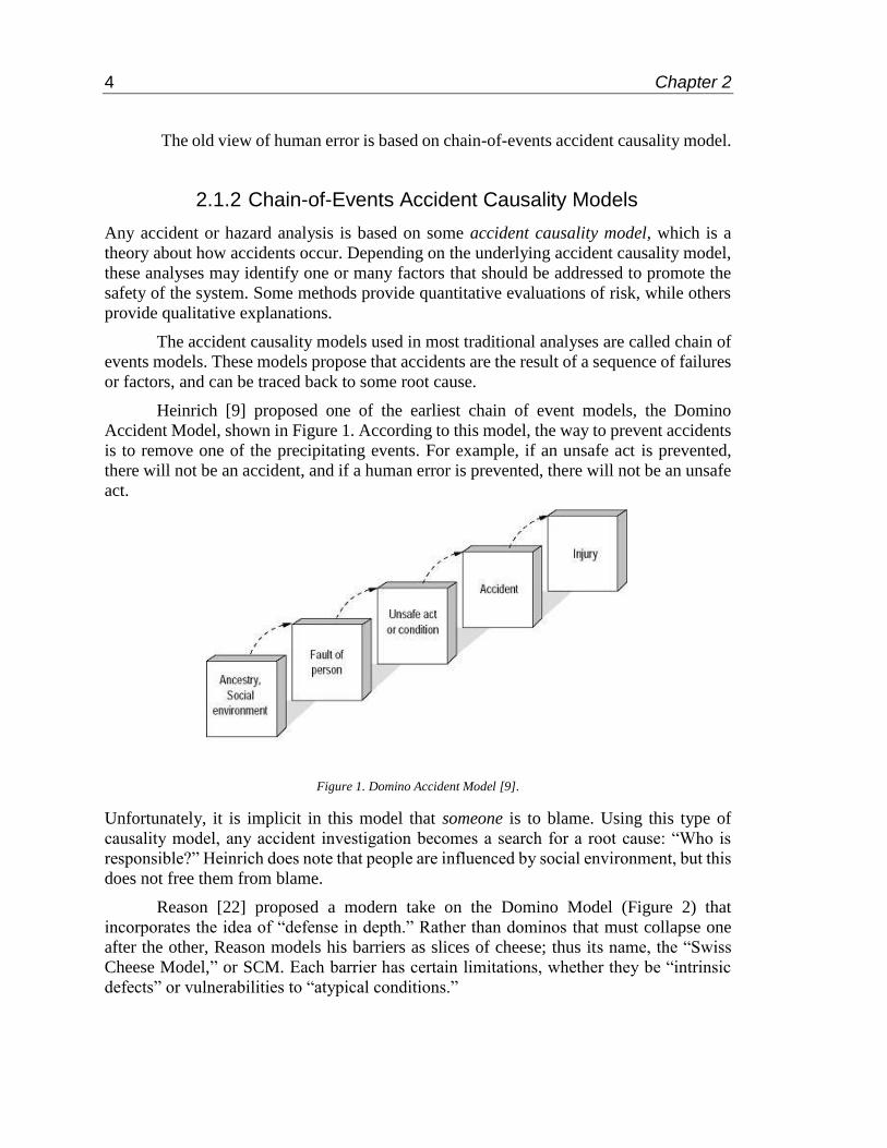

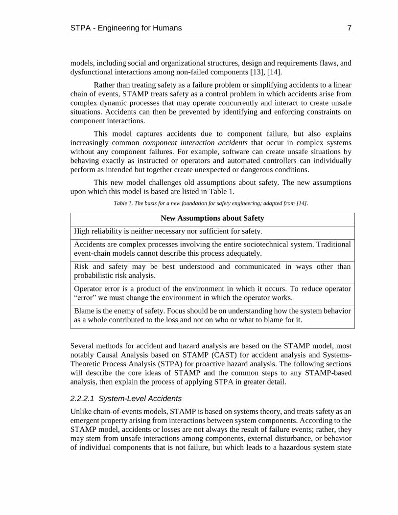


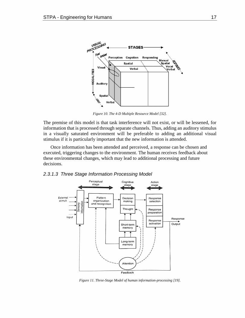


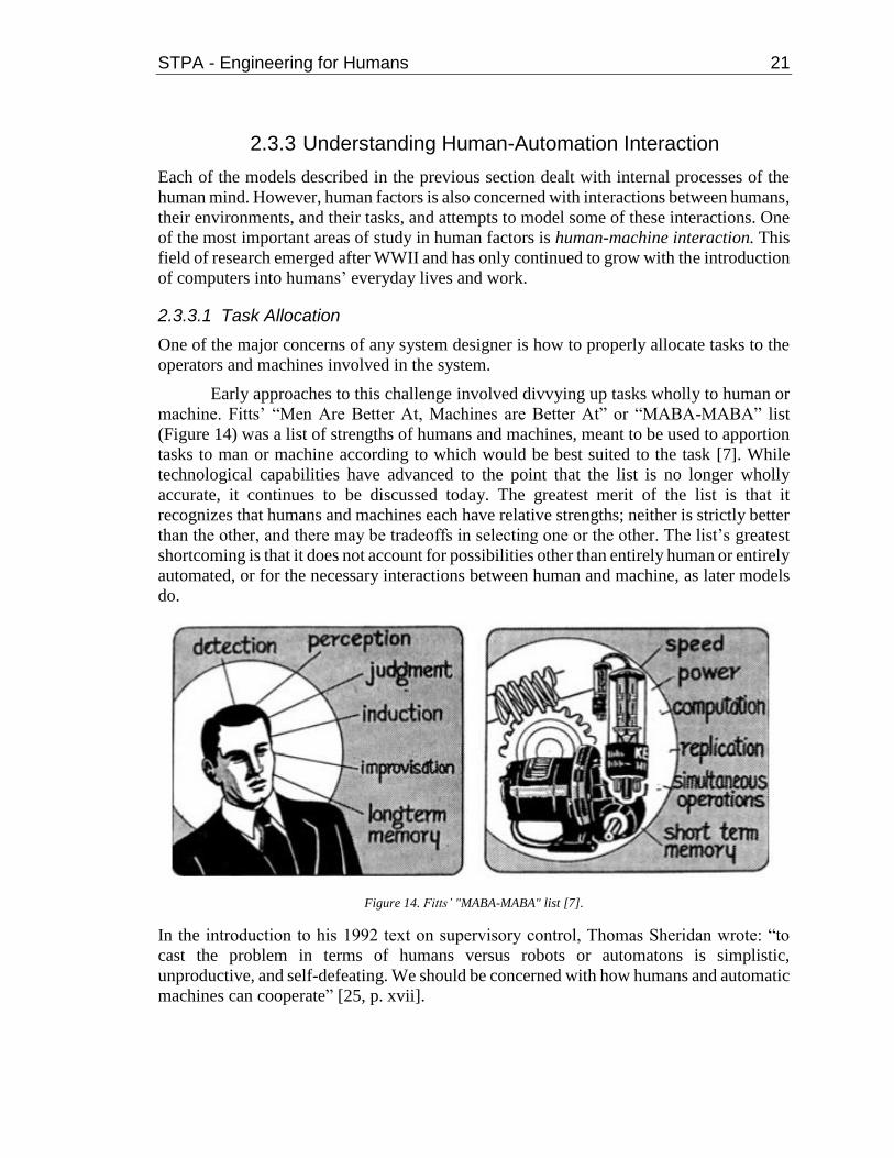

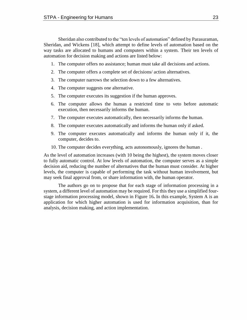
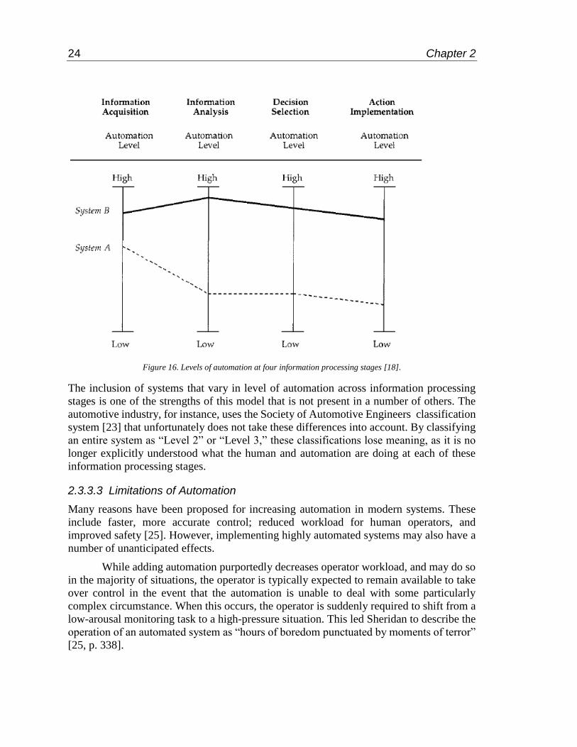


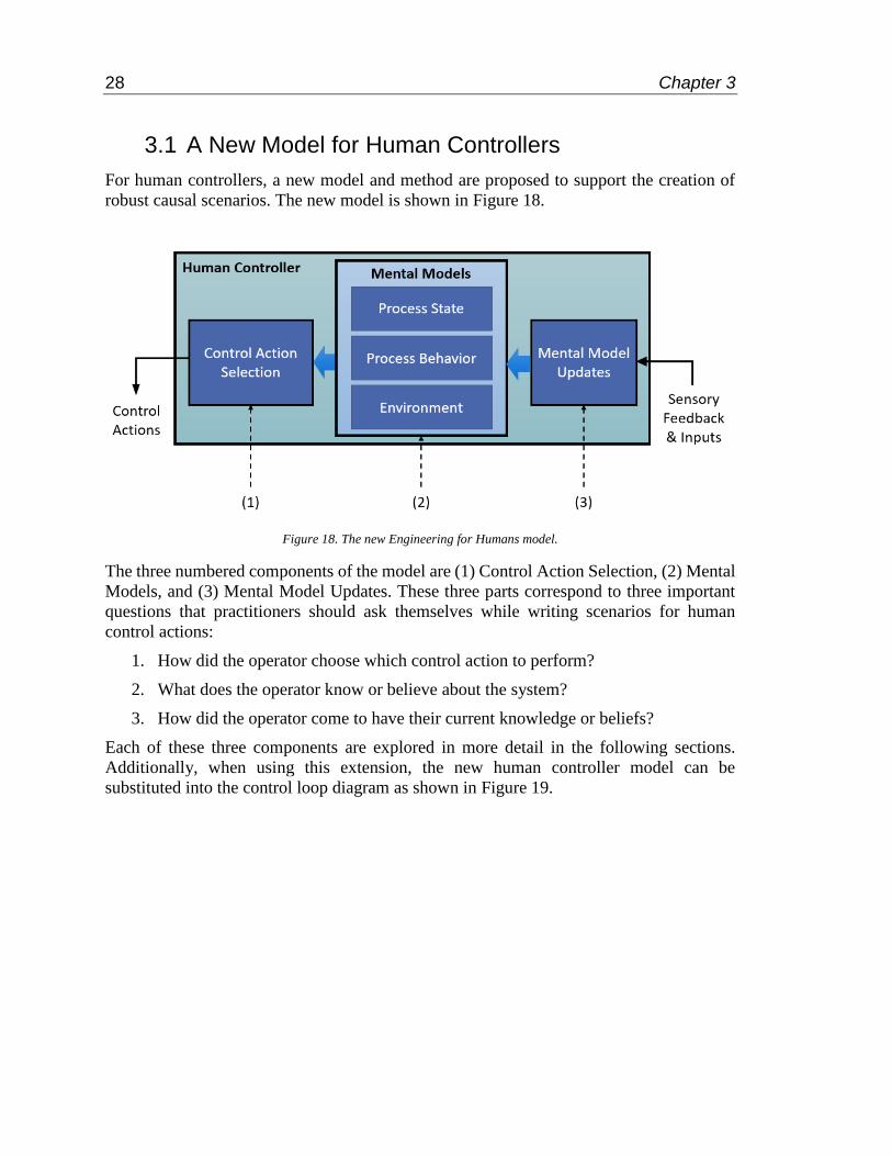


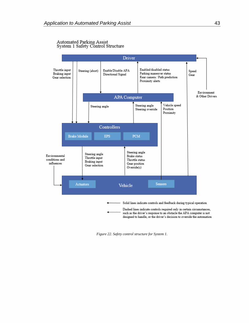


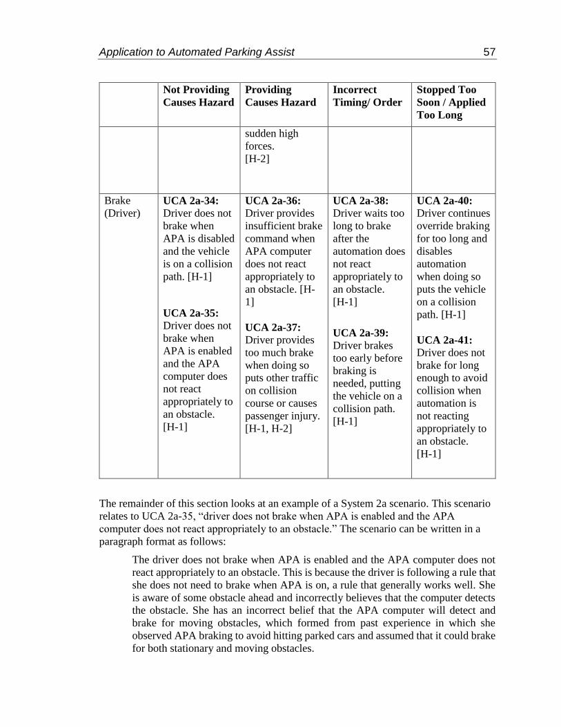


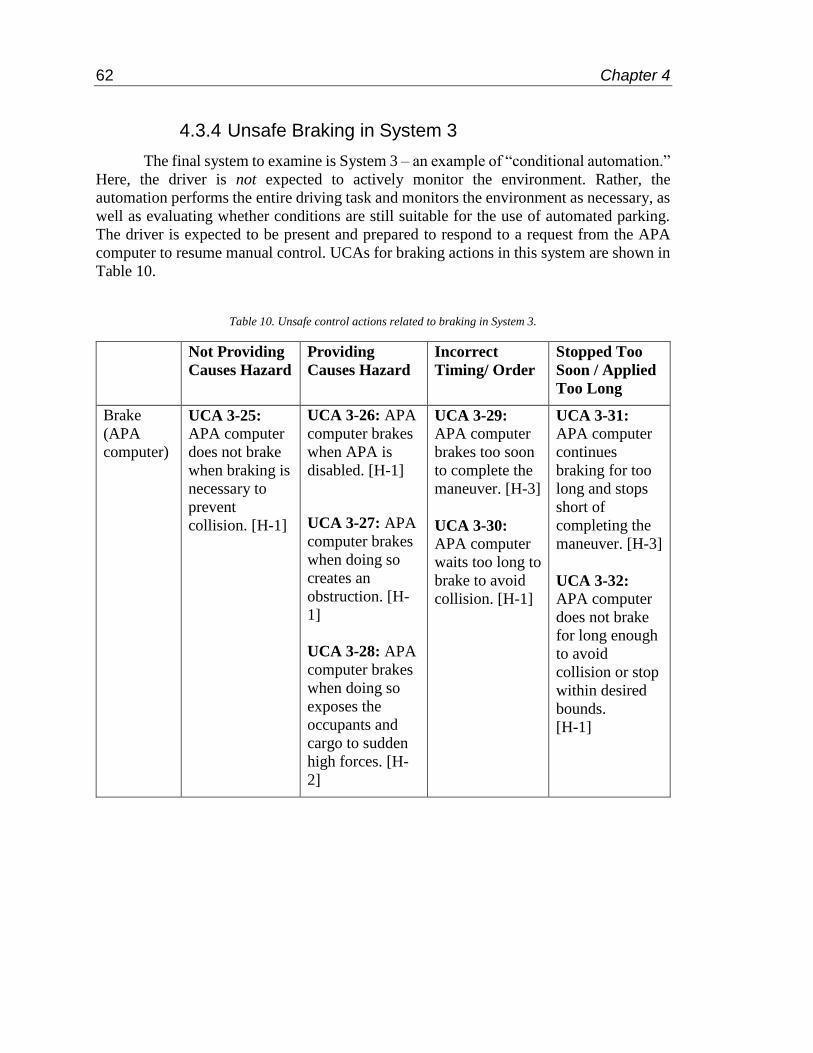
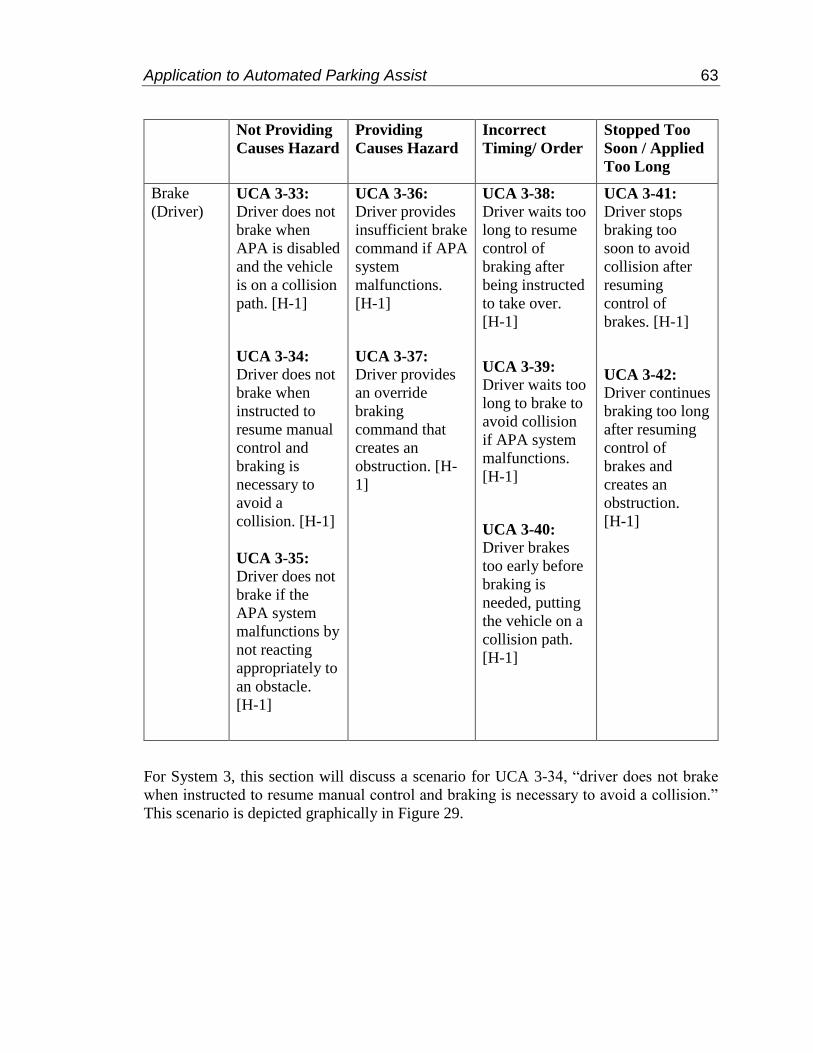


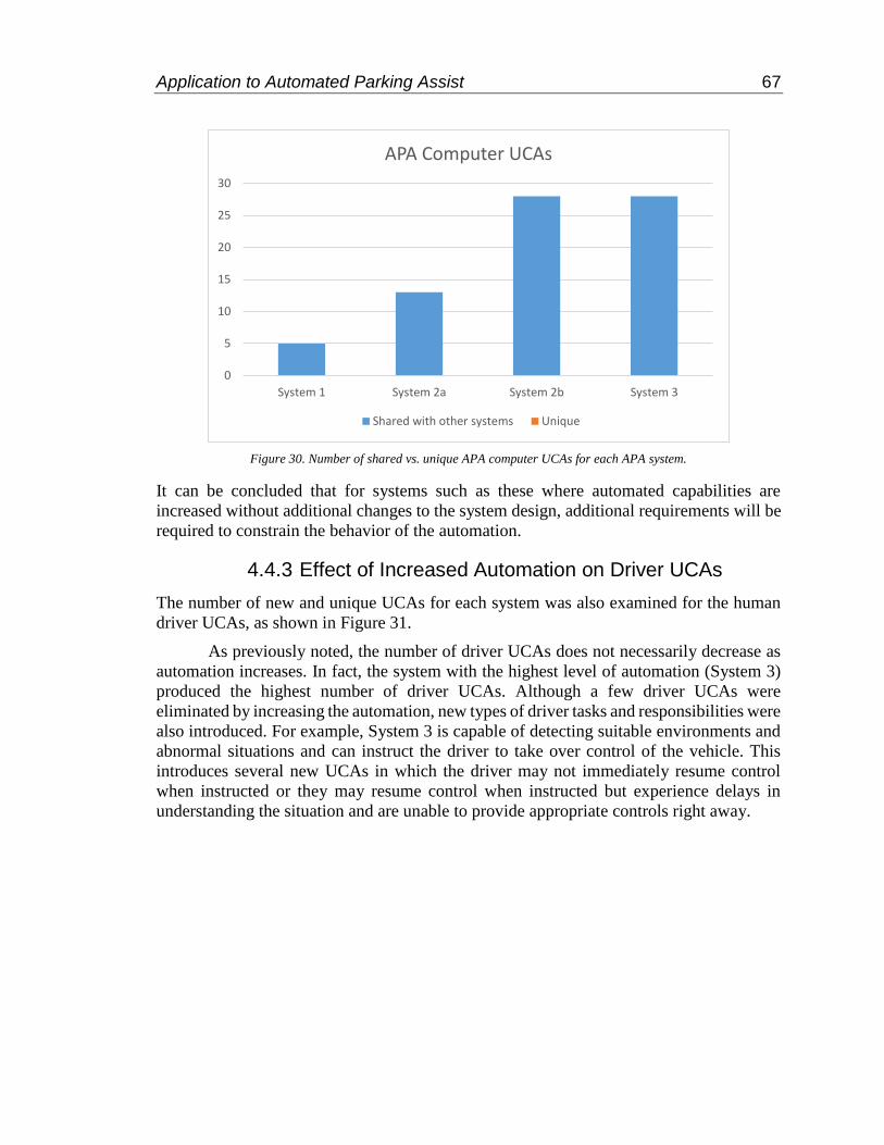


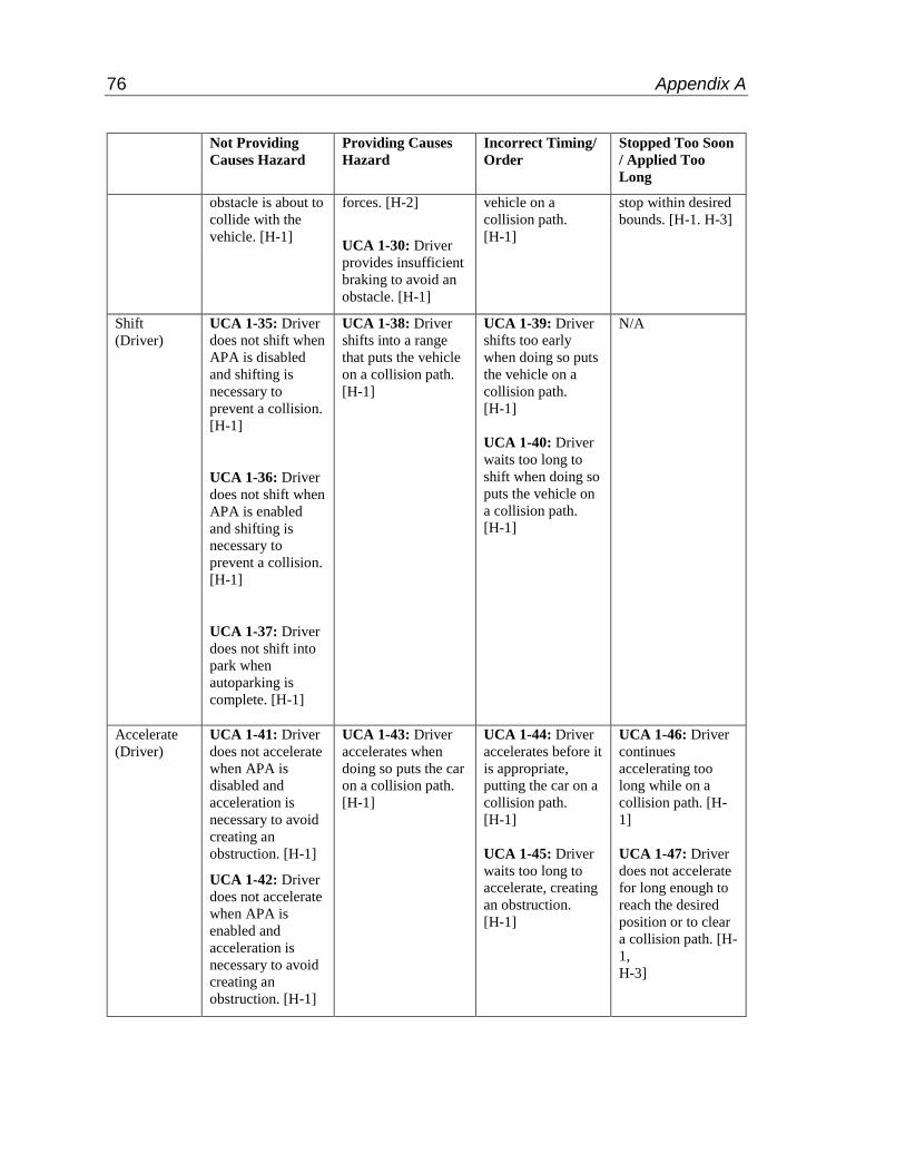


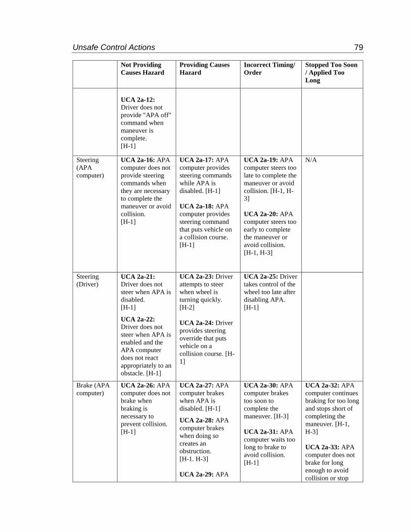

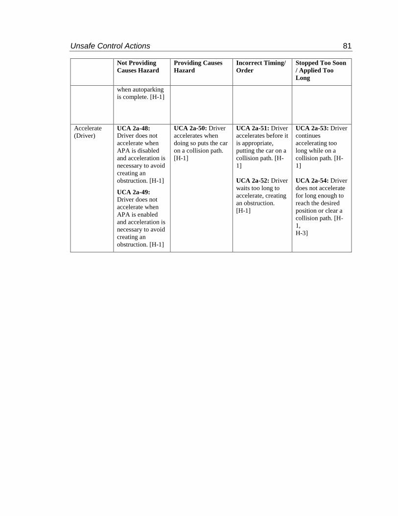


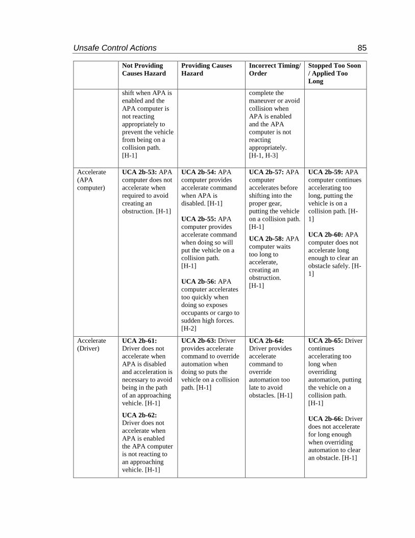


![Hazard Analysis (FMEA & STPA) - Indico [Home]indico.ictp.it/event/a13209/session/2/contribution/21/material/... · Hazard Analysis (FMEA & STPA) Todd Pawlicki, ... First, answer some](https://static.documents.pub/doc/80x56/5af7f1dc7f8b9a190c91d309/hazard-analysis-fmea-stpa-indico-home-analysis-fmea-stpa-todd-pawlicki.jpg)

