312
STR7 FAMILY STR73x SOFTWARE LIBRARY USER MANUAL Rev. 1 September 2005 1Behav
STR7 FAMILY
STR73x
SOFTWARE LIBRARY
USER MANUAL
Rev. 1
September 2005
1Behav
USE IN LIFE SUPPORT DEVICES OR SYSTEMS MUST BE EXPRESSLY AUTHORIZED.
STMicroelectronics PRODUCTS ARE NOT AUTHORIZED FOR USE AS CRITICAL COM-PONENTS IN LIFE SUPPORT DEVICES OR SYSTEMS WITHOUT THE EXPRESS WRIT-TEN APPROVAL OF STMicroelectronics. As used herein:
1.Life support devices or systems are those which (a) are intended for surgical implant into the body, or (b) support or sustain life, and whose failure to perform, when properly used in accordance with instructions for use provid-ed with the product, can be reasonably expect-ed to result in significant injury to the user.
2. A critical component is any component of a life support device or system whose fail-ure to perform can reasonably be expected to cause the failure of the life support device or system, or to affect its safety or effective-ness.
1

STR73x Software Library
USER MANUAL
Rev.1
1 INTRODUCTION
1.1 ABOUT THIS MANUAL
This document is the STR73x software library user manual. It describes the STR73x periph-eral software library: a collection of routines, data structures and macros that cover the fea-tures of each peripheral.
This manual is structured as follows: some definitions, document conventions and software li-brary rules are provided in Chapter 2. Chapter 3 gives some information about the requiredhardware and software environments. Chapter 4 provides a detailed description of the soft-ware library: The package content, the installation steps, the library structure and an exampleon how to use the library. Finally, Chapter 5 describes the software library, peripheral config-uration structure and function descriptions for each peripheral in detail.
1.2 ABOUT STR73X LIBRARY
The STR73x software library is a software package consisting of device drivers for all standardSTR73x peripherals. You can use any STR73x device in applications without in-depth study ofeach peripheral specification.
Each device driver consists of a set of functions covering the functionality of the peripheral.Since all the STR73x peripherals and their corresponding registers are memory-mapped, aperipheral can be easily controlled using ‘C’ code. The source code, developed in ‘C’, is fullydocumented. A basic knowledge of ‘C’ programming is required.
The library contains a complete software in ‘C’ that can be easily ported to any ARM compat-ible ‘C’ compiler.
3/312
iour
Table of Contents
4/312
1
312
1 INTRODUCTION . . . . . . . . . . . . . . . . . . . . . . . . . . . . . . . . . . . . . . . . . . . . . . . . . . . . . . 3
1.1 ABOUT THIS MANUAL . . . . . . . . . . . . . . . . . . . . . . . . . . . . . . . . . . . . . . . . . . . . 31.2 ABOUT STR73X LIBRARY . . . . . . . . . . . . . . . . . . . . . . . . . . . . . . . . . . . . . . . . . 3
2 DOCUMENT AND LIBRARY RULES . . . . . . . . . . . . . . . . . . . . . . . . . . . . . . . . . . . . . 15
2.1 ABBREVIATIONS . . . . . . . . . . . . . . . . . . . . . . . . . . . . . . . . . . . . . . . . . . . . . . . 152.2 STYLE AND SYMBOLS . . . . . . . . . . . . . . . . . . . . . . . . . . . . . . . . . . . . . . . . . . 152.3 NAMING CONVENTIONS . . . . . . . . . . . . . . . . . . . . . . . . . . . . . . . . . . . . . . . . . 162.4 CODING RULES . . . . . . . . . . . . . . . . . . . . . . . . . . . . . . . . . . . . . . . . . . . . . . . . 17
3 SOFTWARE LIBRARY . . . . . . . . . . . . . . . . . . . . . . . . . . . . . . . . . . . . . . . . . . . . . . . . 20
3.1 PACKAGE DESCRIPTION . . . . . . . . . . . . . . . . . . . . . . . . . . . . . . . . . . . . . . . . 203.1.1 Library . . . . . . . . . . . . . . . . . . . . . . . . . . . . . . . . . . . . . . . . . . . . . . . . . . . . 20
3.1.2 Project . . . . . . . . . . . . . . . . . . . . . . . . . . . . . . . . . . . . . . . . . . . . . . . . . . . . 213.1.3 Examples . . . . . . . . . . . . . . . . . . . . . . . . . . . . . . . . . . . . . . . . . . . . . . . . . . 21
3.2 FILE DESCRIPTION . . . . . . . . . . . . . . . . . . . . . . . . . . . . . . . . . . . . . . . . . . . . . 223.3 HOW TO USE THE LIBRARY . . . . . . . . . . . . . . . . . . . . . . . . . . . . . . . . . . . . . . 24
4 PERIPHERAL SOFTWARE . . . . . . . . . . . . . . . . . . . . . . . . . . . . . . . . . . . . . . . . . . . . 25
4.1 ANALOG TO DIGITAL CONVERTER (ADC) . . . . . . . . . . . . . . . . . . . . . . . . . . 254.1.1 Data structures . . . . . . . . . . . . . . . . . . . . . . . . . . . . . . . . . . . . . . . . . . . . . 25
4.1.1.1 ADC Registers structure . . . . . . . . . . . . . . . . . . . . . . . . . . . . . . . 254.1.1.2 ADC_InitTypeDef Structure . . . . . . . . . . . . . . . . . . . . . . . . . . . . . 29
4.1.2 Common Parameter Values . . . . . . . . . . . . . . . . . . . . . . . . . . . . . . . . . . . 304.1.2.1 ADC Modes of Conversion . . . . . . . . . . . . . . . . . . . . . . . . . . . . . . 304.1.2.2 ADC Channels . . . . . . . . . . . . . . . . . . . . . . . . . . . . . . . . . . . . . . . 314.1.2.3 ADC Flags . . . . . . . . . . . . . . . . . . . . . . . . . . . . . . . . . . . . . . . . . . 314.1.2.4 ADC IT . . . . . . . . . . . . . . . . . . . . . . . . . . . . . . . . . . . . . . . . . . . . . 324.1.2.5 ADC Sampling and Conversion Prescalers . . . . . . . . . . . . . . . . . 334.1.2.6 ADC Analog Watchdogs . . . . . . . . . . . . . . . . . . . . . . . . . . . . . . . 334.1.2.7 ADC DMA Channels . . . . . . . . . . . . . . . . . . . . . . . . . . . . . . . . . . 33
4.1.3 Software Library Functions . . . . . . . . . . . . . . . . . . . . . . . . . . . . . . . . . . . . 34
4.1.3.1 ADC_Init . . . . . . . . . . . . . . . . . . . . . . . . . . . . . . . . . . . . . . . . . . . . 364.1.3.2 ADC_DeInit . . . . . . . . . . . . . . . . . . . . . . . . . . . . . . . . . . . . . . . . . 374.1.3.3 ADC_StructInit . . . . . . . . . . . . . . . . . . . . . . . . . . . . . . . . . . . . . . 374.1.3.4 ADC_CalibrationStart . . . . . . . . . . . . . . . . . . . . . . . . . . . . . . . . . 384.1.3.5 ADC_ConversionCmd . . . . . . . . . . . . . . . . . . . . . . . . . . . . . . . . . 384.1.3.6 ADC_Cmd . . . . . . . . . . . . . . . . . . . . . . . . . . . . . . . . . . . . . . . . . . 394.1.3.7 ADC_AutoClockConfig . . . . . . . . . . . . . . . . . . . . . . . . . . . . . . . . . 394.1.3.8 ADC_ChannelsSelect . . . . . . . . . . . . . . . . . . . . . . . . . . . . . . . . . 404.1.3.9 ADC_PrescalersConfig . . . . . . . . . . . . . . . . . . . . . . . . . . . . . . . . 414.1.3.10 ADC_ITConfig . . . . . . . . . . . . . . . . . . . . . . . . . . . . . . . . . . . . . . . 424.1.3.11 ADC_FlagStatus . . . . . . . . . . . . . . . . . . . . . . . . . . . . . . . . . . . . . 43
INTRODUCTION - ABOUT STR73X LIBRARY
4.1.3.12 ADC_FlagClear . . . . . . . . . . . . . . . . . . . . . . . . . . . . . . . . . . . . . . 434.1.3.13 ADC_GetConversionValue . . . . . . . . . . . . . . . . . . . . . . . . . . . . . 444.1.3.14 ADC_AnalogWatchdogConfig . . . . . . . . . . . . . . . . . . . . . . . . . . . 454.1.3.15 ADC_AnalogWatchdogEnable . . . . . . . . . . . . . . . . . . . . . . . . . . 464.1.3.16 ADC_GetAnalogWatchdogResult . . . . . . . . . . . . . . . . . . . . . . . . 474.1.3.17 ADC_InjectedConversionStart . . . . . . . . . . . . . . . . . . . . . . . . . . . 474.1.3.18 ADC_InjectedChannelsSelect . . . . . . . . . . . . . . . . . . . . . . . . . . . 484.1.3.19 ADC_DMAConfig . . . . . . . . . . . . . . . . . . . . . . . . . . . . . . . . . . . . . 494.1.3.20 ADC_DMACmd . . . . . . . . . . . . . . . . . . . . . . . . . . . . . . . . . . . . . . 504.1.3.21 ADC_DMAFirstEnabledChannel . . . . . . . . . . . . . . . . . . . . . . . . . 50
4.2 BUFFERED SERIAL PERIPHERAL INTERFACE (BSPI) . . . . . . . . . . . . . . . . . 514.2.1 Data structures . . . . . . . . . . . . . . . . . . . . . . . . . . . . . . . . . . . . . . . . . . . . . 51
4.2.1.1 BSPI Register Structure . . . . . . . . . . . . . . . . . . . . . . . . . . . . . . . . 514.2.1.2 BSPI_InitTypeDef Structure . . . . . . . . . . . . . . . . . . . . . . . . . . . . . 52
4.2.2 Common Parameter Values . . . . . . . . . . . . . . . . . . . . . . . . . . . . . . . . . . . 54
4.2.2.1 BSPI interrupts . . . . . . . . . . . . . . . . . . . . . . . . . . . . . . . . . . . . . . . 544.2.2.2 BSPI transmit interrupt . . . . . . . . . . . . . . . . . . . . . . . . . . . . . . . . . 544.2.2.3 BSPI receive interrupt . . . . . . . . . . . . . . . . . . . . . . . . . . . . . . . . . 554.2.2.4 BSPI DMA requests . . . . . . . . . . . . . . . . . . . . . . . . . . . . . . . . . . . 554.2.2.5 BSPI DMA transmit burst length . . . . . . . . . . . . . . . . . . . . . . . . . 554.2.2.6 BSPI DMA receive burst length . . . . . . . . . . . . . . . . . . . . . . . . . . 554.2.2.7 BSPI flags . . . . . . . . . . . . . . . . . . . . . . . . . . . . . . . . . . . . . . . . . . 55
4.2.3 Software Library Functions . . . . . . . . . . . . . . . . . . . . . . . . . . . . . . . . . . . . 56
4.2.3.1 BSPI_DeInit . . . . . . . . . . . . . . . . . . . . . . . . . . . . . . . . . . . . . . . . . 574.2.3.2 BSPI_Init . . . . . . . . . . . . . . . . . . . . . . . . . . . . . . . . . . . . . . . . . . . 574.2.3.3 BSPI_StructInit . . . . . . . . . . . . . . . . . . . . . . . . . . . . . . . . . . . . . . 584.2.3.4 BSPI_Cmd . . . . . . . . . . . . . . . . . . . . . . . . . . . . . . . . . . . . . . . . . 594.2.3.5 BSPI_RxFifoDisable . . . . . . . . . . . . . . . . . . . . . . . . . . . . . . . . . . 594.2.3.6 BSPI_ITConfig . . . . . . . . . . . . . . . . . . . . . . . . . . . . . . . . . . . . . . . 604.2.3.7 BSPI_TxITConfig . . . . . . . . . . . . . . . . . . . . . . . . . . . . . . . . . . . . . 614.2.3.8 BSPI_RxITConfig . . . . . . . . . . . . . . . . . . . . . . . . . . . . . . . . . . . . . 614.2.3.9 BSPI_DMAConfig . . . . . . . . . . . . . . . . . . . . . . . . . . . . . . . . . . . . 624.2.3.10 BSPI_DMATxBurstConfig . . . . . . . . . . . . . . . . . . . . . . . . . . . . . . 634.2.3.11 BSPI_DMARxBurstConfig . . . . . . . . . . . . . . . . . . . . . . . . . . . . . . 634.2.3.12 BSPI_DMACmd . . . . . . . . . . . . . . . . . . . . . . . . . . . . . . . . . . . . . 644.2.3.13 BSPI_WordSend . . . . . . . . . . . . . . . . . . . . . . . . . . . . . . . . . . . . . 644.2.3.14 BSPI_BufferSend . . . . . . . . . . . . . . . . . . . . . . . . . . . . . . . . . . . . 654.2.3.15 BSPI_WordReceive . . . . . . . . . . . . . . . . . . . . . . . . . . . . . . . . . . 664.2.3.16 BSPI_BufferReceive . . . . . . . . . . . . . . . . . . . . . . . . . . . . . . . . . . 664.2.3.17 BSPI_FlagStatus . . . . . . . . . . . . . . . . . . . . . . . . . . . . . . . . . . . . . 67
4.3 CONTROLLER AREA NETWORK (CAN) . . . . . . . . . . . . . . . . . . . . . . . . . . . . . 684.3.1 Data structures . . . . . . . . . . . . . . . . . . . . . . . . . . . . . . . . . . . . . . . . . . . . . 68
4.3.1.1 CAN Registers structure . . . . . . . . . . . . . . . . . . . . . . . . . . . . . . . 68
5/312

INTRODUCTION - ABOUT STR73X LIBRARY
4.3.1.2 CAN_InitTypeDef Structure . . . . . . . . . . . . . . . . . . . . . . . . . . . . . 724.3.2 Common Parameter Values . . . . . . . . . . . . . . . . . . . . . . . . . . . . . . . . . . . 72
4.3.2.1 CAN Control . . . . . . . . . . . . . . . . . . . . . . . . . . . . . . . . . . . . . . . . . 724.3.2.2 CAN Status . . . . . . . . . . . . . . . . . . . . . . . . . . . . . . . . . . . . . . . . . 734.3.2.3 CAN Test . . . . . . . . . . . . . . . . . . . . . . . . . . . . . . . . . . . . . . . . . . . 734.3.2.4 CAN IFn / Command Request . . . . . . . . . . . . . . . . . . . . . . . . . . . 734.3.2.5 CAN IFn / Command Mask . . . . . . . . . . . . . . . . . . . . . . . . . . . . . 744.3.2.6 CAN IFn / Mask 2 . . . . . . . . . . . . . . . . . . . . . . . . . . . . . . . . . . . . . 744.3.2.7 CAN IFn / Arbitration 2 . . . . . . . . . . . . . . . . . . . . . . . . . . . . . . . . . 744.3.2.8 CAN IFn / Message Control . . . . . . . . . . . . . . . . . . . . . . . . . . . . . 74
4.3.3 Software Library Functions . . . . . . . . . . . . . . . . . . . . . . . . . . . . . . . . . . . . 75
4.3.3.1 CAN_Init . . . . . . . . . . . . . . . . . . . . . . . . . . . . . . . . . . . . . . . . . . . . 764.3.3.2 CAN_DeInit . . . . . . . . . . . . . . . . . . . . . . . . . . . . . . . . . . . . . . . . . 774.3.3.3 CAN_StructInit . . . . . . . . . . . . . . . . . . . . . . . . . . . . . . . . . . . . . . 774.3.3.4 CAN_EnterInitMode . . . . . . . . . . . . . . . . . . . . . . . . . . . . . . . . . . . 784.3.3.5 CAN_LeaveInitMode . . . . . . . . . . . . . . . . . . . . . . . . . . . . . . . . . . 794.3.3.6 CAN_EnterTestMode . . . . . . . . . . . . . . . . . . . . . . . . . . . . . . . . . . 804.3.3.7 CAN_LeaveTestMode . . . . . . . . . . . . . . . . . . . . . . . . . . . . . . . . . 814.3.3.8 CAN_SetBitrate . . . . . . . . . . . . . . . . . . . . . . . . . . . . . . . . . . . . . . 814.3.3.9 CAN_SetTiming . . . . . . . . . . . . . . . . . . . . . . . . . . . . . . . . . . . . . . 824.3.3.10 CAN_SetUnusedMsgObj . . . . . . . . . . . . . . . . . . . . . . . . . . . . . . . 834.3.3.11 CAN_SetTxMsgObj . . . . . . . . . . . . . . . . . . . . . . . . . . . . . . . . . . . 844.3.3.12 CAN_SetRxMsgObj . . . . . . . . . . . . . . . . . . . . . . . . . . . . . . . . . . . 854.3.3.13 CAN_InvalidateAllMsgObj . . . . . . . . . . . . . . . . . . . . . . . . . . . . . . 874.3.3.14 CAN_ReleaseMessage . . . . . . . . . . . . . . . . . . . . . . . . . . . . . . . . 874.3.3.15 CAN_ReleaseTxMessage . . . . . . . . . . . . . . . . . . . . . . . . . . . . . . 884.3.3.16 CAN_ReleaseRxMessage . . . . . . . . . . . . . . . . . . . . . . . . . . . . . . 894.3.3.17 CAN_SendMessage . . . . . . . . . . . . . . . . . . . . . . . . . . . . . . . . . . . 904.3.3.18 CAN_ReceiveMessage . . . . . . . . . . . . . . . . . . . . . . . . . . . . . . . . 914.3.3.19 CAN_WaitEndOfTx . . . . . . . . . . . . . . . . . . . . . . . . . . . . . . . . . . . 924.3.3.20 CAN_BasicSendMessage . . . . . . . . . . . . . . . . . . . . . . . . . . . . . . 934.3.3.21 CAN_BasicReceiveMessage . . . . . . . . . . . . . . . . . . . . . . . . . . . . 944.3.3.22 CAN_IsMessageWaiting . . . . . . . . . . . . . . . . . . . . . . . . . . . . . . . 954.3.3.23 CAN_IsTransmitRequested . . . . . . . . . . . . . . . . . . . . . . . . . . . . . 964.3.3.24 CAN_IsInterruptPending . . . . . . . . . . . . . . . . . . . . . . . . . . . . . . . 974.3.3.25 CAN_IsObjectValid . . . . . . . . . . . . . . . . . . . . . . . . . . . . . . . . . . . 98
4.4 CONFIGURATION REGISTER (CFG) . . . . . . . . . . . . . . . . . . . . . . . . . . . . . . . 994.4.1 Data structures . . . . . . . . . . . . . . . . . . . . . . . . . . . . . . . . . . . . . . . . . . . . . 99
4.4.1.1 CFG Register structure . . . . . . . . . . . . . . . . . . . . . . . . . . . . . . . . 994.4.2 Common Parameter Values . . . . . . . . . . . . . . . . . . . . . . . . . . . . . . . . . . 101
4.4.2.1 Peripheral clock gating lines . . . . . . . . . . . . . . . . . . . . . . . . . . . 1014.4.2.2 CFG flags . . . . . . . . . . . . . . . . . . . . . . . . . . . . . . . . . . . . . . . . . . 1024.4.2.3 CFG MEM Remap . . . . . . . . . . . . . . . . . . . . . . . . . . . . . . . . . . . 102
6/312

INTRODUCTION - ABOUT STR73X LIBRARY
4.4.3 Software Library Functions . . . . . . . . . . . . . . . . . . . . . . . . . . . . . . . . . . . 103
4.4.3.1 CFG_PeripheralClockConfig . . . . . . . . . . . . . . . . . . . . . . . . . . . 1034.4.3.2 CFG_EmulationPeripheralClockConfig . . . . . . . . . . . . . . . . . . . 1044.4.3.3 CFG_RemapConfig . . . . . . . . . . . . . . . . . . . . . . . . . . . . . . . . . . 1044.4.3.4 CFG_PeripheralClockStop . . . . . . . . . . . . . . . . . . . . . . . . . . . . . 1054.4.3.5 CFG_PeripheralClockStart . . . . . . . . . . . . . . . . . . . . . . . . . . . . . 1054.4.3.6 CFG_DeviceID . . . . . . . . . . . . . . . . . . . . . . . . . . . . . . . . . . . . . . 1064.4.3.7 CFG_FlashPowerOnDelay . . . . . . . . . . . . . . . . . . . . . . . . . . . . . 1064.4.3.8 CFG_FlagStatus . . . . . . . . . . . . . . . . . . . . . . . . . . . . . . . . . . . . 107
4.5 CLOCK MONITOR UNIT (CMU) . . . . . . . . . . . . . . . . . . . . . . . . . . . . . . . . . . . 1084.5.1 Data Structures . . . . . . . . . . . . . . . . . . . . . . . . . . . . . . . . . . . . . . . . . . . . 108
4.5.1.1 CMU Register Structure . . . . . . . . . . . . . . . . . . . . . . . . . . . . . . . 1084.5.1.2 CMU_InitTypeDef Structure . . . . . . . . . . . . . . . . . . . . . . . . . . . . 109
4.5.2 Common Parameter Values . . . . . . . . . . . . . . . . . . . . . . . . . . . . . . . . . . 111
4.5.2.1 CMU Oscillator Mode . . . . . . . . . . . . . . . . . . . . . . . . . . . . . . . . . 1114.5.2.2 CMU interrupts . . . . . . . . . . . . . . . . . . . . . . . . . . . . . . . . . . . . . 1114.5.2.3 CMU Stop Oscillator . . . . . . . . . . . . . . . . . . . . . . . . . . . . . . . . . . 1124.5.2.4 CMU Flag Status . . . . . . . . . . . . . . . . . . . . . . . . . . . . . . . . . . . . 112
4.5.3 Software Library Functions . . . . . . . . . . . . . . . . . . . . . . . . . . . . . . . . . . . 112
4.5.3.1 CMU_Init . . . . . . . . . . . . . . . . . . . . . . . . . . . . . . . . . . . . . . . . . . 1134.5.3.2 CMU_DeInit . . . . . . . . . . . . . . . . . . . . . . . . . . . . . . . . . . . . . . . . 1144.5.3.3 CMU_StructInit . . . . . . . . . . . . . . . . . . . . . . . . . . . . . . . . . . . . . . 1144.5.3.4 CMU_GetOSCFrequency . . . . . . . . . . . . . . . . . . . . . . . . . . . . . 1154.5.3.5 CMU_ITClear . . . . . . . . . . . . . . . . . . . . . . . . . . . . . . . . . . . . . . 1154.5.3.6 CMU_FlagClear . . . . . . . . . . . . . . . . . . . . . . . . . . . . . . . . . . . . 1164.5.3.7 CMU_Lock . . . . . . . . . . . . . . . . . . . . . . . . . . . . . . . . . . . . . . 1164.5.3.8 CMU_StopOscConfig . . . . . . . . . . . . . . . . . . . . . . . . . . . . . . . . 1174.5.3.9 CMU_FlagStatus . . . . . . . . . . . . . . . . . . . . . . . . . . . . . . . . . . . . 1174.5.3.10 CMU_ITConfig . . . . . . . . . . . . . . . . . . . . . . . . . . . . . . . . . . . . 1184.5.3.11 CMU_ResetConfig . . . . . . . . . . . . . . . . . . . . . . . . . . . . . . . . . 1184.5.3.12 CMU_ModeOscConfig . . . . . . . . . . . . . . . . . . . . . . . . . . . . . . . 119
4.6 DIRECT MEMORY ACCESS (DMA) . . . . . . . . . . . . . . . . . . . . . . . . . . . . . . . . 1204.6.1 Data structures . . . . . . . . . . . . . . . . . . . . . . . . . . . . . . . . . . . . . . . . . . . . 120
4.6.1.1 DMA Register structure . . . . . . . . . . . . . . . . . . . . . . . . . . . . . . . 1204.6.1.2 DMA_InitTypeDef Structure . . . . . . . . . . . . . . . . . . . . . . . . . . . . 124
4.6.2 Common Parameter Values . . . . . . . . . . . . . . . . . . . . . . . . . . . . . . . . . . 127
4.6.2.1 DMA priority . . . . . . . . . . . . . . . . . . . . . . . . . . . . . . . . . . . . . . . . 1274.6.2.2 DMA interrupts . . . . . . . . . . . . . . . . . . . . . . . . . . . . . . . . . . . . . . 1284.6.2.3 DMA flags . . . . . . . . . . . . . . . . . . . . . . . . . . . . . . . . . . . . . . . . . . 128
4.6.3 Software Library Functions . . . . . . . . . . . . . . . . . . . . . . . . . . . . . . . . . . . 129
4.6.3.1 DMA_DeInit . . . . . . . . . . . . . . . . . . . . . . . . . . . . . . . . . . . . . . . . 1304.6.3.2 DMA_Init . . . . . . . . . . . . . . . . . . . . . . . . . . . . . . . . . . . . . . . . . . 130
7/312

INTRODUCTION - ABOUT STR73X LIBRARY
4.6.3.3 DMA_StructInit . . . . . . . . . . . . . . . . . . . . . . . . . . . . . . . . . . . . . 1314.6.3.4 DMA_AHBArbitrationConfig . . . . . . . . . . . . . . . . . . . . . . . . . . . 1324.6.3.5 DMA_Cmd . . . . . . . . . . . . . . . . . . . . . . . . . . . . . . . . . . . . . . . . . 1324.6.3.6 DMA_TimeOutConfig . . . . . . . . . . . . . . . . . . . . . . . . . . . . . . . . 1334.6.3.7 DMA_ITConfig . . . . . . . . . . . . . . . . . . . . . . . . . . . . . . . . . . . . . . 1344.6.3.8 DMA_GetCurrDSTAddr . . . . . . . . . . . . . . . . . . . . . . . . . . . . . . . 1354.6.3.9 DMA_GetCurrSRCAddr . . . . . . . . . . . . . . . . . . . . . . . . . . . . . . 1354.6.3.10 DMA_GetTerminalCounter . . . . . . . . . . . . . . . . . . . . . . . . . . . . 1364.6.3.11 DMA_LastBufferSweepConfig . . . . . . . . . . . . . . . . . . . . . . . . . 1374.6.3.12 DMA_LastBufferAddrConfig . . . . . . . . . . . . . . . . . . . . . . . . . . . 1384.6.3.13 DMA_FlagStatus . . . . . . . . . . . . . . . . . . . . . . . . . . . . . . . . . . . . 1394.6.3.14 DMA_FlagClear . . . . . . . . . . . . . . . . . . . . . . . . . . . . . . . . . . . . . 140
4.7 ENHANCED INTERRUPT CONTROLLER (EIC) . . . . . . . . . . . . . . . . . . . . . . 1414.7.1 Data Structures . . . . . . . . . . . . . . . . . . . . . . . . . . . . . . . . . . . . . . . . . . . . 141
4.7.1.1 EIC Register Structure . . . . . . . . . . . . . . . . . . . . . . . . . . . . . . . . 1414.7.1.2 EIC_InitTypeDef Structure . . . . . . . . . . . . . . . . . . . . . . . . . . . . . 1424.7.1.3 EXTIT_Trigger structure . . . . . . . . . . . . . . . . . . . . . . . . . . . . . . . 145
4.7.2 Software Library Functions . . . . . . . . . . . . . . . . . . . . . . . . . . . . . . . . . . . 146
4.7.2.1 EIC_Init . . . . . . . . . . . . . . . . . . . . . . . . . . . . . . . . . . . . . . . . . . . 1464.7.2.2 EIC_DeInit . . . . . . . . . . . . . . . . . . . . . . . . . . . . . . . . . . . . . . . . . 1474.7.2.3 EIC_StructInit . . . . . . . . . . . . . . . . . . . . . . . . . . . . . . . . . . . . . . . 1484.7.2.4 EIC_CurrentPriorityLevelConfig . . . . . . . . . . . . . . . . . . . . . . . . . 1484.7.2.5 EIC_IRQChannelConfig . . . . . . . . . . . . . . . . . . . . . . . . . . . . . . . 1494.7.2.6 EIC_ExternalITTriggerConfig . . . . . . . . . . . . . . . . . . . . . . . . . . . 1504.7.2.7 EIC_IRQCmd . . . . . . . . . . . . . . . . . . . . . . . . . . . . . . . . . . . . . . . 1504.7.2.8 EIC_FIQCmd . . . . . . . . . . . . . . . . . . . . . . . . . . . . . . . . . . . . . . . 1514.7.2.9 EIC_CurrentPriorityLevelValue . . . . . . . . . . . . . . . . . . . . . . . . . 1514.7.2.10 EIC_CurrentIRQChannelValue . . . . . . . . . . . . . . . . . . . . . . . . . 1524.7.2.11 EIC_CurrentFIQChannelValue . . . . . . . . . . . . . . . . . . . . . . . . . . 1524.7.2.12 EIC_FIQPendingBitClear . . . . . . . . . . . . . . . . . . . . . . . . . . . . . . 1534.7.2.13 EIC_FIQChannelConfig . . . . . . . . . . . . . . . . . . . . . . . . . . . . . . . 1534.7.2.14 EIC_IRQChannelPriorityConfig . . . . . . . . . . . . . . . . . . . . . . . . . 154
4.8 FLASH . . . . . . . . . . . . . . . . . . . . . . . . . . . . . . . . . . . . . . . . . . . . . . . . . . . . . . . 1554.8.1 Data structures . . . . . . . . . . . . . . . . . . . . . . . . . . . . . . . . . . . . . . . . . . . . 155
4.8.1.1 Flash Register Structure . . . . . . . . . . . . . . . . . . . . . . . . . . . . . . 1554.8.1.2 Flash Protection Register Structure . . . . . . . . . . . . . . . . . . . . . . 156
4.8.2 Common Parameter Values . . . . . . . . . . . . . . . . . . . . . . . . . . . . . . . . . . 157
4.8.2.1 Bank0 Flash sectors . . . . . . . . . . . . . . . . . . . . . . . . . . . . . . . . . . 1574.8.2.2 Operation to resume . . . . . . . . . . . . . . . . . . . . . . . . . . . . . . . . . 1574.8.2.3 Flash flags . . . . . . . . . . . . . . . . . . . . . . . . . . . . . . . . . . . . . . . . . 158
4.8.3 Software Library Functions . . . . . . . . . . . . . . . . . . . . . . . . . . . . . . . . . . . 158
4.8.3.1 FLASH_DeInit . . . . . . . . . . . . . . . . . . . . . . . . . . . . . . . . . . . . . . 1594.8.3.2 FLASH_WordWrite . . . . . . . . . . . . . . . . . . . . . . . . . . . . . . . . . . 159
8/312

INTRODUCTION - ABOUT STR73X LIBRARY
4.8.3.3 FLASH_DWordWrite . . . . . . . . . . . . . . . . . . . . . . . . . . . . . . . . . 1604.8.3.4 FLASH_BlockWrite . . . . . . . . . . . . . . . . . . . . . . . . . . . . . . . . . . 1614.8.3.5 FLASH_WordRead . . . . . . . . . . . . . . . . . . . . . . . . . . . . . . . . . . 1614.8.3.6 FLASH_BlockRead . . . . . . . . . . . . . . . . . . . . . . . . . . . . . . . . . . 1624.8.3.7 FLASH_SectorErase . . . . . . . . . . . . . . . . . . . . . . . . . . . . . . . . . 1634.8.3.8 FLASH_Suspend . . . . . . . . . . . . . . . . . . . . . . . . . . . . . . . . . . . 1634.8.3.9 FLASH_Resume . . . . . . . . . . . . . . . . . . . . . . . . . . . . . . . . . . . . 1644.8.3.10 FLASH_PowerDownConfig . . . . . . . . . . . . . . . . . . . . . . . . . . . . 1644.8.3.11 FLASH_ITConfig . . . . . . . . . . . . . . . . . . . . . . . . . . . . . . . . . . . . 1654.8.3.12 FLASH_FlagStatus . . . . . . . . . . . . . . . . . . . . . . . . . . . . . . . . . . 165
4.9 GENERAL PURPOSE INPUT OUTPUT (GPIO) . . . . . . . . . . . . . . . . . . . . . . . 1674.9.1 Data Structures . . . . . . . . . . . . . . . . . . . . . . . . . . . . . . . . . . . . . . . . . . . . 167
4.9.1.1 GPIO Register Structure . . . . . . . . . . . . . . . . . . . . . . . . . . . . . . 1674.9.1.2 GPIO_InitTypeDef Structure . . . . . . . . . . . . . . . . . . . . . . . . . . . 169
4.9.2 Common Parameter Values . . . . . . . . . . . . . . . . . . . . . . . . . . . . . . . . . . 170
4.9.2.1 GPIOx values . . . . . . . . . . . . . . . . . . . . . . . . . . . . . . . . . . . . . . . 1704.9.2.2 GPIO pin values . . . . . . . . . . . . . . . . . . . . . . . . . . . . . . . . . . . . . 1714.9.2.3 GPIO byte values . . . . . . . . . . . . . . . . . . . . . . . . . . . . . . . . . . . . 171
4.9.3 Software Library Functions . . . . . . . . . . . . . . . . . . . . . . . . . . . . . . . . . . . 172
4.9.3.1 GPIO_Init . . . . . . . . . . . . . . . . . . . . . . . . . . . . . . . . . . . . . . . . . . 1724.9.3.2 GPIO_DeInit . . . . . . . . . . . . . . . . . . . . . . . . . . . . . . . . . . . . . . . 1744.9.3.3 GPIO_StructInit . . . . . . . . . . . . . . . . . . . . . . . . . . . . . . . . . . . . . 1744.9.3.4 GPIO_BitRead . . . . . . . . . . . . . . . . . . . . . . . . . . . . . . . . . . . . . 1754.9.3.5 GPIO_ByteRead . . . . . . . . . . . . . . . . . . . . . . . . . . . . . . . . . . . . 1764.9.3.6 GPIO_WordRead . . . . . . . . . . . . . . . . . . . . . . . . . . . . . . . . . . . 1774.9.3.7 GPIO_BitWrite . . . . . . . . . . . . . . . . . . . . . . . . . . . . . . . . . . . . . . 1784.9.3.8 GPIO_ByteWrite . . . . . . . . . . . . . . . . . . . . . . . . . . . . . . . . . . . . 1794.9.3.9 GPIO_WordWrite . . . . . . . . . . . . . . . . . . . . . . . . . . . . . . . . . . . 180
4.10 INTER-INTEGRATED CIRCUIT (I²C) . . . . . . . . . . . . . . . . . . . . . . . . . . . . . . . 1814.10.1Data structures . . . . . . . . . . . . . . . . . . . . . . . . . . . . . . . . . . . . . . . . . . . . 181
4.10.1.1 I2C Register Structure . . . . . . . . . . . . . . . . . . . . . . . . . . . . . . . . 1814.10.1.2 I2C_InitTypeDef Structure . . . . . . . . . . . . . . . . . . . . . . . . . . . . . 182
4.10.2Common Parameter Values . . . . . . . . . . . . . . . . . . . . . . . . . . . . . . . . . . 183
4.10.2.1 I2C Registers . . . . . . . . . . . . . . . . . . . . . . . . . . . . . . . . . . . . . . . 1834.10.2.2 I2C Events . . . . . . . . . . . . . . . . . . . . . . . . . . . . . . . . . . . . . . . . . 1844.10.2.3 I2C addressing modes . . . . . . . . . . . . . . . . . . . . . . . . . . . . . . . . 1844.10.2.4 I2C transfer Direction . . . . . . . . . . . . . . . . . . . . . . . . . . . . . . . . . 1844.10.2.5 I2C Flags . . . . . . . . . . . . . . . . . . . . . . . . . . . . . . . . . . . . . . . . . . 185
4.10.3Software Library Functions . . . . . . . . . . . . . . . . . . . . . . . . . . . . . . . . . . . 185
4.10.3.1 I2C_Init . . . . . . . . . . . . . . . . . . . . . . . . . . . . . . . . . . . . . . . . . . . . 1864.10.3.2 I2C_DeInit . . . . . . . . . . . . . . . . . . . . . . . . . . . . . . . . . . . . . . . . . 1874.10.3.3 I2C_StructInit . . . . . . . . . . . . . . . . . . . . . . . . . . . . . . . . . . . . . . 1884.10.3.4 I2C_Cmd . . . . . . . . . . . . . . . . . . . . . . . . . . . . . . . . . . . . . . . . . . 188
9/312
INTRODUCTION - ABOUT STR73X LIBRARY
4.10.3.5 I2C_STARTGenerate . . . . . . . . . . . . . . . . . . . . . . . . . . . . . . . . . 1894.10.3.6 I2C_STOPGenerate . . . . . . . . . . . . . . . . . . . . . . . . . . . . . . . . . . 1904.10.3.7 I2C_AcknowledgeConfig . . . . . . . . . . . . . . . . . . . . . . . . . . . . . . 1914.10.3.8 I2C_ITConfig . . . . . . . . . . . . . . . . . . . . . . . . . . . . . . . . . . . . . . . 1924.10.3.9 I2C_RegisterRead . . . . . . . . . . . . . . . . . . . . . . . . . . . . . . . . . . . 1934.10.3.10I2C_FlagStatus . . . . . . . . . . . . . . . . . . . . . . . . . . . . . . . . . . . . . 1944.10.3.11I2C_FlagClear . . . . . . . . . . . . . . . . . . . . . . . . . . . . . . . . . . . . . . 1954.10.3.12I2C_AddressSend . . . . . . . . . . . . . . . . . . . . . . . . . . . . . . . . . . . 1964.10.3.13I2C_ByteSend . . . . . . . . . . . . . . . . . . . . . . . . . . . . . . . . . . . . . . 1974.10.3.14I2C_BufferSend . . . . . . . . . . . . . . . . . . . . . . . . . . . . . . . . . . . . 1984.10.3.15I2C_ByteReceive . . . . . . . . . . . . . . . . . . . . . . . . . . . . . . . . . . . 1994.10.3.16I2C_BufferReceive . . . . . . . . . . . . . . . . . . . . . . . . . . . . . . . . . . 1994.10.3.17I2C_GetStatus . . . . . . . . . . . . . . . . . . . . . . . . . . . . . . . . . . . . . 2004.10.3.18I2C_GetLastEvent . . . . . . . . . . . . . . . . . . . . . . . . . . . . . . . . . . 2014.10.3.19I2C_EventCheck . . . . . . . . . . . . . . . . . . . . . . . . . . . . . . . . . . . . 201
4.11 POWER RESET CLOCK CONTROL UNIT (PRCCU) . . . . . . . . . . . . . . . . . . . 2034.11.1Data Structures . . . . . . . . . . . . . . . . . . . . . . . . . . . . . . . . . . . . . . . . . . . . 203
4.11.1.1 PRCCU Registers Structure . . . . . . . . . . . . . . . . . . . . . . . . . . . . 2034.11.1.2 PRCCU_InitTypeDef Structure . . . . . . . . . . . . . . . . . . . . . . . . . 2044.11.1.3 PRCCU_OUTPUT . . . . . . . . . . . . . . . . . . . . . . . . . . . . . . . . . . . 2054.11.1.4 PRCCU Voltage Regulators . . . . . . . . . . . . . . . . . . . . . . . . . . . . 2064.11.1.5 PRCCU Low Power Modes . . . . . . . . . . . . . . . . . . . . . . . . . . . . 2064.11.1.6 PRCCU Flags . . . . . . . . . . . . . . . . . . . . . . . . . . . . . . . . . . . . . . . 2064.11.1.7 PRCCU Interrupt . . . . . . . . . . . . . . . . . . . . . . . . . . . . . . . . . . . . 2064.11.1.8 PRCCU LP Voltage Regulator Current Capability . . . . . . . . . . . 207
4.11.2Software Library Functions . . . . . . . . . . . . . . . . . . . . . . . . . . . . . . . . . . . 207
4.11.2.1 PRCCU_Init . . . . . . . . . . . . . . . . . . . . . . . . . . . . . . . . . . . . . . . . 2084.11.2.2 PRCCU_DeInit . . . . . . . . . . . . . . . . . . . . . . . . . . . . . . . . . . . . . . 2084.11.2.3 PRCCU_StructInit . . . . . . . . . . . . . . . . . . . . . . . . . . . . . . . . . . . 2094.11.2.4 PRCCU_FlagStatus . . . . . . . . . . . . . . . . . . . . . . . . . . . . . . . . . . 2104.11.2.5 PRCCU_FlagClear . . . . . . . . . . . . . . . . . . . . . . . . . . . . . . . . . . . 2104.11.2.6 PRCCU_ITConfig . . . . . . . . . . . . . . . . . . . . . . . . . . . . . . . . . . . . 2114.11.2.7 PRCCU_EnterLPM . . . . . . . . . . . . . . . . . . . . . . . . . . . . . . . . . . 2124.11.2.8 PRCCU_GetFrequencyValue . . . . . . . . . . . . . . . . . . . . . . . . . . 2124.11.2.9 PRCCU_SetExtClkDiv . . . . . . . . . . . . . . . . . . . . . . . . . . . . . . . . 2134.11.2.10PRCCU_LPVRCurrentConfig . . . . . . . . . . . . . . . . . . . . . . . . . . 2134.11.2.11PRCCU_SwResetGenerate . . . . . . . . . . . . . . . . . . . . . . . . . . . 2144.11.2.12PRCCU_VRCmd . . . . . . . . . . . . . . . . . . . . . . . . . . . . . . . . . . . 214
4.12 PULSE WIDTH MODULATOR (PWM) . . . . . . . . . . . . . . . . . . . . . . . . . . . . . . 2154.12.1Data Structures . . . . . . . . . . . . . . . . . . . . . . . . . . . . . . . . . . . . . . . . . . . . 215
4.12.1.1 PWM Register Structure . . . . . . . . . . . . . . . . . . . . . . . . . . . . . . 2154.12.1.2 PWM Values . . . . . . . . . . . . . . . . . . . . . . . . . . . . . . . . . . . . . . . 2174.12.1.3 PWM_InitTypeDef Structure . . . . . . . . . . . . . . . . . . . . . . . . . . . 217
10/312
INTRODUCTION - ABOUT STR73X LIBRARY
4.12.2Software Library Functions . . . . . . . . . . . . . . . . . . . . . . . . . . . . . . . . . . . 218
4.12.2.1 PWM_Init . . . . . . . . . . . . . . . . . . . . . . . . . . . . . . . . . . . . . . . . . . 2194.12.2.2 PWM_DeInit . . . . . . . . . . . . . . . . . . . . . . . . . . . . . . . . . . . . . . . . 2204.12.2.3 PWM_StructInit . . . . . . . . . . . . . . . . . . . . . . . . . . . . . . . . . . . . . 2204.12.2.4 PWM_SetDutyCycle . . . . . . . . . . . . . . . . . . . . . . . . . . . . . . . . . . 2214.12.2.5 PWM_GetDutyCycleValue . . . . . . . . . . . . . . . . . . . . . . . . . . . . . 2214.12.2.6 PWM_SetPeriod . . . . . . . . . . . . . . . . . . . . . . . . . . . . . . . . . . . . 2224.12.2.7 PWM_GetPeriodValue . . . . . . . . . . . . . . . . . . . . . . . . . . . . . . . . 2224.12.2.8 PWM_Cmd . . . . . . . . . . . . . . . . . . . . . . . . . . . . . . . . . . . . . . . . . 2234.12.2.9 PWM_FlagStatus . . . . . . . . . . . . . . . . . . . . . . . . . . . . . . . . . . . . 2234.12.2.10PWM_FlagClear . . . . . . . . . . . . . . . . . . . . . . . . . . . . . . . . . . . . 2244.12.2.11PWM_ITConfig . . . . . . . . . . . . . . . . . . . . . . . . . . . . . . . . . . . . . 2244.12.2.12PWM_PolarityConfig . . . . . . . . . . . . . . . . . . . . . . . . . . . . . . . . . 225
4.13 REAL TIME CLOCK (RTC) . . . . . . . . . . . . . . . . . . . . . . . . . . . . . . . . . . . . . . . 2264.13.1Data Structures . . . . . . . . . . . . . . . . . . . . . . . . . . . . . . . . . . . . . . . . . . . . 226
4.13.1.1 RTC Register Structure . . . . . . . . . . . . . . . . . . . . . . . . . . . . . . . 2264.13.1.2 RTC_InitTypeDef Structure . . . . . . . . . . . . . . . . . . . . . . . . . . . . 228
4.13.2Common Parameter Values . . . . . . . . . . . . . . . . . . . . . . . . . . . . . . . . . . 228
4.13.2.1 RTC Flags . . . . . . . . . . . . . . . . . . . . . . . . . . . . . . . . . . . . . . . . . 2284.13.2.2 RTC interrupts . . . . . . . . . . . . . . . . . . . . . . . . . . . . . . . . . . . . . . 228
4.13.3Software Library Functions . . . . . . . . . . . . . . . . . . . . . . . . . . . . . . . . . . . 229
4.13.3.1 RTC_Init . . . . . . . . . . . . . . . . . . . . . . . . . . . . . . . . . . . . . . . . . . 2294.13.3.2 RTC_DeInit . . . . . . . . . . . . . . . . . . . . . . . . . . . . . . . . . . . . . . . . 2304.13.3.3 RTC_StructInit . . . . . . . . . . . . . . . . . . . . . . . . . . . . . . . . . . . . . . 2314.13.3.4 RTC_SetCounter . . . . . . . . . . . . . . . . . . . . . . . . . . . . . . . . . . . . 2314.13.3.5 RTC_SetPrescaler . . . . . . . . . . . . . . . . . . . . . . . . . . . . . . . . . . 2324.13.3.6 RTC_SetAlarm . . . . . . . . . . . . . . . . . . . . . . . . . . . . . . . . . . . . . 2334.13.3.7 RTC_GetCounterValue . . . . . . . . . . . . . . . . . . . . . . . . . . . . . . . 2334.13.3.8 RTC_GetPrescalerValue . . . . . . . . . . . . . . . . . . . . . . . . . . . . . . 2344.13.3.9 RTC_GetAlarmValue . . . . . . . . . . . . . . . . . . . . . . . . . . . . . . . . . 2354.13.3.10RTC_FlagStatus . . . . . . . . . . . . . . . . . . . . . . . . . . . . . . . . . . . 2354.13.3.11RTC_FlagClear . . . . . . . . . . . . . . . . . . . . . . . . . . . . . . . . . . . . . 2364.13.3.12RTC_ITConfig . . . . . . . . . . . . . . . . . . . . . . . . . . . . . . . . . . . . . . 2364.13.3.13RTC_ITStatus . . . . . . . . . . . . . . . . . . . . . . . . . . . . . . . . . . . . . 2374.13.3.14RTC_EnterCfgMode . . . . . . . . . . . . . . . . . . . . . . . . . . . . . . . . . 2384.13.3.15RTC_ExitCfgMode . . . . . . . . . . . . . . . . . . . . . . . . . . . . . . . . . . 2384.13.3.16RTC_WaitForLastTask . . . . . . . . . . . . . . . . . . . . . . . . . . . . . . . 239
4.14 TIME BASE TIMER (TB) . . . . . . . . . . . . . . . . . . . . . . . . . . . . . . . . . . . . . . . . . 2404.14.1Data Structures . . . . . . . . . . . . . . . . . . . . . . . . . . . . . . . . . . . . . . . . . . . . 240
4.14.2TB Register Structure . . . . . . . . . . . . . . . . . . . . . . . . . . . . . . . . . . . . . . . 240
4.14.2.1 TB Values . . . . . . . . . . . . . . . . . . . . . . . . . . . . . . . . . . . . . . . . . . 2414.14.2.2 TB_InitTypeDef Structure . . . . . . . . . . . . . . . . . . . . . . . . . . . . . . 241
4.14.3Software Library Functions . . . . . . . . . . . . . . . . . . . . . . . . . . . . . . . . . . . 242
11/312
INTRODUCTION - ABOUT STR73X LIBRARY
4.14.3.1 TB_Init . . . . . . . . . . . . . . . . . . . . . . . . . . . . . . . . . . . . . . . . . . . . 2434.14.3.2 TB_DeInit . . . . . . . . . . . . . . . . . . . . . . . . . . . . . . . . . . . . . . . . . . 2444.14.3.3 TB_StructInit . . . . . . . . . . . . . . . . . . . . . . . . . . . . . . . . . . . . . . . 2444.14.3.4 TB_Cmd . . . . . . . . . . . . . . . . . . . . . . . . . . . . . . . . . . . . . . . . . . . 2454.14.3.5 TB_ITConfig . . . . . . . . . . . . . . . . . . . . . . . . . . . . . . . . . . . . . . . . 2454.14.3.6 TB_FlagClear . . . . . . . . . . . . . . . . . . . . . . . . . . . . . . . . . . . . . . . 2464.14.3.7 TB_FlagStatus . . . . . . . . . . . . . . . . . . . . . . . . . . . . . . . . . . . . . . 2474.14.3.8 TB_GetCounter . . . . . . . . . . . . . . . . . . . . . . . . . . . . . . . . . . . . . 247
4.15 EXTENDED FUNCTION TIMER (TIM) . . . . . . . . . . . . . . . . . . . . . . . . . . . . . . 2484.15.1Data Structures . . . . . . . . . . . . . . . . . . . . . . . . . . . . . . . . . . . . . . . . . . . . 248
4.15.2TIM Register Structure . . . . . . . . . . . . . . . . . . . . . . . . . . . . . . . . . . . . . . 248
4.15.2.1 TIM Values . . . . . . . . . . . . . . . . . . . . . . . . . . . . . . . . . . . . . . . . . 2504.15.2.2 TIM_InitTypeDef Structure . . . . . . . . . . . . . . . . . . . . . . . . . . . . . 2514.15.2.3 TIM Flags . . . . . . . . . . . . . . . . . . . . . . . . . . . . . . . . . . . . . . . . . . 2564.15.2.4 TIM DMA sources . . . . . . . . . . . . . . . . . . . . . . . . . . . . . . . . . . . 2564.15.2.5 TIM interrupts . . . . . . . . . . . . . . . . . . . . . . . . . . . . . . . . . . . . . . . 257
4.15.3Software Library Functions . . . . . . . . . . . . . . . . . . . . . . . . . . . . . . . . . . . 257
4.15.3.1 TIM_Init . . . . . . . . . . . . . . . . . . . . . . . . . . . . . . . . . . . . . . . . . . . 2584.15.3.2 TIM_DeInit . . . . . . . . . . . . . . . . . . . . . . . . . . . . . . . . . . . . . . . . . 2594.15.3.3 TIM_StructInit . . . . . . . . . . . . . . . . . . . . . . . . . . . . . . . . . . . . . . . 2594.15.3.4 TIM_ClockSourceConfig . . . . . . . . . . . . . . . . . . . . . . . . . . . . . . 2604.15.3.5 TIM_PrescalerConfig . . . . . . . . . . . . . . . . . . . . . . . . . . . . . . . . . 2604.15.3.6 TIM_GetPrescalerValue . . . . . . . . . . . . . . . . . . . . . . . . . . . . . . . 2614.15.3.7 TIM_GetICAPAValue . . . . . . . . . . . . . . . . . . . . . . . . . . . . . . . . . 2614.15.3.8 TIM_GetICAPBValue . . . . . . . . . . . . . . . . . . . . . . . . . . . . . . . . . 2624.15.3.9 TIM_GetPWMIPulse . . . . . . . . . . . . . . . . . . . . . . . . . . . . . . . . . 2624.15.3.10TIM_GetPWMIPeriod . . . . . . . . . . . . . . . . . . . . . . . . . . . . . . . . 2634.15.3.11TIM_CounterCmd . . . . . . . . . . . . . . . . . . . . . . . . . . . . . . . . . . . 2644.15.3.12TIM_FlagStatus . . . . . . . . . . . . . . . . . . . . . . . . . . . . . . . . . . . . 2644.15.3.13TIM_FlagClear . . . . . . . . . . . . . . . . . . . . . . . . . . . . . . . . . . . . . 2654.15.3.14TIM_ITConfig . . . . . . . . . . . . . . . . . . . . . . . . . . . . . . . . . . . . . . 2664.15.3.15TIM_DMAConfig . . . . . . . . . . . . . . . . . . . . . . . . . . . . . . . . . . . . 2674.15.3.16TIM_DMACmd . . . . . . . . . . . . . . . . . . . . . . . . . . . . . . . . . . . . . 267
4.16 UART (UART) . . . . . . . . . . . . . . . . . . . . . . . . . . . . . . . . . . . . . . . . . . . . . . . . . 2684.16.1Data Structures . . . . . . . . . . . . . . . . . . . . . . . . . . . . . . . . . . . . . . . . . . . . 268
4.16.1.1 UART Register Structure . . . . . . . . . . . . . . . . . . . . . . . . . . . . . . 2684.16.1.2 UART_InitTypeDef Structure . . . . . . . . . . . . . . . . . . . . . . . . . . . 270
4.16.2Common parameters values . . . . . . . . . . . . . . . . . . . . . . . . . . . . . . . . . . 273
4.16.2.1 Interrupt . . . . . . . . . . . . . . . . . . . . . . . . . . . . . . . . . . . . . . . . . . . 2734.16.2.2 Flags . . . . . . . . . . . . . . . . . . . . . . . . . . . . . . . . . . . . . . . . . . . . . 2734.16.2.3 UART Fifo Reset . . . . . . . . . . . . . . . . . . . . . . . . . . . . . . . . . . . . 2734.16.2.4 UARTx values . . . . . . . . . . . . . . . . . . . . . . . . . . . . . . . . . . . . . . 274
4.16.3Software Library Functions . . . . . . . . . . . . . . . . . . . . . . . . . . . . . . . . . . . 274
12/312
INTRODUCTION - ABOUT STR73X LIBRARY
4.16.3.1 UART_Init . . . . . . . . . . . . . . . . . . . . . . . . . . . . . . . . . . . . . . . . . . 2754.16.3.2 UART_DeInit . . . . . . . . . . . . . . . . . . . . . . . . . . . . . . . . . . . . . . . 2764.16.3.3 UART_StructInit . . . . . . . . . . . . . . . . . . . . . . . . . . . . . . . . . . . . . 2764.16.3.4 UART_Cmd . . . . . . . . . . . . . . . . . . . . . . . . . . . . . . . . . . . . . . . . 2774.16.3.5 UART_ByteSend . . . . . . . . . . . . . . . . . . . . . . . . . . . . . . . . . . . . 2774.16.3.6 UART_ByteBufferSend . . . . . . . . . . . . . . . . . . . . . . . . . . . . . 2784.16.3.7 UART_9BitBufferSend . . . . . . . . . . . . . . . . . . . . . . . . . . . . . . . 2794.16.3.8 UART_StringSend . . . . . . . . . . . . . . . . . . . . . . . . . . . . . . . . . . . 2794.16.3.9 UART_ByteReceive . . . . . . . . . . . . . . . . . . . . . . . . . . . . . . . . . 2804.16.3.10UART_9BitReceive . . . . . . . . . . . . . . . . . . . . . . . . . . . . . . . . . 2804.16.3.11UART_ByteBufferReceive . . . . . . . . . . . . . . . . . . . . . . . . . . . . 2814.16.3.12UART_9BitBufferReceive . . . . . . . . . . . . . . . . . . . . . . . . . . . . . 2824.16.3.13UART_StringReceive . . . . . . . . . . . . . . . . . . . . . . . . . . . . . . . . 2834.16.3.14UART_FlagStatus . . . . . . . . . . . . . . . . . . . . . . . . . . . . . . . . . . 2834.16.3.15UART_ITConfig . . . . . . . . . . . . . . . . . . . . . . . . . . . . . . . . . . . . 2844.16.3.16UART_FifoReset . . . . . . . . . . . . . . . . . . . . . . . . . . . . . . . . . . . . 2854.16.3.17UART_SetTimeOutValue . . . . . . . . . . . . . . . . . . . . . . . . . . . . . 285
4.17 WATCHDOG TIMER (WDG) . . . . . . . . . . . . . . . . . . . . . . . . . . . . . . . . . . . . . . 2864.17.1Data Structures . . . . . . . . . . . . . . . . . . . . . . . . . . . . . . . . . . . . . . . . . . . . 286
4.17.1.1 WDG Register Structure . . . . . . . . . . . . . . . . . . . . . . . . . . . . . . 2864.17.1.2 WDG_InitTypeDef Structure . . . . . . . . . . . . . . . . . . . . . . . . . . . 287
4.17.2Software Library Functions . . . . . . . . . . . . . . . . . . . . . . . . . . . . . . . . . . . 288
4.17.2.1 WDG_Init . . . . . . . . . . . . . . . . . . . . . . . . . . . . . . . . . . . . . . . . . . 2894.17.2.2 WDG_DeInit . . . . . . . . . . . . . . . . . . . . . . . . . . . . . . . . . . . . . . . 2894.17.2.3 WDG_StructInit . . . . . . . . . . . . . . . . . . . . . . . . . . . . . . . . . . . . . 2904.17.2.4 WDG_Cmd . . . . . . . . . . . . . . . . . . . . . . . . . . . . . . . . . . . . . . . . 2914.17.2.5 WDG_ITConfig . . . . . . . . . . . . . . . . . . . . . . . . . . . . . . . . . . . . . 2914.17.2.6 WDG_FlagClear . . . . . . . . . . . . . . . . . . . . . . . . . . . . . . . . . . . . 2924.17.2.7 WDG_FlagStatus . . . . . . . . . . . . . . . . . . . . . . . . . . . . . . . . . . . . 2924.17.2.8 WDG_GetCounter . . . . . . . . . . . . . . . . . . . . . . . . . . . . . . . . . . . 293
4.18 WAKE-UP INTERRUPT UNIT (WIU) . . . . . . . . . . . . . . . . . . . . . . . . . . . . . . . . 2944.18.1Data Structures . . . . . . . . . . . . . . . . . . . . . . . . . . . . . . . . . . . . . . . . . . . . 294
4.18.1.1 WIU Register Structure . . . . . . . . . . . . . . . . . . . . . . . . . . . . . . . 2944.18.1.2 WIU_InitTypeDef Structure . . . . . . . . . . . . . . . . . . . . . . . . . . . . 295
4.18.2Common Parameter Values . . . . . . . . . . . . . . . . . . . . . . . . . . . . . . . . . . 296
4.18.2.1 WIU_Line . . . . . . . . . . . . . . . . . . . . . . . . . . . . . . . . . . . . . . . . . . 2964.18.3Software Library Functions . . . . . . . . . . . . . . . . . . . . . . . . . . . . . . . . . . . 297
4.18.3.1 WIU_Init . . . . . . . . . . . . . . . . . . . . . . . . . . . . . . . . . . . . . . . . . . . 2984.18.3.2 WIU_DeInit . . . . . . . . . . . . . . . . . . . . . . . . . . . . . . . . . . . . . . . . . 2984.18.3.3 WIU_StructInit . . . . . . . . . . . . . . . . . . . . . . . . . . . . . . . . . . . . . . 2994.18.3.4 WIU_EnterStopMode . . . . . . . . . . . . . . . . . . . . . . . . . . . . . . . . . 3004.18.3.5 WIU_GetITLineValue . . . . . . . . . . . . . . . . . . . . . . . . . . . . . . . . . 3004.18.3.6 WIU_PendingBitClear . . . . . . . . . . . . . . . . . . . . . . . . . . . . . . . . 301
13/312

INTRODUCTION - ABOUT STR73X LIBRARY
4.19 WAKE-UP TIMER (WUT) . . . . . . . . . . . . . . . . . . . . . . . . . . . . . . . . . . . . . . . . 3024.19.1Data Structures . . . . . . . . . . . . . . . . . . . . . . . . . . . . . . . . . . . . . . . . . . . . 302
4.19.1.1 WUT Register Structure . . . . . . . . . . . . . . . . . . . . . . . . . . . . . . . 3024.19.1.2 WUT_InitTypeDef Structure . . . . . . . . . . . . . . . . . . . . . . . . . . . . 303
4.19.2Common parameters values . . . . . . . . . . . . . . . . . . . . . . . . . . . . . . . . . . 304
4.19.2.1 WUT_FLAGS . . . . . . . . . . . . . . . . . . . . . . . . . . . . . . . . . . . . . . . 3044.19.2.2 WUT Modes . . . . . . . . . . . . . . . . . . . . . . . . . . . . . . . . . . . . . . . . 304
4.19.3 Software Library Functions . . . . . . . . . . . . . . . . . . . . . . . . . . . . . . . . . . 304
4.19.3.1 WUT_Init . . . . . . . . . . . . . . . . . . . . . . . . . . . . . . . . . . . . . . . . . . 3054.19.3.2 WUT_DeInit . . . . . . . . . . . . . . . . . . . . . . . . . . . . . . . . . . . . . . . . 3064.19.3.3 WUT_StructInit . . . . . . . . . . . . . . . . . . . . . . . . . . . . . . . . . . . . . . 3064.19.3.4 WUT_Cmd . . . . . . . . . . . . . . . . . . . . . . . . . . . . . . . . . . . . . . . . . 3074.19.3.5 WUT_FlagStatus . . . . . . . . . . . . . . . . . . . . . . . . . . . . . . . . . . . . 3084.19.3.6 WUT_Flagclear . . . . . . . . . . . . . . . . . . . . . . . . . . . . . . . . . . . . . 3084.19.3.7 WUT_GetCounterValue . . . . . . . . . . . . . . . . . . . . . . . . . . . . . . . 3094.19.3.8 WUT_ITConfig . . . . . . . . . . . . . . . . . . . . . . . . . . . . . . . . . . . . . 3094.19.3.9 WUT_SetBusySignal . . . . . . . . . . . . . . . . . . . . . . . . . . . . . . . . . 310
5 REVISION HISTORY . . . . . . . . . . . . . . . . . . . . . . . . . . . . . . . . . . . . . . . . . . . . . . . . 311
14/312
DOCUMENT AND LIBRARY RULES - ABBREVIATIONS
2 DOCUMENT AND LIBRARY RULES
The user manual document and the software library use the conventions described in the sec-tions below.
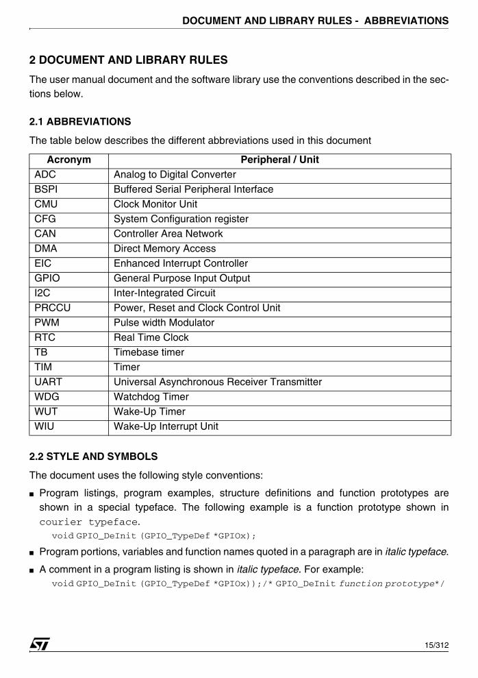
2.1 ABBREVIATIONS
The table below describes the different abbreviations used in this document
2.2 STYLE AND SYMBOLS
The document uses the following style conventions:
■ Program listings, program examples, structure definitions and function prototypes areshown in a special typeface. The following example is a function prototype shown incourier typeface.
void GPIO_DeInit (GPIO_TypeDef *GPIOx);
■ Program portions, variables and function names quoted in a paragraph are in italic typeface.
■ A comment in a program listing is shown in italic typeface. For example:void GPIO_DeInit (GPIO_TypeDef *GPIOx));/* GPIO_DeInit function prototype*/
Acronym Peripheral / UnitADC Analog to Digital Converter
BSPI Buffered Serial Peripheral Interface
CMU Clock Monitor Unit
CFG System Configuration registerCAN Controller Area Network
DMA Direct Memory Access
EIC Enhanced Interrupt Controller
GPIO General Purpose Input Output
I2C Inter-Integrated Circuit
PRCCU Power, Reset and Clock Control UnitPWM Pulse width Modulator
RTC Real Time Clock
TB Timebase timer
TIM Timer
UART Universal Asynchronous Receiver Transmitter
WDG Watchdog Timer
WUT Wake-Up TimerWIU Wake-Up Interrupt Unit
15/312
1
DOCUMENT AND LIBRARY RULES - NAMING CONVENTIONS
■ File paths and file names quoted in a paragraph are in italic typeface: The file 73x_prccu.cis located in the subdirectory library\src.
2.3 NAMING CONVENTIONS
The Software library uses the following naming conventions:
■ PPP is used to reference to any peripheral acronym, e.g. TIM. See the section above formore information on peripheral acronyms.
■ System and source/header file names are preceded by ‘73x_’, e.g. 73x_conf.h.
■ Constants used in one file are defined within this file. A constant used in more than one fileis defined in a header file. All constants use upper case characters.
■ Registers are considered as constants. Their names are in upper case letters and have inmost case the same acronyms as in the STR73x reference manual document.
■ Peripheral function names are preceded with the corresponding peripheral acronym inupper case followed by an underscore. The first letter in each word is upper case, e.g.UART_SetTimeOutValue. Only one underscore is allowed in a function name to separatethe peripheral acronym from the rest of the function name.
■ Functions for initializing PPP peripheral according to the specified parameters in thePPP_InitTypeDef are named PPP_Init, e.g. PRCCU_Init.
■ Functions for deinitializing PPP peripheral registers to their default reset values are namedPPP_DeInit, e.g. PRCCU_DeInit.
■ Functions for filling the PPP_InitTypeDef structure with the reset value of each member arenamed PPP_StructInit, e.g. PRCCU_StructInit.
■ Functions for checking whether the specified PPP flag is set or not are namedPPP_FlagStatus, e.g. TIM_FlagStatus.
■ Functions for clearing a PPP flag are named PPP_FlagClear, e.g. TIM_FlagClear.
■ Functions for enabling or disabling the specified PPP peripheral are named PPP_Cmd, e.g.ADC_Cmd.
■ Functions for enabling or disabling an interrupt source of the specified PPP peripheral arenamed PPP_ITConfig, e.g. PRCCU_ITConfig.
■ Functions for enabling or disabling the DMA interface of the specified PPP peripheral arenamed PPP_DMAConfig, e.g. TIM_DMAConfig.
■ Functions used to configure a peripheral function end with Config, e.g. PRCCU_VRConfig.
16/312
DOCUMENT AND LIBRARY RULES - CODING RULES
2.4 CODING RULES
The following rules are used in the Software Library.
■ 16 specific types are defined for variables whose type and size are fixed. These types aredefined in the file 73x_type.h:
typedef signed long s32;
typedef signed short s16;
typedef signed char s8;
typedef volatile signed long vs32;
typedef volatile signed short vs16;
typedef volatile signed char vs8;
typedef unsigned long u32;
typedef unsigned short u16;
typedef unsigned char u8;
typedef volatile unsigned long vu32;
typedef volatile unsigned short vu16;
typedef volatile unsigned char vu8;
typedef volatile unsigned long const vuc32; /* Read Only */
typedef volatile unsigned short const vuc16; /* Read Only */
typedef volatile unsigned char const vuc8; /* Read Only */
■ bool type is defined in the file 73x_type.h as:typedef enum
{
FALSE = 0,
TRUE =!FALSE
} bool;
■ FlagStatus type is defined in the file 73x_type.h. Two values can be assigned to thisvariable: SET or RESET.
typedef enum
{
RESET = 0,
SET =!RESET
} FlagStatus;
■ FunctionalState type is defined in the file 73x_type.h. Two values can be assigned to thisvariable: ENABLE or DISABLE.
typedef enum
{
DISABLE = 0,
ENABLE =!DISABLE
} FunctionalState;
17/312

DOCUMENT AND LIBRARY RULES - CODING RULES
■ ErrorStatus type is defined in the file 73x_type.h. Two values can be assigned to thisvariable: SUCCESS or ERROR.
typedef enum
{
ERROR = 0,
SUCCESS =!ERROR
} ErrorStatus;
■ Pointers to peripherals are used to access the peripheral control registers. Peripheralpointers point to data structures that represent the mapping of the peripheral controlregisters. A structure is defined for each peripheral in the file 73x_map.h. The examplebelow illustrates the ’GPIO register structure declaration:
/*------------------ General Purpose IO ports----------------------*/
typedef struct
{
vu16 PC0;
u16 EMPTY1;
vu16 PC1;
u16 EMPTY2;
vu16 PC2;
u16 EMPTY3;
vu16 PD;
} GPIO_TypeDef;
Register names are the register acronyms written in upper case for each peripheral. EMPTYi(i is an integer that indexes the reserved field) replaces a reserved field.
In some cases an enumeration is needed for a peripheral. This enumeration is calledPPP_Registers and is declared in the file 73x_ppp.h, e.g:
typedef enum
{
GPIOPC0 = 0x00,
GPIOPC1 = 0x04,
GPIOPC2 = 0x08,
GPIOPD = 0x0C,
} GPIO_Registers;
Peripherals are declared in 73x_map.h file. The following example shows the declaration ofthe GPIO peripheral:
#ifndef EXT
#Define EXT extern
#endif
...
/* GPIO2 Base Address definition*/
#define GPIO2_BASE (APB + 0x5420)
/* GPIO2 peripheral declaration*/
18/312
DOCUMENT AND LIBRARY RULES - CODING RULES
#ifdef DEBUG
EXT GPIO_TypeDef *GPIO2;
...
#else
#define GPIO2 ((GPIO_TypeDef *) GPIO2_BASE)
...
#endif
To enter debug mode you have to define the label DEBUG in the file 73x_conf.h. Debugmode allows you to see the contents of peripheral registers but it uses more memory space.In both cases GPIO2 is a pointer to the first address of GPIO2 port.
DEBUG variable is defined in the file 73x_conf.h as follows:#define DEBUG
DEBUG mode is initialized as follows in the 73x_lib.c file:#ifdef DEBUG
void debug(void)
{
...
#ifdef _GPIO2
GPIO2 = (GPIO_TypeDef *)GPIO2_BASE;
#endif /*_GPIO2*/
...
}
#endif /* DEBUG*/
To include the GPIO peripheral library in your application, define the label _GPIO and to ac-cess the GPIOn peripheral registers, define the label GPIOn, i.e to access the registers ofGPIO2 peripheral, _GPIO2 label must be defined in 73x_conf.h file. _GPIO and _GPIOn la-bels are defined in the file 73x_conf.h as follows:
#define _GPIO
#define _GPIO2
Each peripheral has several dedicated registers which contain different flags. Registers aredefined within a dedicated structure for each peripheral. Flag definition is adapted to each pe-ripheral case (defined in 73x_ppp.h file). Flags are defined as acronyms written in upper caseand prefixed by ‘PPP_Flag_’ prefix.
19/312
SOFTWARE LIBRARY - PACKAGE DESCRIPTION
3 SOFTWARE LIBRARY
3.1 PACKAGE DESCRIPTION
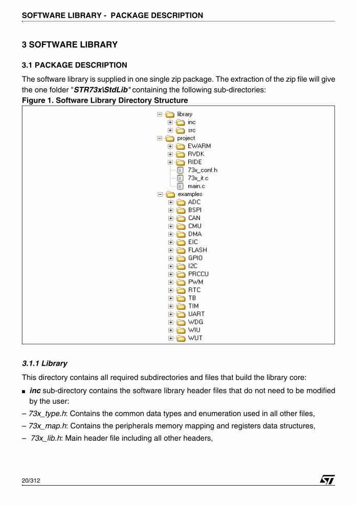
The software library is supplied in one single zip package. The extraction of the zip file will givethe one folder "STR73x\StdLib" containing the following sub-directories: Figure 1. Software Library Directory Structure
3.1.1 Library
This directory contains all required subdirectories and files that build the library core:
■ inc sub-directory contains the software library header files that do not need to be modifiedby the user:
– 73x_type.h: Contains the common data types and enumeration used in all other files,
– 73x_map.h: Contains the peripherals memory mapping and registers data structures,
– 73x_lib.h: Main header file including all other headers,
20/312
SOFTWARE LIBRARY - PACKAGE DESCRIPTION
– 73x_ppp.h (one header file per peripheral): contains the function prototypes, data structures and enumeration.
■ src sub-directory contains the software library source files that do not need to be modifiedby the user:
– 73x_ppp.c (one source file per peripheral): contains the function bodies of each peripheral.
Note : all library files are coded in Strict ANSI-C and are independent from any software tool-chain.
3.1.2 Project
This directory contains toolchain sub-directory ,a standard template project program that com-piles all library files and all the user modifiable files needed to create a new project :
– 73x_conf.h: The configuration header file with all peripherals defined by default,
– 73x_it.c: The source file containing the interrupt handlers (the function bodies are empty in this template),
– main.c: The main program body, that toggles for ever all GPIO4 port and print "Hello World" message in your software toolchain debugger console.
■ EWARM, RVDK, RIDE: For each toolchain usage, refer to Readme.txt file available in thesame sub-directory.
3.1.3 Examples
This directory contains for each peripheral sub-directory, the minimum set of files needed torun a typical example on how to use a peripheral:
– Readme.txt: a brief text file describing the example and how to make it work,
– 73x_conf.h: the header file to configure used peripherals and miscellaneous defines,
– 73x_it.c: the source file containing the interrupt handlers (the function bodies may be empty if not used)
– main.c: the example program.
Note : All examples are independent from any software tool chain.
21/312
SOFTWARE LIBRARY - FILE DESCRIPTION
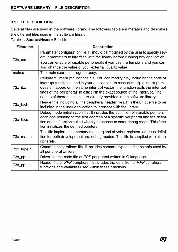
3.2 FILE DESCRIPTION
Several files are used in the software library. The following table enumerates and describesthe different files used in the software library.Table 1. Source/Header File List
Filename Description
73x_conf.h
Parameter configuration file. It should be modified by the user to specify sev-eral parameters to interface with the library before running any application.You can enable or disable peripherals if you use the template and you can also change the value of your external Quartz value.
main.c The main example program body.
73x_it.c
Peripheral interrupt functions file. You can modify it by including the code of interrupt functions used in your application. In case of multiple interrupt re-quests mapped on the same interrupt vector, the function polls the interrupt flags of the peripheral to establish the exact source of the interrupt. The names of these functions are already provided in the software library.
73x_lib.hHeader file including all the peripheral header files. It is the unique file to be included in the user application to interface with the library.
73x_lib.c
Debug mode initialization file. It includes the definition of variable pointers each one pointing to the first address of a specific peripheral and the defini-tion of one function called when you choose to enter debug mode. This func-tion initializes the defined pointers.
73x_map.hThis file implements memory mapping and physical registers address defini-tion for both development and debug modes. This file is supplied with all pe-ripherals.
73x_type.hCommon declarations file. It includes common types and constants used by all peripheral drivers.
73x_ppp.c Driver source code file of PPP peripheral written in C language.
73x_ppp.hHeader file of PPP peripheral. It includes the definition of PPP peripheral functions and variables used within these functions.
22/312
SOFTWARE LIBRARY - FILE DESCRIPTION
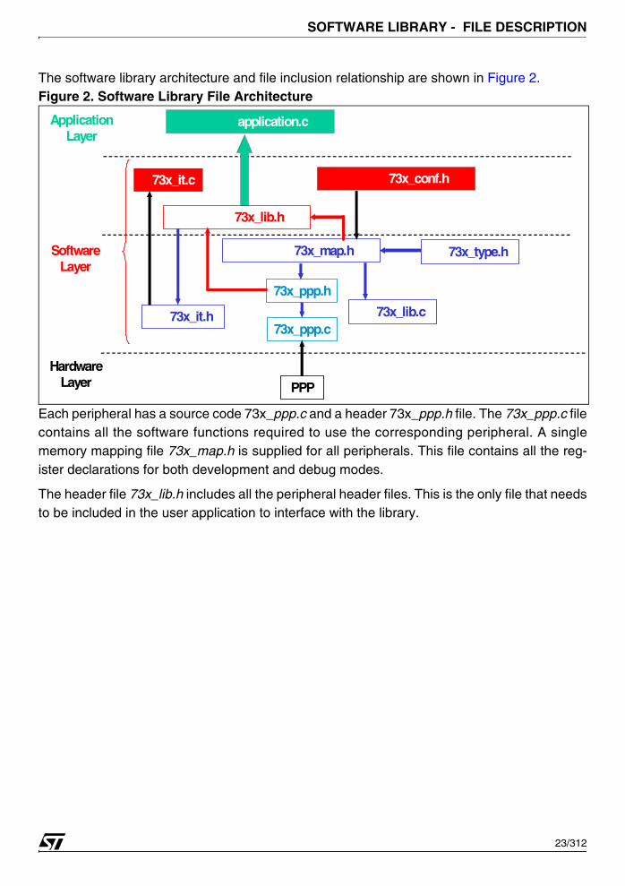
The software library architecture and file inclusion relationship are shown in Figure 2.Figure 2. Software Library File Architecture
Each peripheral has a source code 73x_ppp.c and a header 73x_ppp.h file. The 73x_ppp.c filecontains all the software functions required to use the corresponding peripheral. A singlememory mapping file 73x_map.h is supplied for all peripherals. This file contains all the reg-ister declarations for both development and debug modes.
The header file 73x_lib.h includes all the peripheral header files. This is the only file that needsto be included in the user application to interface with the library.
Application Layer
Software Layer
73x_ppp.c
PPP
Hardware Layer
73x_ppp.h
73x_map.h
73x_lib.c
73x_type.h
73x_lib.h
73x_it.h
73x_conf.h 73x_it.c
application.c
23/312
SOFTWARE LIBRARY - HOW TO USE THE LIBRARY
3.3 HOW TO USE THE LIBRARY
This section describes step-by-step how to configure and initialize a PPP peripheral.
1) In your main application file, declare a PPP_InitTypeDef structure, e.g: PPP_InitTypeDef PPP_InitStructure;
The PPP_InitStructure is a working variable located in data memory that allows you to ini-tialize one or more PPP instances.
2) Fill the PPP_InitStructure variable with the allowed values of the structure member.There are two ways of doing this:
■ Configuration of the whole structure: in this case you should proceed as follows:PPP_InitStructure.member1 = val1;
PPP_InitStructure.member2 = val2;
PPP_InitStructure.memberN = valN; /* where N is the number of
the structure members */
■ Configuration of a few members of a structure: in this case you should modify thePPP_InitStructure variable that has been already filled by a call to the PPP_StructInit(..)function. This ensures that the other members of the PPP_InitStructure variable haveappropriate values (in most case their reset values).
PPP_StructInit(&PPP_InitStructure);
PPP_InitStructure.memberX = valX;
PPP_InitStructure.memberY = valY; /* where X and Y are the only members that
you want to configure */
3) You have to initialize the PPP peripheral by calling the PPP_Init(..) function. PPP_Init(PPP, &PPP_InitStructure);
4) At this stage the PPP peripheral is initialized and can be enabled by making a call toPPP_Cmd(..) function.
PPP_Cmd(PPP, ENABLE);
To use the PPP peripheral, you can use a set of dedicated functions. These functions are spe-cific to the peripheral and for more details refer to section 4 on page 25.
Note: PPP_DeInit(..) function can be used to set all PPP peripheral registers to their resetvalues.
PPP_DeInit(PPP);
Note: If after peripheral configuration, you want to modify one or more peripheral settings youshould proceed as follows:
PPP_InitStucture.memberX = valX;
PPP_InitStructure.memberY = valY; /* where X and Y are the only members that
user wants to modify*/
PPP_Init(PPP, &PPP_InitStructure);
24/312
PERIPHERAL SOFTWARE - ANALOG TO DIGITAL CONVERTER (ADC)
4 PERIPHERAL SOFTWARE
This chapter describes in details each peripheral software library. The related functions arefully documented. An example of use of the function is given and some important considera-tions are also provided.
Functions are described in the format below:
4.1 ANALOG TO DIGITAL CONVERTER (ADC)
The ADC driver may be used to manage the ADC in its two modes of conversion: one-shot orscan and to generate a maskable interrupt when a sample is ready.
The first section describes the data structures used in the ADC software library. The secondone presents the software library functions.
4.1.1 Data structures
4.1.1.1 ADC Registers structure
The ADC peripheral register structure ADC_TypeDef is defined in the 73x_map.h file as fol-lows:
typedef struct
{
vu16 CLR0;
u16 EMPTY1;
vu16 CLR1;
u16 EMPTY2;
vu16 CLR2;
u16 EMPTY3;
vu16 CLR3;
u16 EMPTY4;
vu16 CLR4;
u16 EMPTY5;
vu16 TRA0;
u16 EMPTY6;
Function name The name of the peripheral function
Function prototype Prototype declarationBehavior Description Brief explanation of how the functions are executed
Input Parameter {x} Description of the input parameters
Output parameter {x} Description of the output parameters
Return Value Value returned by the function
Required Preconditions Requirements before to call the function
Called Functions Other library functions called by the functionSee also Related functions for reference
25/312
PERIPHERAL SOFTWARE - ANALOG TO DIGITAL CONVERTER (ADC)
vu16 TRA1;
u16 EMPTY7;
vu16 TRA2;
u16 EMPTY8;
vu16 TRA3;
u16 EMPTY9;
vu16 TRB0;
u16 EMPTY10;
vu16 TRB1;
u16 EMPTY11;
vu16 TRB2;
u16 EMPTY12;
vu16 TRB3;
u16 EMPTY13;
vu16 DMAR;
u16 EMPTY14[7];
vu16 DMAE;
u16 EMPTY15;
vu16 PBR;
u16 EMPTY16;
vu16 IMR;
u16 EMPTY17;
vuc16 D0;
u16 EMPTY18;
vuc16 D1;
u16 EMPTY19;
vuc16 D2;
u16 EMPTY20;
vuc16 D3;
u16 EMPTY21;
vuc16 D4;
u16 EMPTY22;
vuc16 D5;
u16 EMPTY23;
vuc16 D6;
u16 EMPTY24;
vuc16 D7;
u16 EMPTY25;
vuc16 D8;
u16 EMPTY26;
vuc16 D9;
u16 EMPTY27;
vuc16 D10;
u16 EMPTY28;
vuc16 D11;
26/312

PERIPHERAL SOFTWARE - ANALOG TO DIGITAL CONVERTER (ADC)
u16 EMPTY29;
vuc16 D12;
u16 EMPTY30;
vuc16 D13;
u16 EMPTY31;
vuc16 D14;
u16 EMPTY32;
vuc16 D15;
u16 EMPTY33;
} ADC_TypeDef;
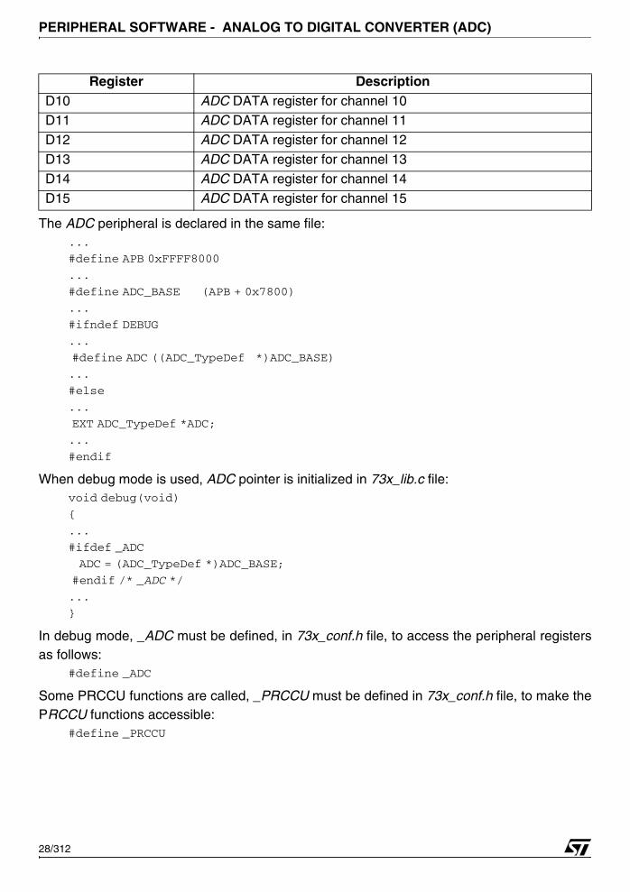
The following table presents the ADC registers:
Register DescriptionCLR0 ADC Control Logic register 0
CLR1 ADC Control Logic register 1
CLR2 ADC Control Logic register 2CLR3 ADC Control Logic register 3
CLR4 ADC Control Logic register 4
TRA0 ADC Threshold Detection Channel0 register A
TRA1 ADC Threshold Detection Channel1 register A
TRA2 ADC Threshold Detection Channel2 register A
TRA3 ADC Threshold Detection Channel3 register A
TRB0 ADC Threshold Detection Channel0 register BTRB1 ADC Threshold Detection Channel1 register B
TRB2 ADC Threshold Detection Channel2 register B
TRB3 ADC Threshold Detection Channel3 register B
DMAR ADC DMA register
DMAE ADC DMA Enable register
PBR ADC Pending Bit registerIMR ADC Interrupt Mask Register
D0 ADC DATA register for channel 0
D1 ADC DATA register for channel 1
D2 ADC DATA register for channel 2
D3 ADC DATA register for channel 3
D4 ADC DATA register for channel 4D5 ADC DATA register for channel 5
D6 ADC DATA register for channel 6
D7 ADC DATA register for channel 7
D8 ADC DATA register for channel 8
D9 ADC DATA register for channel 9
27/312
PERIPHERAL SOFTWARE - ANALOG TO DIGITAL CONVERTER (ADC)
The ADC peripheral is declared in the same file:...
#define APB 0xFFFF8000
...
#define ADC_BASE (APB + 0x7800)
...
#ifndef DEBUG
...
#define ADC ((ADC_TypeDef *)ADC_BASE)
...
#else
...
EXT ADC_TypeDef *ADC;
...
#endif
When debug mode is used, ADC pointer is initialized in 73x_lib.c file:void debug(void)
{
...
#ifdef _ADC
ADC = (ADC_TypeDef *)ADC_BASE;
#endif /* _ADC */
...
}
In debug mode, _ADC must be defined, in 73x_conf.h file, to access the peripheral registersas follows:
#define _ADC
Some PRCCU functions are called, _PRCCU must be defined in 73x_conf.h file, to make thePRCCU functions accessible:
#define _PRCCU
D10 ADC DATA register for channel 10D11 ADC DATA register for channel 11
D12 ADC DATA register for channel 12
D13 ADC DATA register for channel 13
D14 ADC DATA register for channel 14
D15 ADC DATA register for channel 15
Register Description
28/312
PERIPHERAL SOFTWARE - ANALOG TO DIGITAL CONVERTER (ADC)
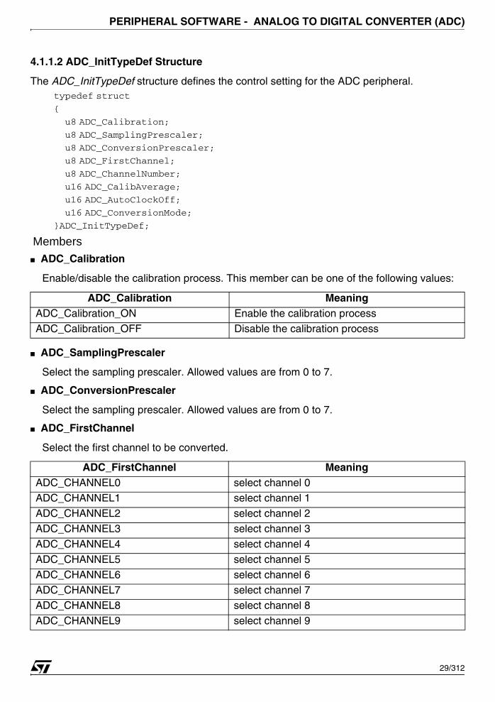
4.1.1.2 ADC_InitTypeDef Structure
The ADC_InitTypeDef structure defines the control setting for the ADC peripheral.typedef struct
{
u8 ADC_Calibration;
u8 ADC_SamplingPrescaler;
u8 ADC_ConversionPrescaler;
u8 ADC_FirstChannel;
u8 ADC_ChannelNumber;
u16 ADC_CalibAverage;
u16 ADC_AutoClockOff;
u16 ADC_ConversionMode;
}ADC_InitTypeDef;
Members■ ADC_Calibration
Enable/disable the calibration process. This member can be one of the following values:
■ ADC_SamplingPrescaler
Select the sampling prescaler. Allowed values are from 0 to 7.
■ ADC_ConversionPrescaler
Select the sampling prescaler. Allowed values are from 0 to 7.
■ ADC_FirstChannel
Select the first channel to be converted.
ADC_Calibration MeaningADC_Calibration_ON Enable the calibration process
ADC_Calibration_OFF Disable the calibration process
ADC_FirstChannel MeaningADC_CHANNEL0 select channel 0ADC_CHANNEL1 select channel 1
ADC_CHANNEL2 select channel 2
ADC_CHANNEL3 select channel 3
ADC_CHANNEL4 select channel 4
ADC_CHANNEL5 select channel 5
ADC_CHANNEL6 select channel 6ADC_CHANNEL7 select channel 7
ADC_CHANNEL8 select channel 8
ADC_CHANNEL9 select channel 9
29/312
PERIPHERAL SOFTWARE - ANALOG TO DIGITAL CONVERTER (ADC)
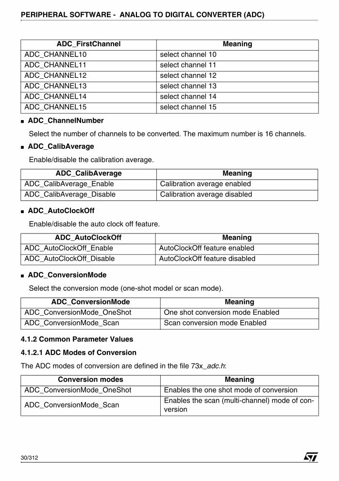
■ ADC_ChannelNumber
Select the number of channels to be converted. The maximum number is 16 channels.
■ ADC_CalibAverage
Enable/disable the calibration average.
■ ADC_AutoClockOff
Enable/disable the auto clock off feature.
■ ADC_ConversionMode
Select the conversion mode (one-shot model or scan mode).
4.1.2 Common Parameter Values
4.1.2.1 ADC Modes of Conversion
The ADC modes of conversion are defined in the file 73x_adc.h:
ADC_CHANNEL10 select channel 10ADC_CHANNEL11 select channel 11
ADC_CHANNEL12 select channel 12
ADC_CHANNEL13 select channel 13
ADC_CHANNEL14 select channel 14
ADC_CHANNEL15 select channel 15
ADC_CalibAverage MeaningADC_CalibAverage_Enable Calibration average enabled
ADC_CalibAverage_Disable Calibration average disabled
ADC_AutoClockOff MeaningADC_AutoClockOff_Enable AutoClockOff feature enabled
ADC_AutoClockOff_Disable AutoClockOff feature disabled
ADC_ConversionMode MeaningADC_ConversionMode_OneShot One shot conversion mode EnabledADC_ConversionMode_Scan Scan conversion mode Enabled
Conversion modes MeaningADC_ConversionMode_OneShot Enables the one shot mode of conversion
ADC_ConversionMode_ScanEnables the scan (multi-channel) mode of con-version
ADC_FirstChannel Meaning
30/312
PERIPHERAL SOFTWARE - ANALOG TO DIGITAL CONVERTER (ADC)
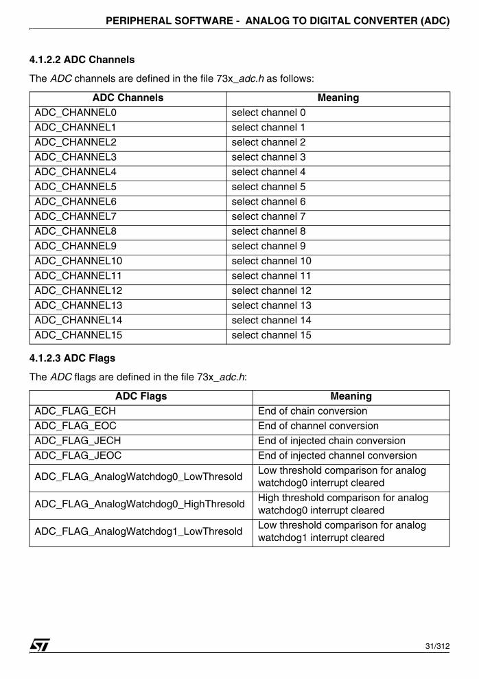
4.1.2.2 ADC Channels
The ADC channels are defined in the file 73x_adc.h as follows:
4.1.2.3 ADC Flags
The ADC flags are defined in the file 73x_adc.h:
ADC Channels MeaningADC_CHANNEL0 select channel 0ADC_CHANNEL1 select channel 1
ADC_CHANNEL2 select channel 2
ADC_CHANNEL3 select channel 3
ADC_CHANNEL4 select channel 4
ADC_CHANNEL5 select channel 5
ADC_CHANNEL6 select channel 6ADC_CHANNEL7 select channel 7
ADC_CHANNEL8 select channel 8
ADC_CHANNEL9 select channel 9
ADC_CHANNEL10 select channel 10
ADC_CHANNEL11 select channel 11
ADC_CHANNEL12 select channel 12
ADC_CHANNEL13 select channel 13ADC_CHANNEL14 select channel 14
ADC_CHANNEL15 select channel 15
ADC Flags MeaningADC_FLAG_ECH End of chain conversion
ADC_FLAG_EOC End of channel conversionADC_FLAG_JECH End of injected chain conversion
ADC_FLAG_JEOC End of injected channel conversion
ADC_FLAG_AnalogWatchdog0_LowThresoldLow threshold comparison for analog watchdog0 interrupt cleared
ADC_FLAG_AnalogWatchdog0_HighThresoldHigh threshold comparison for analog watchdog0 interrupt cleared
ADC_FLAG_AnalogWatchdog1_LowThresoldLow threshold comparison for analog watchdog1 interrupt cleared
31/312
PERIPHERAL SOFTWARE - ANALOG TO DIGITAL CONVERTER (ADC)
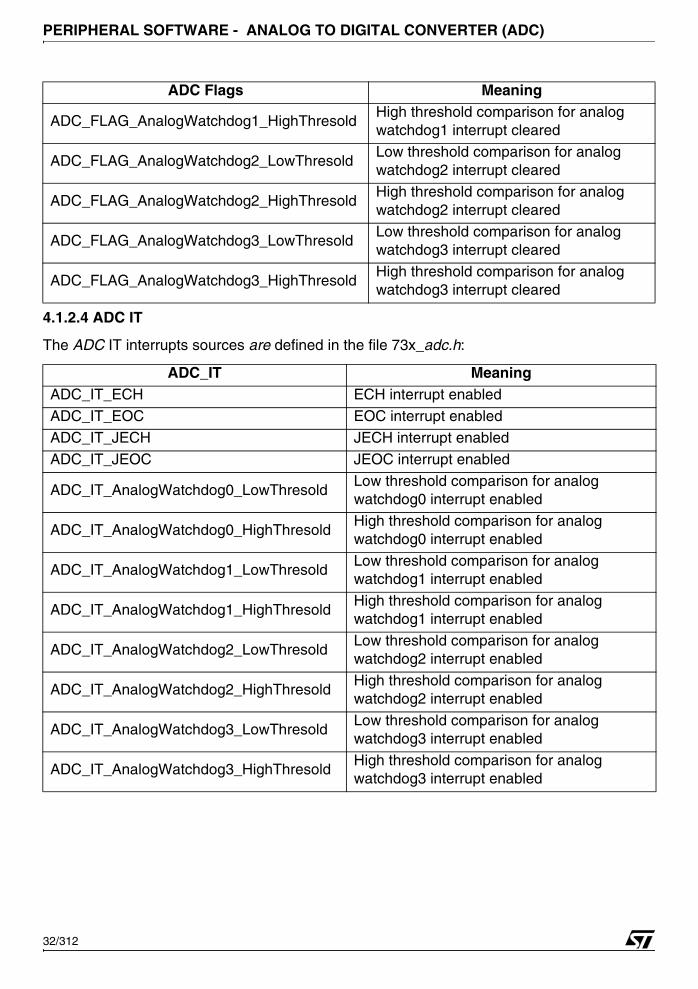
4.1.2.4 ADC IT
The ADC IT interrupts sources are defined in the file 73x_adc.h:
ADC_FLAG_AnalogWatchdog1_HighThresoldHigh threshold comparison for analog watchdog1 interrupt cleared
ADC_FLAG_AnalogWatchdog2_LowThresoldLow threshold comparison for analog watchdog2 interrupt cleared
ADC_FLAG_AnalogWatchdog2_HighThresoldHigh threshold comparison for analog watchdog2 interrupt cleared
ADC_FLAG_AnalogWatchdog3_LowThresoldLow threshold comparison for analog watchdog3 interrupt cleared
ADC_FLAG_AnalogWatchdog3_HighThresoldHigh threshold comparison for analog watchdog3 interrupt cleared
ADC_IT MeaningADC_IT_ECH ECH interrupt enabled
ADC_IT_EOC EOC interrupt enabled
ADC_IT_JECH JECH interrupt enabled
ADC_IT_JEOC JEOC interrupt enabled
ADC_IT_AnalogWatchdog0_LowThresoldLow threshold comparison for analog watchdog0 interrupt enabled
ADC_IT_AnalogWatchdog0_HighThresoldHigh threshold comparison for analog watchdog0 interrupt enabled
ADC_IT_AnalogWatchdog1_LowThresoldLow threshold comparison for analog watchdog1 interrupt enabled
ADC_IT_AnalogWatchdog1_HighThresoldHigh threshold comparison for analog watchdog1 interrupt enabled
ADC_IT_AnalogWatchdog2_LowThresoldLow threshold comparison for analog watchdog2 interrupt enabled
ADC_IT_AnalogWatchdog2_HighThresoldHigh threshold comparison for analog watchdog2 interrupt enabled
ADC_IT_AnalogWatchdog3_LowThresoldLow threshold comparison for analog watchdog3 interrupt enabled
ADC_IT_AnalogWatchdog3_HighThresoldHigh threshold comparison for analog watchdog3 interrupt enabled
ADC Flags Meaning
32/312
PERIPHERAL SOFTWARE - ANALOG TO DIGITAL CONVERTER (ADC)
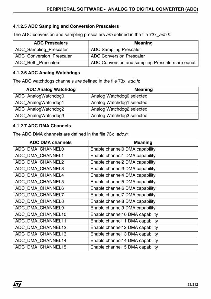
4.1.2.5 ADC Sampling and Conversion Prescalers
The ADC conversion and sampling prescalers are defined in the file 73x_adc.h:
4.1.2.6 ADC Analog Watchdogs
The ADC watchdogs channels are defined in the file 73x_adc.h:
4.1.2.7 ADC DMA Channels
The ADC DMA channels are defined in the file 73x_adc.h:
ADC Prescalers MeaningADC_Sampling_Prescaler ADC Sampling PrescalerADC_Conversion_Prescaler ADC Conversion Prescaler
ADC_Both_Prescalers ADC Conversion and sampling Prescalers are equal
ADC Analog Watchdog MeaningADC_AnalogWatchdog0 Analog Watchdog0 selected
ADC_AnalogWatchdog1 Analog Watchdog1 selectedADC_AnalogWatchdog2 Analog Watchdog2 selected
ADC_AnalogWatchdog3 Analog Watchdog3 selected
ADC DMA channels MeaningADC_DMA_CHANNEL0 Enable channel0 DMA capability
ADC_DMA_CHANNEL1 Enable channel1 DMA capabilityADC_DMA_CHANNEL2 Enable channel2 DMA capability
ADC_DMA_CHANNEL3 Enable channel3 DMA capability
ADC_DMA_CHANNEL4 Enable channel4 DMA capability
ADC_DMA_CHANNEL5 Enable channel5 DMA capability
ADC_DMA_CHANNEL6 Enable channel6 DMA capability
ADC_DMA_CHANNEL7 Enable channel7 DMA capability
ADC_DMA_CHANNEL8 Enable channel8 DMA capabilityADC_DMA_CHANNEL9 Enable channel9 DMA capability
ADC_DMA_CHANNEL10 Enable channel10 DMA capability
ADC_DMA_CHANNEL11 Enable channel11 DMA capability
ADC_DMA_CHANNEL12 Enable channel12 DMA capability
ADC_DMA_CHANNEL13 Enable channel13 DMA capability
ADC_DMA_CHANNEL14 Enable channel14 DMA capabilityADC_DMA_CHANNEL15 Enable channel15 DMA capability
33/312
PERIPHERAL SOFTWARE - ANALOG TO DIGITAL CONVERTER (ADC)
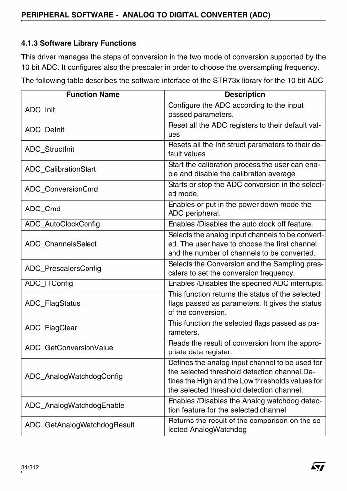
4.1.3 Software Library Functions
This driver manages the steps of conversion in the two mode of conversion supported by the10 bit ADC. It configures also the prescaler in order to choose the oversampling frequency.
The following table describes the software interface of the STR73x library for the 10 bit ADC
Function Name Description
ADC_InitConfigure the ADC according to the input passed parameters.
ADC_DeInitReset all the ADC registers to their default val-ues
ADC_StructInitResets all the Init struct parameters to their de-fault values
ADC_CalibrationStartStart the calibration process.the user can ena-ble and disable the calibration average
ADC_ConversionCmdStarts or stop the ADC conversion in the select-ed mode.
ADC_CmdEnables or put in the power down mode the ADC peripheral.
ADC_AutoClockConfig Enables /Disables the auto clock off feature.
ADC_ChannelsSelectSelects the analog input channels to be convert-ed. The user have to choose the first channel and the number of channels to be converted.
ADC_PrescalersConfigSelects the Conversion and the Sampling pres-calers to set the conversion frequency.
ADC_ITConfig Enables /Disables the specified ADC interrupts.
ADC_FlagStatusThis function returns the status of the selected flags passed as parameters. It gives the status of the conversion.
ADC_FlagClearThis function the selected flags passed as pa-rameters.
ADC_GetConversionValueReads the result of conversion from the appro-priate data register.
ADC_AnalogWatchdogConfig
Defines the analog input channel to be used for the selected threshold detection channel.De-fines the High and the Low thresholds values for the selected threshold detection channel.
ADC_AnalogWatchdogEnableEnables /Disables the Analog watchdog detec-tion feature for the selected channel
ADC_GetAnalogWatchdogResultReturns the result of the comparison on the se-lected AnalogWatchdog
34/312
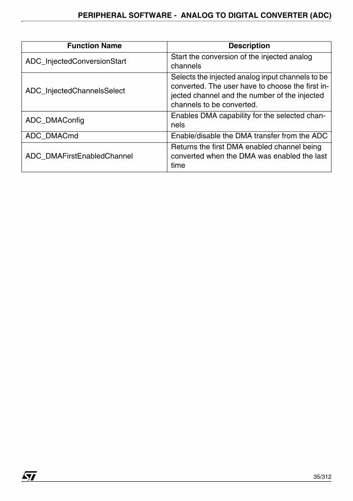
PERIPHERAL SOFTWARE - ANALOG TO DIGITAL CONVERTER (ADC)
ADC_InjectedConversionStartStart the conversion of the injected analog channels
ADC_InjectedChannelsSelect
Selects the injected analog input channels to be converted. The user have to choose the first in-jected channel and the number of the injected channels to be converted.
ADC_DMAConfigEnables DMA capability for the selected chan-nels
ADC_DMACmd Enable/disable the DMA transfer from the ADC
ADC_DMAFirstEnabledChannelReturns the first DMA enabled channel being converted when the DMA was enabled the last time
Function Name Description
35/312
PERIPHERAL SOFTWARE - ANALOG TO DIGITAL CONVERTER (ADC)
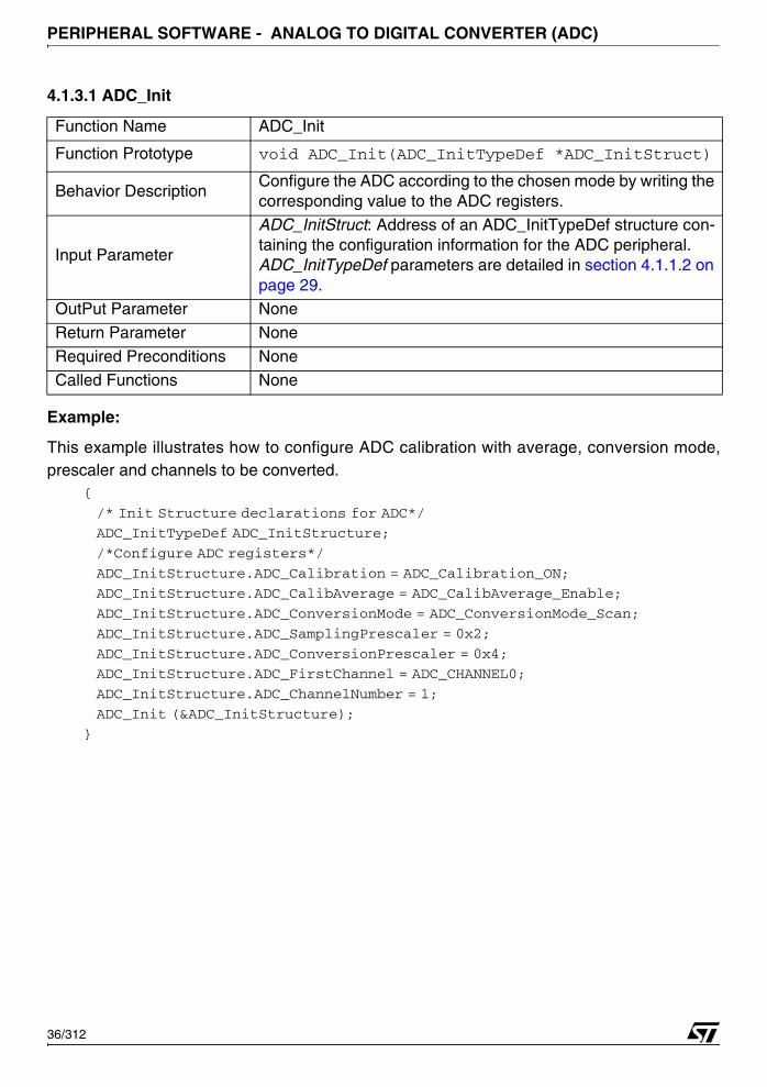
4.1.3.1 ADC_Init
Example:
This example illustrates how to configure ADC calibration with average, conversion mode,prescaler and channels to be converted.
{
/* Init Structure declarations for ADC*/
ADC_InitTypeDef ADC_InitStructure;
/*Configure ADC registers*/
ADC_InitStructure.ADC_Calibration = ADC_Calibration_ON;
ADC_InitStructure.ADC_CalibAverage = ADC_CalibAverage_Enable;
ADC_InitStructure.ADC_ConversionMode = ADC_ConversionMode_Scan;
ADC_InitStructure.ADC_SamplingPrescaler = 0x2;
ADC_InitStructure.ADC_ConversionPrescaler = 0x4;
ADC_InitStructure.ADC_FirstChannel = ADC_CHANNEL0;
ADC_InitStructure.ADC_ChannelNumber = 1;
ADC_Init (&ADC_InitStructure);
}
Function Name ADC_Init
Function Prototype void ADC_Init(ADC_InitTypeDef *ADC_InitStruct)
Behavior Description Configure the ADC according to the chosen mode by writing the corresponding value to the ADC registers.
Input Parameter
ADC_InitStruct: Address of an ADC_InitTypeDef structure con-taining the configuration information for the ADC peripheral. ADC_InitTypeDef parameters are detailed in section 4.1.1.2 on page 29.
OutPut Parameter None
Return Parameter None
Required Preconditions None
Called Functions None
36/312

PERIPHERAL SOFTWARE - ANALOG TO DIGITAL CONVERTER (ADC)
4.1.3.2 ADC_DeInit
Example:
This example illustrates how to deinitialize ADC registers.{
ADC_DeInit (); /*Deinitialize ADC registers*/
}
4.1.3.3 ADC_StructInit
Example:
This example illustrates how to initialize ADC init structure.{
/* Init Structure declaration for ADC */
ADC_InitTypeDef ADC_InitStructure;
/* Initialize ADC structure*/
ADC_StructInit (&ADC_InitStructure);
}
Function Name ADC_DeInit
Function Prototype void ADC_DeInit (void)
Behavior Description Reset all the ADC registers to their default values
Input Parameter None
OutPut Parameter None
Return Parameter NoneRequired Preconditions None
Called Functions None
Function Name ADC_StructInit
Function Prototypevoid ADC_StructInit(ADC_InitTypeDef *ADC_InitStruct)
Behavior Description Resets all the Init struct parameters to their default values
Input Parameter ADC_InitStruct: Address of an ADC_InitTypeDef structure. ADC_InitTypeDef parameters are detailed in Section 4.1.1.2.
OutPut Parameter None
Return Parameter None
Required Preconditions None
Called Functions None
37/312
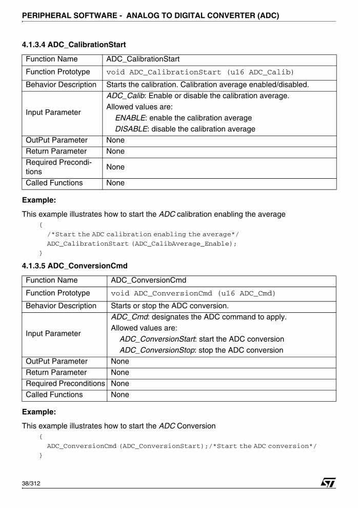
PERIPHERAL SOFTWARE - ANALOG TO DIGITAL CONVERTER (ADC)
4.1.3.4 ADC_CalibrationStart
Example:
This example illustrates how to start the ADC calibration enabling the average{
/*Start the ADC calibration enabling the average*/
ADC_CalibrationStart (ADC_CalibAverage_Enable);
}
4.1.3.5 ADC_ConversionCmd
Example:
This example illustrates how to start the ADC Conversion{
ADC_ConversionCmd (ADC_ConversionStart);/*Start the ADC conversion*/
}
Function Name ADC_CalibrationStart
Function Prototype void ADC_CalibrationStart (u16 ADC_Calib)
Behavior Description Starts the calibration. Calibration average enabled/disabled.
Input Parameter
ADC_Calib: Enable or disable the calibration average.
Allowed values are:
ENABLE: enable the calibration average DISABLE: disable the calibration average
OutPut Parameter None
Return Parameter None
Required Precondi-tions
None
Called Functions None
Function Name ADC_ConversionCmd
Function Prototype void ADC_ConversionCmd (u16 ADC_Cmd)
Behavior Description Starts or stop the ADC conversion.
Input Parameter
ADC_Cmd: designates the ADC command to apply.
Allowed values are:
ADC_ConversionStart: start the ADC conversion ADC_ConversionStop: stop the ADC conversion
OutPut Parameter None
Return Parameter None
Required Preconditions None
Called Functions None
38/312
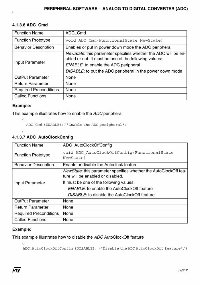
PERIPHERAL SOFTWARE - ANALOG TO DIGITAL CONVERTER (ADC)
4.1.3.6 ADC_Cmd
Example:
This example illustrates how to enable the ADC peripheral{
ADC_Cmd (ENABLE);/*Enable the ADC peripheral*/
}
4.1.3.7 ADC_AutoClockConfig
Example:
This example illustrates how to disable the ADC AutoClockOff feature{
ADC_AutoClockOffConfig (DISABLE); /*Disable the ADC AutoClockOff feature*/}
Function Name ADC_Cmd
Function Prototype void ADC_Cmd(FunctionalState NewState)
Behavior Description Enables or put in power down mode the ADC peripheral
Input Parameter
NewState: this parameter specifies whether the ADC will be en-abled or not. It must be one of the following values:
ENABLE: to enable the ADC peripheral
DISABLE: to put the ADC peripheral in the power down mode
OutPut Parameter NoneReturn Parameter None
Required Preconditions None
Called Functions None
Function Name ADC_AutoClockOffConfig
Function Prototypevoid ADC_AutoClockOffConfig(FunctionalState NewState)
Behavior Description Enable or disable the Autoclock feature.
Input Parameter
NewState: this parameter specifies whether the AutoClockOff fea-ture will be enabled or disabled.
It must be one of the following values:
ENABLE: to enable the AutoClockOff feature
DISABLE: to disable the AutoClockOff feature
OutPut Parameter NoneReturn Parameter None
Required Preconditions None
Called Functions None
39/312
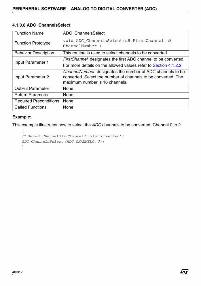
PERIPHERAL SOFTWARE - ANALOG TO DIGITAL CONVERTER (ADC)
4.1.3.8 ADC_ChannelsSelect
Example:
This example illustrates how to select the ADC channels to be converted: Channel 0 to 2{
/* Select Channel0 to Channel2 to be converted*/
ADC_ChannelsSelect (ADC_CHANNEL0, 3);
}
Function Name ADC_ChannelsSelect
Function Prototypevoid ADC_ChannelsSelect(u8 FirstChannel,u8 ChannelNumber )
Behavior Description This routine is used to select channels to be converted.
Input Parameter 1FirstChannel: designates the first ADC channel to be converted.
For more details on the allowed values refer to Section 4.1.2.2.
Input Parameter 2ChannelNumber: designates the number of ADC channels to be converted. Select the number of channels to be converted. The maximum number is 16 channels.
OutPut Parameter None
Return Parameter None
Required Preconditions NoneCalled Functions None
40/312

PERIPHERAL SOFTWARE - ANALOG TO DIGITAL CONVERTER (ADC)
4.1.3.9 ADC_PrescalersConfig
Example:
This example illustrates how to configure sampling and conversion ADC prescalers{
/* Set ADC Sampling prescaler to 0x2 */
ADC_PrescalersConfig (ADC_Sampling_Prescaler, 0x2);
/* Set ADC Conversion prescaler to 0x4 */
ADC_PrescalersConfig (ADC_Conversion_Prescaler, 0x4);
}
Function Name ADC_PrescalersConfig
Function Prototypevoid ADC_PrescalersConfig(u8 ADC_Selection, u8 ADC_Prescaler)
Behavior Description Set the desired prescaler value
Input Parameter 1
ADC_Selection: This parameter specifies the Prescaler to be set with passed prescaler value. Allowed values are:
ADC_Both_Prescalers: Both Sampling and conversion Prescaler
ADC_Sampling_Prescaler: Sampling conversion
ADC_Conversion_Prescaler: Conversion conversion
Input Parameter 2ADC_Prescaler: Designates the prescaler value to setSelect a prescaler value from 0 to 7.
OutPut Parameter None
Return Parameter None
Required Preconditions None
Called Functions None
41/312
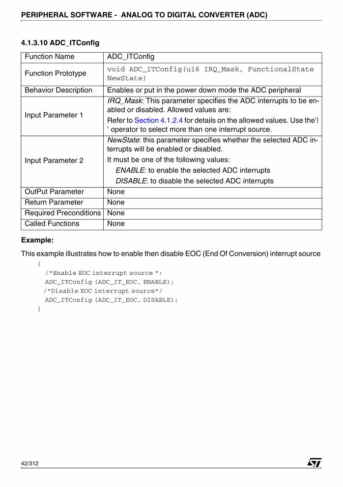
PERIPHERAL SOFTWARE - ANALOG TO DIGITAL CONVERTER (ADC)
4.1.3.10 ADC_ITConfig
Example:
This example illustrates how to enable then disable EOC (End Of Conversion) interrupt source {
/*Enable EOC interrupt source *:
ADC_ITConfig (ADC_IT_EOC, ENABLE);
/*Disable EOC interrupt source*/
ADC_ITConfig (ADC_IT_EOC, DISABLE);
}
Function Name ADC_ITConfig
Function Prototypevoid ADC_ITConfig(u16 IRQ_Mask, FunctionalState NewState)
Behavior Description Enables or put in the power down mode the ADC peripheral
Input Parameter 1
IRQ_Mask: This parameter specifies the ADC interrupts to be en-abled or disabled. Allowed values are:
Refer to Section 4.1.2.4 for details on the allowed values. Use the’| ’ operator to select more than one interrupt source.
Input Parameter 2
NewState: this parameter specifies whether the selected ADC in-terrupts will be enabled or disabled.
It must be one of the following values:
ENABLE: to enable the selected ADC interrupts
DISABLE: to disable the selected ADC interrupts
OutPut Parameter NoneReturn Parameter None
Required Preconditions None
Called Functions None
42/312

PERIPHERAL SOFTWARE - ANALOG TO DIGITAL CONVERTER (ADC)
4.1.3.11 ADC_FlagStatus
Example:
This example illustrates how to read the EOC flag status{
FlagStatus EOC_Flag; /* EOC_Flag declaration*/
EOC_Flag = ADC_FlagStatus(ADC_FLAG_EOC);/* Read EOC flag status */
}
4.1.3.12 ADC_FlagClear
Example:
This example illustrates how to clear the ADC_FLAG_AnalogWatchdog0_LowThreshold flag {
/* Clear the ADC_FLAG_AnalogWatchdog0_LowThreshold flag*:
ADC_FlagClear(ADC_FLAG_AnalogWatchdog0_LowThreshold);
}
Function Name ADC_FlagStatus
Function Prototype FlagStatus ADC_FlagStatus (u16 ADC_Flag)
Behavior Description This routine is used to check the RTC flags.
Input Parameter 1ADC_Flag: designates the ADC flag to check.
Refer to Section 4.1.2.3 for more details on the allowed values of this parameter.
OutPut Parameter None
Return ParameterOne of the FlagStatus enum type, the available values are: SET: if the flag to check is set (equal to 1).
RESET: if the flag to check is reset.
Required Preconditions None
Called Functions None
Function Name ADC_FlagClear
Function Prototype void ADC_FlagClear (u16 ADC_Flag)
Behavior Description This routine is used to check the RTC flags.
Input Parameter 1ADC_Flag: designates the ADC flag to check.
Refer to Section 4.1.2.3 for more details on the allowed values of this parameter.
OutPut Parameter None
Return Parameter NoneRequired Preconditions None
Called Functions None
43/312
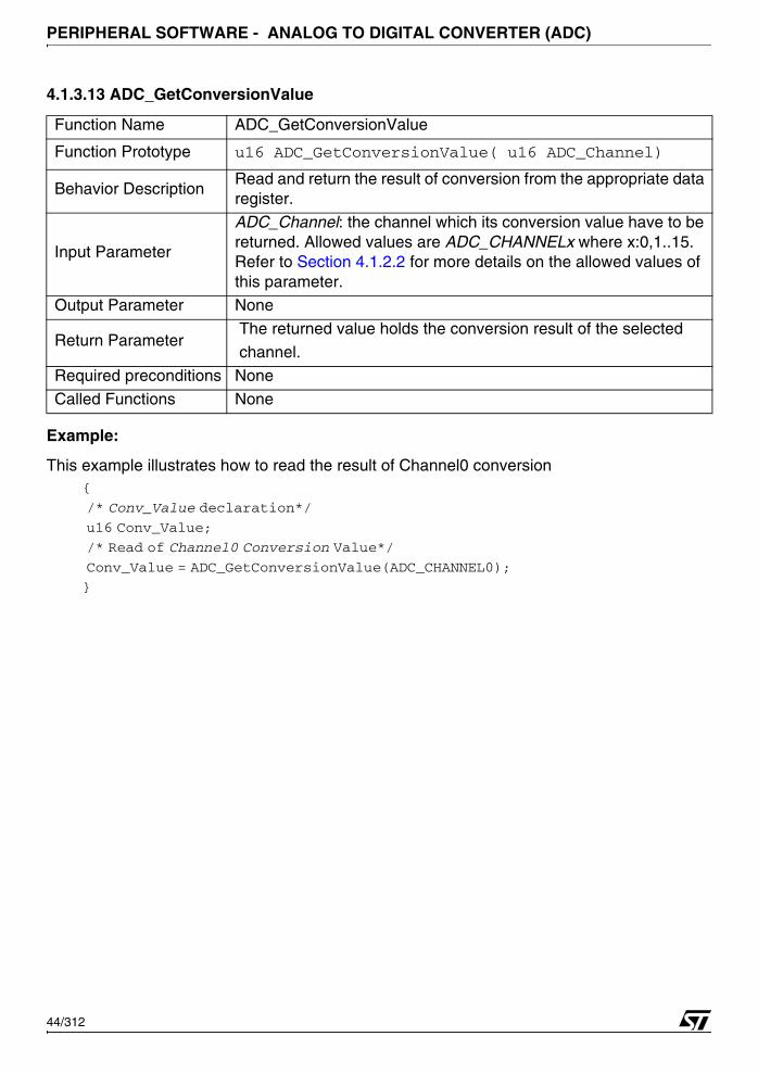
PERIPHERAL SOFTWARE - ANALOG TO DIGITAL CONVERTER (ADC)
4.1.3.13 ADC_GetConversionValue
Example:
This example illustrates how to read the result of Channel0 conversion{
/* Conv_Value declaration*/
u16 Conv_Value;
/* Read of Channel0 Conversion Value*/
Conv_Value = ADC_GetConversionValue(ADC_CHANNEL0);
}
Function Name ADC_GetConversionValue
Function Prototype u16 ADC_GetConversionValue( u16 ADC_Channel)
Behavior Description Read and return the result of conversion from the appropriate data register.
Input Parameter
ADC_Channel: the channel which its conversion value have to be returned. Allowed values are ADC_CHANNELx where x:0,1..15. Refer to Section 4.1.2.2 for more details on the allowed values of this parameter.
Output Parameter None
Return Parameter The returned value holds the conversion result of the selected
channel.
Required preconditions None
Called Functions None
44/312

PERIPHERAL SOFTWARE - ANALOG TO DIGITAL CONVERTER (ADC)
4.1.3.14 ADC_AnalogWatchdogConfig
Example:
This example illustrates how to configure Analogwatchdog0 to channel4 with 0x55 as lowthreshold and 0x2FF as high threshold
{
/* Configure AnalogWatchdog0*/
ADC_AnalogWatchdogConfig (ADC_AnalogWatchdog0, ADC_CHANNEL4, 0x55, 2FF);
}
Function Name ADC_AnalogWatchdogConfig
Function Prototypevoid ADC_AnalogWatchdogConfig(u16 ADC_Watchdog, u8 ADC_Channel, u16 LowThreshold, u16 HighThreshold )
Behavior Description Enables or put in power down mode the ADC peripheral
Input Parameter 1
ADC_Watchdog: this parameter specifies the analog watchdog channel which will be affected to the desired converted channel.
Refer to Section 4.1.2.6 for more details on the allowed values of this parameter.
Input Parameter 2ADC_Channel: this parameter specifies the channel linked to the threshold detection selected in the first parameter.
Refer to Section 4.1.2.2 for more details on the allowed values.
Input Parameter 3 HighThreshold: 10bit value selected by the user
Input Parameter 4 LowThreshold: 10bit value selected by the user
OutPut Parameter None
Return Parameter NoneRequired Preconditions None
Called Functions None
45/312
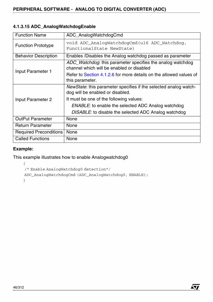
PERIPHERAL SOFTWARE - ANALOG TO DIGITAL CONVERTER (ADC)
4.1.3.15 ADC_AnalogWatchdogEnable
Example:
This example illustrates how to enable Analogwatchdog0 {
/* Enable AnalogWatchdog0 detection*/
ADC_AnalogWatchdogCmd (ADC_AnalogWatchdog0, ENABLE);
}
Function Name ADC_AnalogWatchdogCmd
Function Prototypevoid ADC_AnalogWatchdogCmd(u16 ADC_Watchdog, FunctionalState NewState)
Behavior Description Enables /Disables the Analog watchdog passed as parameter
Input Parameter 1
ADC_Watchdog: this parameter specifies the analog watchdog channel which will be enabled or disabled
Refer to Section 4.1.2.6 for more details on the allowed values of this parameter.
Input Parameter 2
NewState: this parameter specifies if the selected analog watch-dog will be enabled or disabled.
It must be one of the following values:
ENABLE: to enable the selected ADC Analog watchdog
DISABLE: to disable the selected ADC Analog watchdog
OutPut Parameter NoneReturn Parameter None
Required Preconditions None
Called Functions None
46/312

PERIPHERAL SOFTWARE - ANALOG TO DIGITAL CONVERTER (ADC)
4.1.3.16 ADC_GetAnalogWatchdogResult
Example:
This example illustrates how to read the comparison result of the Analog Watchdog0 detection{
u16 Comp_Result; /*Comp_Result declaration */
Comp_Result = ADC_GetAnanlogWatchdogResult (ADC_AnanlogWatchdog0);
}
4.1.3.17 ADC_InjectedConversionStart
Example:
This example illustrates how to start the ADC injected conversion{
ADC_InjectedConversionStart (); /*Start the ADC injected conversion*/
}
Function Name ADC_GetAnalogWatchdogResult
Function Prototypeu16 ADC_GetAnalogWatchdogResult ( u16 ADC_Watchdog)
Behavior DescriptionReturn the result of the comparison on the selected Analog watch-dog passed as parameter
Input Parameter 1
ADC_Watchdog: this parameter specifies the analog watchdog channel which its comparison result will be returned.
Refer to Section 4.1.2.6 for more details on the allowed values of this parameter.
OutPut Parameter None
Return Parameter None
Required Preconditions None
Called Functions None
Function Name ADC_InjectedConversionStart
Function Prototype void ADC_InjectedConversionStart (void)
Behavior DescriptionStart by software the configured injected analog channels to be converted.
Input Parameter None
OutPut Parameter None
Return ParameterThe returned value holds the comparison result of the selected analog watchdog.
Required Preconditions NoneCalled Functions None
47/312
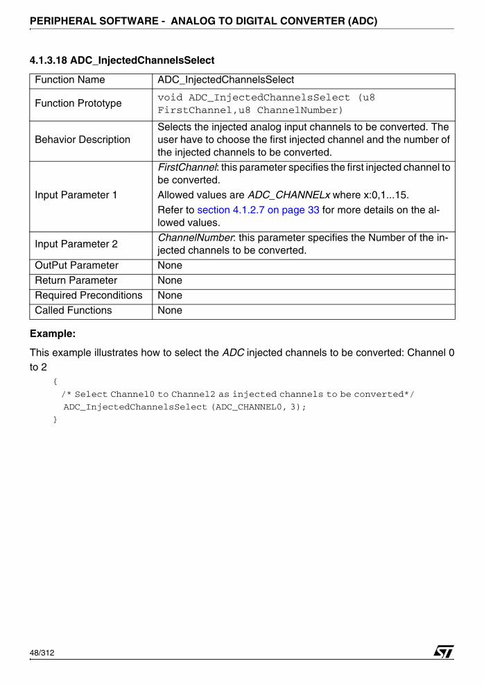
PERIPHERAL SOFTWARE - ANALOG TO DIGITAL CONVERTER (ADC)
4.1.3.18 ADC_InjectedChannelsSelect
Example:
This example illustrates how to select the ADC injected channels to be converted: Channel 0to 2
{
/* Select Channel0 to Channel2 as injected channels to be converted*/
ADC_InjectedChannelsSelect (ADC_CHANNEL0, 3);
}
Function Name ADC_InjectedChannelsSelect
Function Prototypevoid ADC_InjectedChannelsSelect (u8 FirstChannel,u8 ChannelNumber)
Behavior DescriptionSelects the injected analog input channels to be converted. The user have to choose the first injected channel and the number of the injected channels to be converted.
Input Parameter 1
FirstChannel: this parameter specifies the first injected channel to be converted.Allowed values are ADC_CHANNELx where x:0,1...15.
Refer to section 4.1.2.7 on page 33 for more details on the al-lowed values.
Input Parameter 2ChannelNumber: this parameter specifies the Number of the in-jected channels to be converted.
OutPut Parameter None
Return Parameter None
Required Preconditions None
Called Functions None
48/312

PERIPHERAL SOFTWARE - ANALOG TO DIGITAL CONVERTER (ADC)
4.1.3.19 ADC_DMAConfig
Example:
This example illustrates how to configure and enable DMA capability for channel 0 and 1, thendisable it.
{
/* Configure and enable DMA capability channels */
ADC_DMAConfig (ADC_CHANNEL0| ADC_CHANNEL1, ENABLE);
/* Configure and disable DMA capability channels */
ADC_DMAConfig (ADC_CHANNEL0| ADC_CHANNEL1, DISABLE);
}
Function Name ADC_DMAConfig
Function Prototypevoid ADC_DMAConfig(u16 ADC_DMAChannel, FunctionalState NewState)
Behavior Description Selects the channels which their DMA capability will be enabled.
Input Parameter 1
ADC_DMAChannel: this parameter specifies the channels to be enabled.
Allowed values are ADC_DMA_CHANNELx where x:0,1...15.
Refer to Section 4.1.2.7 for more details on the allowed values.
Use the "|" operator to select more than one channel.
Input Parameter 2
NewState: this parameter specifies if the DMA capability of the se-lected ADC channel will be enabled or disabled.
It must be one of the following values: ENABLE: enable DMA capability of the selected ADC channel
DISABLE: disable DMA capability of the selected ADC channel
OutPut Parameter None
Return Parameter None
Required Preconditions None
Called Functions None
49/312

PERIPHERAL SOFTWARE - ANALOG TO DIGITAL CONVERTER (ADC)
4.1.3.20 ADC_DMACmd
Example:
This example illustrates how to enable ADC DMA transfer{
/* Enable ADC DMA transfer*/
ADC_DMACmd (ENABLE);
/* Disable ADC DMA transfer/
ADC_DMACmd (DISABLE);
}
4.1.3.21 ADC_DMAFirstEnabledChannel
Example:
This example illustrates how to get the first enabled channel{
u16 First_Channel; /*First_Channel declaration */
/*Get the first enabled channel*/
First_Channel = ADC_DMAFirstEnabledChannel ();
}
Function Name ADC_DMACmd
Function Prototype void ADC_DMACmd (FunctionalState NewState)
Behavior Description Enable/Disable and set the how the DMA feature will be enabled.
Input Parameter 1 NewState: This parameter enable / disable the DMA feature.
OutPut Parameter None
Return Parameter NoneRequired Preconditions None
Called Functions None
Function Name ADC_DMAFirstEnabledChannel
Function Prototype u16 ADC_DMAFirstEnabledChannel ( void )
Behavior DescriptionReturn the first DMA enabled channel being converted when the DMA was enabled the last time
Input Parameter 1 None
OutPut Parameter NoneReturn Parameter None
Required Preconditions None
Called Functions None
50/312

PERIPHERAL SOFTWARE - BUFFERED SERIAL PERIPHERAL INTERFACE (BSPI)
4.2 BUFFERED SERIAL PERIPHERAL INTERFACE (BSPI)
The BSPI driver may be used to manage the BSPI in transmission and reception and to reportthe status of the action done.
The first section describes the data structures used in the BSPI software library. The secondone presents the software library functions.
4.2.1 Data structures
4.2.1.1 BSPI Register Structure
The BSPI_TypeDef register structure is defined in the 73x_map.h file as follows:typedef struct
{
vuc16 RXR;
u16 EMPTY1;
vu16 TXR;
u16 EMPTY2;
vu16 CSR1;
u16 EMPTY3;
vu16 CSR2;
u16 EMPTY4;
vu16 CLK;
u16 EMPTY5;
vu16 CSR3;
u16 EMPTY6;
} BSPI_TypeDef;
The following table presents the BSPI registers:
The three BSPI interfaces are declared in the same file:...
#define APB_BASE 0xFFFF8000
....
#define BSPI0_BASE (APB + 0x5800)
#define BSPI1_BASE (APB + 0x5C00)
#define BSPI2_BASE (APB + 0x6000)
Register DescriptionRXR BSPI Receive Register
TXR BSPI Transmit Register
CSR1 BSPI Control/Status Register1CSR2 BSPI Control/Status Register2
CLK BSPI Master Clock Divider Register
CSR3 BSPI Control/Status Register3
51/312
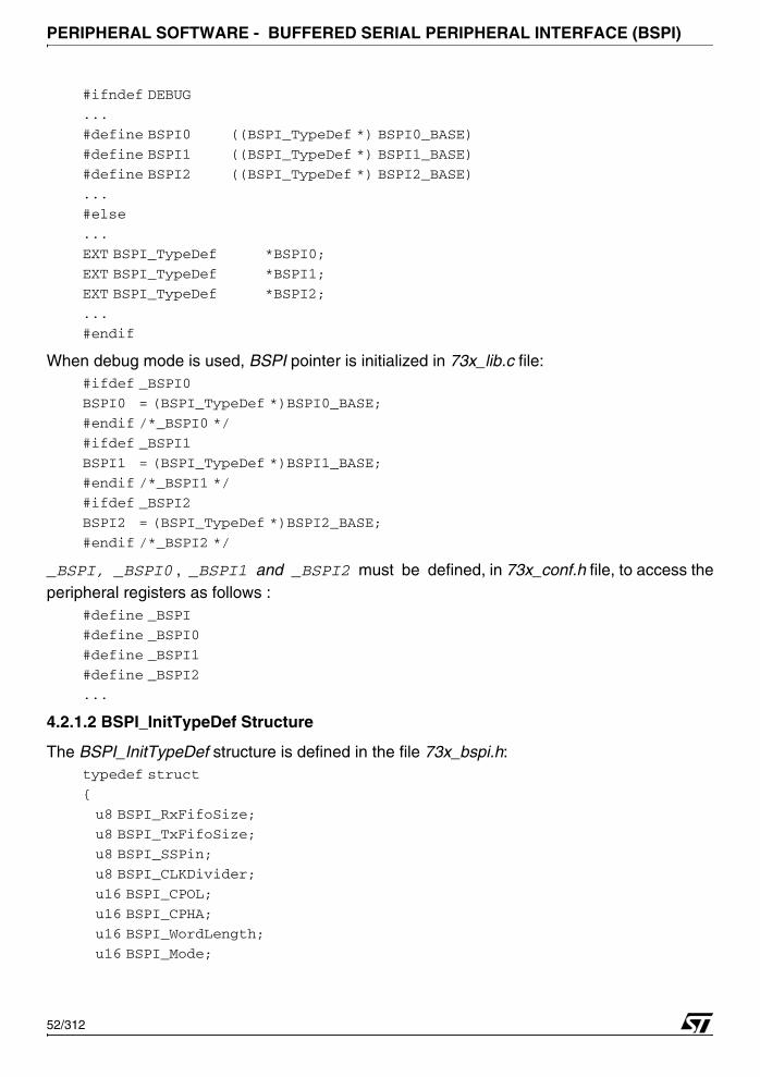
PERIPHERAL SOFTWARE - BUFFERED SERIAL PERIPHERAL INTERFACE (BSPI)
#ifndef DEBUG
...
#define BSPI0 ((BSPI_TypeDef *) BSPI0_BASE)
#define BSPI1 ((BSPI_TypeDef *) BSPI1_BASE)
#define BSPI2 ((BSPI_TypeDef *) BSPI2_BASE)
...
#else
...
EXT BSPI_TypeDef *BSPI0;
EXT BSPI_TypeDef *BSPI1;
EXT BSPI_TypeDef *BSPI2;
...
#endif
When debug mode is used, BSPI pointer is initialized in 73x_lib.c file:#ifdef _BSPI0
BSPI0 = (BSPI_TypeDef *)BSPI0_BASE;
#endif /*_BSPI0 */
#ifdef _BSPI1
BSPI1 = (BSPI_TypeDef *)BSPI1_BASE;
#endif /*_BSPI1 */
#ifdef _BSPI2
BSPI2 = (BSPI_TypeDef *)BSPI2_BASE;
#endif /*_BSPI2 */
_BSPI, _BSPI0 , _BSPI1 and _BSPI2 must be defined, in 73x_conf.h file, to access theperipheral registers as follows :
#define _BSPI
#define _BSPI0
#define _BSPI1
#define _BSPI2
...
4.2.1.2 BSPI_InitTypeDef Structure
The BSPI_InitTypeDef structure is defined in the file 73x_bspi.h:typedef struct
{
u8 BSPI_RxFifoSize;
u8 BSPI_TxFifoSize;
u8 BSPI_SSPin;
u8 BSPI_CLKDivider;
u16 BSPI_CPOL;
u16 BSPI_CPHA;
u16 BSPI_WordLength;
u16 BSPI_Mode;
52/312
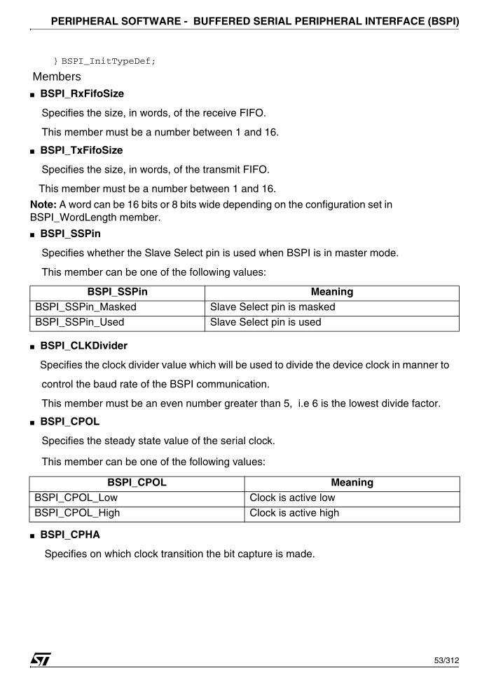
PERIPHERAL SOFTWARE - BUFFERED SERIAL PERIPHERAL INTERFACE (BSPI)
} BSPI_InitTypeDef;
Members■ BSPI_RxFifoSize
Specifies the size, in words, of the receive FIFO.
This member must be a number between 1 and 16.
■ BSPI_TxFifoSize
Specifies the size, in words, of the transmit FIFO.
This member must be a number between 1 and 16.
Note: A word can be 16 bits or 8 bits wide depending on the configuration set in BSPI_WordLength member.
■ BSPI_SSPin
Specifies whether the Slave Select pin is used when BSPI is in master mode.
This member can be one of the following values:
■ BSPI_CLKDivider
Specifies the clock divider value which will be used to divide the device clock in manner to
control the baud rate of the BSPI communication.
This member must be an even number greater than 5, i.e 6 is the lowest divide factor.
■ BSPI_CPOL
Specifies the steady state value of the serial clock.
This member can be one of the following values:
■ BSPI_CPHA
Specifies on which clock transition the bit capture is made.
BSPI_SSPin MeaningBSPI_SSPin_Masked Slave Select pin is masked
BSPI_SSPin_Used Slave Select pin is used
BSPI_CPOL MeaningBSPI_CPOL_Low Clock is active low
BSPI_CPOL_High Clock is active high
53/312

PERIPHERAL SOFTWARE - BUFFERED SERIAL PERIPHERAL INTERFACE (BSPI)
This member can be one of the following values:
■ BSPI_WordLength
Specifies the word length operation of the receive and transit FIFO.
This member can be one of the following values:
■ BSPI_Mode
Specifies the BSPI operation mode. This member can be one of the following values:
4.2.2 Common Parameter Values
4.2.2.1 BSPI interrupts
The BSPI interrupts, defined in 73x_bspi.h, are listed below:
4.2.2.2 BSPI transmit interrupt
The BSPI transmit interrupt, defined in 73x_bspi.h, are listed below:
BSPI_CPHA MeaningBSPI_CPHA_2Edge Data is captured on the second edge
BSPI_CPHA_1Edge Data is captured on the first edge
BSPI_WordLength MeaningBSPI_WordLength_16b Word length is 16 bits
BSPI_WordLength_8b Word length is 8 bits
BSPI_Mode MeaningBSPI_Mode_Master BSPI is configured as a master
BSPI_Mode_Slave BSPI is configured as a slave
BSPI_IT MeaningBSPI_IT_REI Receive error interrupt mask
BSPI_IT_BEI Bus error interrupt mask
BSPI_TxIT MeaningBSPI_TxIT_NONE No interrupt
BSPI_TxIT_TFE Transmit FIFO empty interrupt mask
BSPI_TxIT_TUFL Transmit underflow interrupt maskBSPI_TxIT_TFF Transmit FIFO full interrupt mask
54/312
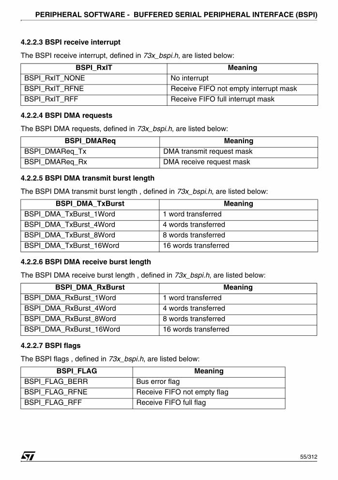
PERIPHERAL SOFTWARE - BUFFERED SERIAL PERIPHERAL INTERFACE (BSPI)
4.2.2.3 BSPI receive interrupt
The BSPI receive interrupt, defined in 73x_bspi.h, are listed below:
4.2.2.4 BSPI DMA requests
The BSPI DMA requests, defined in 73x_bspi.h, are listed below:
4.2.2.5 BSPI DMA transmit burst length
The BSPI DMA transmit burst length , defined in 73x_bspi.h, are listed below:
4.2.2.6 BSPI DMA receive burst length
The BSPI DMA receive burst length , defined in 73x_bspi.h, are listed below:
4.2.2.7 BSPI flags
The BSPI flags , defined in 73x_bspi.h, are listed below:
BSPI_RxIT MeaningBSPI_RxIT_NONE No interrupt
BSPI_RxIT_RFNE Receive FIFO not empty interrupt mask
BSPI_RxIT_RFF Receive FIFO full interrupt mask
BSPI_DMAReq MeaningBSPI_DMAReq_Tx DMA transmit request mask
BSPI_DMAReq_Rx DMA receive request mask
BSPI_DMA_TxBurst MeaningBSPI_DMA_TxBurst_1Word 1 word transferred
BSPI_DMA_TxBurst_4Word 4 words transferred BSPI_DMA_TxBurst_8Word 8 words transferred
BSPI_DMA_TxBurst_16Word 16 words transferred
BSPI_DMA_RxBurst MeaningBSPI_DMA_RxBurst_1Word 1 word transferred
BSPI_DMA_RxBurst_4Word 4 words transferred
BSPI_DMA_RxBurst_8Word 8 words transferred
BSPI_DMA_RxBurst_16Word 16 words transferred
BSPI_FLAG MeaningBSPI_FLAG_BERR Bus error flag
BSPI_FLAG_RFNE Receive FIFO not empty flagBSPI_FLAG_RFF Receive FIFO full flag
55/312
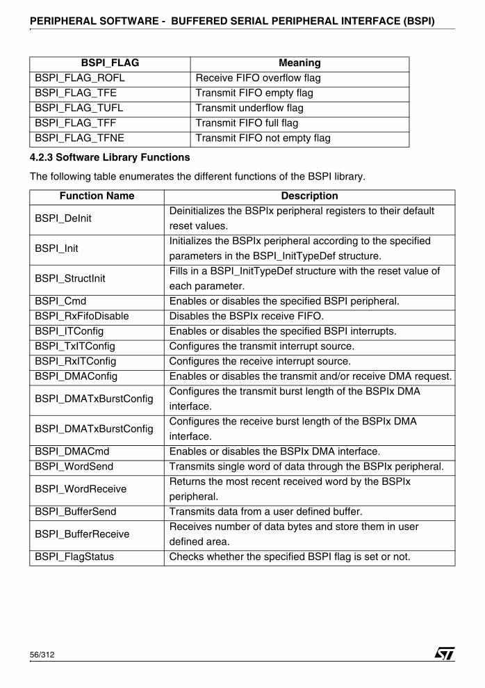
PERIPHERAL SOFTWARE - BUFFERED SERIAL PERIPHERAL INTERFACE (BSPI)
4.2.3 Software Library Functions
The following table enumerates the different functions of the BSPI library.
BSPI_FLAG_ROFL Receive FIFO overflow flagBSPI_FLAG_TFE Transmit FIFO empty flag
BSPI_FLAG_TUFL Transmit underflow flag
BSPI_FLAG_TFF Transmit FIFO full flag
BSPI_FLAG_TFNE Transmit FIFO not empty flag
Function Name Description
BSPI_DeInitDeinitializes the BSPIx peripheral registers to their default
reset values.
BSPI_InitInitializes the BSPIx peripheral according to the specified
parameters in the BSPI_InitTypeDef structure.
BSPI_StructInitFills in a BSPI_InitTypeDef structure with the reset value of
each parameter.
BSPI_Cmd Enables or disables the specified BSPI peripheral.BSPI_RxFifoDisable Disables the BSPIx receive FIFO.
BSPI_ITConfig Enables or disables the specified BSPI interrupts.
BSPI_TxITConfig Configures the transmit interrupt source.
BSPI_RxITConfig Configures the receive interrupt source.
BSPI_DMAConfig Enables or disables the transmit and/or receive DMA request.
BSPI_DMATxBurstConfigConfigures the transmit burst length of the BSPIx DMAinterface.
BSPI_DMATxBurstConfigConfigures the receive burst length of the BSPIx DMA
interface.
BSPI_DMACmd Enables or disables the BSPIx DMA interface.
BSPI_WordSend Transmits single word of data through the BSPIx peripheral.
BSPI_WordReceiveReturns the most recent received word by the BSPIx peripheral.
BSPI_BufferSend Transmits data from a user defined buffer.
BSPI_BufferReceiveReceives number of data bytes and store them in user
defined area.
BSPI_FlagStatus Checks whether the specified BSPI flag is set or not.
BSPI_FLAG Meaning
56/312
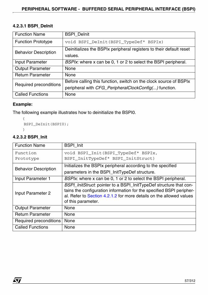
PERIPHERAL SOFTWARE - BUFFERED SERIAL PERIPHERAL INTERFACE (BSPI)
4.2.3.1 BSPI_DeInit
Example:
The following example illustrates how to deinitialize the BSPI0.{
BSPI_DeInit(BSPI0);
}
4.2.3.2 BSPI_Init
Function Name BSPI_DeInit
Function Prototype void BSPI_DeInit(BSPI_TypeDef* BSPIx)
Behavior DescriptionDeinitializes the BSPIx peripheral registers to their default reset
values.
Input Parameter BSPIx: where x can be 0, 1 or 2 to select the BSPI peripheral.
Output Parameter NoneReturn Parameter None
Required preconditionsBefore calling this function, switch on the clock source of BSPIx
peripheral with CFG_PeripheralClockConfig(...) function.
Called Functions None
Function Name BSPI_Init
Function Prototype
void BSPI_Init(BSPI_TypeDef* BSPIx, BSPI_InitTypeDef* BSPI_InitStruct)
Behavior DescriptionInitializes the BSPIx peripheral according to the specified
parameters in the BSPI_InitTypeDef structure.
Input Parameter 1 BSPIx: where x can be 0, 1 or 2 to select the BSPI peripheral.
Input Parameter 2
BSPI_InitStruct: pointer to a BSPI_InitTypeDef structure that con-tains the configuration information for the specified BSPI peripher-al. Refer to Section 4.2.1.2 for more details on the allowed values of this parameter.
Output Parameter None
Return Parameter None
Required preconditions NoneCalled Functions None
57/312

PERIPHERAL SOFTWARE - BUFFERED SERIAL PERIPHERAL INTERFACE (BSPI)
Example:
The following example illustrates how to configure the BSPI0.{
BSPI_InitTypeDef BSPI_InitStructure;
BSPI_InitStructure.BSPI_RxFifoSize = 16;
BSPI_InitStructure.BSPI_TxFifoSize = 16;
BSPI_InitStructure.BSPI_SSPin = BSPI_SSPin_Masked;
BSPI_InitStructure.BSPI_CLKDivider = 6;
BSPI_InitStructure.BSPI_CPOL = BSPI_CPOL_High;
BSPI_InitStructure.BSPI_CPHA = BSPI_CPHA_1Edge;
BSPI_InitStructure.BSPI_WordLength = BSPI_WordLength_8b;
BSPI_InitStructure.BSPI_Mode = BSPI_Mode_Master;
BSPI_Init(BSPI0, &BSPI_InitStructure);
}
4.2.3.3 BSPI_StructInit
Example:
The following example illustrates how to initialize a BSPI_InitTypeDef structure.{
BSPI_InitTypeDef BSPI_InitStructure;
BSPI_StructInit(&BSPI_InitStructure);
}
Function Name BSPI_StructInit
Function Prototypevoid BSPI_StructInit(BSPI_InitTypeDef*
BSPI_InitStruct)
Behavior DescriptionFills in a BSPI_InitTypeDef structure with the reset value of each
parameter.
Input Parameter1 BSPI_InitStruct: pointer to a BSPI_InitTypeDef structure which
will be initialized.
Output Parameter NoneReturn Parameter None
Required preconditions None
Called Functions None
58/312
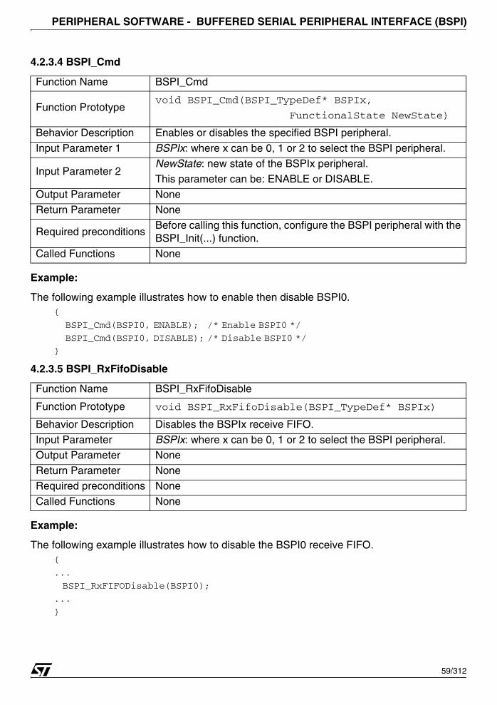
PERIPHERAL SOFTWARE - BUFFERED SERIAL PERIPHERAL INTERFACE (BSPI)
4.2.3.4 BSPI_Cmd
Example:
The following example illustrates how to enable then disable BSPI0.{
BSPI_Cmd(BSPI0, ENABLE); /* Enable BSPI0 */
BSPI_Cmd(BSPI0, DISABLE); /* Disable BSPI0 */
}
4.2.3.5 BSPI_RxFifoDisable
Example:
The following example illustrates how to disable the BSPI0 receive FIFO.{
...
BSPI_RxFIFODisable(BSPI0);
...
}
Function Name BSPI_Cmd
Function Prototypevoid BSPI_Cmd(BSPI_TypeDef* BSPIx,
FunctionalState NewState)
Behavior Description Enables or disables the specified BSPI peripheral.
Input Parameter 1 BSPIx: where x can be 0, 1 or 2 to select the BSPI peripheral.
Input Parameter 2NewState: new state of the BSPIx peripheral. This parameter can be: ENABLE or DISABLE.
Output Parameter None
Return Parameter None
Required preconditionsBefore calling this function, configure the BSPI peripheral with the BSPI_Init(...) function.
Called Functions None
Function Name BSPI_RxFifoDisable
Function Prototype void BSPI_RxFifoDisable(BSPI_TypeDef* BSPIx)
Behavior Description Disables the BSPIx receive FIFO.
Input Parameter BSPIx: where x can be 0, 1 or 2 to select the BSPI peripheral.
Output Parameter None
Return Parameter NoneRequired preconditions None
Called Functions None
59/312
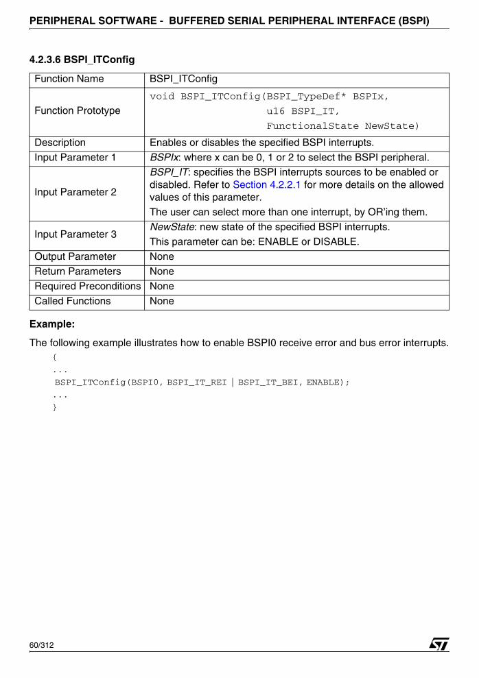
PERIPHERAL SOFTWARE - BUFFERED SERIAL PERIPHERAL INTERFACE (BSPI)
4.2.3.6 BSPI_ITConfig
Example:
The following example illustrates how to enable BSPI0 receive error and bus error interrupts.{
...
BSPI_ITConfig(BSPI0, BSPI_IT_REI | BSPI_IT_BEI, ENABLE);
...
}
Function Name BSPI_ITConfig
Function Prototype
void BSPI_ITConfig(BSPI_TypeDef* BSPIx,
u16 BSPI_IT,
FunctionalState NewState)
Description Enables or disables the specified BSPI interrupts.
Input Parameter 1 BSPIx: where x can be 0, 1 or 2 to select the BSPI peripheral.
Input Parameter 2
BSPI_IT: specifies the BSPI interrupts sources to be enabled or disabled. Refer to Section 4.2.2.1 for more details on the allowed values of this parameter.
The user can select more than one interrupt, by OR’ing them.
Input Parameter 3NewState: new state of the specified BSPI interrupts.
This parameter can be: ENABLE or DISABLE.
Output Parameter None
Return Parameters None
Required Preconditions None
Called Functions None
60/312
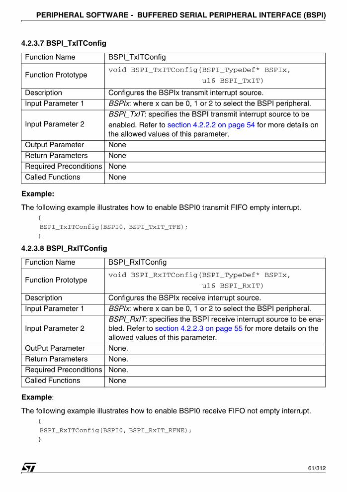
PERIPHERAL SOFTWARE - BUFFERED SERIAL PERIPHERAL INTERFACE (BSPI)
4.2.3.7 BSPI_TxITConfig
Example:
The following example illustrates how to enable BSPI0 transmit FIFO empty interrupt.{
BSPI_TxITConfig(BSPI0, BSPI_TxIT_TFE);
}
4.2.3.8 BSPI_RxITConfig
Example:
The following example illustrates how to enable BSPI0 receive FIFO not empty interrupt.{
BSPI_RxITConfig(BSPI0, BSPI_RxIT_RFNE);
}
Function Name BSPI_TxITConfig
Function Prototypevoid BSPI_TxITConfig(BSPI_TypeDef* BSPIx,
u16 BSPI_TxIT)
Description Configures the BSPIx transmit interrupt source.
Input Parameter 1 BSPIx: where x can be 0, 1 or 2 to select the BSPI peripheral.
Input Parameter 2BSPI_TxIT: specifies the BSPI transmit interrupt source to be enabled. Refer to section 4.2.2.2 on page 54 for more details on the allowed values of this parameter.
Output Parameter None
Return Parameters None
Required Preconditions None
Called Functions None
Function Name BSPI_RxITConfig
Function Prototypevoid BSPI_RxITConfig(BSPI_TypeDef* BSPIx,
u16 BSPI_RxIT)
Description Configures the BSPIx receive interrupt source.
Input Parameter 1 BSPIx: where x can be 0, 1 or 2 to select the BSPI peripheral.
Input Parameter 2BSPI_RxIT: specifies the BSPI receive interrupt source to be ena-bled. Refer to section 4.2.2.3 on page 55 for more details on the allowed values of this parameter.
OutPut Parameter None.Return Parameters None.
Required Preconditions None.
Called Functions None
61/312
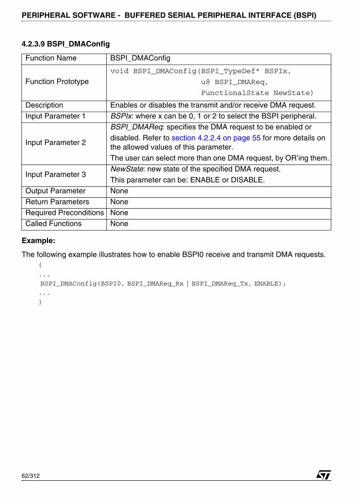
PERIPHERAL SOFTWARE - BUFFERED SERIAL PERIPHERAL INTERFACE (BSPI)
4.2.3.9 BSPI_DMAConfig
Example:
The following example illustrates how to enable BSPI0 receive and transmit DMA requests.{
...
BSPI_DMAConfig(BSPI0, BSPI_DMAReq_Rx | BSPI_DMAReq_Tx, ENABLE);
...
}
Function Name BSPI_DMAConfig
Function Prototype
void BSPI_DMAConfig(BSPI_TypeDef* BSPIx,
u8 BSPI_DMAReq,
FunctionalState NewState)
Description Enables or disables the transmit and/or receive DMA request.
Input Parameter 1 BSPIx: where x can be 0, 1 or 2 to select the BSPI peripheral.
Input Parameter 2
BSPI_DMAReq: specifies the DMA request to be enabled or
disabled. Refer to section 4.2.2.4 on page 55 for more details on the allowed values of this parameter.
The user can select more than one DMA request, by OR’ing them.
Input Parameter 3NewState: new state of the specified DMA request.
This parameter can be: ENABLE or DISABLE.
Output Parameter None
Return Parameters NoneRequired Preconditions None
Called Functions None
62/312
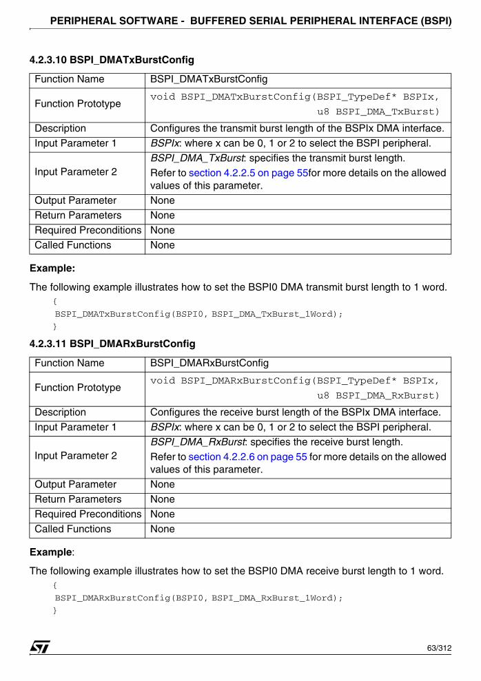
PERIPHERAL SOFTWARE - BUFFERED SERIAL PERIPHERAL INTERFACE (BSPI)
4.2.3.10 BSPI_DMATxBurstConfig
Example:
The following example illustrates how to set the BSPI0 DMA transmit burst length to 1 word.{
BSPI_DMATxBurstConfig(BSPI0, BSPI_DMA_TxBurst_1Word);
}
4.2.3.11 BSPI_DMARxBurstConfig
Example:
The following example illustrates how to set the BSPI0 DMA receive burst length to 1 word.{
BSPI_DMARxBurstConfig(BSPI0, BSPI_DMA_RxBurst_1Word);
}
Function Name BSPI_DMATxBurstConfig
Function Prototypevoid BSPI_DMATxBurstConfig(BSPI_TypeDef* BSPIx,
u8 BSPI_DMA_TxBurst)
Description Configures the transmit burst length of the BSPIx DMA interface.
Input Parameter 1 BSPIx: where x can be 0, 1 or 2 to select the BSPI peripheral.
Input Parameter 2BSPI_DMA_TxBurst: specifies the transmit burst length. Refer to section 4.2.2.5 on page 55for more details on the allowed values of this parameter.
Output Parameter None
Return Parameters None
Required Preconditions None
Called Functions None
Function Name BSPI_DMARxBurstConfig
Function Prototypevoid BSPI_DMARxBurstConfig(BSPI_TypeDef* BSPIx,
u8 BSPI_DMA_RxBurst)
Description Configures the receive burst length of the BSPIx DMA interface.
Input Parameter 1 BSPIx: where x can be 0, 1 or 2 to select the BSPI peripheral.
Input Parameter 2BSPI_DMA_RxBurst: specifies the receive burst length.
Refer to section 4.2.2.6 on page 55 for more details on the allowed values of this parameter.
Output Parameter None
Return Parameters None
Required Preconditions None
Called Functions None
63/312
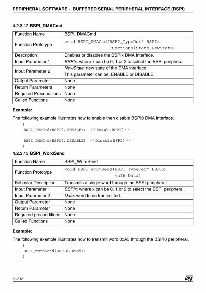
PERIPHERAL SOFTWARE - BUFFERED SERIAL PERIPHERAL INTERFACE (BSPI)
4.2.3.12 BSPI_DMACmd
Example:
The following example illustrates how to enable then disable BSPI0 DMA interface.{
BSPI_DMACmd(BSPI0, ENABLE); /* Enable BSPI0 */
...
BSPI_DMACmd(BSPI0, DISABLE); /* Disable BSPI0 */
}
4.2.3.13 BSPI_WordSend
Example:
The following example illustrates how to transmit word 0xA5 through the BSPI0 peripheral.{
BSPI_WordSend(BSPI0, 0xA5);
}
Function Name BSPI_DMACmd
Function Prototypevoid BSPI_DMACmd(BSPI_TypeDef* BSPIx,
FunctionalState NewState)
Description Enables or disables the BSPIx DMA interface.
Input Parameter 1 BSPIx: where x can be 0, 1 or 2 to select the BSPI peripheral.
Input Parameter 2NewState: new state of the DMA interface. This parameter can be: ENABLE or DISABLE.
Output Parameter None
Return Parameters None
Required Preconditions None
Called Functions None
Function Name BSPI_WordSend
Function Prototypevoid BSPI_WordSend(BSPI_TypeDef* BSPIx,
vu16 Data)
Behavior Description Transmits a single word through the BSPI peripheral.
Input Parameter 1 BSPIx: where x can be 0, 1 or 2 to select the BSPI peripheral.
Input Parameter 2 Data: word to be transmitted.Output Parameter None
Return Parameter None
Required preconditions None
Called Functions None
64/312

PERIPHERAL SOFTWARE - BUFFERED SERIAL PERIPHERAL INTERFACE (BSPI)
4.2.3.14 BSPI_BufferSend
Example:
The following example illustrates how to transmit word 0xA5 through the BSPI0 peripheral.{
u8 Tx_Buffer[] = “Hello World”;
ErrorStatus Status;
Status = BSPI_BufferSend(BSPI0, Tx_Buffer, strlen(Tx_Buffer));
}
Function Name BSPI_BufferSend
Function Prototype
ErrorStatus BSPI_BufferSend(BSPI_TypeDef *BSPIx,
vu8* PtrToBuffer,
vu8 NbOfBytes)
Behavior DescriptionTransmits data from a user defined buffer. This function will fail if
an error occurs.Input Parameter 1 BSPIx: where x can be 0, 1 or 2 to select the BSPI peripheral.
Input Parameter 2PtrToBuffer: ‘u8’ pointer to the buffer that contains the data to be
transmitted.
Input Parameter 3NbOfBytes: specifies the number of bytes to be transferred from
the buffer.
Output Parameter None
Return Parameter
An ErrorStatus enumeration value:
SUCCESS: transmission done without error
ERROR: an error detected during transmission
Required preconditionsThis function can be used only if the BSPI word length is set to
8-bit data.
Called Functions BSPI_FlagStatus()
65/312
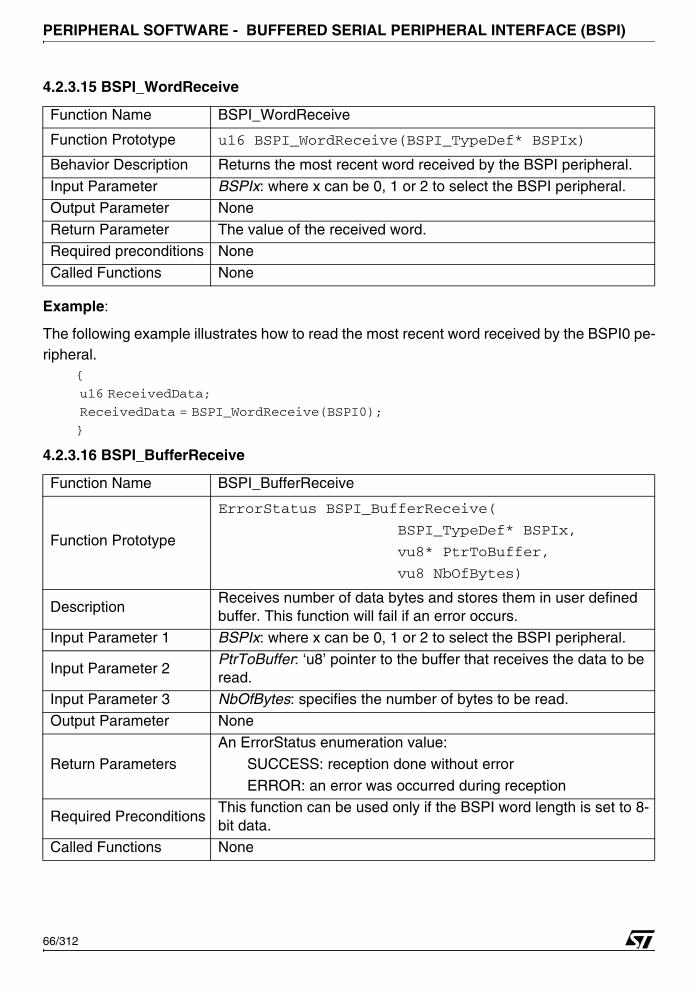
PERIPHERAL SOFTWARE - BUFFERED SERIAL PERIPHERAL INTERFACE (BSPI)
4.2.3.15 BSPI_WordReceive
Example:
The following example illustrates how to read the most recent word received by the BSPI0 pe-ripheral.
{
u16 ReceivedData;
ReceivedData = BSPI_WordReceive(BSPI0);
}
4.2.3.16 BSPI_BufferReceive
Function Name BSPI_WordReceive
Function Prototype u16 BSPI_WordReceive(BSPI_TypeDef* BSPIx)
Behavior Description Returns the most recent word received by the BSPI peripheral.
Input Parameter BSPIx: where x can be 0, 1 or 2 to select the BSPI peripheral.
Output Parameter None
Return Parameter The value of the received word.Required preconditions None
Called Functions None
Function Name BSPI_BufferReceive
Function Prototype
ErrorStatus BSPI_BufferReceive(
BSPI_TypeDef* BSPIx,
vu8* PtrToBuffer,
vu8 NbOfBytes)
DescriptionReceives number of data bytes and stores them in user defined buffer. This function will fail if an error occurs.
Input Parameter 1 BSPIx: where x can be 0, 1 or 2 to select the BSPI peripheral.
Input Parameter 2PtrToBuffer: ‘u8’ pointer to the buffer that receives the data to be read.
Input Parameter 3 NbOfBytes: specifies the number of bytes to be read.
Output Parameter None
Return Parameters
An ErrorStatus enumeration value:
SUCCESS: reception done without error
ERROR: an error was occurred during reception
Required PreconditionsThis function can be used only if the BSPI word length is set to 8-bit data.
Called Functions None
66/312
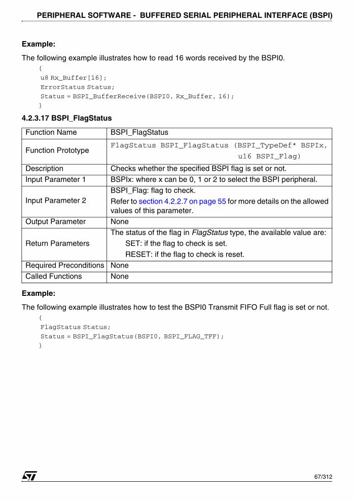
PERIPHERAL SOFTWARE - BUFFERED SERIAL PERIPHERAL INTERFACE (BSPI)
Example:
The following example illustrates how to read 16 words received by the BSPI0.{
u8 Rx_Buffer[16];
ErrorStatus Status;
Status = BSPI_BufferReceive(BSPI0, Rx_Buffer, 16);
}
4.2.3.17 BSPI_FlagStatus
Example:
The following example illustrates how to test the BSPI0 Transmit FIFO Full flag is set or not.{
FlagStatus Status;
Status = BSPI_FlagStatus(BSPI0, BSPI_FLAG_TFF);
}
Function Name BSPI_FlagStatus
Function PrototypeFlagStatus BSPI_FlagStatus (BSPI_TypeDef* BSPIx,
u16 BSPI_Flag)
Description Checks whether the specified BSPI flag is set or not.
Input Parameter 1 BSPIx: where x can be 0, 1 or 2 to select the BSPI peripheral.
Input Parameter 2BSPI_Flag: flag to check.
Refer to section 4.2.2.7 on page 55 for more details on the allowed values of this parameter.
Output Parameter None
Return ParametersThe status of the flag in FlagStatus type, the available value are: SET: if the flag to check is set.
RESET: if the flag to check is reset.
Required Preconditions None
Called Functions None
67/312
PERIPHERAL SOFTWARE - CONTROLLER AREA NETWORK (CAN)
4.3 CONTROLLER AREA NETWORK (CAN)
The CAN driver may be used to manage the 3 CAN cells.
The first section describes the data structures used in the CAN software library. The secondone presents the software library functions.
4.3.1 Data structures
4.3.1.1 CAN Registers structure
The CAN peripheral register structure CAN_TypeDef and CAN_MsgObj_TypeDef is definedin the 73x_map.h file as follows
typedef struct
{
vu16 CRR;
u16 EMPTY1;
vu16 CMR;
u16 EMPTY2;
vu16 M1R;
u16 EMPTY3;
vu16 M2R;
u16 EMPTY4;
vu16 A1R;
u16 EMPTY5;
vu16 A2R;
u16 EMPTY6;
vu16 MCR;
u16 EMPTY7;
vu16 DA1R;
u16 EMPTY8;
vu16 DA2R;
u16 EMPTY9;
vu16 DB1R;
u16 EMPTY10;
vu16 DB2R;
u16 EMPTY11[27];
} CAN_MsgObj_TypeDef;
68/312

PERIPHERAL SOFTWARE - CONTROLLER AREA NETWORK (CAN)
typedef struct
{
vu16 CR;
u16 EMPTY1;
vu16 SR;
u16 EMPTY2;
vu16 ERR;
u16 EMPTY3;
vu16 BTR;
u16 EMPTY4;
vu16 IDR;
u16 EMPTY5;
vu16 TESTR;
u16 EMPTY6;
vu16 BRPR;
u16 EMPTY7[3];
CAN_MsgObj_TypeDef sMsgObj[2];
u16 EMPTY8[16];
vu16 TXR1R;
u16 EMPTY9;
vu16 TXR2R;
u16 EMPTY10[13];
vu16 ND1R;
u16 EMPTY11;
vu16 ND2R;
u16 EMPTY12[13];
vu16 IP1R;
u16 EMPTY13;
vu16 IP2R;
u16 EMPTY14[13];
vu16 MV1R;
u16 EMPTY15;
vu16 MV2R;
u16 EMPTY16;
} CAN_TypeDef;
The following table summarises the CAN registers:
Register DescriptionCR CAN Control Register
SR CAN Status Register
ERR; CAN Error counter Register
BTR CAN Bit Timing Register
IDR CAN Interrupt Identifier Register
69/312

PERIPHERAL SOFTWARE - CONTROLLER AREA NETWORK (CAN)
The CAN peripherals are declared in the same file:...
#define APB 0xFFFF8000
...
#define CAN0_BASE (APB + 0x4400)
TESTR CAN Test RegisterBRPR CAN BRP Extension Register
CRR CAN IF1 Command request Register
CMR CAN IF1 Command Mask Register
M1R CAN IF1 Message Mask 1 Register
M2R CAN IF1 Message Mask 2 Register
A1R CAN IF1 Message Arbitration 1 RegisterA2R CAN IF1 Message Arbitration 2 Register
MCR CAN IF1 Message Control Register
DA1R CAN IF1 DATA A 1 Register
DA2R CAN IF1 DATA A 2 Register
DB1R CAN IF1 DATA B 1 Register
DB2R CAN IF1 DATA B 2 RegisterCRR CAN IF2 Command request Register
CMR CAN IF2 Command Mask Register
M1R CAN IF2 Message Mask 1 Register
M2R CAN IF2 Message Mask 2 Register
A1R CAN IF2 Message Arbitration 1 Register
A2R CAN IF2 Message Arbitration 2 Register
MCR CAN IF2 Message Control RegisterDA1R CAN IF2 DATA A 1 Register
DA2R CAN IF2 DATA A 2 Register
DB1R CAN IF2 DATA B 1 Register
DB2R CAN IF2 DATA B 2 Register
TXR1R CAN Transmission request 1 Register
TXR2R CAN Transmission Request 2 RegisterND1R CAN New Data 1 Register
ND2R CAN New Data 2 Register
IP1R CAN Interrupt Pending 1 Register
IP2R CAN Interrupt Pending 2 Register
MV1R CAN Message Valid 1 Register
MV2R CAN Message VAlid 2 Register
Register Description
70/312
PERIPHERAL SOFTWARE - CONTROLLER AREA NETWORK (CAN)
#define CAN1_BASE (APB + 0x4800)
#define CAN2_BASE (APB + 0x4C00)
...
#ifndef DEBUG
...
#define CAN0 ((CAN_TypeDef *) CAN0_BASE)
#define CAN1 ((CAN_TypeDef *) CAN1_BASE)
#define CAN2 ((CAN_TypeDef *) CAN2_BASE)
...
#else
...
EXT CAN_TypeDef *CAN0;
EXT CAN_TypeDef *CAN1;
EXT CAN_TypeDef *CAN2;
...
#endif
When debug mode is used, CAN pointers are initialized in 73x_lib.c file:void debug(void)
{
...
#ifdef _CAN0
CAN0 = (CAN_TypeDef *)CAN0_BASE;
#endif /*CAN0 */
#ifdef _CAN1
CAN1 = (CAN_TypeDef *)CAN1_BASE;
#endif /*CAN1 */
#ifdef _CAN1
CAN2 = (CAN_TypeDef *)CAN2_BASE;
#endif /*CAN2 */
...
}
In debug mode, _CAN0, _CAN1 and _CAN2 must be defined, in 73x_conf.h file, to access theperipheral registers as follows:
#define _CAN0
#define _CAN1
#define _CAN2
71/312
PERIPHERAL SOFTWARE - CONTROLLER AREA NETWORK (CAN)
4.3.1.2 CAN_InitTypeDef Structure
The CAN_InitTypeDef structure defines the control setting for the CAN peripheral.typedef struct
{
vu8 CAN_Mask;
vu32 CAN_Bitrate;
}CAN_InitTypeDef;
Members■ CAN_Mask
Any binary value formed from the CAN_CR_xxx defines.
■ CAN_Bitrate
One of the CAN_BITRATE_xxx defines.
4.3.2 Common Parameter Values
4.3.2.1 CAN Control
The CAN Control register bits are defined in the file 73x_can.h:
CAN_Mask MeaningCAN_CR_TEST Test mode enable
CAN_CR_CCE Configuration change enable
CAN_CR_DAR Disable automatic re transmissionCAN_CR_EIE Error interrupt enable
CAN_CR_SIE Status change interrupt enable
CAN_CR_IE Module interrupt enable
CAN_CR_INIT Initialization
CAN_Bitrate MeaningCAN_BITRATE_100K 100kbit/s bit rate
CAN_BITRATE_125K 125kbit/s bit rate
CAN_BITRATE_250K 250kbit/s bit rate
CAN_BITRATE_500K 500kbit/s bit rate
CAN_BITRATE_1M 1Mbit/s bit rate
CAN Control MeaningCAN_CR_TEST Test mode enable
CAN_CR_CCE Configuration change enable
72/312

PERIPHERAL SOFTWARE - CONTROLLER AREA NETWORK (CAN)
4.3.2.2 CAN Status
The CAN status register bits are defined in the file 73x_can.h as follows:
4.3.2.3 CAN Test
The CAN test register bits are defined in the file 73x_can.h:
4.3.2.4 CAN IFn / Command Request
The CAN IFn/ Command request register bit is defined in the file 73x_can.h:
CAN_CR_DAR Disable automatic re transmissionCAN_CR_EIE Error interrupt enable
CAN_CR_SIE Status change interrupt enable
CAN_CR_IE Module interrupt enable
CAN_CR_INIT Initialization
CAN Status MeaningCAN_SR_BOFF Bus off status
CAN_SR_EWARN warning status
CAN_SR_EPASS error passive
CAN_SR_RXOK receive a message successfully
CAN_SR_TXOK Transmitted a message successfully
CAN_SR_LEC Last error code
CAN Test MeaningCAN_TESTR_RX Monitors the actual value of CAN_RX pin
CAN_TESTR_TX1 Control of CAN_TX pin
CAN_TESTR_TX0 Control of CAN_TX pin
CAN_TESTR_LBACK Loop back mode
CAN_TESTR_SILENT Silent modeCAN_TESTR_BASIC Basic mode
CAN Command request MeaningCAN_CRR_BUSY Busy flag
CAN Control Meaning
73/312
PERIPHERAL SOFTWARE - CONTROLLER AREA NETWORK (CAN)
4.3.2.5 CAN IFn / Command Mask
The CAN IFn / command mask bits are defined in the file 73x_can.h:
4.3.2.6 CAN IFn / Mask 2
The CAN IFn / Mask 2 bits are defined in the file 73x_can.h:
4.3.2.7 CAN IFn / Arbitration 2
The CAN IFn / Arbitration 2 bits are defined in the file 73x_can.h:
4.3.2.8 CAN IFn / Message Control
The CAN IFn / Message Control bits are defined in the file 73x_can.h:
CAN IFn / Command Mask MeaningCAN_CMR_WRRD Write / readCAN_CMR_MASK Access mask bits
CAN_CMR_ARB Access arbitration bits
CAN_CMR_CONTROL Access control bits
CAN_CMR_CLRINTPND Clear interrupt pending bit
CAN_CMR_TXRQSTNEWDAT Access transmission request bit
CAN_CMR_DATAA Access data bytes 0-3CAN_CMR_DATAB Access data bytes 4-7
CAN IFn / Mask 2 MeaningCAN_M2R_MXTD Mask extended identifier
CAN_M2R_MDIR Mask message direction
CAN IFn / Arbitration 2 MeaningCAN_A2R_MSGVAL Message valid
CAN_A2R_XTD Extended identifier
CAN_A2R_DIR Message direction
CAN IFn / Message Control Meaning
CAN_MCR_NEWDAT New data
CAN_MCR_MSGLST Message lost
CAN_MCR_INTPND Interrupt pending
CAN_MCR_UMASK Use acceptance mask
74/312
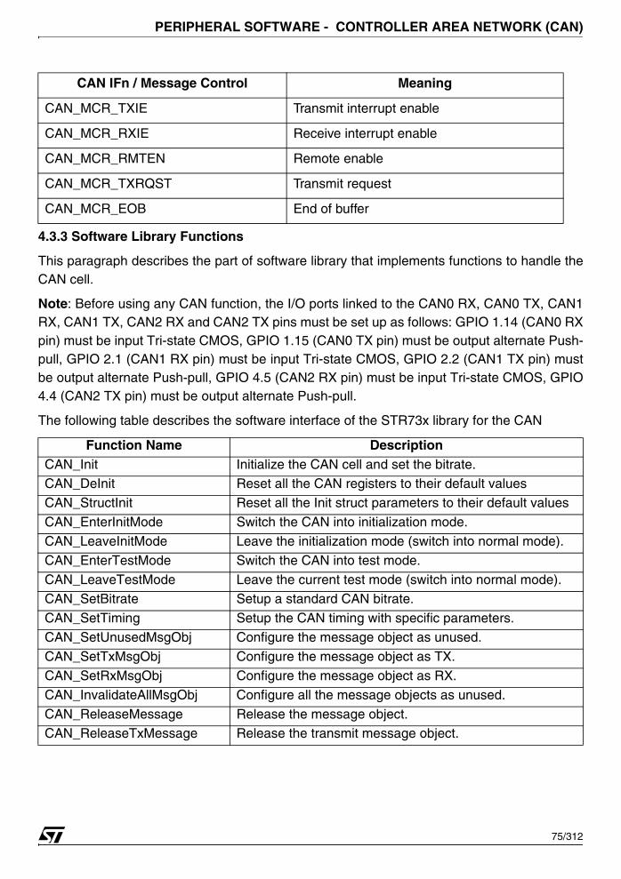
PERIPHERAL SOFTWARE - CONTROLLER AREA NETWORK (CAN)
4.3.3 Software Library Functions
This paragraph describes the part of software library that implements functions to handle theCAN cell.
Note: Before using any CAN function, the I/O ports linked to the CAN0 RX, CAN0 TX, CAN1RX, CAN1 TX, CAN2 RX and CAN2 TX pins must be set up as follows: GPIO 1.14 (CAN0 RXpin) must be input Tri-state CMOS, GPIO 1.15 (CAN0 TX pin) must be output alternate Push-pull, GPIO 2.1 (CAN1 RX pin) must be input Tri-state CMOS, GPIO 2.2 (CAN1 TX pin) mustbe output alternate Push-pull, GPIO 4.5 (CAN2 RX pin) must be input Tri-state CMOS, GPIO4.4 (CAN2 TX pin) must be output alternate Push-pull.
The following table describes the software interface of the STR73x library for the CAN
CAN_MCR_TXIE Transmit interrupt enable
CAN_MCR_RXIE Receive interrupt enable
CAN_MCR_RMTEN Remote enable
CAN_MCR_TXRQST Transmit request
CAN_MCR_EOB End of buffer
Function Name DescriptionCAN_Init Initialize the CAN cell and set the bitrate.CAN_DeInit Reset all the CAN registers to their default values
CAN_StructInit Reset all the Init struct parameters to their default values
CAN_EnterInitMode Switch the CAN into initialization mode.
CAN_LeaveInitMode Leave the initialization mode (switch into normal mode).
CAN_EnterTestMode Switch the CAN into test mode.
CAN_LeaveTestMode Leave the current test mode (switch into normal mode).CAN_SetBitrate Setup a standard CAN bitrate.
CAN_SetTiming Setup the CAN timing with specific parameters.
CAN_SetUnusedMsgObj Configure the message object as unused.
CAN_SetTxMsgObj Configure the message object as TX.
CAN_SetRxMsgObj Configure the message object as RX.
CAN_InvalidateAllMsgObj Configure all the message objects as unused.
CAN_ReleaseMessage Release the message object.CAN_ReleaseTxMessage Release the transmit message object.
CAN IFn / Message Control Meaning
75/312
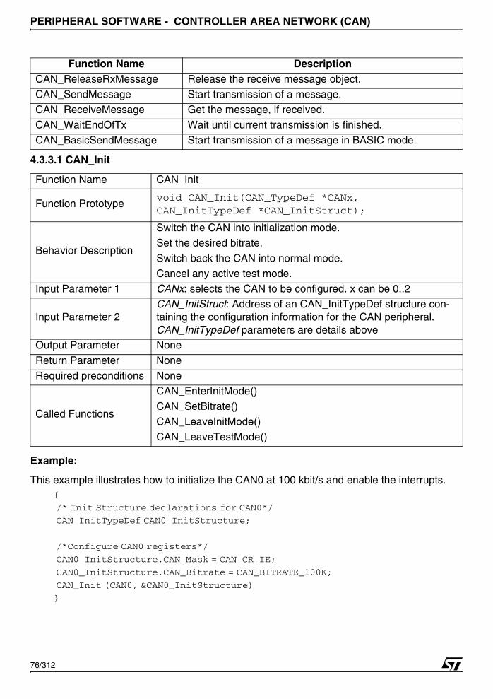
PERIPHERAL SOFTWARE - CONTROLLER AREA NETWORK (CAN)
4.3.3.1 CAN_Init
Example:
This example illustrates how to initialize the CAN0 at 100 kbit/s and enable the interrupts.{
/* Init Structure declarations for CAN0*/
CAN_InitTypeDef CAN0_InitStructure;
/*Configure CAN0 registers*/
CAN0_InitStructure.CAN_Mask = CAN_CR_IE;
CAN0_InitStructure.CAN_Bitrate = CAN_BITRATE_100K;
CAN_Init (CAN0, &CAN0_InitStructure)
}
CAN_ReleaseRxMessage Release the receive message object.CAN_SendMessage Start transmission of a message.
CAN_ReceiveMessage Get the message, if received.
CAN_WaitEndOfTx Wait until current transmission is finished.
CAN_BasicSendMessage Start transmission of a message in BASIC mode.
Function Name CAN_Init
Function Prototypevoid CAN_Init(CAN_TypeDef *CANx, CAN_InitTypeDef *CAN_InitStruct);
Behavior Description
Switch the CAN into initialization mode.
Set the desired bitrate.
Switch back the CAN into normal mode.
Cancel any active test mode.Input Parameter 1 CANx: selects the CAN to be configured. x can be 0..2
Input Parameter 2CAN_InitStruct: Address of an CAN_InitTypeDef structure con-taining the configuration information for the CAN peripheral. CAN_InitTypeDef parameters are details above
Output Parameter None
Return Parameter None
Required preconditions None
Called Functions
CAN_EnterInitMode()
CAN_SetBitrate()
CAN_LeaveInitMode()
CAN_LeaveTestMode()
Function Name Description
76/312
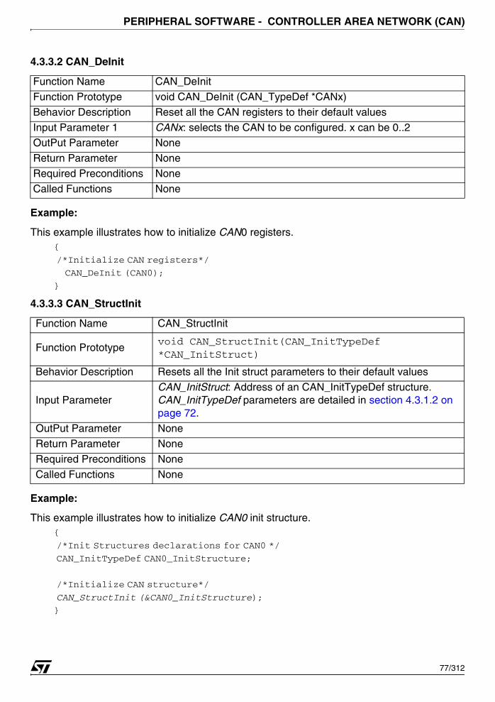
PERIPHERAL SOFTWARE - CONTROLLER AREA NETWORK (CAN)
4.3.3.2 CAN_DeInit
Example:
This example illustrates how to initialize CAN0 registers.{
/*Initialize CAN registers*/
CAN_DeInit (CAN0);
}
4.3.3.3 CAN_StructInit
Example:
This example illustrates how to initialize CAN0 init structure.{
/*Init Structures declarations for CAN0 */
CAN_InitTypeDef CAN0_InitStructure;
/*Initialize CAN structure*/
CAN_StructInit (&CAN0_InitStructure);
}
Function Name CAN_DeInit
Function Prototype void CAN_DeInit (CAN_TypeDef *CANx)
Behavior Description Reset all the CAN registers to their default values
Input Parameter 1 CANx: selects the CAN to be configured. x can be 0..2OutPut Parameter None
Return Parameter None
Required Preconditions None
Called Functions None
Function Name CAN_StructInit
Function Prototypevoid CAN_StructInit(CAN_InitTypeDef *CAN_InitStruct)
Behavior Description Resets all the Init struct parameters to their default values
Input ParameterCAN_InitStruct: Address of an CAN_InitTypeDef structure. CAN_InitTypeDef parameters are detailed in section 4.3.1.2 on page 72.
OutPut Parameter None
Return Parameter None
Required Preconditions None
Called Functions None
77/312
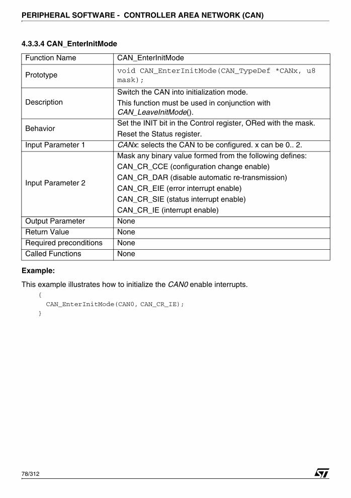
PERIPHERAL SOFTWARE - CONTROLLER AREA NETWORK (CAN)
4.3.3.4 CAN_EnterInitMode
Example:
This example illustrates how to initialize the CAN0 enable interrupts.{
CAN_EnterInitMode(CAN0, CAN_CR_IE);
}
Function Name CAN_EnterInitMode
Prototypevoid CAN_EnterInitMode(CAN_TypeDef *CANx, u8 mask);
DescriptionSwitch the CAN into initialization mode.
This function must be used in conjunction with CAN_LeaveInitMode().
BehaviorSet the INIT bit in the Control register, ORed with the mask.
Reset the Status register.
Input Parameter 1 CANx: selects the CAN to be configured. x can be 0.. 2.
Input Parameter 2
Mask any binary value formed from the following defines:CAN_CR_CCE (configuration change enable)
CAN_CR_DAR (disable automatic re-transmission)
CAN_CR_EIE (error interrupt enable)
CAN_CR_SIE (status interrupt enable)
CAN_CR_IE (interrupt enable)
Output Parameter NoneReturn Value None
Required preconditions None
Called Functions None
78/312
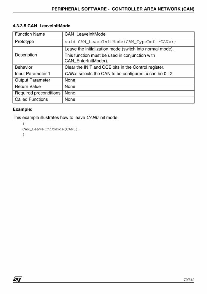
PERIPHERAL SOFTWARE - CONTROLLER AREA NETWORK (CAN)
4.3.3.5 CAN_LeaveInitMode
Example:
This example illustrates how to leave CAN0 init mode.{
CAN_Leave InitMode(CAN0);
}
Function Name CAN_LeaveInitMode
Prototype void CAN_LeaveInitMode(CAN_TypeDef *CANx);
DescriptionLeave the initialization mode (switch into normal mode).
This function must be used in conjunction with CAN_EnterInitMode().
Behavior Clear the INIT and CCE bits in the Control register.
Input Parameter 1 CANx: selects the CAN to be configured. x can be 0.. 2
Output Parameter NoneReturn Value None
Required preconditions None
Called Functions None
79/312
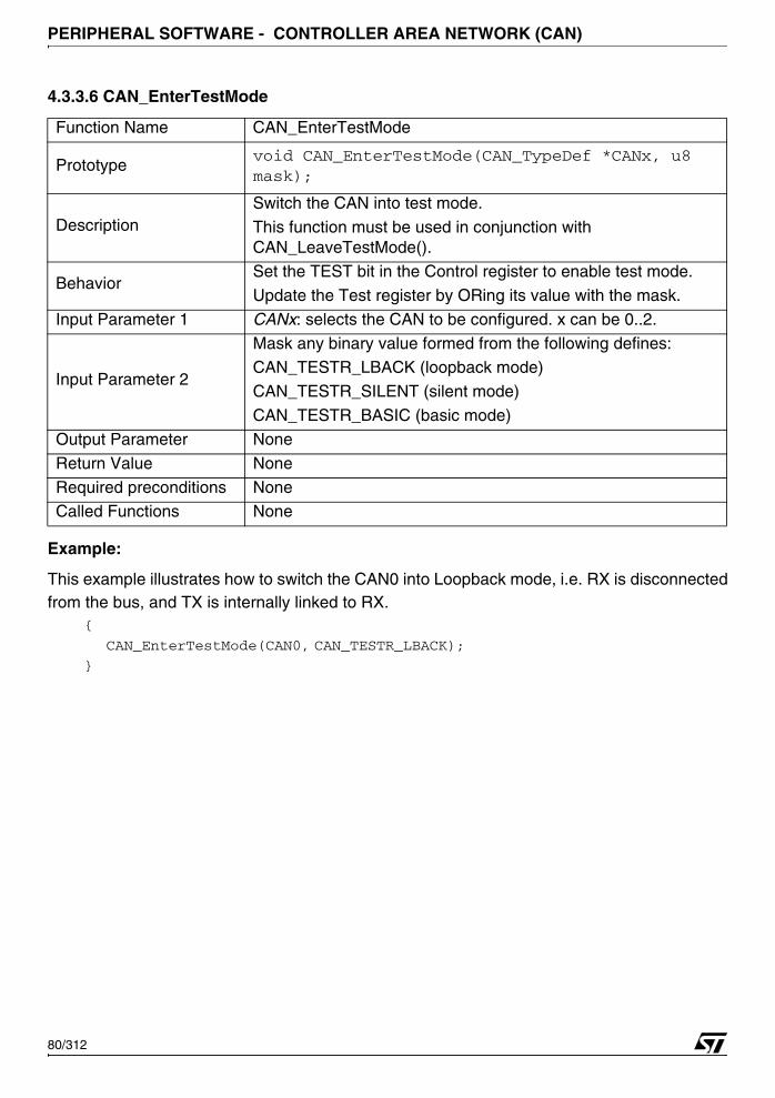
PERIPHERAL SOFTWARE - CONTROLLER AREA NETWORK (CAN)
4.3.3.6 CAN_EnterTestMode
Example:
This example illustrates how to switch the CAN0 into Loopback mode, i.e. RX is disconnectedfrom the bus, and TX is internally linked to RX.
{
CAN_EnterTestMode(CAN0, CAN_TESTR_LBACK);
}
Function Name CAN_EnterTestMode
Prototypevoid CAN_EnterTestMode(CAN_TypeDef *CANx, u8 mask);
DescriptionSwitch the CAN into test mode.
This function must be used in conjunction with CAN_LeaveTestMode().
BehaviorSet the TEST bit in the Control register to enable test mode.
Update the Test register by ORing its value with the mask.
Input Parameter 1 CANx: selects the CAN to be configured. x can be 0..2.
Input Parameter 2
Mask any binary value formed from the following defines:CAN_TESTR_LBACK (loopback mode)
CAN_TESTR_SILENT (silent mode)
CAN_TESTR_BASIC (basic mode)
Output Parameter None
Return Value None
Required preconditions NoneCalled Functions None
80/312
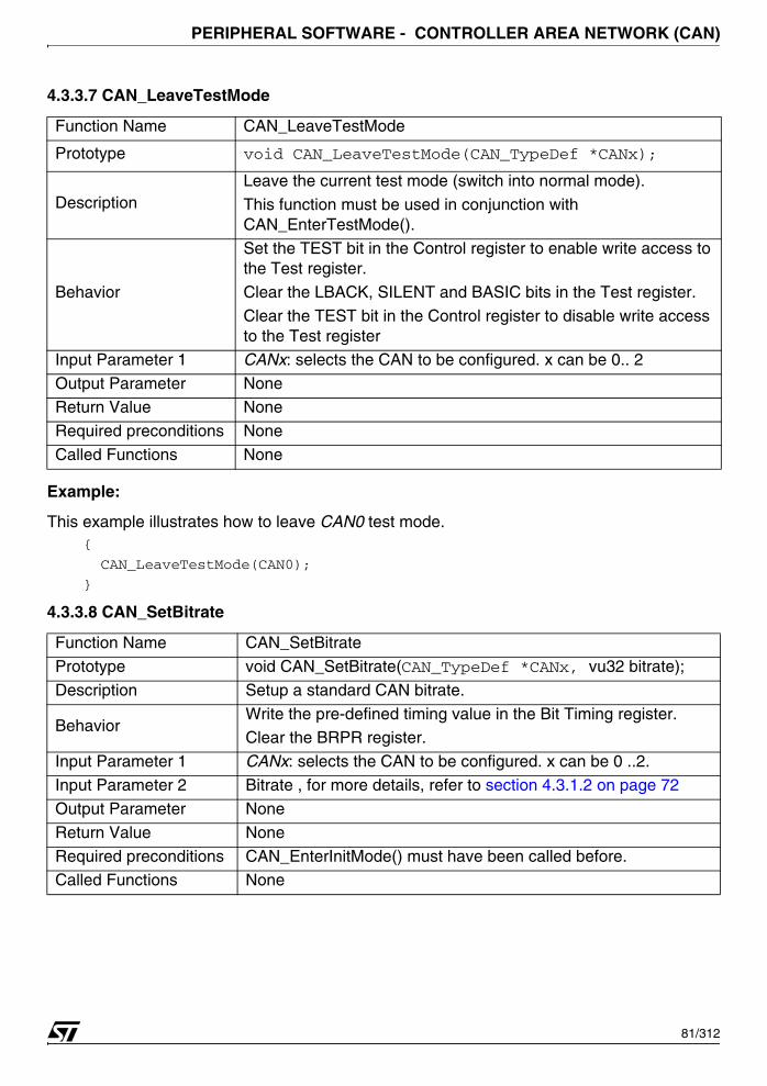
PERIPHERAL SOFTWARE - CONTROLLER AREA NETWORK (CAN)
4.3.3.7 CAN_LeaveTestMode
Example:
This example illustrates how to leave CAN0 test mode.{
CAN_LeaveTestMode(CAN0);
}
4.3.3.8 CAN_SetBitrate
Function Name CAN_LeaveTestMode
Prototype void CAN_LeaveTestMode(CAN_TypeDef *CANx);
DescriptionLeave the current test mode (switch into normal mode).
This function must be used in conjunction with CAN_EnterTestMode().
Behavior
Set the TEST bit in the Control register to enable write access to the Test register.
Clear the LBACK, SILENT and BASIC bits in the Test register.
Clear the TEST bit in the Control register to disable write access to the Test register
Input Parameter 1 CANx: selects the CAN to be configured. x can be 0.. 2
Output Parameter NoneReturn Value None
Required preconditions None
Called Functions None
Function Name CAN_SetBitrate
Prototype void CAN_SetBitrate(CAN_TypeDef *CANx, vu32 bitrate);
Description Setup a standard CAN bitrate.
BehaviorWrite the pre-defined timing value in the Bit Timing register.Clear the BRPR register.
Input Parameter 1 CANx: selects the CAN to be configured. x can be 0 ..2.
Input Parameter 2 Bitrate , for more details, refer to section 4.3.1.2 on page 72
Output Parameter None
Return Value None
Required preconditions CAN_EnterInitMode() must have been called before.Called Functions None
81/312
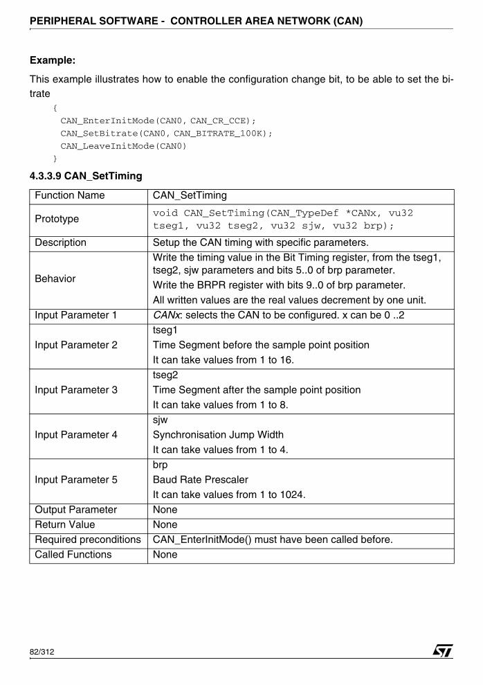
PERIPHERAL SOFTWARE - CONTROLLER AREA NETWORK (CAN)
Example:
This example illustrates how to enable the configuration change bit, to be able to set the bi-trate
{
CAN_EnterInitMode(CAN0, CAN_CR_CCE);
CAN_SetBitrate(CAN0, CAN_BITRATE_100K);
CAN_LeaveInitMode(CAN0)
}
4.3.3.9 CAN_SetTiming
Function Name CAN_SetTiming
Prototypevoid CAN_SetTiming(CAN_TypeDef *CANx, vu32 tseg1, vu32 tseg2, vu32 sjw, vu32 brp);
Description Setup the CAN timing with specific parameters.
Behavior
Write the timing value in the Bit Timing register, from the tseg1, tseg2, sjw parameters and bits 5..0 of brp parameter.
Write the BRPR register with bits 9..0 of brp parameter.
All written values are the real values decrement by one unit.
Input Parameter 1 CANx: selects the CAN to be configured. x can be 0 ..2
Input Parameter 2
tseg1
Time Segment before the sample point position
It can take values from 1 to 16.
Input Parameter 3
tseg2
Time Segment after the sample point position
It can take values from 1 to 8.
Input Parameter 4
sjw
Synchronisation Jump Width
It can take values from 1 to 4.
Input Parameter 5
brp
Baud Rate Prescaler
It can take values from 1 to 1024.
Output Parameter NoneReturn Value None
Required preconditions CAN_EnterInitMode() must have been called before.
Called Functions None
82/312
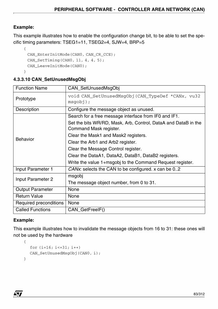
PERIPHERAL SOFTWARE - CONTROLLER AREA NETWORK (CAN)
Example:
This example illustrates how to enable the configuration change bit, to be able to set the spe-cific timing parameters: TSEG1=11, TSEG2=4, SJW=4, BRP=5
{
CAN_EnterInitMode(CAN0, CAN_CR_CCE);
CAN_SetTiming(CAN0, 11, 4, 4, 5);
CAN_LeaveInitMode(CAN0);
}
4.3.3.10 CAN_SetUnusedMsgObj
Example:
This example illustrates how to invalidate the message objects from 16 to 31: these ones willnot be used by the hardware
{
for (i=16; i<=31; i++)
CAN_SetUnusedMsgObj(CAN0, i);
}
Function Name CAN_SetUnusedMsgObj
Prototypevoid CAN_SetUnusedMsgObj(CAN_TypeDef *CANx, vu32 msgobj);
Description Configure the message object as unused.
Behavior
Search for a free message interface from IF0 and IF1.
Set the bits WR/RD, Mask, Arb, Control, DataA and DataB in the Command Mask register.
Clear the Mask1 and Mask2 registers.
Clear the Arb1 and Arb2 register.Clear the Message Control register.
Clear the DataA1, DataA2, DataB1, DataB2 registers.
Write the value 1+msgobj to the Command Request register.
Input Parameter 1 CANx: selects the CAN to be configured. x can be 0..2
Input Parameter 2msgobj
The message object number, from 0 to 31.Output Parameter None
Return Value None
Required preconditions None
Called Functions CAN_GetFreeIF()
83/312
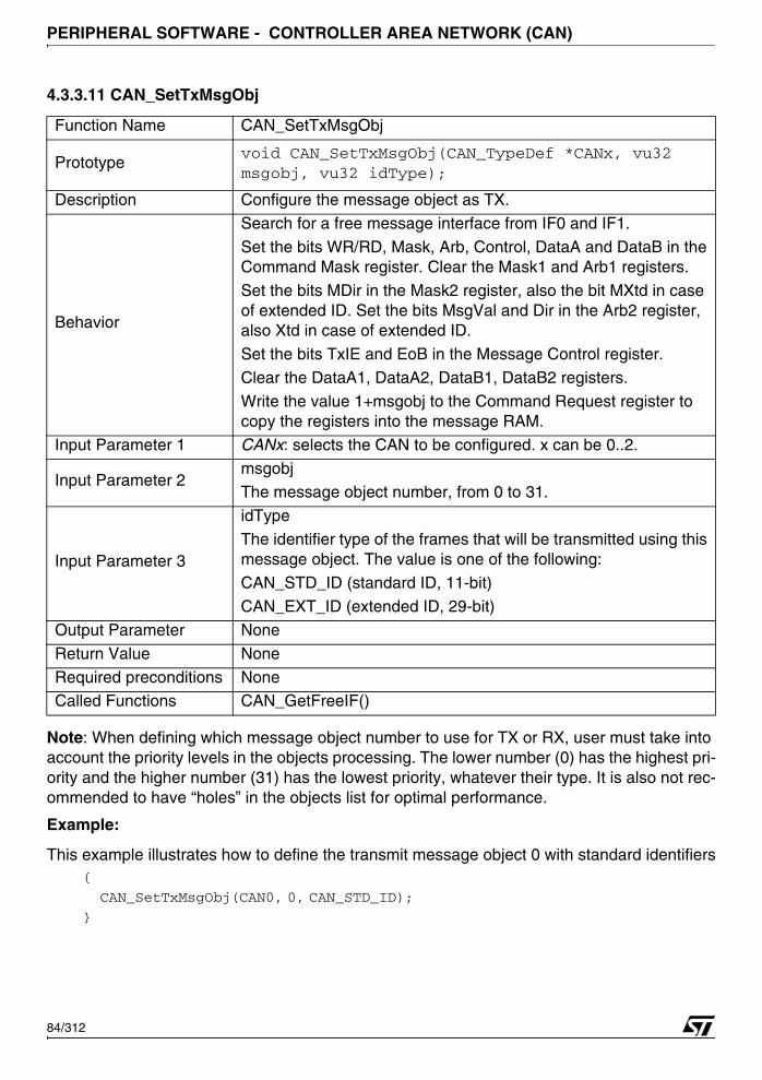
PERIPHERAL SOFTWARE - CONTROLLER AREA NETWORK (CAN)
4.3.3.11 CAN_SetTxMsgObj
Note: When defining which message object number to use for TX or RX, user must take into account the priority levels in the objects processing. The lower number (0) has the highest pri-ority and the higher number (31) has the lowest priority, whatever their type. It is also not rec-ommended to have “holes” in the objects list for optimal performance.
Example:
This example illustrates how to define the transmit message object 0 with standard identifiers{
CAN_SetTxMsgObj(CAN0, 0, CAN_STD_ID);
}
Function Name CAN_SetTxMsgObj
Prototypevoid CAN_SetTxMsgObj(CAN_TypeDef *CANx, vu32 msgobj, vu32 idType);
Description Configure the message object as TX.
Behavior
Search for a free message interface from IF0 and IF1.
Set the bits WR/RD, Mask, Arb, Control, DataA and DataB in the Command Mask register. Clear the Mask1 and Arb1 registers.
Set the bits MDir in the Mask2 register, also the bit MXtd in case of extended ID. Set the bits MsgVal and Dir in the Arb2 register, also Xtd in case of extended ID.
Set the bits TxIE and EoB in the Message Control register.
Clear the DataA1, DataA2, DataB1, DataB2 registers.
Write the value 1+msgobj to the Command Request register to copy the registers into the message RAM.
Input Parameter 1 CANx: selects the CAN to be configured. x can be 0..2.
Input Parameter 2 msgobjThe message object number, from 0 to 31.
Input Parameter 3
idType
The identifier type of the frames that will be transmitted using this message object. The value is one of the following:
CAN_STD_ID (standard ID, 11-bit)
CAN_EXT_ID (extended ID, 29-bit)
Output Parameter None
Return Value None
Required preconditions NoneCalled Functions CAN_GetFreeIF()
84/312
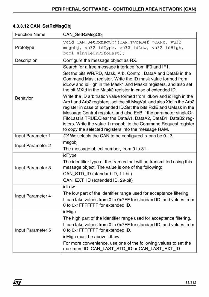
PERIPHERAL SOFTWARE - CONTROLLER AREA NETWORK (CAN)
4.3.3.12 CAN_SetRxMsgObj
Function Name CAN_SetRxMsgObj
Prototypevoid CAN_SetRxMsgObj(CAN_TypeDef *CANx, vu32 msgobj, vu32 idType, vu32 idLow, vu32 idHigh, bool singleOrFifoLast);
Description Configure the message object as RX.
Behavior
Search for a free message interface from IF0 and IF1.
Set the bits WR/RD, Mask, Arb, Control, DataA and DataB in the Command Mask register. Write the ID mask value formed from idLow and idHigh in the Mask1 and Mask2 registers, and also set the bit MXtd in the Mask2 register in case of extended ID.Write the ID arbitration value formed from idLow and idHigh in the Arb1 and Arb2 registers, set the bit MsgVal, and also Xtd in the Arb2 register in case of extended ID.Set the bits RxIE and UMask in the Message Control register, and also EoB if the parameter singleOr-FifoLast is TRUE.Clear the DataA1, DataA2, DataB1, DataB2 reg-isters. Write the value 1+msgobj to the Command Request register to copy the selected registers into the message RAM.
Input Parameter 1 CANx: selects the CAN to be configured. x can be 0.. 2.
Input Parameter 2 msgobj
The message object number, from 0 to 31.
Input Parameter 3
idType
The identifier type of the frames that will be transmitted using this message object. The value is one of the following:
CAN_STD_ID (standard ID, 11-bit)
CAN_EXT_ID (extended ID, 29-bit)
Input Parameter 4
idLow
The low part of the identifier range used for acceptance filtering.
It can take values from 0 to 0x7FF for standard ID, and values from 0 to 0x1FFFFFFF for extended ID.
Input Parameter 5
idHigh
The high part of the identifier range used for acceptance filtering.
It can take values from 0 to 0x7FF for standard ID, and values from 0 to 0x1FFFFFFF for extended ID.
idHigh must be above idLow.
For more convenience, use one of the following values to set the maximum ID: CAN_LAST_STD_ID or CAN_LAST_EXT_ID
85/312
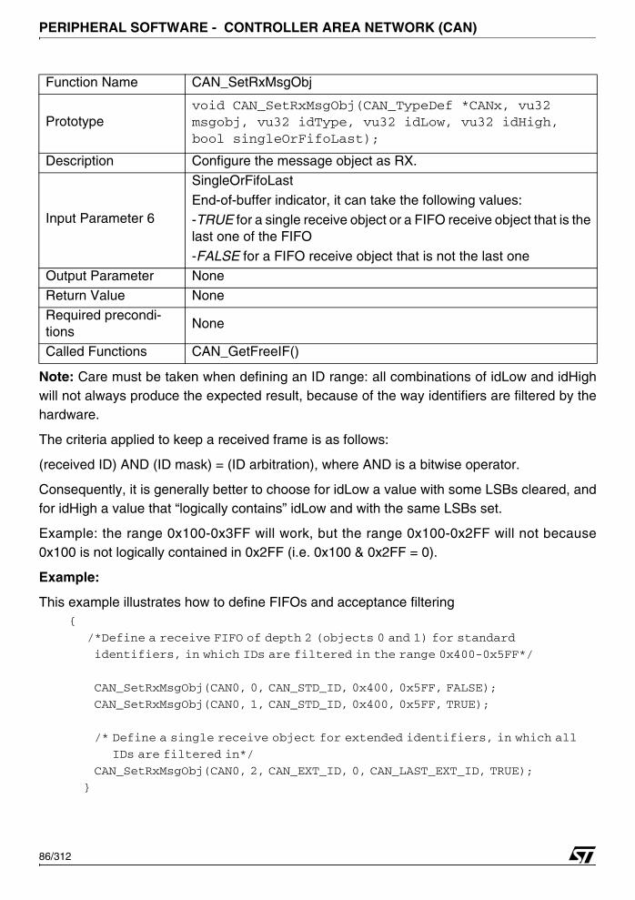
PERIPHERAL SOFTWARE - CONTROLLER AREA NETWORK (CAN)
Note: Care must be taken when defining an ID range: all combinations of idLow and idHighwill not always produce the expected result, because of the way identifiers are filtered by thehardware.
The criteria applied to keep a received frame is as follows:
(received ID) AND (ID mask) = (ID arbitration), where AND is a bitwise operator.
Consequently, it is generally better to choose for idLow a value with some LSBs cleared, andfor idHigh a value that “logically contains” idLow and with the same LSBs set.
Example: the range 0x100-0x3FF will work, but the range 0x100-0x2FF will not because0x100 is not logically contained in 0x2FF (i.e. 0x100 & 0x2FF = 0).
Example:
This example illustrates how to define FIFOs and acceptance filtering{
/*Define a receive FIFO of depth 2 (objects 0 and 1) for standard
identifiers, in which IDs are filtered in the range 0x400-0x5FF*/
CAN_SetRxMsgObj(CAN0, 0, CAN_STD_ID, 0x400, 0x5FF, FALSE);
CAN_SetRxMsgObj(CAN0, 1, CAN_STD_ID, 0x400, 0x5FF, TRUE);
/* Define a single receive object for extended identifiers, in which all
IDs are filtered in*/
CAN_SetRxMsgObj(CAN0, 2, CAN_EXT_ID, 0, CAN_LAST_EXT_ID, TRUE);
}
Input Parameter 6
SingleOrFifoLast
End-of-buffer indicator, it can take the following values:
-TRUE for a single receive object or a FIFO receive object that is the last one of the FIFO
-FALSE for a FIFO receive object that is not the last oneOutput Parameter None
Return Value None
Required precondi-tions
None
Called Functions CAN_GetFreeIF()
Function Name CAN_SetRxMsgObj
Prototypevoid CAN_SetRxMsgObj(CAN_TypeDef *CANx, vu32 msgobj, vu32 idType, vu32 idLow, vu32 idHigh, bool singleOrFifoLast);
Description Configure the message object as RX.
86/312
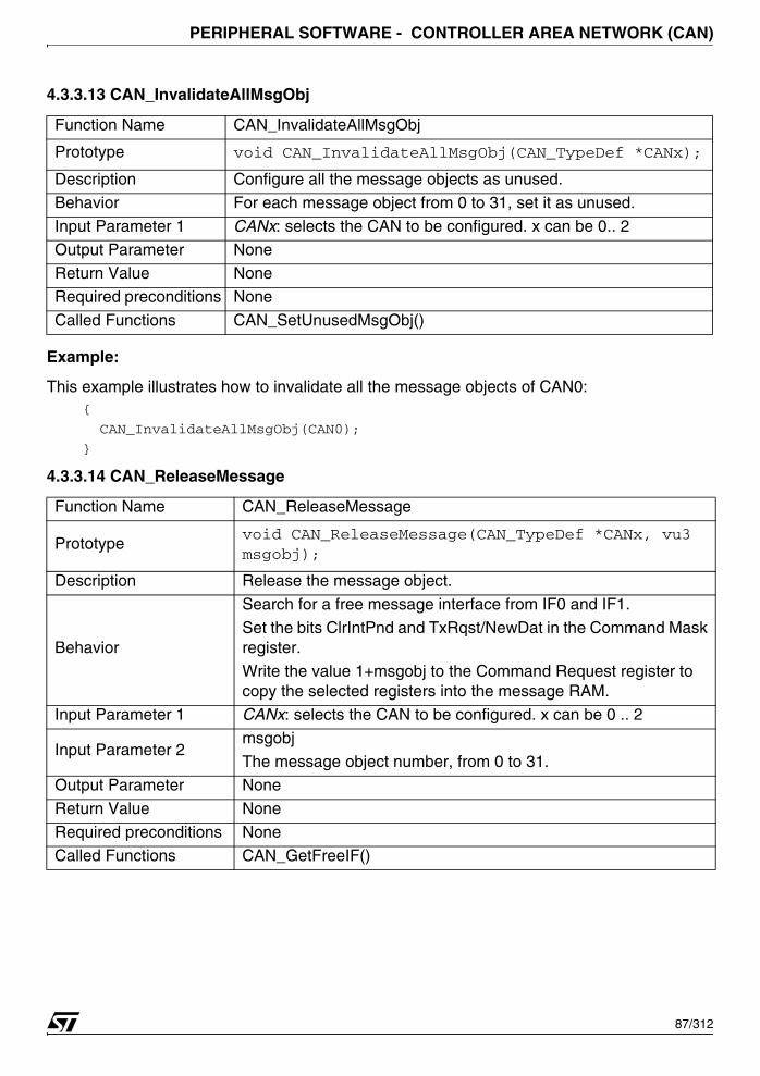
PERIPHERAL SOFTWARE - CONTROLLER AREA NETWORK (CAN)
4.3.3.13 CAN_InvalidateAllMsgObj
Example:
This example illustrates how to invalidate all the message objects of CAN0: {
CAN_InvalidateAllMsgObj(CAN0);
}
4.3.3.14 CAN_ReleaseMessage
Function Name CAN_InvalidateAllMsgObj
Prototype void CAN_InvalidateAllMsgObj(CAN_TypeDef *CANx);
Description Configure all the message objects as unused.
Behavior For each message object from 0 to 31, set it as unused.
Input Parameter 1 CANx: selects the CAN to be configured. x can be 0.. 2
Output Parameter NoneReturn Value None
Required preconditions None
Called Functions CAN_SetUnusedMsgObj()
Function Name CAN_ReleaseMessage
Prototypevoid CAN_ReleaseMessage(CAN_TypeDef *CANx, vu3 msgobj);
Description Release the message object.
Behavior
Search for a free message interface from IF0 and IF1.
Set the bits ClrIntPnd and TxRqst/NewDat in the Command Mask register.
Write the value 1+msgobj to the Command Request register to copy the selected registers into the message RAM.
Input Parameter 1 CANx: selects the CAN to be configured. x can be 0 .. 2
Input Parameter 2msgobj
The message object number, from 0 to 31.Output Parameter None
Return Value None
Required preconditions None
Called Functions CAN_GetFreeIF()
87/312

PERIPHERAL SOFTWARE - CONTROLLER AREA NETWORK (CAN)
Example:
This example illustrates how to release the message object 0.{
CAN_ReleaseMessage(CAN0, 0);
}
4.3.3.15 CAN_ReleaseTxMessage
Example:
This example illustrates how to release the transmit message object 0.{
/* It is assumed that message interface 0 is always used for transmission*/
/* Release the transmit message object 0*/
CAN_ReleaseTxMessage(0);
}
Function Name CAN_ReleaseTxMessage
Prototypevoid CAN_ReleaseTxMessage(CAN_TypeDef *CANx, vu32 msgobj);
Description Release the transmit message object.
Behavior
Set the bits ClrIntPnd and TxRqst/NewDat in the Command Mask register of message interface 0.
Write the value 1+msgobj to the Command Request register to copy the selected registers into the message RAM.
Input Parameter 1 CANx: selects the CAN to be configured. x can be 0.. 2
Input Parameter 2msgobj
The message object number, from 0 to 31.
Output Parameter NoneReturn Value None
Required preconditions The message interface 0 must not be busy.
Called Functions None
88/312
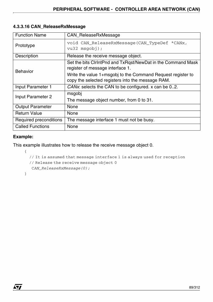
PERIPHERAL SOFTWARE - CONTROLLER AREA NETWORK (CAN)
4.3.3.16 CAN_ReleaseRxMessage
Example:
This example illustrates how to release the receive message object 0. {
// It is assumed that message interface 1 is always used for reception
// Release the receive message object 0
CAN_ReleaseRxMessage(0);
}
Function Name CAN_ReleaseRxMessage
Prototypevoid CAN_ReleaseRxMessage(CAN_TypeDef *CANx, vu32 msgobj);
Description Release the receive message object.
Behavior
Set the bits ClrIntPnd and TxRqst/NewDat in the Command Mask register of message interface 1.
Write the value 1+msgobj to the Command Request register to copy the selected registers into the message RAM.
Input Parameter 1 CANx: selects the CAN to be configured. x can be 0..2.
Input Parameter 2msgobj
The message object number, from 0 to 31.
Output Parameter NoneReturn Value None
Required preconditions The message interface 1 must not be busy.
Called Functions None
89/312

PERIPHERAL SOFTWARE - CONTROLLER AREA NETWORK (CAN)
4.3.3.17 CAN_SendMessage
Example:
This example illustrates how to send a standard ID data frame containing 4 data value. {
canmsg CanMsg = {CAN_STD_ID, 0x111, 4, {0x10, 0x20, 0x40, 0x80}};
/* Send a standard ID data frame containing 4 data values*/
CAN_SendMessage(0, &CanMsg);
}
Function Name CAN_SendMessage
Prototype u32 CAN_SendMessage(CAN_TypeDef *CANx, vu32 msgobj,canmsg* pCanMsg);
Description Start transmission of a message.
Behavior Wait for the message interface 0 to be free.
Read the Arbitration and Message Control registers.
Wait for the message interface 0 to be free.
Update the Arbitration, Message Control, DataA and DataB regis-ters with the message contents.
Write the value 1+msgobj to the Command Request register tocopy the selected registers into the message RAM and to start thetransmission.
Input Parameter 1 CANx: selects the CAN to be configured. x can be 0.. 2.
Input Parameter 2 msgobj
The message object number, from 0 to 31.
Input Parameter 3 pCanMsg
Pointer to the canmsg structure that contains the data to transmit:ID type, ID value, data length, data values.
Output Parameter NoneReturn Value 1 if transmission was OK, else 0
Required preconditions The message object must have been set up properly.
Called Functions None
90/312
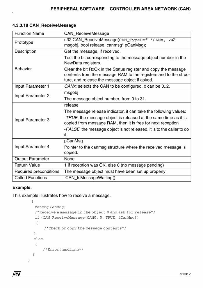
PERIPHERAL SOFTWARE - CONTROLLER AREA NETWORK (CAN)
4.3.3.18 CAN_ReceiveMessage
Example:
This example illustrates how to receive a message. {
canmsg CanMsg;
/*Receive a message in the object 0 and ask for release*/
if (CAN_ReceiveMessage(CAN0, 0, TRUE, &CanMsg))
{
/*Check or copy the message contents*/
}
else
{
/*Error handling*/
}
}
Function Name CAN_ReceiveMessage
Prototypeu32 CAN_ReceiveMessage(CAN_TypeDef *CANx, vu2 msgobj, bool release, canmsg* pCanMsg);
Description Get the message, if received.
Behavior
Test the bit corresponding to the message object number in the NewData registers.
Clear the bit RxOk in the Status register and copy the message contents from the message RAM to the registers and to the struc-ture, and release the message object if asked.
Input Parameter 1 CANx: selects the CAN to be configured. x can be 0..2.
Input Parameter 2msgobj
The message object number, from 0 to 31.
Input Parameter 3
release
The message release indicator, it can take the following values:
-TRUE: the message object is released at the same time as it is copied from message RAM, then it is free for next reception
-FALSE: the message object is not released, it is to the caller to do it
Input Parameter 4pCanMsg
Pointer to the canmsg structure where the received message is copied.
Output Parameter None
Return Value 1 if reception was OK, else 0 (no message pending)
Required preconditions The message object must have been set up properly.
Called Functions CAN_IsMessageWaiting()
91/312

PERIPHERAL SOFTWARE - CONTROLLER AREA NETWORK (CAN)
4.3.3.19 CAN_WaitEndOfTx
Example:
This example illustrates how to send frames.{
/*Send consecutive data frames using message object 0*/
for (i = 0; i < 10; i++)
{
CAN_SendMessage(CAN0, 0, CanMsgTable[i]);
CAN_WaitEndOfTx(CAN0);
}
}
Function Name CAN_WaitEndOfTx
Prototype void CAN_WaitEndOfTx(CAN_TypeDef *CANx);
Description
Wait until current transmission is finished.
This function should be called between two consecutive transmis-sions to ensure the latest frame has been completely emitted on the bus, and therefore cannot be aborted anymore.
BehaviorTest the bit TxOk in the Status register, and loop until it is set.
Clear this bit to prepare the next transmission.
Input Parameter 1 CANx: selects the CAN to be configured. x can be 0..2.
Output Parameter NoneReturn Value None
Required preconditions A message must have been sent before.
Called Functions None
92/312
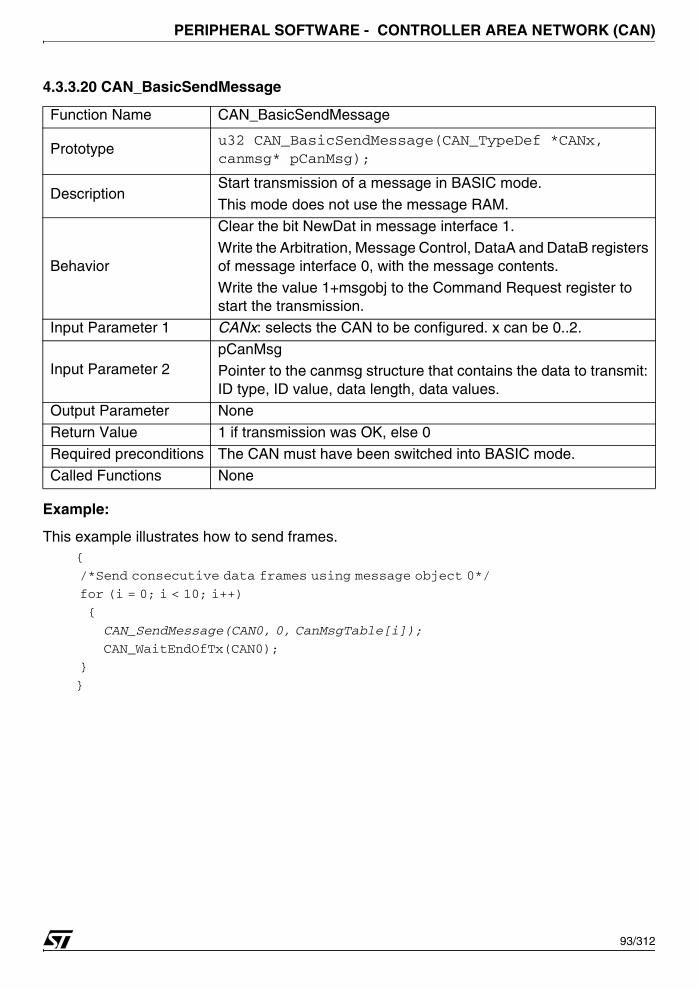
PERIPHERAL SOFTWARE - CONTROLLER AREA NETWORK (CAN)
4.3.3.20 CAN_BasicSendMessage
Example:
This example illustrates how to send frames.{
/*Send consecutive data frames using message object 0*/
for (i = 0; i < 10; i++)
{
CAN_SendMessage(CAN0, 0, CanMsgTable[i]);
CAN_WaitEndOfTx(CAN0);
}
}
Function Name CAN_BasicSendMessage
Prototypeu32 CAN_BasicSendMessage(CAN_TypeDef *CANx, canmsg* pCanMsg);
DescriptionStart transmission of a message in BASIC mode.
This mode does not use the message RAM.
Behavior
Clear the bit NewDat in message interface 1.
Write the Arbitration, Message Control, DataA and DataB registers of message interface 0, with the message contents.
Write the value 1+msgobj to the Command Request register to start the transmission.
Input Parameter 1 CANx: selects the CAN to be configured. x can be 0..2.
Input Parameter 2pCanMsgPointer to the canmsg structure that contains the data to transmit: ID type, ID value, data length, data values.
Output Parameter None
Return Value 1 if transmission was OK, else 0
Required preconditions The CAN must have been switched into BASIC mode.
Called Functions None
93/312
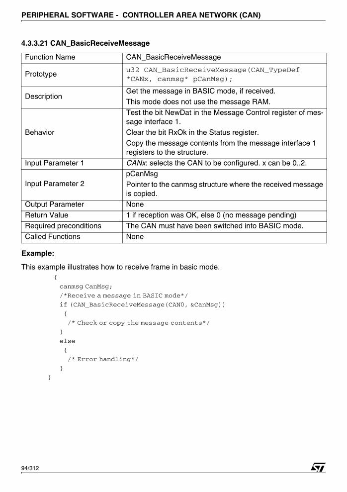
PERIPHERAL SOFTWARE - CONTROLLER AREA NETWORK (CAN)
4.3.3.21 CAN_BasicReceiveMessage
Example:
This example illustrates how to receive frame in basic mode. {
canmsg CanMsg;
/*Receive a message in BASIC mode*/
if (CAN_BasicReceiveMessage(CAN0, &CanMsg))
{
/* Check or copy the message contents*/
}
else
{
/* Error handling*/
}
}
Function Name CAN_BasicReceiveMessage
Prototypeu32 CAN_BasicReceiveMessage(CAN_TypeDef *CANx, canmsg* pCanMsg);
DescriptionGet the message in BASIC mode, if received.
This mode does not use the message RAM.
Behavior
Test the bit NewDat in the Message Control register of mes-sage interface 1.
Clear the bit RxOk in the Status register.
Copy the message contents from the message interface 1 registers to the structure.
Input Parameter 1 CANx: selects the CAN to be configured. x can be 0..2.
Input Parameter 2pCanMsgPointer to the canmsg structure where the received message is copied.
Output Parameter None
Return Value 1 if reception was OK, else 0 (no message pending)
Required preconditions The CAN must have been switched into BASIC mode.
Called Functions None
94/312
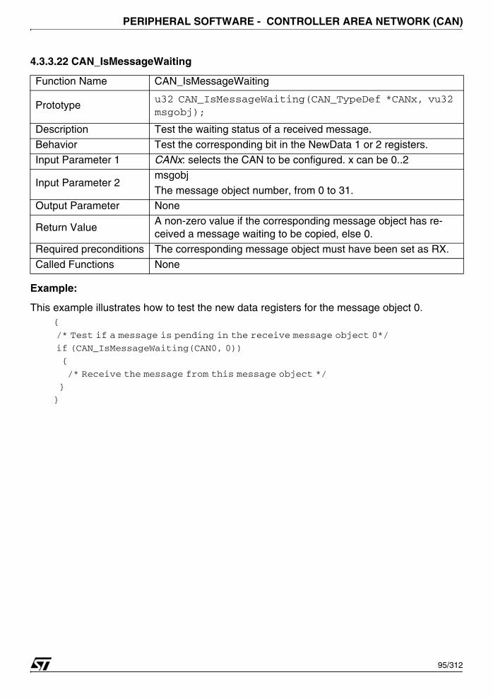
PERIPHERAL SOFTWARE - CONTROLLER AREA NETWORK (CAN)
4.3.3.22 CAN_IsMessageWaiting
Example:
This example illustrates how to test the new data registers for the message object 0.{
/* Test if a message is pending in the receive message object 0*/
if (CAN_IsMessageWaiting(CAN0, 0))
{
/* Receive the message from this message object */
}
}
Function Name CAN_IsMessageWaiting
Prototypeu32 CAN_IsMessageWaiting(CAN_TypeDef *CANx, vu32 msgobj);
Description Test the waiting status of a received message.
Behavior Test the corresponding bit in the NewData 1 or 2 registers.
Input Parameter 1 CANx: selects the CAN to be configured. x can be 0..2
Input Parameter 2msgobj
The message object number, from 0 to 31.Output Parameter None
Return Value A non-zero value if the corresponding message object has re-ceived a message waiting to be copied, else 0.
Required preconditions The corresponding message object must have been set as RX.
Called Functions None
95/312
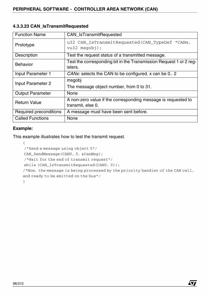
PERIPHERAL SOFTWARE - CONTROLLER AREA NETWORK (CAN)
4.3.3.23 CAN_IsTransmitRequested
Example:
This example illustrates how to test the transmit request.{
/*Send a message using object 0*/
CAN_SendMessage(CAN0, 0, &CanMsg);
/*Wait for the end of transmit request*/
while (CAN_IsTransmitRequested(CAN0, 0));
/*Now, the message is being processed by the priority handler of the CAN cell,
and ready to be emitted on the bus*/
}
Function Name CAN_IsTransmitRequested
Prototypeu32 CAN_IsTransmitRequested(CAN_TypeDef *CANx, vu32 msgobj);
Description Test the request status of a transmitted message.
BehaviorTest the corresponding bit in the Transmission Request 1 or 2 reg-isters.
Input Parameter 1 CANx: selects the CAN to be configured. x can be 0.. 2
Input Parameter 2msgobj
The message object number, from 0 to 31.
Output Parameter None
Return Value A non-zero value if the corresponding message is requested to transmit, else 0.
Required preconditions A message must have been sent before.
Called Functions None
96/312
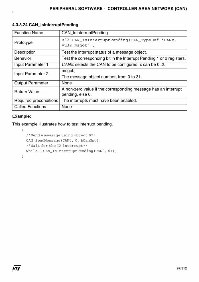
PERIPHERAL SOFTWARE - CONTROLLER AREA NETWORK (CAN)
4.3.3.24 CAN_IsInterruptPending
Example:
This example illustrates how to test interrupt pending.{
/*Send a message using object 0*/
CAN_SendMessage(CAN0, 0, &CanMsg);
/*Wait for the TX interrupt*/
while (!CAN_IsInterruptPending(CAN0, 0));
}
Function Name CAN_IsInterruptPending
Prototypeu32 CAN_IsInterruptPending(CAN_TypeDef *CANx, vu32 msgobj);
Description Test the interrupt status of a message object.
Behavior Test the corresponding bit in the Interrupt Pending 1 or 2 registers.
Input Parameter 1 CANx: selects the CAN to be configured. x can be 0..2.
Input Parameter 2msgobj
The message object number, from 0 to 31.Output Parameter None
Return Value A non-zero value if the corresponding message has an interrupt pending, else 0.
Required preconditions The interrupts must have been enabled.
Called Functions None
97/312
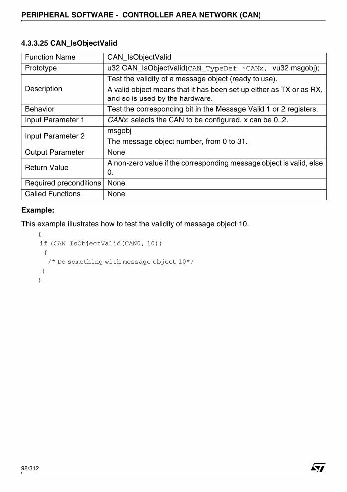
PERIPHERAL SOFTWARE - CONTROLLER AREA NETWORK (CAN)
4.3.3.25 CAN_IsObjectValid
Example:
This example illustrates how to test the validity of message object 10.{
if (CAN_IsObjectValid(CAN0, 10))
{
/* Do something with message object 10*/
}
}
Function Name CAN_IsObjectValid
Prototype u32 CAN_IsObjectValid(CAN_TypeDef *CANx, vu32 msgobj);
DescriptionTest the validity of a message object (ready to use).
A valid object means that it has been set up either as TX or as RX, and so is used by the hardware.
Behavior Test the corresponding bit in the Message Valid 1 or 2 registers.Input Parameter 1 CANx: selects the CAN to be configured. x can be 0..2.
Input Parameter 2msgobj
The message object number, from 0 to 31.
Output Parameter None
Return Value A non-zero value if the corresponding message object is valid, else 0.
Required preconditions None
Called Functions None
98/312

PERIPHERAL SOFTWARE - CONFIGURATION REGISTER (CFG)
4.4 CONFIGURATION REGISTER (CFG)
The CFG driver may be used to manage the system configuration registers in configuringsome critical STR73x features, enabling or disabling reset and clock lines for each peripheraland also it reports the status of the system.
The first section describes the data structures used in the CFG software library. The secondone presents the software library functions.
4.4.1 Data structures
4.4.1.1 CFG Register structure
The CFG registers structure CFG_TypeDef is defined in the 73x_map.h file as follows:typedef struct
{
vu32 R0;
vu32 EITE0;
vu32 PCGR0;
vu32 PCGR1;
vu32 PECGR0;
vu32 PECGR1;
vu32 PCGRB0;
vu32 PCGRB1;
vu32 TIMSR;
vu32 EITE1;
vu32 EITE2;
vu32 ESPR;
vu32 R1;
vuc32 DIDR;
}CFG_TypeDef;
The following table presents the BSPI registers:
Register DescriptionR0 Configuration Register 0
EITE0 External Interrupt Trigger Event Register 0PCGR0 Peripheral Clock Gating Register 0
PCGR1 Peripheral Clock Gating Register 1
PECGR0 Peripheral Emulation Clock Gating Register 0
PECGR1 Peripheral Emulation Clock Gating Register 1
PCGRB0 Peripheral Clock Gating Register B0
PCGRB1 Peripheral Clock Gating Register B1TIMSR TIM External Clock Select Register
99/312

PERIPHERAL SOFTWARE - CONFIGURATION REGISTER (CFG)
The CFG interface is declared in the same file:...
#define CFG_BASE 0x40000000
...
#ifndef DEBUG
...
#define CFG ((CFG_TypeDef *) CFG_BASE)
...
#else
...
EXT CFG_TypeDef *CFG
...
#endif
When debug mode is used, CFG pointer is initialized in 73x_lib.c file:
#ifdef _CFG
CFG = (CFG_TypeDef *)CFG_BASE;
#endif /*_CFG */
_CFG must be defined, in 73x_conf.h file, to access the peripheral registers as follows :#define _CFG
...
Note: It is recommended to declare this define in all projects since CFG is used in most of alluser applications.
Note: Since the CFG peripheral is very critical and it defines the global configuration of the de-vice, the CFG Software library is slightly different from the whole library: There are nor struc-ture definition neither a structure initialization and CFG de-initialization. So user must takecare of how to enable or disable a specific feature using the functions described in the fol-lowing sections.
Note: Some CFG bit features are enabled or disabled in others Software peripheral libraries,such as DMA transfer, flash, EIC etc.
EITE1 External Interrupt Trigger Event Register 1EITE1 External Interrupt Trigger Event Register 2
ESPR Emulation Serial Protection Register
R1 Configuration Register 1
DIDR Device Identification Register
Register Description
100/312
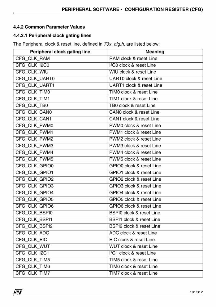
PERIPHERAL SOFTWARE - CONFIGURATION REGISTER (CFG)
4.4.2 Common Parameter Values
4.4.2.1 Peripheral clock gating lines
The Peripheral clock & reset line, defined in 73x_cfg.h, are listed below:
Peripheral clock gating line MeaningCFG_CLK_RAM RAM clock & reset Line
CFG_CLK_I2C0 I²C0 clock & reset Line
CFG_CLK_WIU WIU clock & reset LineCFG_CLK_UART0 UART0 clock & reset Line
CFG_CLK_UART1 UART1 clock & reset Line
CFG_CLK_TIM0 TIM0 clock & reset Line
CFG_CLK_TIM1 TIM1 clock & reset Line
CFG_CLK_TB0 TB0 clock & reset Line
CFG_CLK_CAN0 CAN0 clock & reset LineCFG_CLK_CAN1 CAN1 clock & reset Line
CFG_CLK_PWM0 PWM0 clock & reset Line
CFG_CLK_PWM1 PWM1 clock & reset Line
CFG_CLK_PWM2 PWM2 clock & reset Line
CFG_CLK_PWM3 PWM3 clock & reset Line
CFG_CLK_PWM4 PWM4 clock & reset Line
CFG_CLK_PWM5 PWM5 clock & reset LineCFG_CLK_GPIO0 GPIO0 clock & reset Line
CFG_CLK_GPIO1 GPIO1 clock & reset Line
CFG_CLK_GPIO2 GPIO2 clock & reset Line
CFG_CLK_GPIO3 GPIO3 clock & reset Line
CFG_CLK_GPIO4 GPIO4 clock & reset Line
CFG_CLK_GPIO5 GPIO5 clock & reset LineCFG_CLK_GPIO6 GPIO6 clock & reset Line
CFG_CLK_BSPI0 BSPI0 clock & reset Line
CFG_CLK_BSPI1 BSPI1 clock & reset Line
CFG_CLK_BSPI2 BSPI2 clock & reset Line
CFG_CLK_ADC ADC clock & reset Line
CFG_CLK_EIC EIC clock & reset Line
CFG_CLK_WUT WUT clock & reset LineCFG_CLK_I2C1 I²C1 clock & reset Line
CFG_CLK_TIM5 TIM5 clock & reset Line
CFG_CLK_TIM6 TIM6 clock & reset Line
CFG_CLK_TIM7 TIM7 clock & reset Line
101/312

PERIPHERAL SOFTWARE - CONFIGURATION REGISTER (CFG)
4.4.2.2 CFG flags
The CFG flags, defined in 73x_cfg.h, are listed below:
4.4.2.3 CFG MEM Remap
The CFG flags, defined in 73x_cfg.h, are listed below:
CFG_CLK_TIM8 TIM8 clock & reset LineCFG_CLK_TIM9 TIM9 clock & reset Line
CFG_CLK_UART2 UART2 clock & reset Line
CFG_CLK_UART3 UART3 clock & reset Line
CFG_CLK_TB1 ITB1 clock & reset Line
CFG_CLK_TB2 TB2 clock & reset Line
CFG_CLK_CAN2 CAN2 clock & reset LineCFG_CLK_TIM2 TIM2 clock & reset Line
CFG_CLK_TIM3 TIM3 clock & reset Line
CFG_CLK_TIM4 TIM4 clock & reset Line
CFG_CLK_RTC RTC clock & reset Line
CFG_CLK_DMA0 DMA0 clock & reset Line
CFG_CLK_DMA1 DMA1 clock & reset LineCFG_CLK_DMA2 DMA2 clock & reset Line
CFG_CLK_DMA3 DMA3 clock & reset Line
CFG_CLK_NativeBusArbiter NativeBusArbiter clock & reset Line
CFG_CLK_AHBArbiter AHBArbiter clock & reset Line
CFG flags MeaningCFG_FLAG_SYS SystemMemory Mode flag
CFG_FLAG_BOOT Boot mode flag
CFG_FLAG_USER1 User 1 mode flag
CFG_FLAG_USER2 User 2 mode flagCFG_FLAG_JTBT JTAG Boot Mode flag
CFG MEM Remap MeaningCFG_MEM_RAM Remap RAM at address 0hCFG_MEM_FLASH Remap Flash at address 0h
Peripheral clock gating line Meaning
102/312
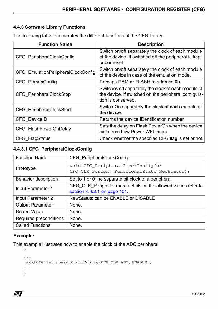
PERIPHERAL SOFTWARE - CONFIGURATION REGISTER (CFG)
4.4.3 Software Library Functions
The following table enumerates the different functions of the CFG library.
4.4.3.1 CFG_PeripheralClockConfig
Example:
This example illustrates how to enable the clock of the ADC peripheral{
...
void CFG_PeripheralClockConfig(CFG_CLK_ADC, ENABLE);
...
}
Function Name Description
CFG_PeripheralClockConfigSwitch on/off separately the clock of each module of the device. If switched off the peripheral is kept under reset
CFG_EmulationPeripheralClockConfigSwitch on/off separately the clock of each module of the device in case of the emulation mode.
CFG_RemapConfig Remaps RAM or FLASH to address 0h.
CFG_PeripheralClockStopSwitches off separately the clock of each module of the device. if switched off the peripheral configura-tion is conserved.
CFG_PeripheralClockStartSwitch On separately the clock of each module of the device.
CFG_DeviceID Returns the device IDentification number
CFG_FlashPowerOnDelaySets the delay on Flash PowerOn when the device exits from Low Power WFI mode
CFG_FlagStatus Check whether the specified CFG flag is set or not.
Function Name CFG_PeripheralClockConfig
Prototypevoid CFG_PeripheralClockConfig(u8 CFG_CLK_Periph, FunctionalState NewStatus);
Behavior description Set to 1 or 0 the separate bit clock of a peripheral.
Input Parameter 1CFG_CLK_Periph: for more details on the allowed values refer to section 4.4.2.1 on page 101.
Input Parameter 2 NewStatus: can be ENABLE or DISABLEOutput Parameter None.
Return Value None.
Required preconditions None.
Called Functions None.
103/312
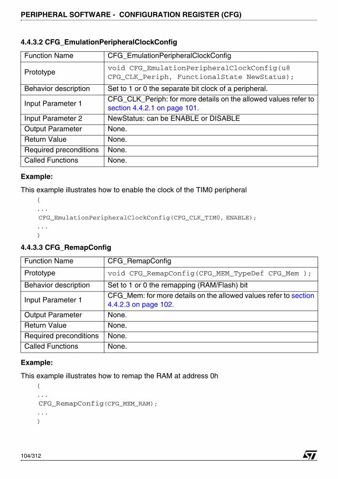
PERIPHERAL SOFTWARE - CONFIGURATION REGISTER (CFG)
4.4.3.2 CFG_EmulationPeripheralClockConfig
Example:
This example illustrates how to enable the clock of the TIM0 peripheral{
...
CFG_EmulationPeripheralClockConfig(CFG_CLK_TIM0, ENABLE);
...
}
4.4.3.3 CFG_RemapConfig
Example:
This example illustrates how to remap the RAM at address 0h{
...
CFG_RemapConfig(CFG_MEM_RAM);...
}
Function Name CFG_EmulationPeripheralClockConfig
Prototypevoid CFG_EmulationPeripheralClockConfig(u8 CFG_CLK_Periph, FunctionalState NewStatus);
Behavior description Set to 1 or 0 the separate bit clock of a peripheral.
Input Parameter 1CFG_CLK_Periph: for more details on the allowed values refer to section 4.4.2.1 on page 101.
Input Parameter 2 NewStatus: can be ENABLE or DISABLE
Output Parameter None.
Return Value None.
Required preconditions None.Called Functions None.
Function Name CFG_RemapConfig
Prototype void CFG_RemapConfig(CFG_MEM_TypeDef CFG_Mem );
Behavior description Set to 1 or 0 the remapping (RAM/Flash) bit
Input Parameter 1CFG_Mem: for more details on the allowed values refer to section 4.4.2.3 on page 102.
Output Parameter None.Return Value None.
Required preconditions None.
Called Functions None.
104/312

PERIPHERAL SOFTWARE - CONFIGURATION REGISTER (CFG)
4.4.3.4 CFG_PeripheralClockStop
Example:
This example illustrates how to stop the clock of the TIM1 peripheral{
...
CFG_PeripheralClockStop(CFG_CLK_TIM1);
...
}
4.4.3.5 CFG_PeripheralClockStart
Example:
This example illustrates how to start the clock of the TIM1 peripheral, already stopped.{
...
CFG_PeripheralClockStart(CFG_CLK_TIM1);
...
}
Function Name CFG_PeripheralClockStop
Prototype void CFG_PeripheralClockStop(u8 CFG_CLK_Periph);
Behavior description Set to 1 the separate bit clock of a peripheral.
Input Parameter 1CFG_CLK_Periph: for more details on the allowed values refer to section 4.4.2.1 on page 101.
Output Parameter None.
Return Value None.
Required preconditions None.Called Functions None.
Function Name CFG_PeripheralClockStart
Prototype void CFG_PeripheralClockStart(u8 CFG_CLK_Periph);
Behavior description Set to 0 the separate bit clock of a peripheral.
Input Parameter 1CFG_CLK_Periph: for more details on the allowed values refer to section 4.4.2.1 on page 101.
Output Parameter None.Return Value None.
Required preconditions None.
Called Functions None.
105/312
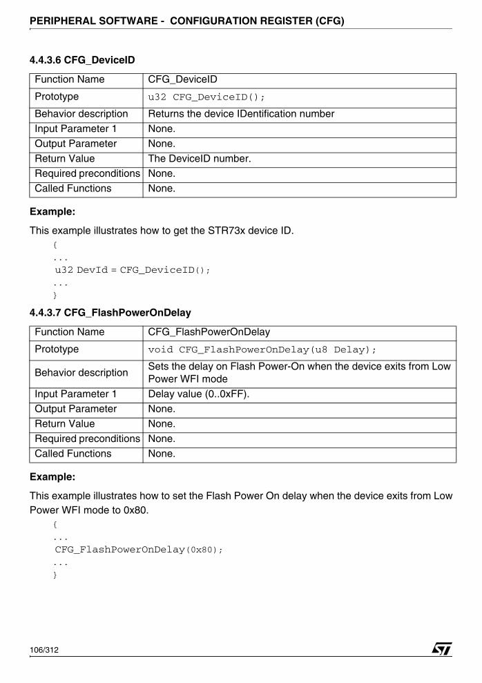
PERIPHERAL SOFTWARE - CONFIGURATION REGISTER (CFG)
4.4.3.6 CFG_DeviceID
Example:
This example illustrates how to get the STR73x device ID.{
...
u32 DevId = CFG_DeviceID();...
}
4.4.3.7 CFG_FlashPowerOnDelay
Example:
This example illustrates how to set the Flash Power On delay when the device exits from LowPower WFI mode to 0x80.
{
...
CFG_FlashPowerOnDelay(0x80);...
}
Function Name CFG_DeviceID
Prototype u32 CFG_DeviceID();
Behavior description Returns the device IDentification number
Input Parameter 1 None.
Output Parameter None.
Return Value The DeviceID number.Required preconditions None.
Called Functions None.
Function Name CFG_FlashPowerOnDelay
Prototype void CFG_FlashPowerOnDelay(u8 Delay);
Behavior descriptionSets the delay on Flash Power-On when the device exits from Low Power WFI mode
Input Parameter 1 Delay value (0..0xFF).Output Parameter None.
Return Value None.
Required preconditions None.
Called Functions None.
106/312

PERIPHERAL SOFTWARE - CONFIGURATION REGISTER (CFG)
4.4.3.8 CFG_FlagStatus
Example:
The following example illustrates how to test CFG User 1 Boot flag is set or not.{
FlagStatus Status;
Status = CFG_FlagStatus(CFG_FLAG_USER1);
}
Function Name CFG_FlagStatus
Function Prototype FlagStatus CFG_FlagStatus (u16 BSPI_Flag)
Description Checks whether the specified CFG flag is set or not.
Input Parameter 1CFG_Flag: flag to check.
Refer to section 4.4.2.2 on page 102 for more details on the al-lowed values of this parameter.
Output Parameter None
Return ParametersThe status of the flag in FlagStatus type, the available value are: SET: if the flag to check is set.
RESET: if the flag to check is reset.
Required Preconditions None
Called Functions None
107/312
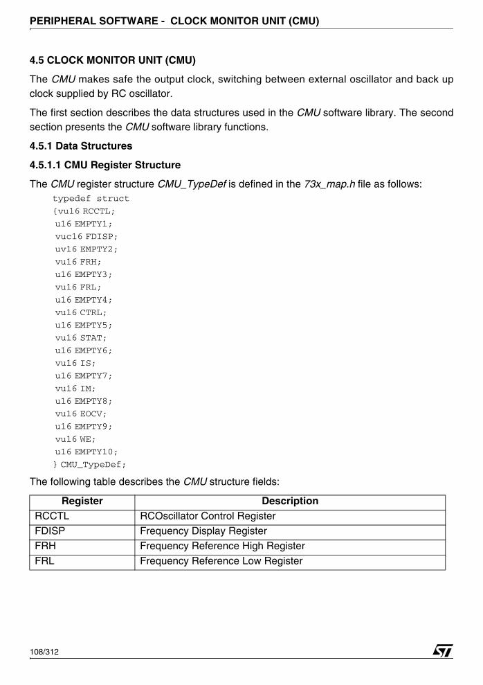
PERIPHERAL SOFTWARE - CLOCK MONITOR UNIT (CMU)
4.5 CLOCK MONITOR UNIT (CMU)
The CMU makes safe the output clock, switching between external oscillator and back upclock supplied by RC oscillator.
The first section describes the data structures used in the CMU software library. The secondsection presents the CMU software library functions.
4.5.1 Data Structures
4.5.1.1 CMU Register Structure
The CMU register structure CMU_TypeDef is defined in the 73x_map.h file as follows:typedef struct
{vu16 RCCTL;
u16 EMPTY1;
vuc16 FDISP;
uv16 EMPTY2;
vu16 FRH;
u16 EMPTY3;
vu16 FRL;
u16 EMPTY4;
vu16 CTRL;
u16 EMPTY5;
vu16 STAT;
u16 EMPTY6;
vu16 IS;
u16 EMPTY7;
vu16 IM;
u16 EMPTY8;
vu16 EOCV;
u16 EMPTY9;
vu16 WE;
u16 EMPTY10;
} CMU_TypeDef;
The following table describes the CMU structure fields:
Register DescriptionRCCTL RCOscillator Control Register
FDISP Frequency Display Register
FRH Frequency Reference High Register
FRL Frequency Reference Low Register
108/312
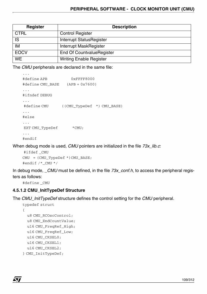
PERIPHERAL SOFTWARE - CLOCK MONITOR UNIT (CMU)
The CMU peripherals are declared in the same file:...
#define APB 0xFFFF8000
#define CMU_BASE (APB + 0x7600)
...
#ifndef DEBUG
...
#define CMU ((CMU_TypeDef *) CMU_BASE)
...
#else
...
EXT CMU_TypeDef *CMU;
...
#endif
When debug mode is used, CMU pointers are initialized in the file 73x_lib.c: #ifdef _CMU
CMU = (CMU_TypeDef *)CMU_BASE;
#endif /*_CMU */
In debug mode, _CMU must be defined, in the file 73x_conf.h, to access the peripheral regis-ters as follows:
#define _CMU
4.5.1.2 CMU_InitTypeDef Structure
The CMU_InitTypeDef structure defines the control setting for the CMU peripheral.typedef struct
{
u8 CMU_RCOscControl;
u8 CMU_EndCountValue;
u16 CMU_FreqRef_High;
u16 CMU_FreqRef_Low;
u16 CMU_CKSEL0;
u16 CMU_CKSEL1;
u16 CMU_CKSEL2;
} CMU_InitTypeDef;
CTRL Control RegisterIS Interrupt StatusRegister
IM Interrupt MaskRegister
EOCV End Of CountvalueRegister
WE Writing Enable Register
Register Description
109/312
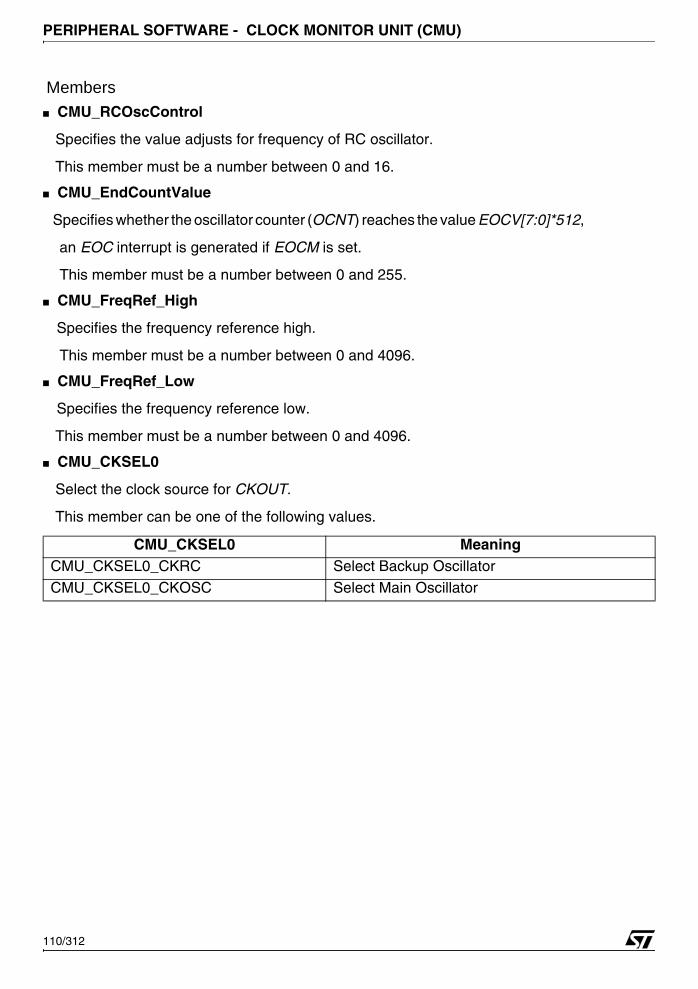
PERIPHERAL SOFTWARE - CLOCK MONITOR UNIT (CMU)
Members■ CMU_RCOscControl
Specifies the value adjusts for frequency of RC oscillator.
This member must be a number between 0 and 16.
■ CMU_EndCountValue
Specifies whether the oscillator counter (OCNT) reaches the value EOCV[7:0]*512,
an EOC interrupt is generated if EOCM is set.
This member must be a number between 0 and 255.
■ CMU_FreqRef_High
Specifies the frequency reference high.
This member must be a number between 0 and 4096.
■ CMU_FreqRef_Low
Specifies the frequency reference low.
This member must be a number between 0 and 4096.
■ CMU_CKSEL0
Select the clock source for CKOUT.
This member can be one of the following values.
CMU_CKSEL0 MeaningCMU_CKSEL0_CKRC Select Backup Oscillator
CMU_CKSEL0_CKOSC Select Main Oscillator
110/312
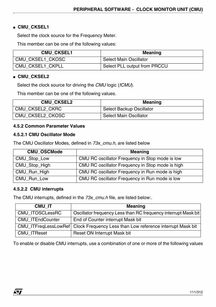
PERIPHERAL SOFTWARE - CLOCK MONITOR UNIT (CMU)
■ CMU_CKSEL1
Select the clock source for the Frequency Meter.
This member can be one of the following values:
■ CMU_CKSEL2
Select the clock source for driving the CMU logic (fCMU).
This member can be one of the following values.
4.5.2 Common Parameter Values
4.5.2.1 CMU Oscillator Mode
The CMU Oscillator Modes, defined in 73x_cmu.h, are listed below
4.5.2.2 CMU interrupts
The CMU interrupts, defined in the 73x_cmu.h file, are listed below:.
To enable or disable CMU interrupts, use a combination of one or more of the following values
CMU_CKSEL1 MeaningCMU_CKSEL1_CKOSC Select Main Oscillator
CMU_CKSEL1_CKPLL Select PLL output from PRCCU
CMU_CKSEL2 MeaningCMU_CKSEL2_CKRC Select Backup Oscillator
CMU_CKSEL2_CKOSC Select Main Oscillator
CMU_OSCMode MeaningCMU_Stop_Low CMU RC oscillator Frequency in Stop mode is lowCMU_Stop_High CMU RC oscillator Frequency in Stop mode is high
CMU_Run_High CMU RC oscillator Frequency in Run mode is high
CMU_Run_Low CMU RC oscillator Frequency in Run mode is low
CMU_IT MeaningCMU_ITOSCLessRC Oscillator frequency Less than RC frequency interrupt Mask bitCMU_ITEndCounter End of Counter interrupt Mask bit
CMU_ITFreqLessLowRef Clock Frequency Less than Low reference interrupt Mask bit
CMU_ITReset Reset ON Interrupt Mask bit
111/312
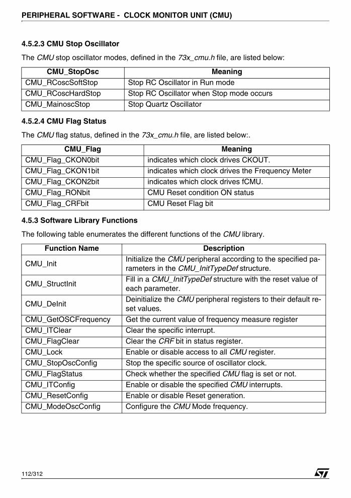
PERIPHERAL SOFTWARE - CLOCK MONITOR UNIT (CMU)
4.5.2.3 CMU Stop Oscillator
The CMU stop oscillator modes, defined in the 73x_cmu.h file, are listed below:
4.5.2.4 CMU Flag Status
The CMU flag status, defined in the 73x_cmu.h file, are listed below:.
4.5.3 Software Library Functions
The following table enumerates the different functions of the CMU library.
CMU_StopOsc MeaningCMU_RCoscSoftStop Stop RC Oscillator in Run modeCMU_RCoscHardStop Stop RC Oscillator when Stop mode occurs
CMU_MainoscStop Stop Quartz Oscillator
CMU_Flag MeaningCMU_Flag_CKON0bit indicates which clock drives CKOUT.
CMU_Flag_CKON1bit indicates which clock drives the Frequency MeterCMU_Flag_CKON2bit indicates which clock drives fCMU.
CMU_Flag_RONbit CMU Reset condition ON status
CMU_Flag_CRFbit CMU Reset Flag bit
Function Name Description
CMU_InitInitialize the CMU peripheral according to the specified pa-rameters in the CMU_InitTypeDef structure.
CMU_StructInitFill in a CMU_InitTypeDef structure with the reset value of each parameter.
CMU_DeInitDeinitialize the CMU peripheral registers to their default re-set values.
CMU_GetOSCFrequency Get the current value of frequency measure registerCMU_ITClear Clear the specific interrupt.
CMU_FlagClear Clear the CRF bit in status register.
CMU_Lock Enable or disable access to all CMU register.
CMU_StopOscConfig Stop the specific source of oscillator clock.
CMU_FlagStatus Check whether the specified CMU flag is set or not.
CMU_ITConfig Enable or disable the specified CMU interrupts.
CMU_ResetConfig Enable or disable Reset generation.CMU_ModeOscConfig Configure the CMU Mode frequency.
112/312
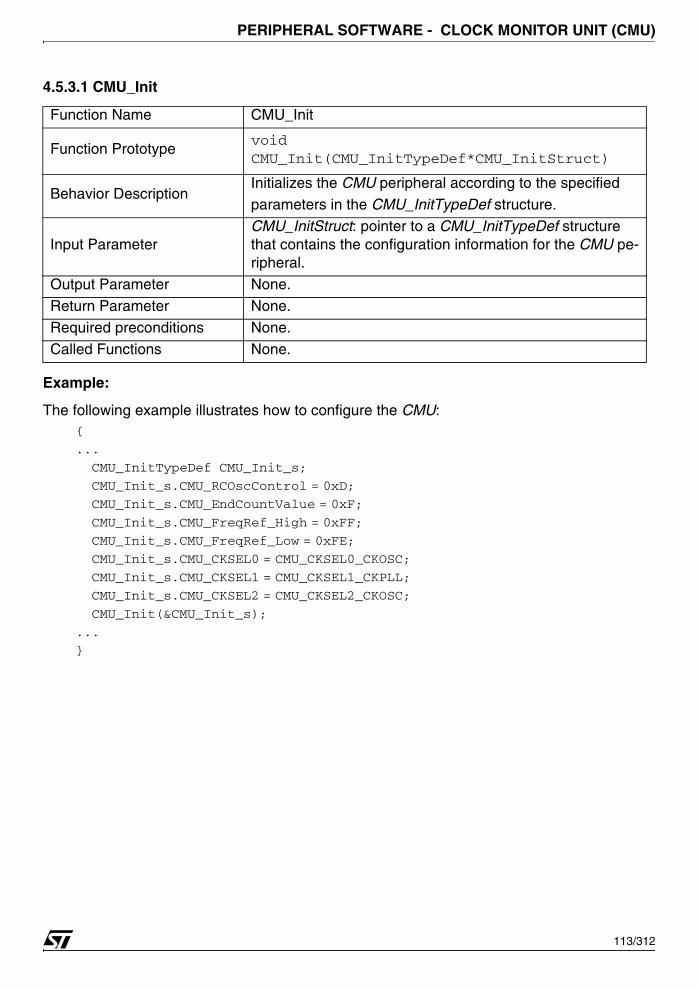
PERIPHERAL SOFTWARE - CLOCK MONITOR UNIT (CMU)
4.5.3.1 CMU_Init
Example:
The following example illustrates how to configure the CMU:{
...
CMU_InitTypeDef CMU_Init_s;
CMU_Init_s.CMU_RCOscControl = 0xD;
CMU_Init_s.CMU_EndCountValue = 0xF;
CMU_Init_s.CMU_FreqRef_High = 0xFF;
CMU_Init_s.CMU_FreqRef_Low = 0xFE;
CMU_Init_s.CMU_CKSEL0 = CMU_CKSEL0_CKOSC;
CMU_Init_s.CMU_CKSEL1 = CMU_CKSEL1_CKPLL;
CMU_Init_s.CMU_CKSEL2 = CMU_CKSEL2_CKOSC;
CMU_Init(&CMU_Init_s);
...
}
Function Name CMU_Init
Function Prototypevoid CMU_Init(CMU_InitTypeDef*CMU_InitStruct)
Behavior DescriptionInitializes the CMU peripheral according to the specified
parameters in the CMU_InitTypeDef structure.
Input Parameter CMU_InitStruct: pointer to a CMU_InitTypeDef structure that contains the configuration information for the CMU pe-ripheral.
Output Parameter None.
Return Parameter None.
Required preconditions None.
Called Functions None.
113/312

PERIPHERAL SOFTWARE - CLOCK MONITOR UNIT (CMU)
4.5.3.2 CMU_DeInit
Example:
The following example illustrates how to deinitialize the CMU peripheral:{
...
CMU_DeInit();
...
}
4.5.3.3 CMU_StructInit
Example:
The following example illustrates how to initialize the CMU structure:{
CMU_StructInit (&CMU_InitStruct);
...
}
Function Name CMU_DeInit
Function Prototype void CMU_DeInit(void)
Behavior DescriptionDeinitializes the CMU peripheral registers to their default re-set values.
Input Parameter None.
Output Parameter None
Return Parameter None
Required preconditions NoneCalled Functions None
Function Name CMU_StructInit
Function Prototypevoid CMU_StructInit(CMU_InitTypeDef* CMU_InitStruct)
Behavior DescriptionFills in a CMU_InitTypeDef structure with the reset value of each parameter.
Input ParameterCMU_InitStruct: pointer to a CMU_InitTypeDef structure which will be initialized.
Output Parameter None
Return Parameter None
Required preconditions NoneCalled Functions None
114/312
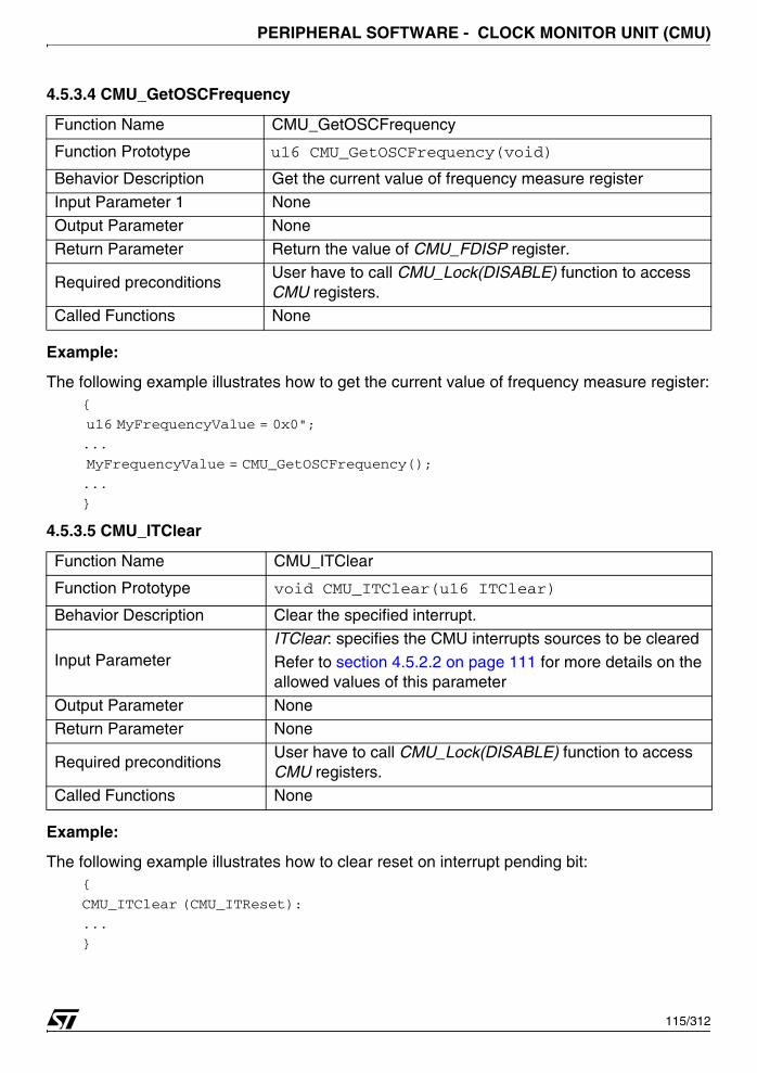
PERIPHERAL SOFTWARE - CLOCK MONITOR UNIT (CMU)
4.5.3.4 CMU_GetOSCFrequency
Example:
The following example illustrates how to get the current value of frequency measure register:{
u16 MyFrequencyValue = 0x0";
...
MyFrequencyValue = CMU_GetOSCFrequency();
...
}
4.5.3.5 CMU_ITClear
Example:
The following example illustrates how to clear reset on interrupt pending bit:{
CMU_ITClear (CMU_ITReset):
...
}
Function Name CMU_GetOSCFrequency
Function Prototype u16 CMU_GetOSCFrequency(void)
Behavior Description Get the current value of frequency measure register
Input Parameter 1 None
Output Parameter None
Return Parameter Return the value of CMU_FDISP register.
Required preconditionsUser have to call CMU_Lock(DISABLE) function to access CMU registers.
Called Functions None
Function Name CMU_ITClear
Function Prototype void CMU_ITClear(u16 ITClear)
Behavior Description Clear the specified interrupt.
Input ParameterITClear: specifies the CMU interrupts sources to be cleared
Refer to section 4.5.2.2 on page 111 for more details on the allowed values of this parameter
Output Parameter NoneReturn Parameter None
Required preconditionsUser have to call CMU_Lock(DISABLE) function to access CMU registers.
Called Functions None
115/312

PERIPHERAL SOFTWARE - CLOCK MONITOR UNIT (CMU)
4.5.3.6 CMU_FlagClear
Example:
The following example illustrates how to clear CRF flag:{
...
CMU_FlagClear( );
...
}
4.5.3.7 CMU_Lock
Example:
The following example illustrates how to enable write access to all CMU registers: {
...
CMU_Lock(DISABLE);
...
}
Function Name CMU_FlagClear
Function Prototype void CMU_FlagClear(void)
Behavior Description Clear the CRF flag in status register.
Input Parameter None.
Output Parameter None
Return Parameter None
Required preconditionsUser have to call CMU_Lock(DISABLE) function to access CMU registers.
Called Functions None
Function Name CMU_Lock
Function Prototype void CMU_Lock (FunctionalState NewState)
Behavior Description Enable or disable access to all CMU register.
Input Parameter NewState: new state of the CMU peripheral. This parametercan be: ENABLE or DISABLE
Output Parameter None
Return Parameter None
Required preconditions None
Called Functions None
116/312

PERIPHERAL SOFTWARE - CLOCK MONITOR UNIT (CMU)
4.5.3.8 CMU_StopOscConfig
Example:
The following example illustrates how to stop main oscillator:{
CMU_StopOscConfig (CMU_MainoscStop);
...
}
4.5.3.9 CMU_FlagStatus
Example:
The following example illustrates how to test if the CKOSC drives the digital logic:{
FlagStatus Status;
...
Status = CMU_FlagStatus(CMU_CKON0bit);
...
}
Function Name CMU_StopOscConfig
Function Prototype void CMU_StopOscConfig (u16 CMU_StopOsc)
Behavior Description Stop the specified source of oscillator clock.
Input ParameterCMU_StopOsc: Source of clock will be stopped.Refer to the section ‘CMU Stop oscillator’ for more details on the allowed values of this parameter
Output Parameter None
Return Parameter None
Required preconditionsCMU_Lock(..) function has to be used before calling this function.
Called Functions None
Function Name CMU_FlagStatus
Function Prototype FlagStatus CMU_FlagStatus (u8 CMU_Flag)
Description Checks whether the specified CMU flag is set or not.
Input ParameterCMU_Flag: flag to check.
Refer to section 4.2.3.17 on page 67 for more details on the allowed values of this parameter
OutPut Parameter None
Return Parameters The NewState of the CMU_Flag (SET or RESET).
Required Preconditions NoneCalled Functions None
117/312

PERIPHERAL SOFTWARE - CLOCK MONITOR UNIT (CMU)
4.5.3.10 CMU_ITConfig
Example:
The following example illustrates how to enable the end of counter interrupt:{
CMU_ITConfig (CMU_ITEndCounter, ENABLE );
}
4.5.3.11 CMU_ResetConfig
Example:
The following example illustrates how to enable the reset generation of the CMU:{
CMU_ResetConfig (ENABLE);
}
Function Name CMU_ITConfig
Function Prototypevoid CMU_ITConfig (u8 CMU_IT, FunctionalState NewState)
Behavior Description Enables or disables the specified CMU interrupts.
Input Parameter 1CMU_IT: specifies the CMU interrupts sources to be ena-bled or disabled. Refer to section 4.5.2.2 on page 111 for more details on the allowed values of this parameter
Input Parameter 2NewState: new state of the specified CMU interrupts This parameter can be: ENABLE or DISABLE.
Output Parameter None
Return Parameter None
Required preconditionsCMU_Lock(..) function has to be used before calling this function.
Called Functions None
Function Name CMU_ResetConfig
Function Prototypevoid CMU_ResetConfig (FunctionalState NewState)
Behavior Description Enable or disable Reset generation.
Input ParameterNewState: new state of the CMU peripheral. This parameter can be: ENABLE or DISABLE.
Output Parameter None
Return Parameter None
Required preconditionsCMU_Lock(..) function has to be used before calling this function.
Called Functions None
118/312
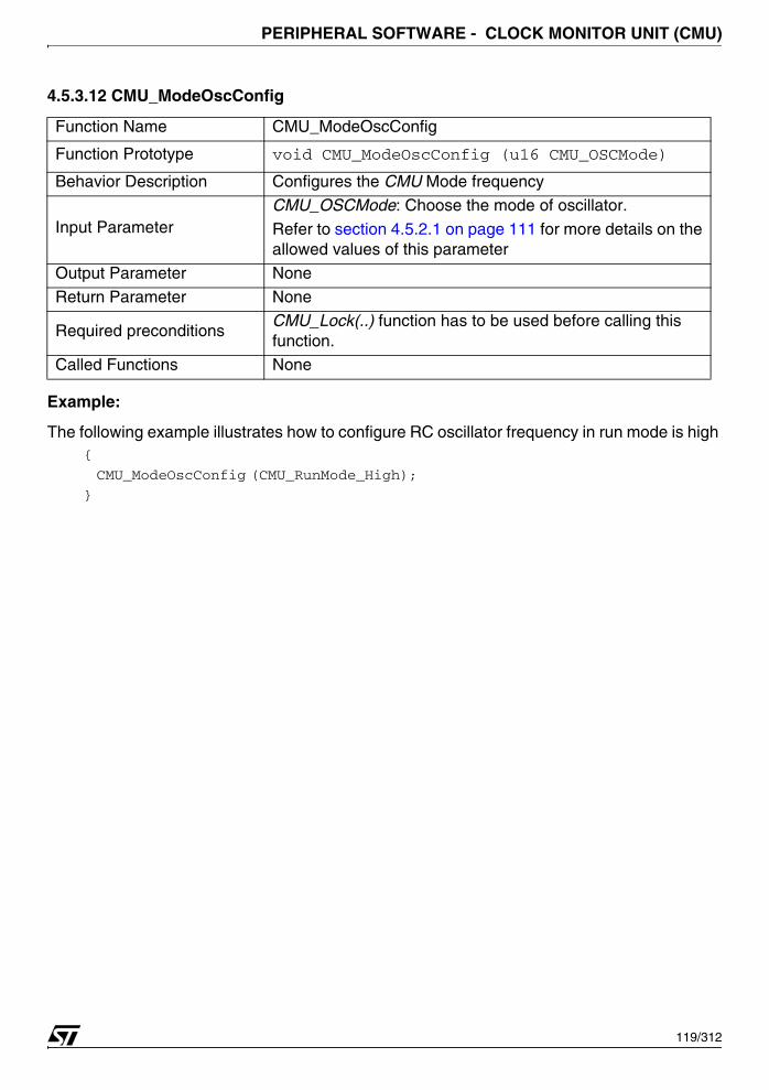
PERIPHERAL SOFTWARE - CLOCK MONITOR UNIT (CMU)
4.5.3.12 CMU_ModeOscConfig
Example:
The following example illustrates how to configure RC oscillator frequency in run mode is high {
CMU_ModeOscConfig (CMU_RunMode_High);
}
Function Name CMU_ModeOscConfig
Function Prototype void CMU_ModeOscConfig (u16 CMU_OSCMode)
Behavior Description Configures the CMU Mode frequency
Input Parameter CMU_OSCMode: Choose the mode of oscillator.
Refer to section 4.5.2.1 on page 111 for more details on the allowed values of this parameter
Output Parameter None
Return Parameter None
Required preconditionsCMU_Lock(..) function has to be used before calling this function.
Called Functions None
119/312
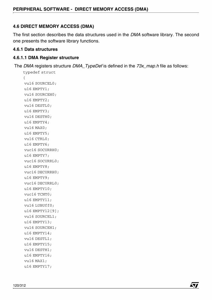
PERIPHERAL SOFTWARE - DIRECT MEMORY ACCESS (DMA)
4.6 DIRECT MEMORY ACCESS (DMA)
The first section describes the data structures used in the DMA software library. The secondone presents the software library functions.
4.6.1 Data structures
4.6.1.1 DMA Register structure
The DMA registers structure DMA_TypeDef is defined in the 73x_map.h file as follows:typedef struct
{
vu16 SOURCEL0;
u16 EMPTY1;
vu16 SOURCEH0;
u16 EMPTY2;
vu16 DESTL0;
u16 EMPTY3;
vu16 DESTH0;
u16 EMPTY4;
vu16 MAX0;
u16 EMPTY5;
vu16 CTRL0;
u16 EMPTY6;
vuc16 SOCURRH0;
u16 EMPTY7;
vuc16 SOCURRL0;
u16 EMPTY8;
vuc16 DECURRH0;
u16 EMPTY9;
vuc16 DECURRL0;
u16 EMPTY10;
vuc16 TCNT0;
u16 EMPTY11;
vu16 LUBUff0;
u16 EMPTY12[9];
vu16 SOURCEL1;
u16 EMPTY13;
vu16 SOURCEH1;
u16 EMPTY14;
vu16 DESTL1;
u16 EMPTY15;
vu16 DESTH1;
u16 EMPTY16;
vu16 MAX1;
u16 EMPTY17;
120/312

PERIPHERAL SOFTWARE - DIRECT MEMORY ACCESS (DMA)
vu16 CTRL1;
u16 EMPTY18;
vuc16 SOCURRH1;
u16 EMPTY19;
vuc16 SOCURRL1;
u16 EMPTY20;
vuc16 DECURRH1;
u16 EMPTY21;
vuc16 DECURRL1;
u16 EMPTY22;
vuc16 TCNT1;
u16 EMPTY23;
vu16 LUBUff1;
u16 EMPTY24[9];
vu16 SOURCEL2;
u16 EMPTY25;
vu16 SOURCEH2;
u16 EMPTY26;
vu16 DESTL2;
u16 EMPTY27;
vu16 DESTH2;
u16 EMPTY28;
vu16 MAX2;
u16 EMPTY29;
vu16 CTRL2;
u16 EMPTY30;
vuc16 SOCURRH2;
u16 EMPTY31;
vuc16 SOCURRL2;
u16 EMPTY32;
vuc16 DESCURRH2;
u16 EMPTY33;
vuc16 DESCURRL2;
u16 EMPTY34;
vuc16 TCNT2;
u16 EMPTY35;
vu16 LUBUff2;
u16 EMPTY36[9];
vu16 SOURCEL3;
u16 EMPTY37;
vu16 SOURCEH3;
u16 EMPTY38;
vu16 DESTL3;
u16 EMPTY39;
vu16 DESTH3;
121/312

PERIPHERAL SOFTWARE - DIRECT MEMORY ACCESS (DMA)
u16 EMPTY40;
vu16 MAX3;
u16 EMPTY41;
vu16 CTRL3;
u16 EMPTY42;
vuc16 SOCURRH3;
u16 EMPTY43;
vuc16 SOCURRL3;
u16 EMPTY44;
vuc16 DECURRH3;
u16 EMPTY45;
vuc16 DECURRL3;
u16 EMPTY46;
vuc16 TCNT3;
u16 EMPTY47;
vu16 LUBUff3;
u16 EMPTY48;
vu16 MASK;
u16 EMPTY49;
vu16 CLR;
u16 EMPTY50;
vu16 STATUS;
u16 EMPTY51;
vu16 Last;
u16 EMPTY52;
} DMA_TypeDef;
The following table presents the DMA registers:
Register DescriptionSOURCELx DMA Streamx Source Base Address Low
SOURCEHx DMA Streamx Source Base Address HighDESTLx DMA Streamx Destination Base Address Low
DESTHx DMA Streamx Destination Base Address High
MAXx DMA Streamx Maximum Count Register
CTRLx DMA Streamx Control Register
SOCURRHx DMA Streamx Current Source Address High
SOCURRLx DMA Streamx Current Source Address LowDECURRHx DMA Streamx Current Destination Address High
DECURRLx DMA Streamx Current Destination Address Low
TCNTx DMA Streamx Terminal Counter Register
122/312

PERIPHERAL SOFTWARE - DIRECT MEMORY ACCESS (DMA)
The four DMA controllers are declared in the same file:...
#define APB_BASE 0xFFFF8000
....
#define DMA0_BASE (APB + 0x7000)
#define DMA1_BASE (APB + 0x7100)
#define DMA2_BASE (APB + 0x7200)
#define DMA3_BASE (APB + 0x7300)
#ifndef DEBUG
...
#define DMA0 ((DMA_TypeDef *) DMA0_BASE)
#define DMA1 ((DMA_TypeDef *) DMA1_BASE)
#define DMA2 ((DMA_TypeDef *) DMA2_BASE)
#define DMA3 ((DMA_TypeDef *) DMA3_BASE)
...
#else
...
EXT DMA_TypeDef *DMA0;
EXT DMA_TypeDef *DMA1;
EXT DMA_TypeDef *DMA2;
EXT DMA_TypeDef *DMA3;
...
#endif
When debug mode is used, DMA pointer is initialized in 73x_lib.c file:#ifdef _DMA0
DMA0 = (DMA_TypeDef *)DMA0_BASE;
#endif /*_DMA0 */
#ifdef _DMA1
DMA1 = (DMA_TypeDef *)DMA1_BASE;
#endif /*_DMA1 */
#ifdef _DMA2
DMA2 = (DMA_TypeDef *)DMA2_BASE;
#endif /*_DMA2 */
LUBUffx DMA Streamx Last Used Buffer locationMASK DMA Interrupt Mask Register
CLR DMA Interrupt Clear Register
STATUS DMA Interrupt Status Register
Last DMA Last Flag Register
Register Description
123/312
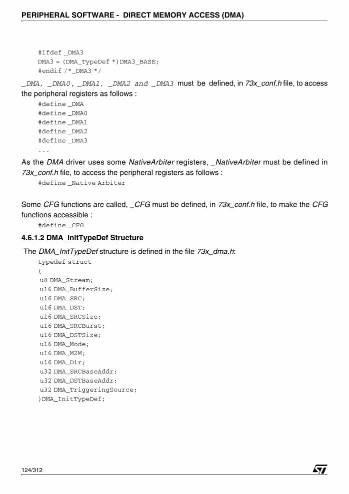
PERIPHERAL SOFTWARE - DIRECT MEMORY ACCESS (DMA)
#ifdef _DMA3
DMA3 = (DMA_TypeDef *)DMA3_BASE;
#endif /*_DMA3 */
_DMA, _DMA0 , _DMA1, _DMA2 and _DMA3 must be defined, in 73x_conf.h file, to accessthe peripheral registers as follows :
#define _DMA
#define _DMA0
#define _DMA1
#define _DMA2
#define _DMA3
...
As the DMA driver uses some NativeArbiter registers, _NativeArbiter must be defined in73x_conf.h file, to access the peripheral registers as follows :
#define _Native Arbiter
Some CFG functions are called, _CFG must be defined, in 73x_conf.h file, to make the CFGfunctions accessible :
#define _CFG
4.6.1.2 DMA_InitTypeDef Structure
The DMA_InitTypeDef structure is defined in the file 73x_dma.h:typedef struct
{
u8 DMA_Stream;
u16 DMA_BufferSize;
u16 DMA_SRC;
u16 DMA_DST;
u16 DMA_SRCSize;
u16 DMA_SRCBurst;
u16 DMA_DSTSize;
u16 DMA_Mode;
u16 DMA_M2M;
u16 DMA_Dir;
u32 DMA_SRCBaseAddr;
u32 DMA_DSTBaseAddr;
u32 DMA_TriggeringSource;
}DMA_InitTypeDef;
124/312

PERIPHERAL SOFTWARE - DIRECT MEMORY ACCESS (DMA)
Members■ DMA_Stream
Specifies the DMA stream to be used.
This member can be one of the following values.
■ DMA_BufferSize
Specifies the buffer size, in data unit, of the specified stream.
The data unit is equal to the configuration set in DMA_SRCSize member.
■ DMA_SRC
Specifies whether the current source register is incremented.
This member can be one of the following values.
■ DMA_DST
Specifies whether the current destination register is incremented.
This member can be one of the following values
■ DMA_SRCSize
Specifies the data width for source to DMA stream data transfer.
This member can be one of the following values.
DMA_Stream MeaningDMA_Stream0 Uses Stream0
DMA_Stream1 Uses Stream1
DMA_Stream2 Uses Stream2 DMA_Stream3 Uses Stream3
DMA_SRC MeaningDMA_SRC_INCR Current source register incremented
DMA_SRC_NOT_INCR Current source register unchanged
DMA_DST MeaningDMA_DST_INCR Current destination register incremented
DMA_DST_NOT_INCR Current destination register unchanged
DMA_SRCSize MeaningDMA_SRCSize_Byte Data width is 8 bits
DMA_SRCSize_HalfWord Data width is 16 bits
DMA_SRCSize_Word Data width is 32 bits
125/312
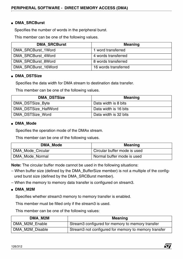
PERIPHERAL SOFTWARE - DIRECT MEMORY ACCESS (DMA)
■ DMA_SRCBurst
Specifies the number of words in the peripheral burst.
This member can be one of the following values.
■ DMA_DSTSize
Specifies the data width for DMA stream to destination data transfer.
This member can be one of the following values.
■ DMA_Mode
Specifies the operation mode of the DMAx stream.
This member can be one of the following values.
Note: The circular buffer mode cannot be used in the following situations:
– When buffer size (defined by the DMA_BufferSize member) is not a multiple of the config-ured burst size (defined by the DMA_SRCBurst member).
– When the memory to memory data transfer is configured on stream3.
■ DMA_M2M
Specifies whether stream3 memory to memory transfer is enabled.
This member must be filled only if the stream3 is used.
This member can be one of the following values:
DMA_SRCBurst MeaningDMA_SRCBurst_1Word 1 word transferred
DMA_SRCBurst_4Word 4 words transferred
DMA_SRCBurst_8Word 8 words transferred
DMA_SRCBurst_16Word 16 words transferred
DMA_DSTSize MeaningDMA_DSTSize_Byte Data width is 8 bits
DMA_DSTSize_HalfWord Data width is 16 bits
DMA_DSTSize_Word Data width is 32 bits
DMA_Mode MeaningDMA_Mode_Circular Circular buffer mode is used
DMA_Mode_Normal Normal buffer mode is used
DMA_M2M MeaningDMA_M2M_Enable Stream3 configured for memory to memory transfer
DMA_M2M_Disable Stream3 not configured for memory to memory transfer
126/312

PERIPHERAL SOFTWARE - DIRECT MEMORY ACCESS (DMA)
■ DMA_Dir
Specifies if the peripheral is the source or the destination.
This member can be one of the following values:
■ DMA_SRCBaseAddr
Specifies the base address for streamx source DMA buffer.
■ DMA_DSTBaseAddr
Specifies the base address for streamx destination DMA buffer.
■ DMA_TriggeringSource
Specifies the triggering source for DMA0 Stream2 and DMA0 Stream3, DMA2 Stream3
and DMA3 Stream2. This member must be filled only if the stream to be used is one
from those described above.
This member can be one of the following values:.
4.6.2 Common Parameter Values
4.6.2.1 DMA priority
The DMA priorities, defined in 73x_dma.h, are listed below:
DMA_Dir MeaningDMA_Dir_PeriphDST Peripheral is the destination
DMA_Dir_PeriphSRC Peripheral is the source
DMA_TriggeringSource Meaning
DMA_TriggeringSource_BSPI0 BSPI0 is the triggering source for both DMA0 Stream2 and DMA0 Stream3
DMA_TriggeringSource_BSPI1BSPI1 is the triggering source for both DMA2 Stream3 and DMA3 Stream2
DMA_TriggeringSource_TIM8_TIM9TIM8 is the triggering source for DMA2 Stream3 and TIM9 is the triggering source for DMA3 Stream2
DMA_Priority MeaningDMA_Priority_High DMA has the highest priority on AHB bus.DMA_Priority_Low CPU has the highest priority on AHB bus.
127/312
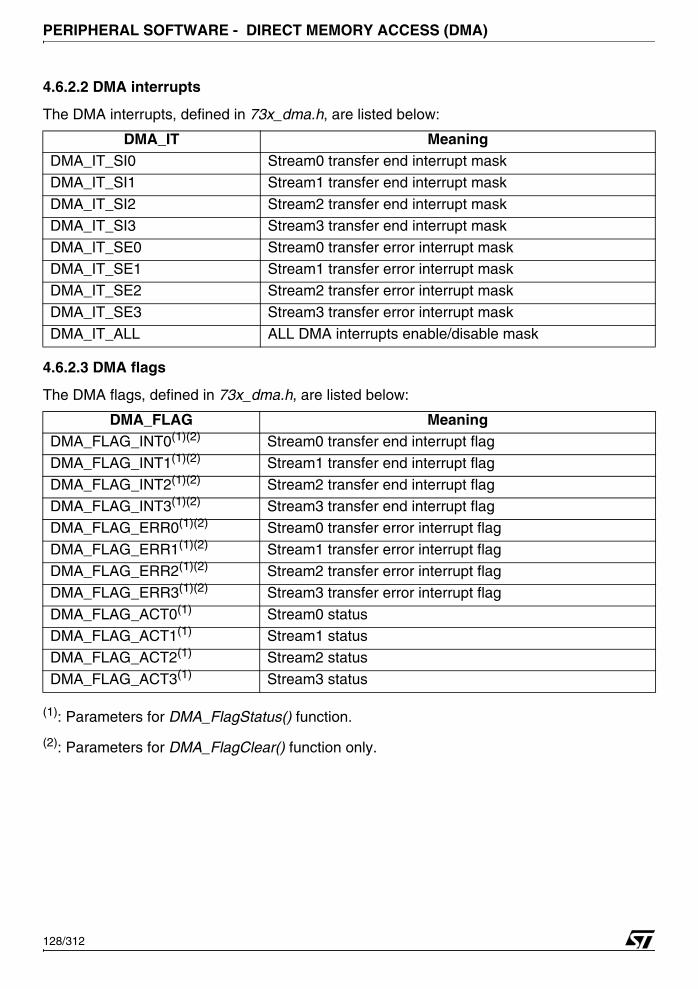
PERIPHERAL SOFTWARE - DIRECT MEMORY ACCESS (DMA)
4.6.2.2 DMA interrupts
The DMA interrupts, defined in 73x_dma.h, are listed below:
4.6.2.3 DMA flags
The DMA flags, defined in 73x_dma.h, are listed below:
(1): Parameters for DMA_FlagStatus() function.
(2): Parameters for DMA_FlagClear() function only.
DMA_IT MeaningDMA_IT_SI0 Stream0 transfer end interrupt mask
DMA_IT_SI1 Stream1 transfer end interrupt mask
DMA_IT_SI2 Stream2 transfer end interrupt mask
DMA_IT_SI3 Stream3 transfer end interrupt mask
DMA_IT_SE0 Stream0 transfer error interrupt maskDMA_IT_SE1 Stream1 transfer error interrupt mask
DMA_IT_SE2 Stream2 transfer error interrupt mask
DMA_IT_SE3 Stream3 transfer error interrupt mask
DMA_IT_ALL ALL DMA interrupts enable/disable mask
DMA_FLAG MeaningDMA_FLAG_INT0(1)(2) Stream0 transfer end interrupt flag
DMA_FLAG_INT1(1)(2) Stream1 transfer end interrupt flag
DMA_FLAG_INT2(1)(2) Stream2 transfer end interrupt flagDMA_FLAG_INT3(1)(2) Stream3 transfer end interrupt flag
DMA_FLAG_ERR0(1)(2) Stream0 transfer error interrupt flag
DMA_FLAG_ERR1(1)(2) Stream1 transfer error interrupt flag
DMA_FLAG_ERR2(1)(2) Stream2 transfer error interrupt flag
DMA_FLAG_ERR3(1)(2) Stream3 transfer error interrupt flag
DMA_FLAG_ACT0(1) Stream0 statusDMA_FLAG_ACT1(1) Stream1 status
DMA_FLAG_ACT2(1) Stream2 status
DMA_FLAG_ACT3(1) Stream3 status
128/312
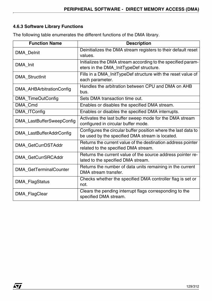
PERIPHERAL SOFTWARE - DIRECT MEMORY ACCESS (DMA)
4.6.3 Software Library Functions
The following table enumerates the different functions of the DMA library.
Function Name Description
DMA_DeInitDeinitializes the DMA stream registers to their default reset values.
DMA_InitInitializes the DMA stream according to the specified param-eters in the DMA_InitTypeDef structure.
DMA_StructInitFills in a DMA_InitTypeDef structure with the reset value of each parameter.
DMA_AHBArbitrationConfigHandles the arbitration between CPU and DMA on AHB bus.
DMA_TimeOutConfig Sets DMA transaction time out.
DMA_Cmd Enables or disables the specified DMA stream.DMA_ITConfig Enables or disables the specified DMA interrupts.
DMA_LastBufferSweepConfigActivates the last buffer sweep mode for the DMA stream configured in circular buffer mode.
DMA_LastBufferAddrConfigConfigures the circular buffer position where the last data to be used by the specified DMA stream is located.
DMA_GetCurrDSTAddrReturns the current value of the destination address pointer related to the specified DMA stream.
DMA_GetCurrSRCAddrReturns the current value of the source address pointer re-lated to the specified DMA stream.
DMA_GetTerminalCounterReturns the number of data units remaining in the current DMA stream transfer.
DMA_FlagStatusChecks whether the specified DMA controller flag is set or not.
DMA_FlagClearClears the pending interrupt flags corresponding to the specified DMA stream.
129/312
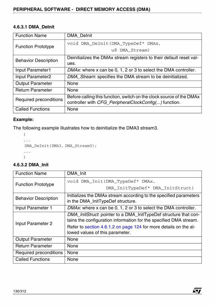
PERIPHERAL SOFTWARE - DIRECT MEMORY ACCESS (DMA)
4.6.3.1 DMA_DeInit
Example:
The following example illustrates how to deinitialize the DMA3 stream3.{
...
DMA_DeInit(DMA3, DMA_Stream3);
...
}
4.6.3.2 DMA_Init
Function Name DMA_DeInit
Function Prototypevoid DMA_DeInit(DMA_TypeDef* DMAx,
u8 DMA_Stream)
Behavior DescriptionDeinitializes the DMAx stream registers to their default reset val-ues.
Input Parameter1 DMAx: where x can be 0, 1, 2 or 3 to select the DMA controller.
Input Parameter2 DMA_Stream: specifies the DMA stream to be deinitialized.
Output Parameter NoneReturn Parameter None
Required preconditionsBefore calling this function, switch on the clock source of the DMAx controller with CFG_PeripheralClockConfig(...) function.
Called Functions None
Function Name DMA_Init
Function Prototypevoid DMA_Init(DMA_TypeDef* DMAx,
DMA_InitTypeDef* DMA_InitStruct)
Behavior DescriptionInitializes the DMAx stream according to the specified parameters in the DMA_InitTypeDef structure.
Input Parameter 1 DMAx: where x can be 0, 1, 2 or 3 to select the DMA controller.
Input Parameter 2
DMA_InitStruct: pointer to a DMA_InitTypeDef structure that con-tains the configuration information for the specified DMA stream.
Refer to section 4.6.1.2 on page 124 for more details on the al-lowed values of this parameter.
Output Parameter None
Return Parameter None
Required preconditions None
Called Functions None
130/312
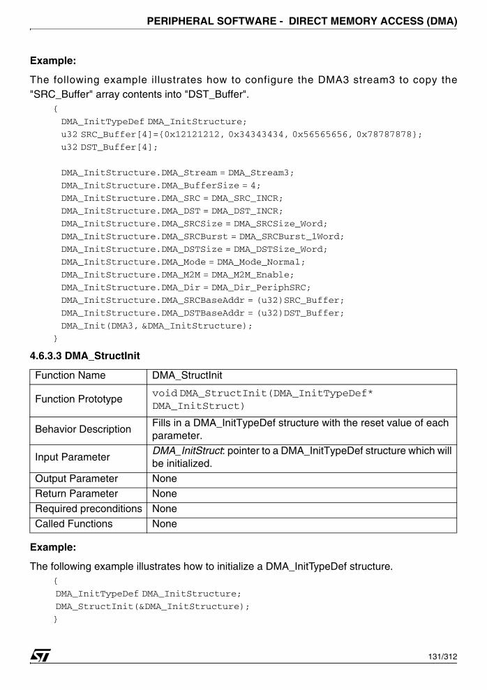
PERIPHERAL SOFTWARE - DIRECT MEMORY ACCESS (DMA)
Example:
The following example illustrates how to configure the DMA3 stream3 to copy the"SRC_Buffer" array contents into "DST_Buffer".
{
DMA_InitTypeDef DMA_InitStructure;
u32 SRC_Buffer[4]={0x12121212, 0x34343434, 0x56565656, 0x78787878};
u32 DST_Buffer[4];
DMA_InitStructure.DMA_Stream = DMA_Stream3;
DMA_InitStructure.DMA_BufferSize = 4;
DMA_InitStructure.DMA_SRC = DMA_SRC_INCR;
DMA_InitStructure.DMA_DST = DMA_DST_INCR;
DMA_InitStructure.DMA_SRCSize = DMA_SRCSize_Word;
DMA_InitStructure.DMA_SRCBurst = DMA_SRCBurst_1Word;
DMA_InitStructure.DMA_DSTSize = DMA_DSTSize_Word;
DMA_InitStructure.DMA_Mode = DMA_Mode_Normal;
DMA_InitStructure.DMA_M2M = DMA_M2M_Enable;
DMA_InitStructure.DMA_Dir = DMA_Dir_PeriphSRC;
DMA_InitStructure.DMA_SRCBaseAddr = (u32)SRC_Buffer;
DMA_InitStructure.DMA_DSTBaseAddr = (u32)DST_Buffer;
DMA_Init(DMA3, &DMA_InitStructure);
}
4.6.3.3 DMA_StructInit
Example:
The following example illustrates how to initialize a DMA_InitTypeDef structure.{
DMA_InitTypeDef DMA_InitStructure;
DMA_StructInit(&DMA_InitStructure);
}
Function Name DMA_StructInit
Function Prototypevoid DMA_StructInit(DMA_InitTypeDef* DMA_InitStruct)
Behavior DescriptionFills in a DMA_InitTypeDef structure with the reset value of each parameter.
Input Parameter DMA_InitStruct: pointer to a DMA_InitTypeDef structure which will be initialized.
Output Parameter NoneReturn Parameter None
Required preconditions None
Called Functions None
131/312
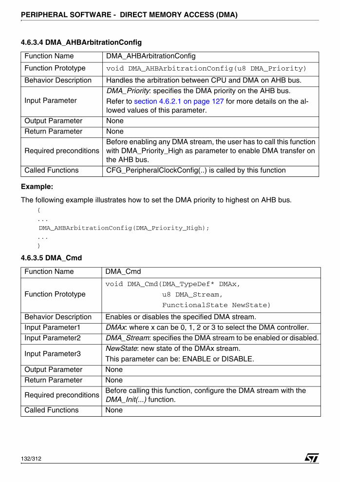
PERIPHERAL SOFTWARE - DIRECT MEMORY ACCESS (DMA)
4.6.3.4 DMA_AHBArbitrationConfig
Example:
The following example illustrates how to set the DMA priority to highest on AHB bus.{
...
DMA_AHBArbitrationConfig(DMA_Priority_High);
...
}
4.6.3.5 DMA_Cmd
Function Name DMA_AHBArbitrationConfig
Function Prototype void DMA_AHBArbitrationConfig(u8 DMA_Priority)
Behavior Description Handles the arbitration between CPU and DMA on AHB bus.
Input Parameter DMA_Priority: specifies the DMA priority on the AHB bus.
Refer to section 4.6.2.1 on page 127 for more details on the al-lowed values of this parameter.
Output Parameter None
Return Parameter None
Required preconditionsBefore enabling any DMA stream, the user has to call this function with DMA_Priority_High as parameter to enable DMA transfer on the AHB bus.
Called Functions CFG_PeripheralClockConfig(..) is called by this function
Function Name DMA_Cmd
Function Prototype
void DMA_Cmd(DMA_TypeDef* DMAx,
u8 DMA_Stream,
FunctionalState NewState)
Behavior Description Enables or disables the specified DMA stream.Input Parameter1 DMAx: where x can be 0, 1, 2 or 3 to select the DMA controller.
Input Parameter2 DMA_Stream: specifies the DMA stream to be enabled or disabled.
Input Parameter3NewState: new state of the DMAx stream.
This parameter can be: ENABLE or DISABLE.
Output Parameter None
Return Parameter None
Required preconditionsBefore calling this function, configure the DMA stream with the DMA_Init(...) function.
Called Functions None
132/312
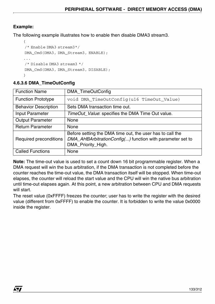
PERIPHERAL SOFTWARE - DIRECT MEMORY ACCESS (DMA)
Example:
The following example illustrates how to enable then disable DMA3 stream3.{
/* Enable DMA3 stream3*/
DMA_Cmd(DMA3, DMA_Stream3, ENABLE);
...
/* Disable DMA3 stream3 */
DMA_Cmd(DMA3, DMA_Stream3, DISABLE);
}
4.6.3.6 DMA_TimeOutConfig
Note: The time-out value is used to set a count down 16 bit programmable register. When a DMA request will win the bus arbitration, if the DMA transaction is not completed before the counter reaches the time-out value, the DMA transaction itself will be stopped. When time-out elapses, the counter will reload the start value and the CPU will win the native bus arbitration until time-out elapses again. At this point, a new arbitration between CPU and DMA requests will start.The reset value (0xFFFF) freezes the counter; user has to write the register with the desired value (different from 0xFFFF) to enable the counter. It is forbidden to write the value 0x0000 inside the register.
Function Name DMA_TimeOutConfig
Function Prototype void DMA_TimeOutConfig(u16 TimeOut_Value)
Behavior Description Sets DMA transaction time out.
Input Parameter TimeOut_Value: specifies the DMA Time Out value.Output Parameter None
Return Parameter None
Required preconditionsBefore setting the DMA time out, the user has to call the DMA_AHBArbitrationConfig(...) function with parameter set to DMA_Priority_High.
Called Functions None
133/312
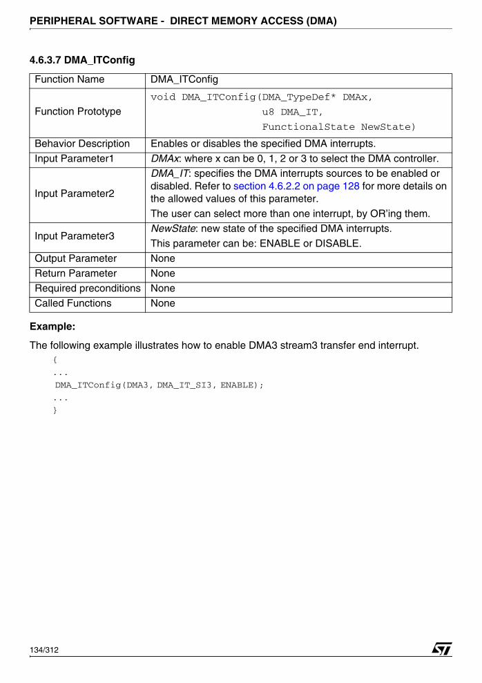
PERIPHERAL SOFTWARE - DIRECT MEMORY ACCESS (DMA)
4.6.3.7 DMA_ITConfig
Example:
The following example illustrates how to enable DMA3 stream3 transfer end interrupt.{
...
DMA_ITConfig(DMA3, DMA_IT_SI3, ENABLE);
...
}
Function Name DMA_ITConfig
Function Prototype
void DMA_ITConfig(DMA_TypeDef* DMAx,
u8 DMA_IT,
FunctionalState NewState)
Behavior Description Enables or disables the specified DMA interrupts.
Input Parameter1 DMAx: where x can be 0, 1, 2 or 3 to select the DMA controller.
Input Parameter2
DMA_IT: specifies the DMA interrupts sources to be enabled or disabled. Refer to section 4.6.2.2 on page 128 for more details on the allowed values of this parameter.
The user can select more than one interrupt, by OR’ing them.
Input Parameter3NewState: new state of the specified DMA interrupts.
This parameter can be: ENABLE or DISABLE.
Output Parameter None
Return Parameter None
Required preconditions None
Called Functions None
134/312
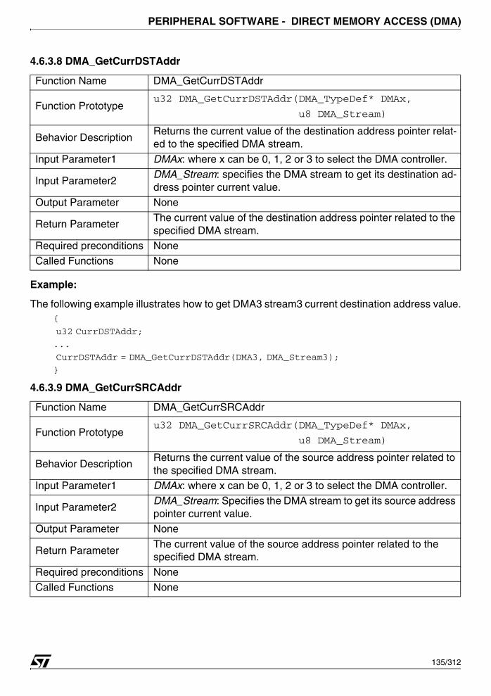
PERIPHERAL SOFTWARE - DIRECT MEMORY ACCESS (DMA)
4.6.3.8 DMA_GetCurrDSTAddr
Example:
The following example illustrates how to get DMA3 stream3 current destination address value.{
u32 CurrDSTAddr;
...
CurrDSTAddr = DMA_GetCurrDSTAddr(DMA3, DMA_Stream3);
}
4.6.3.9 DMA_GetCurrSRCAddr
Function Name DMA_GetCurrDSTAddr
Function Prototypeu32 DMA_GetCurrDSTAddr(DMA_TypeDef* DMAx,
u8 DMA_Stream)
Behavior DescriptionReturns the current value of the destination address pointer relat-ed to the specified DMA stream.
Input Parameter1 DMAx: where x can be 0, 1, 2 or 3 to select the DMA controller.
Input Parameter2 DMA_Stream: specifies the DMA stream to get its destination ad-dress pointer current value.
Output Parameter None
Return ParameterThe current value of the destination address pointer related to the specified DMA stream.
Required preconditions NoneCalled Functions None
Function Name DMA_GetCurrSRCAddr
Function Prototypeu32 DMA_GetCurrSRCAddr(DMA_TypeDef* DMAx,
u8 DMA_Stream)
Behavior DescriptionReturns the current value of the source address pointer related to the specified DMA stream.
Input Parameter1 DMAx: where x can be 0, 1, 2 or 3 to select the DMA controller.
Input Parameter2 DMA_Stream: Specifies the DMA stream to get its source address pointer current value.
Output Parameter None
Return ParameterThe current value of the source address pointer related to the specified DMA stream.
Required preconditions None
Called Functions None
135/312
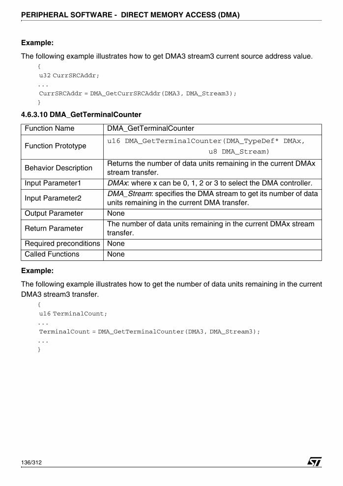
PERIPHERAL SOFTWARE - DIRECT MEMORY ACCESS (DMA)
Example:
The following example illustrates how to get DMA3 stream3 current source address value.{
u32 CurrSRCAddr;
...
CurrSRCAddr = DMA_GetCurrSRCAddr(DMA3, DMA_Stream3);
}
4.6.3.10 DMA_GetTerminalCounter
Example:
The following example illustrates how to get the number of data units remaining in the currentDMA3 stream3 transfer.
{
u16 TerminalCount;
...
TerminalCount = DMA_GetTerminalCounter(DMA3, DMA_Stream3);
...
}
Function Name DMA_GetTerminalCounter
Function Prototypeu16 DMA_GetTerminalCounter(DMA_TypeDef* DMAx,
u8 DMA_Stream)
Behavior DescriptionReturns the number of data units remaining in the current DMAx stream transfer.
Input Parameter1 DMAx: where x can be 0, 1, 2 or 3 to select the DMA controller.
Input Parameter2 DMA_Stream: specifies the DMA stream to get its number of data units remaining in the current DMA transfer.
Output Parameter None
Return ParameterThe number of data units remaining in the current DMAx stream transfer.
Required preconditions None
Called Functions None
136/312
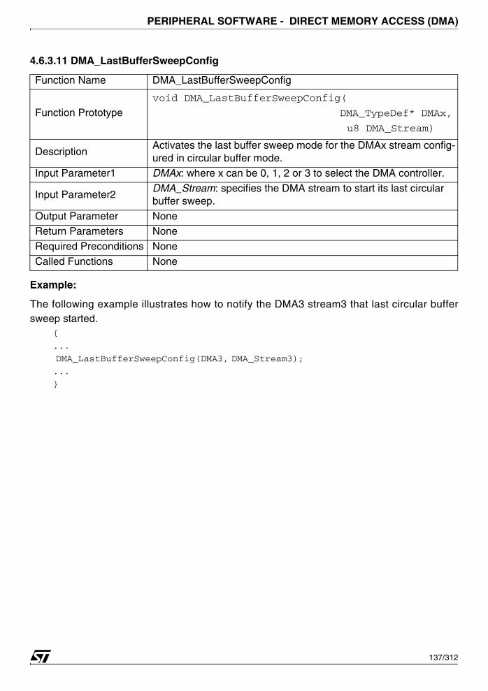
PERIPHERAL SOFTWARE - DIRECT MEMORY ACCESS (DMA)
4.6.3.11 DMA_LastBufferSweepConfig
Example:
The following example illustrates how to notify the DMA3 stream3 that last circular buffersweep started.
{
...
DMA_LastBufferSweepConfig(DMA3, DMA_Stream3);
...
}
Function Name DMA_LastBufferSweepConfig
Function Prototype
void DMA_LastBufferSweepConfig(
DMA_TypeDef* DMAx,
u8 DMA_Stream)
DescriptionActivates the last buffer sweep mode for the DMAx stream config-ured in circular buffer mode.
Input Parameter1 DMAx: where x can be 0, 1, 2 or 3 to select the DMA controller.
Input Parameter2DMA_Stream: specifies the DMA stream to start its last circular buffer sweep.
Output Parameter NoneReturn Parameters None
Required Preconditions None
Called Functions None
137/312

PERIPHERAL SOFTWARE - DIRECT MEMORY ACCESS (DMA)
4.6.3.12 DMA_LastBufferAddrConfig
Example:
The following example illustrates how to configure the circular buffer position where the lastdata to be used by the DMA3 stream3 is located.
{
u16 LastBufferAddr = 12;
...
DMA_LastBufferAddrConfig(DMA3, DMA_Stream3, LastBufferAddr);
...
}
Function Name DMA_LastBufferAddrConfig
Function Prototype
void
DMA_LastBufferAddrConfig(DMA_TypeDef* DMAx,
u8 DMA_Stream,
u16 LastBufferAddr)
DescriptionConfigures the circular buffer position where the last data to be used by the specified DMA stream is located.
Input Parameter1 DMAx: where x can be 0, 1, 2 or 3 to select the DMA controller.Input Parameter2 DMA_Stream: specifies the DMA stream to configure.
Input Parameter3LastBufferAddr: specifies the circular buffer position where the last data to be used by the specified DMA stream is located.
Output Parameter None
Return Parameters None
Required PreconditionsThis member must be a number between 0 and
DMA_InitStructure.DMA_BufferSize-1
Called Functions None
138/312
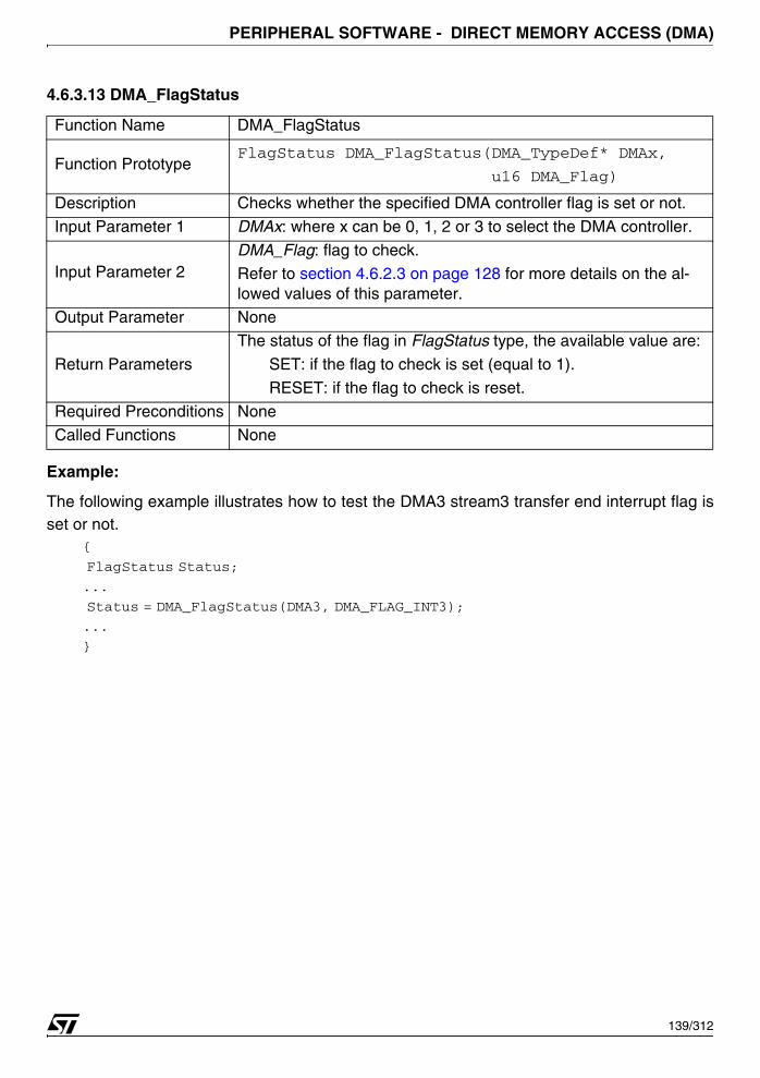
PERIPHERAL SOFTWARE - DIRECT MEMORY ACCESS (DMA)
4.6.3.13 DMA_FlagStatus
Example:
The following example illustrates how to test the DMA3 stream3 transfer end interrupt flag isset or not.
{
FlagStatus Status;
...
Status = DMA_FlagStatus(DMA3, DMA_FLAG_INT3);
...
}
Function Name DMA_FlagStatus
Function PrototypeFlagStatus DMA_FlagStatus(DMA_TypeDef* DMAx,
u16 DMA_Flag)
Description Checks whether the specified DMA controller flag is set or not.
Input Parameter 1 DMAx: where x can be 0, 1, 2 or 3 to select the DMA controller.
Input Parameter 2DMA_Flag: flag to check.Refer to section 4.6.2.3 on page 128 for more details on the al-lowed values of this parameter.
Output Parameter None
Return Parameters
The status of the flag in FlagStatus type, the available value are:
SET: if the flag to check is set (equal to 1).
RESET: if the flag to check is reset.
Required Preconditions None
Called Functions None
139/312
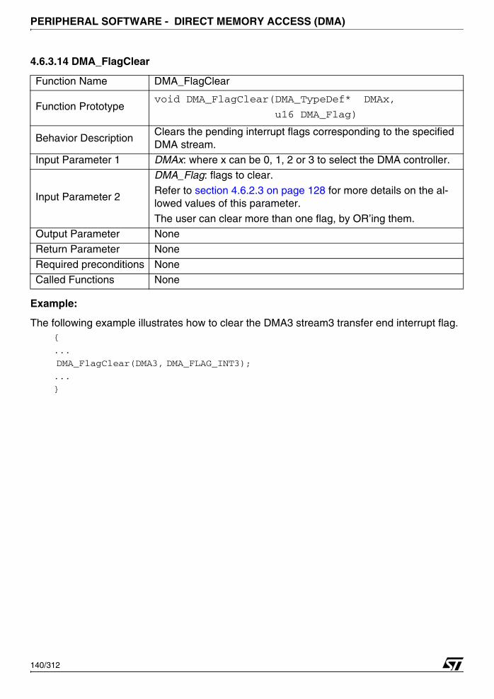
PERIPHERAL SOFTWARE - DIRECT MEMORY ACCESS (DMA)
4.6.3.14 DMA_FlagClear
Example:
The following example illustrates how to clear the DMA3 stream3 transfer end interrupt flag.{
...
DMA_FlagClear(DMA3, DMA_FLAG_INT3);
...
}
Function Name DMA_FlagClear
Function Prototypevoid DMA_FlagClear(DMA_TypeDef* DMAx,
u16 DMA_Flag)
Behavior DescriptionClears the pending interrupt flags corresponding to the specified DMA stream.
Input Parameter 1 DMAx: where x can be 0, 1, 2 or 3 to select the DMA controller.
Input Parameter 2
DMA_Flag: flags to clear.
Refer to section 4.6.2.3 on page 128 for more details on the al-lowed values of this parameter.
The user can clear more than one flag, by OR’ing them.Output Parameter None
Return Parameter None
Required preconditions None
Called Functions None
140/312
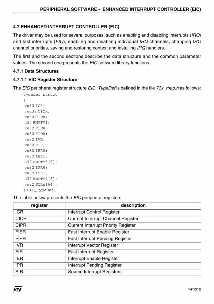
PERIPHERAL SOFTWARE - ENHANCED INTERRUPT CONTROLLER (EIC)
4.7 ENHANCED INTERRUPT CONTROLLER (EIC)
The driver may be used for several purposes, such as enabling and disabling interrupts (IRQ)and fast interrupts (FIQ), enabling and disabling individual IRQ channels, changing IRQchannel priorities, saving and restoring context and installing IRQ handlers.
The first and the second sections describe the data structure and the common parametervalues. The second one presents the EIC software library functions.
4.7.1 Data Structures
4.7.1.1 EIC Register Structure
The EIC peripheral register structure EIC_TypeDef is defined in the file 73x_map.h as follows:typedef struct
{
vu32 ICR;
vuc32 CICR;
vu32 CIPR;
u32 EMPTY1;
vu32 FIER;
vu32 FIPR;
vu32 IVR;
vu32 FIR;
vu32 IER0;
vu32 IER1;
u32 EMPTY3[6];
vu32 IPR0;
vu32 IPR1;
u32 EMPTY4[6];
vu32 SIRn[64];
} EIC_TypeDef;
The table below presents the EIC peripheral registers:
register descriptionICR Interrupt Control Register
CICR Current Interrupt Channel Register
CIPR Current Interrupt Priority Register
FIER Fast Interrupt Enable Register
FIPR Fast Interrupt Pending Register
IVR Interrupt Vector RegisterFIR Fast Interrupt Register
IER Interrupt Enable Register
IPR Interrupt Pending Register
SIR Source Interrupt Registers.
141/312
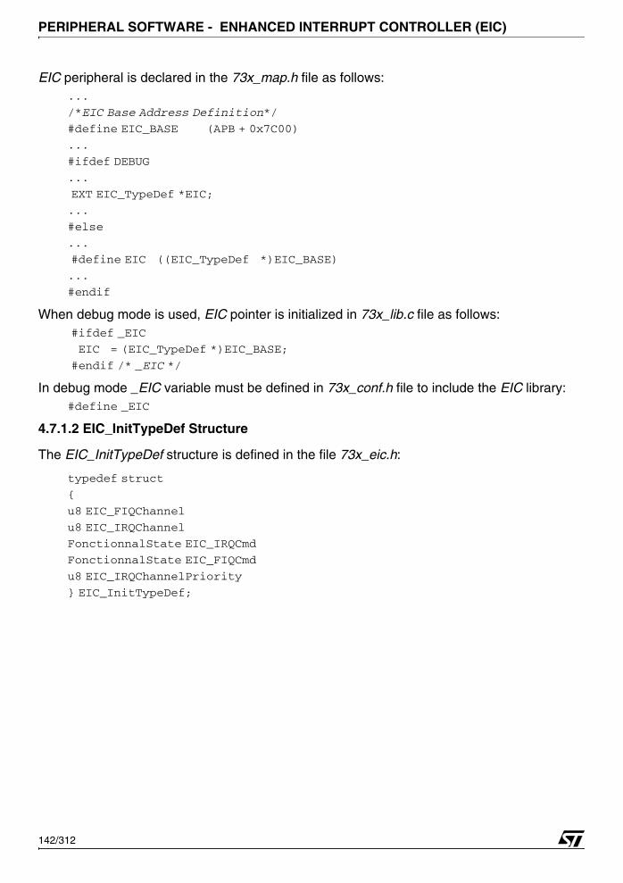
PERIPHERAL SOFTWARE - ENHANCED INTERRUPT CONTROLLER (EIC)
EIC peripheral is declared in the 73x_map.h file as follows:...
/*EIC Base Address Definition*/
#define EIC_BASE (APB + 0x7C00)
...
#ifdef DEBUG
...
EXT EIC_TypeDef *EIC;
...
#else
...
#define EIC ((EIC_TypeDef *)EIC_BASE)
...
#endif
When debug mode is used, EIC pointer is initialized in 73x_lib.c file as follows: #ifdef _EIC
EIC = (EIC_TypeDef *)EIC_BASE;
#endif /* _EIC */
In debug mode _EIC variable must be defined in 73x_conf.h file to include the EIC library:#define _EIC
4.7.1.2 EIC_InitTypeDef Structure
The EIC_InitTypeDef structure is defined in the file 73x_eic.h:
typedef struct
{
u8 EIC_FIQChannel
u8 EIC_IRQChannel
FonctionnalState EIC_IRQCmd
FonctionnalState EIC_FIQCmd
u8 EIC_IRQChannelPriority
} EIC_InitTypeDef;
142/312
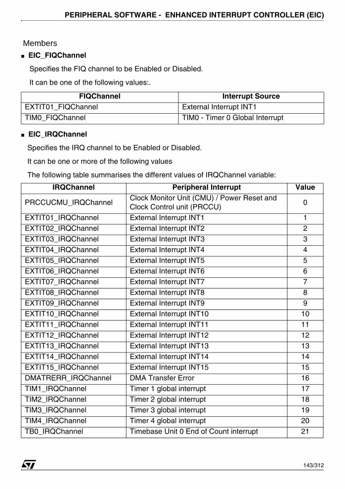
PERIPHERAL SOFTWARE - ENHANCED INTERRUPT CONTROLLER (EIC)
Members■ EIC_FIQChannel
Specifies the FIQ channel to be Enabled or Disabled.
It can be one of the following values:.
■ EIC_IRQChannel
Specifies the IRQ channel to be Enabled or Disabled.
It can be one or more of the following values
The following table summarises the different values of IRQChannel variable:
FIQChannel Interrupt SourceEXTIT01_FIQChannel External Interrupt INT1
TIM0_FIQChannel TIM0 - Timer 0 Global Interrupt
IRQChannel Peripheral Interrupt Value
PRCCUCMU_IRQChannelClock Monitor Unit (CMU) / Power Reset and Clock Control unit (PRCCU)
0
EXTIT01_IRQChannel External Interrupt INT1 1
EXTIT02_IRQChannel External Interrupt INT2 2
EXTIT03_IRQChannel External Interrupt INT3 3
EXTIT04_IRQChannel External Interrupt INT4 4
EXTIT05_IRQChannel External Interrupt INT5 5EXTIT06_IRQChannel External Interrupt INT6 6
EXTIT07_IRQChannel External Interrupt INT7 7
EXTIT08_IRQChannel External Interrupt INT8 8
EXTIT09_IRQChannel External Interrupt INT9 9
EXTIT10_IRQChannel External Interrupt INT10 10
EXTIT11_IRQChannel External Interrupt INT11 11
EXTIT12_IRQChannel External Interrupt INT12 12EXTIT13_IRQChannel External Interrupt INT13 13
EXTIT14_IRQChannel External Interrupt INT14 14
EXTIT15_IRQChannel External Interrupt INT15 15
DMATRERR_IRQChannel DMA Transfer Error 16
TIM1_IRQChannel Timer 1 global interrupt 17
TIM2_IRQChannel Timer 2 global interrupt 18TIM3_IRQChannel Timer 3 global interrupt 19
TIM4_IRQChannel Timer 4 global interrupt 20
TB0_IRQChannel Timebase Unit 0 End of Count interrupt 21
143/312

PERIPHERAL SOFTWARE - ENHANCED INTERRUPT CONTROLLER (EIC)
TB1_IRQChannel Timebase Unit 1 End of Count interrupt 22TB2_IRQChannel Timebase Unit 2 End of Count interrupt 23
TIM5_IRQChannel Timer 5 global interrupt 24
TIM6_IRQChannel Timer 6 global interrupt 25
TIM7_IRQChannel Timer 7 global interrupt 26
TIM8_IRQChannel Timer 8 global interrupt 27
TIM9_IRQChannel Timer 9 global interrupt 28UART2_IRQChannel UART 2 global interrupt 31
UART3_IRQChannel UART 3 global interrupt 32
FLASHEOP_IRQChannel Flash End of Write 33
PWM0_IRQChannel PWM 0 Compare Period Interrupt 34
PWM1_IRQChannel PWM 1 Compare Period Interrupt 35
PWM2_IRQChannel PWM 2 Compare Period Interrupt 36PWM3_IRQChannel PWM 3 Compare Period Interrupt 37
PWM4_IRQChannel PWM 4 Compare Period Interrupt 38
PWM5_IRQChannel PWM 5 Compare Period Interrupt 39
WIU_IRQChannel Wake-Up Unit Global Interrupt 40
WDGWUT_IRQChannelWatchdog Timer (WDG)
/Wake-Up Timer(WUT) End of Count41
BSPI0_IRQChannel BSPI 0 global interrupt 42BSPI1_IRQChannel BSPI 1 global interrupt 43
BSPI2_IRQChannel BSPI 2 global interrupt 44
UART0_IRQChannel UART 0 global interrupt 45
UART1_IRQChannel UART 1 global interrupt 46
I2C0ITERR_IRQChannel I2C 0 general/DMA interrupt 47
I2C1ITERR_IRQChannel I2C 1 general/DMA interrupt 48I2C0ITDDC_IRQChannel I2C 0 general interrupt 51
I2C1ITDDC_IRQChannel I2C 1 general interrupt 52
CAN0_IRQChannel CAN 0 global interrupt 55
CAN1_IRQChannel CAN 1 global interrupt 56
CAN2_IRQChannel CAN 2 global interrupt 57
DMA0_IRQChannel DMA 0 global interrupt 58
IRQChannel Peripheral Interrupt Value
144/312
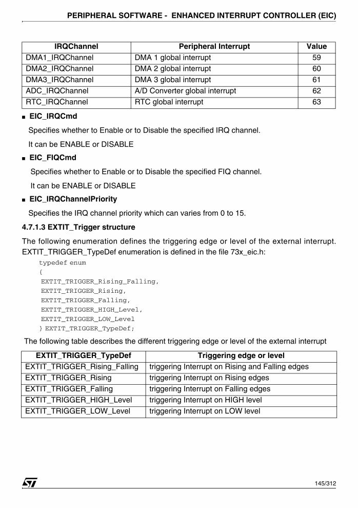
PERIPHERAL SOFTWARE - ENHANCED INTERRUPT CONTROLLER (EIC)
■ EIC_IRQCmd
Specifies whether to Enable or to Disable the specified IRQ channel.
It can be ENABLE or DISABLE
■ EIC_FIQCmd
Specifies whether to Enable or to Disable the specified FIQ channel.
It can be ENABLE or DISABLE
■ EIC_IRQChannelPriority
Specifies the IRQ channel priority which can varies from 0 to 15.
4.7.1.3 EXTIT_Trigger structure
The following enumeration defines the triggering edge or level of the external interrupt.EXTIT_TRIGGER_TypeDef enumeration is defined in the file 73x_eic.h:
typedef enum
{
EXTIT_TRIGGER_Rising_Falling,
EXTIT_TRIGGER_Rising,
EXTIT_TRIGGER_Falling,
EXTIT_TRIGGER_HIGH_Level,
EXTIT_TRIGGER_LOW_Level
} EXTIT_TRIGGER_TypeDef;
The following table describes the different triggering edge or level of the external interrupt
DMA1_IRQChannel DMA 1 global interrupt 59DMA2_IRQChannel DMA 2 global interrupt 60
DMA3_IRQChannel DMA 3 global interrupt 61
ADC_IRQChannel A/D Converter global interrupt 62
RTC_IRQChannel RTC global interrupt 63
EXTIT_TRIGGER_TypeDef Triggering edge or level EXTIT_TRIGGER_Rising_Falling triggering Interrupt on Rising and Falling edges
EXTIT_TRIGGER_Rising triggering Interrupt on Rising edges
EXTIT_TRIGGER_Falling triggering Interrupt on Falling edges
EXTIT_TRIGGER_HIGH_Level triggering Interrupt on HIGH level
EXTIT_TRIGGER_LOW_Level triggering Interrupt on LOW level
IRQChannel Peripheral Interrupt Value
145/312

PERIPHERAL SOFTWARE - ENHANCED INTERRUPT CONTROLLER (EIC)
4.7.2 Software Library Functions
The table below enumerates the different functions of the EIC library.
4.7.2.1 EIC_Init
Function Name Function Description
EIC_InitInitializes the EIC peripheral according to the specified parameters in the EIC_InitTypeDef structure.
EIC_DeInitDeinitializes the Interrupt Controller to be able to handle interrupt requests.
EIC_StructInitFills in a EIC_InitTypeDef structure with the reset value of each parameter.
EIC_CurrentPriorityLevelConfig Change the current priority level of the served IRQ routine
EIC_IRQChannelConfig Enable or Disable the selected IRQ Channel
EIC_ExternalITTriggerConfigSelect the edge or the level in which the external interrupt is issued
EIC_IRQCmd Enables or disables EIC IRQ output request to CPU.
EIC_FIQCmd Enables or disables EIC FIQ output request to CPU.
EIC_CurrentPriorityLevelValueReturns the current priority level of the current served IRQ routine
EIC_CurrentIRQChannelValue Returns the current served IRQ channel numberEIC_CurrentFIQChannelValue Returns the current served FIQ channel number
EIC_FIQPendingBitClear Clears the FIQ pending bit of the selected FIQ Channel
EIC_FIQChannelConfig Configure the FIQ Channel
EIC_IRQChannelPriorityConfig Configure the selected IRQ channel priority
EIC_ExternalITFilterConfig Enable or Disable a digital filter on external interrupt
Function Name EIC_Init
Function Prototype void EIC_Init(EIC_InitTypeDef* EIC_InitStruct)
Behavior DescriptionInitializes EIC peripheral according to the specified parameters in the EIC_InitTypeDef structure.
Input ParameterEIC_InitStruct: pointer to a EIC_InitTypeDef structure that contains the configuration information for the specified EIC peripheral.
Output Parameter None
Return Value None
Required preconditions None
Called Functions None
146/312

PERIPHERAL SOFTWARE - ENHANCED INTERRUPT CONTROLLER (EIC)
Example:
The following example illustrates how to configure the External interrupt 6 with priority 3 {
...
/* Initialize the EIC*/
EIC_InitStructure.EIC_IRQChannel = EXTIT06_IRQChannel;
EIC_InitStructure.EIC_FIQChannel = TIM0_FIQChannel;
EIC_InitStructure.EIC_IRQCmd = ENABLE;
EIC_InitStructure.EIC_FIQCmd = ENABLE;
EIC_InitStructure.EIC_IRQChannelPriority = 3;
EIC_Init (&EIC_InitStructure);
...
}
4.7.2.2 EIC_DeInit
Example:
The following example illustrates how to Initializes the Interrupt Controller to be able to handleinterrupt requests
{
...
/* Deinitialize the EIC*/
EIC_DeInit();
...
}
Function Name EIC_DeInit
Function Prototype void EIC_DeInit(void)
Behavior DescriptionInitializes the Interrupt Controller to be able with the str73x library architecture to handle the interrupt request
Input Parameter None
Output Parameter None
Return Value None
Required preconditions NoneCalled Functions None
147/312

PERIPHERAL SOFTWARE - ENHANCED INTERRUPT CONTROLLER (EIC)
4.7.2.3 EIC_StructInit
Example:
The following example illustrates how to initialize a EIC_InitTypeDef structure.{
EIC_InitTypeDef EIC_InitStructure;
EIC_StructInit(&EIC_InitStructure);
}
4.7.2.4 EIC_CurrentPriorityLevelConfig
Example:
The following example illustrates how reconfigure the current priority level to 15.{
...
EIC_CurrentPriorityLevelConfig(0x0F);
...
}
Function Name EIC_StructInit
Function Prototypevoid EIC_StructInit(EIC_InitTypeDef* EIC_InitStruct)
Behavior DescriptionFills in the structure with the reset value of each parameter (which depend on the register reset value).
Input ParameterEIC_InitStruct: pointer to a EIC_InitTypeDef structure which will be initialized.
Output Parameter None
Return Value NoneRequired preconditions None
Called Functions None
Function Name EIC_CurrentPriorityLevelConfig
Function Prototypevoid EIC_CurrentPriorityLevelConfig(u8 NewPriorityLevel)
Behavior Description Change the current priority level of the served IRQ routine
Input Parameter NewPriorityLevel: New current priority.
Output Parameter None
Return Value None
Required preconditions The new priority level must be higher than the current priority level.Called Functions None
148/312
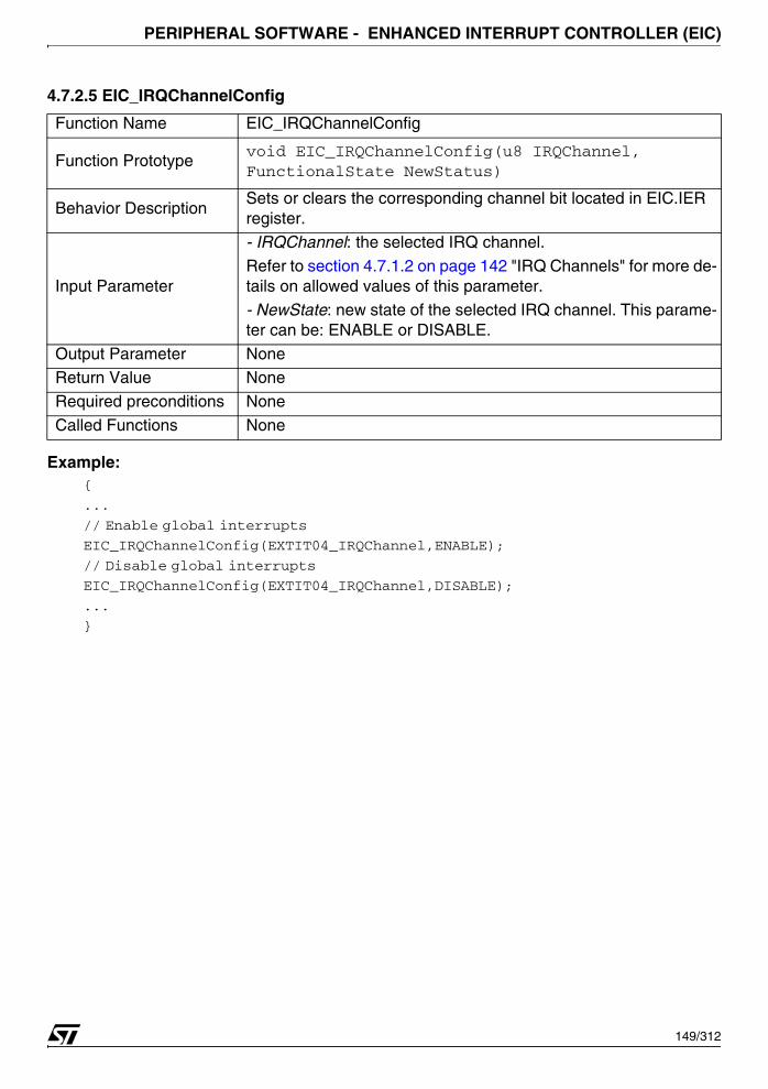
PERIPHERAL SOFTWARE - ENHANCED INTERRUPT CONTROLLER (EIC)
4.7.2.5 EIC_IRQChannelConfig
Example:{
...
// Enable global interrupts
EIC_IRQChannelConfig(EXTIT04_IRQChannel,ENABLE);
// Disable global interrupts
EIC_IRQChannelConfig(EXTIT04_IRQChannel,DISABLE);
...
}
Function Name EIC_IRQChannelConfig
Function Prototypevoid EIC_IRQChannelConfig(u8 IRQChannel, FunctionalState NewStatus)
Behavior DescriptionSets or clears the corresponding channel bit located in EIC.IER register.
Input Parameter
- IRQChannel: the selected IRQ channel.
Refer to section 4.7.1.2 on page 142 "IRQ Channels" for more de-tails on allowed values of this parameter.
- NewState: new state of the selected IRQ channel. This parame-ter can be: ENABLE or DISABLE.
Output Parameter NoneReturn Value None
Required preconditions None
Called Functions None
149/312
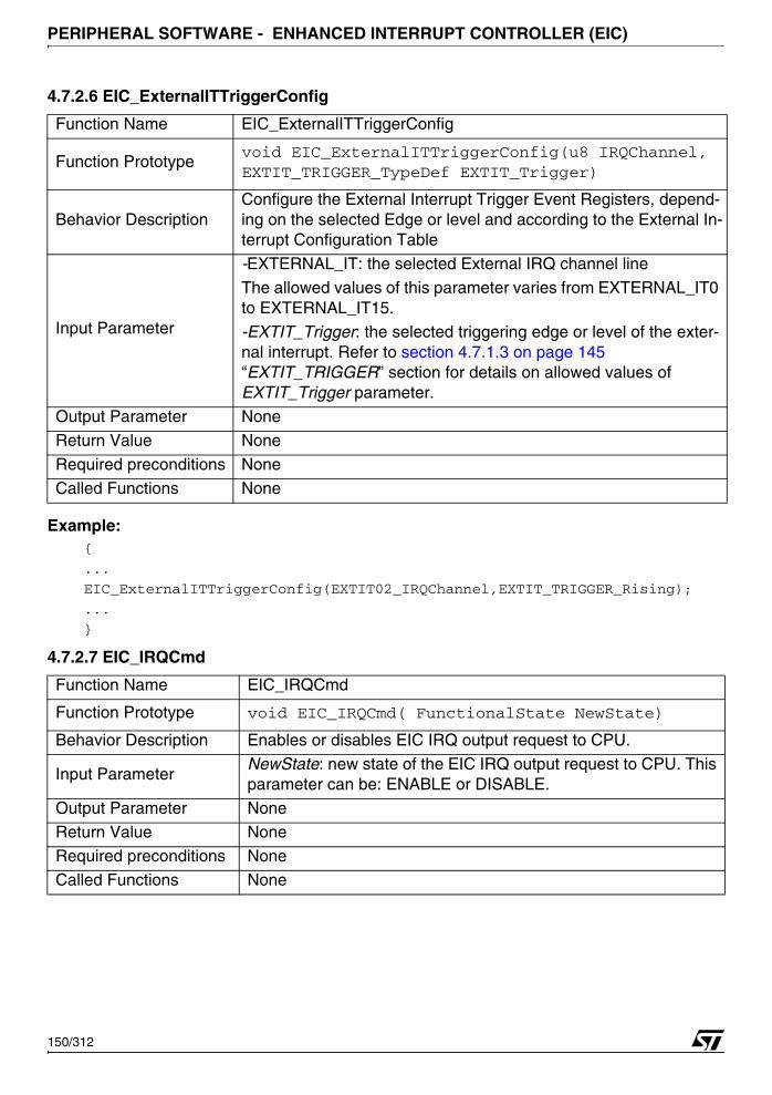
PERIPHERAL SOFTWARE - ENHANCED INTERRUPT CONTROLLER (EIC)
4.7.2.6 EIC_ExternalITTriggerConfig
Example:{
...
EIC_ExternalITTriggerConfig(EXTIT02_IRQChannel,EXTIT_TRIGGER_Rising);
...
}
4.7.2.7 EIC_IRQCmd
Function Name EIC_ExternalITTriggerConfig
Function Prototypevoid EIC_ExternalITTriggerConfig(u8 IRQChannel, EXTIT_TRIGGER_TypeDef EXTIT_Trigger)
Behavior DescriptionConfigure the External Interrupt Trigger Event Registers, depend-ing on the selected Edge or level and according to the External In-terrupt Configuration Table
Input Parameter
-EXTERNAL_IT: the selected External IRQ channel line
The allowed values of this parameter varies from EXTERNAL_IT0 to EXTERNAL_IT15.
-EXTIT_Trigger: the selected triggering edge or level of the exter-nal interrupt. Refer to section 4.7.1.3 on page 145 “EXTIT_TRIGGER” section for details on allowed values of EXTIT_Trigger parameter.
Output Parameter None
Return Value None
Required preconditions None
Called Functions None
Function Name EIC_IRQCmd
Function Prototype void EIC_IRQCmd( FunctionalState NewState)
Behavior Description Enables or disables EIC IRQ output request to CPU.
Input ParameterNewState: new state of the EIC IRQ output request to CPU. This parameter can be: ENABLE or DISABLE.
Output Parameter NoneReturn Value None
Required preconditions None
Called Functions None
150/312

PERIPHERAL SOFTWARE - ENHANCED INTERRUPT CONTROLLER (EIC)
Example:
The following example illustrates how to enable global IRQ interrupt.{
EIC_IRQCmd(ENABLE);
}
4.7.2.8 EIC_FIQCmd
Example:
The following example illustrates how to enable the FIQ interrupt to be recognized by the EIC. {
EIC_FIQCmd(ENABLE);
}
4.7.2.9 EIC_CurrentPriorityLevelValue
Example:
The following example illustrates how to get the priority of the served interrupt. {
u8 bCurrentPriorityLeveValue;
bCurrentPriorityLeveValue = EIC_CurrentPriorityLevelValue();
}
Function Name EIC_FIQCmd
Function Prototype void EIC_FIQCmd( FunctionalState NewState)
Behavior Description Enables or disables EIC FIQ output request to CPU
Input ParameterNewState: new state of the EIC FIQ output request to CPU. This parameter can be: ENABLE or DISABLE.
Output Parameter None
Return Value None
Required preconditions None
Called Functions None
Function Name EIC_CurrentPriorityLevelValue
Function Prototype u8 EIC_CurrentPriorityLevelValue(void)
Behavior DescriptionReturns the current priority level of the current served IRQ
routine
Input Parameter None
Output Parameter None
Return Value The current priority level
Required preconditions None
Called Functions None
151/312
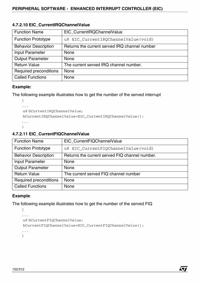
PERIPHERAL SOFTWARE - ENHANCED INTERRUPT CONTROLLER (EIC)
4.7.2.10 EIC_CurrentIRQChannelValue
Example:
The following example illustrates how to get the number of the served interrupt {
...
u8 bCurrentIRQChannelValue;
bCurrentIRQChannelValue=EIC_CurrentIRQChannelValue();
...
}
4.7.2.11 EIC_CurrentFIQChannelValue
Example:
The following example illustrates how to get the number of the served FIQ{
...
u8 bCurrentFIQChannelValue;
bCurrentFIQChannelValue=EIC_CurrentFIQChannelValue();
...
}
Function Name EIC_CurrentIRQChannelValue
Function Prototype u8 EIC_CurrentIRQChannelValue(void)
Behavior Description Returns the current served IRQ channel numberInput Parameter None
Output Parameter None
Return Value The current served IRQ channel number.
Required preconditions None
Called Functions None
Function Name EIC_CurrentFIQChannelValue
Function Prototype u8 EIC_CurrentFIQChannelValue(void)
Behavior Description Returns the current served FIQ channel number.
Input Parameter NoneOutput Parameter None
Return Value The current served FIQ channel number
Required preconditions None
Called Functions None
152/312
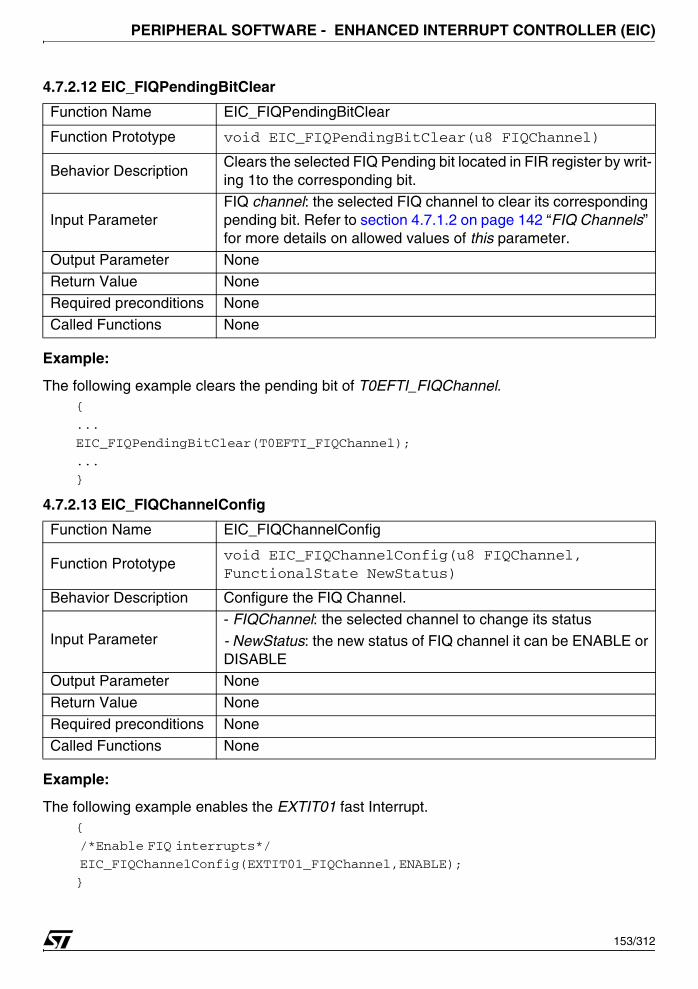
PERIPHERAL SOFTWARE - ENHANCED INTERRUPT CONTROLLER (EIC)
4.7.2.12 EIC_FIQPendingBitClear
Example:
The following example clears the pending bit of T0EFTI_FIQChannel.{
...
EIC_FIQPendingBitClear(T0EFTI_FIQChannel);
...
}
4.7.2.13 EIC_FIQChannelConfig
Example:
The following example enables the EXTIT01 fast Interrupt.{
/*Enable FIQ interrupts*/
EIC_FIQChannelConfig(EXTIT01_FIQChannel,ENABLE);
}
Function Name EIC_FIQPendingBitClear
Function Prototype void EIC_FIQPendingBitClear(u8 FIQChannel)
Behavior DescriptionClears the selected FIQ Pending bit located in FIR register by writ-ing 1to the corresponding bit.
Input ParameterFIQ channel: the selected FIQ channel to clear its corresponding pending bit. Refer to section 4.7.1.2 on page 142 “FIQ Channels” for more details on allowed values of this parameter.
Output Parameter None
Return Value NoneRequired preconditions None
Called Functions None
Function Name EIC_FIQChannelConfig
Function Prototypevoid EIC_FIQChannelConfig(u8 FIQChannel, FunctionalState NewStatus)
Behavior Description Configure the FIQ Channel.
Input Parameter- FIQChannel: the selected channel to change its status
- NewStatus: the new status of FIQ channel it can be ENABLE or DISABLE
Output Parameter None
Return Value None
Required preconditions None
Called Functions None
153/312
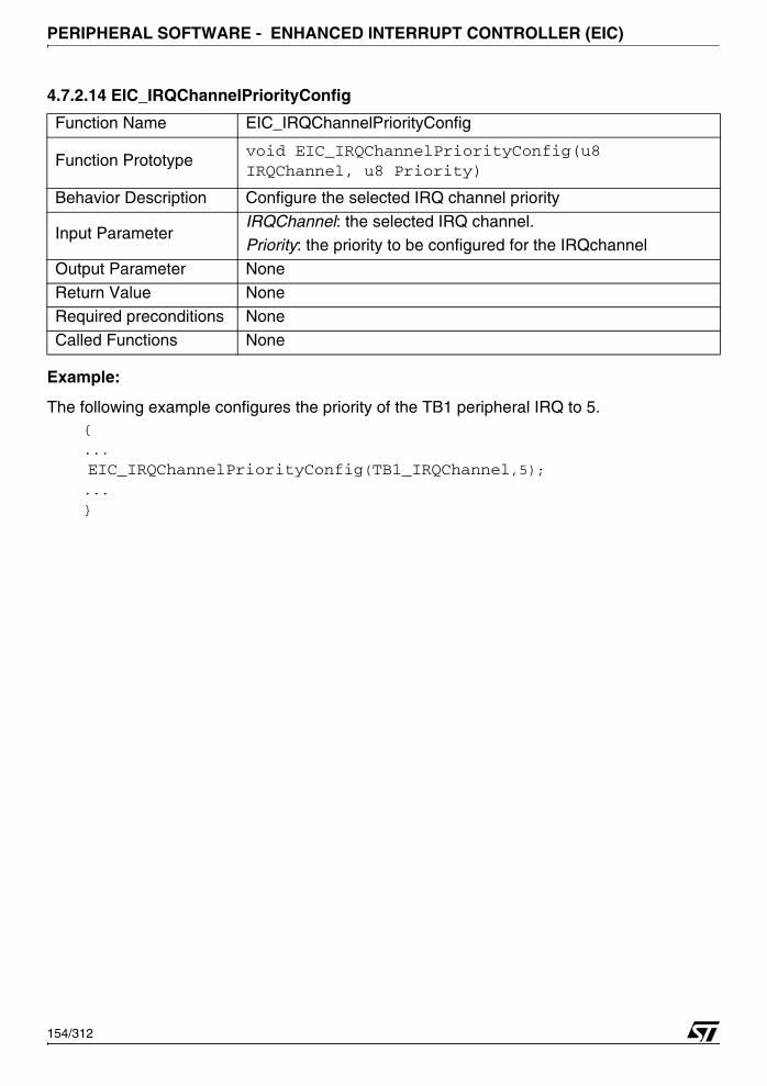
PERIPHERAL SOFTWARE - ENHANCED INTERRUPT CONTROLLER (EIC)
4.7.2.14 EIC_IRQChannelPriorityConfig
Example:
The following example configures the priority of the TB1 peripheral IRQ to 5.{
...
EIC_IRQChannelPriorityConfig(TB1_IRQChannel,5);...
}
Function Name EIC_IRQChannelPriorityConfig
Function Prototypevoid EIC_IRQChannelPriorityConfig(u8 IRQChannel, u8 Priority)
Behavior Description Configure the selected IRQ channel priority
Input ParameterIRQChannel: the selected IRQ channel.Priority: the priority to be configured for the IRQchannel
Output Parameter None
Return Value None
Required preconditions None
Called Functions None
154/312
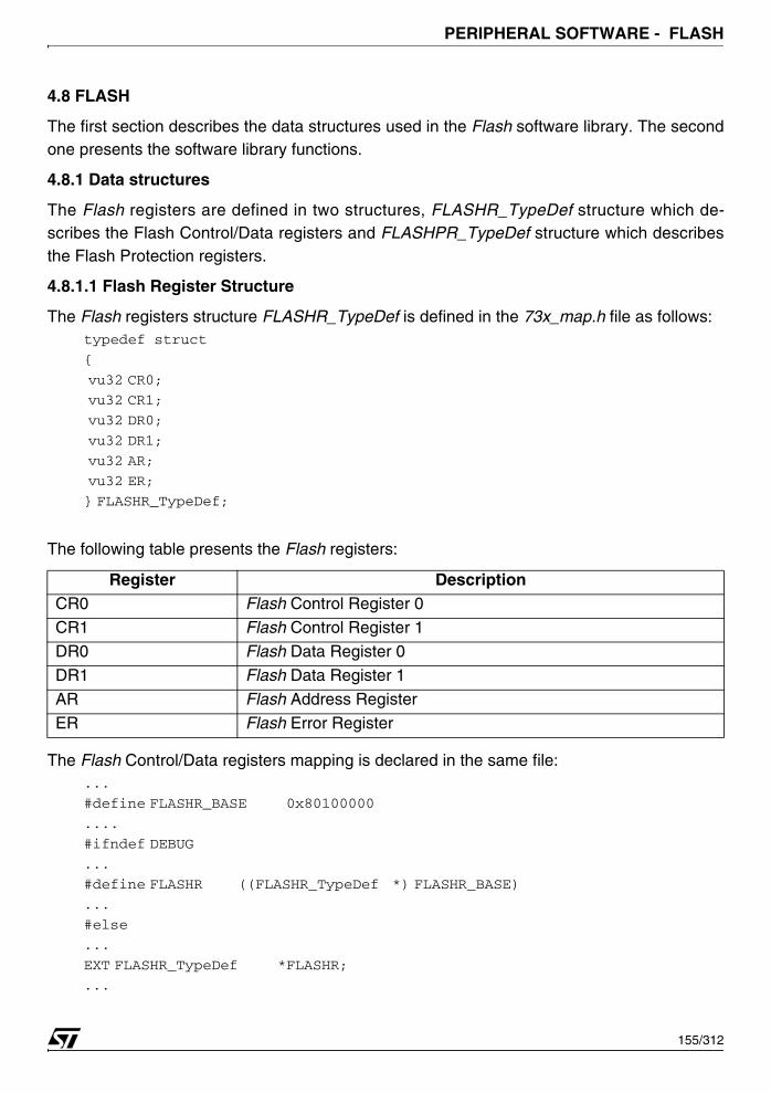
PERIPHERAL SOFTWARE - FLASH
4.8 FLASH
The first section describes the data structures used in the Flash software library. The secondone presents the software library functions.
4.8.1 Data structures
The Flash registers are defined in two structures, FLASHR_TypeDef structure which de-scribes the Flash Control/Data registers and FLASHPR_TypeDef structure which describesthe Flash Protection registers.
4.8.1.1 Flash Register Structure
The Flash registers structure FLASHR_TypeDef is defined in the 73x_map.h file as follows: typedef struct
{
vu32 CR0;
vu32 CR1;
vu32 DR0;
vu32 DR1;
vu32 AR;
vu32 ER;
} FLASHR_TypeDef;
The following table presents the Flash registers:
The Flash Control/Data registers mapping is declared in the same file:...
#define FLASHR_BASE 0x80100000
....
#ifndef DEBUG
...
#define FLASHR ((FLASHR_TypeDef *) FLASHR_BASE)
...
#else
...
EXT FLASHR_TypeDef *FLASHR;
...
Register DescriptionCR0 Flash Control Register 0
CR1 Flash Control Register 1
DR0 Flash Data Register 0
DR1 Flash Data Register 1
AR Flash Address Register
ER Flash Error Register
155/312
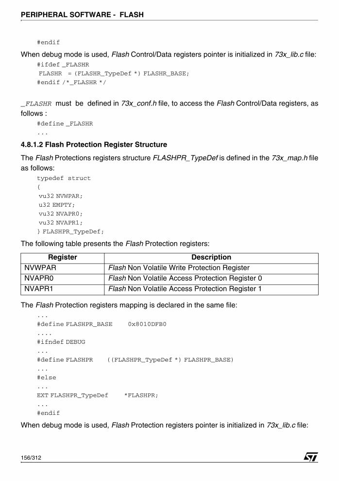
PERIPHERAL SOFTWARE - FLASH
#endif
When debug mode is used, Flash Control/Data registers pointer is initialized in 73x_lib.c file:#ifdef _FLASHR
FLASHR = (FLASHR_TypeDef *) FLASHR_BASE;
#endif /*_FLASHR */
_FLASHR must be defined in 73x_conf.h file, to access the Flash Control/Data registers, asfollows :
#define _FLASHR
...
4.8.1.2 Flash Protection Register Structure
The Flash Protections registers structure FLASHPR_TypeDef is defined in the 73x_map.h fileas follows:
typedef struct
{
vu32 NVWPAR;
u32 EMPTY;
vu32 NVAPR0;
vu32 NVAPR1;
} FLASHPR_TypeDef;
The following table presents the Flash Protection registers:
The Flash Protection registers mapping is declared in the same file:...
#define FLASHPR_BASE 0x8010DFB0
....
#ifndef DEBUG
...
#define FLASHPR ((FLASHPR_TypeDef *) FLASHPR_BASE)
...
#else
...
EXT FLASHPR_TypeDef *FLASHPR;
...
#endif
When debug mode is used, Flash Protection registers pointer is initialized in 73x_lib.c file:
Register DescriptionNVWPAR Flash Non Volatile Write Protection RegisterNVAPR0 Flash Non Volatile Access Protection Register 0
NVAPR1 Flash Non Volatile Access Protection Register 1
156/312
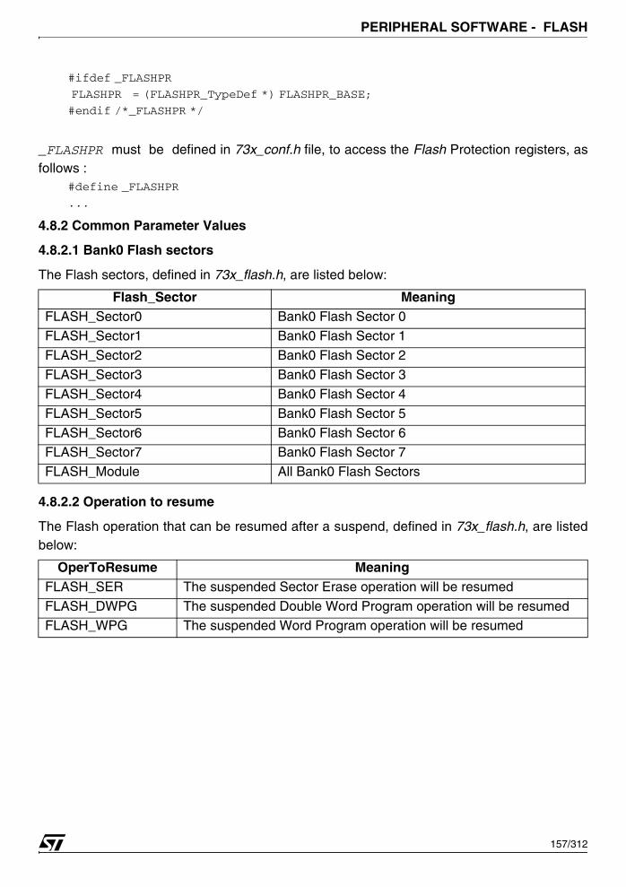
PERIPHERAL SOFTWARE - FLASH
#ifdef _FLASHPR
FLASHPR = (FLASHPR_TypeDef *) FLASHPR_BASE;
#endif /*_FLASHPR */
_FLASHPR must be defined in 73x_conf.h file, to access the Flash Protection registers, asfollows :
#define _FLASHPR
...
4.8.2 Common Parameter Values
4.8.2.1 Bank0 Flash sectors
The Flash sectors, defined in 73x_flash.h, are listed below:
4.8.2.2 Operation to resume
The Flash operation that can be resumed after a suspend, defined in 73x_flash.h, are listedbelow:
Flash_Sector MeaningFLASH_Sector0 Bank0 Flash Sector 0
FLASH_Sector1 Bank0 Flash Sector 1
FLASH_Sector2 Bank0 Flash Sector 2
FLASH_Sector3 Bank0 Flash Sector 3
FLASH_Sector4 Bank0 Flash Sector 4
FLASH_Sector5 Bank0 Flash Sector 5
FLASH_Sector6 Bank0 Flash Sector 6FLASH_Sector7 Bank0 Flash Sector 7
FLASH_Module All Bank0 Flash Sectors
OperToResume MeaningFLASH_SER The suspended Sector Erase operation will be resumed
FLASH_DWPG The suspended Double Word Program operation will be resumed FLASH_WPG The suspended Word Program operation will be resumed
157/312

PERIPHERAL SOFTWARE - FLASH
4.8.2.3 Flash flags
The Flash flags, defined in 73x_flash.h, are listed below:
(1): parameters for FLASH_FlagStatus() function.(2): parameters for FLASH_FlagClear() function only.
4.8.3 Software Library Functions
The following table enumerates the different functions of the Flash library.
FLASH_FLAG MeaningFLASH_FLAG_BSY0(1) Bank0 busy flag
FLASH_FLAG_LOCK(1) Flash register access locked flag
FLASH_FLAG_JBL(1)(2) JTAG boot mode latched flag
FLASH_FLAG_INTP(1)(2) End of write interrupt pending flag
FLASH_FLAG_BSM(1)(2) Boot from system memory flagFLASH_FLAG_ERR(1)(2) Write error flag
FLASH_FLAG_ERER(1)(2) Erase error flag
FLASH_FLAG_PGER(1)(2) Program error flag
FLASH_FLAG_10ER(1)(2) 1 over 0 error flag
FLASH_FLAG_SEQER(1)(2) Sequence error flag
FLASH_FLAG_RESER(1)(2) Resume error flagFLASH_FLAG_WPF(1)(2) Write protection flag
Function Name Description
FLASH_DeInitDeinitializes Flash module registers to their default reset val-ues.
FLASH_WordWrite Writes a word at the specified address in the Flash.
FLASH_DWordWrite Writes a double word at the specified address in the Flash.
FLASH_BlockWrite Writes a block of data from the RAM to the Flash.
FLASH_WordRead Reads a word from the specified address in the Flash.
FLASH_BlockRead Reads a block of data from the Flash and store it in the RAM.
FLASH_SectorErase Erases the specified Flash sectors.FLASH_Suspend Suspends an on-going operation on the Flash.
FLASH_Resume Resumes a suspended operation on the Flash.
FLASH_PowerDownConfig Enables or disables the Flash power down mode.
FLASH_ITConfig Enables or disables the end of write interrupt(INTM).
FLASH_FlagStatus Checks whether the specified Flash flag is set or not.
FLASH_FlagClear Clears the specified Flash flag.
FLASH_WaitForLastTask Waits for the end of last task.
158/312
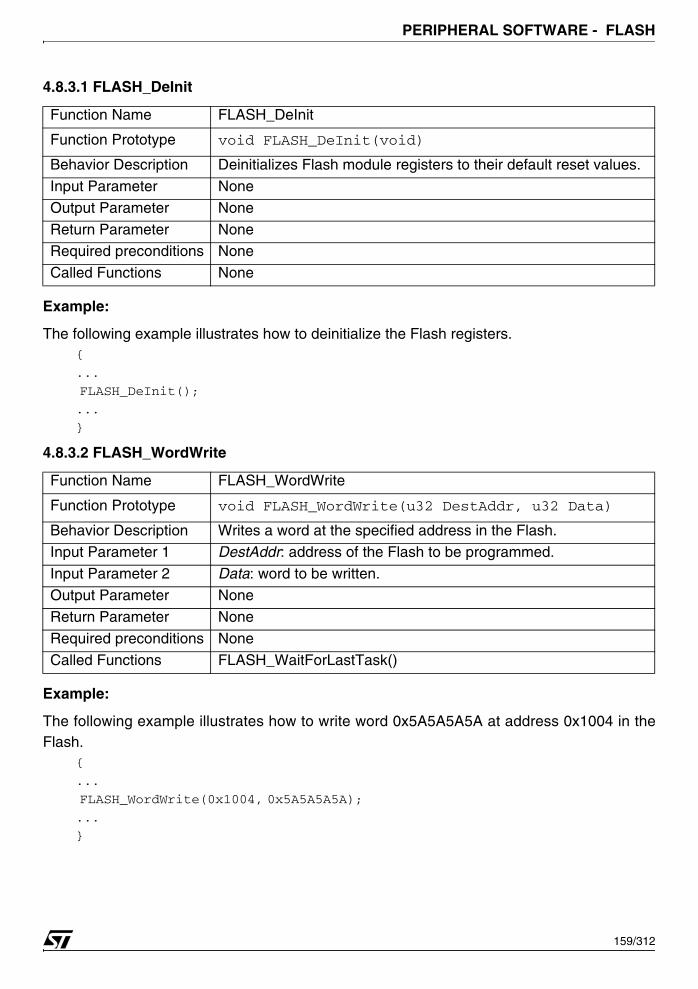
PERIPHERAL SOFTWARE - FLASH
4.8.3.1 FLASH_DeInit
Example:
The following example illustrates how to deinitialize the Flash registers.{
...
FLASH_DeInit();
...
}
4.8.3.2 FLASH_WordWrite
Example:
The following example illustrates how to write word 0x5A5A5A5A at address 0x1004 in theFlash.
{
...
FLASH_WordWrite(0x1004, 0x5A5A5A5A);
...
}
Function Name FLASH_DeInit
Function Prototype void FLASH_DeInit(void)
Behavior Description Deinitializes Flash module registers to their default reset values.
Input Parameter None
Output Parameter None
Return Parameter NoneRequired preconditions None
Called Functions None
Function Name FLASH_WordWrite
Function Prototype void FLASH_WordWrite(u32 DestAddr, u32 Data)
Behavior Description Writes a word at the specified address in the Flash.Input Parameter 1 DestAddr: address of the Flash to be programmed.
Input Parameter 2 Data: word to be written.
Output Parameter None
Return Parameter None
Required preconditions None
Called Functions FLASH_WaitForLastTask()
159/312
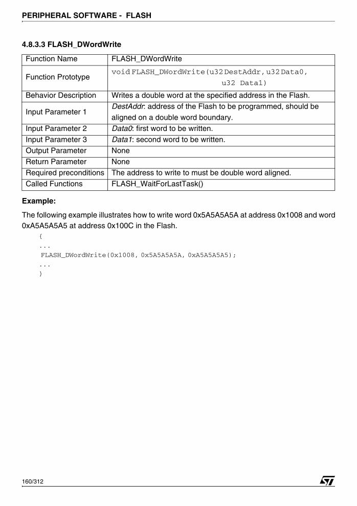
PERIPHERAL SOFTWARE - FLASH
4.8.3.3 FLASH_DWordWrite
Example:
The following example illustrates how to write word 0x5A5A5A5A at address 0x1008 and word0xA5A5A5A5 at address 0x100C in the Flash.
{
...
FLASH_DWordWrite(0x1008, 0x5A5A5A5A, 0xA5A5A5A5);
...
}
Function Name FLASH_DWordWrite
Function Prototypevoid FLASH_DWordWrite(u32 DestAddr, u32 Data0,
u32 Data1)
Behavior Description Writes a double word at the specified address in the Flash.
Input Parameter 1DestAddr: address of the Flash to be programmed, should be
aligned on a double word boundary.Input Parameter 2 Data0: first word to be written.
Input Parameter 3 Data1: second word to be written.
Output Parameter None
Return Parameter None
Required preconditions The address to write to must be double word aligned.
Called Functions FLASH_WaitForLastTask()
160/312

PERIPHERAL SOFTWARE - FLASH
4.8.3.4 FLASH_BlockWrite
Example:
The following example illustrates how to copy a buffer of four words from the RAM to theFlash.
{
u32 SRC_Buffer[4] = {0x5A5A5A5A, 0xA5A5A5A5, 0x55AA55AA, 0xAA55AA55}
...
FLASH_BlockWrite((u32)&SRC_Buffer, 0x2000, 4);
...
}
4.8.3.5 FLASH_WordRead
Example:
The following example illustrates how to read a word from address 0x1004 in the Flash.
Function Name FLASH_BlockWrite
Function Prototype
void FLASH_BlockWrite(u32 SourceAddr,
u32 DestAddr,
u32 NbrWordToWrite)
Behavior Description Writes a block of data from the RAM to the Flash.
Input Parameter 1SourceAddr : specifies the RAM address of the block of data to be programmed in the Flash.
Input Parameter 2DestAddr: specifies the address in the Flash where the block of data will be programmed.
Input Parameter 3NbrWordToWrite: specifies the number of data to be programmed expressed in terms of words.
Output Parameter NoneReturn Parameter None
Required preconditions None
Called Functions FLASH_DWordWrite() and FLASH_WordWrite().
Function Name FLASH_WordRead
Function Prototype u32 FLASH_WordRead(u32 SourceAddr)
Behavior Description Reads a word from the specified address in the Flash.
Input Parameter SourceAddr: address of the Flash to be read.
Output Parameter None
Return Parameter The data value at the specified address.Required preconditions None
Called Functions FLASH_WaitForLastTask()
161/312
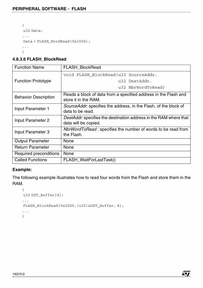
PERIPHERAL SOFTWARE - FLASH
{
u32 Data;
...
Data = FLASH_WordRead(0x1004);
...
}
4.8.3.6 FLASH_BlockRead
Example:
The following example illustrates how to read four words from the Flash and store them in theRAM.
{
u32 DST_Buffer[4];
...
FLASH_BlockRead(0x2000,(u32)&DST_Buffer, 4);
...
}
Function Name FLASH_BlockRead
Function Prototype
void FLASH_BlockRead(u32 SourceAddr,
u32 DestAddr,
u32 NbrWordToRead)
Behavior DescriptionReads a block of data from a specified address in the Flash and store it in the RAM.
Input Parameter 1SourceAddr: specifies the address, in the Flash, of the block of data to be read.
Input Parameter 2DestAddr: specifies the destination address in the RAM where that data will be copied.
Input Parameter 3NbrWordToRead : specifies the number of words to be read from the Flash.
Output Parameter None
Return Parameter None
Required preconditions None
Called Functions FLASH_WaitForLastTask()
162/312
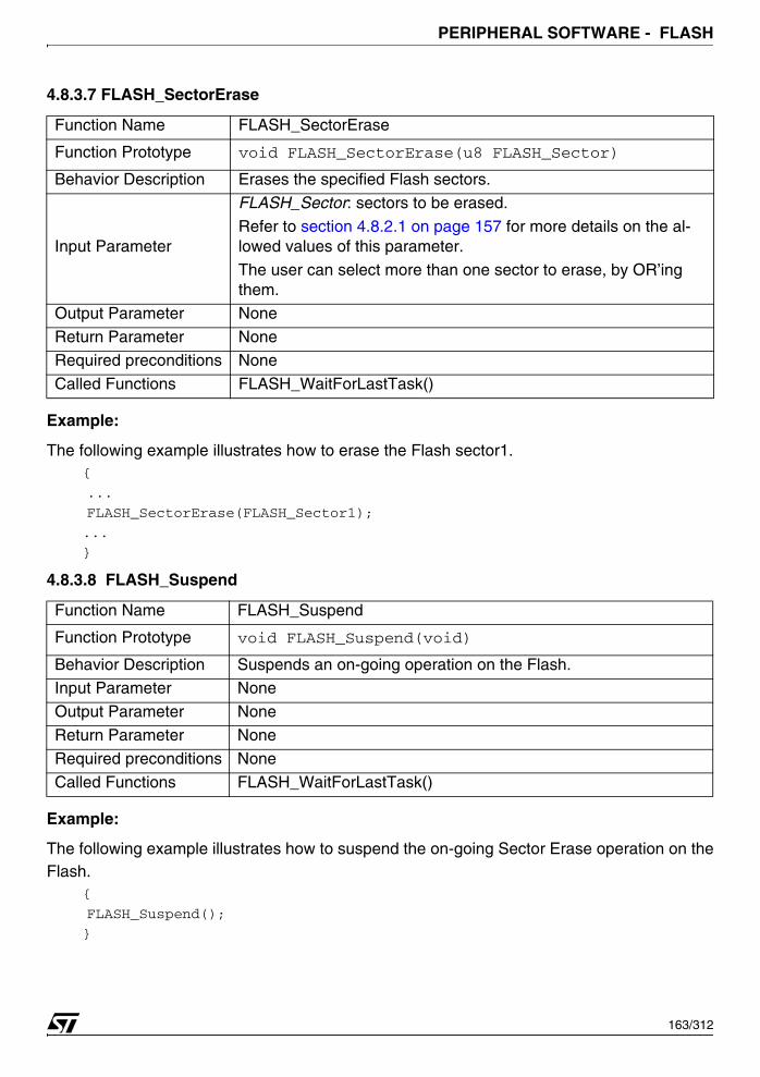
PERIPHERAL SOFTWARE - FLASH
4.8.3.7 FLASH_SectorErase
Example:
The following example illustrates how to erase the Flash sector1.{
...
FLASH_SectorErase(FLASH_Sector1);
...
}
4.8.3.8 FLASH_Suspend
Example:
The following example illustrates how to suspend the on-going Sector Erase operation on theFlash.
{
FLASH_Suspend();
}
Function Name FLASH_SectorErase
Function Prototype void FLASH_SectorErase(u8 FLASH_Sector)
Behavior Description Erases the specified Flash sectors.
Input Parameter
FLASH_Sector: sectors to be erased.
Refer to section 4.8.2.1 on page 157 for more details on the al-lowed values of this parameter.
The user can select more than one sector to erase, by OR’ing them.
Output Parameter None
Return Parameter NoneRequired preconditions None
Called Functions FLASH_WaitForLastTask()
Function Name FLASH_Suspend
Function Prototype void FLASH_Suspend(void)
Behavior Description Suspends an on-going operation on the Flash.Input Parameter None
Output Parameter None
Return Parameter None
Required preconditions None
Called Functions FLASH_WaitForLastTask()
163/312
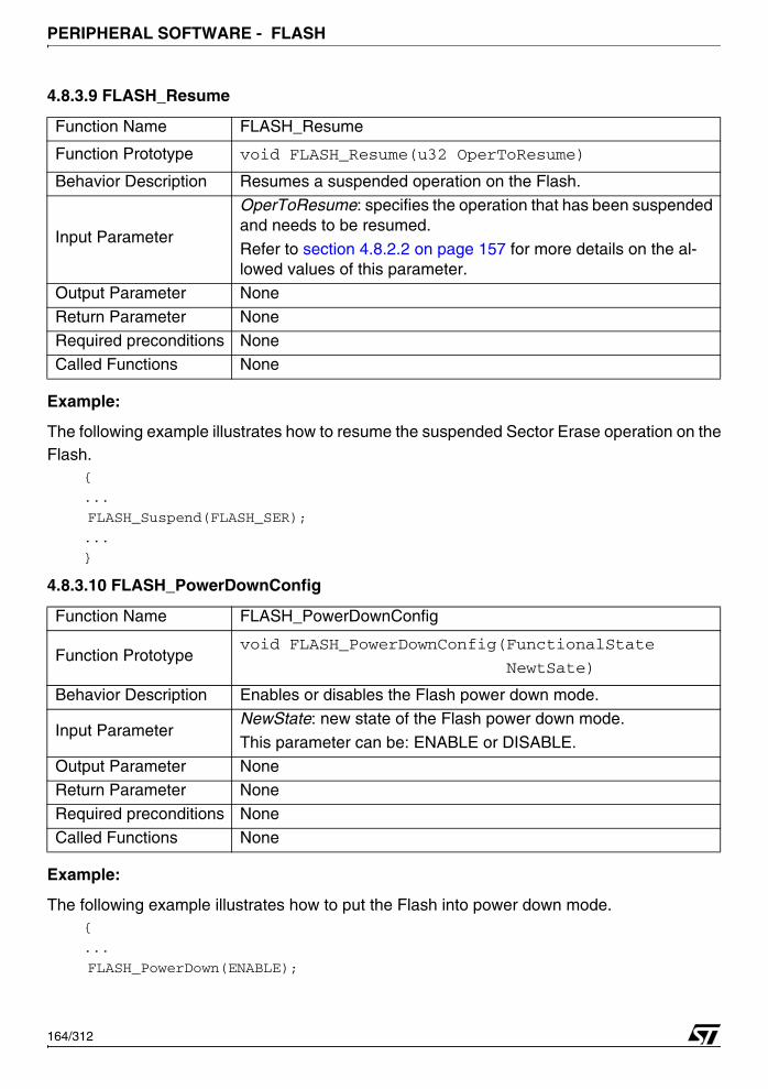
PERIPHERAL SOFTWARE - FLASH
4.8.3.9 FLASH_Resume
Example:
The following example illustrates how to resume the suspended Sector Erase operation on theFlash.
{
...
FLASH_Suspend(FLASH_SER);
...
}
4.8.3.10 FLASH_PowerDownConfig
Example:
The following example illustrates how to put the Flash into power down mode.{
...
FLASH_PowerDown(ENABLE);
Function Name FLASH_Resume
Function Prototype void FLASH_Resume(u32 OperToResume)
Behavior Description Resumes a suspended operation on the Flash.
Input Parameter
OperToResume: specifies the operation that has been suspended and needs to be resumed.
Refer to section 4.8.2.2 on page 157 for more details on the al-lowed values of this parameter.
Output Parameter None
Return Parameter None
Required preconditions NoneCalled Functions None
Function Name FLASH_PowerDownConfig
Function Prototypevoid FLASH_PowerDownConfig(FunctionalState
NewtSate)
Behavior Description Enables or disables the Flash power down mode.
Input ParameterNewState: new state of the Flash power down mode.
This parameter can be: ENABLE or DISABLE.
Output Parameter NoneReturn Parameter None
Required preconditions None
Called Functions None
164/312
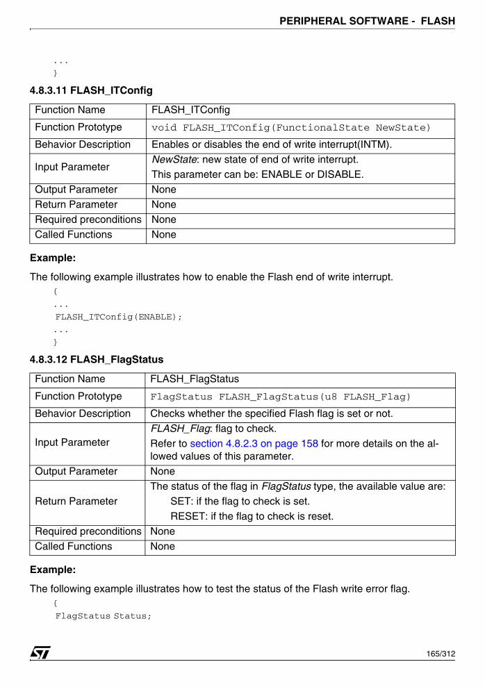
PERIPHERAL SOFTWARE - FLASH
...
}
4.8.3.11 FLASH_ITConfig
Example:
The following example illustrates how to enable the Flash end of write interrupt.{
...
FLASH_ITConfig(ENABLE);
...
}
4.8.3.12 FLASH_FlagStatus
Example:
The following example illustrates how to test the status of the Flash write error flag.{
FlagStatus Status;
Function Name FLASH_ITConfig
Function Prototype void FLASH_ITConfig(FunctionalState NewState)
Behavior Description Enables or disables the end of write interrupt(INTM).
Input ParameterNewState: new state of end of write interrupt. This parameter can be: ENABLE or DISABLE.
Output Parameter None
Return Parameter None
Required preconditions None
Called Functions None
Function Name FLASH_FlagStatus
Function Prototype FlagStatus FLASH_FlagStatus(u8 FLASH_Flag)
Behavior Description Checks whether the specified Flash flag is set or not.
Input ParameterFLASH_Flag: flag to check.
Refer to section 4.8.2.3 on page 158 for more details on the al-lowed values of this parameter.
Output Parameter None
Return ParameterThe status of the flag in FlagStatus type, the available value are: SET: if the flag to check is set.
RESET: if the flag to check is reset.
Required preconditions None
Called Functions None
165/312
PERIPHERAL SOFTWARE - FLASH
...
Status = FLASH_FlagStatus(FLASH_FLAG_ERR);
...
}
166/312

PERIPHERAL SOFTWARE - GENERAL PURPOSE INPUT OUTPUT (GPIO)
4.9 GENERAL PURPOSE INPUT OUTPUT (GPIO)
The GPIO driver may be used for several purposes, including pin configuration, reading a portpin and writing data into the port pin.
The first section describes the data structure used in the GPIO software library. The secondsection presents the GPIO software library functions.
4.9.1 Data Structures
4.9.1.1 GPIO Register Structure
The GPIO peripheral register structure GPIO_TypeDef is defined in the file 73x_map.h as fol-lows:
typedef struct
{
u16 PC0;
u16 EMPTY1;
u16 PC1;
u16 EMPTY2;
u16 PC2;
u16 EMPTY3;
u16 PD;
u16 EMPTY4;
} GPIO_TypeDef;
The table below describes the GPIO registers:
GPIO peripheral is declared in the 73x_map.h file as follows: /* APB bridge Base Addresses definition */#define APB 0xFFFF8000
/* GPIO0, GPIO1, GPIO2, GPIO3, GPIO4, GPIO5, GPIO6 and GPIO7 Base Address’
definitions */
#define GPIO0_BASE (APB + 0x5400)
#define GPIO1_BASE (APB + 0x5410)
#define GPIO2_BASE (APB + 0x5420)
#define GPIO3_BASE (APB + 0x5430)
#define GPIO4_BASE (APB + 0x5440)
#define GPIO5_BASE (APB + 0x5450)
#define GPIO6_BASE (APB + 0x5460)
Register DescriptionPC0 Port Configuration Register 0PC1 Port Configuration Register 1
PC2 Port Configuration Register 2
PD Data Register
167/312

PERIPHERAL SOFTWARE - GENERAL PURPOSE INPUT OUTPUT (GPIO)
/* GPIO0, GPIO1, GPIO2, GPIO3, GPIO4, GPIO5 and GPIO6 peripheral declaration
*/
#ifndef DEBUG
#define GPIO0 ((GPIO_TypeDef *) GPIO0_BASE)
#define GPIO1 ((GPIO_TypeDef *) GPIO1_BASE)
#define GPIO2 ((GPIO_TypeDef *) GPIO2_BASE)
#define GPIO3 ((GPIO_TypeDef *) GPIO3_BASE)
#define GPIO4 ((GPIO_TypeDef *) GPIO4_BASE)
#define GPIO5 ((GPIO_TypeDef *) GPIO5_BASE)
#define GPIO6 ((GPIO_TypeDef *) GPIO6_BASE)
...
#else
EXT GPIO_TypeDef *GPIO0;
EXT GPIO_TypeDef *GPIO1;
EXT GPIO_TypeDef *GPIO2;
EXT GPIO_TypeDef *GPIO3;
EXT GPIO_TypeDef *GPIO4;
EXT GPIO_TypeDef *GPIO5;
EXT GPIO_TypeDef *GPIO6;
...
#endif
When debug mode is used, GPIO pointer is initialized in 73x_lib.c file:#ifdef _GPIO0
GPIO0 = (GPIO_TypeDef *)GPIO0_BASE;
#endif /*_GPIO0*/
#ifdef _GPIO1
GPIO1 = (GPIO_TypeDef *)GPIO1_BASE;
#endif /*_GPIO1*/
#ifdef _GPIO2
GPIO2 = (GPIO_TypeDef *)GPIO2_BASE;
#endif /*_GPIO2*/
#ifdef _GPIO3
GPIO3 = (GPIO_TypeDef *)GPIO3_BASE;
#endif /*_GPIO3*/
#ifdef _GPIO4
GPIO4 = (GPIO_TypeDef *)GPIO4_BASE;
#endif /*_GPIO4*/
#ifdef _GPIO5
GPIO5 = (GPIO_TypeDef *)GPIO5_BASE;
168/312
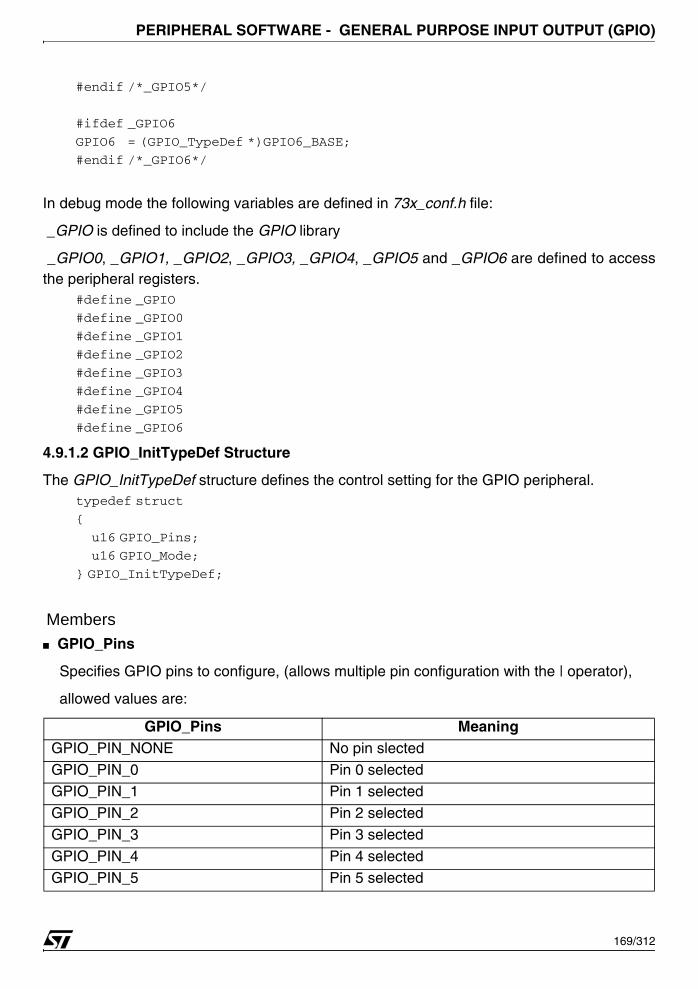
PERIPHERAL SOFTWARE - GENERAL PURPOSE INPUT OUTPUT (GPIO)
#endif /*_GPIO5*/
#ifdef _GPIO6
GPIO6 = (GPIO_TypeDef *)GPIO6_BASE;
#endif /*_GPIO6*/
In debug mode the following variables are defined in 73x_conf.h file:
_GPIO is defined to include the GPIO library
_GPIO0, _GPIO1, _GPIO2, _GPIO3, _GPIO4, _GPIO5 and _GPIO6 are defined to accessthe peripheral registers.
#define _GPIO
#define _GPIO0
#define _GPIO1
#define _GPIO2
#define _GPIO3
#define _GPIO4
#define _GPIO5
#define _GPIO6
4.9.1.2 GPIO_InitTypeDef Structure
The GPIO_InitTypeDef structure defines the control setting for the GPIO peripheral.typedef struct
{
u16 GPIO_Pins;
u16 GPIO_Mode;
} GPIO_InitTypeDef;
Members■ GPIO_Pins
Specifies GPIO pins to configure, (allows multiple pin configuration with the | operator),
allowed values are:
GPIO_Pins MeaningGPIO_PIN_NONE No pin slected
GPIO_PIN_0 Pin 0 selectedGPIO_PIN_1 Pin 1 selected
GPIO_PIN_2 Pin 2 selected
GPIO_PIN_3 Pin 3 selected
GPIO_PIN_4 Pin 4 selected
GPIO_PIN_5 Pin 5 selected
169/312
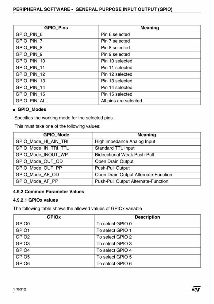
PERIPHERAL SOFTWARE - GENERAL PURPOSE INPUT OUTPUT (GPIO)
■ GPIO_Modes
Specifies the working mode for the selected pins.
This must take one of the following values:
4.9.2 Common Parameter Values
4.9.2.1 GPIOx values
The following table shows the allowed values of GPIOx variable
GPIO_PIN_6 Pin 6 selectedGPIO_PIN_7 Pin 7 selected
GPIO_PIN_8 Pin 8 selected
GPIO_PIN_9 Pin 9 selected
GPIO_PIN_10 Pin 10 selected
GPIO_PIN_11 Pin 11 selected
GPIO_PIN_12 Pin 12 selectedGPIO_PIN_13 Pin 13 selected
GPIO_PIN_14 Pin 14 selected
GPIO_PIN_15 Pin 15 selected
GPIO_PIN_ALL All pins are selected
GPIO_Mode MeaningGPIO_Mode_HI_AIN_TRI High impedance Analog Input
GPIO_Mode_IN_TRI_TTL Standard TTL Input
GPIO_Mode_INOUT_WP Bidirectional Weak Push-Pull
GPIO_Mode_OUT_OD Open Drain Output
GPIO_Mode_OUT_PP Push-Pull OutputGPIO_Mode_AF_OD Open Drain Output Alternate-Function
GPIO_Mode_AF_PP Push-Pull Output Alternate-Function
GPIOx DescriptionGPIO0 To select GPIO 0GPIO1 To select GPIO 1
GPIO2 To select GPIO 2
GPIO3 To select GPIO 3
GPIO4 To select GPIO 4
GPIO5 To select GPIO 5
GPIO6 To select GPIO 6
GPIO_Pins Meaning
170/312
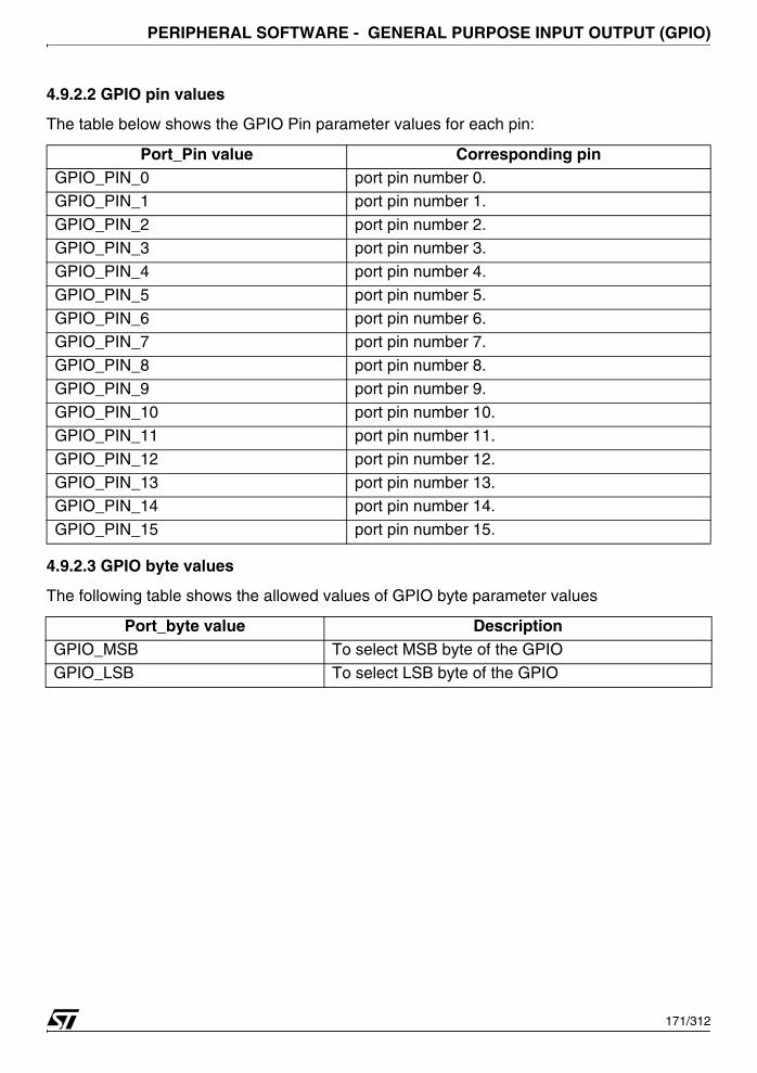
PERIPHERAL SOFTWARE - GENERAL PURPOSE INPUT OUTPUT (GPIO)
4.9.2.2 GPIO pin values
The table below shows the GPIO Pin parameter values for each pin:
4.9.2.3 GPIO byte values
The following table shows the allowed values of GPIO byte parameter values
Port_Pin value Corresponding pinGPIO_PIN_0 port pin number 0.GPIO_PIN_1 port pin number 1.
GPIO_PIN_2 port pin number 2.
GPIO_PIN_3 port pin number 3.
GPIO_PIN_4 port pin number 4.
GPIO_PIN_5 port pin number 5.
GPIO_PIN_6 port pin number 6.GPIO_PIN_7 port pin number 7.
GPIO_PIN_8 port pin number 8.
GPIO_PIN_9 port pin number 9.
GPIO_PIN_10 port pin number 10.
GPIO_PIN_11 port pin number 11.
GPIO_PIN_12 port pin number 12.
GPIO_PIN_13 port pin number 13.GPIO_PIN_14 port pin number 14.
GPIO_PIN_15 port pin number 15.
Port_byte value DescriptionGPIO_MSB To select MSB byte of the GPIO
GPIO_LSB To select LSB byte of the GPIO
171/312
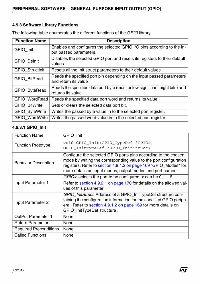
PERIPHERAL SOFTWARE - GENERAL PURPOSE INPUT OUTPUT (GPIO)
4.9.3 Software Library Functions
The following table enumerates the different functions of the GPIO library.
4.9.3.1 GPIO_Init
Function Name Description
GPIO_InitEnables and configures the selected GPIO I/O pins according to the in-put passed parameters.
GPIO_DeInitDisables the selected GPIO port and resets its registers to their default values
GPIO_StructInit Resets all the Init struct parameters to their default values
GPIO_BitReadReads the specified port pin depending on the input passed parameters and return its value
GPIO_ByteReadReads the specified data port byte (most or low significant eight bits) and returns its value.
GPIO_WordRead Reads the specified data port word and returns its value.GPIO_BitWrite Sets or clears the selected data port bit.
GPIO_ByteWrite Writes the passed byte value in to the selected port register.
GPIO_WordWrite Writes the passed word value in to the selected port register.
Function Name GPIO_Init
Function Prototypevoid GPIO_Init(GPIO_TypeDef *GPIOx, GPIO_InitTypeDef *GPIO_InitStruct)
Behavior Description
Configure the selected GPIO ports pins according to the chosen mode by writing the corresponding value to the port configuration registers. Refer to section 4.9.1.2 on page 169 "GPIO_Modes" for more details on input modes, output modes and port names.
Input Parameter 1GPIOx: selects the port to be configured. x can be 0,1,...6.
Refer to section 4.9.2.1 on page 170 for details on the allowed val-ues of this parameter.
Input Parameter 2
GPIO_InitStruct: Address of a GPIO_InitTypeDef structure con-taining the configuration information for the specified GPIO periph-eral. Refer to section 4.9.1.2 on page 169 for more details on GPIO_InitTypeDef structure .
OutPut Parameter 1 None
Return Parameter NoneRequired Preconditions None
Called Functions None
172/312
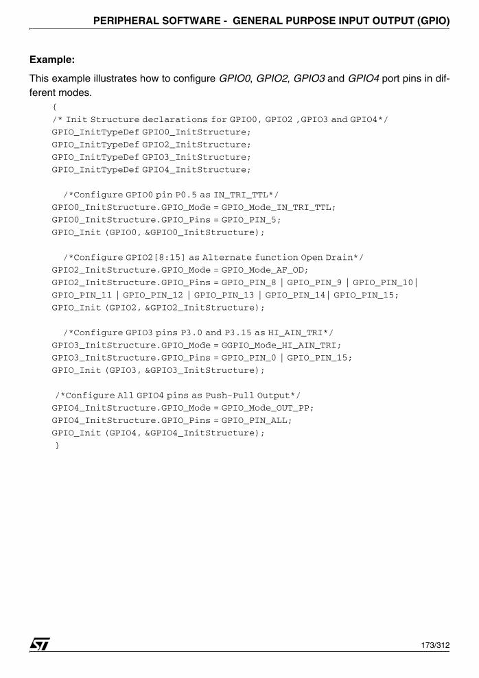
PERIPHERAL SOFTWARE - GENERAL PURPOSE INPUT OUTPUT (GPIO)
Example:
This example illustrates how to configure GPIO0, GPIO2, GPIO3 and GPIO4 port pins in dif-ferent modes.
{
/* Init Structure declarations for GPIO0, GPIO2 ,GPIO3 and GPIO4*/
GPIO_InitTypeDef GPIO0_InitStructure;
GPIO_InitTypeDef GPIO2_InitStructure;
GPIO_InitTypeDef GPIO3_InitStructure;
GPIO_InitTypeDef GPIO4_InitStructure;
/*Configure GPIO0 pin P0.5 as IN_TRI_TTL*/
GPIO0_InitStructure.GPIO_Mode = GPIO_Mode_IN_TRI_TTL;
GPIO0_InitStructure.GPIO_Pins = GPIO_PIN_5;
GPIO_Init (GPIO0, &GPIO0_InitStructure);
/*Configure GPIO2[8:15] as Alternate function Open Drain*/
GPIO2_InitStructure.GPIO_Mode = GPIO_Mode_AF_OD;
GPIO2_InitStructure.GPIO_Pins = GPIO_PIN_8 | GPIO_PIN_9 | GPIO_PIN_10|
GPIO_PIN_11 | GPIO_PIN_12 | GPIO_PIN_13 | GPIO_PIN_14| GPIO_PIN_15;
GPIO_Init (GPIO2, &GPIO2_InitStructure);
/*Configure GPIO3 pins P3.0 and P3.15 as HI_AIN_TRI*/
GPIO3_InitStructure.GPIO_Mode = GGPIO_Mode_HI_AIN_TRI;
GPIO3_InitStructure.GPIO_Pins = GPIO_PIN_0 | GPIO_PIN_15;
GPIO_Init (GPIO3, &GPIO3_InitStructure);
/*Configure All GPIO4 pins as Push-Pull Output*/
GPIO4_InitStructure.GPIO_Mode = GPIO_Mode_OUT_PP;
GPIO4_InitStructure.GPIO_Pins = GPIO_PIN_ALL;
GPIO_Init (GPIO4, &GPIO4_InitStructure);
}
173/312

PERIPHERAL SOFTWARE - GENERAL PURPOSE INPUT OUTPUT (GPIO)
4.9.3.2 GPIO_DeInit
Example:
This example illustrates how to deinitialize GPIO0, GPIO2 port pins.{
/*Deinitialize GPIO0 and GPIO2 ports registers*/
GPIO_DeInit (GPIO0);
GPIO_DeInit (GPIO2);
}
4.9.3.3 GPIO_StructInit
Example:
This example illustrates how to initialize GPIO0, GPIO2 port pins init structure.{
GPIO_InitTypeDef GPIO0_InitStructure;
GPIO_InitTypeDef GPIO2_InitStructure;
GPIO_StructInit (&GPIO0_InitStructure);
GPIO_StructInit (&GPIO2_InitStructure);
}
Function Name GPIO_DeInit
Function Prototype void GPIO_DeInit (GPIO_TypeDef *GPIOx)
Behavior Description Reset all the GPIOx registers to their default values
Input Parameter 1GPIOx: this parameter specifies the port. x can be 0,1,..6.
Refer to section 4.9.2.1 on page 170 for details on the allowed val-ues of this parameter.
OutPut Parameter None
Return Parameter NoneRequired Preconditions None
Called Functions None
Function Name GPIO_StructInit
Function Prototypevoid GPIO_StructInit(GPIO_InitTypeDef *GPIO_InitStruct)
Behavior Description Resets all the Init struct parameters to their default values
Input Parameter GPIO_InitStruct: Address of a GPIO_InitTypeDef structure.OutPut Parameter None
Return Parameter None
Required Preconditions None
Called Functions None
174/312
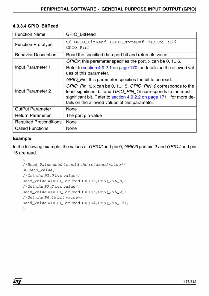
PERIPHERAL SOFTWARE - GENERAL PURPOSE INPUT OUTPUT (GPIO)
4.9.3.4 GPIO_BitRead
Example:
In the following example, the values of GPIO2 port pin 0, GPIO3 port pin 2 and GPIO4 port pin15 are read.
{
/*Read_Value used to hold the returned value*/
u8 Read_Value;
/*Get the P2.0 bit value*/
Read_Value = GPIO_BitRead (GPIO2,GPIO_PIN_0);
/*Get the P3.2 bit value*/
Read_Value = GPIO_BitRead (GPIO3,GPIO_PIN_2);
/*Get the P4.15 bit value*/
Read_Value = GPIO_BitRead (GPIO4,GPIO_PIN_15);
}
Function Name GPIO_BitRead
Function Prototypeu8 GPIO_BitRead (GPIO_TypeDef *GPIOx, u16 GPIO_Pin)
Behavior Description Read the specified data port bit and return its value.
Input Parameter 1GPIOx: this parameter specifies the port. x can be 0, 1...6.
Refer to section 4.9.2.1 on page 170 for details on the allowed val-ues of this parameter.
Input Parameter 2
GPIO_Pin: this parameter specifies the bit to be read.
GPIO_Pin_x. x can be 0, 1...15. GPIO_PIN_0 corresponds to the least significant bit and GPIO_PIN_15 corresponds to the most significant bit. Refer to section 4.9.2.2 on page 171 for more de-tails on the allowed values of this parameter.
OutPut Parameter None
Return Parameter The port pin value
Required Preconditions None
Called Functions None
175/312
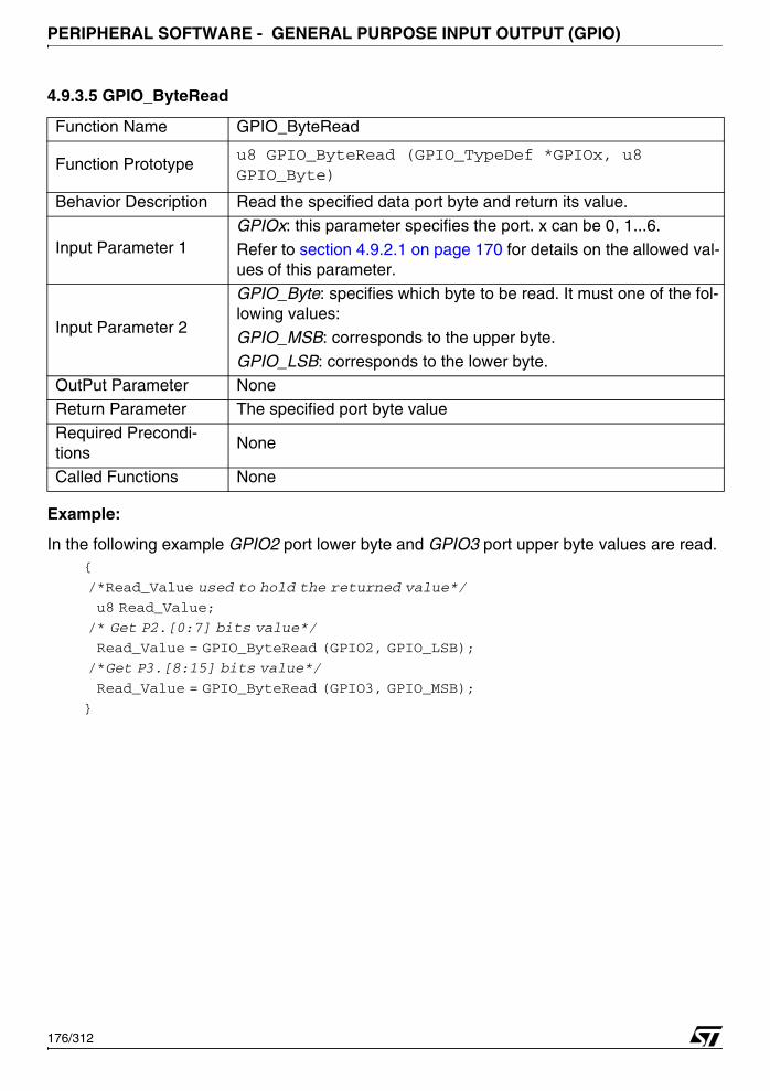
PERIPHERAL SOFTWARE - GENERAL PURPOSE INPUT OUTPUT (GPIO)
4.9.3.5 GPIO_ByteRead
Example:
In the following example GPIO2 port lower byte and GPIO3 port upper byte values are read.{
/*Read_Value used to hold the returned value*/
u8 Read_Value;
/* Get P2.[0:7] bits value*/
Read_Value = GPIO_ByteRead (GPIO2, GPIO_LSB);
/*Get P3.[8:15] bits value*/
Read_Value = GPIO_ByteRead (GPIO3, GPIO_MSB);
}
Function Name GPIO_ByteRead
Function Prototypeu8 GPIO_ByteRead (GPIO_TypeDef *GPIOx, u8 GPIO_Byte)
Behavior Description Read the specified data port byte and return its value.
Input Parameter 1GPIOx: this parameter specifies the port. x can be 0, 1...6.
Refer to section 4.9.2.1 on page 170 for details on the allowed val-ues of this parameter.
Input Parameter 2
GPIO_Byte: specifies which byte to be read. It must one of the fol-lowing values:
GPIO_MSB: corresponds to the upper byte.
GPIO_LSB: corresponds to the lower byte.
OutPut Parameter NoneReturn Parameter The specified port byte value
Required Precondi-tions
None
Called Functions None
176/312

PERIPHERAL SOFTWARE - GENERAL PURPOSE INPUT OUTPUT (GPIO)
4.9.3.6 GPIO_WordRead
Example:
The following example illustrates how to read GPIO4 port pin values.{
/* Read_Value used to hold the returned value*/
u16 Read_Value;
/*Get all GPIO4 pins value*/
Read_Value = GPIO_WordRead (GPIO4);
}
Function Name GPIO_WordRead
Function Prototype u16 GPIO_WordRead (GPIO_TypeDef *GPIOx)
Behavior Description Return the value of the specified data port register GPIOx.PD
Input Parameter 1 GPIOx: this parameter specifies the port. x can be 0, 1...6.
Refer to section 4.9.2.1 on page 170 for more details on the al-lowed values of this parameter.
OutPut Parameter None
Return Parameter The specified port word valueRequired Preconditions None
Called Functions None
177/312
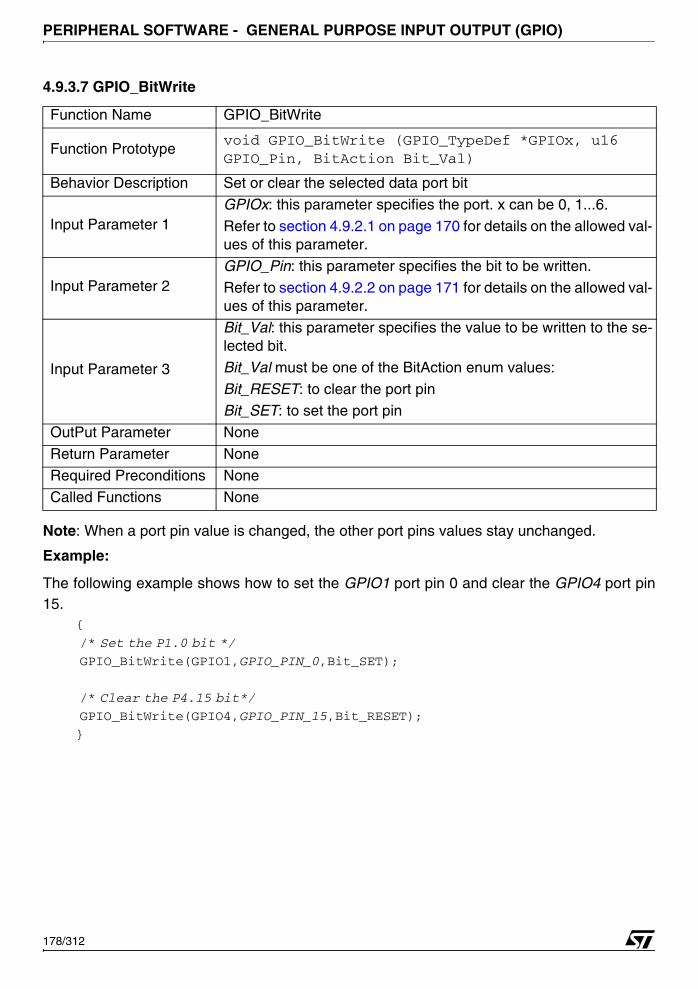
PERIPHERAL SOFTWARE - GENERAL PURPOSE INPUT OUTPUT (GPIO)
4.9.3.7 GPIO_BitWrite
Note: When a port pin value is changed, the other port pins values stay unchanged.
Example:
The following example shows how to set the GPIO1 port pin 0 and clear the GPIO4 port pin15.
{
/* Set the P1.0 bit */
GPIO_BitWrite(GPIO1,GPIO_PIN_0,Bit_SET);
/* Clear the P4.15 bit*/
GPIO_BitWrite(GPIO4,GPIO_PIN_15,Bit_RESET);
}
Function Name GPIO_BitWrite
Function Prototypevoid GPIO_BitWrite (GPIO_TypeDef *GPIOx, u16 GPIO_Pin, BitAction Bit_Val)
Behavior Description Set or clear the selected data port bit
Input Parameter 1 GPIOx: this parameter specifies the port. x can be 0, 1...6.
Refer to section 4.9.2.1 on page 170 for details on the allowed val-ues of this parameter.
Input Parameter 2 GPIO_Pin: this parameter specifies the bit to be written.
Refer to section 4.9.2.2 on page 171 for details on the allowed val-ues of this parameter.
Input Parameter 3
Bit_Val: this parameter specifies the value to be written to the se-lected bit.
Bit_Val must be one of the BitAction enum values:
Bit_RESET: to clear the port pinBit_SET: to set the port pin
OutPut Parameter None
Return Parameter None
Required Preconditions None
Called Functions None
178/312

PERIPHERAL SOFTWARE - GENERAL PURPOSE INPUT OUTPUT (GPIO)
4.9.3.8 GPIO_ByteWrite
Note: When a port byte value is changed, the other port byte value stay unchanged.
Example:
The following example shows how to set all the GPIO2[0:7] port pins and clear all theGPIO3[8:15] port pins. the GPIO2[8:15] and GPIO3[0:7] remain unchanged.
{
/*Set all the GPIO2[0:7] port pins*/
GPIO_ByteWrite(GPIO2,GPIO_LSB,0xFF);
/* Clear all the GPIO3[8:15] port pins*/
GPIO_ByteWrite(GPIO3,GPIO_MSB,0x00);
}
Function Name GPIO_ByteWrite
Function Prototypevoid GPIO_ByteWrite (GPIO_TypeDef *GPIOx, u8 GPIO_Byte, u8 Byte_Val)
Behavior Description write the passed value in to the selected GPIOx byte
Input Parameter 1 GPIOx: this parameter specifies the port. x can be 0, 1...6.
Input Parameter 2
GPIO_Byte: specifies the write on which byte. It must be either GPIO_MSB or GPIO_LSB
GPIO_MSB corresponds to the upper byte.
GPIO_LSB corresponds to the lower byte.
Input Parameter 3 Byte_Val: The value to be written to the selected byteOutPut Parameter None
Return Parameter None
Required Preconditions None
Called Functions None
179/312
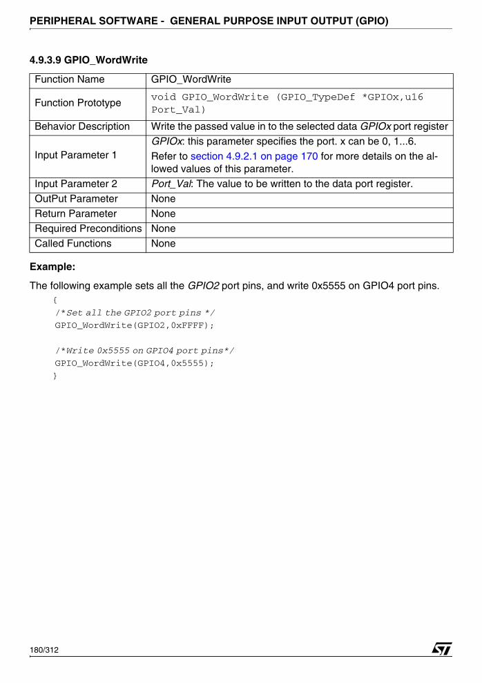
PERIPHERAL SOFTWARE - GENERAL PURPOSE INPUT OUTPUT (GPIO)
4.9.3.9 GPIO_WordWrite
Example:
The following example sets all the GPIO2 port pins, and write 0x5555 on GPIO4 port pins.{
/*Set all the GPIO2 port pins */
GPIO_WordWrite(GPIO2,0xFFFF);
/*Write 0x5555 on GPIO4 port pins*/
GPIO_WordWrite(GPIO4,0x5555);
}
Function Name GPIO_WordWrite
Function Prototypevoid GPIO_WordWrite (GPIO_TypeDef *GPIOx,u16 Port_Val)
Behavior Description Write the passed value in to the selected data GPIOx port register
Input Parameter 1 GPIOx: this parameter specifies the port. x can be 0, 1...6.
Refer to section 4.9.2.1 on page 170 for more details on the al-lowed values of this parameter.
Input Parameter 2 Port_Val: The value to be written to the data port register.
OutPut Parameter None
Return Parameter NoneRequired Preconditions None
Called Functions None
180/312
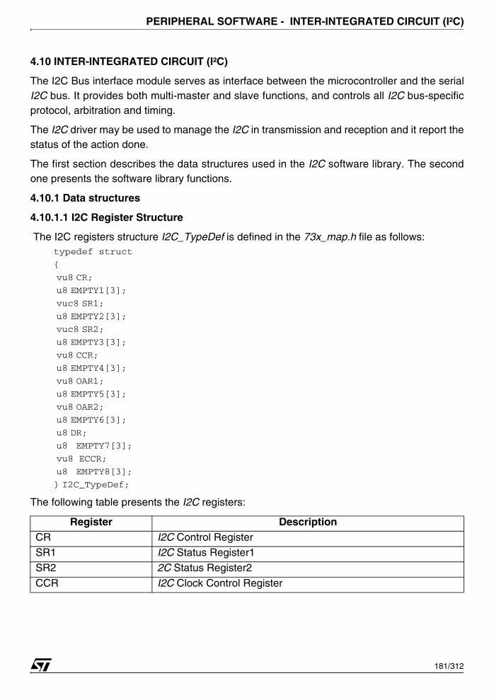
PERIPHERAL SOFTWARE - INTER-INTEGRATED CIRCUIT (I²C)
4.10 INTER-INTEGRATED CIRCUIT (I²C)
The I2C Bus interface module serves as interface between the microcontroller and the serialI2C bus. It provides both multi-master and slave functions, and controls all I2C bus-specificprotocol, arbitration and timing.
The I2C driver may be used to manage the I2C in transmission and reception and it report thestatus of the action done.
The first section describes the data structures used in the I2C software library. The secondone presents the software library functions.
4.10.1 Data structures
4.10.1.1 I2C Register Structure
The I2C registers structure I2C_TypeDef is defined in the 73x_map.h file as follows:typedef struct
{
vu8 CR;
u8 EMPTY1[3];
vuc8 SR1;
u8 EMPTY2[3];
vuc8 SR2;
u8 EMPTY3[3];
vu8 CCR;
u8 EMPTY4[3];
vu8 OAR1;
u8 EMPTY5[3];
vu8 OAR2;
u8 EMPTY6[3];
u8 DR;
u8 EMPTY7[3];
vu8 ECCR;
u8 EMPTY8[3];
} I2C_TypeDef;
The following table presents the I2C registers:
Register DescriptionCR I2C Control Register
SR1 I2C Status Register1
SR2 2C Status Register2
CCR I2C Clock Control Register
181/312
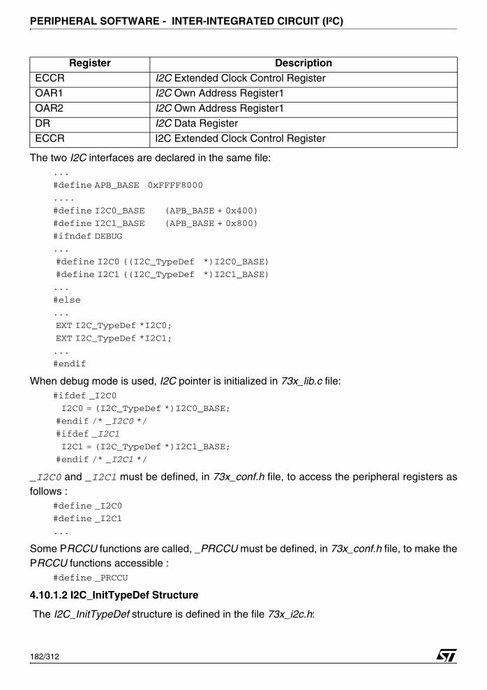
PERIPHERAL SOFTWARE - INTER-INTEGRATED CIRCUIT (I²C)
The two I2C interfaces are declared in the same file:...
#define APB_BASE 0xFFFF8000
....
#define I2C0_BASE (APB_BASE + 0x400)
#define I2C1_BASE (APB_BASE + 0x800)
#ifndef DEBUG
...
#define I2C0 ((I2C_TypeDef *)I2C0_BASE)
#define I2C1 ((I2C_TypeDef *)I2C1_BASE)
...
#else
...
EXT I2C_TypeDef *I2C0;
EXT I2C_TypeDef *I2C1;
...
#endif
When debug mode is used, I2C pointer is initialized in 73x_lib.c file:#ifdef _I2C0
I2C0 = (I2C_TypeDef *)I2C0_BASE;
#endif /* _I2C0 */
#ifdef _I2C1
I2C1 = (I2C_TypeDef *)I2C1_BASE;
#endif /* _I2C1 */
_I2C0 and _I2C1 must be defined, in 73x_conf.h file, to access the peripheral registers asfollows :
#define _I2C0
#define _I2C1
...
Some PRCCU functions are called, _PRCCU must be defined, in 73x_conf.h file, to make thePRCCU functions accessible :
#define _PRCCU
4.10.1.2 I2C_InitTypeDef Structure
The I2C_InitTypeDef structure is defined in the file 73x_i2c.h:
ECCR I2C Extended Clock Control RegisterOAR1 I2C Own Address Register1
OAR2 I2C Own Address Register1
DR I2C Data Register
ECCR I2C Extended Clock Control Register
Register Description
182/312
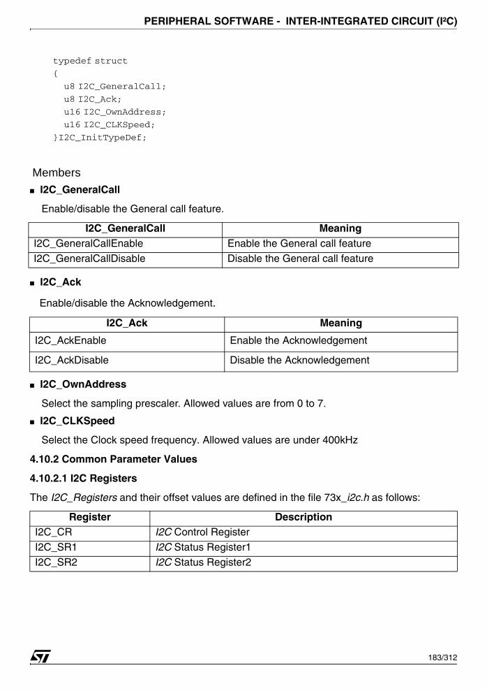
PERIPHERAL SOFTWARE - INTER-INTEGRATED CIRCUIT (I²C)
typedef struct
{
u8 I2C_GeneralCall;
u8 I2C_Ack;
u16 I2C_OwnAddress;
u16 I2C_CLKSpeed;
}I2C_InitTypeDef;
Members■ I2C_GeneralCall
Enable/disable the General call feature.
■ I2C_Ack
Enable/disable the Acknowledgement.
■ I2C_OwnAddress
Select the sampling prescaler. Allowed values are from 0 to 7.
■ I2C_CLKSpeed
Select the Clock speed frequency. Allowed values are under 400kHz
4.10.2 Common Parameter Values
4.10.2.1 I2C Registers
The I2C_Registers and their offset values are defined in the file 73x_i2c.h as follows:
I2C_GeneralCall MeaningI2C_GeneralCallEnable Enable the General call feature
I2C_GeneralCallDisable Disable the General call feature
I2C_Ack Meaning
I2C_AckEnable Enable the Acknowledgement
I2C_AckDisable Disable the Acknowledgement
Register DescriptionI2C_CR I2C Control Register
I2C_SR1 I2C Status Register1
I2C_SR2 I2C Status Register2
183/312
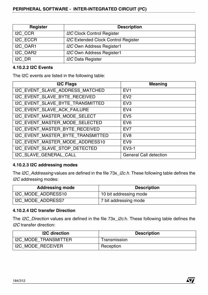
PERIPHERAL SOFTWARE - INTER-INTEGRATED CIRCUIT (I²C)
4.10.2.2 I2C Events
The I2C events are listed in the following table:
4.10.2.3 I2C addressing modes
The I2C_Addressing values are defined in the file 73x_i2c.h. These following table defines theI2C addressing modes:
4.10.2.4 I2C transfer Direction
The I2C_Direction values are defined in the file 73x_i2c.h. These following table defines theI2C transfer direction:
I2C_CCR I2C Clock Control RegisterI2C_ECCR I2C Extended Clock Control Register
I2C_OAR1 I2C Own Address Register1
I2C_OAR2 I2C Own Address Register1
I2C_DR I2C Data Register
I2C Flags MeaningI2C_EVENT_SLAVE_ADDRESS_MATCHED EV1
I2C_EVENT_SLAVE_BYTE_RECEIVED EV2
I2C_EVENT_SLAVE_BYTE_TRANSMITTED EV3
I2C_EVENT_SLAVE_ACK_FAILURE EV4
I2C_EVENT_MASTER_MODE_SELECT EV5
I2C_EVENT_MASTER_MODE_SELECTED EV6
I2C_EVENT_MASTER_BYTE_RECEIVED EV7I2C_EVENT_MASTER_BYTE_TRANSMITTED EV8
I2C_EVENT_MASTER_MODE_ADDRESS10 EV9
I2C_EVENT_SLAVE_STOP_DETECTED EV3-1
I2C_SLAVE_GENERAL_CALL General Call detection
Addressing mode DescriptionI2C_MODE_ADDRESS10 10 bit addressing mode
I2C_MODE_ADDRESS7 7 bit addressing mode
I2C direction DescriptionI2C_MODE_TRANSMITTER TransmissionI2C_MODE_RECEIVER Reception
Register Description
184/312
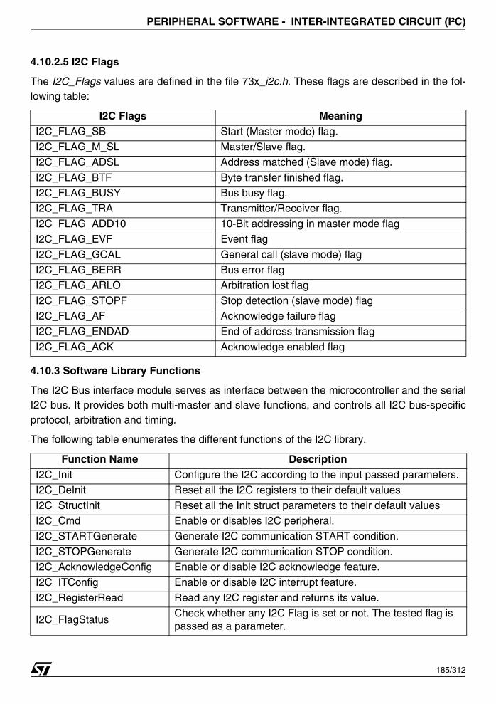
PERIPHERAL SOFTWARE - INTER-INTEGRATED CIRCUIT (I²C)
4.10.2.5 I2C Flags
The I2C_Flags values are defined in the file 73x_i2c.h. These flags are described in the fol-lowing table:
4.10.3 Software Library Functions
The I2C Bus interface module serves as interface between the microcontroller and the serialI2C bus. It provides both multi-master and slave functions, and controls all I2C bus-specificprotocol, arbitration and timing.
The following table enumerates the different functions of the I2C library.
I2C Flags MeaningI2C_FLAG_SB Start (Master mode) flag.
I2C_FLAG_M_SL Master/Slave flag.
I2C_FLAG_ADSL Address matched (Slave mode) flag.
I2C_FLAG_BTF Byte transfer finished flag.I2C_FLAG_BUSY Bus busy flag.
I2C_FLAG_TRA Transmitter/Receiver flag.
I2C_FLAG_ADD10 10-Bit addressing in master mode flag
I2C_FLAG_EVF Event flag
I2C_FLAG_GCAL General call (slave mode) flag
I2C_FLAG_BERR Bus error flagI2C_FLAG_ARLO Arbitration lost flag
I2C_FLAG_STOPF Stop detection (slave mode) flag
I2C_FLAG_AF Acknowledge failure flag
I2C_FLAG_ENDAD End of address transmission flag
I2C_FLAG_ACK Acknowledge enabled flag
Function Name DescriptionI2C_Init Configure the I2C according to the input passed parameters.
I2C_DeInit Reset all the I2C registers to their default values
I2C_StructInit Reset all the Init struct parameters to their default valuesI2C_Cmd Enable or disables I2C peripheral.
I2C_STARTGenerate Generate I2C communication START condition.
I2C_STOPGenerate Generate I2C communication STOP condition.
I2C_AcknowledgeConfig Enable or disable I2C acknowledge feature.
I2C_ITConfig Enable or disable I2C interrupt feature.
I2C_RegisterRead Read any I2C register and returns its value.
I2C_FlagStatusCheck whether any I2C Flag is set or not. The tested flag is passed as a parameter.
185/312

PERIPHERAL SOFTWARE - INTER-INTEGRATED CIRCUIT (I²C)
4.10.3.1 I2C_Init
I2C_FlagClearClears any I2C Flag. The concerning flag is passed as a pa-rameter.
I2C_AddressSend Transmits the address byte to select the slave device.I2C_ByteSend Transmits single byte of data.
I2C_BufferSendTransmits data from a buffer whose number of bytes is known. Data transmission will stop if any error occurs during transmis-sion. The transmission status will be returned to the user.
I2C_ByteReceive Returns the most recent received byte.
I2C_BufferReceiveReceives a number of data bytes and stores them in user de-fined area. The data reception will stop, if any error occurs dur-ing reception. The reception status will be returned to the user.
I2C_GetStatusGet the I2Cx flags status in a 16 bit register: ACK, ENDAD, AF, STOPF, ARLO, BERR, GCAL, EVF, ADD10, TRA, BUSY, BTF, ADSL, M/SL, SB.
I2C_GetLastEventGet the I2Cx flags status in a 16 bit register: ENDAD, AF, STOPF, ARLO, BERR, GCAL, EVF, ADD10, TRA, BUSY, BTF, ADSL, M/SL, SB.
I2C_EventCheckCheck if the last occurred event is equal to the one passed as parameter.
Function Name I2C_Init
Function Prototypevoid I2C_Init (I2C_TypeDef *I2Cx, I2C_InitTypeDef *I2C_InitStruct)
Behavior Description Configure the selected I2C according to the chosen mode by writing the corresponding value to the I2C registers.
Input Parameter 1 I2Cx: selects the I2C to be configured. x can be 0 or 1.
Input Parameter 2I2C_InitStruct: An I2C_InitTypeDef structure containing the con-figuration information for the I2C peripheral. For more details re-fer to section 4.10.1.2 on page 182.
OutPut Parameter None
Return Parameter None
Required Preconditions None
Called Functions None
Function Name Description
186/312
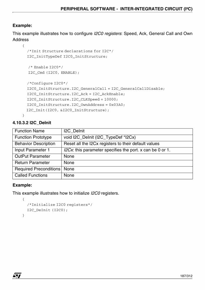
PERIPHERAL SOFTWARE - INTER-INTEGRATED CIRCUIT (I²C)
Example:
This example illustrates how to configure I2C0 registers: Speed, Ack, General Call and OwnAddress
{
/*Init Structure declarations for I2C*/
I2C_InitTypeDef I2C0_InitStructure;
/* Enable I2C0*/
I2C_Cmd (I2C0, ENABLE);
/*Configure I2C0*/
I2C0_InitStructure.I2C_GeneralCall = I2C_GeneralCallDisable;
I2C0_InitStructure.I2C_Ack = I2C_AckEnable;
I2C0_InitStructure.I2C_CLKSpeed = 10000;
I2C0_InitStructure.I2C_OwnAddress = 0x03A0;
I2C_Init(I2C0, &I2C0_InitStructure); }
4.10.3.2 I2C_DeInit
Example:
This example illustrates how to initialize I2C0 registers.{
/*Initialize I2C0 registers*/
I2C_DeInit (I2C0);
}
Function Name I2C_DeInit
Function Prototype void I2C_DeInit (I2C_TypeDef *I2Cx)
Behavior Description Reset all the I2Cx registers to their default values
Input Parameter 1 I2Cx: this parameter specifies the port. x can be 0 or 1.
OutPut Parameter None
Return Parameter NoneRequired Preconditions None
Called Functions None
187/312

PERIPHERAL SOFTWARE - INTER-INTEGRATED CIRCUIT (I²C)
4.10.3.3 I2C_StructInit
Example:
This example illustrates how to initialize I2C0 init structure.{
/*Init Structures declarations for I2C0 */
I2C_InitTypeDef I2C0_InitStructure;
/*Initialize I2C0 Init structure*/
I2C_StructInit (&I2C0_InitStructure);
}
4.10.3.4 I2C_Cmd
Function Name I2C_StructInit
Function Prototypevoid I2C_StructInit(I2C_InitTypeDef *I2C_InitStruct)
Behavior Description Resets all the Init struct parameters to their default values
Input Parameter I2C_InitStruct: An I2C_InitTypeDef structure.
OutPut Parameter None
Return Parameter None
Required Preconditions NoneCalled Functions None
Function Name I2C_Cmd
Function Prototypevoid I2C_Cmd (I2C_TypeDef *I2Cx, FunctionalState NewState)
Description Enables or disables I2C peripheral.
Input Parameter 1 I2Cx: This parameter specifies the port. x can be 0 or 1.
Input Parameter 2NewState: specifies whether the I2C peripheral will be enabled.ENABLE: Enable I2C Peripheral.
DISABLE: Disable I2C Peripheral.
OutPut Parameter PE bit in I2CCR is modified according to NewState parameter.
Return Parameters None.
Required Preconditions I/O ports should be configured in their reset states.
Called Functions None.
188/312
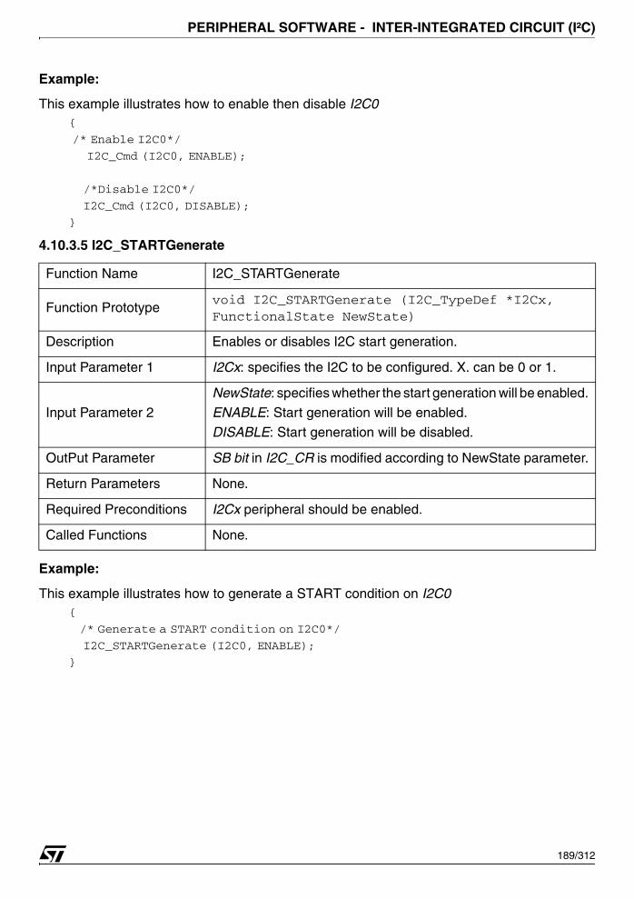
PERIPHERAL SOFTWARE - INTER-INTEGRATED CIRCUIT (I²C)
Example:
This example illustrates how to enable then disable I2C0 {
/* Enable I2C0*/
I2C_Cmd (I2C0, ENABLE);
/*Disable I2C0*/
I2C_Cmd (I2C0, DISABLE);
}
4.10.3.5 I2C_STARTGenerate
Example:
This example illustrates how to generate a START condition on I2C0 {
/* Generate a START condition on I2C0*/
I2C_STARTGenerate (I2C0, ENABLE);
}
Function Name I2C_STARTGenerate
Function Prototypevoid I2C_STARTGenerate (I2C_TypeDef *I2Cx, FunctionalState NewState)
Description Enables or disables I2C start generation.
Input Parameter 1 I2Cx: specifies the I2C to be configured. X. can be 0 or 1.
Input Parameter 2
NewState: specifies whether the start generation will be enabled.
ENABLE: Start generation will be enabled.
DISABLE: Start generation will be disabled.
OutPut Parameter SB bit in I2C_CR is modified according to NewState parameter.
Return Parameters None.
Required Preconditions I2Cx peripheral should be enabled.
Called Functions None.
189/312

PERIPHERAL SOFTWARE - INTER-INTEGRATED CIRCUIT (I²C)
4.10.3.6 I2C_STOPGenerate
Example:
This example illustrates how to generate a STOP condition on I2C0 {
/* Generate a STOP condition on I2C0*/
I2C_STOPGenerate (I2C0, ENABLE);
}
Function Name I2C_STOPGenerate
Function Prototypevoid I2C_STOPGenerate (I2C_TypeDef *I2Cx, FunctionalState NewState)
Description Enables or disables I2C stop generation.
Input Parameter 1 I2Cx: specifies the I2C to be configured. x can be 0 or 1.
Input Parameter 2
NewState: specifies whether the stop generation will be enabled or disabled.
ENABLE: Stop generation will be enabled.DISABLE: Stop generation will be disabled.
OutPut Parameter STOP bit in I2CCR is modified according to NewState parameter.
Return Parameters None.
Required Preconditions I2Cx peripheral should be enabled.
Called Functions None.
190/312
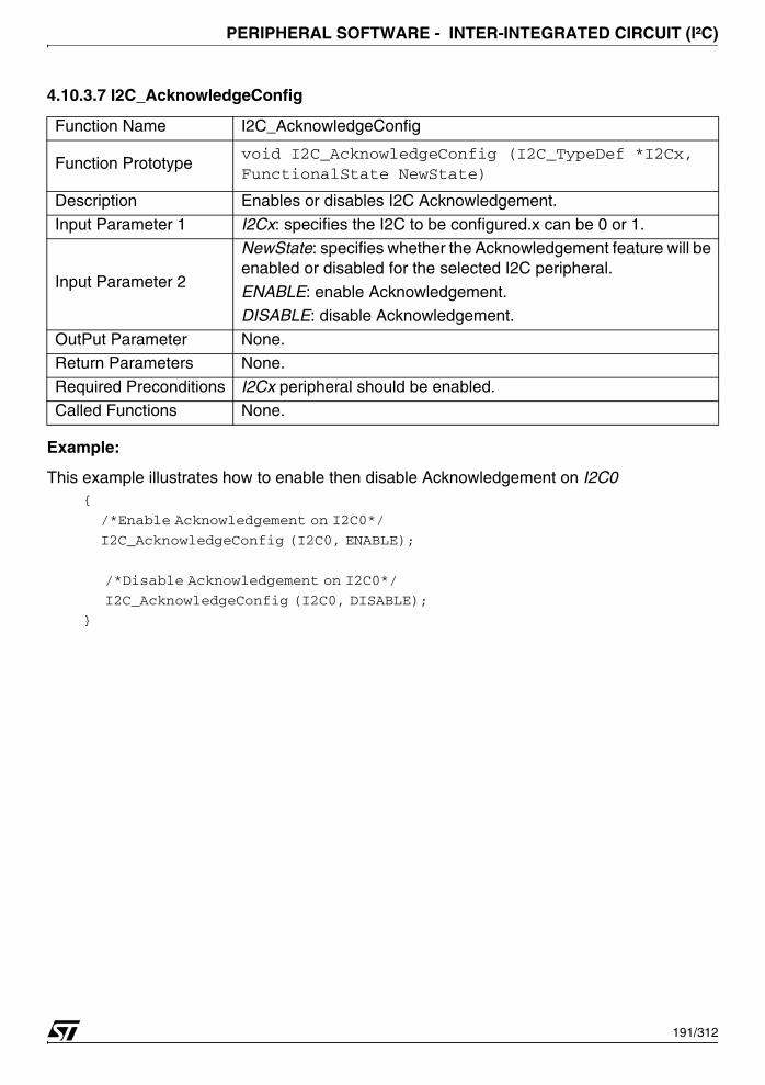
PERIPHERAL SOFTWARE - INTER-INTEGRATED CIRCUIT (I²C)
4.10.3.7 I2C_AcknowledgeConfig
Example:
This example illustrates how to enable then disable Acknowledgement on I2C0 {
/*Enable Acknowledgement on I2C0*/
I2C_AcknowledgeConfig (I2C0, ENABLE);
/*Disable Acknowledgement on I2C0*/
I2C_AcknowledgeConfig (I2C0, DISABLE);
}
Function Name I2C_AcknowledgeConfig
Function Prototypevoid I2C_AcknowledgeConfig (I2C_TypeDef *I2Cx, FunctionalState NewState)
Description Enables or disables I2C Acknowledgement.
Input Parameter 1 I2Cx: specifies the I2C to be configured.x can be 0 or 1.
Input Parameter 2
NewState: specifies whether the Acknowledgement feature will be enabled or disabled for the selected I2C peripheral.
ENABLE: enable Acknowledgement.
DISABLE: disable Acknowledgement.
OutPut Parameter None.Return Parameters None.
Required Preconditions I2Cx peripheral should be enabled.
Called Functions None.
191/312
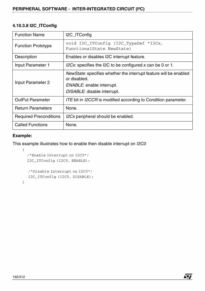
PERIPHERAL SOFTWARE - INTER-INTEGRATED CIRCUIT (I²C)
4.10.3.8 I2C_ITConfig
Example:
This example illustrates how to enable then disable interrupt on I2C0 {
/*Enable Interrupt on I2C0*/
I2C_ITConfig (I2C0, ENABLE);
/*Disable Interrupt on I2C0*/
I2C_ITConfig (I2C0, DISABLE);
}
Function Name I2C_ITConfig
Function Prototypevoid I2C_ITConfig (I2C_TypeDef *I2Cx, FunctionalState NewState)
Description Enables or disables I2C interrupt feature.
Input Parameter 1 I2Cx: specifies the I2C to be configured.x can be 0 or 1.
Input Parameter 2
NewState: specifies whether the interrupt feature will be enabled or disabled.
ENABLE: enable interrupt.DISABLE: disable interrupt.
OutPut Parameter ITE bit in I2CCR is modified according to Condition parameter.
Return Parameters None.
Required Preconditions I2Cx peripheral should be enabled.
Called Functions None.
192/312

PERIPHERAL SOFTWARE - INTER-INTEGRATED CIRCUIT (I²C)
4.10.3.9 I2C_RegisterRead
Example:
This example illustrates how to read the I2CCR register of I2C0 peripheral {
// Variable declaration
u8 Register_Value;
// Put the value of I2CCR register in Register_Value variable
Register_Value = I2C_RegisterRead(I2C0, I2C_CCR);
}
Function Name I2C_RegisterRead
Function Prototypeu8 I2C_RegisterRead (I2C_TypeDef *I2Cx, u8 I2C_Register)
Description Reads any register and returns its value.
Input Parameter 1 I2Cx: specifies the I2C to be configured. x can be 0 or 1.
Input Parameter 2I2C_Register: specifies the register to be read:
Refer to section 4.10.2.1 on page 183 for more details on the al-lowed values of this parameter.
OutPut Parameter The register to be read is accessed.
Return Parameters The value of the read register. It should be an ‘u8’ type.Required Preconditions None.
Called Functions None.
193/312
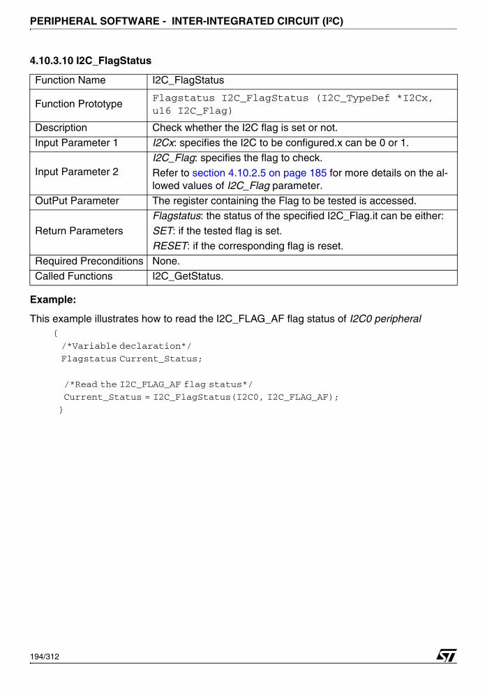
PERIPHERAL SOFTWARE - INTER-INTEGRATED CIRCUIT (I²C)
4.10.3.10 I2C_FlagStatus
Example:
This example illustrates how to read the I2C_FLAG_AF flag status of I2C0 peripheral {
/*Variable declaration*/
Flagstatus Current_Status;
/*Read the I2C_FLAG_AF flag status*/
Current_Status = I2C_FlagStatus(I2C0, I2C_FLAG_AF);
}
Function Name I2C_FlagStatus
Function PrototypeFlagstatus I2C_FlagStatus (I2C_TypeDef *I2Cx, u16 I2C_Flag)
Description Check whether the I2C flag is set or not.
Input Parameter 1 I2Cx: specifies the I2C to be configured.x can be 0 or 1.
Input Parameter 2I2C_Flag: specifies the flag to check.
Refer to section 4.10.2.5 on page 185 for more details on the al-lowed values of I2C_Flag parameter.
OutPut Parameter The register containing the Flag to be tested is accessed.
Return ParametersFlagstatus: the status of the specified I2C_Flag.it can be either:SET: if the tested flag is set.
RESET: if the corresponding flag is reset.
Required Preconditions None.
Called Functions I2C_GetStatus.
194/312
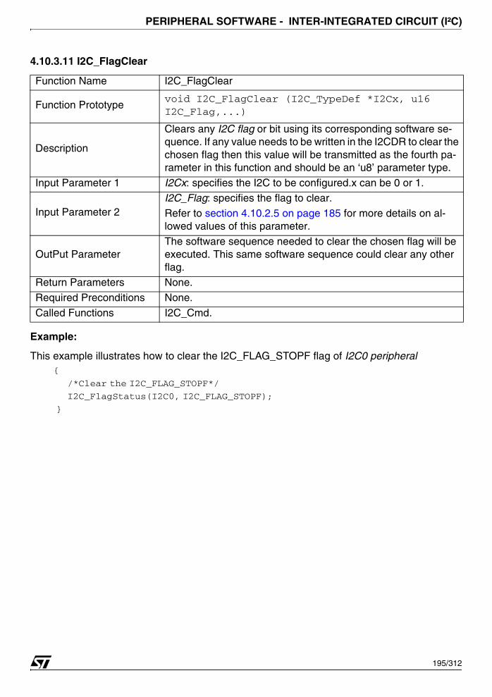
PERIPHERAL SOFTWARE - INTER-INTEGRATED CIRCUIT (I²C)
4.10.3.11 I2C_FlagClear
Example:
This example illustrates how to clear the I2C_FLAG_STOPF flag of I2C0 peripheral {
/*Clear the I2C_FLAG_STOPF*/
I2C_FlagStatus(I2C0, I2C_FLAG_STOPF);
}
Function Name I2C_FlagClear
Function Prototypevoid I2C_FlagClear (I2C_TypeDef *I2Cx, u16 I2C_Flag,...)
Description
Clears any I2C flag or bit using its corresponding software se-quence. If any value needs to be written in the I2CDR to clear the chosen flag then this value will be transmitted as the fourth pa-rameter in this function and should be an ‘u8’ parameter type.
Input Parameter 1 I2Cx: specifies the I2C to be configured.x can be 0 or 1.
Input Parameter 2I2C_Flag: specifies the flag to clear.
Refer to section 4.10.2.5 on page 185 for more details on al-lowed values of this parameter.
OutPut ParameterThe software sequence needed to clear the chosen flag will be executed. This same software sequence could clear any other flag.
Return Parameters None.
Required Preconditions None.
Called Functions I2C_Cmd.
195/312
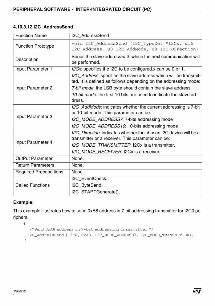
PERIPHERAL SOFTWARE - INTER-INTEGRATED CIRCUIT (I²C)
4.10.3.12 I2C_AddressSend
Example:
This example illustrates how to send 0xA8 address in 7-bit addressing transmitter for I2C0 pe-ripheral
{
/*Send 0xA8 address in 7-bit addressing transmitter */
I2C_AddressSend (I2C0, 0xA8, I2C_MODE_ADDRESS7, I2C_MODE_TRANSMITTER);
}
Function Name I2C_AddressSend
Function Prototypevoid I2C_AddressSend (I2C_TypeDef *I2Cx, u16 I2C_Address, u8 I2C_AddMode, u8 I2C_Direction)
DescriptionSends the slave address with which the next communication will be performed.
Input Parameter 1 I2Cx: specifies the I2C to be configured.x can be 0 or 1.
Input Parameter 2
I2C_Address: specifies the slave address which will be transmit-ted. It is defined as follows depending on the addressing mode:
7-bit mode: the LSB byte should contain the slave address.
10-bit mode: the first 10 bits are used to indicate the slave ad-dress.
Input Parameter 3
I2C_AddMode: indicates whether the current addressing is 7-bit or 10-bit mode. This parameter can be:
I2C_MODE_ADDRESS7: 7-bits addressing mode
I2C_MODE_ADDRESS10: 10-bits addressing mode
Input Parameter 4
I2C_Direction: indicates whether the chosen I2C device will be a transmitter or a receiver. This parameter can be:
I2C_MODE_TRANSMITTER: I2Cx is a transmitter.I2C_MODE_RECEIVER: I2Cx is a receiver.
OutPut Parameter None.
Return Parameters None.
Required Preconditions None.
Called Functions
I2C_EventCheck.
I2C_ByteSend.
I2C_STARTGenerate().
196/312
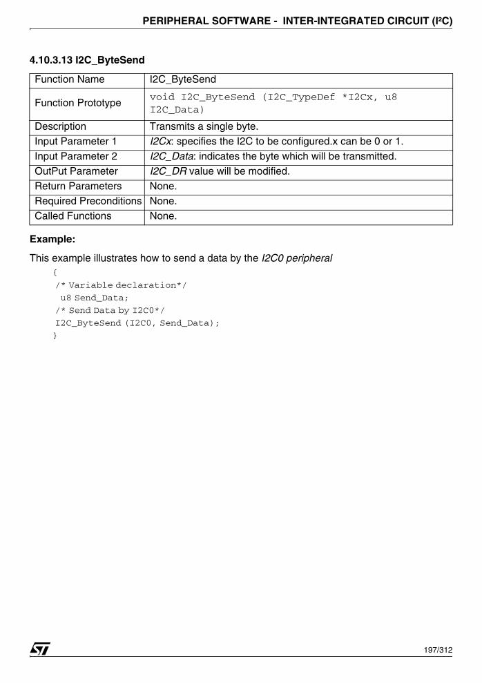
PERIPHERAL SOFTWARE - INTER-INTEGRATED CIRCUIT (I²C)
4.10.3.13 I2C_ByteSend
Example:
This example illustrates how to send a data by the I2C0 peripheral {
/* Variable declaration*/
u8 Send_Data;
/* Send Data by I2C0*/
I2C_ByteSend (I2C0, Send_Data);
}
Function Name I2C_ByteSend
Function Prototypevoid I2C_ByteSend (I2C_TypeDef *I2Cx, u8 I2C_Data)
Description Transmits a single byte.
Input Parameter 1 I2Cx: specifies the I2C to be configured.x can be 0 or 1.
Input Parameter 2 I2C_Data: indicates the byte which will be transmitted.
OutPut Parameter I2C_DR value will be modified.
Return Parameters None.Required Preconditions None.
Called Functions None.
197/312
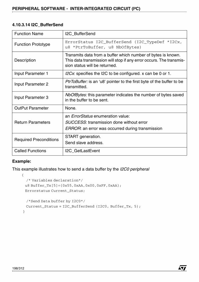
PERIPHERAL SOFTWARE - INTER-INTEGRATED CIRCUIT (I²C)
4.10.3.14 I2C_BufferSend
Example:
This example illustrates how to send a data buffer by the I2C0 peripheral {
/* Variables declaration*/
u8 Buffer_Tx[5]={0x55,0xAA,0x00,0xFF,0xAA};
Errorstatus Current_Status;
/*Send Data buffer by I2C0*/
Current_Status = I2C_BufferSend (I2C0, Buffer_Tx, 5);
}
Function Name I2C_BufferSend
Function PrototypeErrorStatus I2C_BufferSend (I2C_TypeDef *I2Cx, u8 *PtrToBuffer, u8 NbOfBytes)
DescriptionTransmits data from a buffer which number of bytes is known. This data transmission will stop if any error occurs. The transmis-sion status will be returned.
Input Parameter 1 I2Cx: specifies the I2C to be configured. x can be 0 or 1.
Input Parameter 2PtrToBuffer: is an ‘u8’ pointer to the first byte of the buffer to be transmitted.
Input Parameter 3NbOfBytes: this parameter indicates the number of bytes saved in the buffer to be sent.
OutPut Parameter None.
Return Parameters
an ErrorStatus enumeration value:
SUCCESS: transmission done without errorERROR: an error was occurred during transmission
Required PreconditionsSTART generation.
Send slave address.
Called Functions I2C_GetLastEvent
198/312
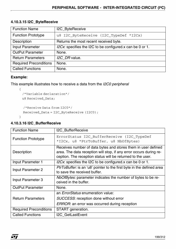
PERIPHERAL SOFTWARE - INTER-INTEGRATED CIRCUIT (I²C)
4.10.3.15 I2C_ByteReceive
Example:
This example illustrates how to receive a data from the I2C0 peripheral {
/*Variable declaration*/
u8 Received_Data;
/*Receive Data from I2C0*/
Received_Data = I2C_ByteReceive (I2C0);
}
4.10.3.16 I2C_BufferReceive
Function Name I2C_ByteReceive
Function Prototype u8 I2C_ByteReceive (I2C_TypeDef *I2Cx)
Description Returns the most recent received byte.
Input Parameter I2Cx: specifies the I2C to be configured.x can be 0 or 1.
OutPut Parameter None.
Return Parameters I2C_DR value.Required Preconditions None.
Called Functions None.
Function Name I2C_BufferReceive
Function PrototypeErrorStatus I2C_BufferReceive (I2C_TypeDef *I2Cx, u8 *PtrToBuffer, u8 NbOfBytes)
DescriptionReceives number of data bytes and stores them in user defined area. The data reception will stop, if any error occurs during re-ception. The reception status will be returned to the user.
Input Parameter 1 I2Cx: specifies the I2C to be configured.x can be 0 or 1.
Input Parameter 2PtrToBuffer: is an ‘u8’ pointer to the first byte in the defined area to save the received buffer.
Input Parameter 3NbOfBytes: parameter indicates the number of bytes to be re-ceived in the buffer.
OutPut Parameter None.
Return Parameters
an ErrorStatus enumeration value:
SUCCESS: reception done without error
ERROR: an error was occurred during receptionRequired Preconditions START generation.
Called Functions I2C_GetLastEvent
199/312
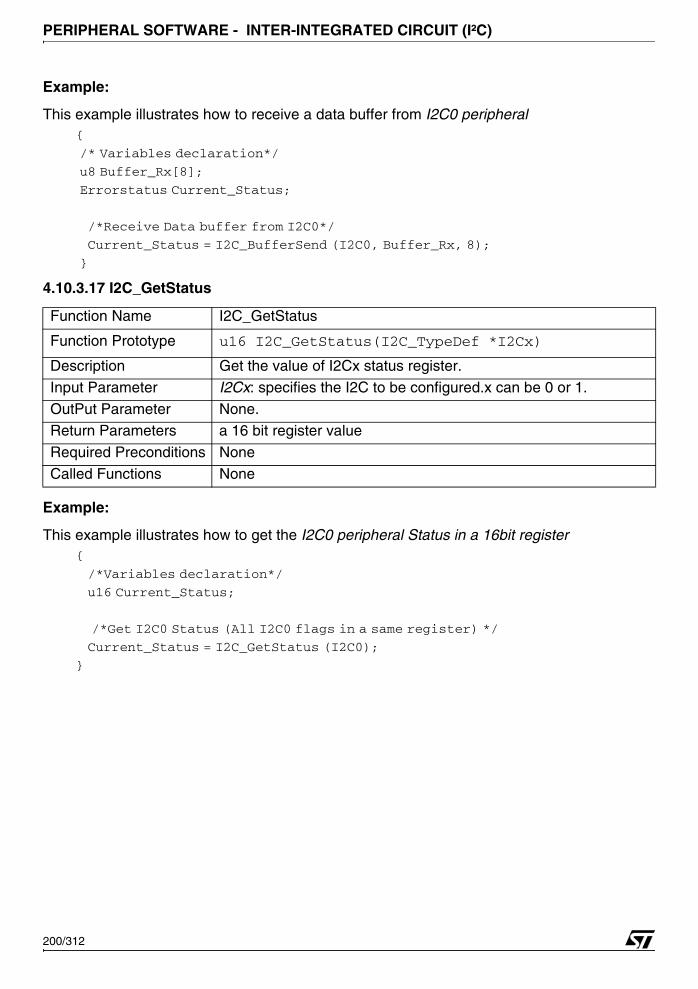
PERIPHERAL SOFTWARE - INTER-INTEGRATED CIRCUIT (I²C)
Example:
This example illustrates how to receive a data buffer from I2C0 peripheral {
/* Variables declaration*/
u8 Buffer_Rx[8];
Errorstatus Current_Status;
/*Receive Data buffer from I2C0*/
Current_Status = I2C_BufferSend (I2C0, Buffer_Rx, 8);
}
4.10.3.17 I2C_GetStatus
Example:
This example illustrates how to get the I2C0 peripheral Status in a 16bit register {
/*Variables declaration*/
u16 Current_Status;
/*Get I2C0 Status (All I2C0 flags in a same register) */
Current_Status = I2C_GetStatus (I2C0);
}
Function Name I2C_GetStatus
Function Prototype u16 I2C_GetStatus(I2C_TypeDef *I2Cx)
Description Get the value of I2Cx status register.
Input Parameter I2Cx: specifies the I2C to be configured.x can be 0 or 1.
OutPut Parameter None.Return Parameters a 16 bit register value
Required Preconditions None
Called Functions None
200/312
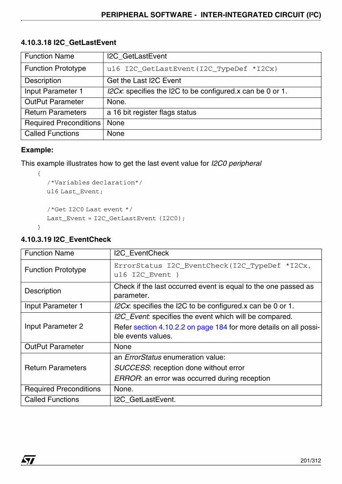
PERIPHERAL SOFTWARE - INTER-INTEGRATED CIRCUIT (I²C)
4.10.3.18 I2C_GetLastEvent
Example:
This example illustrates how to get the last event value for I2C0 peripheral {
/*Variables declaration*/
u16 Last_Event;
/*Get I2C0 Last event */
Last_Event = I2C_GetLastEvent (I2C0);
}
4.10.3.19 I2C_EventCheck
Function Name I2C_GetLastEvent
Function Prototype u16 I2C_GetLastEvent(I2C_TypeDef *I2Cx)
Description Get the Last I2C Event
Input Parameter 1 I2Cx: specifies the I2C to be configured.x can be 0 or 1.
OutPut Parameter None.
Return Parameters a 16 bit register flags statusRequired Preconditions None
Called Functions None
Function Name I2C_EventCheck
Function PrototypeErrorStatus I2C_EventCheck(I2C_TypeDef *I2Cx, u16 I2C_Event )
DescriptionCheck if the last occurred event is equal to the one passed as parameter.
Input Parameter 1 I2Cx: specifies the I2C to be configured.x can be 0 or 1.
Input Parameter 2I2C_Event: specifies the event which will be compared.
Refer section 4.10.2.2 on page 184 for more details on all possi-ble events values.
OutPut Parameter None
Return Parametersan ErrorStatus enumeration value:SUCCESS: reception done without error
ERROR: an error was occurred during reception
Required Preconditions None.
Called Functions I2C_GetLastEvent.
201/312
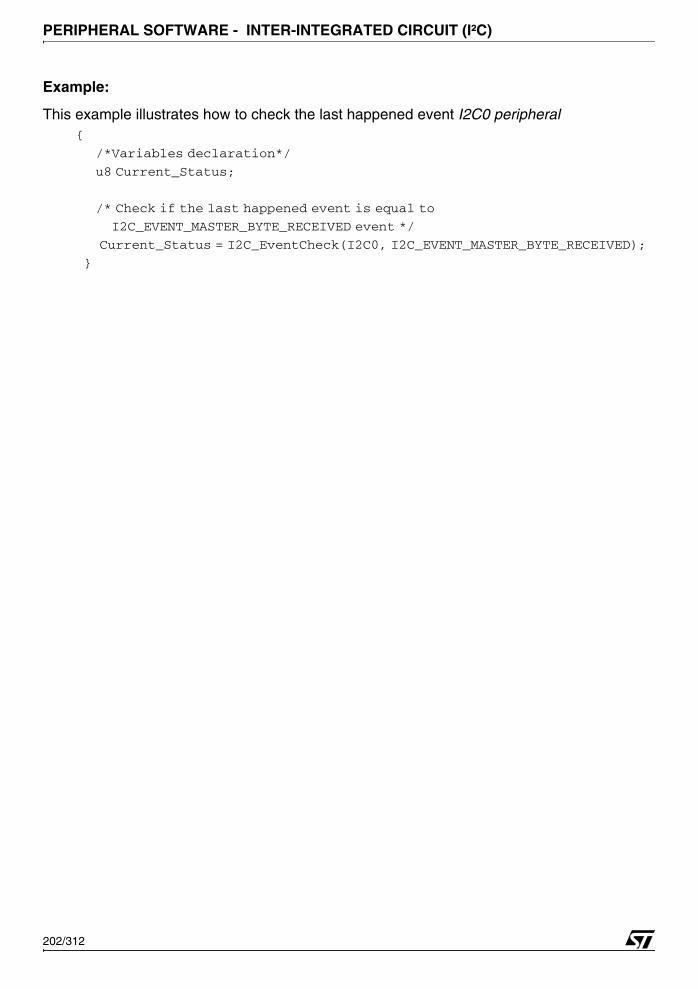
PERIPHERAL SOFTWARE - INTER-INTEGRATED CIRCUIT (I²C)
Example:
This example illustrates how to check the last happened event I2C0 peripheral {
/*Variables declaration*/
u8 Current_Status;
/* Check if the last happened event is equal to
I2C_EVENT_MASTER_BYTE_RECEIVED event */
Current_Status = I2C_EventCheck(I2C0, I2C_EVENT_MASTER_BYTE_RECEIVED);
}
202/312

PERIPHERAL SOFTWARE - POWER RESET CLOCK CONTROL UNIT (PRCCU)
4.11 POWER RESET CLOCK CONTROL UNIT (PRCCU)
The PRCCU driver may be used for a variety of purposes, including power management con-figuration, low power mode selection and clock configuration.
The first section describes the data structures used in the PRCCU software library. Thesecond section presents the PRCCU software library functions.
4.11.1 Data Structures
4.11.1.1 PRCCU Registers Structure
The PRCCU registers’ structure PRCCU_TypeDef is defined in the 73x_map.h file as follows:typedef struct
{
vu32 CCR;
vu32 VRCTR;
vu32 CFR;
u32 EMPTY1[3];
vu32 PLLCR;
u32 EMPTY2;
vu32 SMR;
u32 EMPTY3;
vu32 RTCPR;
} PRCCU_TypeDef;
The following table describes the PRCCU structure fields.:
The PRCCU peripheral is declared in the same file:...
#define PRCCU_BASE 0x60000000
...
#ifdef DEBUG
...
EXT PRCCU_TypeDef *PRCCU;
...
#else
...
#define PRCCU ((PRCCU_TypeDef *)PRCCU_BASE)
Register DescriptionCCR Clock Control Register
VRCTR Voltage Regulator Control Register
CFR Clock Flag RegisterPLLCR PLL Configuration Register
SMR System Mode Register
RTCPR Real Time Clock Programming Register
203/312
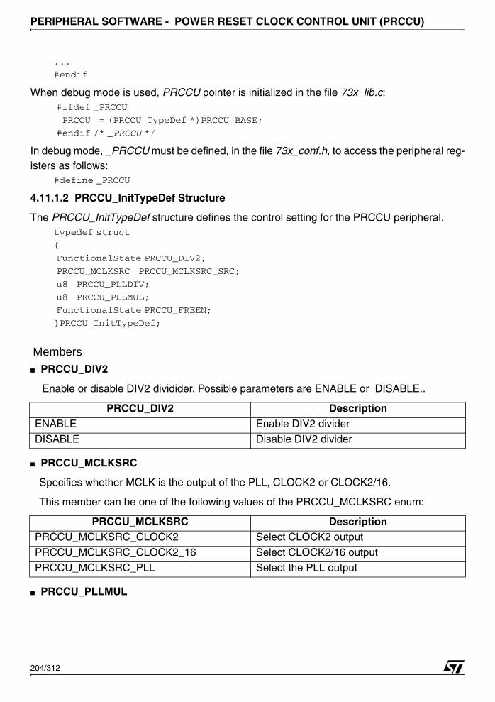
PERIPHERAL SOFTWARE - POWER RESET CLOCK CONTROL UNIT (PRCCU)
...
#endif
When debug mode is used, PRCCU pointer is initialized in the file 73x_lib.c: #ifdef _PRCCU
PRCCU = (PRCCU_TypeDef *)PRCCU_BASE;
#endif /* _PRCCU */
In debug mode, _PRCCU must be defined, in the file 73x_conf.h, to access the peripheral reg-isters as follows:
#define _PRCCU
4.11.1.2 PRCCU_InitTypeDef Structure
The PRCCU_InitTypeDef structure defines the control setting for the PRCCU peripheral.typedef struct
{
FunctionalState PRCCU_DIV2;
PRCCU_MCLKSRC PRCCU_MCLKSRC_SRC;
u8 PRCCU_PLLDIV;
u8 PRCCU_PLLMUL;
FunctionalState PRCCU_FREEN;
}PRCCU_InitTypeDef;
Members■ PRCCU_DIV2
Enable or disable DIV2 dividider. Possible parameters are ENABLE or DISABLE..
■ PRCCU_MCLKSRC
Specifies whether MCLK is the output of the PLL, CLOCK2 or CLOCK2/16.
This member can be one of the following values of the PRCCU_MCLKSRC enum:
■ PRCCU_PLLMUL
PRCCU_DIV2 DescriptionENABLE Enable DIV2 divider
DISABLE Disable DIV2 divider
PRCCU_MCLKSRC DescriptionPRCCU_MCLKSRC_CLOCK2 Select CLOCK2 output
PRCCU_MCLKSRC_CLOCK2_16 Select CLOCK2/16 output
PRCCU_MCLKSRC_PLL Select the PLL output
204/312

PERIPHERAL SOFTWARE - POWER RESET CLOCK CONTROL UNIT (PRCCU)
Specifies the Multiplication factors of the PLL.
■ PRCCU_PLLDIV
Specifies the Divider factors of the PLL
■ PRCCU_FREEN
Enable or disable the Free Running Mode for the PLL
4.11.1.3 PRCCU_OUTPUT
The following table describes the different PRCCU module outputs
PRCCU_PLLMUL DescriptionPRCCU_PLLMUL_28 CLOCK2 * 28
PRCCU_PLLMUL_20 CLOCK2 * 20
PRCCU_PLLMUL_16 CLOCK2 * 16PRCCU_PLLMUL_12 CLOCK2 * 12
PRCCU_PLLDIV DescriptionPRCCU_PLLDIV_1 PLL CLOCK /1
PRCCU_PLLDIV_2 PLL CLOCK /2
PRCCU_PLLDIV_3 PLL CLOCK /3PRCCU_PLLDIV_4 PLL CLOCK /4
PRCCU_PLLDIV_5 PLL CLOCK /5
PRCCU_PLLDIV_6 PLL CLOCK /6
PRCCU_PLLDIV_7 PLL CLOCK /7
PRCCU_FREEN DescriptionENABLE Enable free running mode
DISABLE Disable free running mode
PRCCU_OUTPUT DescriptionPRCCU_CLOCK_EXT EXT frequency to TIM, RTC, WDG and Timers TB
PRCCU_CLOCK_MCLK MCLK frequency to CPU and peripherals
205/312

PERIPHERAL SOFTWARE - POWER RESET CLOCK CONTROL UNIT (PRCCU)
4.11.1.4 PRCCU Voltage Regulators
The following table describes the PRCCU voltage regulators
4.11.1.5 PRCCU Low Power Modes
The following table describes the different Low Power Modes:
4.11.1.6 PRCCU Flags
The PRCCU Flags defined in 73x_prccu.h, are listed below:
4.11.1.7 PRCCU Interrupt
The PRCCU interrupts defined in 73x_prccu.h, are listed below:
Voltage Regulators DescriptionPRCCU_VR_LPWFI Main Voltage Regulator in LPWFI Mode
PRCCU_VR_Run Main Voltage Regulator in Run Mode
Low Power Modes DescriptionPRCCU_LPM_HALT HALT Low power mode
PRCCU_LPM_WFI WFI Low power mode
PRCCU_LPM_LPWFI LPWFI Low power mode
PRCCU Flags DescriptionPRCCU_FLAG_STOP_I STOP Interrupt pending bit
PRCCU_FLAG_CK2_16_I CK2_16 switching Interrupt pending bitPRCCU_FLAG_LOCK_I LOCK Interrupt pending bit
PRCCU_FLAG_LVD_INT Internal LVD reset flag
PRCCU_FLAG_WDGRES Watchdog reset flag.
PRCCU_FLAG_SOFTRES Software Reset Flag
PRCCU_FLAG_LOCK PLL locked-in
PRCCU_FLAG_VROK Voltage Regulator OK
PRCCU Interrupts DescriptionPRCCU_IT_CK2_16 CLK2/16 divider interrupt mask.PRCCU_IT_Lock PLL Lock interrupt mask.
PRCCU_IT_Stop Stop interrupt mask.
206/312
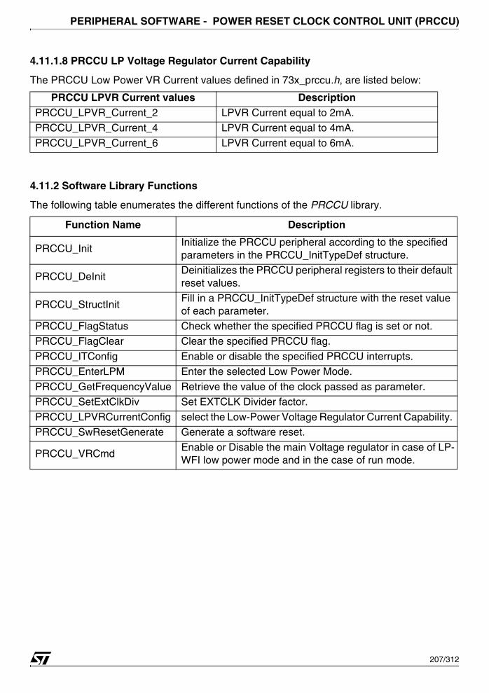
PERIPHERAL SOFTWARE - POWER RESET CLOCK CONTROL UNIT (PRCCU)
4.11.1.8 PRCCU LP Voltage Regulator Current Capability
The PRCCU Low Power VR Current values defined in 73x_prccu.h, are listed below:
4.11.2 Software Library Functions
The following table enumerates the different functions of the PRCCU library.
PRCCU LPVR Current values DescriptionPRCCU_LPVR_Current_2 LPVR Current equal to 2mA.
PRCCU_LPVR_Current_4 LPVR Current equal to 4mA.
PRCCU_LPVR_Current_6 LPVR Current equal to 6mA.
Function Name Description
PRCCU_InitInitialize the PRCCU peripheral according to the specified parameters in the PRCCU_InitTypeDef structure.
PRCCU_DeInitDeinitializes the PRCCU peripheral registers to their default reset values.
PRCCU_StructInitFill in a PRCCU_InitTypeDef structure with the reset value of each parameter.
PRCCU_FlagStatus Check whether the specified PRCCU flag is set or not.PRCCU_FlagClear Clear the specified PRCCU flag.
PRCCU_ITConfig Enable or disable the specified PRCCU interrupts.
PRCCU_EnterLPM Enter the selected Low Power Mode.
PRCCU_GetFrequencyValue Retrieve the value of the clock passed as parameter.
PRCCU_SetExtClkDiv Set EXTCLK Divider factor.
PRCCU_LPVRCurrentConfig select the Low-Power Voltage Regulator Current Capability.
PRCCU_SwResetGenerate Generate a software reset.
PRCCU_VRCmdEnable or Disable the main Voltage regulator in case of LP-WFI low power mode and in the case of run mode.
207/312
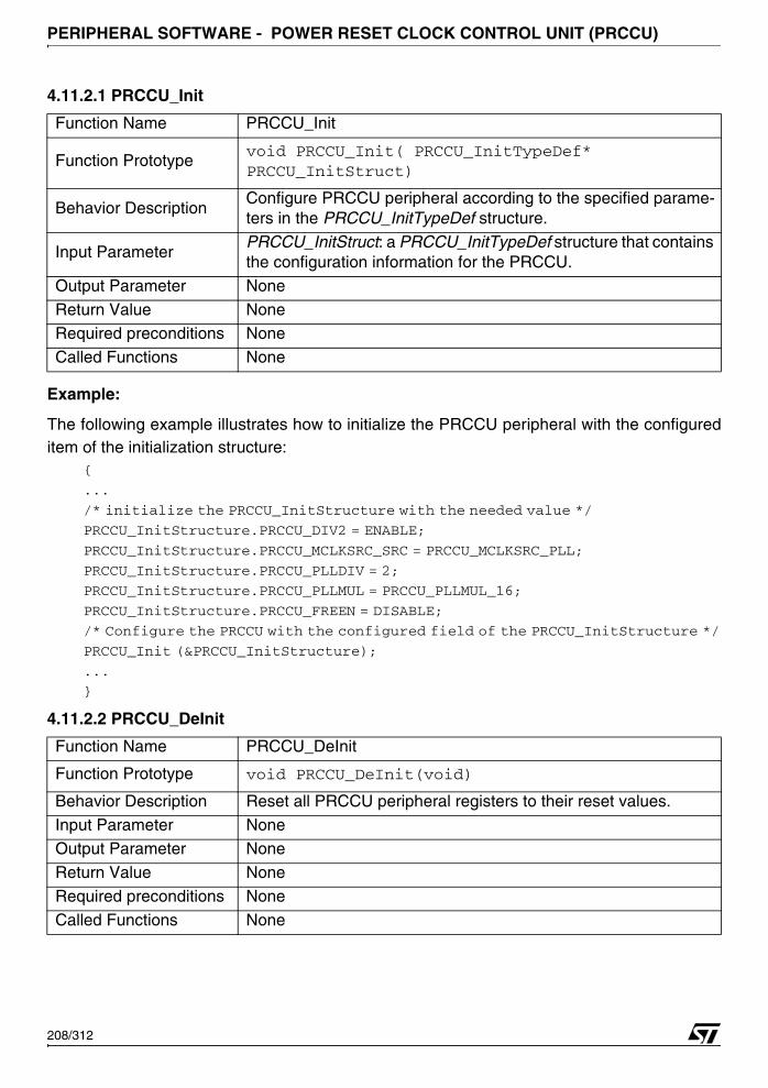
PERIPHERAL SOFTWARE - POWER RESET CLOCK CONTROL UNIT (PRCCU)
4.11.2.1 PRCCU_Init
Example:
The following example illustrates how to initialize the PRCCU peripheral with the configureditem of the initialization structure:
{
...
/* initialize the PRCCU_InitStructure with the needed value */
PRCCU_InitStructure.PRCCU_DIV2 = ENABLE;
PRCCU_InitStructure.PRCCU_MCLKSRC_SRC = PRCCU_MCLKSRC_PLL;
PRCCU_InitStructure.PRCCU_PLLDIV = 2;
PRCCU_InitStructure.PRCCU_PLLMUL = PRCCU_PLLMUL_16;
PRCCU_InitStructure.PRCCU_FREEN = DISABLE;
/* Configure the PRCCU with the configured field of the PRCCU_InitStructure */
PRCCU_Init (&PRCCU_InitStructure);
...
}
4.11.2.2 PRCCU_DeInit
Function Name PRCCU_Init
Function Prototypevoid PRCCU_Init( PRCCU_InitTypeDef* PRCCU_InitStruct)
Behavior DescriptionConfigure PRCCU peripheral according to the specified parame-ters in the PRCCU_InitTypeDef structure.
Input ParameterPRCCU_InitStruct: a PRCCU_InitTypeDef structure that contains the configuration information for the PRCCU.
Output Parameter None
Return Value NoneRequired preconditions None
Called Functions None
Function Name PRCCU_DeInit
Function Prototype void PRCCU_DeInit(void)
Behavior Description Reset all PRCCU peripheral registers to their reset values.
Input Parameter NoneOutput Parameter None
Return Value None
Required preconditions None
Called Functions None
208/312
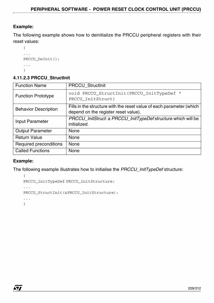
PERIPHERAL SOFTWARE - POWER RESET CLOCK CONTROL UNIT (PRCCU)
Example:
The following example shows how to deinitialize the PRCCU peripheral registers with theirreset values:
{
...
PRCCU_DeInit();
...
}
4.11.2.3 PRCCU_StructInit
Example:
The following example illustrates how to initialise the PRCCU_InitTypeDef structure:{
PRCCU_InitTypeDef PRCCU_InitStructure;
...
PRCCU_StructInit(&PRCCU_InitStructure);
...
}
Function Name PRCCU_StructInit
Function Prototypevoid PRCCU_StructInit(PRCCU_InitTypeDef * PRCCU_InitStruct)
Behavior DescriptionFills in the structure with the reset value of each parameter (which depend on the register reset value).
Input ParameterPRCCU_InitStruct: a PRCCU_InitTypeDef structure which will be initialized.
Output Parameter NoneReturn Value None
Required preconditions None
Called Functions None
209/312

PERIPHERAL SOFTWARE - POWER RESET CLOCK CONTROL UNIT (PRCCU)
4.11.2.4 PRCCU_FlagStatus
Example:
The following example illustrates how to check if the last reset was done by the watchdog:{
...
if (PRCCU_FlagStatus(PRCCU_FLAG_WDGRES))
{
...
}
...
}
4.11.2.5 PRCCU_FlagClear
Function Name PRCCU_FlagStatus
Function Prototype FlagStatus PRCCU_FlagStatus (u16 PRCCU_Flag)
Behavior Description Check whether the specified PRCCU flag is set or not.
Input ParameterPRCCU_Flag: flag to check.
Refer to section 4.11.1.6 on page 206 for more details on the al-lowed values of this parameter.
Output Parameter None
Return ValueThe status of the specified flag.
It can be either SET or RESET:
Required preconditions None
Called Functions None
Function Name PRCCU_FlagClear
Function Prototype Clear the specified PRCCU flag
Behavior Description void PRCCU_FlagClear (u16 PRCCU_Flag);
Input ParameterPRCCU_Flag: flag to clear. For more details on the allowed val-ues, refer to section 4.11.1.6 on page 206
Output Parameter NoneReturn Value None
Required preconditions None
Called Functions None
210/312
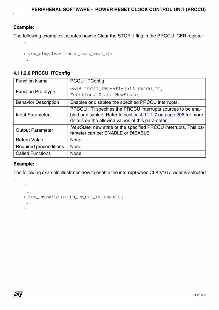
PERIPHERAL SOFTWARE - POWER RESET CLOCK CONTROL UNIT (PRCCU)
Example:
The following example illustrates how to Clear the STOP_I flag in the PRCCU_CFR register :{
...
PRCCU_FlagClear (PRCCU_FLAG_STOP_I);
...
}
4.11.2.6 PRCCU_ITConfig
Example:
The following example illustrates how to enable the interrupt when CLK2/16 divider is selected:
{
...
PRCCU_ITConfig (PRCCU_IT_CK2_16, ENABLE);
...
}
Function Name RCCU_ITConfig
Function Prototypevoid PRCCU_ITConfig(u16 PRCCU_IT, FunctionalState NewState)
Behavior Description Enables or disables the specified PRCCU interrupts.
Input ParameterPRCCU_IT: specifies the PRCCU interrupts sources to be ena-bled or disabled. Refer to section 4.11.1.7 on page 206 for more details on the allowed values of this parameter.
Output ParameterNewState: new state of the specified PRCCU interrupts. This pa-rameter can be: ENABLE or DISABLE.
Return Value None
Required preconditions None
Called Functions None
211/312
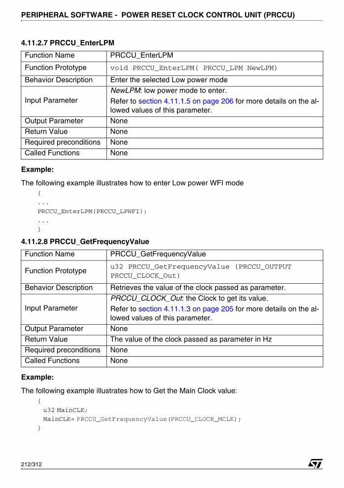
PERIPHERAL SOFTWARE - POWER RESET CLOCK CONTROL UNIT (PRCCU)
4.11.2.7 PRCCU_EnterLPM
Example:
The following example illustrates how to enter Low power WFI mode {
...
PRCCU_EnterLPM(PRCCU_LPWFI);
...
}
4.11.2.8 PRCCU_GetFrequencyValue
Example:
The following example illustrates how to Get the Main Clock value: {
u32 MainCLK;
MainCLK= PRCCU_GetFrequencyValue(PRCCU_CLOCK_MCLK);}
Function Name PRCCU_EnterLPM
Function Prototype void PRCCU_EnterLPM( PRCCU_LPM NewLPM)
Behavior Description Enter the selected Low power mode
Input ParameterNewLPM: low power mode to enter.
Refer to section 4.11.1.5 on page 206 for more details on the al-lowed values of this parameter.
Output Parameter None
Return Value None
Required preconditions None
Called Functions None
Function Name PRCCU_GetFrequencyValue
Function Prototypeu32 PRCCU_GetFrequencyValue (PRCCU_OUTPUT PRCCU_CLOCK_Out)
Behavior Description Retrieves the value of the clock passed as parameter.
Input ParameterPRCCU_CLOCK_Out: the Clock to get its value.Refer to section 4.11.1.3 on page 205 for more details on the al-lowed values of this parameter.
Output Parameter NoneReturn Value The value of the clock passed as parameter in Hz
Required preconditions None
Called Functions None
212/312
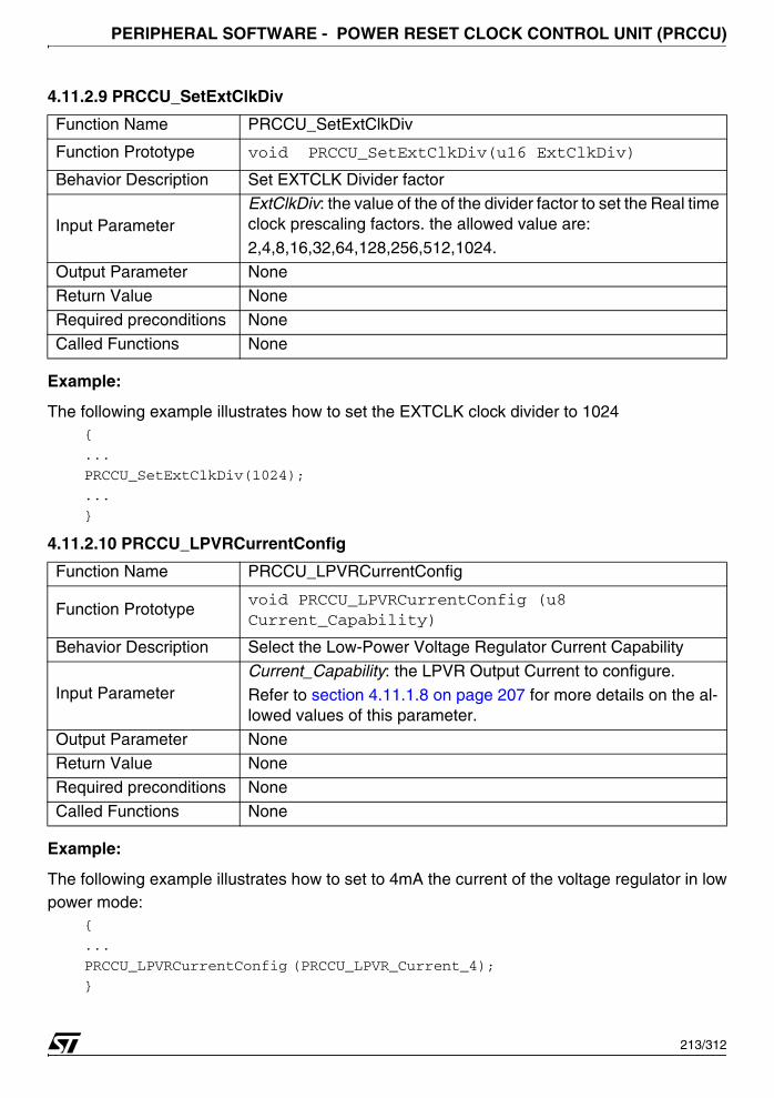
PERIPHERAL SOFTWARE - POWER RESET CLOCK CONTROL UNIT (PRCCU)
4.11.2.9 PRCCU_SetExtClkDiv
Example:
The following example illustrates how to set the EXTCLK clock divider to 1024{
...
PRCCU_SetExtClkDiv(1024);
...
}
4.11.2.10 PRCCU_LPVRCurrentConfig
Example:
The following example illustrates how to set to 4mA the current of the voltage regulator in lowpower mode:
{
...
PRCCU_LPVRCurrentConfig (PRCCU_LPVR_Current_4);
}
Function Name PRCCU_SetExtClkDiv
Function Prototype void PRCCU_SetExtClkDiv(u16 ExtClkDiv)
Behavior Description Set EXTCLK Divider factor
Input ParameterExtClkDiv: the value of the of the divider factor to set the Real time clock prescaling factors. the allowed value are:2,4,8,16,32,64,128,256,512,1024.
Output Parameter None
Return Value None
Required preconditions None
Called Functions None
Function Name PRCCU_LPVRCurrentConfig
Function Prototypevoid PRCCU_LPVRCurrentConfig (u8 Current_Capability)
Behavior Description Select the Low-Power Voltage Regulator Current Capability
Input ParameterCurrent_Capability: the LPVR Output Current to configure.Refer to section 4.11.1.8 on page 207 for more details on the al-lowed values of this parameter.
Output Parameter NoneReturn Value None
Required preconditions None
Called Functions None
213/312
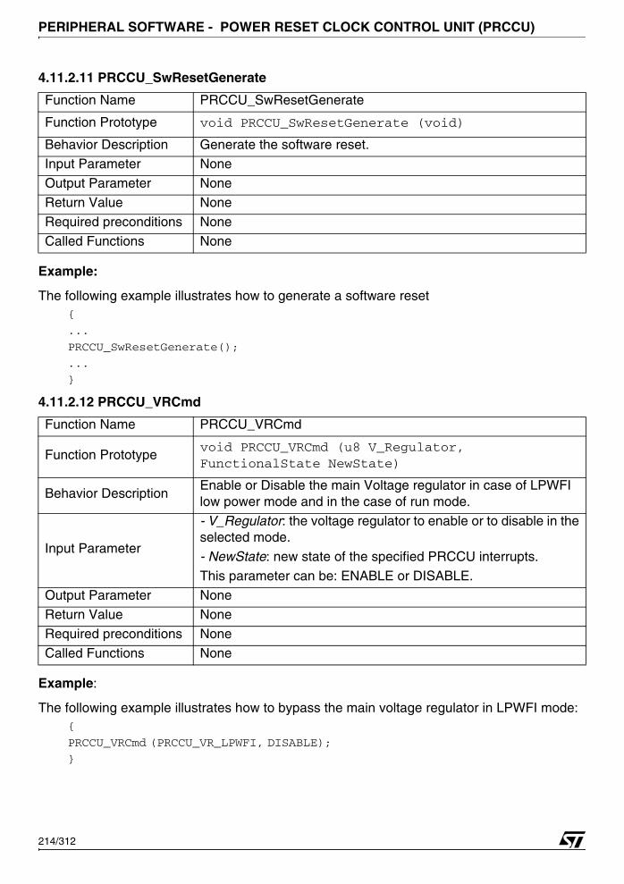
PERIPHERAL SOFTWARE - POWER RESET CLOCK CONTROL UNIT (PRCCU)
4.11.2.11 PRCCU_SwResetGenerate
Example:
The following example illustrates how to generate a software reset {
...
PRCCU_SwResetGenerate();
...
}
4.11.2.12 PRCCU_VRCmd
Example:
The following example illustrates how to bypass the main voltage regulator in LPWFI mode:{
PRCCU_VRCmd (PRCCU_VR_LPWFI, DISABLE);
}
Function Name PRCCU_SwResetGenerate
Function Prototype void PRCCU_SwResetGenerate (void)
Behavior Description Generate the software reset.Input Parameter None
Output Parameter None
Return Value None
Required preconditions None
Called Functions None
Function Name PRCCU_VRCmd
Function Prototypevoid PRCCU_VRCmd (u8 V_Regulator, FunctionalState NewState)
Behavior DescriptionEnable or Disable the main Voltage regulator in case of LPWFI low power mode and in the case of run mode.
Input Parameter
- V_Regulator: the voltage regulator to enable or to disable in the selected mode.
- NewState: new state of the specified PRCCU interrupts.
This parameter can be: ENABLE or DISABLE.
Output Parameter NoneReturn Value None
Required preconditions None
Called Functions None
214/312
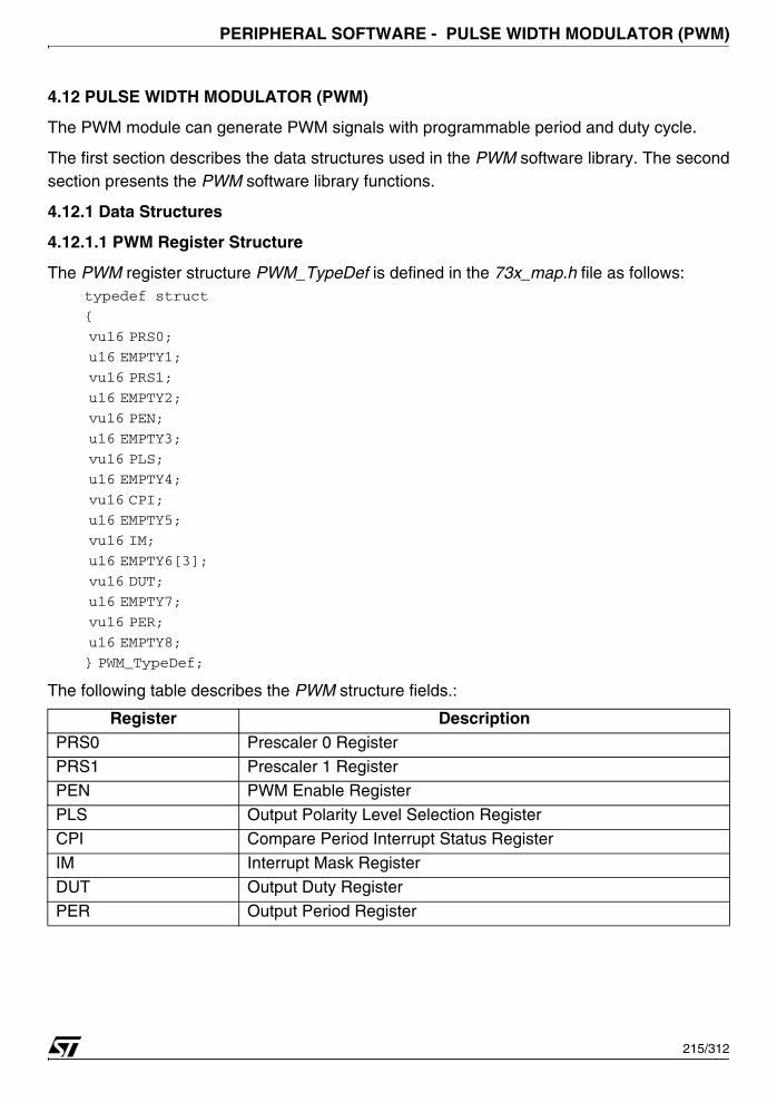
PERIPHERAL SOFTWARE - PULSE WIDTH MODULATOR (PWM)
4.12 PULSE WIDTH MODULATOR (PWM)
The PWM module can generate PWM signals with programmable period and duty cycle.
The first section describes the data structures used in the PWM software library. The secondsection presents the PWM software library functions.
4.12.1 Data Structures
4.12.1.1 PWM Register Structure
The PWM register structure PWM_TypeDef is defined in the 73x_map.h file as follows:typedef struct
{
vu16 PRS0;
u16 EMPTY1;
vu16 PRS1;
u16 EMPTY2;
vu16 PEN;
u16 EMPTY3;
vu16 PLS;
u16 EMPTY4;
vu16 CPI;
u16 EMPTY5;
vu16 IM;
u16 EMPTY6[3];
vu16 DUT;
u16 EMPTY7;
vu16 PER;
u16 EMPTY8;
} PWM_TypeDef;
The following table describes the PWM structure fields.:
Register DescriptionPRS0 Prescaler 0 Register
PRS1 Prescaler 1 RegisterPEN PWM Enable Register
PLS Output Polarity Level Selection Register
CPI Compare Period Interrupt Status Register
IM Interrupt Mask Register
DUT Output Duty Register
PER Output Period Register
215/312
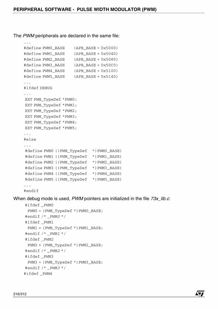
PERIPHERAL SOFTWARE - PULSE WIDTH MODULATOR (PWM)
The PWM peripherals are declared in the same file:...
#define PWM0_BASE (APB_BASE + 0x5000)
#define PWM1_BASE (APB_BASE + 0x5040)
#define PWM2_BASE (APB_BASE + 0x5080)
#define PWM3_BASE (APB_BASE + 0x50C0)
#define PWM4_BASE (APB_BASE + 0x5100)
#define PWM5_BASE (APB_BASE + 0x5140)
...
#ifdef DEBUG
...
EXT PWM_TypeDef *PWM0;
EXT PWM_TypeDef *PWM1;
EXT PWM_TypeDef *PWM2;
EXT PWM_TypeDef *PWM3;
EXT PWM_TypeDef *PWM4;
EXT PWM_TypeDef *PWM5;
...
#else
...
#define PWM0 ((PWM_TypeDef *)PWM0_BASE)
#define PWM1 ((PWM_TypeDef *)PWM1_BASE)
#define PWM2 ((PWM_TypeDef *)PWM2_BASE)
#define PWM3 ((PWM_TypeDef *)PWM3_BASE)
#define PWM4 ((PWM_TypeDef *)PWM4_BASE)
#define PWM5 ((PWM_TypeDef *)PWM5_BASE)
...
#endif
When debug mode is used, PWM pointers are initialized in the file 73x_lib.c: #ifdef _PWM0
PWM0 = (PWM_TypeDef *)PWM0_BASE;
#endif /* _PWM0 */
#ifdef _PWM1
PWM1 = (PWM_TypeDef *)PWM1_BASE;
#endif /* _PWM1 */
#ifdef _PWM2
PWM2 = (PWM_TypeDef *)PWM2_BASE;
#endif /* _PWM2 */
#ifdef _PWM3
PWM3 = (PWM_TypeDef *)PWM3_BASE;
#endif /* _PWM3 */
#ifdef _PWM4
216/312

PERIPHERAL SOFTWARE - PULSE WIDTH MODULATOR (PWM)
PWM4 = (PWM_TypeDef *)PWM4_BASE;
#endif /* _PWM4 */
#ifdef _PWM5
PWM5 = (PWM_TypeDef *)PWM5_BASE;
#endif /* _PWM5 */
In debug mode, _PWMx must be defined, in the file 73x_conf.h, to access the peripheral reg-isters as follows:
#define _PWMx (x=0..5)
4.12.1.2 PWM Values
The following table enumerates the different values of the PWMx:
4.12.1.3 PWM_InitTypeDef Structure
The PWM_InitTypeDef structure defines the control setting for the Pulse Width Modulation pe-ripheral.
typedef struct
{ u8 PWM_Prescaler0;
u8 PWM_Prescaler1;
u16 PWM_DutyCycle;
u16 PWM_Period;
u8 PWM_Polarity_Level;
} PWM_InitTypeDef;
Members■ PWM_Prescaler0
Specifies the value of the Prescaler 0. The clock CK is divided by
The PWM_Prescale0 value must be between 0 and 7.
■ PWM_Prescaler
Specifies the value of the Prescaler1. The clock CK is divided byPR1[4:0]+1.
The PWM_Prescale1 value must be between 0 and 31.
■ PWM_DutyCycle
PWM Value DescriptionPWM0 Pulse Width Modulation 0
PWM1 Pulse Width Modulation 1
PWM2 Pulse Width Modulation 2PWM3 Pulse Width Modulation 3
PWM4 Pulse Width Modulation 4
PWM5 Pulse Width Modulation 5
2PR0(2:0]
217/312
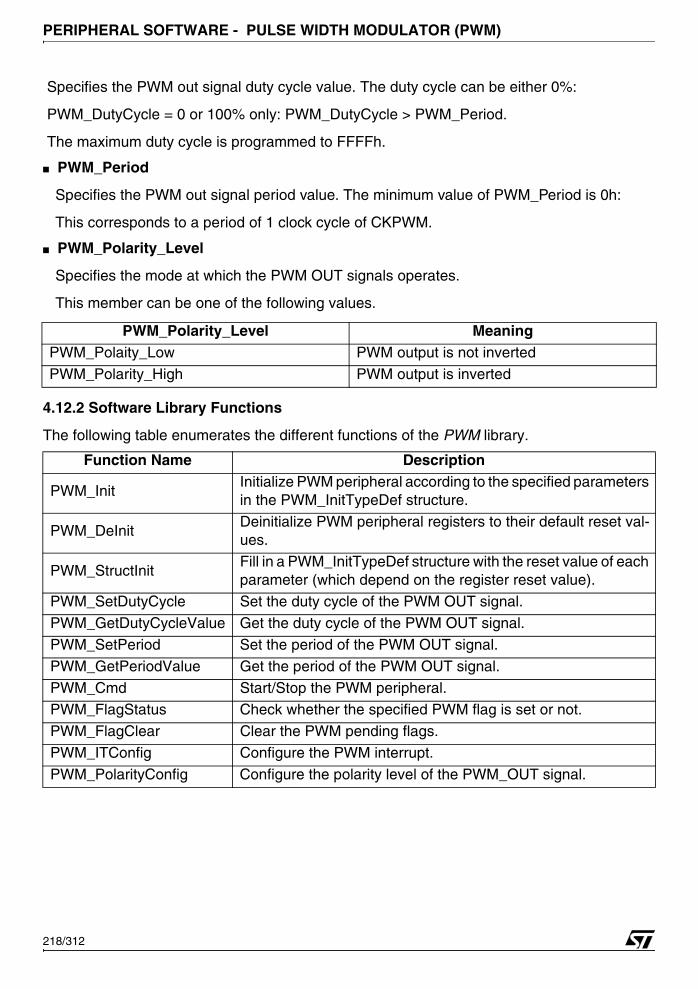
PERIPHERAL SOFTWARE - PULSE WIDTH MODULATOR (PWM)
Specifies the PWM out signal duty cycle value. The duty cycle can be either 0%:
PWM_DutyCycle = 0 or 100% only: PWM_DutyCycle > PWM_Period.
The maximum duty cycle is programmed to FFFFh.
■ PWM_Period
Specifies the PWM out signal period value. The minimum value of PWM_Period is 0h:
This corresponds to a period of 1 clock cycle of CKPWM.
■ PWM_Polarity_Level
Specifies the mode at which the PWM OUT signals operates.
This member can be one of the following values.
4.12.2 Software Library Functions
The following table enumerates the different functions of the PWM library.
PWM_Polarity_Level MeaningPWM_Polaity_Low PWM output is not inverted
PWM_Polarity_High PWM output is inverted
Function Name Description
PWM_InitInitialize PWM peripheral according to the specified parameters in the PWM_InitTypeDef structure.
PWM_DeInitDeinitialize PWM peripheral registers to their default reset val-ues.
PWM_StructInitFill in a PWM_InitTypeDef structure with the reset value of each parameter (which depend on the register reset value).
PWM_SetDutyCycle Set the duty cycle of the PWM OUT signal.
PWM_GetDutyCycleValue Get the duty cycle of the PWM OUT signal.
PWM_SetPeriod Set the period of the PWM OUT signal.
PWM_GetPeriodValue Get the period of the PWM OUT signal.
PWM_Cmd Start/Stop the PWM peripheral.PWM_FlagStatus Check whether the specified PWM flag is set or not.
PWM_FlagClear Clear the PWM pending flags.
PWM_ITConfig Configure the PWM interrupt.
PWM_PolarityConfig Configure the polarity level of the PWM_OUT signal.
218/312
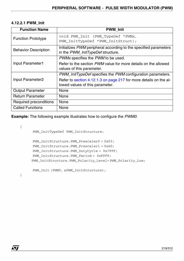
PERIPHERAL SOFTWARE - PULSE WIDTH MODULATOR (PWM)
4.12.2.1 PWM_Init
Example: The following example illustrates how to configure the PWM0:
{
PWM_InitTypeDef PWM_InitStructure;
PWM_InitStructure.PWM_Prescaler0 = 0x03;
PWM_InitStructure.PWM_Prescaler1 = 0xA0;
PWM_InitStructure.PWM_DutyCycle = 0x7FFF;
PWM_InitStructure.PWM_Period = 0xFFFF;
PWM_InitStructure.PWM_Polarity_Level= PWM_Polarity_Low;
PWM_Init (PWM0, &PWM_InitStructure);
}
Function Name PWM_Init
Function Prototypevoid PWM_Init (PWM_TypeDef *PWMx, PWM_InitTypeDef *PWM_InitStruct);
Behavior DescriptionInitializes PWM peripheral according to the specified parameters in the PWM_InitTypeDef structure.
Input Parameter1PWMx specifies the PWM to be used.
Refer to the section PWM value for more details on the allowed values of this parameter.
Input Parameter2PWM_InitTypeDef specifies the PWM configuration parameters.Refer to section 4.12.1.3 on page 217 for more details on the al-lowed values of this parameter.
Output Parameter None
Return Parameter None
Required preconditions None
Called Functions None
219/312
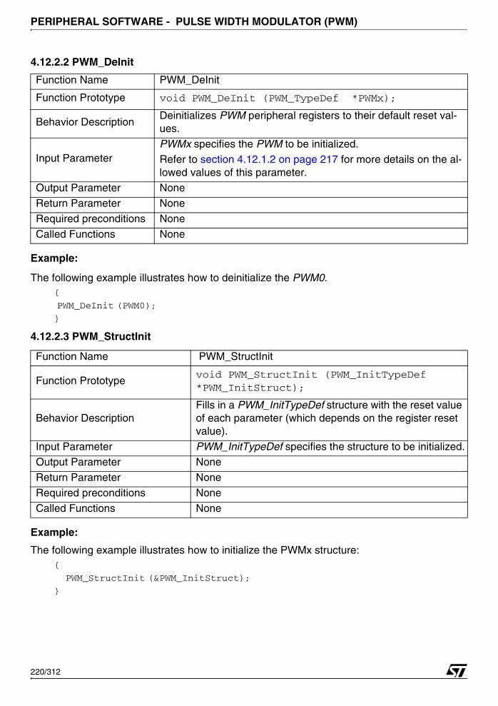
PERIPHERAL SOFTWARE - PULSE WIDTH MODULATOR (PWM)
4.12.2.2 PWM_DeInit
Example:
The following example illustrates how to deinitialize the PWM0.{
PWM_DeInit (PWM0);
}
4.12.2.3 PWM_StructInit
Example:
The following example illustrates how to initialize the PWMx structure:{
PWM_StructInit (&PWM_InitStruct);
}
Function Name PWM_DeInit
Function Prototype void PWM_DeInit (PWM_TypeDef *PWMx);
Behavior DescriptionDeinitializes PWM peripheral registers to their default reset val-ues.
Input ParameterPWMx specifies the PWM to be initialized.Refer to section 4.12.1.2 on page 217 for more details on the al-lowed values of this parameter.
Output Parameter None
Return Parameter None
Required preconditions None
Called Functions None
Function Name PWM_StructInit
Function Prototypevoid PWM_StructInit (PWM_InitTypeDef *PWM_InitStruct);
Behavior DescriptionFills in a PWM_InitTypeDef structure with the reset value of each parameter (which depends on the register reset value).
Input Parameter PWM_InitTypeDef specifies the structure to be initialized.
Output Parameter None
Return Parameter None
Required preconditions None
Called Functions None
220/312

PERIPHERAL SOFTWARE - PULSE WIDTH MODULATOR (PWM)
4.12.2.4 PWM_SetDutyCycle
Example:
The following example illustrates how to set the duty cycle of the PWM3.{
PWM_SetDutyCycle(PWM3, 0xFF05);
}
4.12.2.5 PWM_GetDutyCycleValue
Example:
The following example illustrates how to get the duty cycle value of PWM3:{
u16 MyPWMDuty;
MyPWMDuty = PWM_GetDutyCycleValue(PWM3);
}
Function Name PWM_SetDutyCycle
Function Prototypevoid PWM_SetDutyCycle ( PWM_TypeDef *PWMx, u16 PWM_Duty);
Behavior Description This routine is used to set the PWM duty cycle value.
Input Parameter 1PWMx specifies the PWM to be used.
Refer to section 4.12.1.2 on page 217 for more details on the allowed values of this parameter.
Input Parameter 2 The value of duty cycle to be set.
Output Parameter None
Return Parameter NoneRequired preconditions None
Called Functions None
Function Name PWM_GetDutyCycleValue
Function Prototypeu16 PWM_GetDutyCycleValue ( PWM_TypeDef *PWMx);
Behavior Description This routine is used to get the PWM duty cycle value.
Input Parameter 1PWMx specifies the PWM to be used.
Refer to section 4.12.1.2 on page 217 for more details on the allowed values of this parameter.
Output Parameter None
Return Parameter The duty cycle of the PWM OUT signal
Required preconditions None
Called Functions None
221/312

PERIPHERAL SOFTWARE - PULSE WIDTH MODULATOR (PWM)
4.12.2.6 PWM_SetPeriod
Example:
The following example illustrates how to set the PWM3 period value.{
PWM_SetPeriod(PWM3, 0xFFF5);...
}
4.12.2.7 PWM_GetPeriodValue
Example:
The following example illustrates how to get the PWM3 period value{
u16 MyPWMPeriod;
MyPWMPeriod = PWM_GetPeriodValue(PWM3);
...
}
Function Name PWM_SetPeriod
Function Prototypevoid PWM_SetPeriod ( PWM_TypeDef *PWMx, u16 PWM_Period);
Behavior Description This routine is used to set the PWM period value.
Input Parameter 1PWMx specifies the PWM to be used.
Refer to section 4.12.1.2 on page 217 for more details on the allowed values of this parameter.
Input Parameter 2 Period specifies the PWM Period to be set.
Output Parameter None
Return Parameter NoneRequired preconditions None
Called Functions None
Function Name PWM_GetPeriodValue
Function Prototype u16 PWM_GetPeriodValue ( PWM_TypeDef *PWMx);
Behavior Description This routine is used to get the PWM period value.
Input Parameter PWMx specifies the PWM to be used.
Refer to section 4.12.1.2 on page 217 for more details on the al-lowed values of this parameter.
Output Parameter None
Return Parameter The period of the PWM OUT signal
Required preconditions NoneCalled Functions None
222/312

PERIPHERAL SOFTWARE - PULSE WIDTH MODULATOR (PWM)
4.12.2.8 PWM_Cmd
Example:
The following example illustrates how to enable the PWM2:{
PWM_Cmd ( PWM2, ENABLE );...
}
4.12.2.9 PWM_FlagStatus
Example:
The following example illustrates how to check the PWM flag{
FlagStatus PWMFlagStatus;
PWMFlagStatus = PWM_FlagStatus (PWM0);
...
}
Function Name PWM_Cmd
Function Prototypevoid PWM_Cmd (PWM_TypeDef *PWMx, FunctionalState Newstate)
Behavior Description This routine is used to control the PWM counter.
Input Parameter 1 PWMx specifies the PWM to be used.
Input Parameter 2
Newstate: specifies the operation of the counter.
ENABLE: Starts the PWM peripheral.
DISABLE: Stops PWM peripheral.Output Parameter None
Return Parameter None
Required preconditions None
Called Functions None
Function Name PWM_FlagStatus
Function Prototype FlagStatus PWM_FlagStatus (PWM_TypeDef *PWMx);
Behavior Description Check whether the specified PWM flag is set or not.
Input Parameter PWMx specifies the PWM to be used.
Output Parameter NoneReturn Parameter The flag state (SET or RESET)
Required preconditions None
Called Functions None
223/312

PERIPHERAL SOFTWARE - PULSE WIDTH MODULATOR (PWM)
4.12.2.10 PWM_FlagClear
Example:
The following example illustrates how to clear the compare period interrupt flag:{
PWM_FlagClear ( PWM0 ) ;}
4.12.2.11 PWM_ITConfig
Example:
The following example illustrates how to enable the CPI of the PWM1:{
PWM_ITConfig (PWM1, ENABLE);
}
Function Name PWM_FlagClear
Function Prototype void PWM_FlagClear (PWM_TypeDef *PWMx);
Behavior Description Clear the specified PWM flag.
Input ParameterPWMx specifies the PWM to be used.
Refer to section 4.12.1.2 on page 217 for more details on the allowed values of this parameter.
Output Parameter None
Return Parameter NoneRequired preconditions None
Called Functions None
Function Name PWM_ITConfig
Function Prototypevoid PWM_ITConfig (PWM_TypeDef *PWMx,FunctionalState Newstate)
Behavior Description This routine is used to configure the PWM interrupts.Input Parameter 1 PWMx specifies the PWM to be used.
Input Parameter 2
Newstate: specifies the PWM interrupt state whether it would be enabled or disabled.
ENABLE: the corresponding PWM interrupt will be enabled.
DISABLE: the corresponding PWM interrupt will be disabled.
Output Parameter None
Return Parameter None
Required preconditions NoneCalled Functions None
224/312
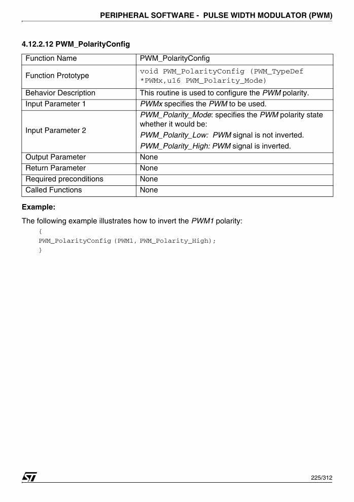
PERIPHERAL SOFTWARE - PULSE WIDTH MODULATOR (PWM)
4.12.2.12 PWM_PolarityConfig
Example:
The following example illustrates how to invert the PWM1 polarity:{
PWM_PolarityConfig (PWM1, PWM_Polarity_High);
}
Function Name PWM_PolarityConfig
Function Prototypevoid PWM_PolarityConfig (PWM_TypeDef *PWMx,u16 PWM_Polarity_Mode)
Behavior Description This routine is used to configure the PWM polarity.
Input Parameter 1 PWMx specifies the PWM to be used.
Input Parameter 2
PWM_Polarity_Mode: specifies the PWM polarity state whether it would be:
PWM_Polarity_Low: PWM signal is not inverted.
PWM_Polarity_High: PWM signal is inverted.
Output Parameter NoneReturn Parameter None
Required preconditions None
Called Functions None
225/312

PERIPHERAL SOFTWARE - REAL TIME CLOCK (RTC)
4.13 REAL TIME CLOCK (RTC)
The RTC driver may be used for a variety of purposes, including real time clock managementand precise timing operations.
The first section describes the data structures used in the RTC software library. The secondsection presents the RTC software library functions.
4.13.1 Data Structures
4.13.1.1 RTC Register Structure
The RTC register structure RTC_TypeDef is defined in the 73x_map.h file as follows:typedef struct
{
vu16 CRH;
u16 EMPTY1;
vu16 CRL;
u16 EMPTY2;
vu16 PRLH;
u16 EMPTY3;
vu16 PRLL;
u16 EMPTY4;
vu16 DIVH;
u16 EMPTY5;
vu16 DIVL;
u16 EMPTY6;
vu16 CNTH;
u16 EMPTY7;
vu16 CNTL;
u16 EMPTY8;
vu16 ALRH;
u16 EMPTY9;
vu16 ALRL;
u16 EMPTY10;
} RTC_TypeDef;
The following table describes the RTC structure fields.
Register DescriptionCRH Control High register
EMPTY1 Empty register
CRL Control Low register
EMPTY2 Empty register
PRLH Prescaler Load High register
EMPTY3 Empty register
226/312

PERIPHERAL SOFTWARE - REAL TIME CLOCK (RTC)
The RTC peripheral is declared in the same file: /* APB bridge Base Addresses definition*/#define APB 0xFFFF8000
...
#define RTC_BASE (APB + 0x7400)
...
#ifndef DEBUG
...
#define RTC ((RTC_TypeDef *) RTC_BASE)
...
#else
...
EXT RTC_TypeDef *RTC;
...
#endif
When debug mode is used, RTC pointer is initialized in the file 73x_lib.c:#ifdef _RTC
RTC = (RTC_TypeDef *) RTC_BASE;
#endif /* _RTC */
In debug mode, _RTC must be defined, in the file 73x_conf.h, to access the peripheral regis-ters as follows:
#define _RTC
PRLL Prescaler Load Low registerEMPTY4 Empty register
DIVH Prescaler Divider High register
EMPTY5 Empty register
DIVL Prescaler Divider Low register
EMPTY6 Empty register
CNTH Counter High registerEMPTY7 Empty register
CNTL Counter Low register
EMPTY8 Empty register
ALRH Alarm High register
EMPTY8 Empty register
ALRL Alarm Low register
Register Description
227/312

PERIPHERAL SOFTWARE - REAL TIME CLOCK (RTC)
4.13.1.2 RTC_InitTypeDef Structure
The RTC_InitTypeDef structure is defined in the file 73x_rtc.h:typedef struct
{
u32 RTC_Alarm;
u32 RTC_Counter;
u32 RTC_Prescaler;
} RTC_InitTypeDef;
Members■ RTC_Prescaler
A 20bits value selected by the user to set the desired RTC counter period
■ RTC_Counter
A 32bits value selected by the user to set the RTC counter if needed
■ RTC_Alarm
A 32bits value slected by the user to set the RTC alarm register
4.13.2 Common Parameter Values
4.13.2.1 RTC Flags
The RTC flags, declared in the file 73x_rtc.h, are listed in the following table:
4.13.2.2 RTC interrupts
The RTC interrupt sources are listed in the following table:
RTC flags MeaningRTC_FLAG_GL RTC Global Interrupt request
RTC_FLAG_OV RTC Overflow Interrupt request
RTC_FLAG_ALA RTC Alarm Interrupt requestRTC_FLAG_SEC RTC Second Interrupt request
RTC interrupts MeaningRTC_IT_GL RTC Global Interrupt enable
RTC_IT_OV RTC Overflow Interrupt enable
RTC_IT_ALA RTC Alarm Interrupt enableRTC_IT_SEC RTC Second Interrupt enable
RTC_IT_ALL All RTC Interrupt enabled
228/312

PERIPHERAL SOFTWARE - REAL TIME CLOCK (RTC)
4.13.3 Software Library Functions
The following table enumerates the different functions of the RTC library.
4.13.3.1 RTC_Init
Function Name DescriptionRTC_Init Configure the RTC according to the input passed parameters.RTC_DeInit Reset all the RTC registers to their default values
RTC_StructInit Reset all the Init struct parameters to their default values
RTC_SetCounter Set the RTC counter registers
RTC_SetPrescaler Set the RTC prescaler registers.
RTC_SetAlarm Set the RTC alarm registers.
RTC_GetCounterValue Read and returns the current RTC counter value.RTC_GetPrescalerValue Read and returns the RTC prescaler value.
RTC_GetAlarmValue Read and returns the RTC alarm value.
RTC_FlagStatus Check the status of an RTC flag passed in parameter.
RTC_FlagClear Clear the RTC flags passed in parameter.
RTC_ITConfigEnable / disable the selected RTC interrupts sources passed in parameter.
RTC_ITStatus Check the status of an RTC interrupt passed in parameter.
RTC_EnterCfgMode This function is used to enter the RTC configuration mode.
RTC_ExitCfgMode This routine is used to exit from the RTC configuration mode.
RTC_WaitForLastTaskThis routine is used to verify if the last write operation has fin-ished.
Function Name RTC_Init
Function Prototype void RTC_Init(RTC_InitTypeDef *RTC_InitStruct)
Behavior Description Configure the RTC according to the chosen mode by writing the corresponding value to the RTC registers.
Input Parameter RTC_InitStruct: Address of an RTC_InitTypeDef structure con-taining the configuration information for the RTC peripheral. for more details, refer to section 4.13.1.2 on page 228.
OutPut Parameter None
Return Parameter NoneRequired Preconditions None
Called Functions None
229/312
PERIPHERAL SOFTWARE - REAL TIME CLOCK (RTC)
Example:
This example illustrates how to configure RTC Prescaler, Counter and Alarm.{
/*Init Structure declarations for RTC*/
RTC_InitTypeDef RTC_InitStructure;
/*Configure RTC registers*/
RTC_InitStructure.RTC_Alarm = 0x6;
RTC_InitStructure.RTC_Counter = 0x0;
RTC_InitStructure.RTC_Prescaler = 0x3D09;
RTC_Init (&RTC_InitStructure);
}
The same example could be coded as the following:{
/*Init Structure declaration for RTC and configuration*/
RTC_InitTypeDef RTC_InitStructure = {0x6,0x0,0x3D09}
RTC_Init (&RTC_InitStructure);
}
4.13.3.2 RTC_DeInit
Example:
This example illustrates how to initialize RTC registers.{
/*Deinitialize RTC registers*/
RTC_DeInit ();
}
Function Name RTC_DeInit
Function Prototype void RTC_DeInit (void)
Behavior Description Reset all the RTC registers to their default values
Input Parameter None
OutPut Parameter NoneReturn Parameter None
Required Preconditions None
Called Functions None
230/312
PERIPHERAL SOFTWARE - REAL TIME CLOCK (RTC)
4.13.3.3 RTC_StructInit
Example:
This example illustrates how to initialize RTC init structure.{
/*Init Structures declarations for RTC */
RTC_InitTypeDef RTC_InitStructure;
/*Initialize RTC structure*/
RTC_StructInit (&RTC_InitStructure);
}
4.13.3.4 RTC_SetCounter
Function Name RTC_StructInit
Function Prototypevoid RTC_StructInit(RTC_InitTypeDef *RTC_InitStruct)
Behavior Description Reset all the Init struct parameters to their default values
Input Parameter RTC_InitStruct: Address of an RTC_InitTypeDef structure. RTC_InitTypeDef parameters are detailed in section 4.13.1.2 on page 228.
OutPut Parameter None
Return Parameter None
Required Preconditions None
Called Functions None
Function Name RTC_SetCounter
Function Prototype void RTC_SetCounter (u32 RTC_Counter)
Behavior Description This routine is used to set the RTC Counter register
Input ParameterRTC_Counter: This parameter specifies the RTC Counter value to set in the RTC_CNT registers.
Output Parameter None
Return Parameter None
Required preconditions None
Called Functions None
231/312
PERIPHERAL SOFTWARE - REAL TIME CLOCK (RTC)
Example:
This example illustrates how to set the RTC Counter register:{
// Counter_Value declaration
u32 Counter_Value;
// Counter_Value affectation
Counter_Value = 0xFFFF5555;
// Set RTC Counter to Counter_Value
RTC_SetCounter(Counter_Value);
}
4.13.3.5 RTC_SetPrescaler
Note: Only the bits [19:0] of the u32 value are useful (the RTC divider is a 20 bits value).
Example:
This example illustrates how to set the RTC Prescaler register{
/* Prescaler_Value declaration */
u32 Prescaler_Value;
/* Prescaler_Value affectation */
Prescaler_Value = 0x55555;
/*Set RTC Prescaler to Prescaler_Value*/
RTC_SetPrescaler(Prescaler_Value);
}
Function Name RTC_SetPrescaler
Function Prototype void RTC_SetPrescaler (u32 RTC_prescaler)
Behavior Description This routine is used to set the RTC Prescaler register
Input ParameterRTC_prescaler: this parameter specifies the RTC Prescaler value to set in the RTC_PRL registers.
Output Parameter None
Return Parameter None
Required preconditions None
Called Functions None
232/312
PERIPHERAL SOFTWARE - REAL TIME CLOCK (RTC)
4.13.3.6 RTC_SetAlarm
Example:
This example illustrates how to set the RTC Alarm register{
// Alarm_Value declaration
u32 Alarm_Value;
// Alarm_Value affectation
Alarm_Value = 0xFFFFFFF1;
// Set RTC Alarm to Alarm_Value
RTC_SetAlarm(Alarm_Value);
}
4.13.3.7 RTC_GetCounterValue
Function Name RTC_SetAlarm
Function Prototype void RTC_SetAlarm (u32 RTC_Alarm)
Behavior Description This routine is used to set the RTC Alarm register
Input ParameterRTC_Alarm: This parameter specifies the RTC Alarm value to be set in the RTC_ALR registers.
Output Parameter None
Return Parameter None
Required preconditions NoneCalled Functions None
Function Name RTC_GetCounterValue
Function Prototype u32 RTC_GetCounterValue (void)
Behavior Description This routine is used to get the current RTC Counter valueInput Parameter None
Output Parameter None
Return Parameter The returned value holds the current RTC Counter value.
Required preconditions None
Called Functions None
233/312
PERIPHERAL SOFTWARE - REAL TIME CLOCK (RTC)
Example:
This example illustrates how to read the RTC Counter register{
/*Current_CounterVal declaration */
u32 Current_CounterVal;
/*Read of Counter Value*/
Current_CounterVal = RTC_GetCounterValue();
}
4.13.3.8 RTC_GetPrescalerValue
Note: Only the bits [19:0] of the u32 value returned by this function are useful (the Real Timeclock divider value is 20 bits value).
Example:
This example illustrates how to read the RTC Prescaler register{
// Current_PrescalerVal declaration
u32 Current_PrescalerVal;
// Read of Prescaler Value
Current_PrescalerVal = RTC_GetPrescalerValue();
}
Function Name RTC_GetPrescalerValue
Function Prototype u32 RTC_GetPrescalerValue (void)
Behavior Description This routine is used to get the current RTC Prescaler value
Input Parameter NoneOutput Parameter None
Return Parameter The returned value holds the current RTC Prescaler value.
Required preconditions None
Called Functions None
234/312
PERIPHERAL SOFTWARE - REAL TIME CLOCK (RTC)
4.13.3.9 RTC_GetAlarmValue
Example:
This example illustrates how to read the RTC Alarm register{
// Current_AlarmVal declaration
u32 Current_AlarmVal;
// Read of Alarm Value
Current_AlarmVal = RTC_GetAlarmValue();
}
4.13.3.10 RTC_FlagStatus
Example:
This example illustrates how to read the Global Interrupt flag status{
FlagStatus GIR_Flag; /*GIR_Flag declaration*/
GIR_Flag = RTC_FlagStatus(RTC_FLAG_GL); /*Read GL flag status*/
}
Function Name RTC_GetAlarmValue
Function Prototype u32 RTC_GetAlarmValue (void)
Behavior Description This routine is used to get the current RTC Alarm value
Input Parameter None
Output Parameter None
Return Parameter The returned value holds the current RTC Alarm value.Required preconditions None
Called Functions None
Function Name RTC_FlagStatus
Function Prototype FlagStatus RTC_FlagStatus (u16 RTC_Flag)
Behavior Description This routine is used to check the RTC flags.
Input ParameterRTC_Flag: designates the RTC flag to check.Refer to section 4.13.2.2 on page 228 for more details on the al-lowed values of this parameter.
Output Parameter None
Return Parameter
One of the FlagStatus enum type, the available values are:
SET: if the flag to check is set (equal to 1).
RESET: if the flag to check is reset.
Required preconditions None
Called Functions None
235/312

PERIPHERAL SOFTWARE - REAL TIME CLOCK (RTC)
4.13.3.11 RTC_FlagClear
Example:
This example illustrates how to clear the GlobaL Interrupt flag {
// Clear the GIR flag
RTC_FlagClear(RTC_FLAG_GL);
}
4.13.3.12 RTC_ITConfig
Note: if more than one interrupt are enabled, using the | operator, their corresponding bits in the RTC_CRH register will be set.
Function Name RTC_FlagClear
Function Prototype void RTC_FlagClear (u16 RTC_Flag)
Behavior Description This routine is used to clear any RTC flag passed in parameter.
Input ParameterRTC_Flag: designates the RTC flag to check.
Refer to section 4.13.2.1 on page 228 for more details on the al-lowed values of this parameter.
Output Parameter None
Return Parameter NoneRequired preconditions None
Called Functions None
Function Name RTC_ITConfig
Function Prototypevoid RTC_ITConfig (u16 RTC_It, FunctionalState NewState)
Behavior Description This routine is used to configure Enable / Disable the RTC Inter-rupts request.
Input Parameter 1
RTC_It: Designates the RTC interrupt to enable/ disable (use | operator to specify more interrupts to enable).
Refer to section 4.13.2.2 on page 228 for more details on the al-lowed values of this parameter.
Input Parameter 2
NewState: designates the new RTC interrupt state which can be one of the following value:
ENABLE: The corresponding RTC interrupt is enabled.DISABLE: The corresponding RTC interrupt is disabled.
Output Parameter None
Return Parameter None
Required preconditions None
Called Functions None
236/312

PERIPHERAL SOFTWARE - REAL TIME CLOCK (RTC)
Example:
This example illustrates how to Enable Alarm and Overflow interrupts and disable Second in-terrupt
{
/* Enable Alarm and Overflow interrupts */
RTC_ITConfig(RTC_IT_ALA | RTC_IT_OV);
/* Disable Second interrupt*/
RTC_ITConfig(RTC_IT_SEC);
}
4.13.3.13 RTC_ITStatus
Example:
This example illustrates how to check if the Alarm interrupt is enabled or not{
// RTC_AlarmIT declaration
FunctionalState RTC_AlarmIT;
// Read the Alarm interrupt Setting
RTC_AlarmIT = RTC_ITStatus(RTC_IT_ALA);
}
Function Name RTC_ITStatus
Function Prototype FunctionalState RTC_ITStatus (u16 RTC_It)
Behavior Description This routine is used to check the RTC interrupts status.
Input Parameter 1RTC_It: Designates the RTC interrupt to be checked.
Refer to section 4.13.2.2 on page 228 for more details on the al-lowed values of this parameter.
Output Parameter None
Return Parameter
Returns the RTC interrupt state which can be one of the following value:
ENABLE: The corresponding RTC interrupt is enabled.
DISABLE: The corresponding RTC interrupt is disabled.Required preconditions None
Called Functions None
237/312
PERIPHERAL SOFTWARE - REAL TIME CLOCK (RTC)
4.13.3.14 RTC_EnterCfgMode
Example:
This example illustrates how to enter configuration mode:{
/*enter configuration mode*/
RTC_EnterCfgMode();
}
4.13.3.15 RTC_ExitCfgMode
Example:
This example illustrates how to exit the configuration mode{
/*Exit the configuration mode */
RTC_ExitCfgMode();
}
Function Name RTC_EnterCfgMode
Function Prototype void RTC_EnterCfgMode(void)
Behavior Description This routine is used to enter RTC configuration mode.
Input Parameter 1 None
Output Parameter None
Return Parameter NoneRequired preconditions None
Called Functions None
Function Name RTC_ExitCfgMode
Function Prototype void RTC_ExitCfgMode(void)
Behavior Description This routine is used to exit from the RTC configuration mode.
Input Parameter 1 None
Output Parameter None
Return Parameter None
Required preconditions None
Called Functions None
238/312
PERIPHERAL SOFTWARE - REAL TIME CLOCK (RTC)
4.13.3.16 RTC_WaitForLastTask
Example:
This example illustrates how to wait for the last task to be finished{
/* Wait for the last task to be finished */
RTC_WaitForLastTask();
}
Function Name RTC_WaitForLastTask
Function Prototype void RTC_WaitForLastTask(void)
Behavior Description This routine is used to verify if the last write operation is finished.
Input Parameter None
Output Parameter None
Return Parameter NoneRequired preconditions None
Called Functions None
239/312
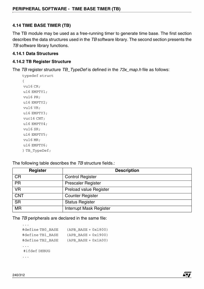
PERIPHERAL SOFTWARE - TIME BASE TIMER (TB)
4.14 TIME BASE TIMER (TB)
The TB module may be used as a free-running timer to generate time base. The first sectiondescribes the data structures used in the TB software library. The second section presents theTB software library functions.
4.14.1 Data Structures
4.14.2 TB Register Structure
The TB register structure TB_TypeDef is defined in the 73x_map.h file as follows:typedef struct
{
vu16 CR;
u16 EMPTY1;
vu16 PR;
u16 EMPTY2;
vu16 VR;
u16 EMPTY3;
vuc16 CNT;
u16 EMPTY4;
vu16 SR;
u16 EMPTY5;
vu16 MR;
u16 EMPTY6;
} TB_TypeDef;
The following table describes the TB structure fields.:
The TB peripherals are declared in the same file:...
#define TB0_BASE (APB_BASE + 0x1800)
#define TB1_BASE (APB_BASE + 0x1900)
#define TB2_BASE (APB_BASE + 0x1A00)
...
#ifdef DEBUG
...
Register DescriptionCR Control Register
PR Prescaler Register
VR Preload value RegisterCNT Counter Register
SR Status Register
MR Interrupt Mask Register
240/312
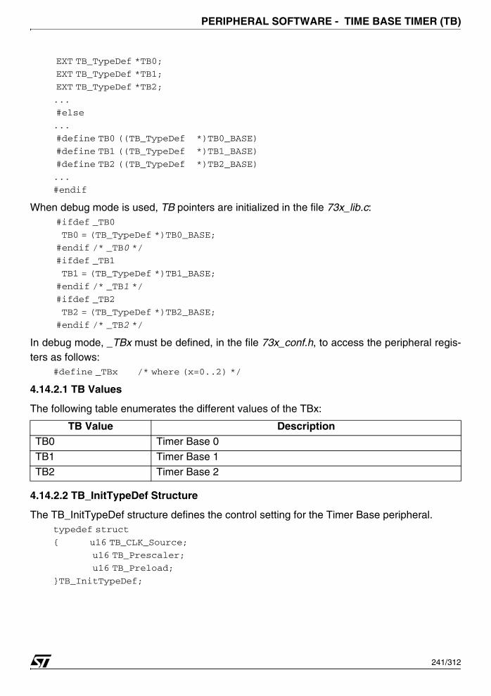
PERIPHERAL SOFTWARE - TIME BASE TIMER (TB)
EXT TB_TypeDef *TB0;
EXT TB_TypeDef *TB1;
EXT TB_TypeDef *TB2;
...
#else
...
#define TB0 ((TB_TypeDef *)TB0_BASE)
#define TB1 ((TB_TypeDef *)TB1_BASE)
#define TB2 ((TB_TypeDef *)TB2_BASE)
...
#endif
When debug mode is used, TB pointers are initialized in the file 73x_lib.c: #ifdef _TB0
TB0 = (TB_TypeDef *)TB0_BASE;
#endif /* _TB0 */
#ifdef _TB1
TB1 = (TB_TypeDef *)TB1_BASE;
#endif /* _TB1 */
#ifdef _TB2
TB2 = (TB_TypeDef *)TB2_BASE;
#endif /* _TB2 */
In debug mode, _TBx must be defined, in the file 73x_conf.h, to access the peripheral regis-ters as follows:
#define _TBx /* where (x=0..2) */
4.14.2.1 TB Values
The following table enumerates the different values of the TBx:
4.14.2.2 TB_InitTypeDef Structure
The TB_InitTypeDef structure defines the control setting for the Timer Base peripheral.typedef struct
{ u16 TB_CLK_Source;
u16 TB_Prescaler;
u16 TB_Preload;
}TB_InitTypeDef;
TB Value DescriptionTB0 Timer Base 0
TB1 Timer Base 1
TB2 Timer Base 2
241/312
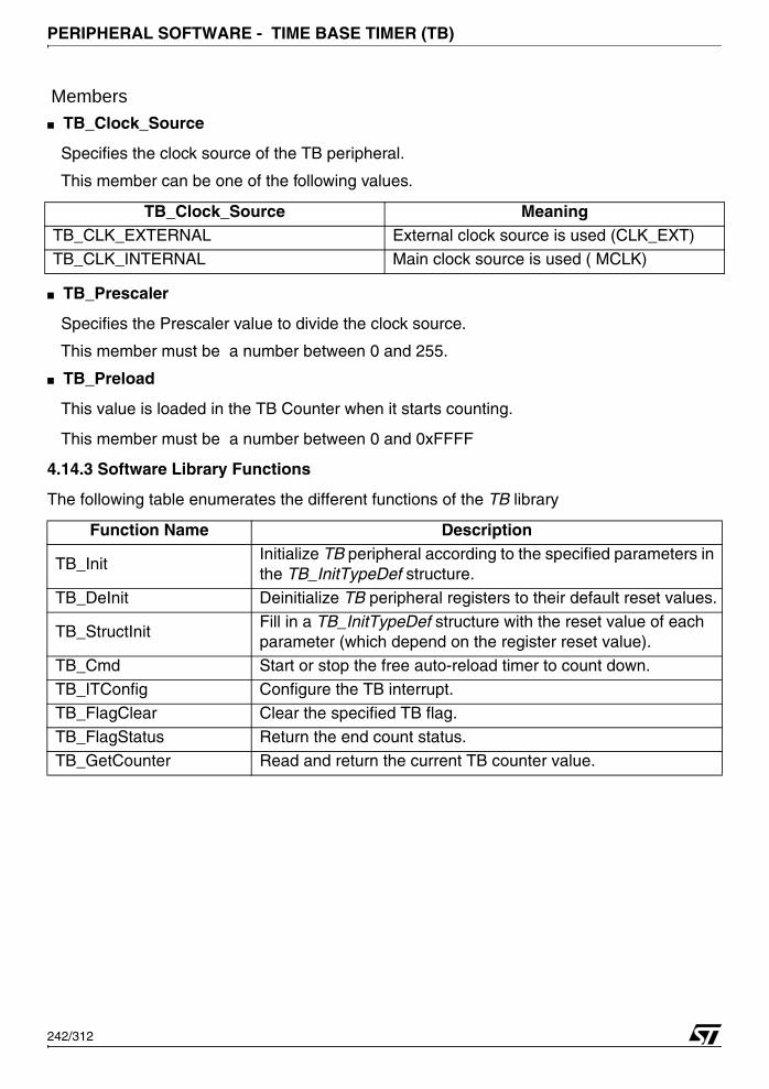
PERIPHERAL SOFTWARE - TIME BASE TIMER (TB)
Members■ TB_Clock_Source
Specifies the clock source of the TB peripheral.
This member can be one of the following values.
■ TB_Prescaler
Specifies the Prescaler value to divide the clock source.
This member must be a number between 0 and 255.
■ TB_Preload
This value is loaded in the TB Counter when it starts counting.
This member must be a number between 0 and 0xFFFF
4.14.3 Software Library Functions
The following table enumerates the different functions of the TB library
TB_Clock_Source MeaningTB_CLK_EXTERNAL External clock source is used (CLK_EXT)TB_CLK_INTERNAL Main clock source is used ( MCLK)
Function Name Description
TB_InitInitialize TB peripheral according to the specified parameters in the TB_InitTypeDef structure.
TB_DeInit Deinitialize TB peripheral registers to their default reset values.
TB_StructInitFill in a TB_InitTypeDef structure with the reset value of each parameter (which depend on the register reset value).
TB_Cmd Start or stop the free auto-reload timer to count down.TB_ITConfig Configure the TB interrupt.
TB_FlagClear Clear the specified TB flag.
TB_FlagStatus Return the end count status.
TB_GetCounter Read and return the current TB counter value.
242/312

PERIPHERAL SOFTWARE - TIME BASE TIMER (TB)
4.14.3.1 TB_Init
Example:
The following example illustrates how to configure the TB0:{
TB_InitTypeDef Init_Structure;
Init_Structure.TB_CLK_Source = TB_CLK_External;
Init_Structure.TB_Prescaler = 0x0079;
Init_Structure.TB_Preload = 0xFF00;
TB_Init (TB0,&Init_Structure);
}
or:
{
TB_InitTypeDef Init_Structure ={TB_CLK_External,0x0079,0xFF00};
TB_Init (TB0,&Init_Structure);
}
Function Name TB_Init
Function Prototypevoid TB_Init (TB_TypeDef *TBx, TB_InitTypeDef *TB_InitStruct);
Behavior Description Initializes TB peripheral according to the specified parameters in the TB_InitTypeDef structure.
Input Parameter1TBx specifies the TB to be used.
Refer to section 4.14.2.1 on page 241 for more details on the al-lowed values of this parameter.
Input Parameter2TB_InitTypeDef specifies the TB configuration parameters.Refer to section 4.14.2.2 on page 241 for more details on the al-lowed values of this parameter.
Output Parameter None
Return Parameter None
Required preconditions None
Called Functions None
243/312

PERIPHERAL SOFTWARE - TIME BASE TIMER (TB)
4.14.3.2 TB_DeInit
Example:
The following example illustrates how to deinitialize the TB0.{
...
TB_DeInit (TB0);
...
}
4.14.3.3 TB_StructInit
Example:
The following example illustrates how to initialize the TBx structure:{
TB_StructInit (&TB_InitStruct);
}
Function Name TB_DeInit
Function Prototype void TB_DeInit (TB_TypeDef *TBx);
Behavior Description Deinitialize TB peripheral registers to their default reset values.Input Parameter TBx specifies the TB to be initialized.
Output Parameter None
Return Parameter None
Required preconditions None
Called Functions None
Function Name TB_StructInit
Function Prototypevoid TB_StructInit (TB_InitTypeDef *TB_InitStruct);
Behavior DescriptionFills in a TB_InitTypeDef structure with the reset value of each pa-rameter (which depends on the register reset value).
Input Parameter TB_InitTypeDef specifies the structure to be initialized.
Output Parameter None
Return Parameter None
Required preconditions None
Called Functions None
244/312
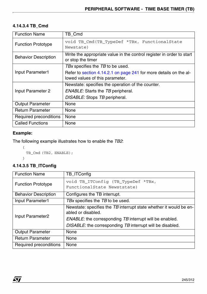
PERIPHERAL SOFTWARE - TIME BASE TIMER (TB)
4.14.3.4 TB_Cmd
Example:
The following example illustrates how to enable the TB2:{
TB_Cmd (TB2, ENABLE);
}
4.14.3.5 TB_ITConfig
Function Name TB_Cmd
Function Prototypevoid TB_Cmd(TB_TypeDef *TBx, FunctionalState Newstate)
Behavior Description Write the appropriate value in the control register in order to start or stop the timer
Input Parameter1TBx specifies the TB to be used.
Refer to section 4.14.2.1 on page 241 for more details on the al-lowed values of this parameter.
Input Parameter 2
Newstate: specifies the operation of the counter.
ENABLE: Starts the TB peripheral.
DISABLE: Stops TB peripheral.
Output Parameter NoneReturn Parameter None
Required preconditions None
Called Functions None
Function Name TB_ITConfig
Function Prototypevoid TB_ITConfig (TB_TypeDef *TBx, FunctionalState Newststate)
Behavior Description Configures the TB interrupt.
Input Parameter1 TBx specifies the TB to be used.
Input Parameter2
Newstate: specifies the TB interrupt state whether it would be en-abled or disabled.
ENABLE: the corresponding TB interrupt will be enabled.
DISABLE: the corresponding TB interrupt will be disabled.
Output Parameter NoneReturn Parameter None
Required preconditions None
245/312

PERIPHERAL SOFTWARE - TIME BASE TIMER (TB)
Example:
The following example illustrates how to enable the End Of Count Interrupt of the TB1: {
...
TB_ITConfig (TB1, ENABLE);
...
}
4.14.3.6 TB_FlagClear
Example:
The following example illustrates how to clear the end of count interrupt flag:{
TB_FlagClear (TB0);
}
Function Name TB_FlagClear
Function Prototype void TB_FlagClear (TB_TypeDef *TBx);
Behavior Description Clear the specified TB flag.
Input ParameterTBx specifies the TB to be used.
Refer to section 4.14.2.1 on page 241 for more details on the al-lowed values of this parameter.
Output Parameter None
Return Parameter None
Required preconditions None
Called Functions None
246/312
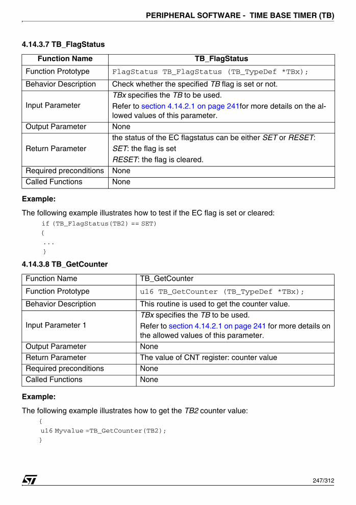
PERIPHERAL SOFTWARE - TIME BASE TIMER (TB)
4.14.3.7 TB_FlagStatus
Example:
The following example illustrates how to test if the EC flag is set or cleared: if (TB_FlagStatus(TB2) == SET) {
...
}
4.14.3.8 TB_GetCounter
Example:
The following example illustrates how to get the TB2 counter value:{
u16 Myvalue =TB_GetCounter(TB2);
}
Function Name TB_FlagStatus
Function Prototype FlagStatus TB_FlagStatus (TB_TypeDef *TBx);
Behavior Description Check whether the specified TB flag is set or not.
Input ParameterTBx specifies the TB to be used.
Refer to section 4.14.2.1 on page 241for more details on the al-lowed values of this parameter.
Output Parameter None
Return Parameterthe status of the EC flagstatus can be either SET or RESET:SET: the flag is set
RESET: the flag is cleared.
Required preconditions None
Called Functions None
Function Name TB_GetCounter
Function Prototype u16 TB_GetCounter (TB_TypeDef *TBx);
Behavior Description This routine is used to get the counter value.
Input Parameter 1TBx specifies the TB to be used.
Refer to section 4.14.2.1 on page 241 for more details on the allowed values of this parameter.
Output Parameter None
Return Parameter The value of CNT register: counter valueRequired preconditions None
Called Functions None
247/312
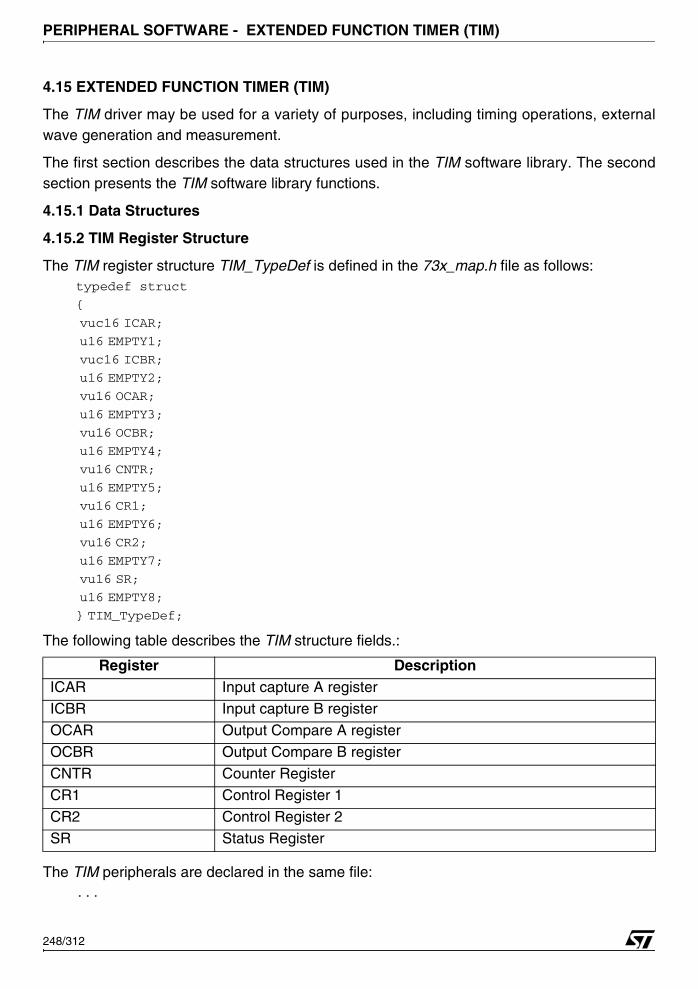
PERIPHERAL SOFTWARE - EXTENDED FUNCTION TIMER (TIM)
4.15 EXTENDED FUNCTION TIMER (TIM)
The TIM driver may be used for a variety of purposes, including timing operations, externalwave generation and measurement.
The first section describes the data structures used in the TIM software library. The secondsection presents the TIM software library functions.
4.15.1 Data Structures
4.15.2 TIM Register Structure
The TIM register structure TIM_TypeDef is defined in the 73x_map.h file as follows:typedef struct
{
vuc16 ICAR;
u16 EMPTY1;
vuc16 ICBR;
u16 EMPTY2;
vu16 OCAR;
u16 EMPTY3;
vu16 OCBR;
u16 EMPTY4;
vu16 CNTR;
u16 EMPTY5;
vu16 CR1;
u16 EMPTY6;
vu16 CR2;
u16 EMPTY7;
vu16 SR;
u16 EMPTY8;
} TIM_TypeDef;
The following table describes the TIM structure fields.:
The TIM peripherals are declared in the same file:...
Register DescriptionICAR Input capture A register
ICBR Input capture B register
OCAR Output Compare A register
OCBR Output Compare B register
CNTR Counter RegisterCR1 Control Register 1
CR2 Control Register 2
SR Status Register
248/312
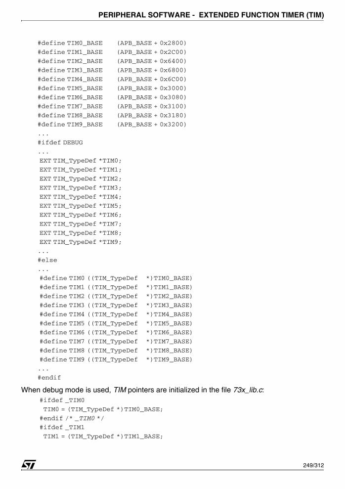
PERIPHERAL SOFTWARE - EXTENDED FUNCTION TIMER (TIM)
#define TIM0_BASE (APB_BASE + 0x2800)
#define TIM1_BASE (APB_BASE + 0x2C00)
#define TIM2_BASE (APB_BASE + 0x6400)
#define TIM3_BASE (APB_BASE + 0x6800)
#define TIM4_BASE (APB_BASE + 0x6C00)
#define TIM5_BASE (APB_BASE + 0x3000)
#define TIM6_BASE (APB_BASE + 0x3080)
#define TIM7_BASE (APB_BASE + 0x3100)
#define TIM8_BASE (APB_BASE + 0x3180)
#define TIM9_BASE (APB_BASE + 0x3200)
...
#ifdef DEBUG
...
EXT TIM_TypeDef *TIM0;
EXT TIM_TypeDef *TIM1;
EXT TIM_TypeDef *TIM2;
EXT TIM_TypeDef *TIM3;
EXT TIM_TypeDef *TIM4;
EXT TIM_TypeDef *TIM5;
EXT TIM_TypeDef *TIM6;
EXT TIM_TypeDef *TIM7;
EXT TIM_TypeDef *TIM8;
EXT TIM_TypeDef *TIM9;
...
#else
...
#define TIM0 ((TIM_TypeDef *)TIM0_BASE)
#define TIM1 ((TIM_TypeDef *)TIM1_BASE)
#define TIM2 ((TIM_TypeDef *)TIM2_BASE)
#define TIM3 ((TIM_TypeDef *)TIM3_BASE)
#define TIM4 ((TIM_TypeDef *)TIM4_BASE)
#define TIM5 ((TIM_TypeDef *)TIM5_BASE)
#define TIM6 ((TIM_TypeDef *)TIM6_BASE)
#define TIM7 ((TIM_TypeDef *)TIM7_BASE)
#define TIM8 ((TIM_TypeDef *)TIM8_BASE)
#define TIM9 ((TIM_TypeDef *)TIM9_BASE)
...
#endif
When debug mode is used, TIM pointers are initialized in the file 73x_lib.c: #ifdef _TIM0
TIM0 = (TIM_TypeDef *)TIM0_BASE;
#endif /* _TIM0 */
#ifdef _TIM1
TIM1 = (TIM_TypeDef *)TIM1_BASE;
249/312
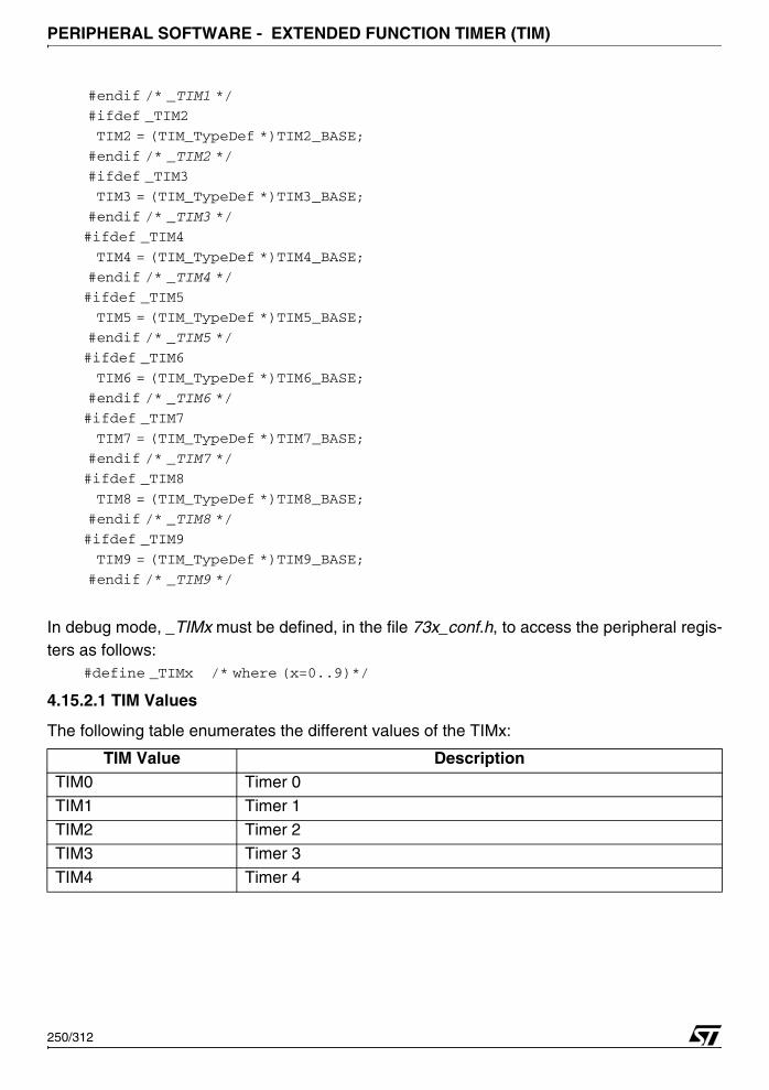
PERIPHERAL SOFTWARE - EXTENDED FUNCTION TIMER (TIM)
#endif /* _TIM1 */
#ifdef _TIM2
TIM2 = (TIM_TypeDef *)TIM2_BASE;
#endif /* _TIM2 */
#ifdef _TIM3
TIM3 = (TIM_TypeDef *)TIM3_BASE;
#endif /* _TIM3 */
#ifdef _TIM4
TIM4 = (TIM_TypeDef *)TIM4_BASE;
#endif /* _TIM4 */
#ifdef _TIM5
TIM5 = (TIM_TypeDef *)TIM5_BASE;
#endif /* _TIM5 */
#ifdef _TIM6
TIM6 = (TIM_TypeDef *)TIM6_BASE;
#endif /* _TIM6 */
#ifdef _TIM7
TIM7 = (TIM_TypeDef *)TIM7_BASE;
#endif /* _TIM7 */
#ifdef _TIM8
TIM8 = (TIM_TypeDef *)TIM8_BASE;
#endif /* _TIM8 */
#ifdef _TIM9
TIM9 = (TIM_TypeDef *)TIM9_BASE;
#endif /* _TIM9 */
In debug mode, _TIMx must be defined, in the file 73x_conf.h, to access the peripheral regis-ters as follows:
#define _TIMx /* where (x=0..9)*/
4.15.2.1 TIM Values
The following table enumerates the different values of the TIMx:
TIM Value DescriptionTIM0 Timer 0
TIM1 Timer 1
TIM2 Timer 2
TIM3 Timer 3
TIM4 Timer 4
250/312
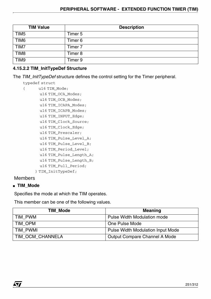
PERIPHERAL SOFTWARE - EXTENDED FUNCTION TIMER (TIM)
4.15.2.2 TIM_InitTypeDef Structure
The TIM_InitTypeDef structure defines the control setting for the Timer peripheral.typedef struct
{ u16 TIM_Mode;
u16 TIM_OCA_Modes;
u16 TIM_OCB_Modes;
u16 TIM_ICAPA_Modes;
u16 TIM_ICAPB_Modes;
u16 TIM_INPUT_Edge;
u16 TIM_Clock_Source;
u16 TIM_Clock_Edge;
u16 TIM_Prescaler;
u16 TIM_Pulse_Level_A;
u16 TIM_Pulse_Level_B;
u16 TIM_Period_Level;
u16 TIM_Pulse_Length_A;
u16 TIM_Pulse_Length_B;
u16 TIM_Full_Period;
} TIM_InitTypeDef;
Members■ TIM_Mode
Specifies the mode at which the TIM operates.
This member can be one of the following values.
TIM5 Timer 5TIM6 Timer 6
TIM7 Timer 7
TIM8 Timer 8
TIM9 Timer 9
TIM_Mode MeaningTIM_PWM Pulse Width Modulation modeTIM_OPM One Pulse Mode
TIM_PWMI Pulse Width Modulation Input Mode
TIM_OCM_CHANNELA Output Compare Channel A Mode
TIM Value Description
251/312

PERIPHERAL SOFTWARE - EXTENDED FUNCTION TIMER (TIM)
TIM_OCM_CHANNELB Output Compare Channel B ModeTIM_OCM_CHANNELAB Output Compare Channels A&B Mode
TIM_ICAP_CHANNELA Input Capture Channel A Mode
TIM_ICAP_CHANNELB Input Capture Channel B Mode
TIM_ICAP_CHANNELAB Input Capture Channel A&B Mode
TIM_Mode Meaning
252/312
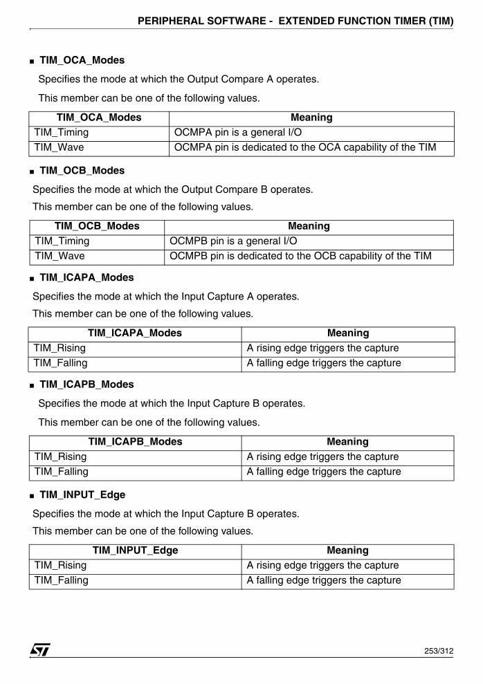
PERIPHERAL SOFTWARE - EXTENDED FUNCTION TIMER (TIM)
■ TIM_OCA_Modes
Specifies the mode at which the Output Compare A operates.
This member can be one of the following values.
■ TIM_OCB_Modes
Specifies the mode at which the Output Compare B operates.
This member can be one of the following values.
■ TIM_ICAPA_Modes
Specifies the mode at which the Input Capture A operates.
This member can be one of the following values.
■ TIM_ICAPB_Modes
Specifies the mode at which the Input Capture B operates.
This member can be one of the following values.
■ TIM_INPUT_Edge
Specifies the mode at which the Input Capture B operates.
This member can be one of the following values.
TIM_OCA_Modes MeaningTIM_Timing OCMPA pin is a general I/O
TIM_Wave OCMPA pin is dedicated to the OCA capability of the TIM
TIM_OCB_Modes MeaningTIM_Timing OCMPB pin is a general I/O
TIM_Wave OCMPB pin is dedicated to the OCB capability of the TIM
TIM_ICAPA_Modes MeaningTIM_Rising A rising edge triggers the capture
TIM_Falling A falling edge triggers the capture
TIM_ICAPB_Modes MeaningTIM_Rising A rising edge triggers the captureTIM_Falling A falling edge triggers the capture
TIM_INPUT_Edge MeaningTIM_Rising A rising edge triggers the capture
TIM_Falling A falling edge triggers the capture
253/312

PERIPHERAL SOFTWARE - EXTENDED FUNCTION TIMER (TIM)
■ TIM_Clock_Source
Specifies the clock source of the TIM peripheral.
This member can be one of the following values.
■ TIM_Clock_Edge
Specifies the which type of level transition on the reference clock will trigger the counter
This member can be one of the following values.
■ TIM_Prescaler
Specifies the Prescaler value to divide the internal clock. Timer clock will be equal to
■ TIM_Pulse_Level_A
When using PWM, OPM, OCMA or OCMAB mode, this parameter specifies the pulse level
of the signal generated on OCMPA pin. This member can be one of the following values.
■ TIM_Pulse_Level_B
TIM_Clock_Source MeaningTIM_CLK_EXTERNAL External clock is used (CLK_EXT)
TIM_CLK_INTERNAL Internal clock is used (MCLK)
TIM_ICAP_0 External clock connected to ICAPA 0 pin
TIM_ICAP_1 External clock connected to ICAPA 1 pinTIM_ICAP_2 External clock connected to ICAPA 2 pin
TIM_ICAP_3 External clock connected to ICAPA 3 pin
TIM_ICAP_4 External clock connected to ICAPA 4 pin
TIM_ICAP_5 External clock connected to ICAPA 5 pin
TIM_ICAP_6 External clock connected to ICAPA 6 pin
TIM_ICAP_7 External clock connected to ICAPA 7 pin
TIM_ICAP_8 External clock connected to ICAPA 8 pinTIM_ICAP_9 External clock connected to ICAPA 9 pin
TIM_Clock_Edge MeaningTIM_Rising A rising edge triggers the counter
TIM_Falling A falling edge triggers the counter
TIM_Pulse_Level_A MeaningTIM_High OLVLA is High Level
TIM_Low OLVLB is High Level
fCPU
Prescaler-----------------------------
254/312

PERIPHERAL SOFTWARE - EXTENDED FUNCTION TIMER (TIM)
When using OCMB or OCMAB mode, this parameter specifies the pulse level of the signal
generated on OCMPB pin. This member can be one of the following values.
TIM_Pulse_Level_B MeaningTIM_High OLVLB is High Level
TIM_Low OLVLB is High Level
255/312
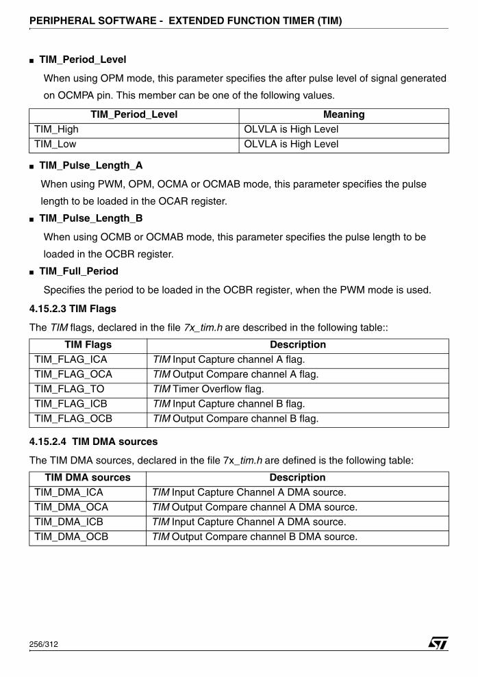
PERIPHERAL SOFTWARE - EXTENDED FUNCTION TIMER (TIM)
■ TIM_Period_Level
When using OPM mode, this parameter specifies the after pulse level of signal generated
on OCMPA pin. This member can be one of the following values.
■ TIM_Pulse_Length_A
When using PWM, OPM, OCMA or OCMAB mode, this parameter specifies the pulse
length to be loaded in the OCAR register.
■ TIM_Pulse_Length_B
When using OCMB or OCMAB mode, this parameter specifies the pulse length to be
loaded in the OCBR register.
■ TIM_Full_Period
Specifies the period to be loaded in the OCBR register, when the PWM mode is used.
4.15.2.3 TIM Flags
The TIM flags, declared in the file 7x_tim.h are described in the following table::
4.15.2.4 TIM DMA sources
The TIM DMA sources, declared in the file 7x_tim.h are defined is the following table:
TIM_Period_Level MeaningTIM_High OLVLA is High Level
TIM_Low OLVLA is High Level
TIM Flags DescriptionTIM_FLAG_ICA TIM Input Capture channel A flag.
TIM_FLAG_OCA TIM Output Compare channel A flag.TIM_FLAG_TO TIM Timer Overflow flag.
TIM_FLAG_ICB TIM Input Capture channel B flag.
TIM_FLAG_OCB TIM Output Compare channel B flag.
TIM DMA sources DescriptionTIM_DMA_ICA TIM Input Capture Channel A DMA source.
TIM_DMA_OCA TIM Output Compare channel A DMA source.
TIM_DMA_ICB TIM Input Capture Channel A DMA source.
TIM_DMA_OCB TIM Output Compare channel B DMA source.
256/312
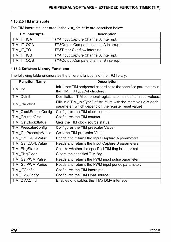
PERIPHERAL SOFTWARE - EXTENDED FUNCTION TIMER (TIM)
4.15.2.5 TIM interrupts
The TIM interrupts, declared in the 73x_tim.h file are described below:
4.15.3 Software Library Functions
The following table enumerates the different functions of the TIM library.
TIM Interrupts DescriptionTIM_IT_ICA TIM Input Capture Channel A interrupt.
TIM_IT_OCA TIM Output Compare channel A interrupt.
TIM_IT_TO TIM Timer Overflow interrupt.
TIM_IT_ICB TIM Input Capture Channel A interrupt.
TIM_IT_OCB TIM Output Compare channel B interrupt.
Function Name Description
TIM_InitInitializes TIM peripheral according to the specified parameters in the TIM_InitTypeDef structure.
TIM_DeInit Deinitializes TIM peripheral registers to their default reset values.
TIM_StructInitFills in a TIM_InitTypeDef structure with the reset value of each parameter (which depend on the register reset value)
TIM_ClockSourceConfig Configures the TIM clock source.
TIM_CounterCmd Configures the TIM counter.
TIM_GetClockStatus Gets the TIM clock source status.
TIM_PrescalerConfig Configures the TIM prescaler Value.
TIM_GetPrescalerValue Gets the TIM prescaler Value.
TIM_GetICAPAValue Reads and returns the Input Capture A parameters. TIM_GetICAPBValue Reads and returns the Input Capture B parameters.
TIM_FlagStatus Checks whether the specified TIM flag is set or not.
TIM_FlagClear Clears the specified TIM flag.
TIM_GetPWMIPulse Reads and returns the PWM input pulse parameter.
TIM_GetPWMIPeriod Reads and returns the PWM input period parameter.
TIM_ITConfig Configures the TIM interrupts.
TIM_DMAConfig Configures the TIM DMA source.TIM_DMACmd Enables or disables the TIMx DMA interface.
257/312

PERIPHERAL SOFTWARE - EXTENDED FUNCTION TIMER (TIM)
4.15.3.1 TIM_Init
Example:
The following example illustrates how to initialize all the TIM peripherals and to configure theTIM0 peripheral as Output compare mode on channel A:
{
TIM_InitTypeDef Init_Structure;
Init_Structure.TIM_Clock_Source = TIM_CLK_EXTERNAL;
Init_Structure.TIM_Clock_Edge = TIM_Rising;
Init_Structure.TIM_Prescaler = 0x0079;
Init_Structure.TIM_Mode = TIM_OCM_CHANNELA;
Init_Structure.TIM_OCA_Modes = TIM_Timing;
Init_Structure.Pulse_Level_A = TIM_High;
Init_Structure.Pulse_Length_A = 0xFF00;
TIM_Init (TIM0, &Init_Structure);
...
}
Function Name TIM_Init
Function Prototypevoid TIM_Init (TIM_TypeDef *TIMx, TIM_InitTypeDef *TIM_InitStruct);
Behavior DescriptionInitializes TIM peripheral according to the specified parameters in the TIM_InitTypeDef structure.
Input1 ParameterTIMx specifies the TIM to be used.
Refer to section 4.15.2.1 on page 250 for more details on the al-lowed values of this parameter.
Input2 ParameterTIM_InitTypeDef specifies the TIM configuration parameters.Refer to section 4.15.2.2 on page 251 for more details on the al-lowed values of this parameter.
Output Parameter None
Return Parameter None
Required preconditions None
258/312
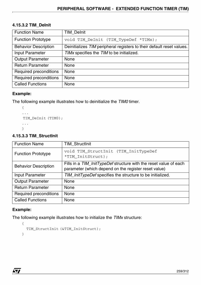
PERIPHERAL SOFTWARE - EXTENDED FUNCTION TIMER (TIM)
4.15.3.2 TIM_DeInit
Example:
The following example illustrates how to deinitialize the TIM0 timer.{
...
TIM_DeInit (TIM0);
...
}
4.15.3.3 TIM_StructInit
Example:
The following example illustrates how to initialize the TIMx structure:{
TIM_StructInit (&TIM_InitStruct);
}
Function Name TIM_DeInit
Function Prototype void TIM_DeInit (TIM_TypeDef *TIMx);
Behavior Description Deinitializes TIM peripheral registers to their default reset values.Input Parameter TIMx specifies the TIM to be initialized.
Output Parameter None
Return Parameter None
Required preconditions None
Required preconditions None
Called Functions None
Function Name TIM_StructInit
Function Prototypevoid TIM_StructInit (TIM_InitTypeDef *TIM_InitStruct);
Behavior DescriptionFills in a TIM_InitTypeDef structure with the reset value of each parameter (which depend on the register reset value)
Input Parameter TIM_InitTypeDef specifies the structure to be initialized.
Output Parameter None
Return Parameter None
Required preconditions NoneCalled Functions None
259/312
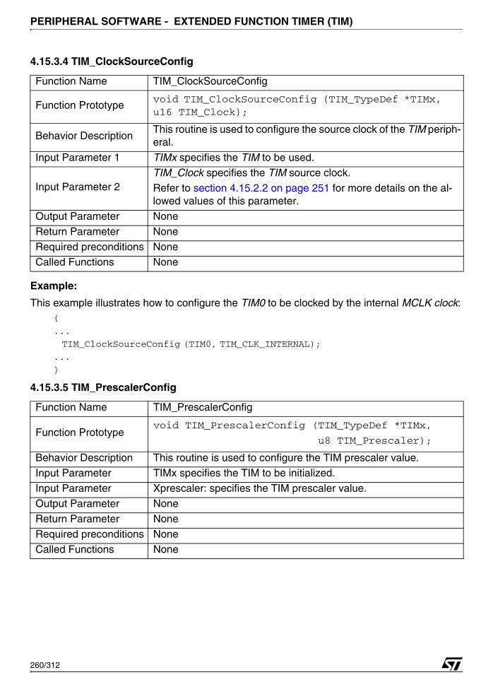
PERIPHERAL SOFTWARE - EXTENDED FUNCTION TIMER (TIM)
4.15.3.4 TIM_ClockSourceConfig
Example:
This example illustrates how to configure the TIM0 to be clocked by the internal MCLK clock:{
...
TIM_ClockSourceConfig (TIM0, TIM_CLK_INTERNAL);
...
}
4.15.3.5 TIM_PrescalerConfig
Function Name TIM_ClockSourceConfig
Function Prototypevoid TIM_ClockSourceConfig (TIM_TypeDef *TIMx, u16 TIM_Clock);
Behavior DescriptionThis routine is used to configure the source clock of the TIM periph-eral.
Input Parameter 1 TIMx specifies the TIM to be used.
Input Parameter 2TIM_Clock specifies the TIM source clock.
Refer to section 4.15.2.2 on page 251 for more details on the al-lowed values of this parameter.
Output Parameter None
Return Parameter None
Required preconditions NoneCalled Functions None
Function Name TIM_PrescalerConfig
Function Prototypevoid TIM_PrescalerConfig (TIM_TypeDef *TIMx,
u8 TIM_Prescaler);
Behavior Description This routine is used to configure the TIM prescaler value.
Input Parameter TIMx specifies the TIM to be initialized.
Input Parameter Xprescaler: specifies the TIM prescaler value.
Output Parameter None
Return Parameter None
Required preconditions NoneCalled Functions None
260/312

PERIPHERAL SOFTWARE - EXTENDED FUNCTION TIMER (TIM)
Example:
The following example illustrates how to configure the TIM3 prescaler.{
...
TIM_PrescalerConfig ( TIM3, 0x7F )
...
}
4.15.3.6 TIM_GetPrescalerValue
Example:
The following example illustrates how to get the TIM2 prescaler value.{
...
u8 MyPrescaler =TIM_GetPrescalerValue (TIM2);
...
}
4.15.3.7 TIM_GetICAPAValue
Function Name TIM_GetPrescalerValue
Function Prototype u8 TIM_GetPrescalerValue (TIM_TypeDef *TIMx)
Behavior Description This routine is used to get the Prescaler value.
Input Parameter 1TIMx specifies the TIM to be used.
Refer to section 4.15.2.1 on page 250 for more details on the al-lowed values of this parameter.
Output Parameter None
Return Parameter None
Required preconditions None
Called Functions None
Function Name TIM_GetICAPAValue
Function Prototypeu16 TIM_GetICAPAValue (TIM_TypeDef *TIMx);
Behavior Description This routine is used to get the input capture value.
Input Parameter 1 TIMx specifies the TIM to be used.
Output Parameter None
Return Parameter NoneRequired preconditions None
Called Functions None
261/312
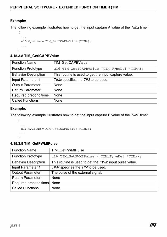
PERIPHERAL SOFTWARE - EXTENDED FUNCTION TIMER (TIM)
Example:
The following example illustrates how to get the input capture A value of the TIM2 timer{
...
u16 Myvalue = TIM_GetICAPAValue (TIM2);
...
}
4.15.3.8 TIM_GetICAPBValue
Example:
The following example illustrates how to get the input capture B value of the TIM2 timer{
...
u16 Myvalue = TIM_GetICAPBValue (TIM2);
...
}
4.15.3.9 TIM_GetPWMIPulse
Function Name TIM_GetICAPBValue
Function Prototype u16 TIM_GetICAPBValue (TIM_TypeDef *TIMx);
Behavior Description This routine is used to get the input capture value.
Input Parameter 1 TIMx specifies the TIM to be used.
Output Parameter None
Return Parameter None
Required preconditions None
Called Functions None
Function Name TIM_GetPWMIPulse
Function Prototype u16 TIM_GetPWMIPulse ( TIM_TypeDef *TIMx);
Behavior Description This routine is used to get the PWM input pulse value.
Input Parameter 1 TIMx specifies the TIM to be used.
Output Parameter The pulse of the external signal.Return Parameter None
Required preconditions None
Called Functions None
262/312

PERIPHERAL SOFTWARE - EXTENDED FUNCTION TIMER (TIM)
Example:
The following example illustrates how to get the Pulse value of the TIM3 timer{
...
u16 MyPWMPulse = TIM_GetPWMIPulse(TIM3);
...
}
4.15.3.10 TIM_GetPWMIPeriod
Example:
The following example illustrates how to get the Pulse value of the TIM3 timer{
...
u16 MyPWMIPeriod =TIM_GetPWMIPeriod(TIM3);
...
}
Function Name TIM_GetPWMIPeriod
Function Prototype u16 TIM_GetPWMIPeriod ( TIM_TypeDef *TIMx);
Behavior Description This routine is used to get the PWM input period value.
Input Parameter 1 TIMx specifies the TIM to be used.
Output Parameter The pulse of the external signal
Return Parameter None
Required preconditions None
Called Functions None
263/312
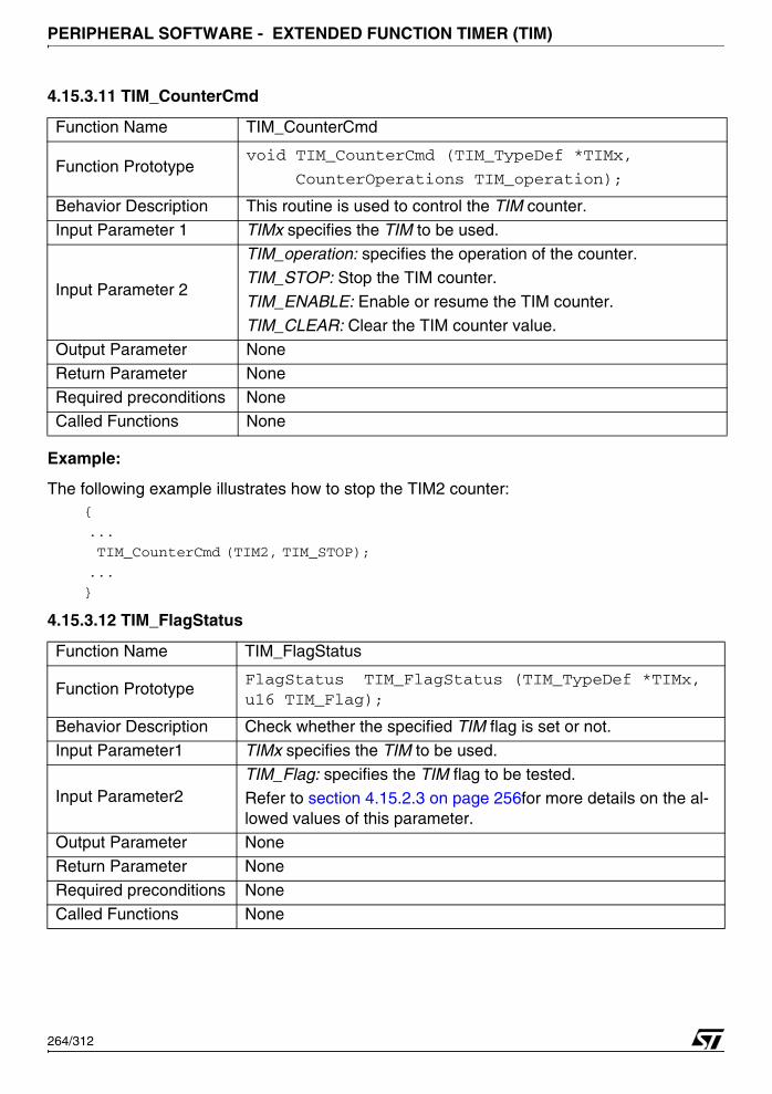
PERIPHERAL SOFTWARE - EXTENDED FUNCTION TIMER (TIM)
4.15.3.11 TIM_CounterCmd
Example:
The following example illustrates how to stop the TIM2 counter:{
...
TIM_CounterCmd (TIM2, TIM_STOP);
...
}
4.15.3.12 TIM_FlagStatus
Function Name TIM_CounterCmd
Function Prototypevoid TIM_CounterCmd (TIM_TypeDef *TIMx,
CounterOperations TIM_operation);
Behavior Description This routine is used to control the TIM counter.
Input Parameter 1 TIMx specifies the TIM to be used.
Input Parameter 2
TIM_operation: specifies the operation of the counter.TIM_STOP: Stop the TIM counter.
TIM_ENABLE: Enable or resume the TIM counter.
TIM_CLEAR: Clear the TIM counter value.
Output Parameter None
Return Parameter None
Required preconditions NoneCalled Functions None
Function Name TIM_FlagStatus
Function PrototypeFlagStatus TIM_FlagStatus (TIM_TypeDef *TIMx, u16 TIM_Flag);
Behavior Description Check whether the specified TIM flag is set or not.
Input Parameter1 TIMx specifies the TIM to be used.
Input Parameter2TIM_Flag: specifies the TIM flag to be tested.Refer to section 4.15.2.3 on page 256for more details on the al-lowed values of this parameter.
Output Parameter None
Return Parameter None
Required preconditions None
Called Functions None
264/312
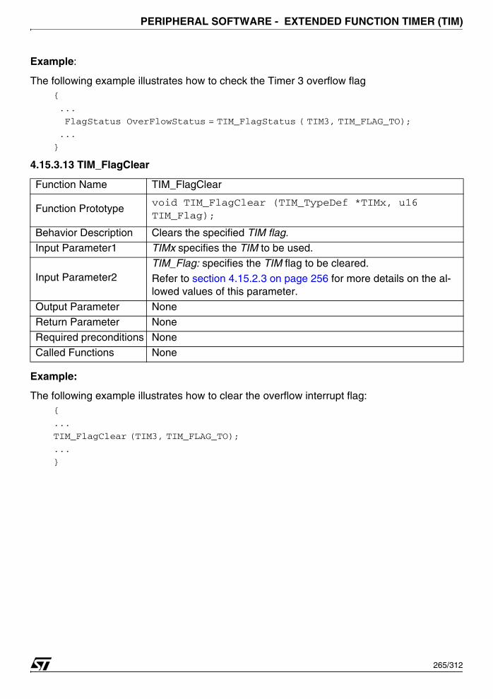
PERIPHERAL SOFTWARE - EXTENDED FUNCTION TIMER (TIM)
Example:
The following example illustrates how to check the Timer 3 overflow flag{
...
FlagStatus OverFlowStatus = TIM_FlagStatus ( TIM3, TIM_FLAG_TO);
...
}
4.15.3.13 TIM_FlagClear
Example:
The following example illustrates how to clear the overflow interrupt flag:{
...
TIM_FlagClear (TIM3, TIM_FLAG_TO);
...
}
Function Name TIM_FlagClear
Function Prototypevoid TIM_FlagClear (TIM_TypeDef *TIMx, u16 TIM_Flag);
Behavior Description Clears the specified TIM flag.Input Parameter1 TIMx specifies the TIM to be used.
Input Parameter2TIM_Flag: specifies the TIM flag to be cleared.
Refer to section 4.15.2.3 on page 256 for more details on the al-lowed values of this parameter.
Output Parameter None
Return Parameter None
Required preconditions None
Called Functions None
265/312

PERIPHERAL SOFTWARE - EXTENDED FUNCTION TIMER (TIM)
4.15.3.14 TIM_ITConfig
Example:
The following example illustrates how to enable the TIM3 overflow and input capture B inter-rupts.
{
...
TIM_ITConfig (TIM3, TIM_IT_TO | TIM_IT_ICB, ENABLE);
...
}
Function Name TIM_ITConfig
Function Prototypevoid TIM_ITConfig (TIM_TypeDef *TIMx, u16 New_IT, functionalstate Newstate)
Behavior Description This routine is used to configure the TIM interrupts.
Input Parameter 1 TIMx specifies the TIM to be used.
Input Parameter 2New_IT: specifies the TIM interrupt to be configured. The user can specify one or more TIM interrupts to be configured using the log-ical operator ‘OR’.
Input Parameter 3
Newstate: specifies the TIM interrupt state whether it would be en-abled or disabled.
ENABLE: the corresponding TIM interrupt(s) will be enabled.
DISABLE: the corresponding TIM interrupt(s) will be disabled.
Output Parameter None
Return Parameter NoneRequired preconditions None
Called Functions None
266/312
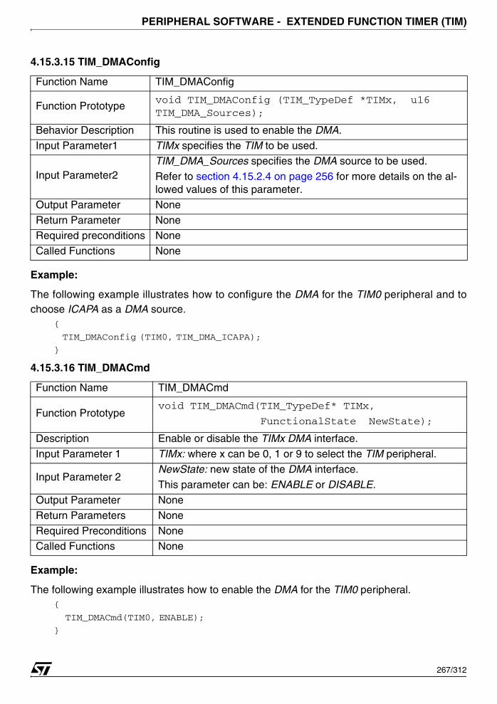
PERIPHERAL SOFTWARE - EXTENDED FUNCTION TIMER (TIM)
4.15.3.15 TIM_DMAConfig
Example:
The following example illustrates how to configure the DMA for the TIM0 peripheral and tochoose ICAPA as a DMA source.
{
TIM_DMAConfig (TIM0, TIM_DMA_ICAPA);
}
4.15.3.16 TIM_DMACmd
Example:
The following example illustrates how to enable the DMA for the TIM0 peripheral. {
TIM_DMACmd(TIM0, ENABLE);
}
Function Name TIM_DMAConfig
Function Prototypevoid TIM_DMAConfig (TIM_TypeDef *TIMx, u16 TIM_DMA_Sources);
Behavior Description This routine is used to enable the DMA.
Input Parameter1 TIMx specifies the TIM to be used.
Input Parameter2TIM_DMA_Sources specifies the DMA source to be used.
Refer to section 4.15.2.4 on page 256 for more details on the al-lowed values of this parameter.
Output Parameter None
Return Parameter NoneRequired preconditions None
Called Functions None
Function Name TIM_DMACmd
Function Prototypevoid TIM_DMACmd(TIM_TypeDef* TIMx,
FunctionalState NewState);
Description Enable or disable the TIMx DMA interface.
Input Parameter 1 TIMx: where x can be 0, 1 or 9 to select the TIM peripheral.
Input Parameter 2NewState: new state of the DMA interface.
This parameter can be: ENABLE or DISABLE.
Output Parameter None
Return Parameters None
Required Preconditions NoneCalled Functions None
267/312

PERIPHERAL SOFTWARE - UART (UART)
4.16 UART (UART)
The UART driver may be used for a variety of purposes, including mode selection, Baud rateconfiguration and 8 and 9 bit byte reception and transmission.
The first section describes the data structures used in the UART software library. The secondsection presents the UART software library functions.
4.16.1 Data Structures
4.16.1.1 UART Register Structure
The UART register structure UART_TypeDef is defined in the 73x_map.h file as follows:typedef struct
{
vu16 BRR;
u16 EMPTY1;
vu16 TxBUFR;
uv16 EMPTY2;
vuc16 RxBUFR;
u16 EMPTY3;
vu16 CR;
u16 EMPTY4;
vu16 IER;
u16 EMPTY5;
vuc16 SR;
u16 EMPTY6;
vu16 TOR;
u16 EMPTY7;
vu16 TxRSTR;
u16 EMPTY8;
vu16 RxRSTR;
u16 EMPTY9;
} UART_TypeDef;
The following table describes the UART structure fields.:
Register DescriptionBRR Baud Rate Register
TxBUFR Transmit Buffer Register
RxBUFR Receive Buffer RegisterCR Control Register
268/312
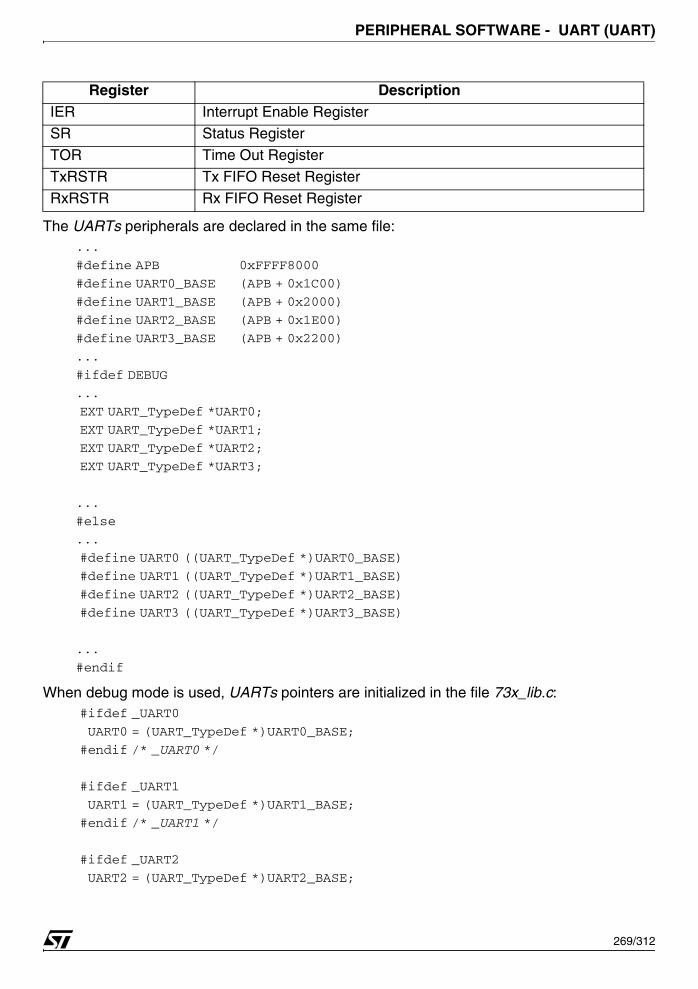
PERIPHERAL SOFTWARE - UART (UART)
The UARTs peripherals are declared in the same file:...
#define APB 0xFFFF8000
#define UART0_BASE (APB + 0x1C00)
#define UART1_BASE (APB + 0x2000)
#define UART2_BASE (APB + 0x1E00)
#define UART3_BASE (APB + 0x2200)
...
#ifdef DEBUG
...
EXT UART_TypeDef *UART0;
EXT UART_TypeDef *UART1;
EXT UART_TypeDef *UART2;
EXT UART_TypeDef *UART3;
...
#else
...
#define UART0 ((UART_TypeDef *)UART0_BASE)
#define UART1 ((UART_TypeDef *)UART1_BASE)
#define UART2 ((UART_TypeDef *)UART2_BASE)
#define UART3 ((UART_TypeDef *)UART3_BASE)
...
#endif
When debug mode is used, UARTs pointers are initialized in the file 73x_lib.c: #ifdef _UART0
UART0 = (UART_TypeDef *)UART0_BASE;
#endif /* _UART0 */
#ifdef _UART1
UART1 = (UART_TypeDef *)UART1_BASE;
#endif /* _UART1 */
#ifdef _UART2
UART2 = (UART_TypeDef *)UART2_BASE;
IER Interrupt Enable RegisterSR Status Register
TOR Time Out Register
TxRSTR Tx FIFO Reset Register
RxRSTR Rx FIFO Reset Register
Register Description
269/312
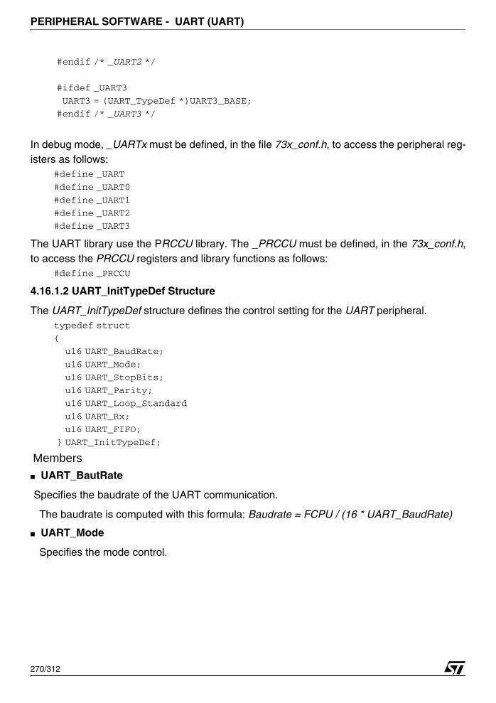
PERIPHERAL SOFTWARE - UART (UART)
#endif /* _UART2 */
#ifdef _UART3
UART3 = (UART_TypeDef *)UART3_BASE;
#endif /* _UART3 */
In debug mode, _UARTx must be defined, in the file 73x_conf.h, to access the peripheral reg-isters as follows:
#define _UART
#define _UART0
#define _UART1
#define _UART2
#define _UART3
The UART library use the PRCCU library. The _PRCCU must be defined, in the 73x_conf.h,to access the PRCCU registers and library functions as follows:
#define _PRCCU
4.16.1.2 UART_InitTypeDef Structure
The UART_InitTypeDef structure defines the control setting for the UART peripheral.typedef struct
{
u16 UART_BaudRate;
u16 UART_Mode;
u16 UART_StopBits;
u16 UART_Parity;
u16 UART_Loop_Standard
u16 UART_Rx;
u16 UART_FIFO;
} UART_InitTypeDef;
Members■ UART_BautRate
Specifies the baudrate of the UART communication.
The baudrate is computed with this formula: Baudrate = FCPU / (16 * UART_BaudRate)
■ UART_Mode
Specifies the mode control.
270/312
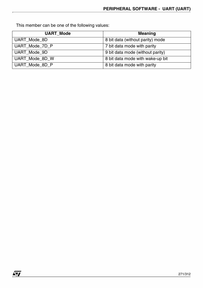
PERIPHERAL SOFTWARE - UART (UART)
This member can be one of the following values:
UART_Mode MeaningUART_Mode_8D 8 bit data (without parity) mode
UART_Mode_7D_P 7 bit data mode with parity
UART_Mode_9D 9 bit data mode (without parity)UART_Mode_8D_W 8 bit data mode with wake-up bit
UART_Mode_8D_P 8 bit data mode with parity
271/312
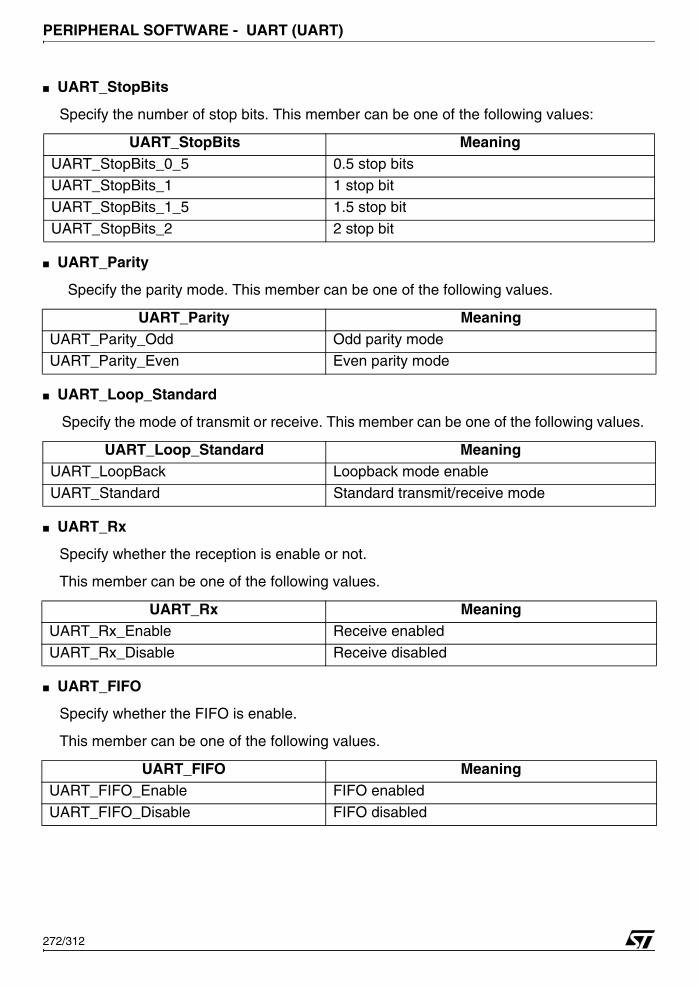
PERIPHERAL SOFTWARE - UART (UART)
■ UART_StopBits
Specify the number of stop bits. This member can be one of the following values:
■ UART_Parity
Specify the parity mode. This member can be one of the following values.
■ UART_Loop_Standard
Specify the mode of transmit or receive. This member can be one of the following values.
■ UART_Rx
Specify whether the reception is enable or not.
This member can be one of the following values.
■ UART_FIFO
Specify whether the FIFO is enable.
This member can be one of the following values.
UART_StopBits MeaningUART_StopBits_0_5 0.5 stop bitsUART_StopBits_1 1 stop bit
UART_StopBits_1_5 1.5 stop bit
UART_StopBits_2 2 stop bit
UART_Parity MeaningUART_Parity_Odd Odd parity modeUART_Parity_Even Even parity mode
UART_Loop_Standard MeaningUART_LoopBack Loopback mode enable
UART_Standard Standard transmit/receive mode
UART_Rx MeaningUART_Rx_Enable Receive enabled
UART_Rx_Disable Receive disabled
UART_FIFO MeaningUART_FIFO_Enable FIFO enabled
UART_FIFO_Disable FIFO disabled
272/312
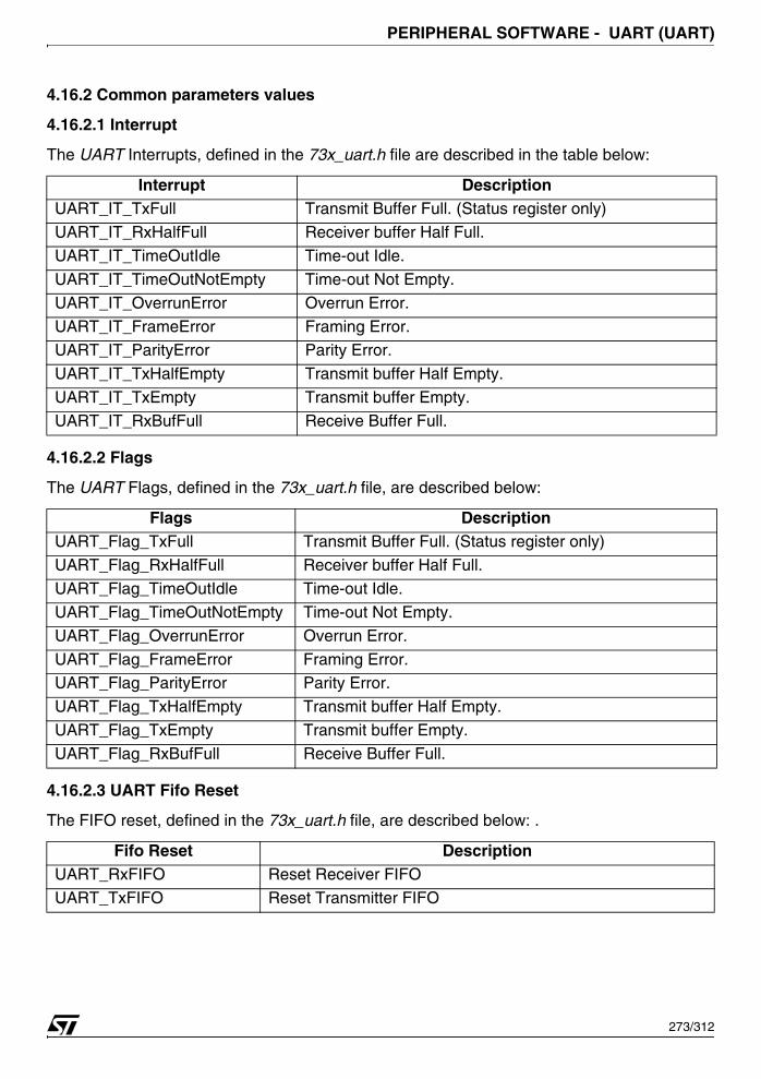
PERIPHERAL SOFTWARE - UART (UART)
4.16.2 Common parameters values
4.16.2.1 Interrupt
The UART Interrupts, defined in the 73x_uart.h file are described in the table below:
4.16.2.2 Flags
The UART Flags, defined in the 73x_uart.h file, are described below:
4.16.2.3 UART Fifo Reset
The FIFO reset, defined in the 73x_uart.h file, are described below: .
Interrupt DescriptionUART_IT_TxFull Transmit Buffer Full. (Status register only)
UART_IT_RxHalfFull Receiver buffer Half Full.
UART_IT_TimeOutIdle Time-out Idle.
UART_IT_TimeOutNotEmpty Time-out Not Empty.
UART_IT_OverrunError Overrun Error.
UART_IT_FrameError Framing Error.UART_IT_ParityError Parity Error.
UART_IT_TxHalfEmpty Transmit buffer Half Empty.
UART_IT_TxEmpty Transmit buffer Empty.
UART_IT_RxBufFull Receive Buffer Full.
Flags DescriptionUART_Flag_TxFull Transmit Buffer Full. (Status register only)
UART_Flag_RxHalfFull Receiver buffer Half Full.
UART_Flag_TimeOutIdle Time-out Idle.
UART_Flag_TimeOutNotEmpty Time-out Not Empty.
UART_Flag_OverrunError Overrun Error.
UART_Flag_FrameError Framing Error.UART_Flag_ParityError Parity Error.
UART_Flag_TxHalfEmpty Transmit buffer Half Empty.
UART_Flag_TxEmpty Transmit buffer Empty.
UART_Flag_RxBufFull Receive Buffer Full.
Fifo Reset DescriptionUART_RxFIFO Reset Receiver FIFO
UART_TxFIFO Reset Transmitter FIFO
273/312

PERIPHERAL SOFTWARE - UART (UART)
4.16.2.4 UARTx values
The following table describes the allowed values of UARTx variable.
4.16.3 Software Library Functions
The following table enumerates the different functions of the UART library.
UART values DescriptionUART0 To select UART0UART1 To select UART1
Function Name Description
UART_InitInitialize the UART peripheral according to the specified pa-rameters in the UART_InitTypeDef structure.
UART_DeInitDeinitialize the UARTx peripheral registers to their default re-set values.
UART_StructInitFill in a UART_InitTypeDef structure with the reset value of each parameter.
UART_Cmd Enable or disable UART peripheral.
UART_ByteSend Transmit single Byte of data through the UART peripheral.
UART_9BitSend Transmit 9 Bit of data through the UART peripheral.
UART_ByteBufferSendTransmit data from a user defined buffer and returns the sta-tus of transmission.
UART_9BitBufferSendTransmit 9 bits data from a user defined buffer and returns the status of transmission.
UART_StringSendTransmit a string from a user defined string and returns the status of transmission.
UART_ByteReceive Return the most recent received Byte by the UARTx. UART_9BitReceive Return the most recent received 9 bit by the UARTx.
UART_ByteBufferReceiveReceive number of data words (Byte), stores them in user de-fined area and returns the status of the reception.
UART_9BitBufferReceiveReceive number of data words (9 bits), stores them in user defined area and returns the status of the reception.
UART_StringReceiveReceive a string, stores it in a user defined area and returns the status of the reception.
UART_FlagStatus Check whether the specified UART flag is set or not.
UART_FIFOReset Reset the Rx and the Tx FIFOs of the selected UARTx.
UART_ITConfig Enable or disables the specified UARTx interrupts.
UART_SetTimeOutValue Configure the Time Out value.
UART_SetGuardTimeValue Configure the Guard Time value.
274/312
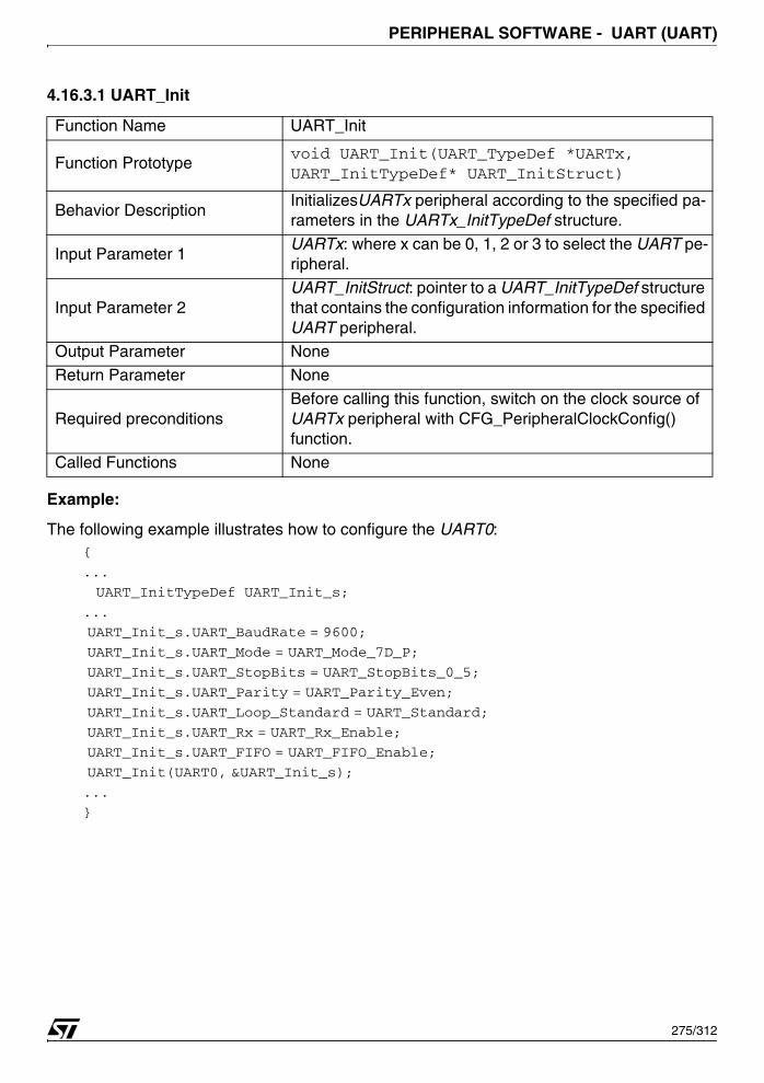
PERIPHERAL SOFTWARE - UART (UART)
4.16.3.1 UART_Init
Example:
The following example illustrates how to configure the UART0:{
...
UART_InitTypeDef UART_Init_s;
...
UART_Init_s.UART_BaudRate = 9600;
UART_Init_s.UART_Mode = UART_Mode_7D_P;
UART_Init_s.UART_StopBits = UART_StopBits_0_5;
UART_Init_s.UART_Parity = UART_Parity_Even;
UART_Init_s.UART_Loop_Standard = UART_Standard;
UART_Init_s.UART_Rx = UART_Rx_Enable;
UART_Init_s.UART_FIFO = UART_FIFO_Enable;
UART_Init(UART0, &UART_Init_s);
...
}
Function Name UART_Init
Function Prototypevoid UART_Init(UART_TypeDef *UARTx, UART_InitTypeDef* UART_InitStruct)
Behavior DescriptionInitializesUARTx peripheral according to the specified pa-rameters in the UARTx_InitTypeDef structure.
Input Parameter 1 UARTx: where x can be 0, 1, 2 or 3 to select the UART pe-ripheral.
Input Parameter 2 UART_InitStruct: pointer to a UART_InitTypeDef structure that contains the configuration information for the specified UART peripheral.
Output Parameter None
Return Parameter None
Required preconditionsBefore calling this function, switch on the clock source of UARTx peripheral with CFG_PeripheralClockConfig() function.
Called Functions None
275/312

PERIPHERAL SOFTWARE - UART (UART)
4.16.3.2 UART_DeInit
Example:
The following example illustrates how to deinitialize the UART0 peripheral:{
...
UART_DeInit(UART0);
...
}
4.16.3.3 UART_StructInit
Example:
The following example illustrates how to initialize the UART structure:{
UART_StructInit (&UART_InitStruct);
...
}
Function Name UART_DeInit
Function Prototype void UART_DeInit(UART_TypeDef *UARTx)
Behavior DescriptionDeinitialize UART peripheral control and registers to their default reset values.
Input Parameter UARTx: where x can be 0, 1, 2 or 3 to select the UART pe-ripheral.
Output Parameter None
Return Parameter None
Required preconditions None
Called Functions None
Function Name UART_StructInit
Function Prototypevoid UART_StructInit(UART_InitTypeDef* UART_InitStruct);
Behavior DescriptionFill in a UART_InitTypeDef structure with the reset value of each parameter.
Input ParameterUART_InitStruct: pointer to a UART_InitTypeDef structure which will be initialized.
Output Parameter None
Return Parameter None
Required preconditions None
Called Functions None
276/312

PERIPHERAL SOFTWARE - UART (UART)
4.16.3.4 UART_Cmd
Example:
The following example illustrates how to enable the UART0 peripheral:{
UART_Cmd(UART0, ENABLE);
...
}
4.16.3.5 UART_ByteSend
Example:
The following example illustrates how to send 0x55 via UART1:{
UART_ByteSend(UART1,0x55);
...
}
Function Name UART_Cmd
Function Prototypevoid UART_Cmd(UART_TypeDef *UARTx, FunctionalState NewState);
Behavior Description Enables or disables UART peripheral.
Input Parameter 1UARTx: where x can be 0, 1, 2 or 3 to select the UART pe-ripheral.
Input Parameter 2NewState: specifies the new state of the UART peripheral. This parameter can be: ENABLE or DISABLE.
Output Parameter None
Return Parameter None
Required preconditions None
Called Functions None
Function Name UART_ByteSend
Function Prototype void UART_ByteSend(UART_TypeDef *UARTx,vu8 data)
Behavior Description Transmits single Byte of data through the UARTx peripheral.
Input Parameter 1 UARTx: where x can be 0, 1, 2 or 3 to select the UART peripheral.Input Parameter 2 data: The data byte to send.
Output Parameter None
Return Parameter None
Required preconditions None.
Called Functions None
277/312
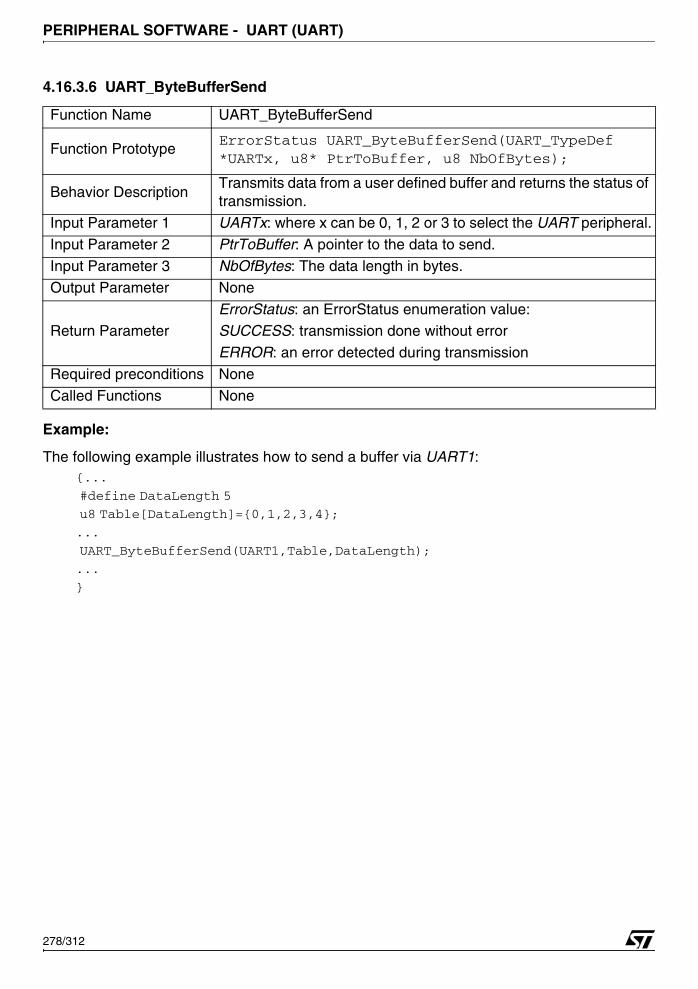
PERIPHERAL SOFTWARE - UART (UART)
4.16.3.6 UART_ByteBufferSend
Example:
The following example illustrates how to send a buffer via UART1:{...
#define DataLength 5
u8 Table[DataLength]={0,1,2,3,4};
...
UART_ByteBufferSend(UART1,Table,DataLength);
...
}
Function Name UART_ByteBufferSend
Function PrototypeErrorStatus UART_ByteBufferSend(UART_TypeDef *UARTx, u8* PtrToBuffer, u8 NbOfBytes);
Behavior DescriptionTransmits data from a user defined buffer and returns the status of transmission.
Input Parameter 1 UARTx: where x can be 0, 1, 2 or 3 to select the UART peripheral.
Input Parameter 2 PtrToBuffer: A pointer to the data to send.
Input Parameter 3 NbOfBytes: The data length in bytes.
Output Parameter None
Return ParameterErrorStatus: an ErrorStatus enumeration value:SUCCESS: transmission done without error
ERROR: an error detected during transmission
Required preconditions None
Called Functions None
278/312

PERIPHERAL SOFTWARE - UART (UART)
4.16.3.7 UART_9BitBufferSend
Example:
The following example illustrates how to send a buffer via UART1:{
#define DataLength 4
u16 Table[DataLength]={0x101,0x111,0x122,0x133};
...
UART_9BitBufferSend(UART1,Table,DataLength);
}
4.16.3.8 UART_StringSend
Function Name UART_9BitBufferSend
Function PrototypeErrorStatus UART_ByteBufferSend(UART_TypeDef *UARTx, u16* PtrToBuffer, u8 NbOfBytes);
Behavior DescriptionTransmit data (9 bit)from a user defined buffer and returns the sta-tus of transmission.
Input Parameter 1 UARTx: where x can be 0, 1, 2 or 3 to select the UART peripheral.
Input Parameter 2 PtrToBuffer: A pointer to the data to send.
Input Parameter 3 NbOfBytes: The data length in bytes.
Output Parameter None
Return ParameterErrorStatus: an ErrorStatus enumeration value:SUCCESS: transmission done without error
ERROR: an error detected during transmission
Required preconditions None
Called Functions None
Function Name UART_StringSend
Function Prototypevoid UART_StringSend(UART_TypeDef *UARTx, u8 *PtrToString)
Behavior DescriptionTransmits a string from a user defined string and returns the status of transmission.
Input Parameter 1UARTx: where x can be 0, 1, 2 or 3 to select the UART pe-ripheral.
Input Parameter 2 PtrToString: A pointer to the sting to send.Output Parameter None.
Return Parameter None.
Required preconditions None.
Called Functions None.
279/312

PERIPHERAL SOFTWARE - UART (UART)
Example:
The following example illustrates how to send string via UART1:{
u8 STRING[]="Hello World";
...
UART_StringSend(UART1,STRING);
UART_StringSend(UART1,(u8 *)"Hello World");
...
}
4.16.3.9 UART_ByteReceive
Example:
The following example illustrates how to receive byte via UART 1:{
...
u8 bRxData =UART_ByteReceive(UART1);
...
}
4.16.3.10 UART_9BitReceive
Function Name UART_ByteReceive
Function Prototype u8 UART_ByteReceive(UART_TypeDef *UARTx)
Behavior Description Returns the most recent received Byte by the UARTx peripheral.
Input Parameter 1 UARTx: where x can be 0, 1, 2 or 3 to select the UART peripheral.Output Parameter None
Return Parameter The received data.
Required preconditions None
Called Functions None
Function Name UART_9BitReceive
Function Prototype u16 UART_9BitReceive(UART_TypeDef *UARTx)
Behavior Description Returns the most recent received 9 bits by the UARTx peripheral.
Input Parameter 1 UARTx: where x can be 0.. 3 to select the UART peripheral.
Output Parameter None
Return Parameter The received data.Required preconditions None.
Called Functions None
280/312
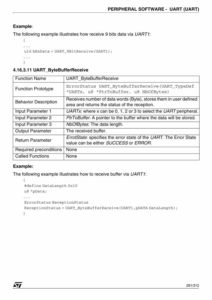
PERIPHERAL SOFTWARE - UART (UART)
Example:
The following example illustrates how receive 9 bits data via UART1:{
...
u16 bRxData = UART_9BitReceive(UART1);
...
}
4.16.3.11 UART_ByteBufferReceive
Example:
The following example illustrates how to receive buffer via UART1:{
#define DataLength 0x10
u8 *pData;
...
ErrorStatus ReceptionStatus
ReceptionStatus = UART_ByteBufferReceive(UART1,pDATA DataLength);
}
Function Name UART_ByteBufferReceive
Function PrototypeErrorStatus UART_ByteBufferReceive(UART_TypeDef *UARTx, u8 *PtrToBuffer, u8 NbOfBytes)
Behavior DescriptionReceives number of data words (Byte), stores them in user defined area and returns the status of the reception.
Input Parameter 1 UARTx: where x can be 0, 1, 2 or 3 to select the UART peripheral.
Input Parameter 2 PtrToBuffer: A pointer to the buffer where the data will be stored.
Input Parameter 3 NbOfBytes: The data length.
Output Parameter The received buffer.
Return ParameterErrotState: specifies the error state of the UART. The Error State value can be either SUCCESS or ERROR.
Required preconditions None
Called Functions None
281/312

PERIPHERAL SOFTWARE - UART (UART)
4.16.3.12 UART_9BitBufferReceive
Example:
The following example illustrates how to receive 9 bit buffer via UART1:{
#define DataLength 0x15
ErrorStatus ReceptionStatus;
u16 *pDATA;
...
ReceptionStatus = UART_9BitBufferReceive(UART1,pDATA,DataLength);
...
}
Function Name UART_9BitBufferReceive
Function Prototype
ErrorStatus UART_9BitBufferReceive(
UART_TypeDef * UARTTx,
u16 *PtrToBuffer, u8 NbOfBytes)
Behavior DescriptionReceives number of data words (9 bits), stores them in user de-fined area and returns the status of the reception.
Input Parameter 1 UARTx: where x can be 0, 1, 2 or 3 to select the UART peripheral.
Input Parameter 2 PtrToBuffer: A pointer to the buffer where the data will be stored.Input Parameter 2 NbOfBytes: The data length.
Output Parameter The received buffer.
Return ParameterErrotState: specifies the error state of the UART. The Error State value can be either SUCCESS or ERROR.
Required preconditions None.
Called Functions None
282/312
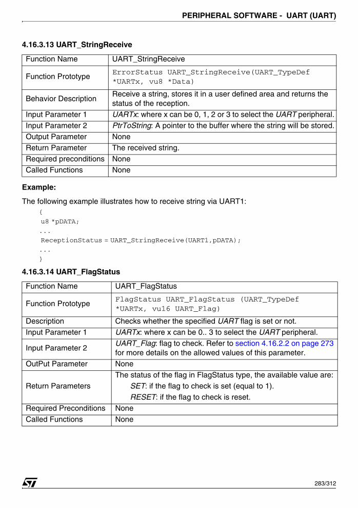
PERIPHERAL SOFTWARE - UART (UART)
4.16.3.13 UART_StringReceive
Example:
The following example illustrates how to receive string via UART1:{
u8 *pDATA;
...
ReceptionStatus = UART_StringReceive(UART1,pDATA);
...
}
4.16.3.14 UART_FlagStatus
Function Name UART_StringReceive
Function PrototypeErrorStatus UART_StringReceive(UART_TypeDef *UARTx, vu8 *Data)
Behavior DescriptionReceive a string, stores it in a user defined area and returns the status of the reception.
Input Parameter 1 UARTx: where x can be 0, 1, 2 or 3 to select the UART peripheral.
Input Parameter 2 PtrToString: A pointer to the buffer where the string will be stored.
Output Parameter None
Return Parameter The received string.
Required preconditions NoneCalled Functions None
Function Name UART_FlagStatus
Function PrototypeFlagStatus UART_FlagStatus (UART_TypeDef *UARTx, vu16 UART_Flag)
Description Checks whether the specified UART flag is set or not.
Input Parameter 1 UARTx: where x can be 0.. 3 to select the UART peripheral.
Input Parameter 2UART_Flag: flag to check. Refer to section 4.16.2.2 on page 273 for more details on the allowed values of this parameter.
OutPut Parameter None
Return ParametersThe status of the flag in FlagStatus type, the available value are: SET: if the flag to check is set (equal to 1).
RESET: if the flag to check is reset.
Required Preconditions None
Called Functions None
283/312
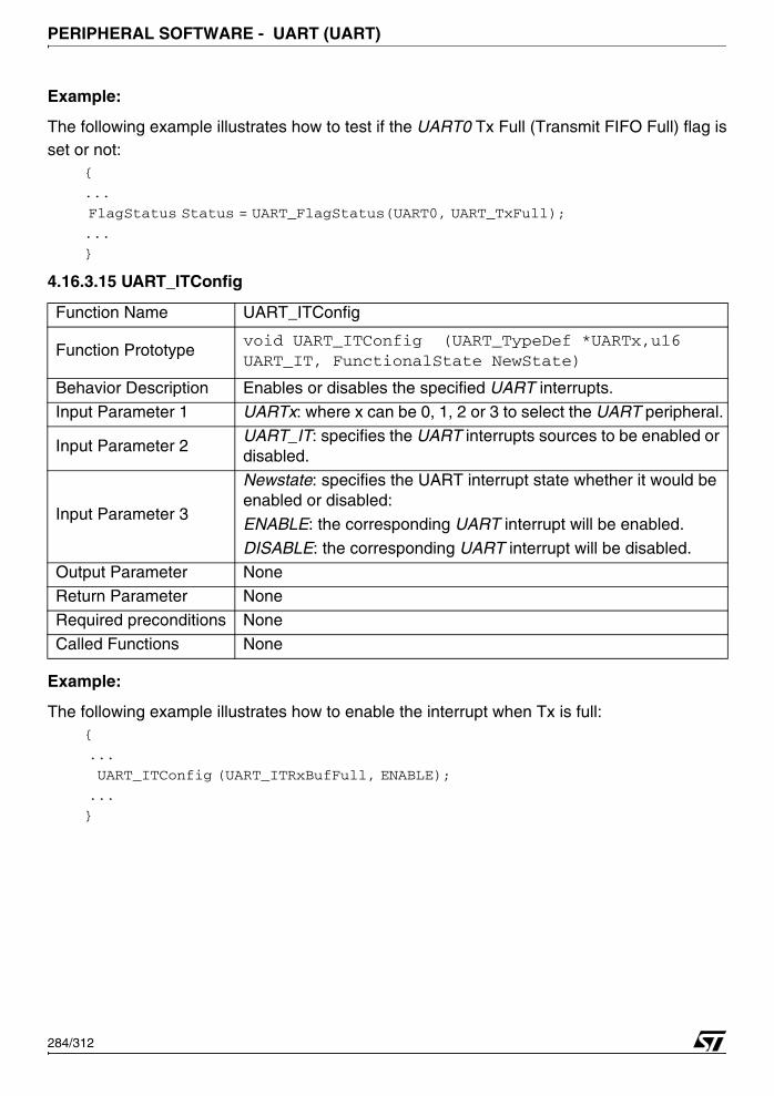
PERIPHERAL SOFTWARE - UART (UART)
Example:
The following example illustrates how to test if the UART0 Tx Full (Transmit FIFO Full) flag isset or not:
{
...
FlagStatus Status = UART_FlagStatus(UART0, UART_TxFull);
...
}
4.16.3.15 UART_ITConfig
Example:
The following example illustrates how to enable the interrupt when Tx is full:{
...
UART_ITConfig (UART_ITRxBufFull, ENABLE);
...
}
Function Name UART_ITConfig
Function Prototypevoid UART_ITConfig (UART_TypeDef *UARTx,u16 UART_IT, FunctionalState NewState)
Behavior Description Enables or disables the specified UART interrupts.
Input Parameter 1 UARTx: where x can be 0, 1, 2 or 3 to select the UART peripheral.
Input Parameter 2UART_IT: specifies the UART interrupts sources to be enabled or disabled.
Input Parameter 3
Newstate: specifies the UART interrupt state whether it would be enabled or disabled:
ENABLE: the corresponding UART interrupt will be enabled.
DISABLE: the corresponding UART interrupt will be disabled.Output Parameter None
Return Parameter None
Required preconditions None
Called Functions None
284/312
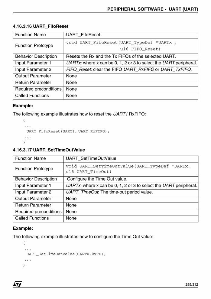
PERIPHERAL SOFTWARE - UART (UART)
4.16.3.16 UART_FifoReset
Example:
The following example illustrates how to reset the UART1 RxFIFO:{
...
UART_FifoReset(UART1, UART_RxFIFO);
...
}
4.16.3.17 UART_SetTimeOutValue
Example:
The following example illustrates how to configure the Time Out value:{
...
UART_SetTimeOutValue(UART0,0xFF);
...
}
Function Name UART_FifoReset
Function Prototypevoid UART_FifoReset(UART_TypeDef *UARTx ,
u16 FIFO_Reset)
Behavior Description Resets the Rx and the Tx FIFOs of the selected UART.
Input Parameter 1 UARTx: where x can be 0, 1, 2 or 3 to select the UART peripheral.
Input Parameter 2 FIFO_Reset: clear the FIFO UART_RxFIFO or UART_TxFIFO.Output Parameter None
Return Parameter None
Required preconditions None
Called Functions None
Function Name UART_SetTimeOutValue
Function Prototypevoid UART_SetTimeOutValue(UART_TypeDef *UARTx, u16 UART_TimeOut)
Behavior Description Configure the Time Out value.
Input Parameter 1 UARTx: where x can be 0, 1, 2 or 3 to select the UART peripheral.
Input Parameter 2 UART_TimeOut: The time-out period value.
Output Parameter None
Return Parameter None
Required preconditions NoneCalled Functions None
285/312
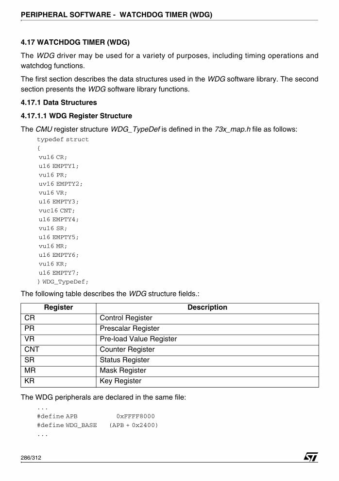
PERIPHERAL SOFTWARE - WATCHDOG TIMER (WDG)
4.17 WATCHDOG TIMER (WDG)
The WDG driver may be used for a variety of purposes, including timing operations andwatchdog functions.
The first section describes the data structures used in the WDG software library. The secondsection presents the WDG software library functions.
4.17.1 Data Structures
4.17.1.1 WDG Register Structure
The CMU register structure WDG_TypeDef is defined in the 73x_map.h file as follows:typedef struct
{
vu16 CR;
u16 EMPTY1;
vu16 PR;
uv16 EMPTY2;
vu16 VR;
u16 EMPTY3;
vuc16 CNT;
u16 EMPTY4;
vu16 SR;
u16 EMPTY5;
vu16 MR;
u16 EMPTY6;
vu16 KR;
u16 EMPTY7;
} WDG_TypeDef;
The following table describes the WDG structure fields.:
The WDG peripherals are declared in the same file:...
#define APB 0xFFFF8000
#define WDG_BASE (APB + 0x2400)
...
Register DescriptionCR Control Register
PR Prescalar Register
VR Pre-load Value Register
CNT Counter Register
SR Status RegisterMR Mask Register
KR Key Register
286/312
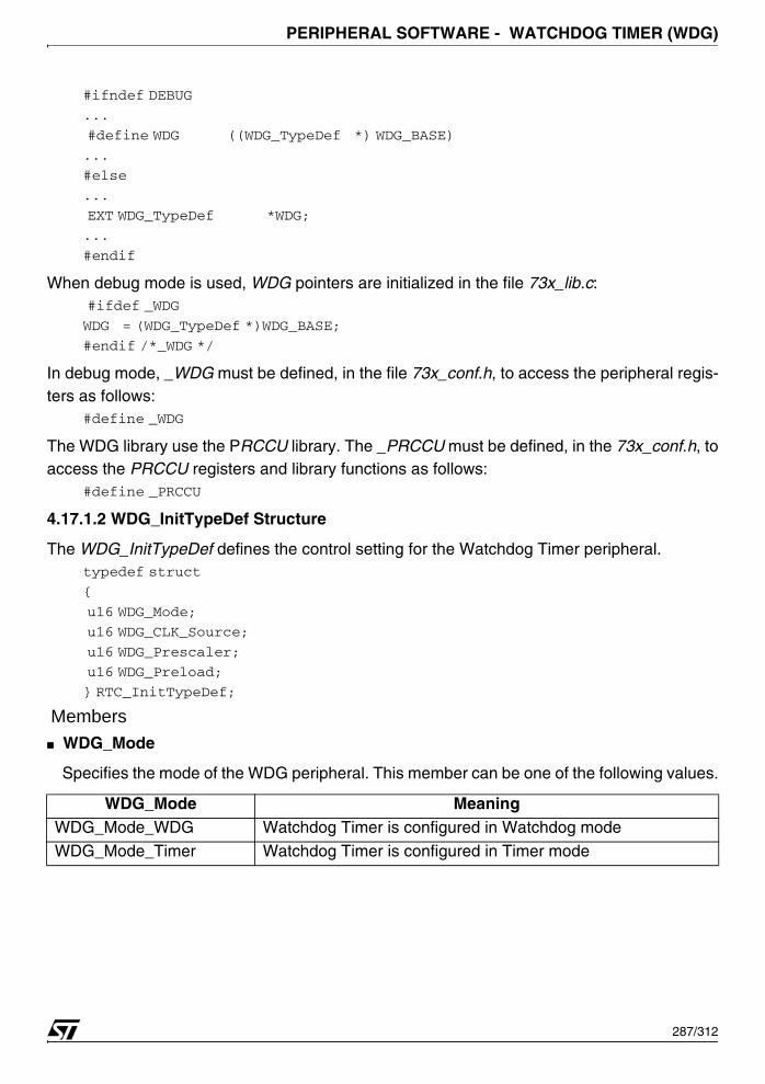
PERIPHERAL SOFTWARE - WATCHDOG TIMER (WDG)
#ifndef DEBUG
...
#define WDG ((WDG_TypeDef *) WDG_BASE)
...
#else
...
EXT WDG_TypeDef *WDG;
...
#endif
When debug mode is used, WDG pointers are initialized in the file 73x_lib.c: #ifdef _WDG
WDG = (WDG_TypeDef *)WDG_BASE;
#endif /*_WDG */
In debug mode, _WDG must be defined, in the file 73x_conf.h, to access the peripheral regis-ters as follows:
#define _WDG
The WDG library use the PRCCU library. The _PRCCU must be defined, in the 73x_conf.h, toaccess the PRCCU registers and library functions as follows:
#define _PRCCU
4.17.1.2 WDG_InitTypeDef Structure
The WDG_InitTypeDef defines the control setting for the Watchdog Timer peripheral.typedef struct
{
u16 WDG_Mode;
u16 WDG_CLK_Source;
u16 WDG_Prescaler;
u16 WDG_Preload;
} RTC_InitTypeDef;
Members■ WDG_Mode
Specifies the mode of the WDG peripheral. This member can be one of the following values.
WDG_Mode MeaningWDG_Mode_WDG Watchdog Timer is configured in Watchdog mode
WDG_Mode_Timer Watchdog Timer is configured in Timer mode
287/312

PERIPHERAL SOFTWARE - WATCHDOG TIMER (WDG)
■ WDG_Clock_Source
Specifies the clock source of the WDG peripheral.
This member can be one of the following values.
■ WDG_Prescaler
Specifies the Prescaler value to divide the clock source.
This member must be a number between 0 and 255.
■ WDG_Preload
This value is loaded in the WDG Counter when it starts counting.
This member must be a number between 0 and 0xFFFF.
4.17.2 Software Library Functions
The following table enumerates the different functions of the WDG library.
WDG_Clock_Source MeaningWDG_CLK_EXTERNAL External clock source is used (CLK_EXT)
WDG_CLK_INTERNAL Main clock source is used (MCLK)
Function Name Description
WDG_InitInitializes WDG peripheral according to the specified parame-ters in the WDG_InitTypeDef structure.
WDG_DeInitDeinitializes WDG peripheral registers to their default reset val-ues.
WDG_StructInitFills in a WDG_InitTypeDef structure with the reset value of each parameter.
WDG_Cmd Enables or disables WDG peripheral.
WDG_ITConfig Enable or disable the end count interrupt
WDG_FlagClear Clears the end count flag
WDG_FlagStatus Checks whether the end of counter flag is set or not
WDG_GetCounterValue To get the current counter value.
288/312
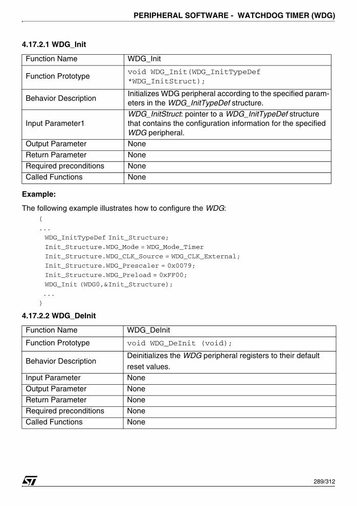
PERIPHERAL SOFTWARE - WATCHDOG TIMER (WDG)
4.17.2.1 WDG_Init
Example:
The following example illustrates how to configure the WDG:{
...
WDG_InitTypeDef Init_Structure;
Init_Structure.WDG_Mode = WDG_Mode_Timer
Init_Structure.WDG_CLK_Source = WDG_CLK_External;
Init_Structure.WDG_Prescaler = 0x0079;
Init_Structure.WDG_Preload = 0xFF00;
WDG_Init (WDG0,&Init_Structure);
...
}
4.17.2.2 WDG_DeInit
Function Name WDG_Init
Function Prototypevoid WDG_Init(WDG_InitTypeDef *WDG_InitStruct);
Behavior Description Initializes WDG peripheral according to the specified param-eters in the WDG_InitTypeDef structure.
Input Parameter1WDG_InitStruct: pointer to a WDG_InitTypeDef structure that contains the configuration information for the specified WDG peripheral.
Output Parameter None
Return Parameter None
Required preconditions None
Called Functions None
Function Name WDG_DeInit
Function Prototype void WDG_DeInit (void);
Behavior DescriptionDeinitializes the WDG peripheral registers to their default
reset values.
Input Parameter None
Output Parameter NoneReturn Parameter None
Required preconditions None
Called Functions None
289/312

PERIPHERAL SOFTWARE - WATCHDOG TIMER (WDG)
Example:
The following example illustrates how to deinitialize the WDG peripheral:{
...
WDG_DeInit();...
}
4.17.2.3 WDG_StructInit
Example:
The following example illustrates how to initialize the WDG structure:{
...
WDG_StructInit (&WDG_InitStruct);
...
}
Function Name WDG_StructInit
Function Prototypevoid WDG_StructInit (WDG_InitTypeDef *WDG_InitStruct);
Behavior DescriptionFills in a WDG_InitTypeDef structure with the reset value of
each parameter.
Input ParameterWDG_InitStruct: pointer to a WDG_InitTypeDef structure which will be initialized.
Output Parameter None
Return Parameter None
Required preconditions None
Called Functions None
290/312
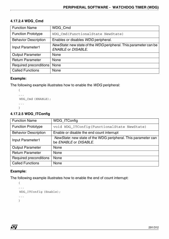
PERIPHERAL SOFTWARE - WATCHDOG TIMER (WDG)
4.17.2.4 WDG_Cmd
Example:
The following example illustrates how to enable the WDG peripheral:{
...
WDG_Cmd (ENABLE);
...
}
4.17.2.5 WDG_ITConfig
Example:
The following example illustrates how to enable the end of count interrupt:{
...
WDG_ITConfig (Enable);
...
}
Function Name WDG_Cmd
Function Prototype WDG_Cmd(FunctionalState NewState)
Behavior Description Enables or disables WDG peripheral.
Input Parameter1NewState: new state of the WDG peripheral. This parameter can be ENABLE or DISABLE.
Output Parameter None
Return Parameter None
Required preconditions NoneCalled Functions None
Function Name WDG_ITConfig
Function Prototype void WDG_ITConfig(FunctionalState NewState)
Behavior Description Enable or disable the end count interrupt
Input Parameter1 NewState: new state of the WDG peripheral. This parameter can be ENABLE or DISABLE.
Output Parameter NoneReturn Parameter None
Required preconditions None
Called Functions None
291/312
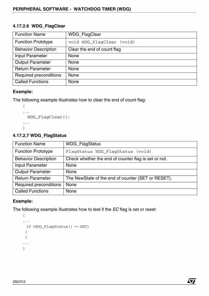
PERIPHERAL SOFTWARE - WATCHDOG TIMER (WDG)
4.17.2.6 WDG_FlagClear
Example:
The following example illustrates how to clear the end of count flag:{
...
WDG_FlagClear();...
}
4.17.2.7 WDG_FlagStatus
Example:
The following example illustrates how to test if the EC flag is set or reset:{
...
if (WDG_FlagStatus() == SET)
{
}
...
}
Function Name WDG_FlagClear
Function Prototype void WDG_FlagClear (void)
Behavior Description Clear the end of count flag
Input Parameter None
Output Parameter None
Return Parameter NoneRequired preconditions None
Called Functions None
Function Name WDG_FlagStatus
Function Prototype FlagStatus WDG_FlagStatus (void)
Behavior Description Check whether the end of counter flag is set or not.Input Parameter None
Output Parameter None
Return Parameter The NewState of the end of counter (SET or RESET).
Required preconditions None
Called Functions None
292/312
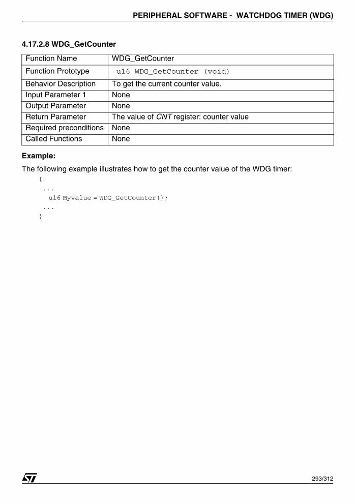
PERIPHERAL SOFTWARE - WATCHDOG TIMER (WDG)
4.17.2.8 WDG_GetCounter
Example:
The following example illustrates how to get the counter value of the WDG timer:{
...
u16 Myvalue = WDG_GetCounter();
...
}
Function Name WDG_GetCounter
Function Prototype u16 WDG_GetCounter (void)
Behavior Description To get the current counter value.
Input Parameter 1 None
Output Parameter None
Return Parameter The value of CNT register: counter valueRequired preconditions None
Called Functions None
293/312
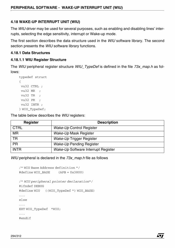
PERIPHERAL SOFTWARE - WAKE-UP INTERRUPT UNIT (WIU)
4.18 WAKE-UP INTERRUPT UNIT (WIU)
The WIU driver may be used for several purposes, such as enabling and disabling lines’ inter-rupts, selecting the edge sensitivity, interrupt or Wake-up mode.
The first section describes the data structure used in the WIU software library. The secondsection presents the WIU software library functions.
4.18.1 Data Structures
4.18.1.1 WIU Register Structure
The WIU peripheral register structure WIU_TypeDef is defined in the file 73x_map.h as fol-lows:
typedef struct
{
vu32 CTRL ;
vu32 MR ;
vu32 TR ;
vu32 PR ;
vu32 INTR ;
} WIU_TypeDef;
The table below describes the WIU registers:
WIU peripheral is declared in the 73x_map.h file as follows
/* WIU Base Address definition */
#define WIU_BASE (APB + 0x3800)
/* WIU peripheral pointer declaration*/
#ifndef DEBUG
#define WIU ((WIU_TypeDef *) WIU_BASE)
...
else
...
EXT WIU_TypeDef *WIU;
...
#endif
Register DescriptionCTRL Wake-Up Control Register
MR Wake-Up Mask Register
TR Wake-Up Trigger Register
PR Wake-Up Pending Register INTR Wake-Up Software Interrupt Register
294/312

PERIPHERAL SOFTWARE - WAKE-UP INTERRUPT UNIT (WIU)
When debug mode is used, WIU pointer is initialized in 73x_lib.c file: #ifdef _WIU
WIU = (WIU_TypeDef *)WIU_BASE;
#endif /* _WIU */
In debug mode, _WIU must be defined, in 73x_conf.h file, to include the WIU library #define _WIU
Some CFG registers are used in the main application to enable the Clock of the peripheral, inthe file 73x_conf.h, to make the CFG accessible, user must define:
#define _CFG
4.18.1.2 WIU_InitTypeDef Structure
The WIU_InitTypeDef structure defines the control setting for the WIU cell.typedef struct
{
u8 WIU_Mode;
u8 WIU_TriggerEdge;
u32 WIU_Line;
}WIU_InitTypeDef;
Members■ WIU_Mode
Specifies the WIU mode to be used.
This member can be one of the following values.
WIU_Mode Description
WIU_Mode_WakeUp Wake-up lines will be used to Wake Up the system from the STOP mode.
WIU_Mode_InterruptWake-up lines will be used to generate an interrupt on the WIU channel.
WIU_Mode_WakeUpInterrupt Wake-up lines will be used to Wake Up the system from the STOP mode and generate an interrupt on the WIU channel.
WIU_Mode_SWInterrupt Wake-up lines will be used to generate software interrupt on the WIU channel.
295/312
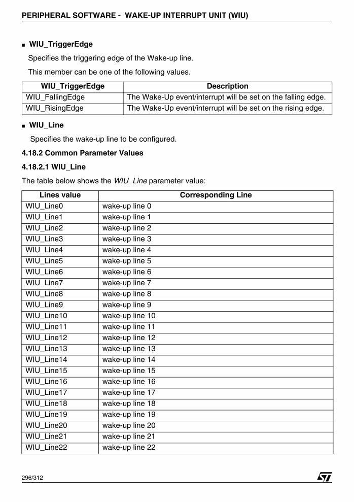
PERIPHERAL SOFTWARE - WAKE-UP INTERRUPT UNIT (WIU)
■ WIU_TriggerEdge
Specifies the triggering edge of the Wake-up line.
This member can be one of the following values.
■ WIU_Line
Specifies the wake-up line to be configured.
4.18.2 Common Parameter Values
4.18.2.1 WIU_Line
The table below shows the WIU_Line parameter value:
WIU_TriggerEdge DescriptionWIU_FallingEdge The Wake-Up event/interrupt will be set on the falling edge.
WIU_RisingEdge The Wake-Up event/interrupt will be set on the rising edge.
Lines value Corresponding LineWIU_Line0 wake-up line 0
WIU_Line1 wake-up line 1
WIU_Line2 wake-up line 2WIU_Line3 wake-up line 3
WIU_Line4 wake-up line 4
WIU_Line5 wake-up line 5
WIU_Line6 wake-up line 6
WIU_Line7 wake-up line 7
WIU_Line8 wake-up line 8
WIU_Line9 wake-up line 9WIU_Line10 wake-up line 10
WIU_Line11 wake-up line 11
WIU_Line12 wake-up line 12
WIU_Line13 wake-up line 13
WIU_Line14 wake-up line 14
WIU_Line15 wake-up line 15WIU_Line16 wake-up line 16
WIU_Line17 wake-up line 17
WIU_Line18 wake-up line 18
WIU_Line19 wake-up line 19
WIU_Line20 wake-up line 20
WIU_Line21 wake-up line 21
WIU_Line22 wake-up line 22
296/312
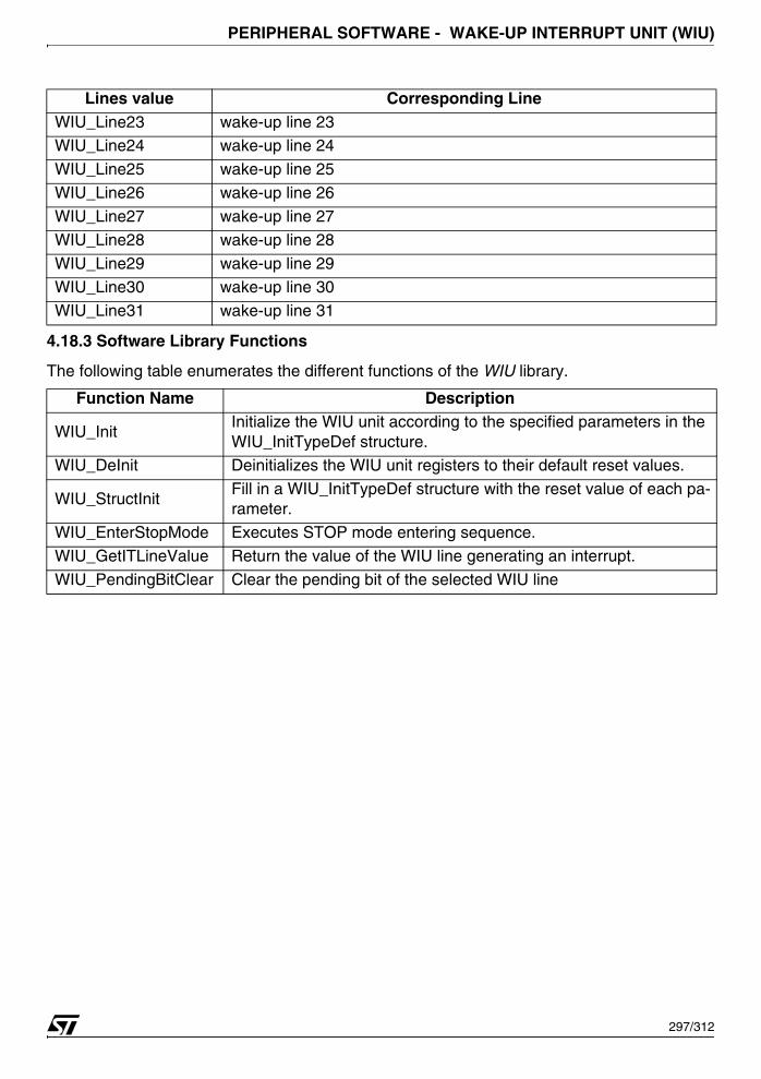
PERIPHERAL SOFTWARE - WAKE-UP INTERRUPT UNIT (WIU)
4.18.3 Software Library Functions
The following table enumerates the different functions of the WIU library.
WIU_Line23 wake-up line 23WIU_Line24 wake-up line 24
WIU_Line25 wake-up line 25
WIU_Line26 wake-up line 26
WIU_Line27 wake-up line 27
WIU_Line28 wake-up line 28
WIU_Line29 wake-up line 29WIU_Line30 wake-up line 30
WIU_Line31 wake-up line 31
Function Name Description
WIU_InitInitialize the WIU unit according to the specified parameters in the WIU_InitTypeDef structure.
WIU_DeInit Deinitializes the WIU unit registers to their default reset values.
WIU_StructInitFill in a WIU_InitTypeDef structure with the reset value of each pa-rameter.
WIU_EnterStopMode Executes STOP mode entering sequence.
WIU_GetITLineValue Return the value of the WIU line generating an interrupt.
WIU_PendingBitClear Clear the pending bit of the selected WIU line
Lines value Corresponding Line
297/312
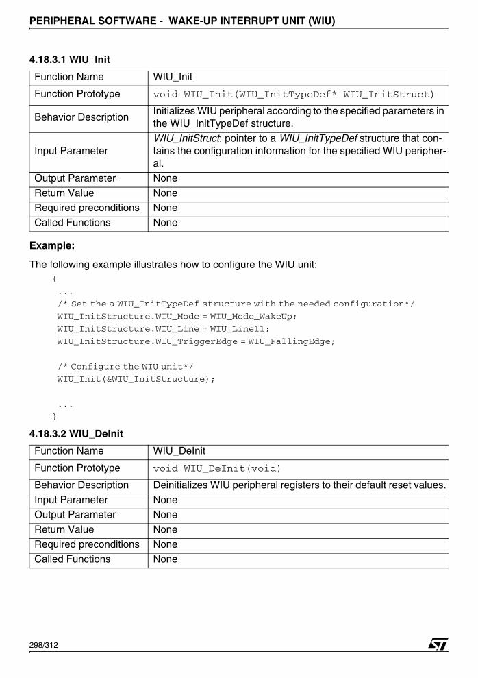
PERIPHERAL SOFTWARE - WAKE-UP INTERRUPT UNIT (WIU)
4.18.3.1 WIU_Init
Example:
The following example illustrates how to configure the WIU unit:{
...
/* Set the a WIU_InitTypeDef structure with the needed configuration*/
WIU_InitStructure.WIU_Mode = WIU_Mode_WakeUp;
WIU_InitStructure.WIU_Line = WIU_Line11;
WIU_InitStructure.WIU_TriggerEdge = WIU_FallingEdge;
/* Configure the WIU unit*/
WIU_Init(&WIU_InitStructure);
...
}
4.18.3.2 WIU_DeInit
Function Name WIU_Init
Function Prototype void WIU_Init(WIU_InitTypeDef* WIU_InitStruct)
Behavior DescriptionInitializes WIU peripheral according to the specified parameters in the WIU_InitTypeDef structure.
Input ParameterWIU_InitStruct: pointer to a WIU_InitTypeDef structure that con-tains the configuration information for the specified WIU peripher-al.
Output Parameter None
Return Value NoneRequired preconditions None
Called Functions None
Function Name WIU_DeInit
Function Prototype void WIU_DeInit(void)
Behavior Description Deinitializes WIU peripheral registers to their default reset values.
Input Parameter None
Output Parameter None
Return Value None
Required preconditions None
Called Functions None
298/312

PERIPHERAL SOFTWARE - WAKE-UP INTERRUPT UNIT (WIU)
Example:
The following example illustrates how to initialize the WIU registers to their reset value:{
....
WIU_DeInit();
....
}
4.18.3.3 WIU_StructInit
Example:
The following example illustrates how to initialise WIU Init Structure fields:{
WIU_InitTypeDef WIU_InitStructure;
...
WIU_StructInit(&WIU_InitStructure);
...
}
Function Name WIU_StructInit
Function Prototypevoid WIU_StructInit(WIU_InitTypeDef* WIU_InitStruct)
Behavior DescriptionFill in a WIU_InitTypeDef structure with the reset value of each pa-rameter (which depend on the register reset value).
Input ParameterWIU_InitStruct: pointer to a WIU_InitTypeDef structure which will be initialized.
Output Parameter None
Return Value None
Required preconditions None
Called Functions None
299/312
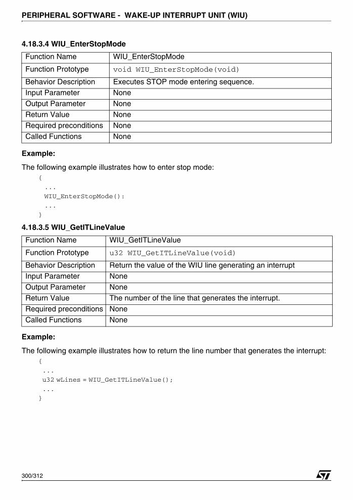
PERIPHERAL SOFTWARE - WAKE-UP INTERRUPT UNIT (WIU)
4.18.3.4 WIU_EnterStopMode
Example:
The following example illustrates how to enter stop mode:{
...
WIU_EnterStopMode():
...
}
4.18.3.5 WIU_GetITLineValue
Example:
The following example illustrates how to return the line number that generates the interrupt:{
...
u32 wLines = WIU_GetITLineValue();
...
}
Function Name WIU_EnterStopMode
Function Prototype void WIU_EnterStopMode(void)
Behavior Description Executes STOP mode entering sequence.Input Parameter None
Output Parameter None
Return Value None
Required preconditions None
Called Functions None
Function Name WIU_GetITLineValue
Function Prototype u32 WIU_GetITLineValue(void)
Behavior Description Return the value of the WIU line generating an interruptInput Parameter None
Output Parameter None
Return Value The number of the line that generates the interrupt.
Required preconditions None
Called Functions None
300/312
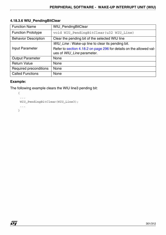
PERIPHERAL SOFTWARE - WAKE-UP INTERRUPT UNIT (WIU)
4.18.3.6 WIU_PendingBitClear
Example:
The following example clears the WIU line3 pending bit:{
...
WIU_PendingBitClear(WIU_Line3);
...
}
Function Name WIU_PendingBitClear
Function Prototype void WIU_PendingBitClear(u32 WIU_Line)
Behavior Description Clear the pending bit of the selected WIU line
Input ParameterWIU_Line : Wake-up line to clear its pending bit.
Refer to section 4.18.2 on page 296 for details on the allowed val-ues of WIU_Line parameter.
Output Parameter None
Return Value None
Required preconditions None
Called Functions None
301/312
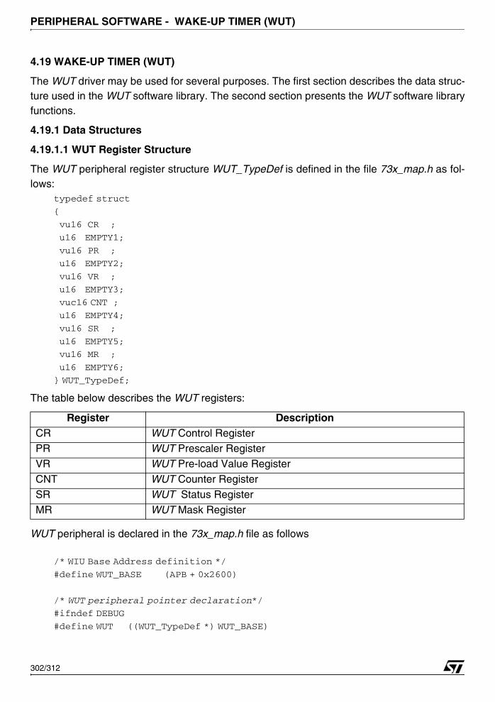
PERIPHERAL SOFTWARE - WAKE-UP TIMER (WUT)
4.19 WAKE-UP TIMER (WUT)
The WUT driver may be used for several purposes. The first section describes the data struc-ture used in the WUT software library. The second section presents the WUT software libraryfunctions.
4.19.1 Data Structures
4.19.1.1 WUT Register Structure
The WUT peripheral register structure WUT_TypeDef is defined in the file 73x_map.h as fol-lows:
typedef struct
{
vu16 CR ;
u16 EMPTY1;
vu16 PR ;
u16 EMPTY2;
vu16 VR ;
u16 EMPTY3;
vuc16 CNT ;
u16 EMPTY4;
vu16 SR ;
u16 EMPTY5;
vu16 MR ;
u16 EMPTY6;
} WUT_TypeDef;
The table below describes the WUT registers:
WUT peripheral is declared in the 73x_map.h file as follows
/* WIU Base Address definition */
#define WUT_BASE (APB + 0x2600)
/* WUT peripheral pointer declaration*/
#ifndef DEBUG
#define WUT ((WUT_TypeDef *) WUT_BASE)
Register DescriptionCR WUT Control RegisterPR WUT Prescaler Register
VR WUT Pre-load Value Register
CNT WUT Counter Register
SR WUT Status Register
MR WUT Mask Register
302/312

PERIPHERAL SOFTWARE - WAKE-UP TIMER (WUT)
...
else
...
EXT WIU_TypeDef *WUT;
...
#endif
When debug mode is used, WUT pointer is initialized in 73x_lib.c file: #ifdef _WUT
WUT = (WUT_TypeDef *)WUT_BASE;
#endif /* _WUT */
In debug mode, _WUT must be defined, in 73x_conf.h file, to include the WUT library #define _WUT
Some CFG registers are used in the main application to enable the Clock of the peripheral, inthe file 73x_conf.h, to make the CFG accessible, user must define:
#define _CFG
4.19.1.2 WUT_InitTypeDef Structure
The WUT_InitTypeDef structure defines the control setting for the Wake-Up Timer peripheral.typedef struct
{ u16 WUT_Mode;
u16 WUT_CLK_Source;
u16 WUT_Prescaler;
u16 WUT_Preload;
}WUT_InitTypeDef;
Members■ WUT_Mode
Specifies the WUT peripheral mode.
This member can be one of the following values
■ WUT_CLK_Source
Specifies the clock source of the WUT peripheral.
WUT Modes MeaningWUT_Mode_WakeUp WUT in a WakeUp mode
WUT_Mode_Timer WUT in a Timer mode
303/312
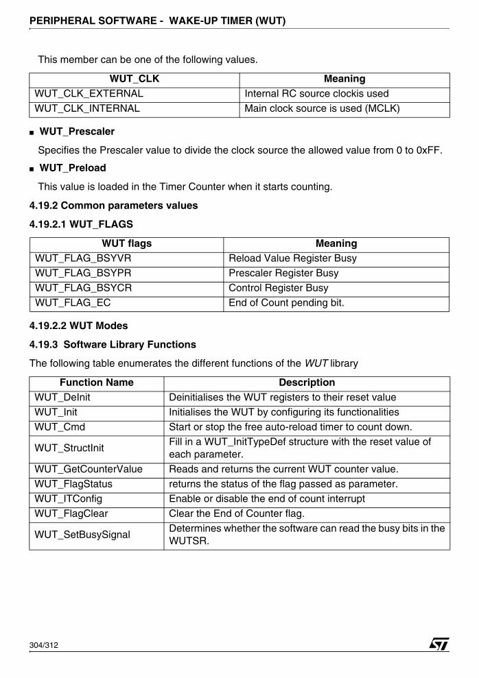
PERIPHERAL SOFTWARE - WAKE-UP TIMER (WUT)
This member can be one of the following values.
■ WUT_Prescaler
Specifies the Prescaler value to divide the clock source the allowed value from 0 to 0xFF.
■ WUT_Preload
This value is loaded in the Timer Counter when it starts counting.
4.19.2 Common parameters values
4.19.2.1 WUT_FLAGS
4.19.2.2 WUT Modes
4.19.3 Software Library Functions
The following table enumerates the different functions of the WUT library
WUT_CLK MeaningWUT_CLK_EXTERNAL Internal RC source clockis used
WUT_CLK_INTERNAL Main clock source is used (MCLK)
WUT flags MeaningWUT_FLAG_BSYVR Reload Value Register Busy
WUT_FLAG_BSYPR Prescaler Register Busy
WUT_FLAG_BSYCR Control Register Busy
WUT_FLAG_EC End of Count pending bit.
Function Name DescriptionWUT_DeInit Deinitialises the WUT registers to their reset value
WUT_Init Initialises the WUT by configuring its functionalities
WUT_Cmd Start or stop the free auto-reload timer to count down.
WUT_StructInitFill in a WUT_InitTypeDef structure with the reset value of each parameter.
WUT_GetCounterValue Reads and returns the current WUT counter value.
WUT_FlagStatus returns the status of the flag passed as parameter.WUT_ITConfig Enable or disable the end of count interrupt
WUT_FlagClear Clear the End of Counter flag.
WUT_SetBusySignalDetermines whether the software can read the busy bits in the WUTSR.
304/312
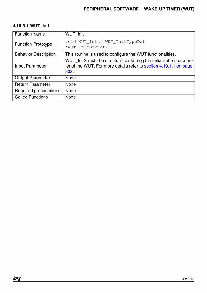
PERIPHERAL SOFTWARE - WAKE-UP TIMER (WUT)
4.19.3.1 WUT_Init
Function Name WUT_Init
Function Prototypevoid WUT_Init (WUT_InitTypeDef *WUT_InitStruct);
Behavior Description This routine is used to configure the WUT functionalities.
Input ParameterWUT_InitStruct: the structure containing the initialisation parame-ter of the WUT. For more details refer to section 4.19.1.1 on page 302.
Output Parameter None
Return Parameter None
Required preconditions None
Called Functions None
305/312
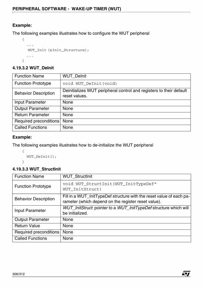
PERIPHERAL SOFTWARE - WAKE-UP TIMER (WUT)
Example:
The following examples illustrates how to configure the WUT peripheral{
...
WUT_Init (&Init_Structure);
...
}
4.19.3.2 WUT_DeInit
Example:
The following examples illustrates how to de-initialize the WUT peripheral{
WUT_DeInit();
}
4.19.3.3 WUT_StructInit
Function Name WUT_DeInit
Function Prototype void WUT_DeInit(void)
Behavior DescriptionDeinitializes WUT peripheral control and registers to their default reset values.
Input Parameter None
Output Parameter None
Return Parameter None
Required preconditions None
Called Functions None
Function Name WUT_StructInit
Function Prototypevoid WUT_StructInit(WUT_InitTypeDef* WUT_InitStruct)
Behavior DescriptionFill in a WUT_InitTypeDef structure with the reset value of each pa-rameter (which depend on the register reset value).
Input ParameterWUT_InitStruct: pointer to a WUT_InitTypeDef structure which will be initialized.
Output Parameter NoneReturn Value None
Required preconditions None
Called Functions None
306/312
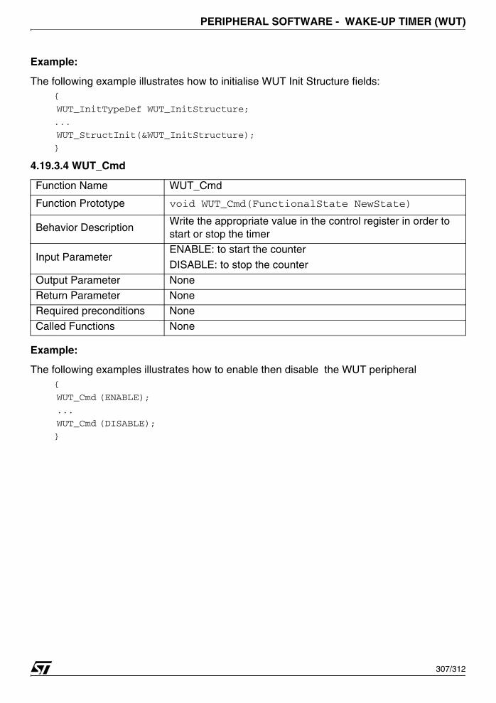
PERIPHERAL SOFTWARE - WAKE-UP TIMER (WUT)
Example:
The following example illustrates how to initialise WUT Init Structure fields:{
WUT_InitTypeDef WUT_InitStructure;
...
WUT_StructInit(&WUT_InitStructure);
}
4.19.3.4 WUT_Cmd
Example:
The following examples illustrates how to enable then disable the WUT peripheral{
WUT_Cmd (ENABLE);
...
WUT_Cmd (DISABLE);
}
Function Name WUT_Cmd
Function Prototype void WUT_Cmd(FunctionalState NewState)
Behavior Description Write the appropriate value in the control register in order to start or stop the timer
Input ParameterENABLE: to start the counter
DISABLE: to stop the counter
Output Parameter None
Return Parameter None
Required preconditions None
Called Functions None
307/312

PERIPHERAL SOFTWARE - WAKE-UP TIMER (WUT)
4.19.3.5 WUT_FlagStatus
Example:
The following examples illustrates how to check the FLAG_BSYVR of the WUT peripheral:if (WUT_FlagStatus(WUT_FLAG_BSYVR))
{
...
}
4.19.3.6 WUT_Flagclear
Example:
The following example illustrates how to clear the End Of Count Flag of the WUT :{
WUT_FlagClear();
}
Function Name WUT_FlagStatus
Function Prototype flagstatus WUT_FlagStatus (u16 WUT_Flag)
Behavior Description This routine returns the status of the specified flag.
Input Parameter WUT_Flag: specifies the flag to test the status.Refer to section 4.19.2.1 on page 304 for more details on the al-lowed values of this parameter.
Output Parameter None
Return ParameterThe status of the specified flag.SET: the flag is set.RESET: the flag is reset.
Required preconditions None
Called Functions None
Function Name WUT_ECFlagClear
Function Prototype void WUT_FlagClear (void)
Behavior Description Clear the The End of Count flag
Input Parameter None
Output Parameter None
Return Parameter NoneRequired preconditions None
Called Functions None
308/312

PERIPHERAL SOFTWARE - WAKE-UP TIMER (WUT)
4.19.3.7 WUT_GetCounterValue
Example:
The following example illustrates how to get tthe WUT counter value:{
u16 Myvalue = WUT_GetCounterValue();
}
4.19.3.8 WUT_ITConfig
Example:
The following example illustrates how to enable the end of count interrupt of the WUT:{
...
WUT_ITConfig (Enable);
...
}
Function Name WUT_GetCountervalue
Function Prototype u16 WUT_GetCounterValue (void)
Behavior Description This routine is used to get the counter value.
Input Parameter None
Output Parameter None
Return Parameter NoneRequired preconditions None
Called Functions None
Function Name WUT_ITConfig
Function Prototype void WUT_ITConfig(FunctionalState NewState)
Behavior Description Enable or disable the end of count interrupt
Input Parameter1 NewState: new state of the WUT peripheral. This parameter can be ENABLE or DISABLE.
Output Parameter None
Return Parameter None
Required preconditions None
Called Functions None
309/312

PERIPHERAL SOFTWARE - WAKE-UP TIMER (WUT)
4.19.3.9 WUT_SetBusySignal
Example:
The following example illustrates how to read the busy bits in the WUT peripheral:{
WUT_SetBusySignal (ENABLE);
}
Function Name WUT_SetBusySignal
Function Prototypevoid WUT_SetBusySignal (fonctionalstate NewState)
Behavior DescriptionThis routine is used to determines whether the software can read the busy bits in the WUTSR.
Input Parameter
NewState:
ENABLE: Busy bit are not masked.
DISABLE: Busy bit are masked
Output Parameter None
Return Parameter NoneRequired preconditions None
Called Functions None
310/312

REVISION HISTORY - WAKE-UP TIMER (WUT)
5 REVISION HISTORY
Date Revision Main changes27-Sep-2005 1 First Revision
311/312
REVISION HISTORY - WAKE-UP TIMER (WUT)
THE SOFTWARE INCLUDED IN THIS MANUAL IS FOR GUIDANCE ONLY. STMICROELECTRONICS SHALL NOT BE HELD LIABLE FOR ANY DIRECT, INDIRECT OR CONSEQUENTIAL DAMAGES WITH RESPECT TO ANY CLAIMS ARISING FROM USE OF THE SOFTWARE.
Information furnished is believed to be accurate and reliable. However, STMicroelectronics assumes no responsibility for the consequencesof use of such information nor for any infringement of patents or other rights of third parties which may result from its use. No license is grantedby implication or otherwise under any patent or patent rights of STMicroelectronics. Specifications mentioned in this publication are subjectto change without notice. This publication supersedes and replaces all information previously supplied. STMicroelectronics products are notauthorized for use as critical components in life support devices or systems without express written approval of STMicroelectronics.
The ST logo is a registered trademark of STMicroelectronics.
All other names are the property of their respective owners
© 2005 STMicroelectronics - All rights reserved
STMicroelectronics group of companies
Australia – Belgium - Brazil - Canada - China – Czech Republic - Finland - France - Germany - Hong Kong - India - Israel - Italy - Japan - Malaysia - Malta - Morocco - Singapore - Spain - Sweden - Switzerland - United Kingdom - United States of America
www.st.com
312/312


