SmartLine Technical Information STR700 SmartLine Remote Diaphragm Seals Specification 34-ST-03-104 Introduction Part of the SmartLine® family of products, the STR700 is suitable for monitoring, control and data acquisition. STR700 products feature piezoresistive sensor technology combining pressure sensing with on chip temperature compensation capabilities providing high accuracy, stability and performance over a wide range of application pressures and temperatures. The SmartLine family is also fully tested and compliant with Experion ® PKS providing the highest level of compatibility assurance and integration capabilities. SmartLine easily meets the most demanding application needs for pressure measurement applications Best in Class Transmitter Features: • Accuracies up to 0.075% standard • Automatic static pressure & temperature compensation • Rangeability up to 100:1 • Local display capabilities • External zero, span, & configuration capability • Polarity insensitive electrical connections • Comprehensive on-board diagnostic capabilities • Integral Dual Seal design for highest safety based on ANSI/NFPA 70-202 and ANSI/ISA 12.27.0 • World class overpressure protection • Full compliance to SIL 2/3 requirements. • Modular design characteristics • Available with 15 year warranty Remote Seal/Transmitter Span & Range Limits: Model psid (bar) psid (bar) psid (bar) psid (bar) STR73D 100 (7.0) -100 (-7.0) 100 (7.0) 1 (0.07) Model psig (bar) psig (bar) psig (bar) psig (bar) STR74G 500 (35.0) -500 (-35.0) 500 (35.0) 5 (035) Figure 1 – STR700 Remote Diaphragm Seal Unit Typical Diaphragm Seal applications • High Process Temperatures • Viscous or Suspended Solids • Highly Corrosive Process Materials • Sanitary Applications • Applications with Hydrogen Permeation Possibilities • Level Applications with Maintenance Intensive Wet Legs • Applications requiring remote Transmitter Mounting • Tank Applications with Density or Interface Measurements Communications/Output Options: • Honeywell Digitally Enhanced (DE) • HART ® (version 7.0) • FOUNDATION™ Fieldbus All transmitters are available with the above listed communications protocols.
All transmitters are available with the above listed
communications protocols.
2 STR700 Smart Pressure Transmitter
Description
The SmartLine family pressure transmitters are designed around a high performance piezo-resistive sensor. This one sensor actually integrates multiple sensors linking process pressure measurement with on-board static pressure (DP Models) and temperature compensation measurements. This level of performance allows the ST 700 to replace most competitive transmitters available today.
Indication/Display Option
The ST 700 modular design accommodates a basic
alphanumeric LCD display.
Basic Alphanumeric LCD Display Features
o Modular (may be added or removed in the field)
o 0, 90,180, & 270 degree position adjustments
o Pa, KPa, MPa, KGcm2, Torr, ATM, i4H2O, mH2O,
bar, mbar, inH2O, inHG, FTH2O, mmH2O, mm HG,
& psi measurement units
o 2 Lines 16 Characters (4.13H x 1.83W mm)
o Square root output indication (√)
Diagnostics SmartLine transmitters all offer digitally accessible diagnostics which aid in providing advanced warning of possible failure events minimizing unplanned shutdowns, providing lower overall operational costs
Configuration Tools
Integral Three Button Configuration Option Suitable for all electrical and environmental requirements, SmartLine offers the ability to configure the transmitter and display via three externally accessible buttons when a display option is selected. Zero/span capabilities are also optionally available via these buttons with or without selection of the display option.
Hand Held Configuration SmartLine transmitters feature two-way communication and configuration capability between the operator and the transmitter. This is accomplished via Honeywell’s field-rated Multiple Communication Configurator (MCT202). The MCT202 is capable of field configuring DE and HART Devices and can also be ordered for use in intrinsically safe environments. All Honeywell transmitters are designed and tested for compliance with the offered communication protocols and are designed to operate with any properly validated hand held configuration device.
Personal Computer Configuration Honeywell’s SCT 3000 Configuration Toolkit provides an easy way to configure Digitally Enhanced (DE) instruments using a personal computer as the configuration interface. Field Device Manager (FDM) Software and FDM Express are also available for managing HART & Fieldbus device configurations.
System Integration
o SmartLine communications protocols all meet the
most current published standards for
HART/DE/Fieldbus.
o Integration with Honeywell’s Experion PKS offers the
following unique advantages.
o Tamper reporting
o FDM Plant Area Views with Health summaries
o All ST 700 units are Experion tested to provide
the highest level of compatibility assurance
Modular Design To help contain maintenance & inventory costs, all ST 700 transmitters are modular in design supporting the user’s ability to replace meter bodies, add indicators or change electronic modules without affecting overall performance or approval body certifications. Each meter body is uniquely characterized to provide in-tolerance performance over a wide range of application variations in temperature and pressure and due to the Honeywell advanced interface, electronic modules may be swapped with any electronics module without losing in-tolerance performance characteristics.
Modular Features
o Meter body replacement
o Exchange/replace electronics/comms modules*
o Add or remove integral indicator*
o Add or remove lightning protection (terminal
connection)*
* Field replaceable in all electrical environments (including IS) except flameproof without violating agency approvals.
With no performance effects, Honeywell’s unique modularity results in lower inventory needs and lower overall operating costs.
STR700 Smart Pressure Transmitter 3
Reference Accuracy 2 (conformance to +/-3 Sigma)
Total Performance (% of Span):
Total Performance = +/- √( Accuracy)2 + (Temp Effect)2
Total Performance Examples: (5:1 Turndown, up to 50 oF shift)
STR73D @ 20 psid: 1.03% of span
Typical Calibration Frequency: Calibration verification is recommended every four (4) years
Notes:
1.Terninal Based Accuracy – Includes combined effects of linearity, hysteresis, and repeatability. Analog output adds 0.005% of span.
2. For zero based spans and reference conditions of 25oC (77oF), 0 psig static pressure, 10 to 55% R.H, and 316Stainless Steel barrier diaphragms
3. Specification applies to transmitter with 2 seals. Apply a factor of 1.5 for temperature effect of capillary lengths greater then 10 feet.
Model URL LRL Min Span
Maximum Turndown
Ratio
Reference Accuracy1
(% Span) STR73D 100 psid/7.0 bar -100 psi/-7.0bar 9 psi/.07bar 100:1 0.075 STR74G 500 psi/35 bar -14.7 psi/-1.0 bar 5 psi/.035 bar 100:1 0.075
Performance Specifications1
Accuracy at Specified Span, Temperature and Static Pressure: (conformance to +/-3 Sigma)
Zero and span may be set anywhere within the listed (URL/LRL) range limits
Note: A minimum of 250 ohms of loop resistance is required to support communications. Loop resistance = barrier resistance + wire resistance + receiver resistance.
RLmax = 45.6 x (Power Supply Voltage – 10.8)
Operating Conditions – All Models
Parameter Reference
Condition (at zero static)
Rated Condition Operative Limits Transportation and Storage
°C °F °C °F °C °F °C °F
Ambient Temperature1 25±1 77±2 - - - - -55 to 90 -67 to 194
Humidity %RH 10 to 55 0 to 100 0 to 100 0 to 100
Vacuum Region, Minimum Pressure mmHg absolute
Atmospheric (See Figure 4 for vacuum limitation)
Supply Voltage, Current, and Load Resistance
10.8 to 42.4 Vdc at terminals (IS versions limited to 30 Vdc) 0 to 1,440 ohms (as shown in Figure 2)
Maximum Allowable Working Pressure (MAWP)4
(ST 700 products are rated to Maximum Allowable Working Pressure. MAWP depends on Approval Agency and transmitter materials of construction.)
MAWP is minimum of Body Rating or Seal Rating (See Model Selection Guide for Seal MAWP)
Body MAWP
STR73D 750 psig (51.7 bar) Bolted Process Heads
STR74G 500 psig (35 bar)
1 Ambient Temperature Limit is a function of Process Interface Temperature. (See Figures 3 & 4)
LCD Display operating temperature -20°C to +70°C . Storage temperature -30°C to 80°C 4 Consult factory for MAWP of ST 700 transmitters with CRN approval.
Figure 2 - Supply voltage and loop resistance Figure 3 - Ambient temperature Limits
200180
160
140120100
80
60
4020
0
185165
Maximum Ambient Temperature (°F)
140
350200 450
Process Interface Temperature (°F)
200180
160
140120100
80
60
4020
0
185165
Maximum Ambient Temperature (°F)
140
350200 450
Process Interface Temperature (°F)
STR700 Smart Pressure Transmitter 5
Figure 4 - STR700 Remote Seals operable limits for pressure vs. temperature
6 STR700 Smart Pressure Transmitter
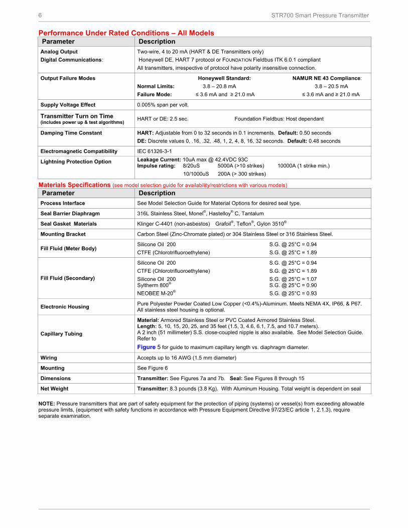
Performance Under Rated Conditions – All Models Parameter Description
Analog Output
Digital Communications:
Two-wire, 4 to 20 mA (HART & DE Transmitters only)
Honeywell DE, HART 7 protocol or FOUNDATION Fieldbus ITK 6.0.1 compliant
All transmitters, irrespective of protocol have polarity insensitive connection.
Output Failure Modes Honeywell Standard: NAMUR NE 43 Compliance:
Normal Limits: 3.8 – 20.8 mA 3.8 – 20.5 mA
Failure Mode: ≤ 3.6 mA and ≥ 21.0 mA ≤ 3.6 mA and ≥ 21.0 mA
Supply Voltage Effect 0.005% span per volt.
Transmitter Turn on Time (includes power up & test algorithms) HART or DE: 2.5 sec. Foundation Fieldbus: Host dependant
Damping Time Constant HART: Adjustable from 0 to 32 seconds in 0.1 increments. Default: 0.50 seconds
Electronic Housing Pure Polyester Powder Coated Low Copper (<0.4%)-Aluminum. Meets NEMA 4X, IP66, & P67. All stainless steel housing is optional.
Capillary Tubing
Material: Armored Stainless Steel or PVC Coated Armored Stainless Steel. Length: 5, 10, 15, 20, 25, and 35 feet (1.5, 3, 4.6, 6.1, 7.5, and 10.7 meters). A 2 inch (51 millimeter) S.S. close-coupled nipple is also available. See Model Selection Guide. Refer to
Figure 5 for guide to maximum capillary length vs. diaphragm diameter.
Wiring Accepts up to 16 AWG (1.5 mm diameter)
Mounting See Figure 6
Dimensions Transmitter: See Figures 7a and 7b. Seal: See Figures 8 through 15
Net Weight Transmitter: 8.3 pounds (3.8 Kg). With Aluminum Housing. Total weight is dependent on seal
NOTE: Pressure transmitters that are part of safety equipment for the protection of piping (systems) or vessel(s) from exceeding allowable pressure limits, (equipment with safety functions in accordance with Pressure Equipment Directive 97/23/EC article 1, 2.1.3), require separate examination.
STR700 Smart Pressure Transmitter 7
Minimum recommended span for STR73D Transmitter with two Remote Seals
Diaphragm
Size
Capillary Capillary Length
Maximum 5” 10” 15” 20” 30” 35”
2.4 200 iwc 5’
2.9 100 iwc 125 iwc 150 iwc 175 iwc 20’
3.5 16 iwc 20 iwc 24 iwc 28 iwc 36 iwc 40 iwc 35’
4.1 12 iwc 15 iwc 18 iwc 21 iwc 27 iwc 30 iwc 35’
Minimum recommended span for STR73D Transmitter with one Remote Seal
Figure 5– Typical Maximum capillary length and diaphragm size chart
Figure 6 - STR700 transmitter with remote diaphragm seals shown mounted on a tank
8 STR700 Smart Pressure Transmitter
Reference Dimensions Horizontal Mounting
STR700 Smart Pressure Transmitter 9
Reference Dimensions Horizontal Mounting (cont’d)
Figure 7 — Approximate horizontal mounting dimensions for Remote Seal Transmitter
Reference Dimensions Vertical Mounting
10 STR700 Smart Pressure Transmitter
Reference Dimensions Vertical Mounting (cont’d)
Figure 8 — Approximate vertical mounting dimensions for Remote Seal Transmitter
STR700 Smart Pressure Transmitter 11
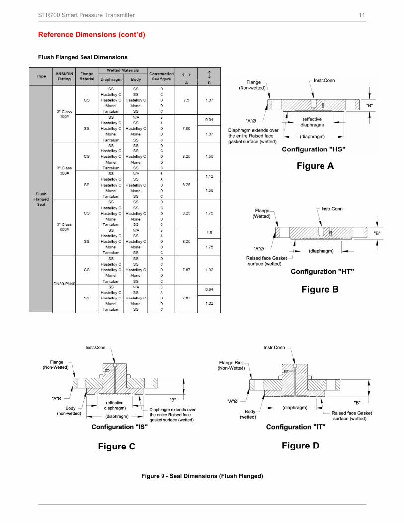
Reference Dimensions (cont’d)
Flush Flanged Seal Dimensions
Figure 9 - Seal Dimensions (Flush Flanged)
Figure A
Figure B
Figure C Figure D
12 STR700 Smart Pressure Transmitter
Reference Dimensions (cont’d)
Flush Flanged Seal with Lower
Figure 10- Seal Dimension (Flush Flanged)
Flush Flanged Seal with Lower Flush Flanged Seal with Lower
Note: 0.90 dimension is 0.70 for 4.1” Dia Diaphragm
STR700 Smart Pressure Transmitter 13
Reference Dimensions (cont’d)
Flanged Seal with Extended Diaphragm
Figure 11 — Seal Dimensions (Extended Diaphragms) Pancake Seal
Figure 12 — Seal Dimensions (Pancake) Chemical Tee “Taylor Wedge” Seal
Figure 13 — Seal Dimensions (Chemical TEE “Taylor Wedge” Seals
14 STR700 Smart Pressure Transmitter
Seal with Threaded Process Connection
Figure 14— Seal Dimensions (Threaded Process Connection Seals)
Sanitary Seal
Figure 15— Seal Dimensions (Sanitary Seals)
STR700 Smart Pressure Transmitter 15
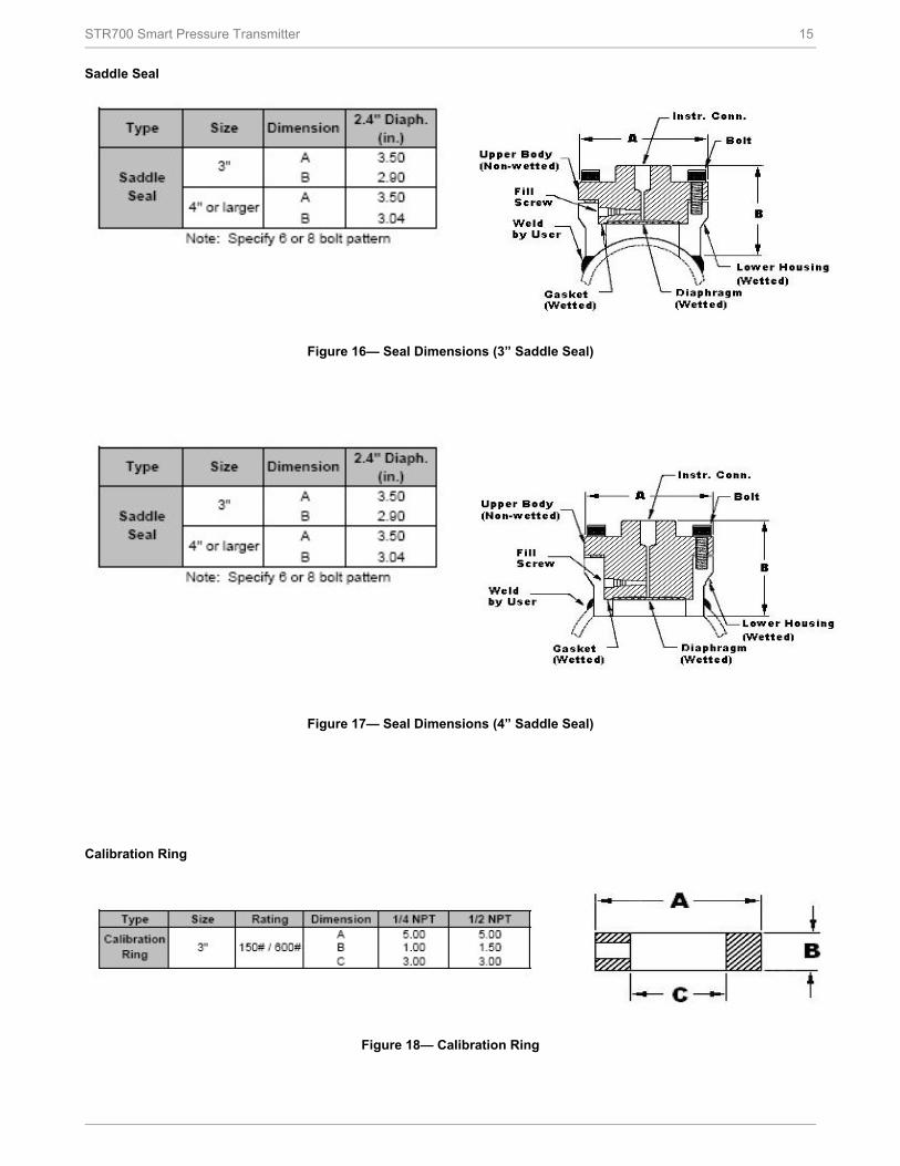
Saddle Seal
Figure 16— Seal Dimensions (3” Saddle Seal)
Figure 17— Seal Dimensions (4” Saddle Seal)
Calibration Ring
Figure 18— Calibration Ring
16 STR700 Smart Pressure Transmitter
Communications Protocols & Diagnostics
HART Protocol
Version:
HART 7
Power Supply
Voltage: 10.8 to 42.4Vdc at terminals
Load: Maximum 1440 ohms. See Figure 2.
Minimum Load: 0 ohms. (For handheld communications a
minimum load of 250 ohms is required)
Foundation Fieldbus (FF)
Power Supply Requirements
Voltage: 9.0 to 32.0Vdc at terminals
Steady State Current: 17.6mAdc
Software Download Current: 27.4mAdc
Available Function Blocks
Block Type Qty Execution Time
Resource 1 n/a
Transducer 1 n/a
Diagnostic 1 n/a
Analog Input 1* 30 ms
PID w/Autotune 1 45 ms
Integrator 1 30 ms
Signal Char (SC) 1 30 ms
LCD Display 1 n/a
Flow Block 1 30 ms
Input Selector 1 30 ms
Arithmetic 1 30 ms
* AI block may have two (2) additional instantiations.
All available function blocks adhere to FOUNDATION
Fieldbus standards. PID blocks support ideal & robust PID
algorithms with full implementation of Auto-tuning.
Link Active Scheduler
Transmitters can perform as a backup Link Active
Scheduler and take over when the host is disconnected.
Acting as a LAS, the device ensures scheduled data
transfers typically used for the regular, cyclic transfer of
control loop data between devices on the Fieldbus.
Number of Devices/Segment
Entity IS model: 6 devices/segment
Schedule Entries
18 maximum schedule entries
Number of VCR’s: 24 max
Compliance Testing: Tested according to ITK 6.0.1
Software Download
Utilizes Class-3 of the Common Software Download
procedure as per FF-883 which allows the field devices of
any manufacturer to receive software upgrades from any
host.
Honeywell Digitally Enhanced (DE)
DE is a Honeywell proprietary protocol which provides
digital communications between Honeywell DE enabled
field devices and Hosts.
Power Supply
Voltage: 10.8 to 42.4Vdc at terminals
Load: Maximum 1440 ohms See Figure 2.
Standard Diagnostics
ST 700 top level diagnostics are reported as either critical
or non-critical and readable via the DD/DTM tools or
integral display as shown below.
Refer to ST 700 manuals for additional level diagnostic
information
Other Certification Options
Materials
o NACE MRO175, MRO103, ISO15156
STR700 Smart Pressure Transmitter 17
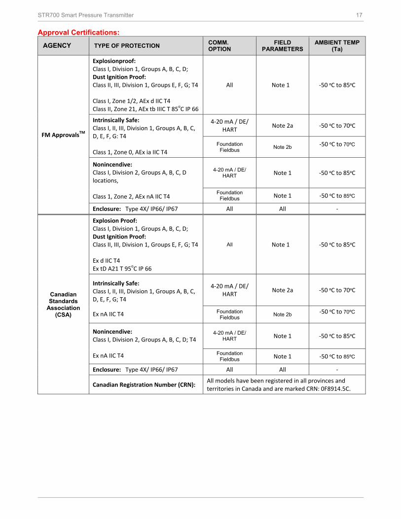
Approval Certifications:
AGENCY TYPE OF PROTECTION COMM. OPTION
FIELD PARAMETERS
AMBIENT TEMP (Ta)
FM ApprovalsTM
Explosionproof: Class I, Division 1, Groups A, B, C, D; Dust Ignition Proof: Class II, III, Division 1, Groups E, F, G; T4 Class I, Zone 1/2, AEx d IIC T4 Class II, Zone 21, AEx tb IIIC T 85oC IP 66
All Note 1 -50 ºC to 85ºC
Intrinsically Safe: Class I, II, III, Division 1, Groups A, B, C, D, E, F, G: T4 Class 1, Zone 0, AEx ia IIC T4
4-20 mA / DE/ HART
Note 2a -50 ºC to 70ºC
Foundation Fieldbus
Note 2b -50 ºC to 70ºC
Nonincendive: Class I, Division 2, Groups A, B, C, D locations, Class 1, Zone 2, AEx nA IIC T4
4-20 mA / DE/ HART Note 1 -50 ºC to 85ºC
Foundation Fieldbus Note 1 -50 ºC to 85ºC
Enclosure: Type 4X/ IP66/ IP67 All All -
Canadian Standards
Association (CSA)
Explosion Proof: Class I, Division 1, Groups A, B, C, D; Dust Ignition Proof: Class II, III, Division 1, Groups E, F, G; T4 Ex d IIC T4 Ex tD A21 T 95oC IP 66
All Note 1 -50 ºC to 85ºC
Intrinsically Safe: Class I, II, III, Division 1, Groups A, B, C, D, E, F, G; T4 Ex nA IIC T4
4-20 mA / DE/ HART
Note 2a -50 ºC to 70ºC
Foundation Fieldbus
Note 2b -50 ºC to 70ºC
Nonincendive: Class I, Division 2, Groups A, B, C, D; T4 Ex nA IIC T4
4-20 mA / DE/ HART Note 1 -50 ºC to 85ºC
Foundation Fieldbus Note 1 -50 ºC to 85ºC
Enclosure: Type 4X/ IP66/ IP67 All All -
Canadian Registration Number (CRN): All models have been registered in all provinces and territories in Canada and are marked CRN: 0F8914.5C.
18 STR700 Smart Pressure Transmitter
Approval Certifications: (Continued)
ATEX
Flameproof: II 1/2 G Ex d IIC T4 II 2 D Ex tb IIIC T 85oC IP 66
All Note 1 -50 ºC to 85ºC
Intrinsically Safe: II 1 G Ex ia IIC T4
4-20 mA / DE/ HART
Note 2a -50 ºC to 70ºC
Foundation Fieldbus
Note 2b -50 ºC to 70ºC
Nonincendive: II 3 G Ex nA IIC T4
4-20 mA / DE/ HART Note 1 -50 ºC to 85ºC
Foundation Fieldbus Note 1 -50 ºC to 85ºC
Enclosure: IP66/ IP67 All All All
IECEx (World)
Flameproof : Ga/Gb Ex d IIC T4 Ex tb IIIC T 85oC IP 66
All Note 1 -50 ºC to 85ºC
Intrinsically Safe: Ex ia IIC T4
4-20 mA / DE/ HART
Note 2a -50 ºC to 70ºC
Foundation Fieldbus
Note 2b -50 ºC to 70ºC
Nonincendive: Ex nA IIC T4
4-20 mA / DE/ HART Note 1 -50 ºC to 85ºC
Foundation Fieldbus Note 1 -50 ºC to 85ºC
Enclosure: IP66/ IP67 All All All
SAEx (South Africa)
Flameproof : Ga/Gb Ex d IIC T4 Ex tb IIIC T 85oC IP 66
All Note 1 -50 ºC to 85ºC
Intrinsically Safe: Ex ia IIC T4
4-20 mA / DE/ HART
Note 2a -50 ºC to 70ºC
Foundation Fieldbus
Note 2b -50 ºC to 70ºC
Nonincendive: Ex nA IIC T4
4-20 mA / DE/ HART Note 1 -50 ºC to 85ºC
Foundation Fieldbus Note 1 -50 ºC to 85ºC
Enclosure: IP66/ IP67 All All All
INMETRO
(Brazil)
Flameproof: Br- Ga/Gb Ex d IIC T4 Br- Ex tb IIIC T 85oC IP 66
All Note 1 -50 ºC to 85ºC
Intrinsically Safe: Br- Ex ia IIC T4
4-20 mA / DE/ HART
Note 2a -50 ºC to 70ºC
Foundation Fieldbus
Note 2b -50 ºC to 70ºC
Nonincendive: Ex nA IIC T4
4-20 mA / DE/ HART Note 1 -50 ºC to 85ºC
Foundation Fieldbus Note 1 -50 ºC to 85ºC
Enclosure : IP 66/67 All All -
STR700 Smart Pressure Transmitter 19
NEPSI (China)
Flameproof: Br- Ga/Gb Ex d IIC T4 Br- Ex tb IIIC T 85oC IP 66
All Note 1 -50 ºC to 85ºC
Intrinsically Safe: Br- Ex ia IIC T4
4-20 mA / DE/ HART
Note 2a -50 ºC to 70ºC
Foundation Fieldbus
Note 2b -50 ºC to 70ºC
Nonincendive: Ex nA IIC T4
4-20 mA / DE/ HART Note 1 -50 ºC to 85ºC
Foundation Fieldbus Note 1 -50 ºC to 85ºC
Enclosure : IP 66/67 All All -
Notes: 1. Operating Parameters:
Voltage = 11 to 42 V DC = 10 to 30 V (FF)
Current = 4-20 mA Normal (3.8 – 23 mA Faults) = 30 mA (FF)
Vmax= Ui = 30V After 27th September 2013 Vmax= Ui = 30V
Imax= Ii= 105mA Imax= Ii= 225mA
Ci = 4.2nF Ci = 4.2nF
Li = 984 uH Li = 0 uH
Pi =0.9W Pi =0.9W
b. Foundation Fieldbus- Entity Values Vmax= Ui = 30V Imax= Ii= 225mA Ci = 0nF Li = 0 uH Pi =1W
Marine Certificates
This certificate defines the certifications covered for the ST 700 Pressure Transmitter family of products. It represents the compilation of the five certificates Honeywell currently has covering the certification of these products into marine applications.
American Bureau of Shipping (ABS) - 2009 Steel Vessel Rules 1-1-4/3.7, 4-6-2/5.15, 4-8-3/13 &
SIL 2/3 Certification IEC 61508 SIL 2 for non-redundant use and SIL 3 for redundant use according to EXIDA and TÜV Nord Sys Tec GmbH & Co. KG under the following standards: IEC61508-1: 2010; IEC 61508-2: 2010; IEC61508-3: 2010.
20 STR700 Smart Pressure Transmitter
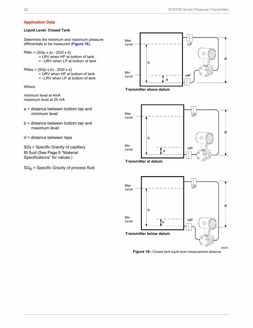
Application Data
Liquid Level: Closed Tank Determine the minimum and maximum pressure differentials to be measured (Figure 16). PMin = (SGp x a) - (SGf x d) = LRV when HP at bottom of tank = –URV when LP at bottom of tank PMax = (SGp x b) - (SGf x d) = URV when HP at bottom of tank = –LRV when LP at bottom of tank Where: minimum level at 4mA maximum level at 20 mA a = distance between bottom tap and
minimum level b = distance between bottom tap and
maximum level d = distance between taps SGf = Specific Gravity of capillary fill fluid (See Page 6 “Material Specifications” for values.) SGp = Specific Gravity of process fluid
b
a
LP
HP
24253
MaxLevel
MinLevel
Transmitter above datum
LP
HP
b
a
MaxLevel
MinLevel
Transmitter at datum
LP
HP
b
a
MaxLevel
MinLevel
Transmitter below datum
Figure 16—Closed tank liquid level measurement distance
STR700 Smart Pressure Transmitter 21
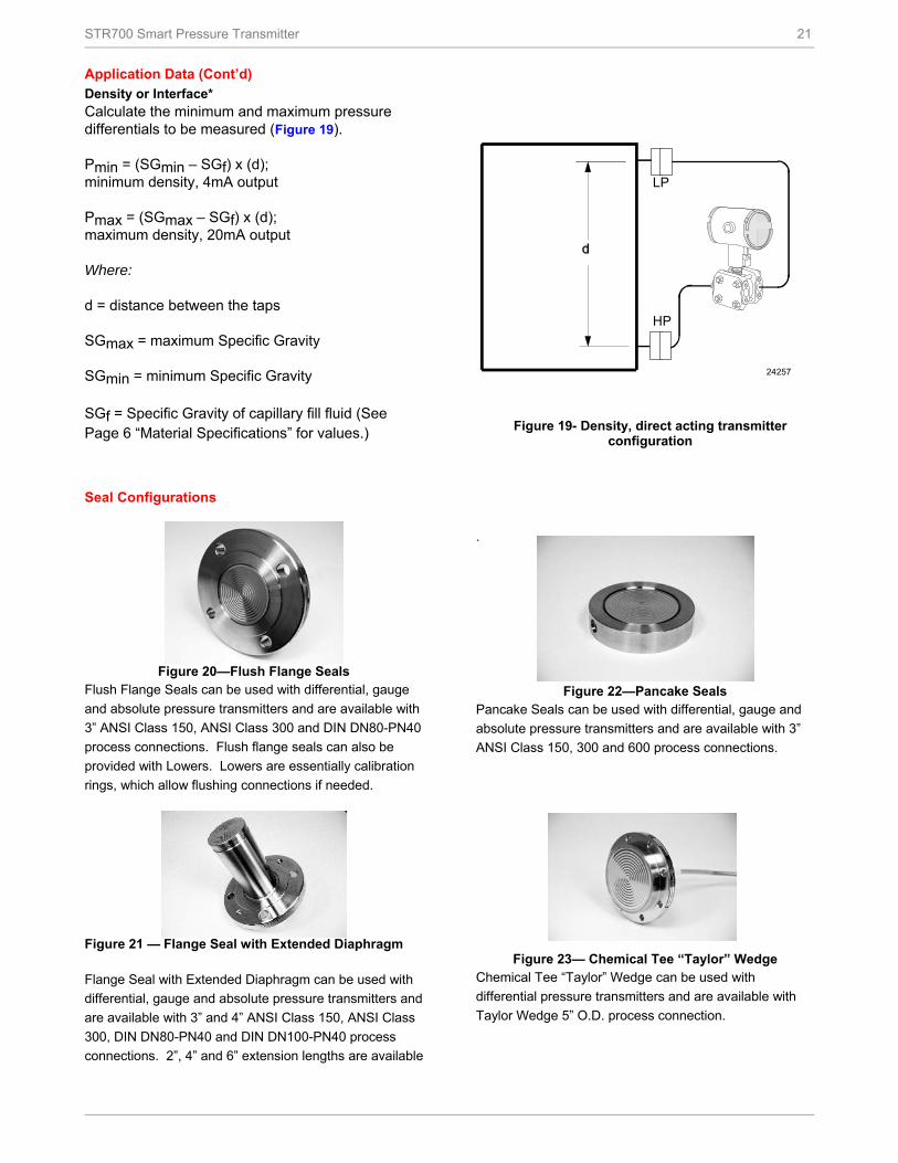
Application Data (Cont’d)
Density or Interface* Calculate the minimum and maximum pressure differentials to be measured (Figure 19). Pmin = (SGmin – SGf) x (d); minimum density, 4mA output Pmax = (SGmax – SGf) x (d); maximum density, 20mA output Where: d = distance between the taps SGmax = maximum Specific Gravity SGmin = minimum Specific Gravity
SGf = Specific Gravity of capillary fill fluid (See Page 6 “Material Specifications” for values.)
LP
HP
24257
Figure 19- Density, direct acting transmitter
configuration
Seal Configurations
Figure 20—Flush Flange Seals
Flush Flange Seals can be used with differential, gauge
and absolute pressure transmitters and are available with
3” ANSI Class 150, ANSI Class 300 and DIN DN80-PN40
process connections. Flush flange seals can also be
provided with Lowers. Lowers are essentially calibration
rings, which allow flushing connections if needed.
Figure 21 — Flange Seal with Extended Diaphragm
Flange Seal with Extended Diaphragm can be used with
differential, gauge and absolute pressure transmitters and
are available with 3” and 4” ANSI Class 150, ANSI Class
300, DIN DN80-PN40 and DIN DN100-PN40 process
connections. 2”, 4” and 6” extension lengths are available
.
Figure 22—Pancake Seals Pancake Seals can be used with differential, gauge and
absolute pressure transmitters and are available with 3”
ANSI Class 150, 300 and 600 process connections.
Figure 23— Chemical Tee “Taylor” Wedge Chemical Tee “Taylor” Wedge can be used with
differential pressure transmitters and are available with
Taylor Wedge 5” O.D. process connection.
22 STR700 Smart Pressure Transmitter
Seal Configurations (cont’d)
Figure 24— Seals with Threaded Process Connections
Seals with Threaded Process Connections can be used
with differential, gauge and absolute pressure
transmitters and are available with ½”, ¾” and 1” NPT
Female process connections.
Figure 25 — Sanitary Seals
Sanitary Seals can be used with differential, gauge and
absolute pressure transmitters and are available with 3”
and 4” Tri-Clover-Tri-Clamp process connections.
Figure 26— Saddle Seals
Saddle Seals can be used with differential, gauge and
absolute pressure transmitters and are available with 3”
and 4” (6 bolt or 8 bolt designs) process connections.
Figure 27 — Calibration Rings Calibration Rings are available with Flush Flange Seals
and Pancake Seals. Flushing ports (1/4” or ½”) are
Stainless Steel Armor and PVC Coated Stainless Steel
Armor Capillaries are available with Honeywell Remote
Seal Solutions.
Figure 29 — 2” Stainless Steel Nipples 2” Stainless Steel Nipples are available for Close-Coupled remote seal solutions
Figure 30 — Welded Meter Body for All-Welded Remote Seal Solution
Welded Meter Body for All-Welded Remote Seal Solution.
The welded ST 800 meter body is an important part of an
All-Welded Remote Seal Solution, which is commonly
used in Vacuum applications.
STR700 Smart Pressure Transmitter 23
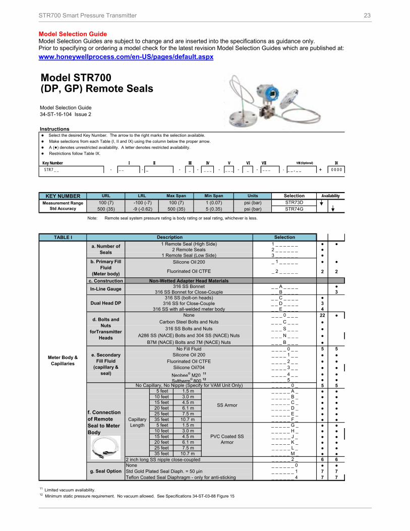
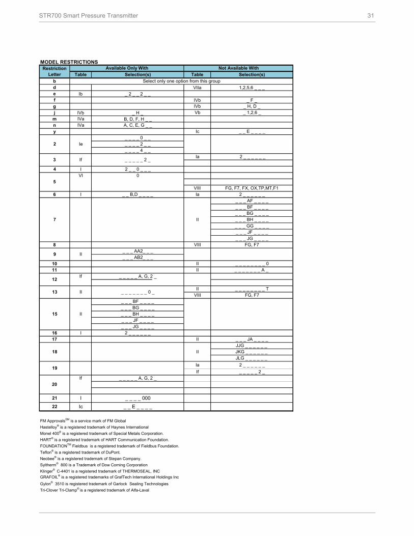
Model Selection Guide Model Selection Guides are subject to change and are inserted into the specifications as guidance only. Prior to specifying or ordering a model check for the latest revision Model Selection Guides which are published at:
www.honeywellprocess.com/en-US/pages/default.aspx
Model STR700(DP, GP) Remote Seals
Model Selection Guide34-ST-16-104 Issue 2
Instructions ● Select the desired Key Number. The arrow to the right marks the selection available.
● Make selections from each Table (I, II and IX) using the column below the proper arrow.
● A (●) denotes unrestricted availability. A letter denotes restricted availability.
● Restrictions follow Table IX.
Key Number I II III IV V VI VII VIII (Optional) IX
A286 SS (NACE) Bolts and 304 SS (NACE) Nuts _ _ _ N _ _ _
B7M (NACE) Bolts and 7M (NACE) Nuts
g. Seal OptionNone _ _ _ _ _ _ 0Std Gold Plated Seal Diaph. = 50 µin
_ _ _ _ _ B _15 feet 4.5 m _ _ _ _ _ C _20 feet 6.1 m _ _ _ _ _ D _
f. Connection of Remote Seal to Meter Body
No Capillary, No Nipple (Specify for VAM Unit Only) _ _ _ _ _ 0 _
Capillary Length
5 feet 1.5 m
SS Armor
_ _ _ _ _ A _10 feet 3.0 m
20 feet 6.1 m _ _ _ _ _ K _25 feet 7.5 m _ _ _ _ _ L _
5 feet 1.5 m
PVC Coated SS Armor
_ _ _ _ _ G _10 feet
_ _ _ _ _ J _
25 feet 7.5 m _ _ _ _ _ E _35 feet 10.7 m _ _ _ _ _ F _
Teflon Coated Seal Diaphragm - only for anti-sticking _ _ _ _ _ _ 4
35 feet 10.7 m _ _ _ _ _ M _2 inch long SS nipple close-coupled _ _ _ _ _ 2 _
3.0 m _ _ _ _ _ H _15 feet 4.5 m
_ _ _ _ _ _ 1
24 STD800 Smart Pressure Transmitter
In-Line Gauge All welded
STR74G
STR73D
Note: When selecting required seal, you must specifyonly the 9 selections within the required seal type.
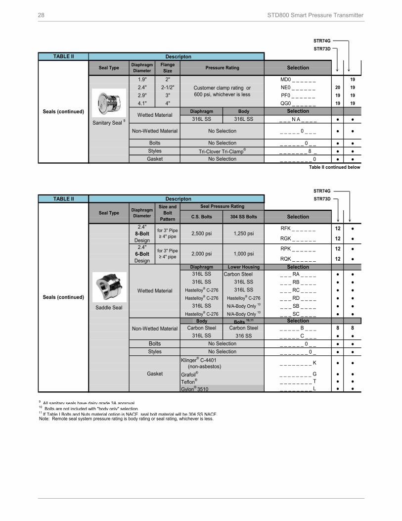
TABLE II
21 21
AFA _ _ _ _ _ _ ● ●AFC _ _ _ _ _ _ ● ●
AFM _ _ _ _ _ _ ● ●
_ _ _ AA _ _ _ _ ● ●_ _ _ AB _ _ _ _ ● ●_ _ _ AC _ _ _ _ ● ●
_ _ _ AE _ _ _ _ ● ●
_ _ _ AF _ _ _ _ 8 8
_ _ _ _ _ 1 _ _ _ ● ●
_ _ _ _ _ 2 _ _ _ ● ●
_ _ _ _ _ _ 1 _ _ ● ●
_ _ _ _ _ _ 2 _ _ 9 9
_ _ _ _ _ _ _ A _ ● ●
_ _ _ _ _ _ _ B _ 10 10
_ _ _ _ _ _ _ C _ 10 10
_ _ _ _ _ _ _ D _ 10 10
_ _ _ _ _ _ _ _ 0 ● ●
_ _ _ _ _ _ _ _ H 11 11
_ _ _ _ _ _ _ _ J 11 11
(Metal plug material _ _ _ _ _ _ _ _ M 11 11
will be the same as _ _ _ _ _ _ _ _ N 11 11
Cal. ring material if _ _ _ _ _ _ _ _ P 11 11
metal plug is chosen ) _ _ _ _ _ _ _ _ Q 11 11
_ _ _ _ _ _ _ _ R 11 11
_ _ _ _ _ _ _ _ S 11 11Table II continued next page
1 Standard facing 125-250 AARH RF (raised face) serrated surface finish.4 Plastic Plugs are TEMPORARY ONLY to protect threads and MUST be REMOVED before installation5 Tantalum Upper insert has Tantalum wetted parts and 316 SS or CS non-wetted parts
Note: Remote seal system pressure rating is body rating or seal rating, whichever is less.
Dual Head DP
Selection
316L SS
Hastelloy® C-276
Monel 400®
Flush Flanged Seal
3.5"3"
ANSI Class 150ANSI Class 300
80mm
Description
Seals
No Seal Attached to Core Transmitter (Specify for VAM Unit Only) 0 0 0 0 0 0 0 0 0
(Metal plug material _ _ _ _ _ _ _ M _ ● ●will be the same as _ _ _ _ _ _ _ N _ ● ●Lower material, if _ _ _ _ _ _ _ P _ ● ●metal plug is chosen - _ _ _ _ _ _ _ Q _ ● ●(SS Plug for CS Lower _ _ _ _ _ _ _ R _ ● ●and Tantalum Clad) _ _ _ _ _ _ _ S _ ● ●
_ _ _ _ _ _ _ _ G ● ● _ _ _ _ _ _ _ _ T ● ●
_ _ _ _ _ _ _ _ L 15 15Table II continued next page
1 Standard facing 125-250 AARH RF (raised face) serrated surface finish.6 Bolt material will be same as Upper Material. However, if Table I bolts/nuts material is NACE or B7M, seal bolt material will be 304 SS NACE.4 Plastic Plugs are TEMPORARY ONLY to protect threads and MUST be REMOVED before installation
Note: Remote seal system pressure rating is body rating or seal rating, whichever is less.
Selection
316L SS 316L SS
Hastelloy® C-276 316L SS
Hastelloy® C-276 Hastelloy® C-276
4.1"
1"
1-1/2"
2"
3"
1-1/2"
2"
3"
2.9"
1"
1-1/2"
Bolts 6 No Selection
Construction - See Spec. Figure 34-ST-03-104
Seals (continued)
Seal TypeDiaphragm Diameter
Flange Size
Flange Pressure
Rating 1
Const. - See Spec. Figure 34-ST-03-
104
Flush Flanged Seal
with Lower
2.4"
1"
2"
Flushing NoneConnections One 1/4" with plastic plug
Tantalum Tantalum Clad
Non-Wetted Material (upper, upper insert)
Selection316L SS 316L SS
Carbon Steel 316L SS
Monel 400® Monel 400®
Tantalum 316L SSTantalum Hastelloy® C-276
Wetted Material
Selection
(non-asbestos)
Grafoil®
Teflon®
Gylon® 3510
Gasket
Klinger® C-4401 _ _ _ _ _ _ _ _ K ● ●
and Plugs4 One 1/4" with metal plugTwo 1/4" with plastic plugsTwo 1/4" with metal plugsOne 1/2" with plastic plugOne 1/2" with metal plug
Two 1/2" with plastic plugsTwo 1/2" with metal plugs
_ _ _ _ _ _ _ _ S 11 11Table II continued next page
1 Standard facing 125-250 AARH RF (raised face) serrated surface finish.4 Plastic Plugs are TEMPORARY ONLY to protect threads and MUST be REMOVED before installation7 Tantalum Body has Tantalum wetted parts and 316 SS non-wetted parts
Note: Remote seal system pressure rating is body rating or seal rating, whichever is less.
Seal TypeDiaphragm Diameter
Flange Size
Flange Pressure Rating 1 Selection
ANSI Class 300DIN DN80-PN40
3.5"ANSI Class 150
Non-Wetted CS (Nickel Plated)Material (flange) 316L SS
Bolts No Selection
ANSI Class 300DIN DN100-PN40
Wetted Material
Selection316L SS 316L SS
Hastelloy® C-276 316L SS
Hastelloy® C-276 Hastelloy® C-276
Selection
No Selection No Selection No Selection
Seals (continued)
Seal TypeDiaphragm Diameter
Flange Size
Flange Pressure Rating Dependent on
Customer Flange 1
Pancake Seal
ANSI Class 150/300/600
Extension Length2"4"6"
●
Bolts No Selection
Flange Seal with Extended
Diaphragm
2.8"ANSI Class 150
Seals (continued)
Tantalum Tantalum 7
Non-Wetted Material No Selection _ _ _ _ _ 0 _ _ _ ●
1 Standard facing 125-250 AARH RF (raised face) serrated surface f inish.4 Plastic Plugs are TEMPORARY ONLY to protect threads and MUST be REMOVED before installation8 If Table I Bolts and Nuts material option is NACE, Bolts and Nuts w ill ship w ith Alloy Steel NACE and MAWP may change.
Note: Remote seal system pressure rating is body rating or seal rating, w hichever is less.
HM0 _ _ _ _ _ _
304 SS
Selection
Seals (continued)
Seal Type Diaphragm Diameter
Flange Size
Flange Pressure Rating 1
Chemical Tee "Taylor" Wedge
3.5"Taylor Wedge 5" O.D.
_ _ _ _ _ 0 _ _ _
Wetted Material
Selection316L SS 316L SS
Hastelloy® C-276 316L SS
Hastelloy® C-276 Hastelloy® C-276
750 psi
Carbon Steel
316L SS 316L SSHastelloy® C-276
Seals (continued)
Seal Type Diaphragm Diameter
Threaded Process Connection Size
(NPT Female)
Pressure Rating
CS Bolts304 SS Bolts
Seal with Threaded Process
Connection
Non-Wetted Material No Selection
2.4"2,500
psi1,250
psi
Flushing None
Connections One 1/4" with plastic plug
Bolts No Selection
Styles No Selection
Tantalum Hastelloy® C-276
Non-Wetted Material (upper)
CS (Nickel Plated)
316 Stainless Steel
Bolts 8Carbon Steel
w ill be the same as Two 1/4" with metal plugsLow er material, if
One 1/2" with metal plug
16
2.9"2,500
psi1,250
psi
4.1"
One 1/2" with plastic plugmetal plug is chosen -
1,500 psi
Selection
No Selection No Selection
316L SSHastelloy® C-276 Hastelloy® C-276
Monel 400® Monel 400®
Tantalum 316L SS
750 psi
Wetted Material
Diaphragm Lower Selection316L SS
and Plugs4 One 1/4" with metal plug(Metal plug material Two 1/4" with plastic plugs
_ _ _ _ _ _ _ _ K ● ●
(SS Plug for CS Low er Two 1/2" with plastic plugs
9 All sanitary seals have dairy grade 3A approval.10 Bolts are not included with "body only" selection.11 If Table I Bolts and Nuts material option is NACE, seal bolt material will be 304 SS NACE.Note: Remote seal system pressure rating is body rating or seal rating, whichever is less.
_ _ _ _ _ 0 _ _ _ ● ●
Sanitary Seal 9
Customer clamp rating or 600 psi, whichever is less
Standard Factory Std Single Calibration AStandard Custom (Unit Data Required) Single Calibration B
Accuracy and Calibration
Accuracy Calibrated Range Calibration Qty
NA None None 0
30 STD800 Smart Pressure Transmitter
STR74G
STR73D
● ●● ●● ●● ●y ●● ●● ●● ●
● ●● ●
Two Wired Stainless Steel Tag (Up to 4 lines 26 char/line) ● ●
● ●n nn nm mn nm m
OTHER Certifications & Options : (String in sequence comma delimited (XX, XX, XX,….)
* *NACE MR0175; MR0103; ISO15156 (FC33338) Process wetted parts only ● ●NACE MR0175; MR0103; ISO15156 (FC33339) wetted and non-wetted parts ● ●Marine (DNV, ABS, BV, KR, LR) (FC33340) d dEN10204 Type 3.1 Material Traceability (FC33341) ● ●Certificate of Conformance (F3391) ● ●Calibration Test Report & Certificate of Conformance (F3399) ● ●Certificate of Origin (F0195) ● ●FMEDA (SIL 2/3) Certification (FC33337) j jOver-Pressure Leak Test Certificate (1.5X MAWP) (F3392) ● ●Cert Clean for O2 or CL2 service per ASTM G93 e e
0●
TABLE VII ACCESSORY SELECTIONS
a. Mounting Bracket
Bracket Type Material
None None
Angle Bracket 316 SS
Flat Bracket 304 SS 6 _ _ _Flat Bracket 316 SS 7 _ _ _
For more information To learn more about SmartLine Pressure Transmitters, visit www.honeywellprocess.com Or contact your Honeywell Account Manager
Process Solutions Honeywell
1250 W Sam Houston Pkwy S Houston, TX 77042
Honeywell Control Systems Ltd Honeywell House, Skimped Hill Lane Bracknell, England, RG12 1EB
34-ST-03-104 September 2013
2013 Honeywell International Inc.
Shanghai City Centre, 100 Jungi Road Shanghai, China 20061
www.honeywellprocess.com
Sales and Service For application assistance, current specifications, pricing, or name of the nearest Authorized Distributor, contact one of the offices below.