EFFECT OF STRAINAGEING ON WELDED OR NONWELDED LOW CARBON STEEL A THESIS SUBMITTED IN PARTIAL FULFILLMENT OF THE REQUIREMENT FOR THE DEGREE OF Bachelor of Technology in Metallurgical and Materials Engineering By ANKUR GAUR Under the Guidance of Prof. A.K.PANDA Department of Metallurgical and Materials Engineering National Institute of Technology Rourkela
Transcript
EFFECT OF STRAINAGEING ON WELDED
OR
NONWELDED LOW CARBON STEEL
A THESIS SUBMITTED IN PARTIAL FULFILLMENT OF THE REQUIREMENT FOR THE DEGREE OF
Bachelor of Technology
in Metallurgical and Materials Engineering
By
ANKUR GAUR
Under the Guidance of Prof. A.K.PANDA
Department of Metallurgical and Materials Engineering
National Institute of Technology Rourkela
National Institute of Technology
Rourkela CERTIFICATE This is to certify that the thesis entitled, “EFFECT OF STRAIN AGEING ON WELDED OR
NONWELDED LOW CARBOB STEEL” submitted by ANKUR GAUR in partial
fulfillment of the requirements for the award of Bachelor of Technology Degree in
Metallurgical and Materials Engineering at the National Institute of Technology, Rourkela
(Deemed University) is an authentic work carried out by him under my supervision and
guidance.
To the best of my knowledge, the matter embodied in the thesis has not been submitted to
any other university/institute for the award of any degree or diploma.
.
Date: Prof. A.K.PANDA
Dept. of Metallurgical and Materials Engg.
National Institute of Technology
Rourkela-769008
ACKNOWLEDGEMENT I record our sincere gratitude to Prof.A.K.PANDA, Dept. of Metallurgical and Materials
Engineering for assigning us the project “EFFECT ON STRAIN AGEING ON WELDED OR
NONWELDED LOW CARBON STEEL”. It is not possible to acknowledge sufficiently his
important contribution of talent and time given unselfishly in proceeding with this work. His
constant voice of advice and constructive criticism has been our source of inspiration.
I wish to record our gratitude to our project coordinators Prof. A.K.PANDA and Prof.
M. Kumar for helping us at each and every step in bringing out this report.
.I would also like to thank Mr. S.Hembram and Mr. Uday Sahoo of Metallurgical and Materials
Engineering Dept. for helping us throughout our project work.
ANKUR GAUR 10504014
B.Tech
Metallurgical and Materials Engineering
ABSTRACT An investigation has been performed on the strain ageing of welded and non-welded
specimen of low carbon steel. It was determined that the low carbon steel were
susceptible to strain ageing in interstitial solutes. The increase in yield strength, tensile
strength and elongation because of strain ageing has been compared between welded and
non-welded specimen. At high level of prestrain, the percentage loss in ductility was
observed. Increase in the strain-ageing temperature the value of ∆Y increased, increase
the time of ageing has also got influence on value of ∆Y. However the influence of
temperature of ageing is much more pronounced than the affect of time of ageing. The
change in yield stress due to strain ageing in welded specimen was observed less than the
non welded specimen. this increase in yield stress is attributed to the fact that the
dislocation density of welded sample is higher than non-welded sample.
CONTENTS
* INTRODUCTION
1. BACK GROUND
1.1 YIELD POINT IN METALS
1.2 LUDER BANDS FORMATION
1.3 THEORY OF SHARP YIELD POINT
1.4 STRAIN AGEING
2. LITERATURE SURVEY
2.1 OVERVIEW
2.2 METALLURGICAL CAUSE OF STRAIN AGEING
2.3 EFFECT OF STRAIN AGEING STRENGTH AND TOUGHNESS
2.4 CONTROL OF STRAIN AGEING
2.5 MICROSTRUCTURE OF WELDED METAL IN STRAIN
AGEING
2.6 MECHANICAL PROPERTIES OF WELDED METAL
2.7 STRAIN AGED WELDED METAL
*EXPERIMENTAL PROCEDURE
*RESULT AND DISCUSSIONS
*CONCLUSION
*REFRENCES
INTRODUCTION 1-BACKGROUND ------ YIELD POINT IN METALS---- A tensile test provides the basic data about mechanical properties of
metals. The initial linear portion of load elongation or stress strain curves
is the elastic region within which Hooke’s law is obeyed with the
maximum point called elastic limit, but the modulus of elasticity (E= )
remain the same. An ideal brittle material like glass, fracture at the
elastic limit without any plastic deformation white cast iron a brittle
material shown little plasticity before fracture (yield and tensile strength
are practically identical). Brittleness is not an absolute property of a
metal. For example plain low carbon steel though ductile at room
temperature becomes brittle below its transition temperature or a metal,
may be brittle in tension but ductile under hydrostatic compression or a
ductile metal at room temperature becomes brittle by lowering the
temperature or due to the presence of notches, by high rates of straining
or by precipitation of brittle phase at grain boundaries etc.
Stress-strain curve of a thin copper whisker (dislocation – free) is
illustrated in Fig 4.88 Yielding begins at the stress required to create
dislocations in the perfect lattice i.e. upper yield stress approaches the
theoretical yield strength of about 700MNm-2. If a dislocation is
introduced accidentally for example at the surface the crystal abruptly
loses its strength and there is a large decrease in the stress required to
cause further strain which is permanent. Once multiplication of
dislocations starts the stress to glide this dislocation is several
magnitudes lower. Such a behavior of drop of stress from upper to lower
yield point is also common in inherently hard nearly perfect crystal of
non metallic materials such as silicon or germanium etc.
The start of general yielding in polycrystalline material occurs at a
stress at which the dislocation sources (Frank-Read sources) can create
slip bands in metals. The general yield stress is:
Where is the stress needed to operated a source and is the friction
stress which represents the combined effect of all the obstacles (like
foreign atoms vacancies precipitates etc) opposing the motion of a
dislocation just created the us usually 10-3G to 10-2G where G is the
shear modulus.
In annealed mild steel most of the dislocation are pinned by
segregated carbon and nitrogen atoms (if present). These pinned
dislocations are usually not freed by the applied stress and thus new
dislocation are generated.
Copper whisker elongates elastically till a dislocation is created, and then
deforms plastically with a large decrease in stress required to cause
further strain.
LUDERS BAND FORMATION -----
Stress strain curve of low carbon steel shown an abrupt or sharp yield
point Fig. 4.89. Here load increase steadily with elastic strain to a certain
high value drops suddenly, and then fluctuated about some constant
value of stress, and then rises steadily again as the specimen work-
hardens. The stress at which the sudden drop occurs is called the upper
yield point. The average constant load to which the drop occurs is called
the lower yield point. The average constant load to which the drop occurs
is called the lower yield point, and the elongation associated with this
load is called yield point elongation (or Luder strain), which could be of
over 10 percent. This deformation is localised and heterogeneous. A
peculiar feature of this curve is that the stress required to maintain
plastic flow, immediately after yielding has started, is lower than that
required to start it, i.e., sharp drop in stress occurs from A to B.
The arrival at point A, the upper yield point is indicated by the
formation of one or more of discrete bands of deformed metal (on the
surface of the specimen), often visible with naked eye called Luders
bands. Luders bands are markings on the surface of mild steel specimen,
Fig. 4.89, distinguishing those parts of the specimen which have yielded
from that which have not. Luders bands are generally at approximately
45° to the tensile axis. The band formation starts at a point of stress-
concentration such as fillets, or the end of the grip of the machine. The
boundary of the Luders band is called Luders-front. Before a Luders band
can propagate further, the local stress at the leading edge of the Luders-
front must at least be equal to the upper yield stress. This is possible
because stress concentration occurs in the vicinity of the Luders front
when the applied stress is exerted. The stress concentration arises as a
result of a boundary at the Luders front where elastic material is in
contact with the plastically deformed material. As the specimen
undergoes the stage of yield point elongation, Luders bands spread along
the specimen, and coalesce until all the gauge length has been
overstrained, and the yield point elongation has been completed. Luders
band is a macroscopic band crossing all the grains in the cross-section of
a polycrystalline specimen (these are not slip lines), and thus, edges of
the band are not necessarily the traces of the individual slip planes.
Normally, several bands may form at several points of stress
concentration, and lower yield stress is the stress required to propagate
Luders bands. Howevers, the value of the lower yield stress depends on
the number of Luders front propagating. If first Luders band can be
made to be in the middle of the test specimen, then upper yield stress
can be twice the lower yield stress, although, it is more usual to obtain
the upper yield point 10 to 20 percent greater than the lower yield point.
Recent explanation of Luders band formation is as follows: In
polycrystalline materials, the preyield microstrain takes place in a few
grains, i.e., slip bands will traverse some of the grains at stresses below
the upper yield point. Before a slip band can cross a grain, the pile-up of
dislocations should produce a stress-concentration at its tip, which
combines with the applied stress to activate in the next grain, a source of
dislocation there to create new dislocations, or unlock dislocations, and
to propagate the dislocations across the next grain along the operative
slip system. As the stress increases, slip bands propagate through
several grains in a group because the increased stress increases the
dislocation velocity rapidly and, as the length of pile-up increases, the
stress concentrated at the tip increases, letting the slip bands to cross
more grains. Now, once the entire cross section has been traversed, a
Luders band has formed. As the local reduction in cross section (where
Luders band had formed) takes place, the Luders front has many points
of stress concentration, and thus, the Luders band is continuously
propagated over the gauge length of the specimen at a nearly constant
stress of lower yield point. The upper yield point is the stress at which
prematurely yielded zones can trigger yield in adjacent grains. The yield
at lower yield point is essentially the same process, but occurs at a lower
stress, because there are so. Many places existing along the front of a
fully developed Luders band where stress concentration takes place, i.e.,
where triggering can take place. Such a yielding phenomenon in mild
steel is the exception rather than the rule.
Luders bands frequently form in drawing and stamping operations
of low carbon steels. Rough surfaces are developed due to uneven spread
of Luders. bands. These surface markings in relief are called stretcher
strains, or worms, or Hartmann lines. It is a defect as it is bad in
appearance, Fig. 4.90, having flame like patterns of depression in the
finished surface, and is thus, a cause of concern to manufacturers who
stamp, or draw mild steel to get objects such as automobile bodies. Its
presence is directly associated with the presence of sharp yield point in
the stress- strain curve of the material, and is due to the yield-point
elongation. The common solution to this problem is to give the steel sheet
a small cold rolling, usually 1/2 to 2 percent reduction in thickness,
which is called 'temper rolling, or skin-rolling treatment' just before
drawing or stamping the steel . This changes the stress-strain curve as
indicated by dotted line in Fig. 4.89. A non-strain ageing steel (having
elements like Ti, Nb, V, Cr, Mo, which have strong affinity to form
carbides, or nitrides, i.e., carbon and nitrogen are removed from the
dissolved state by these elements) can also be used.
THEORY OF SHARP YIELD POINT-----
The sharp yield point phenomenon, particularly the sharp upper
yield point and the lower yield point was originally seen in low carbon
steels. Such a yield behaviour has been associated with the presence of
small amounts of interstitial carbon, or nitrogen (0.001 percent of
element) in BCC-iron, since the sharp yield point can be removed by
annealing such a steel at 700°C in wet-hydrogen atmosphere. This
treatment decarburises the steel. Also, if the above decarburised
specimen is exposed further to an atmosphere of dry hydrogen
containing a trace of hydrocarbon at 700°C for just a minute, i.e. the
steel gets carburised, then the yield point, and its related phenomenon
are again observed.
More recently, the yield point has been accepted as a general
phenomenon as it has been observed in a number of metals and alloys,
although the effect is particularly strong in BCC metals with interstitial
atoms such as in oc-Fe (also in Mo„ Nb, V, beta-brass). The HCP metals
like Cd and Zn also exhibit this due to the presence of interstitial
nitrogen. FCC alloys like copper and aluminium based alloys, also show
yield point behaviour though to a lesser degree. The presence of
interstitial, or substitutional impurities has been associated with the
yield point in these materials.
Cottrells theory of formation of Cottrell's atmosphere, Fig. 4.87
around the dislocations has been used to explain the occurrence of sharp
yield point in low carbon steel. According to this theory, carbon or
nitrogen atoms in BCC-iron, i.e. in ferrite phase, diffuse to the positions
of minimum energy, Fig. 4.87, just below the extra plane of atoms in a
positive edge dislocation to reduce the total distortional energy. The
elastic interaction is so strong that carbon atoms (or nitrogen atoms)
completely saturate to form a row of atoms along the core of the
dislocations. This segregation is called the Cottrell's atmosphere. The
dislocation are thus pinned or anchored. Additional stress over that
normally required for the movement of the dislocations is needed in order
to tear some of the dislocations away from their restraining impurity
atoms. This results in the increase in stress, which sets some
dislocations in motion, and corresponds to the upper yield point stress.
When the dislocation line is pulled free from the influence of the solute
atoms, it can slip at a lower stress, called the lower yield point stress. A
significant attraction of this theory is that only a very small
concentration of interstitial atoms is needed to produce locking, or
pinning along the whole length of all dislocation lines in annealed low
carbon steel. See solved problem 4.16, for a dislocation density of 10
lines cm- in low carbon steel, a carbon concentration of 10 would be
sufficient to put one interstitial carbon atom per atomic plane along all
the dislocation lines present, i.e., to saturate the dislocations. The
formation of the Cottrell's atmosphere requires the diffusion of carbon or
nitrogen atoms to the dislocation lines, which has been seen to occur as
these interstitial atoms diffuse easily and faster even at 20°C to 150°C.
Cottrell's explanation for the increased stress, associated with the
upper yield point, to be due to the interaction of interstitial carbon, or
nitrogen with the dislocations, and thus locking them, appears' to be
correct, but whether, or not the upper yield point is associated with a
simple tearing away of dislocations (unpinning) from their atmospheres is
a doubtful controversy. It was found that die provisions of free
dislocations, for example, by scratching die surface of the specimen, did
not eliminate the sharp yield point Moreover, materials like germanium
and copper whiskers, which have very low density of dislocations, too
exhibit sharp yield point, and impurity-unpinning of dislocations cannot
explain the yield point phenomenon.
An alternate theory by Johnston and Gilman has been developed.
As carbon (also nitrogen) atoms strongly anchor the dislocations (screw
as well as edge as explained earlier), new dislocations must be generated,
and the stress has to be increased to a high value called upper yield
point stress. Thus, very few free dislocations are available at die start of
the plastic deformation near the upper yield point of the mild steel. Once
the deformation starts, rapid multiplication of new dislocations takes
place. As the average velocity of fresh dislocations depends on die applied
stress as:where, v is the average velocity of dislocation, an is the stress
corresponding to unit velocity ( = 157 ± 5 MPa) and a is the yield stress,
m is die index characteristic of the material (varying between 1 and 60).
The tensile testing machine used for testing on an average gives a
constant strain rate, which is given by,Constant strain rate, where, p is
the density of mobile dislocations; b is die Burgers vector of die
dislocations, and v is die average velocity of dislocations. As die strain
rate is constant, then from equation (4.69)
where, Pu and Vu are density and average velocity of mobile dislocations
respectively at upper yield point; PL and VL are density and average
velocity of mobile dislocations respectively at lower yield point. As velocity
is dependent on die applied stress as per equation (4.68), thus,
combining with the equation (4.70),
where, and stresses at upper yield point and at lower yield
point respectively. The ratio is large, i.e. mere is a large drop in
yield stress, if m is small, and is much larger then . If at the upper
yield stress, die density of mobille dislocations is low (such as due to
solute-atom locking), a large drop in yield stress occurs, if a large
number of new dislocations are generated. This is true in low carbon
steel, as the dislocations are anchored by the Cottrell atmospheres of
carbon, and or nitrogen atoms. The application of high stress at upper
yield point is not usually able to tear the locked dislocations, but new
dislocations are generated at points of stress concentrations like grain
corners, grain edges, interfaces,
boundaries, and rapid multiplication of new dislocations occurs.
Observations indicate that the dislocation density just after the lower
yield stress is much higher than that observed at the upper yield point.
In low carbon steel, initially the dislocations are strongly anchored, the
only way the strain rate remains constant ( b ) is by increasing average
velocity v of the dislocations (whatever are generated). But as v is
strongly dependent on the stress, it can be achieved by increasing the
stress, i.e., the stress rises. This makes the less favourable dislocation
sources to become operative, i.e., not only the dislocations are generated,
they move and multiply, and thus, p increases rapidly. For the constant
strain rate to be maintained, the stress stops rising. As the dislocation-
multiplication continues in proportion to the stress, p becomes high, and
thus v should drop, which means stress should drop to lower yield point
level. The stress required to deform the specimen decreases once yielding
begins. The presence of marked yield point depends on the interaction
energy (between the solute and the dislocation) and the concentration of
the atoms at the dislocations. As carbon (and nitrogen) atoms can lock
both screw and edge dislocations in ferrite (in mild steels), the
substitutional atoms in FCC metal cause weaker locking of dislocations,
the FCC metals exhibit yielding to a lesser degree.
Summarising the sharp yield point phenomenon, its occurrence depends
on the sudden increase in the number of mobile dislocations. The precise
mechanism responsible for this increase depends on the effectiveness of
the pinning of pre-existing dislocations. If it is weak, then yield point
occurs as a result of unpinning such as by substitutional solutes.
However, if the dislocations are strongly anchored such as by interstitial
atmospheres in BCC lattice, the yield point occurs due to rapid
generation, and further multiplication of new dislocations.
STRAIN-AGEING
Strain-ageing has been known as long as the steel has been made. The
change in properties due to strain-ageing could be detrimental, but if
used with discretion, it can be a valuable and economical means ipf
strengthening steels.
Strain-ageing has been defined as change in the properties of an alloy that
takes place by the interaction of point defects—specially the interstitial
atoms and the dislocations during, or after the plastic deformation.
(Interstitial solute atoms in BCC iron can interact with all types of
dislocations). If the change in the properties takes place after the plastic
deformation (during the ageing period), then the process is called static
strain-ageing or static strain-age hardening, though it is more commonly
termed as strain-ageing. But if the change in the properties takes place
as the plastic deformation progresses, then it is called dynamic strain-
ageing.
Fig. 4.90 illustrates load-elongation curve of low carbon steel,
where A is upper yield point, B is lower yield point, BC is the Luders
bands formation stage (this elongation is Luders elongation). From point
C onwards, the specimen work-hardens and thus, the curve rises
steadily and smoothly. If the plastic deformation of such a specimen of
low carbon steel (in tensile test) is continued up to point D, and the
specimen is then unloaded, and reloaded fairly soon, then it exhibits a
curve of type (2), that is, on reloading, the specimen deforms elasti-cally
up to the unloading point D, and the yield point is absent at the
beginning of the plastic flow (at D), because the
newly created dislocations have not been locked by Cottrell atmospheres
of carbon and nitrogen atoms. As enough time was not given (before
reloading the specimen) and moreover the diffusion at room temperature
is quite sluggish, thus, the diffusion and the resulting segregation of
these interstitial solute atoms to the new dislocations has not occurred.
If the specimen is strained up to a point, say E, Fig. 4.90 and is then
unloaded here. It is allowed to rest for several hours at room
temperature, or a few seconds at 200°C. The specimen on reloading
follows the curve 3, and the yield point is raised to point F, and the sharp
yield point reappears. This process in which yield point reappears and is
accompanied by the following effects is known as strain-ageing or strain
age- hardening:
1. The yield stress is raised during ageing by A YS.
2. The ultimate tensile strength is raised by MJTS.
3. The ductility decreases as indicated by the decrease in total
elongation by AE.
4. The yield point elongation (and thereby Luders band formation) takes
place again. This elongation increases with ageing time.
5. Ageing causes increased working-hardening-coefficient, or increased
rate of work-hardening.
6. Ageing causes low value of strain rate sensitivity, which is defined as
the change in stress required to produce a certain change in the" strain
rate at constant temperature.
7. Strain-ageing is not susceptible to overageing.
During (strain) ageing process (that is, during this time), a plastically
deformed alloy reduces the energy of its strained lattice by the process of
diffusion of interstitial solutes (carbon or nitrogen) to the dislocations.
The increase in its yield point and the reappearance of the yield point are
due to this diffusion of carbon and nitrogen atoms to the dislocations
during the ageing time to form new atmospheres of the interstitials, and
thus anchor the dislocations, schematically illustrated in Fig. 4.91. As
the activation energy for the return of the yield point on ageing is found
to be in good agreement with the activation energy for the diffusion of
carbon in alpha jron, this confirms above explanation. As the
dislocations have been pinned, the stage is set to show as usual (as
explained for appearance of sharp yield point) the upper yield point, the
yield drop, the lower yield point, and Luders band formations. Strain-
ageing is a time and temperature dependent process. In low carbon
steels, strain-ageing at temperatures below about 100°C is almost
entirely due to nitrogen atoms as the solubility of carbon at these
temperatures is too low to produce any appreciable ageing effects.
Nitrogen has higher solubility and higher diffusion coefficient in alpha-
iron at any temperature (mainly because the size of nitrogen atom 0.72
A° is smaller than size of carbon atom 0.77 A°).
The concentration of interstitial solute atoms in solid solution in
alpha-iron should be reduced to about 0.0001% or less toieliminate the
effects of strain-ageing. It may be done by adding elements like
aluminium,
vanadium, titanium, columbium or boron, which form stable carbides or
nitrides etc. Though completely non-strain-ageing commercial low carbon
steel is difficult to obtain, the usual industrial solution to this problem is
to have skin-rolling of the steel and use it immediately before it can
strain-age. The local plastic deformation by skin-rolling produces
sufficient fresh dislocations (without atmospheres) so that subsequent
plastic deformation can occur without a yield point, otherwise, the
unsightly rough surface due to "stretcher strains' forms. The strain-
ageing effects can approach their maximum at a concentration of only
about 0.002% of the element. The change in yield stress is the most
consistent criterion of indication of strain-ageing at all solute content
and at all ageing time. The process of quench-ageing may take place
along with the strain-ageing, but is not an essential part of strain-ageing.
But if it does, the increase in properties due to strain-ageing is
enhanced.
After the ageing time, the dislocations are firmly pinned by the
solute atoms, and the dislocations are not unpinned at new upper yield
stress (point F in Fig. 4.90) after reloading. Actually, new dislocations are
generated at sites of stress concentration, such as grain boundary edges
or inclusion interfaces. For a given total strain, therefore, the dislocation
density is greater if an ageing step has been incorporated than if the
strain is applied continuously, and thus, the rate of work-hardening is
increased.
LITERATURE SURVEY Strain ageing is observed in low carbon steel and result in an increase in
strength and decrease in ductility. It is generally accepted that these effects
are due to uncombined interstitial atoms such a carbon or nitrogen mifgrated
to dislocation and locking them further as little as 0.00012 to 0.001 free
carbon or nitrogen is sufficient to cause strain ageing.
The occurrence of strain ageing can be determined by a tension
annealed and normalized mild steel the stress-strain curve take
curve in figure. If the specimen is strained to point E and beyon
yield extension BC and unloaded immediately the stress-strain
and follows the same curve.
Curve b
a
test for an
the form o
d the lowe
curve rejoi
Curve
f
r
ns
If the material is susceptible to strain ageing unloading at E followed
by ageing at room temperature or above result in the return of the
discontinuous yield behaviour and the stress-strain curve b follows.
The yield point F is now higher than the flow stress E at the end of pre-
straining. The increase in yield and the flow stress upon loading and ageing
is the most universal indication of strain ageing. Generally there may also be
increase in the ultimate tensile strength of the metal.
A standard size tensile strength specimen was machined from sheet stock
with the rolling direction parallel to the testing direction and the tension test
conducted at room temperature. For every strain ageing experiment of each
steel work pre-strained in tension the increment in pre-strained were chosen.
Specimen was aged at a particular temperature for some hours. So the stress-
strain curves for all steel in the received condition were similar to
The effect of strain ageing on ductility was also measured , total elongation
after strain ageing was used as a measure of residual ductility as plotting a
function of pre- strained. IT indicates that low carbon steel is susceptible to
strain ageing , strain increase ,upper yield points were observed and yield
point elongation reappeared on straining and ageing. The relative low
temperature at which strain ageing occurred and the fact that change were
observed in both ultimate tensile strength and total elongation indicate that
the straing ageing was due to interstitial solids and the potential of interstitial
solutes judged by the carbon and nitrogen content in the steels. Oxygen has
no effect on the strain ageing
METALLURGICAL CAUSE FOR STRAIN AGEING --
The alloying elements in the steel are dispersed into their characteristic
microstructural constituents, predominantly iron and iron carbide. In the case
of nitrogen and some of the carbon that is not absorbed in iron carbide, they
are in the iron-rich phase as small individual atoms in interstices in the
crystal structure. After the steel cools from rolling, over time, the carbon and
nitrogen atoms migrate through the structure to the dislocations due to the
distortion they create in the crystal lattice. The motion of these (small)
interstitial atoms to the dislocations produces a stabilizing effect which
increases the force necessary to cause the dislocation to allow slip. It now
takes greater force to deform the steel, raising its strength. If both carbon and
nitrogen are present, iron-carbon-nitrogen compounds (carbonitrides) can
form that also restrict the motion of the dislocations and raises the strength
of the steel.
The effect of temperature is important on the “aging” phenomenon in
structural steels. Structural steels are more complex that sheet steels in that
they contain relatively more carbon and alloy and have a more complex
microstructure. As a result, the aging of the steel as measured by increases in
strength and loss in toughness does not occur at room temperature. In
general, temperatures in the 300 oF-700
oF range for periods of 1-5 hr are
necessary to develop aging effects.
A second strengthening mechanism occurs when cold deformation (alone) is
done to steels. When dislocations break away for their pinning interstitial
atoms and begin the movement causing slip they begin to intersect with each
other. A complex series of interactions between the dislocations occurs,
causing them to pin each other, decreasing their mobility. The decreased
mobility also results in higher strength, lower ductility and lower toughness.
As a result, cold deformed steels already have lowered ductility and
toughness before any strain aging occurs and when heating follows cold
deformation, the loss in ductility and toughness is greater. It is this
combination of events that is the most damaging to the toughness of
structural steels. It is these two effects, the increased strength and reduction
in ductility and toughness from cold strain followed by an additional
strength increase and toughness loss through aging, that are the primary
elements in strain aging.
Effects of Strain Aging on Strength and Toughness ----
This explanation of the causes of strain aging fits quite well with the “aging”
effects observed in steel products. The phenomenon was first observed in
steels that were rolled and annealed. After being stored for weeks or months,
during which time the interstitial atoms migrated to the dislocations, the
yield point increased significantly and the ductility decreased. The material
appeared to have “aged.” For structural or pressure vessel steels, materials
that were cold formed during fabrication by bending or rolling had increased
strength and decreased ductility and toughness. When heated after forming,
for example by preheating before welding or in low temperature stress relief,
their strength was further increased and its ductility and toughness further
degraded.
CONTROL OF STRAIN AGEING----- There is some well-established
methods for control of strain aging but most are neither entirely effective nor
practical. The first approach is to eliminate the presence of the interstitial
elements, particularly the carbon and nitrogen that can cause this
phenomenon. Since these elements are almost always present in structural
steels and only small amounts are required to cause strain aging, this has
proven to be either difficult or expensive to do on a regular basis. Special
steelmaking procedures, such as vacuum degassing, i.e., subjecting the
molten steel to reduced atmospheres to eliminate hydrogen and some
nitrogen in the steel, should eliminate or reduce strain aging. This is both
expensive and not entirely effective. Another approach is to deoxidize the
steel with aluminium as well as silicon. Aluminium-silicon deoxidation is
intended to not only remove dissolved oxygen from the steel as oxides but
also to combine aluminium with nitrogen to form aluminium nitrides that
help to control grain size during and after heat treatment. This should
remove free nitrogen from the steel in the form of nitrides and eliminate one
cause of strain aging. As the research cited below will demonstrate, some
aluminium-deoxidized steels still appear to be susceptible, thus this
approach has also not proven to be entirely effective. Finally, it might be
expected that steels containing strong carbide–forming alloy elements such
as chromium, vanadium and molybdenum would be less susceptible to strain
aging, research shows that this has not proven to be the case either.
A procedure that is sometimes effective in reducing the toughness loss in
strain aging is to apply a heat treatment after straining to cause “over aging”
of the steel. This process is virtually the same as used to stress relieve
weldments and requires heating the strained material to temperatures in the
1000oF to 1150
oF range. While this procedure is routinely applied to some
products, for example some classes of pressure vessels, it is not often
applied to bridges or other structures. Moreover, when applied to such large
and complex structures, not only is this expensive but distortion and creep
leading to shape change can occur, making this approach unrealistic. It has
also been found in the research reviewed here that even this procedure is not
effective for some steels; lost toughness is not always recovered during
stress relief, probably due to other reactions and microstructural changes
occurring during heating in this temperature range for extended periods of
time, i.e., hours.
At the present time, although each of the steps outlined above can help to
control or mitigate the effects of strain aging, there is no one procedure that
will guarantee there will be no toughness loss due to strain or subsequent
aging. One approach that is effective is to select steels that have sufficiently
high toughness and low transition temperatures that losses in toughness by
strain aging do not have a significant effect on service performance. The
High Performance Steels that are designed with toughness levels that greatly
exceed service requirements meet this requirement.
MICROSTRUCTURE TRANSITION BETWEEN WELDMETAL
AND BASE METAL ------Microstructure transition of V-groove butt
joint Welds is shown in Fig. The WM consists mainly of acicular ferrite,
grain boundary ferrite, and a little side plate ferrite, as shown in Fig. (a). The
coarse grain heat affected zone (HAZ), consists mainly of granular bainite
particles, as shown in Fig. 4 (b), being coarser than that in BM and finer than
in WM. The fine grain heat affected zone (HAZ), consists of a large amount
of ferrite and granular bainite particles, as shown in Fig.4 (c).However, there
is no big change in the microstructure. It is beneficial for both the strength
and ductility in welded joints, when WM consists mainly of acicular ferrite.
During the welding procedure, because of a very high cooling rate after
welding. Low carbon Low alloy steels tend to be quenched, and the
microstructure transition in HAZ almost has the same tendency.
The super critical HAZ is fully austenite and because of different cooling
rates, martensite (very fast cooling), ferrite and bainite (fast cooling).
Ferrite and pearlite (not fast cooling), also including Widmanstatten ferrite
will form after cooling. The microstructure in the CG HAZ of investigated
steel consisting of granularbainite particle and acicular ferrite is coarser than
that in BM, and also shows a higher Vickers hardness. However, no
martensite is found in this region. The microstructure of the FGHAZ of the
investigated
steel [seen in Fig. 4 (c) ] consisting of refined acicular ferrite is finer than
that in HAZ and WM is partially austenitizied, the microstructure is
preserved ferrite, refined ferrite, and pearlite.The low temperature HAZ with
the temperature peak below Ad cannot experience any phase transformation
and this region is not easily distinguished from BM, which consists of
ferrite, bainite, and retained austenite.
In general ship construction C-Mn steel plates are used, here the
microstructure vary with nitrogen content in the metal it’s also affect the
weldability of plate. The presence of nitrogen during arc welding of HSLA
steels affects final properties of their weld metal due to various effects of
nitrogen on the weld microstructure. In particular, by contributing to
(dynamic) strain aging processes, nitrogen decreases ductility of welds and
raises their brittle/ductile transition temperature. Strain aging occurs in weld
metal at temperatures of 100-300°C due to plastic deformation necessary to
accommodate thermal/mechanical strains [2]. In multipass welds the strain
aging causes embrittlement of the weld root after several heat cycles of the
subsequently deposited beads. Multipass C-Mn welds containing different
amounts of nitrogen, after applied cold strain of 10%and aging at 250°C for
0.5 hour, showed a substantial raise of the brittle/ductile transition
temperature, and the impact strength could not be recovered by applying
stress-relief heat treatment of 2 hours at 580 C
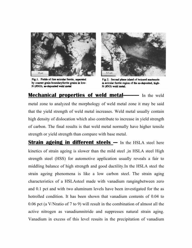
Microstructure of the as-deposited weld metal in the top layer of the welds
was ferrite, with a minor amount of second phase, Fig. 1. All types of ferrite
were present, i.e. grain boundary (GB) ferrite, side-plate ferrite and acicular
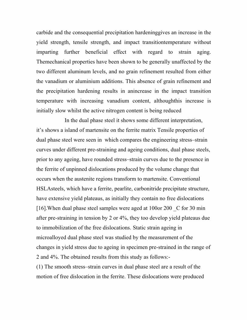
ferrite. The second phase in 'low-N' sample//NO was mainly bainite/pearlite,
and with increase of nitrogen content the second phase became martensitic,
Fig.2, its
amount increased as well. With more martensite as the second phase, the
dislocation density in ferrite of the top layer increased, and high density
dislocation configurations appeared in the heat affected weld beads of the
central and root portions of the welds. An increase of nitrogen content in C-
Mn steel weld metal results in a greater fraction of martensite in the weld
and consequently in a larger dislocation density in the ferrite.
The diffusivity of nitrogen is high than carbon, due to strain ageing more
nitrogen interact with dislocation interstitially dissolved nitrogen (and/or
carbon) during deformation, blue brittleness phenomena is occurred in steel
welded plate .
Mechanical properties of weld metal----------- In the weld
metal zone to analyzed the morphology of weld metal zone it may be said
that the yield strength of weld metal increases. Weld metal usually contain
high density of dislocation which also contribute to increase in yield strength
of carbon. The final results is that weld metal normally have higher tensile
strength or yield strength than compare with base metal.
Strain ageing in different steels --- In the HSLA steel here
kinetics of strain ageing is slower than the mild steel ,in HSLA steel High
strength steel (HSS) for automotive application usually reveals a fair to
middling balance of high strength and good ductility.In the HSLA steel the
strain ageing phenomena is like a low carbon steel. The strain aging
characteristics of a HSLAsteel made with vanadium rangingbetween zero
and 0.1 pct and with two aluminum levels have been investigated for the as
hotrolled condition. It has been shown that vanadium contents of 0.04 to
0.06 pct (a V/Nratio of 7 to 9) will result in the combination of almost all the
active nitrogen as vanadiumnitride and suppresses natural strain aging.
Vanadium in excess of this level resuits in the precipitation of vanadium
carbide and the consequential precipitation hardeninggives an increase in the
yield strength, tensile strength, and impact transitiontemperature without
imparting further beneficial effect with regard to strain aging.
Themechanical properties have been shown to be generally unaffected by the
two different aluminum levels, and no grain refinement resulted from either
the vanadium or aluminium additions. This absence of grain refinement and
the precipitation hardening results in anincrease in the impact transition
temperature with increasing vanadium content, althoughthis increase is
initially slow whilst the active nitrogen content is being reduced
In the dual phase steel it shows some different interpretation,
it’s shows a island of martensite on the ferrite matrix Tensile properties of
dual phase steel were seen in which compares the engineering stress–strain
curves under different pre-straining and ageing conditions, dual phase steels,
prior to any ageing, have rounded stress–strain curves due to the presence in
the ferrite of unpinned dislocations produced by the volume change that
occurs when the austenite regions transform to martensite. Conventional
HSLAsteels, which have a ferrite, pearlite, carbonitride precipitate structure,
have extensive yield plateaus, as initially they contain no free dislocations
[16].When dual phase steel samples were aged at 100or 200 _C for 30 min
after pre-straining in tension by 2 or 4%, they too develop yield plateaus due
to immobilization of the free dislocations. Static strain ageing in
microalloyed dual phase steel was studied by the measurement of the
changes in yield stress due to ageing in specimen pre-strained in the range of
2 and 4%. The obtained results from this study as follows:-
(1) The smooth stress–strain curves in dual phase steel are a result of the
motion of free dislocation in the ferrite. These dislocations were produced
by the volume change that occurs when the austenite regions transform to
martensite.
(2) The ageing treatment at 100 _C caused an increase in YS. This is due to
the formation of solute atom atmospheres around dislocations; at 200 _C
caused a reduction in the yield strength due to overageing resulted from
tempering that starts in martensite
.STRAIN AGEING IN WELD METAL:- The cause of the
embrittlement is the plastic strain accompanying shrinkage of welds which
can spread to surrounding base plate and heat affected zones. Since the
shrinkage strain occurs simultaneously with cooling from welding, it induces
strain aging and resultant loss of toughness. The effects of this type of strain
aging are greatly increased when weld discontinuities are present since they
provide strain concentrators in the weld or heat affected zone that can
exacerbate the strain aging effect. These discontinuities can be weld cracks
or lack of fusion in weld areas or welds placed over poor joint fit-up.
Experimental procedure:
Low- carbon steel sheet having carbon composition 0.13% and 0.8%
manganese was taken. The strips were cut in the rolling direction bunches of
some 10 pieces of strips were tagged by welding, the tensile specimen were
prepared by machining in the universal milling machine. The specimen
dimensions are shown in figure.
After that the specimen were given homogenised annealing at 950 C. The
specimen were tested in INSTRON 1195 in the following manner two
dummy samples were tested and total strain et at fracture was found out, the
assigned pre- strain values 3%, 6% and 9% were calculated from these (et)
values.
In the strip chart recorder of INSTRON 1195 machine straight lines
were drawn parallel to the tensile dummy curves. The number of such curves
was drawn corresponding to the no. of specimen to be pre-strained. The
specimen to be pre-strained fitted in the machine and simultaneously the
pen-stylus was exactly put at the origin pre-strain curve of stress-strain. Pen-
stylus move in proportion movement of the cross head. The movement of
pen-stylus touch the parallel line touch the assigned pre-strain and loading
was stopped then specimen was unloaded. After that the specimen was taken
out heated in oven under the oil bath with accuracy of +1 or -1C by the
thermocouple. The different specimens were aged at 120C.
The schedule for pre straining and ageing are shown in TABLE-1
TABLE-1
S No Percentage
pre strain
Temperature
of strain
ageing (C)
Time of
strain
ageing
1 3 120 2
2 9 120 2
3 3 160 2
4 9 160 2
5 3 120 6
6 9 120 6
7 3 160 6
8 9 160 6
9 6 140 4
RESULTS AND DISCUSSION ---- As mentioned previously the
welded or nonwelded tensile samples were prestrained & strainaged
according to the schedule shown in table – (1). The ∆y corresponding values
are shown against each of the strain ageing schedules.
By analyzing the ∆y, regression equation were formulated by applying of
Analyzing equation – (2), it can be seen that the extent of prestrain has got
negative influence over the ∆Y value. As revealed by its coefficient that is -
1.96 it indicates that the temperature of strain ageing has got positive
influence on ∆Y, which is a coefficient of +4.22. The time of strain ageing
has got also a positive influence on strain ageing behaviour as shown by that
is coefficient of +2.96 of the time of strain ageing
These coefficients explain the fact that temperature of strain ageing has got
more positive influence on ∆Y than the time of strain ageing. The interaction
coefficients are very small and negligible as compared with coefficients of
X1, X2 & X3.
On comparing equation – (2) & equation-(3) the following can be seen. The
b0 coefficient value of the welded sample is 16.175MPa in comparison to b0
(20.21MPa). This indicate that the extent of strain ageing in welded sample
is less due to this the ∆Y is less in welded sample. These factors are
attributed to the fact the dislocation density of weld metal is higher than
nonwelded sample.
As one of the requirement of strain ageing phenomena is low
initial dislocation density. The extent of strain ageing in nonwelded samples
indicated by its b0 value in equation – (2) is high, its comparison the extent
of strain ageing in welded sample is less as indicated by the b0 value in
equation –(3) , it’s state that the welded specimen have a high dislocation
density. The effect of other coefficient of equation – (3) are similar the
coefficient of equation – (2) .These means for welded samples also increased
the extent of prestrain reduces extent of strain ageing(∆Y) .Increase in the
strain-ageing temperature the value of ∆Y increased, increase the time of
ageing has also got influence on value of ∆Y. However the influence of
temperature of ageing is much more pronounced than the affect of time of
ageing.
This can be explained on the basis of influence of temperature on the
diffusion of carbon than the influence of time on the same. The strain ageing
is the result of locking of the dislocation by the carbon atom.
These results need verification by conducting further test on various
samples.
CONCLUSIONS –
1) Welded low carbon steel samples are found to respond strain ageing .
2) In both welded and non welded samples the effect of prestrain have
got negative influence on extent of strain ageing .
3) The temperature of strain ageing has got large positive influence on
the extent of strain ageing .
4) The time of strain ageing has positive influence on strain ageing
though its influence is less than that of the temperature of strain
ageing.
5) The extent of strain ageing in the welded sample is less than that in
the non-welded sample.
REFRENCES:----
1-Strain-Aging of Vanadium, Niobium or Titanium-Strengthened High-
Strength Low-Alloy Steels.,M.S.RASHID
2- D. V. WILSON and B. RUSSELL, Acta. Met. 8. 36 t 1960)
3- A. H. COTTRELL and B. A. BILBY, Proc. Phys. Sm. Lord.A62, 49
(1949).
4-A. H. COTTRELL and G. M. LEAK. J. Iron St. Inst. 172.301 (1952).
5-A. H. COTTRELL and A. T. CHURCHMAN, J. Iron St. Inst.162, 271
(1949).
6-Speich GR. Physical metallurgy of dual-phase steels. In: Kot RA, Bramfitt BL,editors. Fundamentals of dual-phase steels.Warrendale: AIME; 1981. p. 3–45 7-Influence of straining and ageing on the room temperature mechanical propertiesof dual phase steelSuleyman Gunduz *, Atilla Tosun 1Karabük University, Technical Education Faculty, Department of Materials, 78200 Karabük, Turkey 8-Influence of Post Weld Heat Treatment on the Dynamic Strain Aging of C-Mn SteelsD. Wagner, J.C. Moreno and C. Prioul 9-Cheng L., Bottger A., Mittemeijer E.J., Met. Trans. A, 23A (1992) 2737. 10-Fergusson P.,Jack K.H.,Quench-aging and strain-aging of nitrogen-ferrite, Proc. Heat Treatment Conf., Birmingham 1981, (The Metals Society) 158.- 11-MECHANICAL METALLURGY by G.H DIETER 12-RHYSICAL METALLURGY by VIJENDRE SINGHK. 13- Murata, H. Morise, M. Mitsutsuka, H. Haito, Transactions of the Iron and Steel Institute of Japan 24 (1984) B309.
14-Baird, J. D., “Strain Aging of Steel; A Critical Review,” Iron Steel, 36, 186-192, 326-34, 368-373, (May-Aug. 1963) 15-Baird, J. D., “The Effects of Strain Aging due to Interstitial Solutes on Mechanical properties of Metals,” Met. Rev., 5, 1-18 (Feb. 1971). 16-. Cottrell, A. H. and Bilby, B. A., “Dislocation Theory of Yielding and Strain Aging of Iron,” Proc. Phys. Soc. London, 62, 49-62 (1949) 17-. Wilson, D. V., and Russel, B., “The Contribution of Precipitation to Strain Aging in Low Carbon Steels,” Acta Mtall., 8, 468-479 (July 1960) 18-. Osborn, C. J., Scotchbrook, A. F., Stout, R. D., and Johnston, B. G., “The Effect of Plastic Strain and Heat Treatment,” Welding J., 14(8), Res. Suppls (1949) 19-. Rubin, A. I., Gross, J.H., and Stout, R. D., “Effect of Heat Treatment and Fabrication on Heavy Section Pressure Vessel Steels,” Welding J., 24(4), Res. Suppls (1959) 20-. Succop, L. N., Pense, A. W., and Stout, R. D., “The Effects of Warm Overstressing in Pressure Vessel Steel Properties,” Welding J., 49(8), Res. Suppls (1970) 21-. Herman, W. A., Erazo, M. A., DePatto, L. R.,Sekiwaza, M. and Pense, A. W., ”Strain Aging of Microalloyed Steels”, Welding Research Council Bulletin 322, April, 1987. 22-. Khristenko, I. N., "Effect of repeated strain aging on the tendency of carbon steel towards brittle failure," Metal Science and Heat Treatment (English Translation of Metallovedenie i Termicheskaya Obrabotka), 29, p.110 (1987) 23-. Sorsa, I. and Vierros, P., "The effect of welding on the mechanical properties of cold formed structural steels," Scandinavian Journal of Metallurgy, 16, p.134 (1987) 24-.Yurioka, N., "TMCP steels and Their Welding," Welding Research Abroad, V.43 (1997)
25-. Dobi, D., Kocak, M., et. al., "Evaluation of fracture properties of cold deformed 450 YS TMCP steel," Proceedings of the 13th International Conference on Offshore Mechanics and Arctic Engineering 3, p. 315 (1994) 26-. Ule, B., Vojvodic-G., J. and Lovrecic-S., M., "Effect of strain-aging on the fracture toughness of some structural grade steels in the nil-ductility temperature range," Canadian Metallurgical Quarterly, 35, p.159 (1996)