Strain Gage Module Model HM1520 Instruction Manual DECEMBER 2001 Solid state equipment has operational characteristics differing from those of electromechanical equipment. “Safety Guidelines for the Application, Installation and Maintenance of Solid State Controls” (Allen-Bradley Important User Information
Transcript
Strain Gage Module
Model HM1520
Instruction Manual
DECEMBER 2001
Solid state equipment has operational characteristics differing from thoseof electromechanical equipment. “Safety Guidelines for the Application,Installation and Maintenance of Solid State Controls” (Allen-Bradley
Important UserInformation
Publication SGI-1.1) describes some important differences between solidstate equipment and hard-wired electromechanical devices. Because ofthis difference, and also because of the wide variety of uses for solidstate equipment, all persons responsible for applying this equipmentmust satisfy themselves that each intended application of this equipmentis acceptable.
In no event will the Allen-Bradley Company or Helm InstrumentCompany be responsible or liable for indirect or consequential damagesresulting from the use or application of this equipment.
The examples and diagrams in this manual are included solely forillustrative purposes. Because of the many variables and requirementsassociated with any particular installation, the Allen-Bradley Company orHelm Instrument Company cannot assume responsibility or liability foractual use based on the examples and diagrams.
No patent liability is assumed by Allen-Bradley Company or HelmInstrument Company with respect to use of information, circuits,equipment, or software described in this manual.
Reproduction of the contents of this manual, in whole or in part, withoutwritten permission of the Allen-Bradley Company and Helm InstrumentCompany is prohibited.
Throughout this manual we use note to make you aware of safetyconsiderations.
ATTENTION: Identifies information about practices orcircumstances that can lead to property damage.Identifies information that is especially important forsuccessful application and understanding of the product.
Attentions help you:• identify a hazard• avoid the hazard• recognize the consequences
ATTENTION: Please check power supply ratingsbefore proceeding! Each tonnage moduleconsumes (+24, 65 mA +5, 150mA). Be sure to notoverload the power supply.
PLC, PLC2, PLC3, and PLC5 are registered trademarks of the Allen-Bradley Company, Inc.SLC, SLC500, PanelView, RediPANEL, Dataliner are trademarks of Allen-Bradley Company, Inc.IBM is a registered trademark of International Business Machines, Incorporated.StrainGage is a registered trademark of the Helm Instrument Company, Inc.
Table of ContentsStrain Gage Module
Table of ContentsStrainGage Load ModuleUser Manual
Table of ContentsStrainGage Load ModuleUser Manual
InitialSetupProcedures
System
Trouble-
Shooting
Guide
Read this preface to familiarize yourself with the rest of this manual. Thispreface covers the following topics:
• who should use this manual• the purpose of this manual• terms and abbreviations• conventions used in this manual• Allen-Bradley support
Use this manual if you are responsible for the design, installation, programming,or maintenance of an automation control system that used Allen-Bradley smalllogic controllers.
You should have a basic understanding of SLC 500 products. You shouldunderstand electronic process control and be able to interpret the ladder logicinstructions required to generate the electronic signals that control yourapplication. If you do not, contact your local Allen-Bradley representative for theproper training before using this product.
This manual is a learning and reference guide for the Helm StrainGage Module.It contains the information you need to install, wire, and use the module.
P-1
Purpose ofThis Manual
Who ShouldUse thisManual
Preface
Preface
Chapter Title Content
Preface Describes the purpose, background,and scope of this manual. Alsospecifies the audience for whom thismanual is intended and defines keyterms and abbreviations usedthroughout this book.
1 Overview Provides a hardware and systemoverview. Explains and illustratesthe components of the system.
2 Installation and Wiring Provides installation information andwiring guidelines.
3 Channel Configuration, Dataand
Status
Examines the channel configurationand the channel status word, andexplains how the module usesconfiguration data and generatesstatus during operation.
4 Ladder Programming Examples Gives an example of the ladder logicrequired to define the channel foroperation. Also includesrepresentative examples for uniquerequirements such as sample count,trend calculation, etc.
5 Troubleshooting Explains how to interpret and correctproblems that occur while using theload module.
A Specifications Provides physical, electrical,Environmental, and functionalSpecifications for the module.
B Ladder Program
C Panelview Screens Shows Panelview Screens andexplain their various functions.
P- 2
Contents of thisManual
Preface
The following documents contain information that may be helpful to you as youuse Allen-Bradley SLC products. To obtain a copy of any of the Allen-Bradleydocuments listed, contact your local Allen-Bradley office or distributor.
Selecting Discrete Input/Output Modules Compact Discrete Input/Output ModulesTechnical Data
1769-2.1
View power usage of expansion modules todetermine power supply requirements
Expansion Modules System Qualifier RA Website Download
End Cap Installation Compact I/O End Caps/TerminatorsInstallation Instructions
1769-5.16
A complete listing of current AutomationGroup documentation, including orderinginstructions. Also indicates whether thedocuments are available on CD-ROM or inmulti-languages
Automation Group Publication Index SD499
A glossary of industrial automation termsand abbreviations
Allen-Bradley Industrial AutomationGlossary
ICCG-7.1
An article on wire sizes and types forgrounding electrical equipment
National Electrical Code Published by theNational FireProtectionAssociation ofBoston, MA.
P-3
RelatedDocumentation
Preface
The following terms and abbreviations are used throughout this manual. For definitions of termsnot listed here refer to Allen-Bradley’s Industrial Automation Glossary, Publication ICCG-7.1.
Calibration - Procedure, performed by trained personnel, where machine or press isdynamically loaded to impact on load cells. A process of linearity measuring to determine theloading capacity of the machine.
Calibration Number - Amplification values established during machine calibration or pre-assigned on force load cells.
Channel - Refers to one of two, strain gage inputs available on the modules terminal block.
Chassis - A hardware assembly that houses devices such as I/O modules, adapter modules,processor modules, and power supplies.
Configuration Word - Contains the channel configuration information needed by the module toconfigure and operate each channel. Information is written to the configuration word throughthe logic supplied in your ladder program.
Data Word - A 16-bit integer that represent the value of the analog input channel. The channeldata word is valid only when the channel is enabled.
Gain - Amplification of an input signal.
Load/Force - Measurement of impact during a machine cycle. Sensors provide the input forthis measurement.
Look Window - Resolver or cam activated window, which allows specific degrees in a machinecycle to be processed.
Low Alarm Inhibit - Number of consecutive machine cycles where low alarm is inhibited. Usedin a process where machine cycles several times before running speed is established.
LSB - (Least Significant Bit) Refers to a data increment defined as the full scale range dividedby the resolution. The bit that represents the smallest value within a string of bits.
Monitor Parts Mode - Status condition used during production run. Sample and compare logicis enabled. On resolver based systems, tracking alarm limits can be enabled.
Multiplexer - A switching system that allows several input signals to share a common A/Dconverter.
Remote Configuration - A control system where the chassis can be located several thousandfeet from the processor chassis.
P-4
Terms andAbbrevia-tions
Preface
Resolution - The smallest detectable change in a measurement, typically expressed inengineering units (e.g. 0.15C) or as a number of bits. For example a 12-bit system has 4,096possible output states. It can therefore measure 1 part in 4096.
Resolver - Sometimes called encoder. Device attached on a machine to determine strokeposition. Sine/cosine based resolver required for Helm systems.
Reverse Load - Measurement of negative load/force being exerted on machine following thebreak-through of material. Also referred to as snap through.
Sample - Load/force values established from a series of machine cycles. Also defined asbenchmark.
Sample Count - User input value used to specify how many machine cycles to base the sampleon.
Sampling time - The time required by the A/D converter to sample an input channel.
Scale - Value used to describe the press/machine overall tonnage. Set for maximum value ofone channel. For example, settings for a 150 ton press = 75.
Setup Mode - Status condition of monitor typically enables during die setup. Machine capacityalarms are enabled. On resolver based systems, press curve alarm can be enabled. Thismode is also used during machine and resolver calibrations.
Status Word - Contains status information about the channel’s current configuration andoperational state. You can use this information in your ladder program to determine whetherthe channel data word is valid.
Target Load - A reference load established by the user. Used primarily during setup to improvesetup time.
Tolerance /Trend Alarm - User defined upper and lower control limits established during thesample and compare process. These limits are established on the peak load and will activatethe machine stop relay when exceeded.
Tracking Alarm - Requires resolver input. The sample and compare process is applied to theentire forming force based on user selected upper and lower control limits.
Trend Deviation - Percent of change, high and low, from sample value to current value.
Update Time - The time required for the module to sample and convert the input signals of allenables input channels and make the resulting data values available to the SLC processor.
P-5
Terms andAbbrevia-tions(continued)
Preface
The following conventions are used throughout this manual:
• Bulleted lists such as this one provide information, not procedural steps.• Numbered lists provide sequential steps or hierarchical information.
Contact your Helm representative or call Helm direct at 419-893-4356:
• sales and order support• product technical training• warranty support• support service agreements
Your Questions or Comments on this Manual
If you have any suggestions for how this manual could be made more useful to you, please sendus your ideas.
P-6
CommonTechniquesUsed in thisManual
ProductSupport
Preface
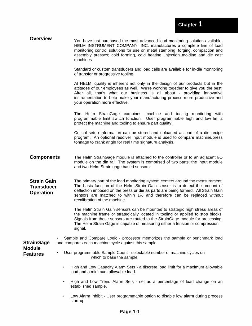
You have just purchased the most advanced load monitoring solution available.HELM INSTRUMENT COMPANY, INC. manufactures a complete line of loadmonitoring control solutions for use on metal stamping, forging, compaction andassembly presses; cold forming, cold heating, injection molding and die castmachines.
Standard or custom transducers and load cells are available for in-die monitoringof transfer or progressive tooling.
At HELM, quality is inherent not only in the design of our products but in theattitudes of our employees as well. We’re working together to give you the best.After all, that’s what our business is all about - providing innovativeinstrumentation to help make your manufacturing process more productive andyour operation more effective.
The Helm StrainGage combines machine and tooling monitoring withprogrammable limit switch function. User programmable high and low limitsprotect the machine and tooling to ensure part quality.
Critical setup information can be stored and uploaded as part of a die recipeprogram. An optional resolver input module is used to compare machine/presstonnage to crank angle for real time signature analysis.
The Helm StrainGage module is attached to the controller or to an adjacent I/Omodule on the din rail. The system is comprised of two parts; the input moduleand two Helm Strain gage based sensors.
The primary part of the load monitoring system centers around the measurement.The basic function of the Helm Strain Gain sensor is to detect the amount ofdeflection imposed on the press or die as parts are being formed. All Strain Gainsensors are matched to within 1% and therefore can be replaced withoutrecalibration of the machine.
The Helm Strain Gain sensors can be mounted to strategic high stress areas ofthe machine frame or strategically located in tooling or applied to stop blocks.Signals from these sensors are routed to the StrainGage module for processing.The Helm Strain Gage is capable of measuring either a tension or compressionsignal.
• Sample and Compare Logic - processor memorizes the sample or benchmark loadand compares each machine cycle against this sample.
• User programmable Sample Count - selectable number of machine cycles on which to base the sample.
• High and Low Capacity Alarm Sets - a discrete load limit for a maximum allowableload and a minimum allowable load.
• High and Low Trend Alarm Sets - set as a percentage of load change on anestablished sample.
• Low Alarm Inhibit - User programmable option to disable low alarm during processstart-up.
Page 1-1
Chapter 1
Overview
Components
Strain GainTransducerOperation
StrainGageModuleFeatures
The StrainGage module can be attached to the controller or to an adjacent I/Omodule before or after din rail mounting. It is a Class 1 module (uses eight inputwords and eight output words). It interfaces to strain gage based transducers(350ohm or 700ohm).
The module can accept input from two sensors. The module has no outputchannels. Module configuration requires manual and user programmable setup.
The StrainGage module receives and stores digitally converted analog data intoits image table for retrieval by processor. The module supports connections fromany combination of up to two strain gage sensors.
Any combination of Helm Strain Gage sensors can be used. Contact Helm foradditional information on the type and application of different sensor options.
The Helm module requires (1) input from a cam switch or a proximity sensor for establishing the peak look window
Page 1-2
HardwareOverview
Chapter 1
Alarm Status Display Fault Status - High and Low
Door Label Channel 1-Channel 2 calibrate switchWiring diagram for (2) sensor inputs
2. and 6.Channel Calibrate Switch
Three-position switch used for setup. AZ (Auto Zero ON) position is the normal runposition.CAL position (calibrate) is used with Gain potto set calibration numbers.OFF position is used with Balance pot to zerosensor.OFF position turns Auto Zero off.
1. and 5.Channel Gain Potentiometer
Used to set calibration numbers. Set three-position switch to CAL setting.
4. Recorder Output
Jacks for analog or track output of sensor data.One jack for each channel. Can be used withchart recorders or Helm Ramcorder™ datarecorder.
3. and 7.Channel Balance Potentiometer
Used to zero balance the sensor during setup.Set three-position switch to OFF position.
Gain SelectorHigh and Low CamJumper SettingLocated at BottomLeft Corner of Module
Black Jumper
Used to amplify the sensor input.This switch is factory set at highrange. Under normal operatingconditions, the setting should notbe changed. Personnelresponsible for the calibration ofthe Helm StrainGage modulemake the determination of therange setting during thecalibration process.
Page 1-3
HardwareFeatures
Chapter 1
1. Channel 1 Gain Pot
3. Channel 1 Balance Pot
2. Channel 1 Calibrate Switch
4. Recorder Output Jack
6. Channel 2 Calibrate Switch
5. Channel 2 Gain Pot
7. Channel 2 Balance Pot
8. Gain Select Jumper
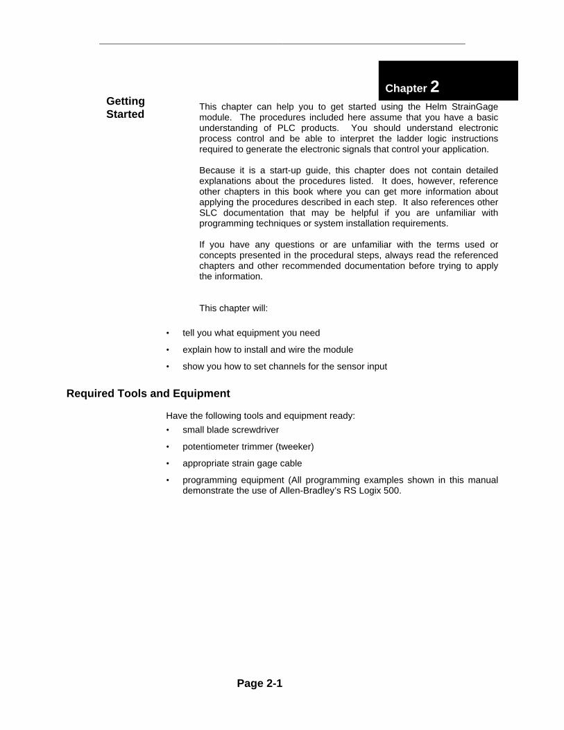
This chapter can help you to get started using the Helm StrainGagemodule. The procedures included here assume that you have a basicunderstanding of PLC products. You should understand electronicprocess control and be able to interpret the ladder logic instructionsrequired to generate the electronic signals that control your application.
Because it is a start-up guide, this chapter does not contain detailedexplanations about the procedures listed. It does, however, referenceother chapters in this book where you can get more information aboutapplying the procedures described in each step. It also references otherSLC documentation that may be helpful if you are unfamiliar withprogramming techniques or system installation requirements.
If you have any questions or are unfamiliar with the terms used orconcepts presented in the procedural steps, always read the referencedchapters and other recommended documentation before trying to applythe information.
This chapter will:
• tell you what equipment you need
• explain how to install and wire the module
• show you how to set channels for the sensor input
Required Tools and Equipment
Have the following tools and equipment ready:
• small blade screwdriver
• potentiometer trimmer (tweeker)
• appropriate strain gage cable
• programming equipment (All programming examples shown in this manualdemonstrate the use of Allen-Bradley’s RS Logix 500.
Page 2-1
Chapter 2GettingStarted
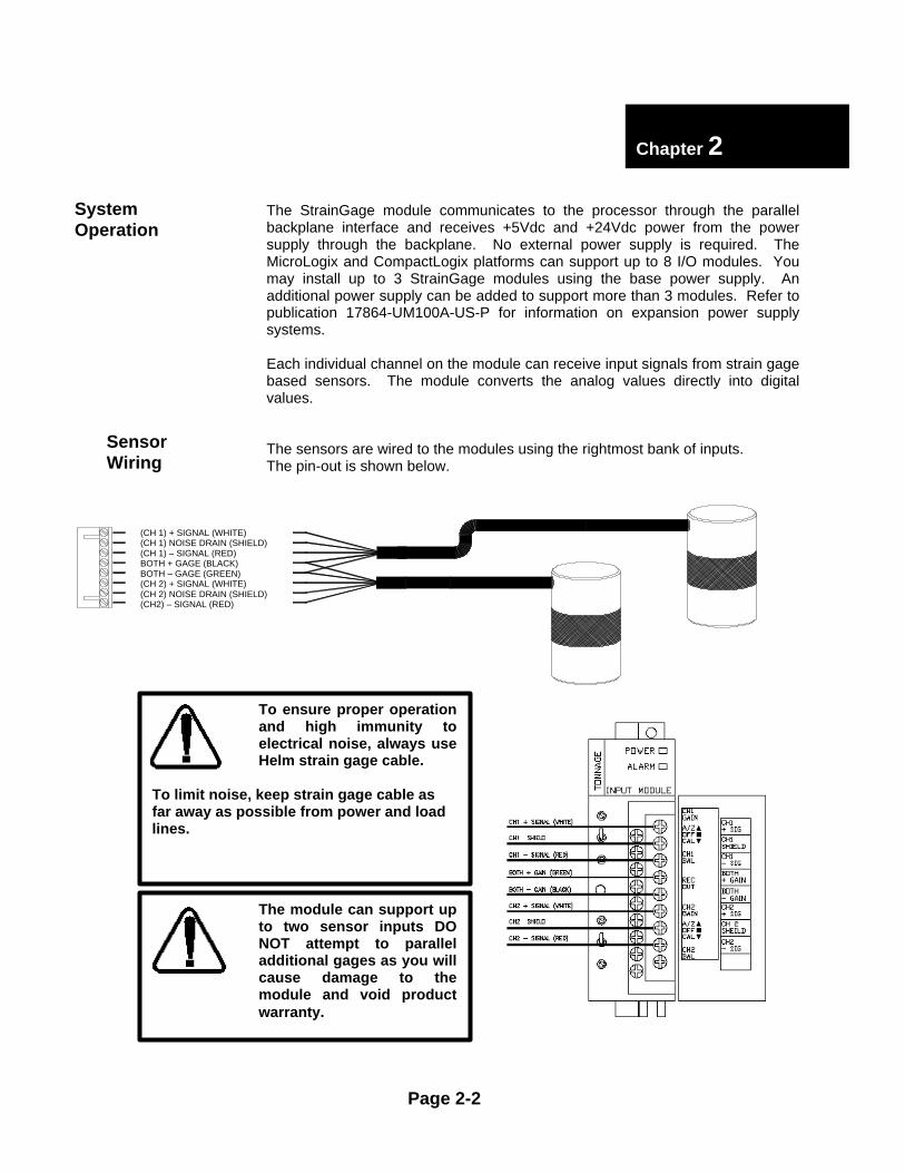
The StrainGage module communicates to the processor through the parallelbackplane interface and receives +5Vdc and +24Vdc power from the powersupply through the backplane. No external power supply is required. TheMicroLogix and CompactLogix platforms can support up to 8 I/O modules. Youmay install up to 3 StrainGage modules using the base power supply. Anadditional power supply can be added to support more than 3 modules. Refer topublication 17864-UM100A-US-P for information on expansion power supplysystems.
Each individual channel on the module can receive input signals from strain gagebased sensors. The module converts the analog values directly into digitalvalues.
The sensors are wired to the modules using the rightmost bank of inputs.The pin-out is shown below.
Page 2-2
SensorWiring
Chapter 2
SystemOperation
(CH 1) + SIGNAL (WHITE)(CH 1) NOISE DRAIN (SHIELD)(CH 1) – SIGNAL (RED)BOTH + GAGE (BLACK)BOTH – GAGE (GREEN)(CH 2) + SIGNAL (WHITE)(CH 2) NOISE DRAIN (SHIELD)(CH2) – SIGNAL (RED)
To ensure proper operationand high immunity toelectrical noise, always useHelm strain gage cable.
To limit noise, keep strain gage cable asfar away as possible from power and loadlines.
The module can support upto two sensor inputs DONOT attempt to paralleladditional gages as you willcause damage to themodule and void productwarranty.
This chapter explains how the StrainGage module and the processor communicateThrough the module's input and output image. It lists the preliminary setup and operationrequired before the module can function.
With RS Logic 500 software, verify the module ID code.
Product ID Code = 1Expansion General Configuration
Vendor ID = 3Product Type = 9Product Code = 1
Series/Major Rev/Minor Rev = B
No special I/O configuration (SPIO CONFIG) information is required. The module ID codeautomatically assigns the correct number of input and output words. The following memory mapshows how the output and input image tables are defined.
The 8 word output image (output from the CPU to the module) contains Information that you configure to define the way a specific channel will work. Example – If you want to configure channel 2 on the module located in slot 4 in the SLC chassis, your address would be O:4.2. (o = file type : =element delimiter 4=slot .=word delimiter 2=word)
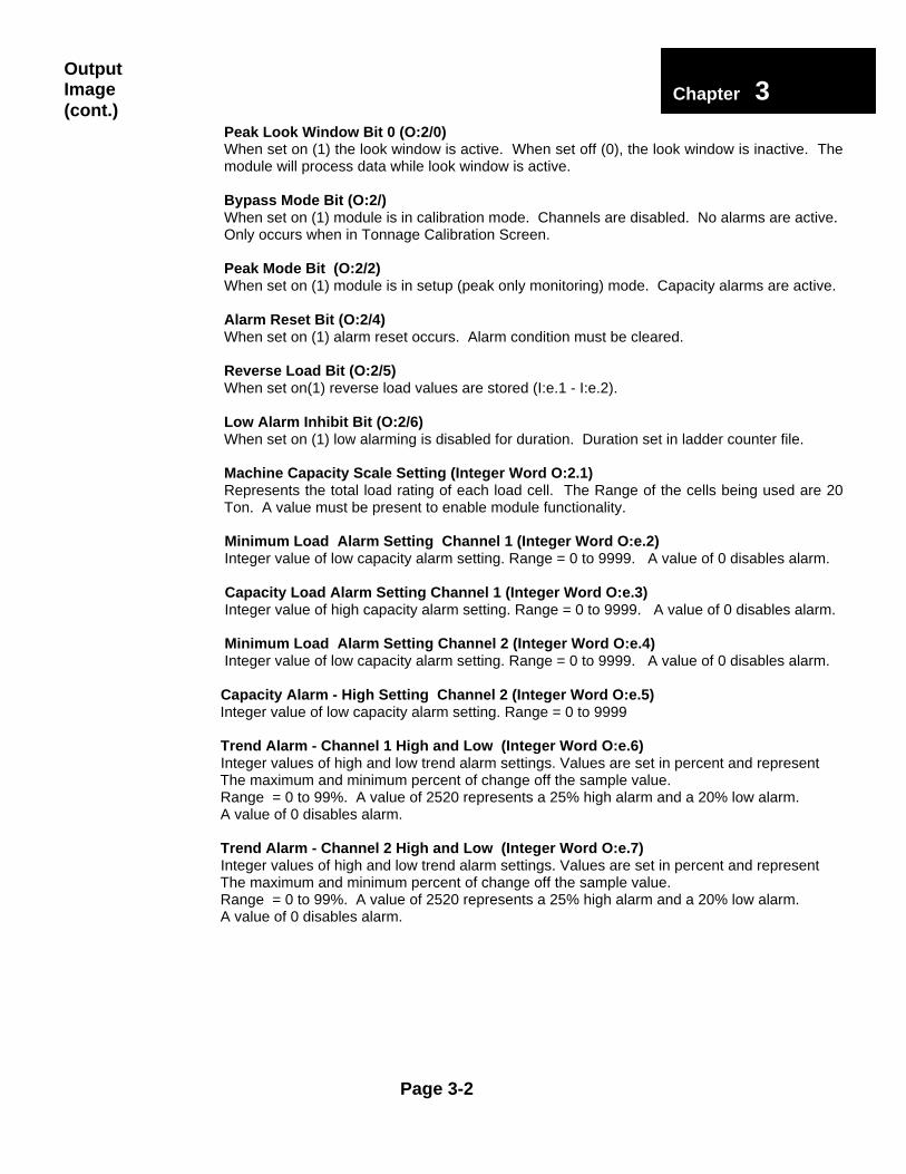
Peak Look Window Bit 0 (O:2/0)When set on (1) the look window is active. When set off (0), the look window is inactive. Themodule will process data while look window is active.
Bypass Mode Bit (O:2/)When set on (1) module is in calibration mode. Channels are disabled. No alarms are active.Only occurs when in Tonnage Calibration Screen.
Peak Mode Bit (O:2/2)When set on (1) module is in setup (peak only monitoring) mode. Capacity alarms are active.
Alarm Reset Bit (O:2/4)When set on (1) alarm reset occurs. Alarm condition must be cleared.
Reverse Load Bit (O:2/5)When set on(1) reverse load values are stored (I:e.1 - I:e.2).
Low Alarm Inhibit Bit (O:2/6)When set on (1) low alarming is disabled for duration. Duration set in ladder counter file.
Machine Capacity Scale Setting (Integer Word O:2.1)Represents the total load rating of each load cell. The Range of the cells being used are 20Ton. A value must be present to enable module functionality.
Minimum Load Alarm Setting Channel 1 (Integer Word O:e.2) Integer value of low capacity alarm setting. Range = 0 to 9999. A value of 0 disables alarm.
Capacity Load Alarm Setting Channel 1 (Integer Word O:e.3) Integer value of high capacity alarm setting. Range = 0 to 9999. A value of 0 disables alarm.
Minimum Load Alarm Setting Channel 2 (Integer Word O:e.4) Integer value of low capacity alarm setting. Range = 0 to 9999. A value of 0 disables alarm.
Capacity Alarm - High Setting Channel 2 (Integer Word O:e.5) Integer value of low capacity alarm setting. Range = 0 to 9999
Trend Alarm - Channel 1 High and Low (Integer Word O:e.6) Integer values of high and low trend alarm settings. Values are set in percent and represent The maximum and minimum percent of change off the sample value. Range = 0 to 99%. A value of 2520 represents a 25% high alarm and a 20% low alarm. A value of 0 disables alarm.
Trend Alarm - Channel 2 High and Low (Integer Word O:e.7) Integer values of high and low trend alarm settings. Values are set in percent and represent The maximum and minimum percent of change off the sample value. Range = 0 to 99%. A value of 2520 represents a 25% high alarm and a 20% low alarm. A value of 0 disables alarm.
Page 3-2
OutputImage(cont.)
Chapter 33
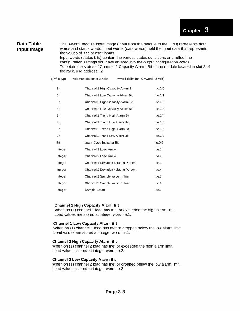
The 8-word module input image (input from the module to the CPU) represents data words and status words. Input words (data words) hold the input data that represents the values of the sensor inputs. Input words (status bits) contain the various status conditions and reflect the configuration settings you have entered into the output configuration words. To obtain the status of Channel 2 Capacity Alarm Bit of the module located in slot 2 of the rack, use address I:2
(I =file type : =element delimiter 2 =slot . =word delimiter 0 =word / 2 =bit)
Bit Channel 1 High Capacity Alarm Bit I:e.0/0
Bit Channel 1 Low Capacity Alarm Bit I:e.0/1
Bit Channel 2 High Capacity Alarm Bit I:e.0/2
Bit Channel 2 Low Capacity Alarm Bit I:e.0/3
Bit Channel 1 Trend High Alarm Bit I:e.0/4
Bit Channel 1 Trend Low Alarm Bit I:e.0/5
Bit Channel 2 Trend High Alarm Bit I:e.0/6
Bit Channel 2 Trend Low Alarm Bit I:e.0/7
Bit Learn Cycle Indicator Bit I:e.0/9
Integer Channel 1 Load Value I:e.1
Integer Channel 2 Load Value I:e.2
Integer Channel 1 Deviation value in Percent I:e.3
Integer Channel 2 Deviation value in Percent I:e.4
Integer Channel 1 Sample value in Ton I:e.5
Integer Channel 2 Sample value in Ton I:e.6
Integer Sample Count I:e.7
Channel 1 High Capacity Alarm Bit When on (1) channel 1 load has met or exceeded the high alarm limit. Load values are stored at integer word I:e.1.
Channel 1 Low Capacity Alarm Bit When on (1) channel 1 load has met or dropped below the low alarm limit. Load values are stored at integer word I:e.1.
Channel 2 High Capacity Alarm Bit When on (1) channel 2 load has met or exceeded the high alarm limit. Load value is stored at integer word I:e.2.
Channel 2 Low Capacity Alarm Bit When on (1) channel 2 load has met or dropped below the low alarm limit. Load value is stored at integer word I:e.2
Page 3-3
Chapter 33
Data TableInput Image
Channel 1 High Trend Alarm BitWhen on (1) channel 1 load has met or exceeded the high alarm percentage of sample.Load values are stored at integer word I:e.1.Percent of deviation of sample is stored at integer word I:e.5Percent of deviation of sample is stored at integer word I:e.5
Channel 1 Low Trend Alarm BitWhen on (1) channel 1 load has met or dropped below the low alarm percentage of sample.Load values are stored at integer word I:e.1.Percent of deviation of sample is stored at integer word I:e.5
Channel 2 High Trend Alarm BitWhen on (1) channel 2 load has met or exceeded the high alarm limit.Load value is stored at integer word I:e.2.Percent of deviation of sample is stored at integer word I:e.6
Channel 2 Low Trend Alarm BitWhen on (1) channel 2 load has met or dropped below the low alarm percentage of sample.Load value is stored at integer word I:e.2.Percent of deviation of sample is stored at integer word I:e.6
Channel 1 Load Value (I:e.1)Integer word represents peak load on channel 1 for current machine cycle.If Reverse Bit (O:e.0/5) is on (1) value is reverse load on channel 1 for current machine cycle.
Channel 2 Load Value (I:e.2)Integer word represents peak load on channel 2 for current machine cycle.If Reverse Bit (O:e.0/5) is on (1) value is reverse load on channel 2 for current machine cycle.
Note: If O:e.0/1 is set to 1 then A/D Value is integer word for calibration set.
Channel 1 Percent of Deviation (I:e.3)Integer word represents the percentage of change current peak load is to sample peak load.
Channel 2 Percent of Deviation (I:e.4)Integer word represents the percentage of change current peak load is to sample peak load.
Channel 1 Average Sample Value (I:e.5)Integer word represents the average of the sample load values on channel 1 in Tons.
Channel 2 Average Sample Value (I:e.6)Integer word represents the average of the sample load values on channel 2 in Tons.
Sample Counter (I:e.7)Counter used for number of Sample Count.
Page 3-4
Chapter 33
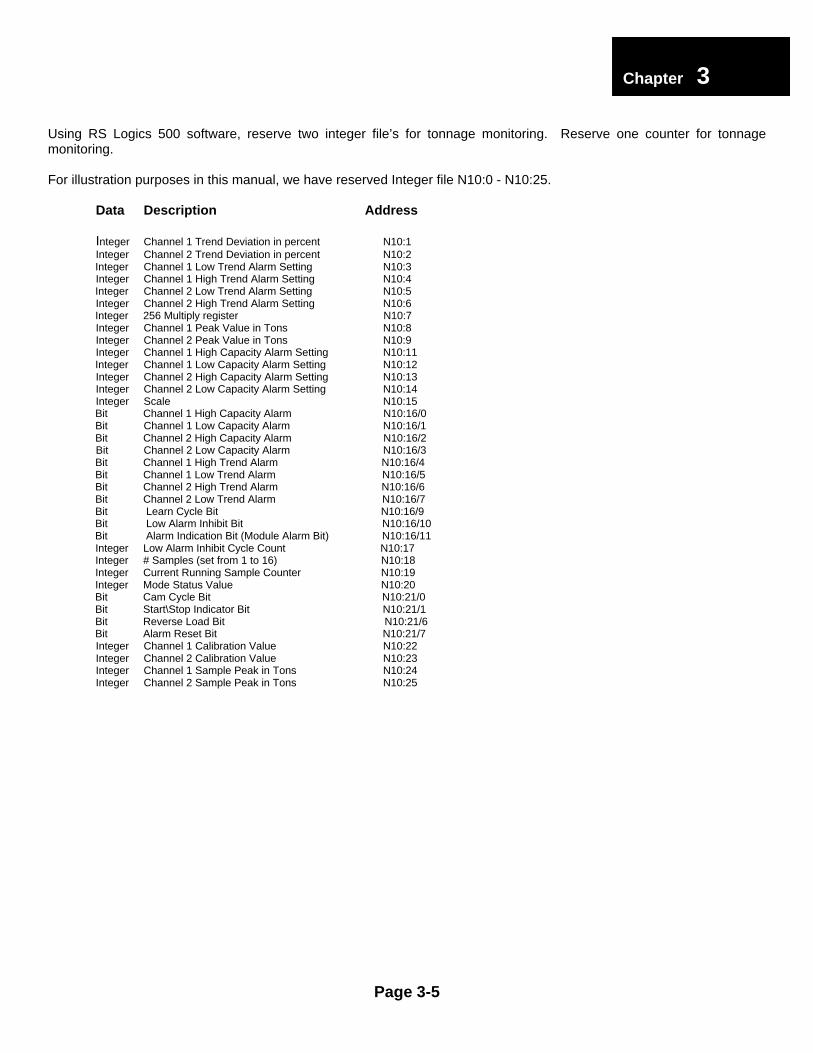
Using RS Logics 500 software, reserve two integer file’s for tonnage monitoring. Reserve one counter for tonnagemonitoring.
For illustration purposes in this manual, we have reserved Integer file N10:0 - N10:25.
Data Description Address
Integer Channel 1 Trend Deviation in percent N10:1Integer Channel 2 Trend Deviation in percent N10:2
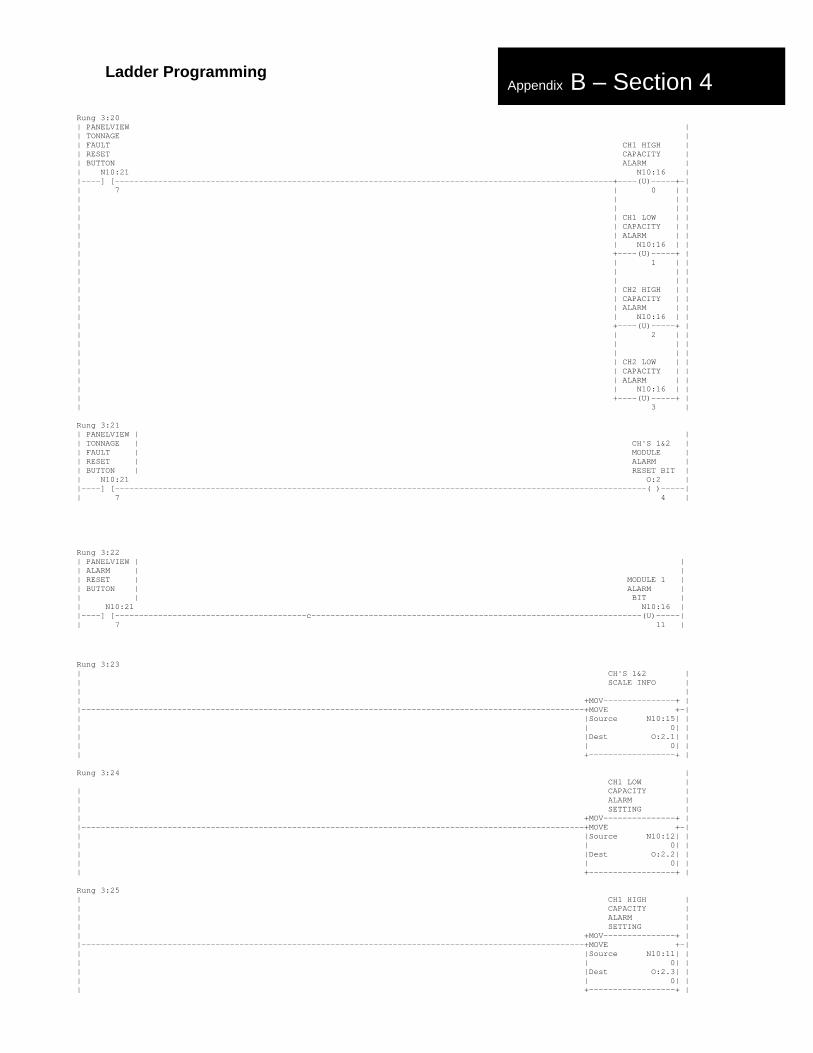
Bit Channel 1 High Capacity Alarm N10:16/0 Bit Channel 1 Low Capacity Alarm N10:16/1 Bit Channel 2 High Capacity Alarm N10:16/2
Bit Channel 2 Low Capacity Alarm N10:16/3 Bit Channel 1 High Trend Alarm N10:16/4 Bit Channel 1 Low Trend Alarm N10:16/5 Bit Channel 2 High Trend Alarm N10:16/6 Bit Channel 2 Low Trend Alarm N10:16/7 Bit Learn Cycle Bit N10:16/9 Bit Low Alarm Inhibit Bit N10:16/10 Bit Alarm Indication Bit (Module Alarm Bit) N10:16/11 Integer Low Alarm Inhibit Cycle Count N10:17 Integer # Samples (set from 1 to 16) N10:18 Integer Current Running Sample Counter N10:19 Integer Mode Status Value N10:20 Bit Cam Cycle Bit N10:21/0 Bit Start\Stop Indicator Bit N10:21/1 Bit Reverse Load Bit N10:21/6 Bit Alarm Reset Bit N10:21/7
Integer Channel 1 Calibration Value N10:22Integer Channel 2 Calibration Value N10:23Integer Channel 1 Sample Peak in Tons N10:24Integer Channel 2 Sample Peak in Tons N10:25
Page 3-5
Chapter 33
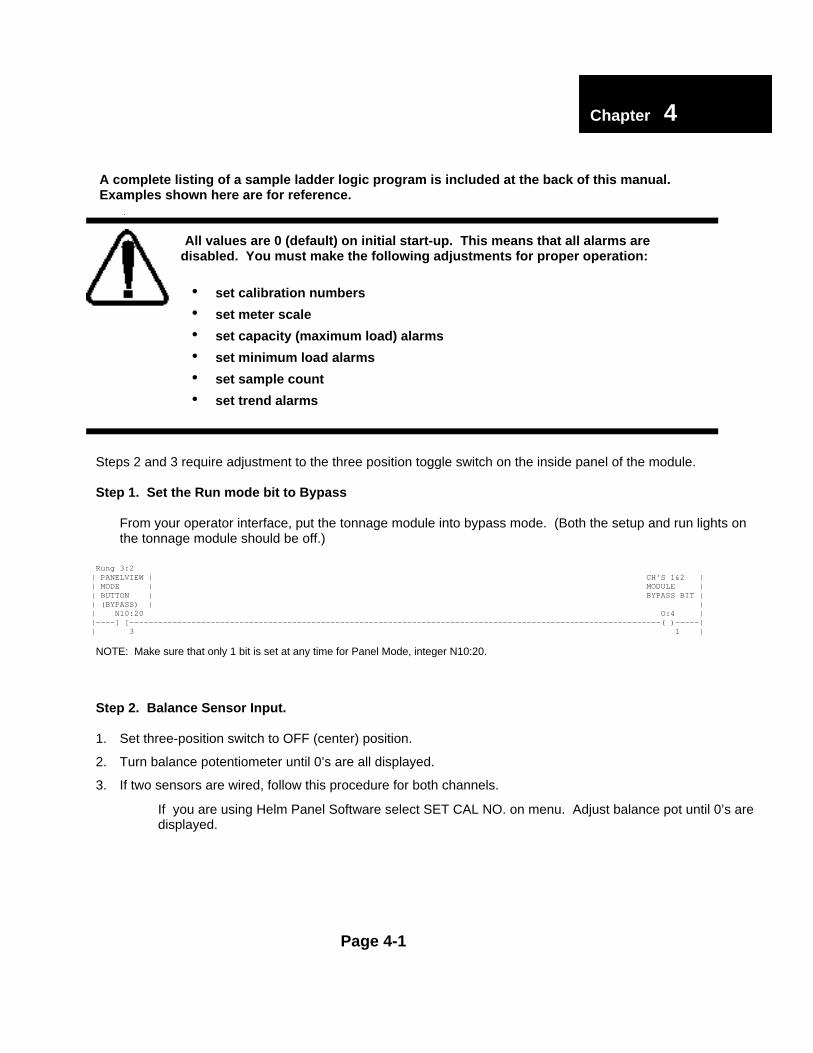
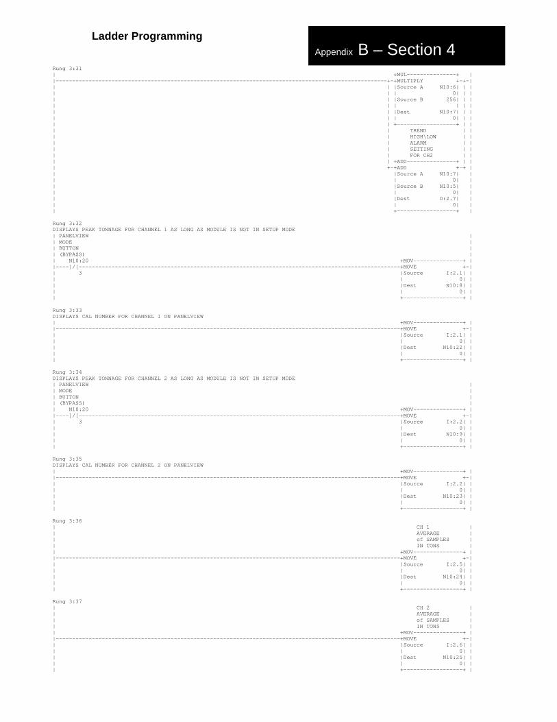
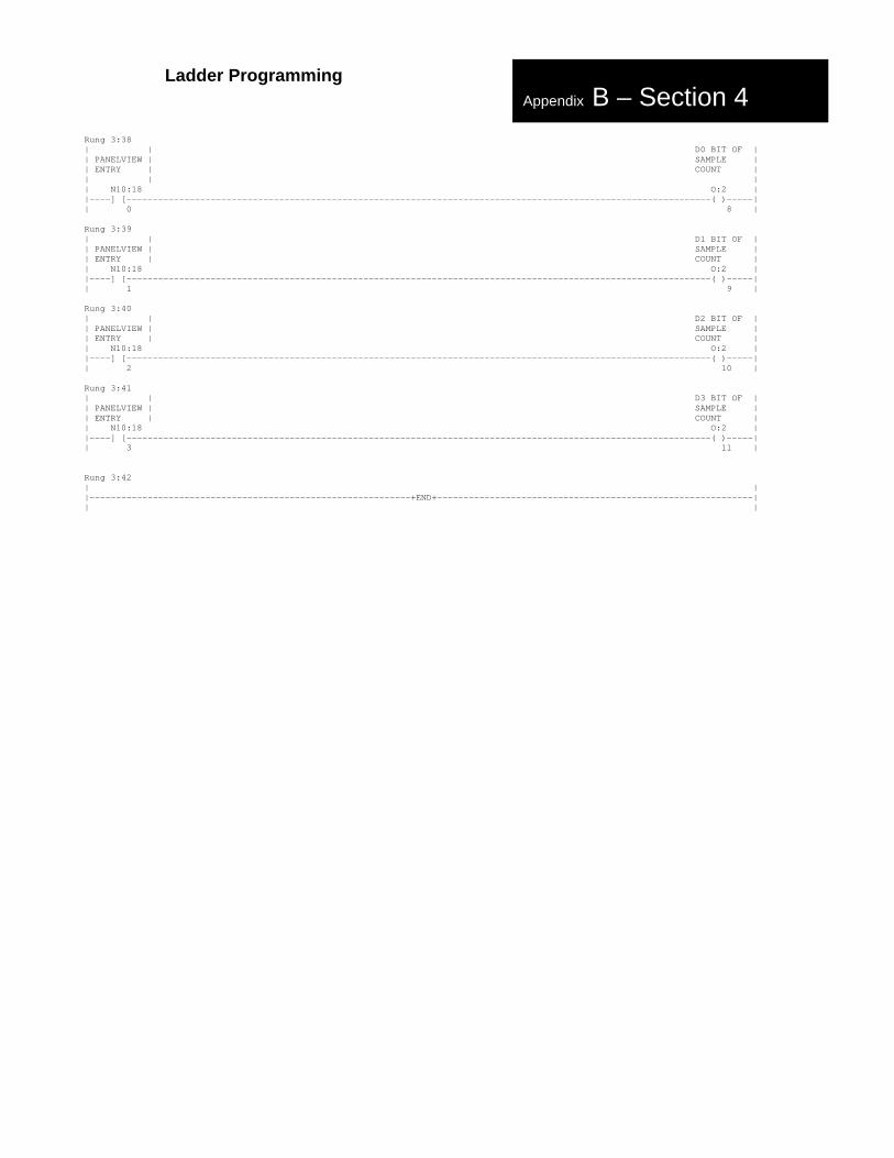
A complete listing of a sample ladder logic program is included at the back of this manual. Examples shown here are for reference.
All values are 0 (default) on initial start-up. This means that all alarms are disabled. You must make the following adjustments for proper operation:
• set calibration numbers
• set meter scale
• set capacity (maximum load) alarms
• set minimum load alarms
• set sample count
• set trend alarms
Steps 2 and 3 require adjustment to the three position toggle switch on the inside panel of the module.
Step 1. Set the Run mode bit to Bypass
⇒ From your operator interface, put the tonnage module into bypass mode. (Both the setup and run lights onthe tonnage module should be off.)
NOTE: Make sure that only 1 bit is set at any time for Panel Mode, integer N10:20.
Step 2. Balance Sensor Input.
1. Set three-position switch to OFF (center) position.
2. Turn balance potentiometer until 0’s are all displayed.
3. If two sensors are wired, follow this procedure for both channels.
⇒ If you are using Helm Panel Software select SET CAL NO. on menu. Adjust balance pot until 0’s aredisplayed.
Page 4-1
Chapter 34
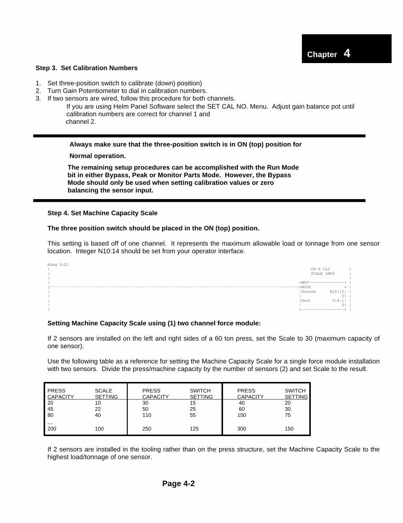
Step 3. Set Calibration Numbers
1. Set three-position switch to calibrate (down) position)2. Turn Gain Potentiometer to dial in calibration numbers.3. If two sensors are wired, follow this procedure for both channels.⇒ If you are using Helm Panel Software select the SET CAL NO. Menu. Adjust gain balance pot until
calibration numbers are correct for channel 1 and channel 2.
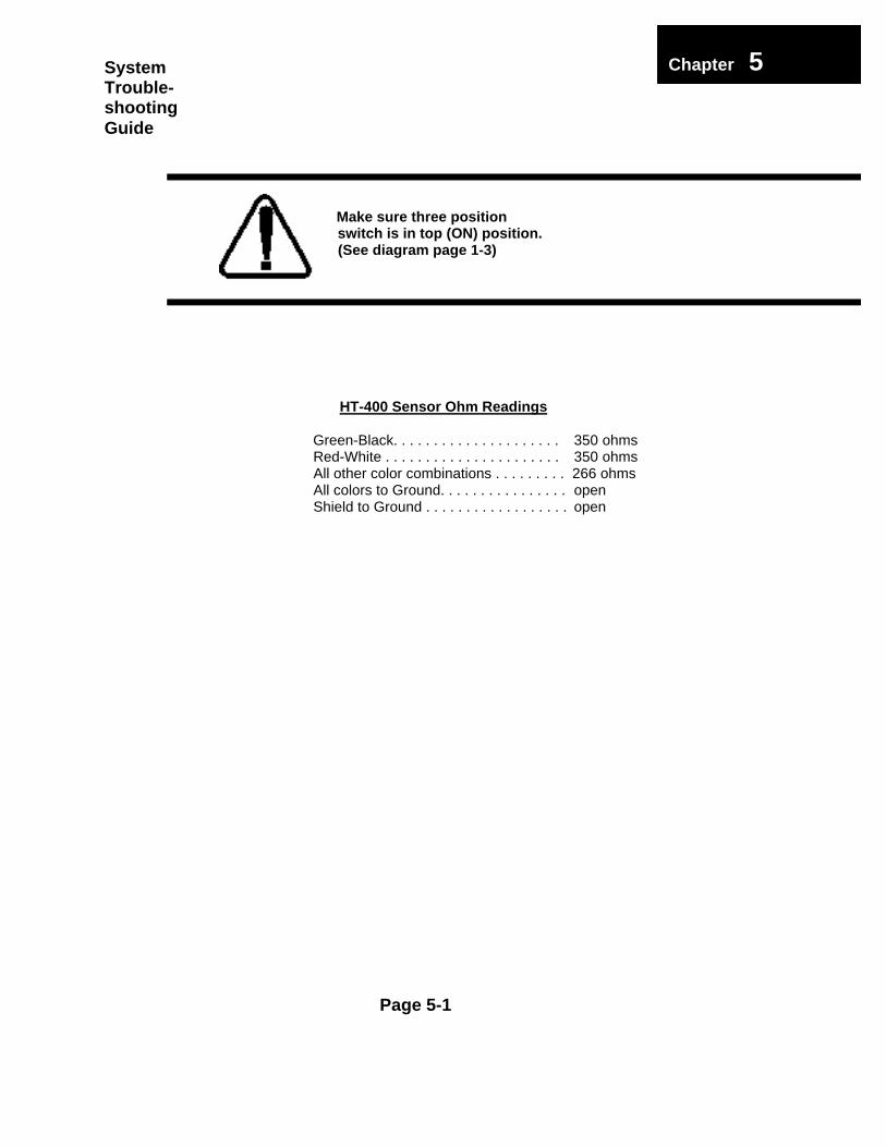
Always make sure that the three-position switch is in ON (top) position for
Normal operation.
The remaining setup procedures can be accomplished with the Run Mode bit in either Bypass, Peak or Monitor Parts Mode. However, the Bypass Mode should only be used when setting calibration values or zero balancing the sensor input.
Step 4. Set Machine Capacity Scale
The three position switch should be placed in the ON (top) position.
This setting is based off of one channel. It represents the maximum allowable load or tonnage from one sensorlocation. Integer N10:14 should be set from your operator interface.
Setting Machine Capacity Scale using (1) two channel force module:
If 2 sensors are installed on the left and right sides of a 60 ton press, set the Scale to 30 (maximum capacity ofone sensor).
Use the following table as a reference for setting the Machine Capacity Scale for a single force module installationwith two sensors. Divide the press/machine capacity by the number of sensors (2) and set Scale to the result.
If 2 sensors are installed in the tooling rather than on the press structure, set the Machine Capacity Scale to thehighest load/tonnage of one sensor.
Page 4-2
Chapter 34
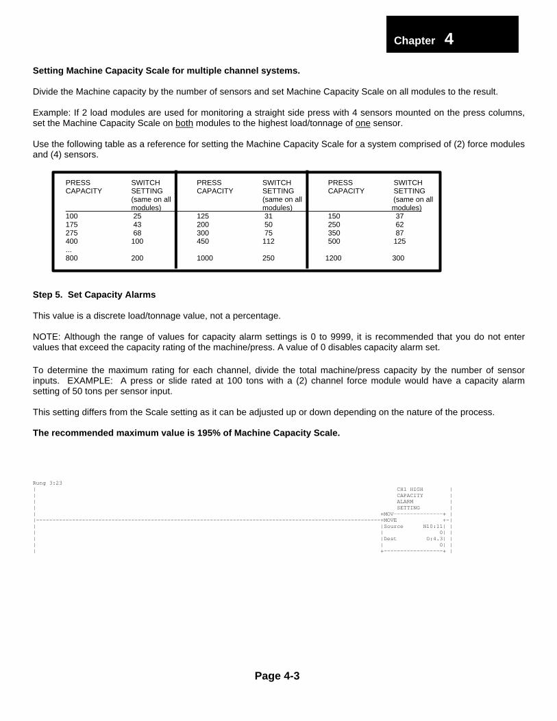
Setting Machine Capacity Scale for multiple channel systems.
Divide the Machine capacity by the number of sensors and set Machine Capacity Scale on all modules to the result.
Example: If 2 load modules are used for monitoring a straight side press with 4 sensors mounted on the press columns,set the Machine Capacity Scale on both modules to the highest load/tonnage of one sensor.
Use the following table as a reference for setting the Machine Capacity Scale for a system comprised of (2) force modulesand (4) sensors.
(same on all (same on all (same on all modules) modules) modules)100 25 125 31 150 37175 43 200 50 250 62275 68 300 75 350 87400 100 450 112 500 125...800 200 1000 250 1200 300
Step 5. Set Capacity Alarms
This value is a discrete load/tonnage value, not a percentage.
NOTE: Although the range of values for capacity alarm settings is 0 to 9999, it is recommended that you do not entervalues that exceed the capacity rating of the machine/press. A value of 0 disables capacity alarm set.
To determine the maximum rating for each channel, divide the total machine/press capacity by the number of sensorinputs. EXAMPLE: A press or slide rated at 100 tons with a (2) channel force module would have a capacity alarmsetting of 50 tons per sensor input.
This setting differs from the Scale setting as it can be adjusted up or down depending on the nature of the process.
The recommended maximum value is 195% of Machine Capacity Scale.
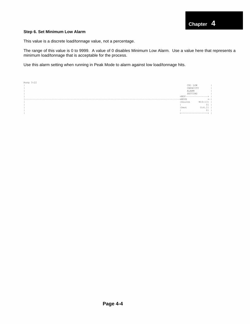
This value is a discrete load/tonnage value, not a percentage.
The range of this value is 0 to 9999. A value of 0 disables Minimum Low Alarm. Use a value here that represents aminimum load/tonnage that is acceptable for the process.
Use this alarm setting when running in Peak Mode to alarm against low load/tonnage hits.
The sample count is a user programmable parameter that tells the processor how many machine strokes arerequired to establish sample or benchmark load values. The value can range from 0 to 16. A value of 0invalidates the Monitor Parts mode. You should set Sample Count to a minimum of 1 to enable Monitor Partsmode.
Note: Each time you change Monitor Parts mode bit from ON to OFF, the sample value is cleared. Duringnormal operations, Monitor Parts mode is enabled when beginning a process run. If the process varies due tochange in material thickness, for example, it may be necessary to take a new sample.
The Trend Alarm settings are established as a percentage of allowable change in load. These percentagesare applied to the sample load values. There is a High Trend Alarm set and a Low Trend Alarm set for eachchannel. The limits can range from 0 to 99%. A setting of 0 disables the alarm.
These alarms are active when the Monitor Parts Mode bit is ON. When monitor parts mode is enabled, thesample process takes place.
Example: Monitor Parts mode is enabled with a sample count of 4 and high and low Trend Alarms set at10%. The load generated on the next 4 machine cycles is averaged to obtain the sample value for eachchannel. A sample of 30 tons is calculated for channel 1 and a sample of 40 tons is calculated for channel 2.
If any succeeding machine stroke develops tonnage of 33 (10% of 30 = 3 tons) or higher on channel 1 theHigh Trend Alarm is reached and the alarm bit is turned ON. If tonnage falls to 27, the Low Trend Alarm setis reached and the alarm bit is turned ON.
You have completed the basic setup and the module is operational.
Page 4-6
Chapter 34
Mode StatusThe three modes are Bypass, Peak, Monitor Parts
Bypass ModeUsed for module setup and at the time of calibration. All alarms are disabled in bypass mode.
In Peak Mode operation, the high capacity alarms and the low minimum alarms are active. There is nosample calculation and high and low Trend alarms are inactive. This mode is used primarily during machinesetup operations.
When Monitor Parts Mode bit is turned ON, the sample is calculated based on the number of sample countsand the high and low Trend alarms are activated. The High Capacity and Low Minimum Alarms remainactive.
The panel function switch in these 3 rungs need to be a button on your operator interface (multistatepushbutton with 3 states) that writes 3 different values to tag N7:6
1st state - 8 bypass2nd state - 16 peak3rd state - 32 monitor parts
Page 4-7
AdditionalApplicationNotes
Chapter 34
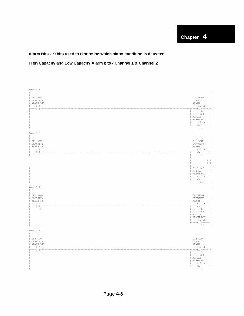
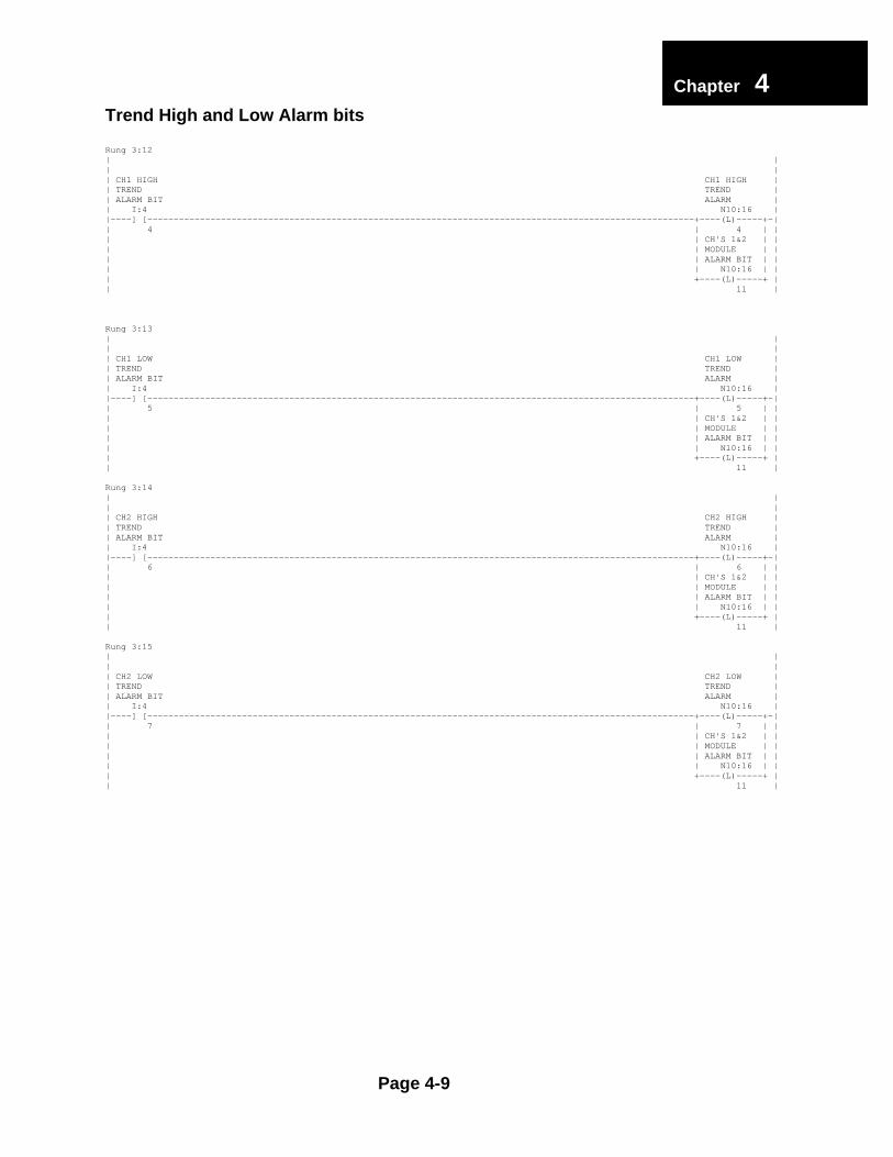
Alarm Bits - 9 bits used to determine which alarm condition is detected.
High Capacity and Low Capacity Alarm bits - Channel 1 & Channel 2
Rung 2:13CAUSES EITHER E-STOP OR TOP STOP RELAY TO DROP OUT WHEN THERE IS A TONNAGEFAULT| CH'S 1&2 | E-STOP OR || MODULE | TOP STOP || ALARM BIT | RELAY || N10:16 O:2 ||----]/[---------------------------------------------------------------------------------------------------------------( )-----|| 11 0 |
NOTE: Customer mapped in output module.
Page 4-10
Chapter 34
Low Alarm Inhibit
In some processes it may be necessary to inhibit the Low Capacity alarm during machine ramp up. Usethe following example to set the low alarm inhibit bit based on a counter.
with press stoppedand remains clearedAlarm can be reset
Reconnect sensors.
take ohm readingsDisconnect sensors and
at terminal stripCheck sensor connections
on all channelsCheck zero balance
press stoppedor remain reset w/
Alarm does not reset
Alarmin Peak Mode
Page 5-3
Chapter 35SystemTrouble-shootingGuide(contd.)
Parallelparallel
Correct problem
Out of
Check press parallelism
Capacity alarm fired
Tolerance alarm fired
No alarm
None
No
Yes
Yes
Correct problem
run pressRemove slug and
press or die damagecollar, linkage, or otherCheck for broken shear
in dieCheck for slug build-up
Alarm does resetwith press stopped
press runningRe sample with
Set mode to Peak
Alarm does not resetwith press stopped
Monitor Parts ModeAlarm in
Page 5-4
Chapter 35SystemTrouble-shootingGuide(contd.)
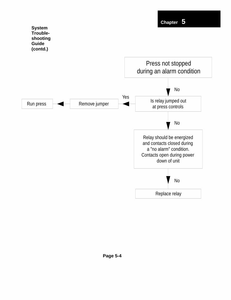
down of unitContacts open during power
YesRemove jumperRun press
a "no alarm" condition.and contacts closed duringRelay should be energized
No
No
No
Is relay jumped outat press controls
Replace relay
during an alarm conditionPress not stopped
Page 5-5
Chapter 35SystemTrouble-shootingGuide(contd.)
None
None Parallel
ParallelOK
Parallel
in dieCheck for slug build-up
YesRemove slug& run press
in dieCheck for slug build-up
YesRemove slug& run press of press
Check the parallelism
parallel
Out of
problemCorrect
of pressCheck the parallelism
parallel
Out of
problemCorrect
deformed shear collarCheck for broken or
Broken
wear collarReplace
deformed shear collarCheck for broken or
Broken
wear collarReplace
Tonnage readings HIGHon adjacent corners
Tonnage readings HIGHon one corner
parallel
Out of
Yes
BrokenReplace
wear collar
Correctproblem
& run pressRemove slug Check for slug build-up
in die
of pressCheck the parallelism
deformed shear collarCheck for broken or
on diagonal cornersTonnage readings HIGH
distributionUneven load
Page 5-6
Chapter 35SystemTrouble-shootingGuide(contd.)
None
Check for pressproblem
Yes
Correct problem
Correct problem
Correct problem
YesNone
Yes
in stockCheck for variation
problemCheck for die
Erratic readings
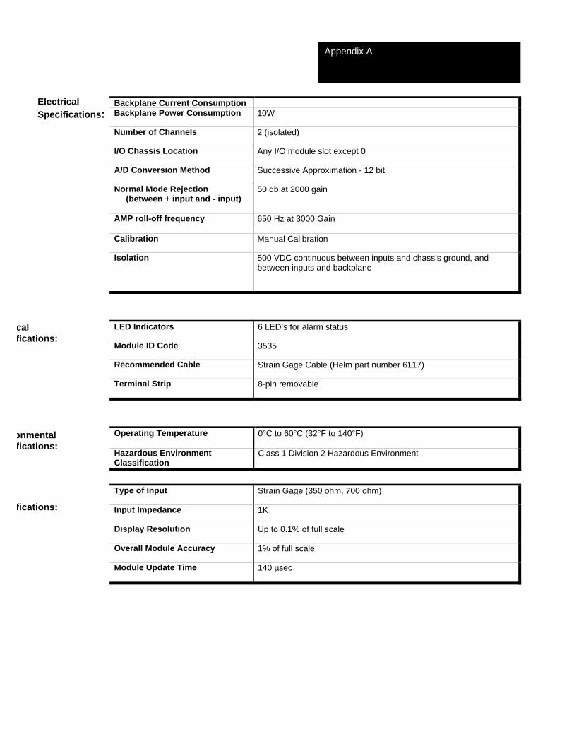
Backplane Current ConsumptionBackplane Power Consumption 10W
Number of Channels 2 (isolated)
I/O Chassis Location Any I/O module slot except 0
A/D Conversion Method Successive Approximation - 12 bit
Normal Mode Rejection (between + input and - input)
50 db at 2000 gain
AMP roll-off frequency 650 Hz at 3000 Gain
Calibration Manual Calibration
Isolation 500 VDC continuous between inputs and chassis ground, andbetween inputs and backplane
LED Indicators 6 LED’s for alarm status
Module ID Code 3535
Recommended Cable Strain Gage Cable (Helm part number 6117)
Terminal Strip 8-pin removable
Operating Temperature 0°C to 60°C (32°F to 140°F)
Hazardous EnvironmentClassification
Class 1 Division 2 Hazardous Environment
Type of Input Strain Gage (350 ohm, 700 ohm)
Input Impedance 1K
Display Resolution Up to 0.1% of full scale
Overall Module Accuracy 1% of full scale
Module Update Time 140 µsec
ElectricalSpecifications:
calfications:
onmentalfications:
fications:
Appendix A
Page A-1 Ladder Programming Summary:
Appendix B, Section 2 - ladder interface for a 2 channel tonnage system
Appendix B, Section 3 - ladder interface for a 4 channel tonnage system
Appendix B, Section 4 - ladder file required for every StrainGage module in your plc. Ex: 2 tonnage modules = 2 files, each with a different integer table and different I/O addresses.
Note: 1.) For 2 channel system - use ladder in sections 2 & 4
2.) For 4 channel system - use ladder in sections 3 and have 2 files same as section 4, the file for CH’S 1 & 2 uses integer N10 and file and file for CH’S 3 & 4 uses integer N11.
3.) If creating a system with more than 2 StrainGage modules, use Appendix B, Section 3 as a reference. This file has all the common integers needed for each StrainGage mod
Appendix B – Section 1LadderProgramming
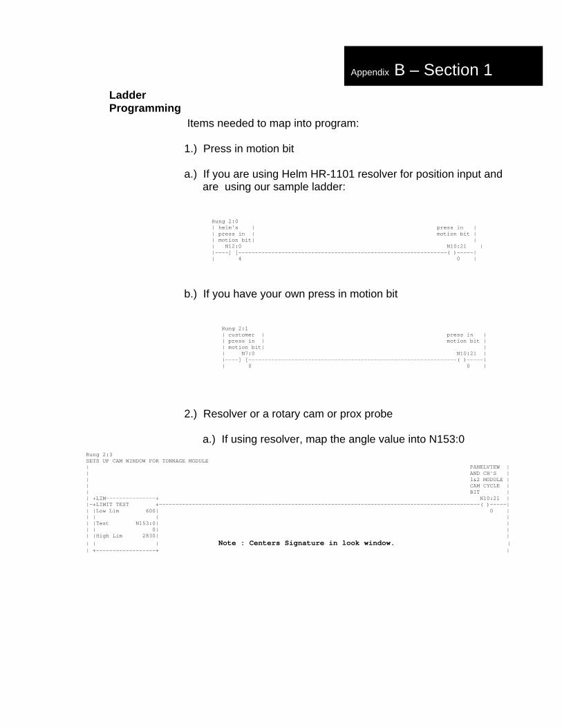
Items needed to map into program:
1.) Press in motion bit
a.) If you are using Helm HR-1101 resolver for position input and are using our sample ladder:
Rung 2:0 | helm's | press in | | press in | motion bit | | motion bit| | | N12:0 N10:21 | |----] [---------------------------------------------------------------( )-----| | 4 0 |
b.) If you have your own press in motion bit
Rung 2:1 | customer | press in | | press in | motion bit | | motion bit| | | N7:0 N10:21 | |----] [---------------------------------------------------------------( )-----| | 0 0 |
2.) Resolver or a rotary cam or prox probe
a.) If using resolver, map the angle value into N153:0Rung 2:3SETS UP CAM WINDOW FOR TONNAGE MODULE| PANELVIEW || AND CH'S || 1&2 MODULE || CAM CYCLE || BIT || +LIM---------------+ N10:21 ||-+LIMIT TEST +-------------------------------------------------------------------------------------------------( )-----|| |Low Lim 600| 0 || | | || |Test N153:0| || | 0| || |High Lim 2830| |
Rung 2:3SETS UP CAM WINDOW FOR TONNAGE MODULE| PANELVIEW || AND CH'S || 1&2 MODULE || CAM CYCLE || BIT || +LIM---------------+ N10:21 ||-+LIMIT TEST +-------------------------------------------------------------------------------------------------( )-----|| |Low Lim 600| 0 || | | || |Test N153:0| || | 0| NOTE: CENTERS SIGNITURE IN LOOKWINDOW || | | || |High Lim 2830| || | | || +------------------+ |
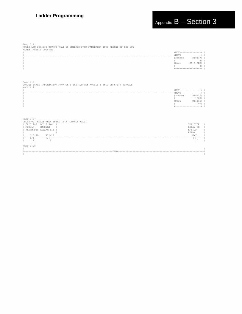
Rung 2:4MOVES LOW ALARM INHIBIT COUNTS ENTERED FROM PANELVIEW INTO THE PRESET OF THELOW ALARM INHIBIT COUNTER| +MOV---------------+ ||---------------------------------------------------------------------------------------------------------+MOVE +-|| |Source N10:17| || | 0| || |Dest C5:5.PRE| || | 4| || +------------------+ |
Rung 2:13CAUSES EITHER E-STOP OR TOP STOP RELAY TO DROP OUT WHEN THERE IS A TONNAGEFAULT| CH'S 1&2 | E-STOP OR || MODULE | TOP STOP || ALARM BIT | RELAY || N10:16 O:7 ||----]/[---------------------------------------------------------------------------------------------------------------( )-----|| 11 0 |
Rung 3:27DROPS OUT RELAY WHEN THERE IS A TONNAGE FAULT| CH'S 1&2 |CH'S 3&4 | TOP STOP || MODULE |MODULE | RELAY OR || ALARM BIT |ALARM BIT | E-STOP || | RELAY || N10:16 N11:16 O:7 ||----]/[--------]/[----------------------------------------------------------------------------------------------------( )-----|| 11 11 0 |