HAL Id: hal-01007326 https://hal.archives-ouvertes.fr/hal-01007326 Submitted on 27 Sep 2017 HAL is a multi-disciplinary open access archive for the deposit and dissemination of sci- entific research documents, whether they are pub- lished or not. The documents may come from teaching and research institutions in France or abroad, or from public or private research centers. L’archive ouverte pluridisciplinaire HAL, est destinée au dépôt et à la diffusion de documents scientifiques de niveau recherche, publiés ou non, émanant des établissements d’enseignement et de recherche français ou étrangers, des laboratoires publics ou privés. Strain-Induced Crystallization of Natural Rubber: a Review of X-ray Diffraction Investigations Bertrand Huneau To cite this version: Bertrand Huneau. Strain-Induced Crystallization of Natural Rubber: a Review of X-ray Diffraction Investigations. Rubber Chemistry and Technology, American Chemical Society, 2011, 84 (3), pp.425- 452. 10.5254/1.3601131. hal-01007326
Transcript
HAL Id: hal-01007326https://hal.archives-ouvertes.fr/hal-01007326
Submitted on 27 Sep 2017
HAL is a multi-disciplinary open accessarchive for the deposit and dissemination of sci-entific research documents, whether they are pub-lished or not. The documents may come fromteaching and research institutions in France orabroad, or from public or private research centers.
L’archive ouverte pluridisciplinaire HAL, estdestinée au dépôt et à la diffusion de documentsscientifiques de niveau recherche, publiés ou non,émanant des établissements d’enseignement et derecherche français ou étrangers, des laboratoirespublics ou privés.
Strain-Induced Crystallization of Natural Rubber: aReview of X-ray Diffraction Investigations
Bertrand Huneau
To cite this version:Bertrand Huneau. Strain-Induced Crystallization of Natural Rubber: a Review of X-ray DiffractionInvestigations. Rubber Chemistry and Technology, American Chemical Society, 2011, 84 (3), pp.425-452. �10.5254/1.3601131�. �hal-01007326�
STRAIN-INDUCED CRYSTALLIZATION OF NATURAL RUBBER: A
REVIEW OF X-RAY DIFFRACTION INVESTIGATIONS
BERTRAND HUNEAU
LUNAM UNIVERSITE, ECOLE CENTRALE DE NANTES, INSTITUT DE RECHERCHE EN GENIE CIVIL ET MECANIQUE
(GEM), UMR CNRS 6183, BP 92101, F-44321 NANTES CEDEX 3, FRANCE
ABSTRACTStrain-induced crystallization of natural rubber was discovered in 1925 by the means of x-ray diffraction and has
been widely investigated by this technique until today. The studies devoted to the structure of the crystalline phase of natural rubber are first reviewed. This structure is strongly anisotropic and can be related to the exceptionally good strength and fatigue properties of this material. The relationships between strain-induced crystallization of natural rubber and its mechanical response, during static or tension-retraction tests, are also reviewed and discussed; in particular, the hysteresis of the stress-strain curve is mainly explained by strain-induced crystallization. The kinetics of crystallization under both static and cyclic deformation is also discussed, as well as the influence of different factors, depending either on material composition (crosslink density, carbon black fillers) or on external parameters (temperature, strain rate. . . )
I. INTRODUCTION
Natural rubber (NR), cis-1,4-polyisoprene, is a widely used material in elastomeric partsbecause it combines very large elastic strain with a high tensile strength and a remarkable crackgrowth resistance.1, 2 These outstanding properties are partly attributed to the strain-inducedcrystallization (SIC) phenomenon that occurs in NR. In particular, the induced crystallites aresupposed to slow down, deviate, and even stop crack growth, either for static or cyclic loadingconditions.3 This ability to crystallize under strain is often explained by the high regularity of
1
the macromolecular structure, i.e., its percentage of chains being in cis-configuration, which isvery close to 100% in NR. Synthetic isoprene rubber (IR) exhibits a lower crystallinity than NRbecause of the lower regularity of the macromolecular structure, even though it can contain morethan 98% of chains in cis-configuration. Some authors also argue that the non-rubber componentsin NR (6 wt. % of proteins and lipids) play a major role in its excellent mechanical properties,because they enhance its capacity to crystallize.4, 5
SIC was discovered in 1925 by Katz,6 who was the first to show the x-ray diffractionpattern of a uniaxially stretched NR. Note that unstrained NR can also crystallize by cooling;this phenomenon is called thermally induced crystallization (TIC), or “cold” crystallization andwas studied for example by Bekkedahl and Wood in the 1940s.7, 8 They used the volume changetechnique to study the kinetics of this kind of crystallization. In particular, they established thatthe maximal crystallization rate of unstretched rubber takes place at approximately − 25 ◦C,whereas at room temperature no crystallization occurs.
Many experimental techniques were used over the years to investigate the crystallization ofNR under strain: volume change,7–10 stress relaxation,9 transmission electron microscopy,11, 12
differential scanning calorimetry,13 birefringence,14, 15 nuclear magnetic resonance,5, 16 orRaman spectroscopy.17 Nevertheless, the present review will be limited to wide-angle x-raydiffraction (WAXD) studies of SIC, from the pioneering works to the most recent studies.The reader interested in theoretical and thermodynamical approaches is invited to consult theworks of Flory,18 Treloar,19 or Roberts and Mandelkern.20 Moreover, one should notice thatsome aspects of SIC were already reviewed, for example, by Magill21 and more recently byTosaka.22
After the discovery of Katz, a large number of WAXD studies were performed especiallyduring the 1930s and the 1940s. Some of them were dedicated to the crystal structure of NR, butrapidly some engineering studies investigated more deeply SIC of NR. In the last 10 years, thistopic has been updated by the use of synchrotron radiation, which permits to perform real-timeexperiments. In Section II, the crystal structure of NR and its lattice parameters will be presented,as well as the crystallites morphology. In Section III, the relationships between SIC and themechanical response of NR will be detailed especially during a tension-retraction cycle. Finally,Section IV will present different factors that affect SIC.
II. THE CRYSTALLINE PHASE OF NATURAL RUBBER
A. CRYSTALLOGRAPHIC STRUCTURE
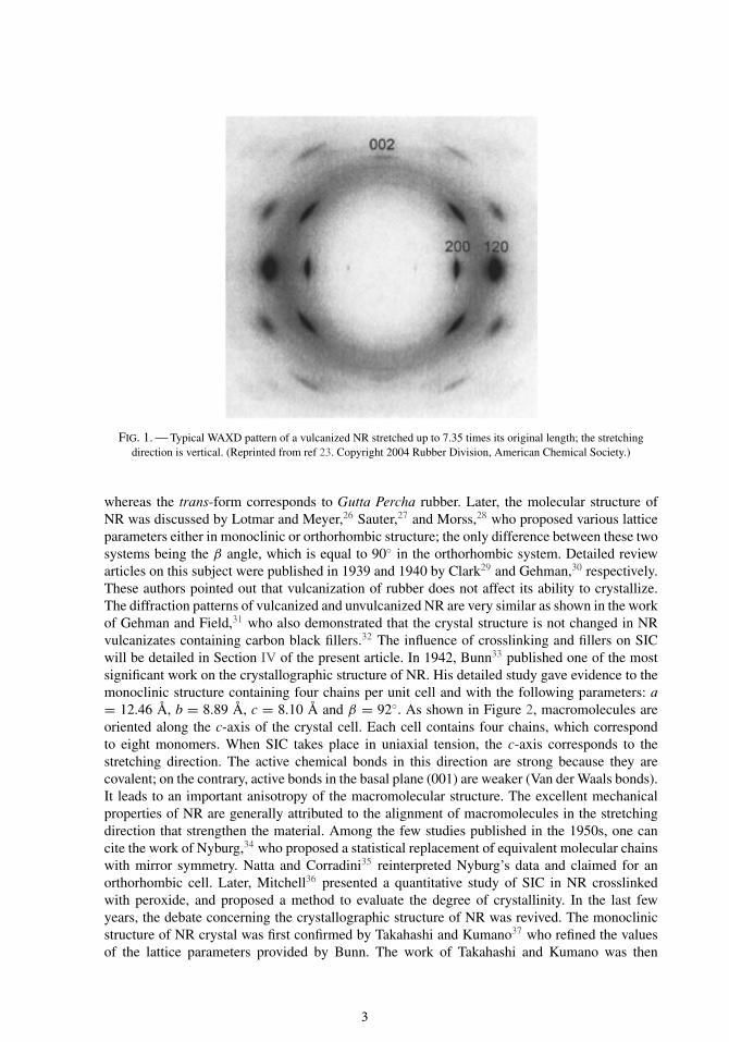
The crystal structure and the lattice parameters of strain-induced crystallized NR can bededuced from the x-ray diffraction pattern. Figure 1 gives a typical example of a diffractionpattern that can be obtained when x-ray beam is perpendicular to the stretched sample.23 Amongthe most intense diffraction spots, one can distinguish the ones that are due to crystallographicplanes (200), (120), and (002). The position of the spots gives the distance dhkl between (hkl)planes, by using the Bragg law
dhkl = nλ
2 sin θ(1)
where n is a strictly positive integer, λ is the wavelength of the x-ray, and θ is the diffractionangle (also called Bragg angle) of the spot due to (hkl) planes.
The structure and the lattice parameters of NR were first reported in 1928 by Mark and vonSusich.24 They proposed an orthorhombic structure with a = 12.3 Å, b = 8.3 Å, and c = 8.1Å. At the same period, Meyer and Mark25 suggested that NR is the cis-form of polyisoprene
2
FIG. 1. — Typical WAXD pattern of a vulcanized NR stretched up to 7.35 times its original length; the stretchingdirection is vertical. (Reprinted from ref 23. Copyright 2004 Rubber Division, American Chemical Society.)
whereas the trans-form corresponds to Gutta Percha rubber. Later, the molecular structure ofNR was discussed by Lotmar and Meyer,26 Sauter,27 and Morss,28 who proposed various latticeparameters either in monoclinic or orthorhombic structure; the only difference between these twosystems being the β angle, which is equal to 90◦ in the orthorhombic system. Detailed reviewarticles on this subject were published in 1939 and 1940 by Clark29 and Gehman,30 respectively.These authors pointed out that vulcanization of rubber does not affect its ability to crystallize.The diffraction patterns of vulcanized and unvulcanized NR are very similar as shown in the workof Gehman and Field,31 who also demonstrated that the crystal structure is not changed in NRvulcanizates containing carbon black fillers.32 The influence of crosslinking and fillers on SICwill be detailed in Section IV of the present article. In 1942, Bunn33 published one of the mostsignificant work on the crystallographic structure of NR. His detailed study gave evidence to themonoclinic structure containing four chains per unit cell and with the following parameters: a= 12.46 Å, b = 8.89 Å, c = 8.10 Å and β = 92◦. As shown in Figure 2, macromolecules areoriented along the c-axis of the crystal cell. Each cell contains four chains, which correspondto eight monomers. When SIC takes place in uniaxial tension, the c-axis corresponds to thestretching direction. The active chemical bonds in this direction are strong because they arecovalent; on the contrary, active bonds in the basal plane (001) are weaker (Van der Waals bonds).It leads to an important anisotropy of the macromolecular structure. The excellent mechanicalproperties of NR are generally attributed to the alignment of macromolecules in the stretchingdirection that strengthen the material. Among the few studies published in the 1950s, one cancite the work of Nyburg,34 who proposed a statistical replacement of equivalent molecular chainswith mirror symmetry. Natta and Corradini35 reinterpreted Nyburg’s data and claimed for anorthorhombic cell. Later, Mitchell36 presented a quantitative study of SIC in NR crosslinkedwith peroxide, and proposed a method to evaluate the degree of crystallinity. In the last fewyears, the debate concerning the crystallographic structure of NR was revived. The monoclinicstructure of NR crystal was first confirmed by Takahashi and Kumano37 who refined the valuesof the lattice parameters provided by Bunn. The work of Takahashi and Kumano was then
3
FIG. 2. — The crystal structure of NR seen along: (a) c-axis, (b) b-axis, and (c) a-axis. (Reprinted with permission fromref 33. Copyright 1942 Royal Society Publishing.)
questioned by Immirzi et al.38 who argued that rejection of orthorhombic cell is not justified.Finally, a recent study by Rajkumar et al.,39 based on a statistical approach called “linked-atom-least-squares,”40 claimed in favor of orthorhombic cell. However, even if the debate aboutNR crystal is not closed, the relationships between stretching and crystallization of NR can beinvestigated.
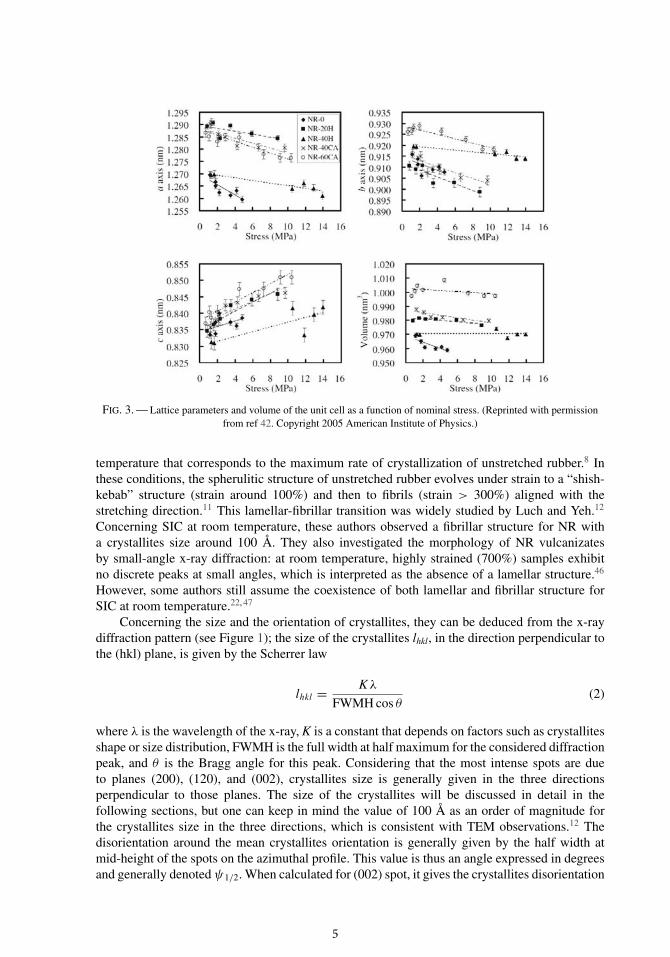
Concerning the evolution of the crystal cell size during a tensile test, Poompradub et al.41, 42
recently studied the evolution of the lattice parameters with loading. Figure 3 shows that lat-tice parameters a and b slightly decrease as the load increases, whereas the lattice parameterc slightly increases. This phenomenon is all the more important that NR is filler free. Never-theless, it should be kept in mind that these variations are very small (about 1% maximum).Considering this, the lattice parameters of the NR crystal cell will not be examined further.The next section will focus on the morphology of NR crystallites and also on their size andorientation, that are more relevant variables to be considered in the studies devoted to SIC ofNR.
B. CRYSTALLITES MORPHOLOGY
Most of the observations concerning the morphology of rubber were performed with trans-mission electron microscope (TEM) on samples cooled around − 25 ◦C11, 43–45 which is the
4
FIG. 3. — Lattice parameters and volume of the unit cell as a function of nominal stress. (Reprinted with permissionfrom ref 42. Copyright 2005 American Institute of Physics.)
temperature that corresponds to the maximum rate of crystallization of unstretched rubber.8 Inthese conditions, the spherulitic structure of unstretched rubber evolves under strain to a “shish-kebab” structure (strain around 100%) and then to fibrils (strain > 300%) aligned with thestretching direction.11 This lamellar-fibrillar transition was widely studied by Luch and Yeh.12
Concerning SIC at room temperature, these authors observed a fibrillar structure for NR witha crystallites size around 100 Å. They also investigated the morphology of NR vulcanizatesby small-angle x-ray diffraction: at room temperature, highly strained (700%) samples exhibitno discrete peaks at small angles, which is interpreted as the absence of a lamellar structure.46
However, some authors still assume the coexistence of both lamellar and fibrillar structure forSIC at room temperature.22, 47
Concerning the size and the orientation of crystallites, they can be deduced from the x-raydiffraction pattern (see Figure 1); the size of the crystallites lhkl, in the direction perpendicular tothe (hkl) plane, is given by the Scherrer law
lhkl = Kλ
FWMH cos θ(2)
where λ is the wavelength of the x-ray, K is a constant that depends on factors such as crystallitesshape or size distribution, FWMH is the full width at half maximum for the considered diffractionpeak, and θ is the Bragg angle for this peak. Considering that the most intense spots are dueto planes (200), (120), and (002), crystallites size is generally given in the three directionsperpendicular to those planes. The size of the crystallites will be discussed in detail in thefollowing sections, but one can keep in mind the value of 100 Å as an order of magnitude forthe crystallites size in the three directions, which is consistent with TEM observations.12 Thedisorientation around the mean crystallites orientation is generally given by the half width atmid-height of the spots on the azimuthal profile. This value is thus an angle expressed in degreesand generally denoted ψ1/2. When calculated for (002) spot, it gives the crystallites disorientation
5
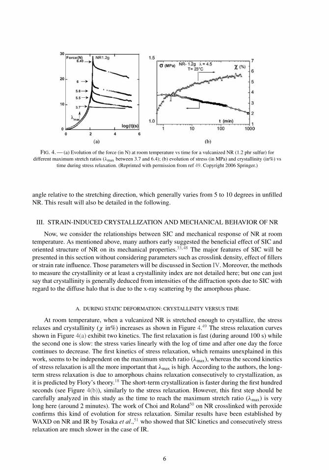
FIG. 4. — (a) Evolution of the force (in N) at room temperature vs time for a vulcanized NR (1.2 phr sulfur) fordifferent maximum stretch ratios (λmax between 3.7 and 6.4); (b) evolution of stress (in MPa) and crystallinity (in%) vs
time during stress relaxation. (Reprinted with permission from ref 49. Copyright 2006 Springer.)
angle relative to the stretching direction, which generally varies from 5 to 10 degrees in unfilledNR. This result will also be detailed in the following.
III. STRAIN-INDUCED CRYSTALLIZATION AND MECHANICAL BEHAVIOR OF NR
Now, we consider the relationships between SIC and mechanical response of NR at roomtemperature. As mentioned above, many authors early suggested the beneficial effect of SIC andoriented structure of NR on its mechanical properties.33, 48 The major features of SIC will bepresented in this section without considering parameters such as crosslink density, effect of fillersor strain rate influence. Those parameters will be discussed in Section IV. Moreover, the methodsto measure the crystallinity or at least a crystallinity index are not detailed here; but one can justsay that crystallinity is generally deduced from intensities of the diffraction spots due to SIC withregard to the diffuse halo that is due to the x-ray scattering by the amorphous phase.
A. DURING STATIC DEFORMATION: CRYSTALLINITY VERSUS TIME
At room temperature, when a vulcanized NR is stretched enough to crystallize, the stressrelaxes and crystallinity (χ in%) increases as shown in Figure 4.49 The stress relaxation curvesshown in Figure 4(a) exhibit two kinetics. The first relaxation is fast (during around 100 s) whilethe second one is slow: the stress varies linearly with the log of time and after one day the forcecontinues to decrease. The first kinetics of stress relaxation, which remains unexplained in thiswork, seems to be independent on the maximum stretch ratio (λmax), whereas the second kineticsof stress relaxation is all the more important that λmax is high. According to the authors, the long-term stress relaxation is due to amorphous chains relaxation consecutively to crystallization, asit is predicted by Flory’s theory.18 The short-term crystallization is faster during the first hundredseconds (see Figure 4(b)), similarly to the stress relaxation. However, this first step should becarefully analyzed in this study as the time to reach the maximum stretch ratio (λmax) is verylong here (around 2 minutes). The work of Choi and Roland50 on NR crosslinked with peroxideconfirms this kind of evolution for stress relaxation. Similar results have been established byWAXD on NR and IR by Tosaka et al.,51 who showed that SIC kinetics and consecutively stressrelaxation are much slower in the case of IR.
6
FIG. 5. — Variation of (120) spot intensity vs time, at room temperature and for three stretch ratios: λ = 3.62 (bottom),λ = 4 (middle), λ = 4.52 (top). (Reprinted from ref 54. Copyright 1967 Rubber Division, American Chemical Society.)
The short-term crystallization for a static stretch is much more difficult to analyze thanlong-term crystallization because λmax is never reached instantaneously; moreover, conventionalx-ray diffraction requires slow data acquisition (typically few minutes) that is not compatiblewith the study of short-time effects. Despite these problems, the early stage of SIC has beeninvestigated by WAXD in the 1930s by Acken et al.52 and Long et al.,53 who tried to answer thefollowing question: “Is SIC instantaneous or not?” Their studies were devoted to the first secondsof SIC and they suggested that this phenomenon requires a “time lag” to be established. In theirfirst study,52 a very ingenious device was designed to measure this time lag; this apparatus wasthe first one that permits to stretch a rubber cyclically during WAXD measurements. As x-raydetectors needed to be exposed for a very long time, samples were rapidly stretched (in 0.5 sec)many times to a fixed stretch and maintained for a certain time (a few seconds). Thanks to astroboscopic technique, the very weak diffracted beam was accumulated along the time. In theirsecond study,53 authors showed that crystallization can be detected after approximately 1 s forλmax = 4.15 (for stretching maintained approximately 5 s). They concluded that the alignmentof macromolecules is not instantaneous. In 1967, Dunning and Pennells54 made the same kindof experiments with another original device and performed a very precise study of SIC kinetics.Figure 5 shows the evolution of crystallinity [measured on the (120) spot] with time and forvarious strain levels. They suggested that a short delay exists before crystallization. The durationof this initial period before crystallization is shown to be very sensitive to the maximum stretchratio: 18 s at λmax = 3.6, 1 s at λmax = 4, 130 ms at λmax = 4.5, and 50 ms at λmax = 5. Moreover,SIC kinetics clearly increases as λmax increases, and crystallinity evolves almost linearly withthe log of time in particular for λ = 4. Nevertheless, for λ > 4, the results suggest two slopesin the crystallinity versus log of time curve, as it was previously observed in Figure 4(b), whichconfirms a faster kinetics for short-term crystallization. One should notice that the result obtainedby these authors at λmax = 5 is in good agreement with the results of Mitchell and Meier55
who investigated SIC by measuring the temperature, according to the method of Votinov et al.56
7
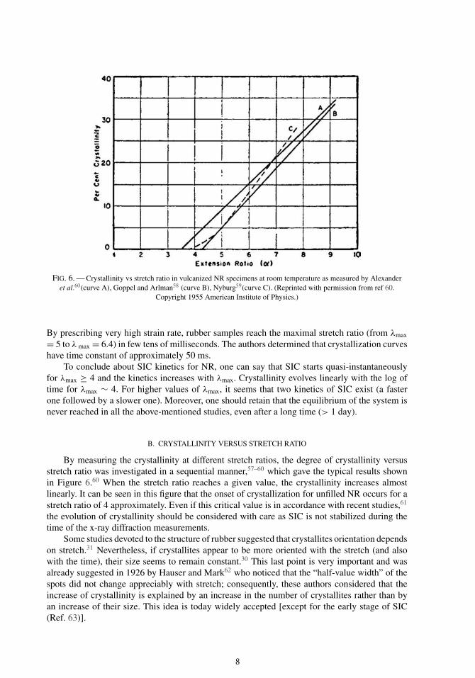
FIG. 6. — Crystallinity vs stretch ratio in vulcanized NR specimens at room temperature as measured by Alexanderet al.60(curve A), Goppel and Arlman58 (curve B), Nyburg59(curve C). (Reprinted with permission from ref 60.
Copyright 1955 American Institute of Physics.)
By prescribing very high strain rate, rubber samples reach the maximal stretch ratio (from λmax
= 5 to λ max = 6.4) in few tens of milliseconds. The authors determined that crystallization curveshave time constant of approximately 50 ms.
To conclude about SIC kinetics for NR, one can say that SIC starts quasi-instantaneouslyfor λmax ≥ 4 and the kinetics increases with λmax. Crystallinity evolves linearly with the log oftime for λmax ∼ 4. For higher values of λmax, it seems that two kinetics of SIC exist (a fasterone followed by a slower one). Moreover, one should retain that the equilibrium of the system isnever reached in all the above-mentioned studies, even after a long time (> 1 day).
B. CRYSTALLINITY VERSUS STRETCH RATIO
By measuring the crystallinity at different stretch ratios, the degree of crystallinity versusstretch ratio was investigated in a sequential manner,57–60 which gave the typical results shownin Figure 6.60 When the stretch ratio reaches a given value, the crystallinity increases almostlinearly. It can be seen in this figure that the onset of crystallization for unfilled NR occurs for astretch ratio of 4 approximately. Even if this critical value is in accordance with recent studies,61
the evolution of crystallinity should be considered with care as SIC is not stabilized during thetime of the x-ray diffraction measurements.
Some studies devoted to the structure of rubber suggested that crystallites orientation dependson stretch.31 Nevertheless, if crystallites appear to be more oriented with the stretch (and alsowith the time), their size seems to remain constant.30 This last point is very important and wasalready suggested in 1926 by Hauser and Mark62 who noticed that the “half-value width” of thespots did not change appreciably with stretch; consequently, these authors considered that theincrease of crystallinity is explained by an increase in the number of crystallites rather than byan increase of their size. This idea is today widely accepted [except for the early stage of SIC(Ref. 63)].
8
FIG. 7. — (a) Stress-strain curve for the first and the third cycle of two vulcanized NR (H: 2 phr sulfur, L: 3 phr sulfur);(b) intensity of (120) spot vs strain. (Reprinted from ref 65. Copyright 1940 American Chemical Society.)
C. DURING A TENSION-RETRACTION TEST WITH A CONVENTIONAL X-RAY SOURCE
The stress-strain curve of NR is known to be hysteretic for a long time (see, for example,Williams and Sturgis64); this hysteresis is generally more important for rubbers that exhibit SIC.
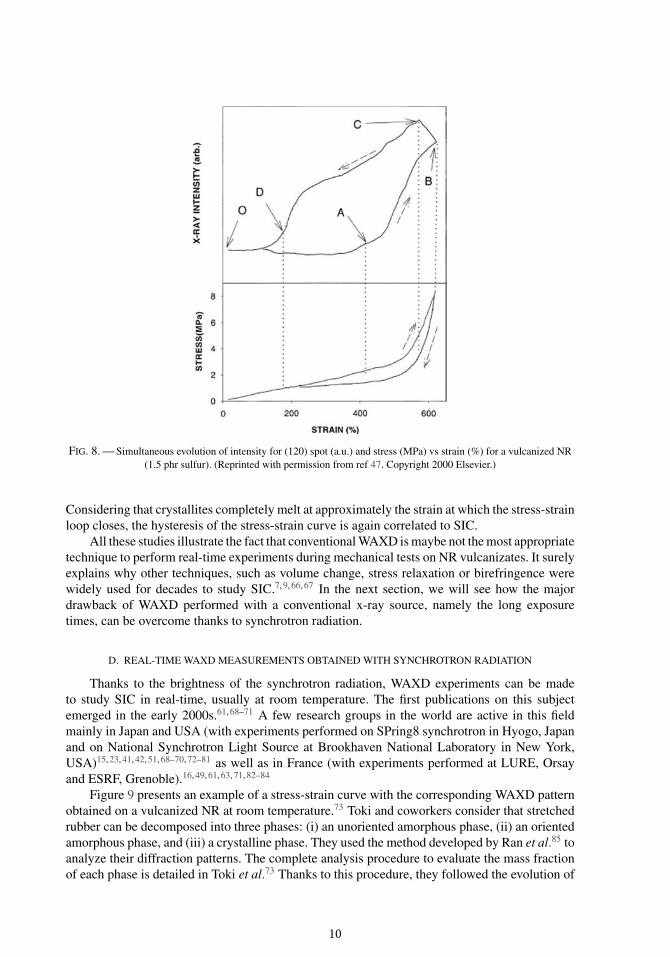
This typical feature was first related to SIC in 1940 by Clark et al.65 as shown in Figure 7.The mechanical tests were performed at a constant displacement speed of 2 inch/min, whereasthe WAXD measurements were made at different constant stretch ratios during one hour. Conse-quently, a precise correlation between the stress-strain curve and the intensity of diffraction-straincurve is not possible. However, the merit of Clark and coworkers is still to have been the firststo suggest experimentally that the mechanical hysteresis of a tension-retraction cycle is closelyrelated to SIC phenomenon. Treloar66 also highlighted the link between these two curves a fewyears later by the means of birefringence. Goppel and Arlman58 investigated more deeply the hys-teresis of SIC by using the same sequential technique (5 min pause for WAXD measurements ateach stretch ratio). They clearly showed that, for the same value of stretch ratio, the crystallinity ishigher in the retraction phase than in the tension one. This kind of sequential measurements havebeen recently performed by Toki et al.47 Even if the detection techniques have been improved for60 years, the exposure time to obtain the whole WAXD pattern remains too long (30 minutes)to clearly follow SIC during a mechanical test. To investigate SIC in real-time, these authorsrecorded the intensity of the brightest equatorial spot, i.e., the (120) spot, during a continuoustension-retraction test. With this method, Toki et al.47 were the first, to the author’s knowledge, toobtain simultaneously the stress-strain curve and the x-ray intensity-strain curve (see Figure 8).
9
FIG. 8. — Simultaneous evolution of intensity for (120) spot (a.u.) and stress (MPa) vs strain (%) for a vulcanized NR(1.5 phr sulfur). (Reprinted with permission from ref 47. Copyright 2000 Elsevier.)
Considering that crystallites completely melt at approximately the strain at which the stress-strainloop closes, the hysteresis of the stress-strain curve is again correlated to SIC.
All these studies illustrate the fact that conventional WAXD is maybe not the most appropriatetechnique to perform real-time experiments during mechanical tests on NR vulcanizates. It surelyexplains why other techniques, such as volume change, stress relaxation or birefringence werewidely used for decades to study SIC.7, 9, 66, 67 In the next section, we will see how the majordrawback of WAXD performed with a conventional x-ray source, namely the long exposuretimes, can be overcome thanks to synchrotron radiation.
D. REAL-TIME WAXD MEASUREMENTS OBTAINED WITH SYNCHROTRON RADIATION
Thanks to the brightness of the synchrotron radiation, WAXD experiments can be madeto study SIC in real-time, usually at room temperature. The first publications on this subjectemerged in the early 2000s.61, 68–71 A few research groups in the world are active in this fieldmainly in Japan and USA (with experiments performed on SPring8 synchrotron in Hyogo, Japanand on National Synchrotron Light Source at Brookhaven National Laboratory in New York,USA)15, 23, 41, 42, 51, 68–70, 72–81 as well as in France (with experiments performed at LURE, Orsayand ESRF, Grenoble).16, 49, 61, 63, 71, 82–84
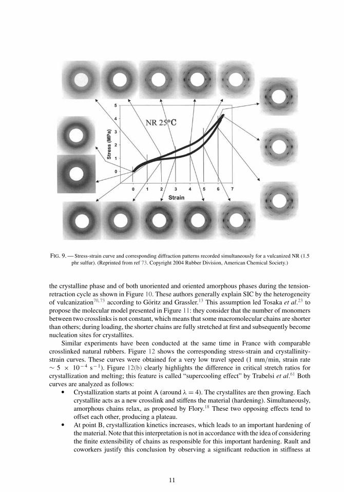
Figure 9 presents an example of a stress-strain curve with the corresponding WAXD patternobtained on a vulcanized NR at room temperature.73 Toki and coworkers consider that stretchedrubber can be decomposed into three phases: (i) an unoriented amorphous phase, (ii) an orientedamorphous phase, and (iii) a crystalline phase. They used the method developed by Ran et al.85 toanalyze their diffraction patterns. The complete analysis procedure to evaluate the mass fractionof each phase is detailed in Toki et al.73 Thanks to this procedure, they followed the evolution of
10
FIG. 9. — Stress-strain curve and corresponding diffraction patterns recorded simultaneously for a vulcanized NR (1.5phr sulfur). (Reprinted from ref 73. Copyright 2004 Rubber Division, American Chemical Society.)
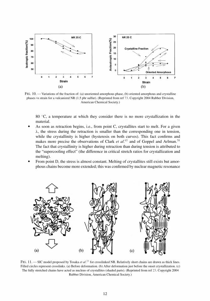
the crystalline phase and of both unoriented and oriented amorphous phases during the tension-retraction cycle as shown in Figure 10. These authors generally explain SIC by the heterogeneityof vulcanization70, 73 according to Goritz and Grassler.13 This assumption led Tosaka et al.23 topropose the molecular model presented in Figure 11: they consider that the number of monomersbetween two crosslinks is not constant, which means that some macromolecular chains are shorterthan others; during loading, the shorter chains are fully stretched at first and subsequently becomenucleation sites for crystallites.
Similar experiments have been conducted at the same time in France with comparablecrosslinked natural rubbers. Figure 12 shows the corresponding stress-strain and crystallinity-strain curves. These curves were obtained for a very low travel speed (1 mm/min, strain rate∼ 5 × 10− 4 s− 1). Figure 12(b) clearly highlights the difference in critical stretch ratios forcrystallization and melting; this feature is called “supercooling effect” by Trabelsi et al.61 Bothcurves are analyzed as follows:
� Crystallization starts at point A (around λ = 4). The crystallites are then growing. Eachcrystallite acts as a new crosslink and stiffens the material (hardening). Simultaneously,amorphous chains relax, as proposed by Flory.18 These two opposing effects tend tooffset each other, producing a plateau.
� At point B, crystallization kinetics increases, which leads to an important hardening ofthe material. Note that this interpretation is not in accordance with the idea of consideringthe finite extensibility of chains as responsible for this important hardening. Rault andcoworkers justify this conclusion by observing a significant reduction in stiffness at
11
FIG. 10. — Variations of the fraction of: (a) unoriented amorphous phase, (b) oriented amorphous and crystallinephases vs strain for a vulcanized NR (1.5 phr sulfur). (Reprinted from ref 73. Copyright 2004 Rubber Division,
American Chemical Society.)
80 ◦C, a temperature at which they consider there is no more crystallization in thematerial.
� As soon as retraction begins, i.e., from point C, crystallites start to melt. For a givenλ, the stress during the retraction is smaller than the corresponding one in tension,while the crystallinity is higher (hysteresis on both curves). This fact confirms andmakes more precise the observations of Clark et al.65 and of Goppel and Arlman.58
The fact that crystallinity is higher during retraction than during tension is attributed tothe “supercooling effect” (the difference in critical stretch ratios for crystallization andmelting).
� From point D, the stress is almost constant. Melting of crystallites still exists but amor-phous chains become more extended; this was confirmed by nuclear magnetic resonance
FIG. 11. — SIC model proposed by Tosaka et al.23 for crosslinked NR. Relatively short chains are drawn as thick lines.Filled circles represent crosslinks. (a) Before deformation. (b) After deformation just before the onset crystallization. (c)The fully stretched chains have acted as nucleus of crystallites (shaded parts). (Reprinted from ref 23. Copyright 2004
Rubber Division, American Chemical Society.)
12
FIG. 12. — Simultaneous evolution of: (a) stress and (b) crystallinity vs stretch ratio, during a tension-retraction cycle(strain rate ∼ 5 × 10 − 4 s− 1) at 22 ◦C for a vulcanized NR (1.2 phr sulfur). (c) Evolution of the mechanical hysteresis
vs the maximum crystallinity measured at the maximum stretch ratio for different samples of two vulcanized NRcontaining: 1.2 phr sulfur (black triangles), 2 phr sulfur (white triangles). (Reprinted from ref 61. Copyright 2003
American Chemical Society.)
(NMR) studies.49 Once again, these two effects offset each other (as between point Aand B). Last crystallites melt at point E.
One of the major conclusions of this work is that the mechanical hysteresis is mainly due toSIC. This point is highlighted in Figure 12(c) that shows the mechanical hysteresis H (in J/cm3)obtained for tests performed at different λmax as a function of the maximum crystallinity χ max
reached for each value of λmax. Considering this relation, these authors considered the contributionof the viscoselastic properties on the mechanical hysteresis as negligible. This research team didnot consider the oriented amorphous phase in their WAXD studies,61, 71, 82 but they investigated
13
FIG. 13. — Evolution of crystallites: (a) size (l002) and (b) disorientation along c-axis at 23 ◦C for a vulcanized NR (1.2phr sulfur) vs stretch ratio. (Reprinted from ref 61. Copyright 2003 American Chemical Society.)
it through NMR studies.16, 49 The latter studies show that a part of the macromolecules becomemore and more aligned during stretching until SIC starts, which makes sense if one considers thatmacromolecules need to be aligned to crystallize. During crystallization the amorphous chainsalignment remains roughly constant.
Among the above-mentioned studies, some of them contain data about the evolution ofcrystallites size and orientation during one mechanical cycle. The size of crystallites was measuredby Trabelsi et al.61 along (002) direction corresponding to the stretching direction or along (200)and (120) directions by Tosaka et al.72 or along those three directions by Chenal et al.63, 84
According to the latter authors, the dimensions of crystallites for a NR containing 1.5 phr sulfurand stretched at λ = 5 at room temperature are approximately: l200 = 100 Å, l120 = 30 Å and l002
= 90 Å.84
As shown in Figure 13, crystallites size in the stretching direction (l002) is rather constantduring the whole cycle.61 This was confirmed by Chenal et al.84 on NR samples having differentnetwork chain density (constant sulfur content, variable CBS content). The evolution of crystallitessize along the two other directions is not so clear. Tosaka et al.72 found that l200 and l120
decrease during stretching whereas Chenal et al. obtained the opposite result: in their study,crystallites seem to grow during stretching till λ = 5. Even if these results are contradictorywith the previous ones, an increase of crystallites volume would not completely explain theincrease of crystallinity. Consequently, from all studies, it can be concluded that the increaseof crystallinity is mainly due to an increase of the number of crystallites, as proposed earlierby Hauser and Mark.62 SIC is thus mainly governed by nucleation rather than by growth ofcrystallites.
As seen in Figure 13(b), crystallites disorientation along the c-axis, i.e., in (002) direction, isaround 5◦ during tension and remains constant. During retraction, there is an additional disorien-tation: crystallites are slightly disoriented before melting.61 Tosaka et al.72 observed exactly thesame trend for the orientation along the (200) direction, which suggests that the crystallites aremore disoriented during the retraction in all directions. This can be easily understood by recallingthat crystallites are less constrained in space during retraction.
Now that we know more about SIC, the influence of other key parameters (depending onexperimental conditions) is reviewed in the next section.
14
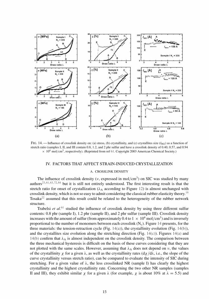
FIG. 14. — Influence of crosslink density on: (a) stress, (b) crystallinity, and (c) crystallites size (l002) as a function ofstretch ratio (samples I, II, and III contain 0.8, 1.2, and 2 phr sulfur and have a crosslink density of 0.40, 0.57, and 0.94
× 104 mol/cm3, respectively). (Reprinted from ref 61. Copyright 2003 American Chemical Society.)
IV. FACTORS THAT AFFECT STRAIN-INDUCED CRYSTALLIZATION
A. CROSSLINK DENSITY
The influence of crosslink density (ν, expressed in mol/cm3) on SIC was studied by manyauthors23, 61, 63, 72, 84 but it is still not entirely understood. The first interesting result is that thestretch ratio for onset of crystallization (λA according to Figure 12) is almost unchanged withcrosslink density, which is not so easy to admit considering the classical rubber elasticity theory.19
Tosaka22 assumed that this result could be related to the heterogeneity of the rubber networkstructure.
Trabelsi et al.61 studied the influence of crosslink density by using three different sulfurcontents: 0.8 phr (sample I), 1.2 phr (sample II), and 2 phr sulfur (sample III). Crosslink densityincreases with the amount of sulfur (from approximately 0.4 to 1 × 10⁴ mol/cm3) and is inverselyproportional to the number of monomers between each crosslink (Nc). Figure 14 presents, for thethree materials: the tension-retraction cycle (Fig. 14(a)), the crystallinity evolution (Fig. 14(b)),and the crystallites size evolution along the stretching direction (Fig. 14(c)). Figures 14(a) and14(b) confirm that λA is almost independent on the crosslink density. The comparison betweenthe three mechanical hysteresis is difficult on the basis of these curves considering that they arenot plotted with the same scales. However, assuming that λA does not depend on ν, the valuesof the crystallinity χ for a given λ, as well as the crystallinity rates (dχ/dλ, i.e., the slope of thecurve crystallinity versus stretch ratio), can be compared to evaluate the intensity of SIC duringstretching. For a given value of λ, the less crosslinked NR (sample I) has clearly the highestcrystallinity and the highest crystallinity rate. Concerning the two other NR samples (samplesII and III), they exhibit similar χ for a given λ (for example, χ is about 10% at λ = 5.5) and
15
FIG. 15. — Influence of crosslinking on the intensity of (200) spot for vulcanized NR samples: crosslink density is2.12, 1.78, 1.46, 1.31, and 1.01 × 10⁴ mol/cm3 for samples NR1, NR2, NR3, NR4, and NR5, respectively. (Reprinted
with permission from ref 15. Copyright 2010 The Society of Polymer Science.)
equivalent crystallinity rates. Nevertheless, the critical stretch ratio for which the last crystals melt(λE) being higher for sample III, the authors concluded that SIC is lowered when crosslink densityincreases. They also noticed that crystallites size in the stretching direction (Fig. 14(c)) decreasesas the crosslink density increases. This reduction in size was confirmed by other studies in whichit was also observed in the other directions.23, 63, 84 This can be explained by considering thatmacromolecular chains are all the more shorten that crosslink density increases. Consequently,their ability to move in order to produce big crystallites is lowered. Trabelsi et al.61 suggest thatcrosslinks play the same role than entanglements and limit both SIC and crystallites size: forlower crosslinked NR, the crystallinity is higher because the longer chains between crosslinkscan form larger crystallites (in the stretching direction), and we can assume that their volumeevolves the same way. For the two other samples, if we consider that crystallites size and volumeare reduced for the most crosslinked sample (sample III), it induces a large number of crystallitessince crystallinity (related to volume fraction of the crystalline phase) is comparable in bothsamples. Consequently, one can reasonably conclude from this study that an increase in crosslinkdensity increases the number of crystallites and reduces their volume.
Concerning the effect of crosslink density on SIC, Tosaka et al.23 first obtained results onvulcanized NR that seem to be contradictory with the ones of Trabelsi and coworkers. Theyplotted the crystallinity versus stretch ratio for five NR vulcanizates, with crosslink densityvarying approximately from 1 to 2 × 10⁴ mol/cm3, and concluded that SIC is all the moreimportant that crosslink density is high. Very recently, they have reconsidered their initial dataand they plotted again crystallinity as a function of stretch ratio as shown in Figure 15.15 NR1 isthe rubber with the highest crosslink density, whereas NR5 is the one with the lowest crosslinkdensity. This curve suggests that both maximum crystallinity and maximum crystallinity rateare larger for the intermediate crosslink density NR3 sample (1.46 × 10⁴ mol/cm3). Moreover,Tosaka et al.72 observed a decrease in crystallites size as the crosslink density increases. Thiswould suggest that maximum crystallinity, i.e., the maximum volume fraction of crystallites, isreached for an optimal combination of number of crystallites and volume of each crystallite.
The existence of an optimal crosslink density for the SIC of vulcanized NR was alreadysuggested by Chenal et al.63, 84 For highly crosslinked NR (from 1.61 to 1.95 × 10⁴ mol/cm3),they clearly established that SIC decreases as the crosslink density increases.84 This result is ingood agreement with the one of Tosaka et al.15 in the same range of crosslink density. Chenal andcoworkers showed that SIC diminution is associated with an important reduction of the crystallites
16
volume: from 290 nm3 for ν = 1.61 × 10⁴ mol/cm3 to 130 nm3 for ν = 1.95 × 10⁴ mol/cm3.They also considered the case of a very low crosslinked NR (0.25 × 10⁴ mol/cm3) that exhibitsa low crystallinity rate. Considering these results, they proposed an optimal crosslink density ofabout 1.2 × 10⁴ mol/cm3.
To close this discussion and by considering all the above-mentioned studies, the authorof the present review proposes the following conclusions for crosslink density greater than 1× 10⁴ mol/cm3:
� nucleation of crystallites is supposed to be governed by the local stretch ratio of themacromolecules, and thus it increases as crosslink density increases,
� the maximum crystallites size is governed by chain length between two crosslinks, andconsequently it decreases as crosslink density increases. Moreover, SIC is assumed todisappear if crosslink density is too high (the crystallites volume would tend towardszero),
� an optimal crosslink density exists for SIC; it corresponds to a relatively high numberof crystallites associated to a large crystallites volume, the product of these two valuesbeing proportional to crystallinity. The existence of an optimal crosslink density ofapproximately 1.5 × 10⁴ mol/cm3 for SIC is proposed. It is coherent with the work ofMorrell and Stern,86 who investigated SIC through volume changes. In their work, thisoptimal crosslink density for SIC corresponds roughly to the optimal tensile strength.
For low crosslinked NR, further investigations are required. Indeed, the results obtainedby Trabelsi et al.,61 who showed that SIC is all the more intense that crosslinking is weak,contradict the proposition made by Chenal et al.,84 who suggested that, below 1.2 × 10⁴ mol/cm3,crystallinity rate decreases as crosslink density decreases. Concerning this last point, one shouldconsider the case of unvulcanized NR in which SIC can occur even if the tensile strength is verylow. For low crosslink density, the role of entanglements that act as crosslinks should be takeninto account and investigated as suggested by Trabelsi et al.61
B. CARBON BLACK FILLERS
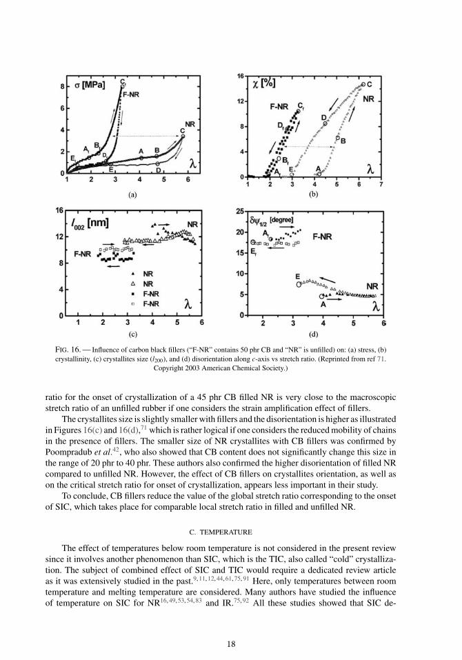
The influence of carbon black (CB) fillers on the mechanical response of NR is well knownfor many years.87–89 As shown in Figure 16(a), the addition of carbon black (50 phr in thatexample) stiffens the material: for a given λ, the stress is higher in filled rubber than in unfilledone.71 The corresponding crystallinity is shown in Figure 16(b). One can see that the onsetof crystallization corresponds to a lower value of stretch ratio: λA ∼ 2 instead of λA ∼ 4 forunfilled rubber. Gehman and Field32 already noticed this offset of λA in CB filled NR. Moreover,the “supercooling effect” is not so important. Based on the former works of Guth and Gold,90
and Mullins and Tobin,88 Trabelsi et al.71 considered that CB fillers lead to an amplification ofstress as they locally increase the stretch of macromolecular chains. These authors extended thisamplification factor concept to other physical properties such as crystallinity, melting temperatureand crystallites size. This amplification effect increases the local strain in the deformable rubbermatrix and makes the nucleation of crystallites easier (λA is lower in CB filled rubber). Howeverthe maximum crystallinity that can be reached in CB filled NR is lower, partly because the volumefraction of matter that can crystallize is reduced.
Poompradub et al.42 studied the stress-strain behavior and the crystallinity evolution for anunfilled NR and two different CB filled NR (one with 20 phr of CB and the other with 40 phr).They also noticed that SIC starts for lower strain values in CB filled NR. By taking into accountthe volume fraction of both CB fillers and occluded rubber (supposed to remain undeformed), theysuggest that the local strain corresponding to onset of crystallization (denoted α0 in their study)is almost the same for the three materials. Chenal et al.63 also determined that the local stretch
17
FIG. 16. — Influence of carbon black fillers (“F-NR” contains 50 phr CB and “NR” is unfilled) on: (a) stress, (b)crystallinity, (c) crystallites size (l200), and (d) disorientation along c-axis vs stretch ratio. (Reprinted from ref 71.
Copyright 2003 American Chemical Society.)
ratio for the onset of crystallization of a 45 phr CB filled NR is very close to the macroscopicstretch ratio of an unfilled rubber if one considers the strain amplification effect of fillers.
The crystallites size is slightly smaller with fillers and the disorientation is higher as illustratedin Figures 16(c) and 16(d),71 which is rather logical if one considers the reduced mobility of chainsin the presence of fillers. The smaller size of NR crystallites with CB fillers was confirmed byPoompradub et al.42, who also showed that CB content does not significantly change this size inthe range of 20 phr to 40 phr. These authors also confirmed the higher disorientation of filled NRcompared to unfilled NR. However, the effect of CB fillers on crystallites orientation, as well ason the critical stretch ratio for onset of crystallization, appears less important in their study.
To conclude, CB fillers reduce the value of the global stretch ratio corresponding to the onsetof SIC, which takes place for comparable local stretch ratio in filled and unfilled NR.
C. TEMPERATURE
The effect of temperatures below room temperature is not considered in the present reviewsince it involves another phenomenon than SIC, which is the TIC, also called “cold” crystalliza-tion. The subject of combined effect of SIC and TIC would require a dedicated review articleas it was extensively studied in the past.9, 11, 12, 44, 61, 75, 91 Here, only temperatures between roomtemperature and melting temperature are considered. Many authors have studied the influenceof temperature on SIC for NR16, 49, 53, 54, 83 and IR.75, 92 All these studies showed that SIC de-
18
FIG. 17. — Influence of temperature on: (a) crystallinity vs stretch ratio (NR with 1.2 phr sulfur) and (b) stress-straincurve (NR with 0.8 phr sulfur). (Reprinted with permission from ref 83. Copyright 2005 Springer.)
creases as temperature increases. This was clearly exhibited by Albouy et al.83 and Rault et al.16,who followed the crystallinity of NR versus stretch ratio for various temperatures. As seen inFigure 17(a), Albouy et al.83 showed a regular decrease of SIC with temperature for an unfilledNR and noticed that SIC is almost inexistent at 80 ◦C. They also showed that temperature affectsthe stretch ratio for the onset of crystallization (λA), which increases with the temperature. Theseauthors also suggested that the influence of temperature on SIC is difficult to take into accountthrough the mechanical response of NR, because temperature has two effects: when it increases,crystallization decreases or even disappears, and on the other way it modifies the behavior of theamorphous phase. Considering this, they tried to evalute the effect of temperature on SIC only,by correcting the mechanical behavior of an unfilled NR. They used the classical stress-strainrelationship given by Treloar,93 which gives the stress σ as a function of temperature
σ = nkT
(λ − 1
λ2
)(3)
(where n is the number of chains per unit volume, k the Boltzmann constant, T the temper-ature and λ the stretch ratio), to extrapolate the stress at 72 ◦C; it gives the dashed line inFigure 17(b). They assumed that the difference between this corrected behavior and the responseat 20 ◦C represents the contribution of SIC. In addition, Rault et al.49 plotted the stress-straincurves of a NR filled with 20 phr of carbon black for four temperatures and measured simul-taneously the crystallinity as a function of stretch ratio (see Figure 18(a), 18(b)). They noticedthat both mechanical and crystallinity hysteresis are reduced when temperature increases. Theseobservations confirm the strong correlation between the mechanical behavior of NR and SIC.For the same maximum stretch ratio, the crystallinity decreases from 8% at 20 ◦C to 1% at 60◦C. For this CB filled rubber, the temperature mainly affects the crystallinity rate (dχ/dλ). Oneshould note that the mechanical tests presented in Figure 18 are performed at a low displacementrate (0.035 mm/s), which corresponds to a strain rate of approximately 10− 3 s− 1. The influenceof strain rate has to be considered with care when the effect of the temperature is evaluated (seenext section).
Miyamoto et al.92 noticed that heating also reduces the crystallinity of unfilled IR during atension-retraction cycle. In particular, these authors reported the stretch ratio values for both onsetof crystallization and completion of melting (λA and λE respectively, according to Figure 17(b)).From 0 to 60 ◦C, they clearly showed an increase of these two values as well as a decrease oftheir difference (the so-called “supercooling effect”).
19
FIG. 18. — Influence of temperature on: (a) stress-strain curve and (b) crystallinity vs stretch ratio for a filledvulcanized NR (20 phr CB, 1.2 phr sulfur). (Reprinted with permission from ref 49. Copyright 2006 Springer.)
Finally, to the author’s knowledge, the effect of temperature in the range of 20–80 ◦C onboth size and orientation of the crystallites has not been investigated.
D. STRAIN RATE
In Section III A, it has been shown that SIC appears very rapidly during stretching. Con-sidering the short time of the delay before crystallization, one can consider that SIC occurs inall the quasi-static tests previously presented, for which strain rate is always smaller than 1 s− 1.Nevertheless, during mechanical tests the system is always out of equilibrium even at very lowstrain rate (10− 5 s− 1), since we have seen that both stress and crystallinity are still evolving aftera long time (1 day) during a static test.
Miyamoto et al.92 have conducted an extensive study on strain rate influence on IR over fourdecades (from 7 × 10− 4 s− 1 to 7 s− 1). They have demonstrated that the onset of crystallizationis shifted from λ = 5 to λ = 6 when the strain rate is multiplied by 104.
The effect of strain rate on SIC was also investigated on NR by Trabelsi94 and Rault et al.49
In Figure 19, the plateau AB appears less distinct for the highest strain rate (5.5 × 10− 4 s− 1
compared to 4 × 10− 5 s− 1).49 Considering their explanation for the stress-strain curve (seeSection III D), these authors assumed that SIC kinetics is larger than chains relaxation kinetics.The latter being very low, the chains cannot relax easily for the higher strain rate, and thus thestress increases. In this very low strain rates regime, λA seems to be the same: strain is assumedto be too slow to delay crystallization. Trabelsi94 investigated higher strain rates for tension-retraction tests (from 1.5 × 10− 3 s− 1 to 5 × 10− 2 s− 1). For these values, the plateau ABcompletely disappears and for a given strain (for example, λ = 5), the stress during stretch islower for the higher strain rate. The crystallinity was followed by WAXD and the results showeda small shifting towards higher values for λA. These measurements confirmed that the resultsobtained by Miyamoto et al.51 for IR are also valid for NR. However, the faster SIC kinetics forNR compared to IR reduces this strain rate effect. Trabelsi94 also measured a lower crystallinityfor the higher strain rate (5 × 10− 2 s− 1) at a given strain, which explains the lower stress shenoticed. In that case, SIC rate would limit the stiffening of rubber. Nevertheless, one must keepin mind that strain rate also influences the mechanical behavior of the amorphous phase.
Finally, considering a quasi-static strain rate in the range of 10− 3 s− 1 as a reference state, itcan be said that:
20
FIG. 19. — Influence of low strain rates on the stress-strain curve of a vulcanized NR (1.2 phr sulfur): V = 1 mm/minand V = 0.07 mm/min corresponding to strain rate of 5.5 × 10− 4 s− 1 and 4 × 10 − 5 s− 1, respectively. (Reprinted
with permission from ref 49. Copyright 2006 Springer.)
� a reduction in strain rate induces a decrease in the hardening effect of SIC just after λA
because polymer chains can relax, which means that chains relaxation rate is smallerthan crystallization rate,
� an increase in strain rate also induces a decrease in the hardening effect of SIC becausecrystallization is delayed; strain rate becomes larger than crystallization rate, whichshifts λA towards higher values.
The high strain rate regime (above 1 s− 1) can be considered through the results of thecyclic experiments of Dunning and Pennells54 presented in Section III A (see also Figure 4).In particular, a critical strain rate at which SIC disappears can be deduced from the duration ofthe initial period before SIC starts. As this period is all the more short that λmax is high, thecritical strain rate naturally increases with λmax: ∼3 s− 1 at λmax = 4, ∼27 s− 1 at λmax = 4.5, and∼80 s− 1 at λmax = 5.
The size and the orientation of crystallites have been investigated by Trabelsi94 (strain ratesin the range of 1.5 × 10− 3 to 5 × 10− 2 s− 1) and it seems that they are almost unchanged bythe strain rate.
E. FATIGUE
The fatigue of rubber has been extensively investigated for decades (see, for example, thereview articles of Mars and Fatemi95, 96). The first investigations in the 1930s and 1940s showedthat NR has remarkable fatigue properties especially in the positive load ratio regime.48, 97 Inparticular, Cadwell et al.100 showed that an increase of λmin, for a given λ, increases fatiguelife. This effect was recently investigated by Andre et al.98 and Saintier et al.99 who highlightedit through a Haigh diagram. This phenomenon was also observed by Lindley:100 fatigue crackgrowth rates strongly decrease when R ratio increases. As all these peculiar properties wereonly observed on rubbers that crystallize under strain, all these works referred to SIC to explainthem. Recently, Mars101 showed that a model based on fatigue crack growth characteristics (thepower-law slope and the fatigue threshold) can take into account SIC effects and reproducethe Haigh diagram and the Cadwell diagram. Considering all these studies, it is important toquantify SIC for fatigue loading conditions, by using WAXD for example. Despite this fact, such
21
experiments are almost inexistent, mainly because the typical frequencies of fatigue tests (1 Hzor more) are not compatible with the long time acquisition required by x-ray diffraction. Oneshould cite again the pioneering works of Acken et al.52 and Long et al.:53 even if their studieswere not devoted to fatigue, they were the firsts to use cyclic loading conditions combined to asynchronized exposition to the x-rays at the maximum strain in order to accumulate the weakintensity of the diffracted beam. With this stroboscopic technique, these authors studied the “timelag” necessary for SIC to start (Section III A). This idea was updated in the 1960s by Kawaiet al.102 who developed an improved version of Acken’s initial device to study semi-crystallinepolymers. They subsequently used it to study SIC of NR.103, 104 To the author’s knowledge, thesestudies are the only published ones concerning SIC evolution measured by WAXD during afatigue test on NR. However, this work is limited to a high R ratio (λmin = 3.5 and λmax = 4.5) forwhich crystallites never melt (λmin is greater than the critical stretch ratio for crystallites fusion).Kawai104 followed the evolution of the diffracted intensities along the equatorial direction, i.e.,through the (200) and (120) spots, for the minimal (λmin = 3.5) and the maximal stretch ratio(λmax = 4.5) during 105 cycles. SIC appears gradually during the cyclic test while the amorphoushalo “degenerates” in the mean time. These changes seem to level off around 103 cycles for themaximum strain and around 105 cycles for the minimum strain. This author also determined thatan increase in frequency (from 0.1 to 10 Hz) reduces the degree of crystallinity.
Trabelsi94 performed some dynamic cyclic tests and showed that SIC can disappear whenthe frequency reaches a too high value. She explained the existence of this critical frequencyby two effects: (i) the temperature rises which decreases SIC, as seen previously; and (ii) thedeformation that takes place faster than crystallization. This critical frequency is between 1 and10 Hz for the experimental conditions she considered. It increases as λmax increases (becauseSIC kinetics is higher) and as λ decreases (because strain rate is lower). For example, when λ
= 4.7 the critical frequency is 1 Hz for λmax = 5.7 (strain rate is about 15 s− 1) and 2 Hz for λmax
= 6.5 (strain rate is about 30 s− 1). These values are a little bit smaller compared to the one thatcan be deduced from the work of Dunning and Pennells:54 ∼10 Hz for λmax = 5 and λ = 4.
Considering the lack of published studies dealing with SIC during fatigue, further investi-gations are needed: (i) to explore the evolution of SIC during fatigue, especially when λmin issmaller than the critical stretch ratio for crystallites fusion; (ii) to consider high λmax values thatcould for example occur at fatigue crack tip. For the latter situation, the critical frequency isexpected to be larger than the above-mentioned values. This could possibly explain that the goodfatigue resistance of NR, particularly for positive R ratio, is not sensitive to frequency in the usualfrequencies range. These investigations should be preferentially carried out on CB filled NR forwhich most of the fatigue studies had been performed.
F. CRACK TIP
As it was already emphasized in the introduction of the present article, NR is known to havea very good resistance to crack growth, either in static or in fatigue loading conditions.2, 3, 96
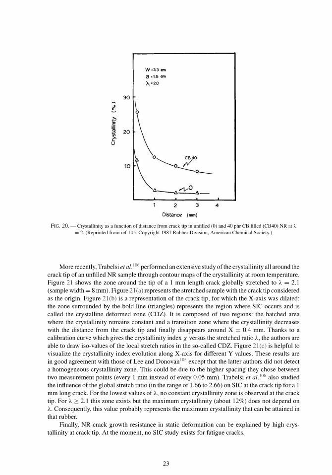
Lee and Donovan105 were among the first researchers to investigate the crystallinity at thecrack tip of a stretched cut sample by the means of WAXD. For an initial cut of 15 mm in a33 mm width sample of NR vulcanizates, they measured the crystallinity at different distancesfrom crack tip along the direction perpendicular to the stretching direction. Figure 20 shows thecrystallinity versus the distance from crack tip for an unfilled and a carbon black filled NR. Asexpected, the crystallinity strongly increases in the vicinity of the crack tip because of high localstretch ratios. The amplification of the crystallinity due to carbon black fillers, which is clearlyseen in Figure 20, is consistent with the one observed in uncut specimens (see Section IV B).
22
FIG. 20. — Crystallinity as a function of distance from crack tip in unfilled (0) and 40 phr CB filled (CB40) NR at λ
= 2. (Reprinted from ref 105. Copyright 1987 Rubber Division, American Chemical Society.)
More recently, Trabelsi et al.106 performed an extensive study of the crystallinity all around thecrack tip of an unfilled NR sample through contour maps of the crystallinity at room temperature.Figure 21 shows the zone around the tip of a 1 mm length crack globally stretched to λ = 2.1(sample width = 8 mm). Figure 21(a) represents the stretched sample with the crack tip consideredas the origin. Figure 21(b) is a representation of the crack tip, for which the X-axis was dilated:the zone surrounded by the bold line (triangles) represents the region where SIC occurs and iscalled the crystalline deformed zone (CDZ). It is composed of two regions: the hatched areawhere the crystallinity remains constant and a transition zone where the crystallinity decreaseswith the distance from the crack tip and finally disappears around X = 0.4 mm. Thanks to acalibration curve which gives the crystallinity index χ versus the stretched ratio λ, the authors areable to draw iso-values of the local stretch ratios in the so-called CDZ. Figure 21(c) is helpful tovisualize the crystallinity index evolution along X-axis for different Y values. These results arein good agreement with those of Lee and Donovan105 except that the latter authors did not detecta homogeneous crystallinity zone. This could be due to the higher spacing they chose betweentwo measurement points (every 1 mm instead of every 0.05 mm). Trabelsi et al.106 also studiedthe influence of the global stretch ratio (in the range of 1.66 to 2.66) on SIC at the crack tip for a 1mm long crack. For the lowest values of λ, no constant crystallinity zone is observed at the cracktip. For λ ≥ 2.1 this zone exists but the maximum crystallinity (about 12%) does not depend onλ. Consequently, this value probably represents the maximum crystallinity that can be attained inthat rubber.
Finally, NR crack growth resistance in static deformation can be explained by high crys-tallinity at crack tip. At the moment, no SIC study exists for fatigue cracks.
23
FIG. 21. — (a) Crack tip region of a stretched (λ = 2.1) vulcanized NR (1.2 phr sulfur); (b) crystallinity map around thecrack tip; (c) crystallinity vs distance from the crack tip at different heights. (Reprinted from ref 106. Copyright 2002
American Chemical Society.)
V. CONCLUSIONS AND PERSPECTIVES
For the last 85 years, many studies were devoted to the study of strain-induced crystallization(SIC) of natural rubber (NR) by the means of WAXD. WAXD measurements provide veryinstructive data to analyze SIC since they give, additionally to the crystallinity, both size andorientation of crystallites.
Part of these investigations was performed to explore the crystalline phase of NR, for examplethe lattice parameters of the crystal cell; but very rapidly, some researchers focused their workon the relationships between the outstanding mechanical properties of NR and SIC. At the endof this article, the following major conclusions can be drawn:
� When NR is stretched to a stretch ratio greater than a threshold value corresponding tothe onset of crystallization (about λ = 4 for unfilled NR, whatever the crosslink density),some of the macromolecules arrange themselves in crystallites presumably composedof fibrillar chains, which are aligned with the stretching direction.
� During static tests, SIC starts almost instantaneously when λ is greater than 4 and cancontinue for days. Crystallization kinetics increases greatly with the maximum stretchratio (λmax). SIC is accompanied by a stress decrease due to the relaxation of amorphouschains.
24
� During a tension-retraction test, SIC can be studied in real-time by using synchrotronradiation. The major result of such studies is that the mechanical hysteresis of unfilledNR is mainly due to SIC, more precisely to the difference between the stretch ratio at theonset of crystallization and the one at crystallites melting. Moreover, the crystallites sizebeing almost constant during the mechanical cycle, the crystallinity raise is associatedwith an increase of the number of crystallites.
Many factors affect the SIC of NR: some of them depend on material composition and theother ones depend on experimental conditions:
� As crosslink density increases, the number of crystallites increases and their size de-creases. It exists an intermediate crosslink density that maximizes the volume fractionof crystallites and thus the crystallinity. Moreover, the stretch ratio corresponding to theonset of crystallization is roughly independent of the crosslink density.
� Carbon black fillers amplify the local stretch of the chains, which makes SIC start at alower macroscopic stretch ratio.
� SIC of NR decreases when the temperature increases and it disappears at “high” tem-peratures (above 80 ◦C for unfilled NR).
� NR is not very sensitive to strain rate compared to other crystallizable rubbers such asIR, because the early stages of SIC are fast. However, the hardening effect of SIC isdiminished at very low strain rates (lower than 10− 3 s− 1) because the slow kinetics ofchains relaxation counterbalances it by decreasing the stress; at high strain rates (from 1s− 1 to 100 s− 1, depending on λmax) SIC disappears because its kinetics is slower thanstrain rate.
� In fatigue, the influence of raising frequencies that can lower SIC has to be consideredby the increase of both temperature and strain rate. The critical frequency at which SICdisappears increases with λmax (higher SIC kinetics) and as λ decreases (lower strainrate).
� Finally, crack growth resistance of NR is correlated with a high crystallinity at the cracktip, due to high strain level.
Some perspectives for WAXD investigations of SIC are suggested, mainly for filled NR:� Fatigue cracks should be studied and correlated to fatigue crack growth rates, probably
by using synchrotron radiation to follow SIC along fatigue life.� Multiaxial loading conditions should also be considered to take into account the complex
strain field that exists in industrial parts.For such conditions, the mechanisms of SIC will be probably different from those described
in the present review: the high strain level reached at the crack tip could increase the criticalfrequency at which SIC disappears, and the multiaxial loading will surely modify the crystallitesformation and their orientation.
These future experimental investigations are all the more important that current modelingand simulation works are dedicated to constitutive models and end-of-life criteria for industrialparts submitted to complex multiaxial and/or fatigue loadings.
VI. ACKNOWLEDGMENTS
The author would like to thank E. Verron, S. Beurrot, and W.V. Mars for fruitful discussionson the subject.
VII. REFERENCES
1G. J. Lake and A. G. Thomas, “Engineering with Rubber – How to Design Rubber Components,” Chapter 5, A. N.
Gent, Ed., Carl Hanser Verlag, Munich, 2001.
25
2G. J. Lake, RUBBER CHEM. TECHNOL. 68, 435 (1995).3G. R. Hamed, H. J. Kim, and A. N. Gent, RUBBER CHEM. TECHNOL. 69, 807 (1996).4Y. Tanaka and L. Tarachiwin, RUBBER CHEM. TECHNOL. 82, 283 (2009).5Y. Tanaka, RUBBER CHEM. TECHNOL. 74, 355 (2001).6J. R. Katz, Naturwiss. 13, 410 (1925).7N. Bekkedahl and L. A. Wood, Ind. Eng. Chem. 33, 381 (1941).8L. A. Wood and N. Bekkedahl, J. Appl. Phys. 17, 362 (1946).9A. N. Gent, Trans. Faraday Soc. 50, 521 (1954).10J.-B. Le Cam, RUBBER CHEM. TECHNOL. 83, 247 (2010).11E. H. Andrews, Pure Appl. Chem. 31, 91 (1972).12D. Luch and G. S. Y. Yeh, J. Appl. Phys. 43, 4326 (1972).13D. Goritz and R. Grassler, RUBBER CHEM. TECHNOL. 60, 217 (1987).14L. R. G. Treloar, Trans. Faraday Soc. 37, 84 (1941).15M. Tosaka, S. Kohjiya, Y. Ikeda, S. Toki, and B. S. Hsiao, Polym. J. 42, 474 (2010).16J. Rault, J. Marchal, P. Judeinstein, and P. A. Albouy, Macromolecules 39, 8356 (2006).17A. M. Healey, P. J. Hendra, and Y. D. West, Polymer 37, 4009 (1996).18P. J. Flory, “Principles of Polymer Chemistry,” Cornell University Press, Ithaca, 1953.19L. R. G. Treloar, “The Physics of Rubber Elasticity,” Oxford University Press, Oxford, 1975.20D. E. Roberts and L. Mandelkern, J. Am. Chem. Soc. 77, 781 (1955).21J. H. Magill, RUBBER CHEM. TECHNOL. 68, 507 (1995).22M. Tosaka, Polym. J. 39, 1207 (2007).23M. Tosaka, S. Kohjiya, S. Murakami, S. Poompradub, Y. Ikeda, S. Toki, I. Sics, and B. S. Hsiao, RUBBER CHEM.
TECHNOL. 77, 711 (2004).24H. Mark and G. von Susich, Kolloid-Z. 46, 11 (1928).25K. H. Meyer and H. Mark, Ber. Dtsch. Chem. Ges. 61, 1939 (1928).26W. Lotmar and K. H. Meyer, Monatsh. Chem. 69, 115 (1936).27E. Sauter, Z. Phys. Chem. B-Chem. Elem. Aufbau. Mater. 36, 405 (1937).28H. A. Morss, J. Am. Chem. Soc. 60, 237 (1938).29G. L. Clark, Ind. Eng. Chem. 31, 1397 (1939).30S. D. Gehman, Chem. Rev. 26, 203 (1940).31S. D. Gehman and J. E. Field, J. Appl. Phys. 10, 564 (1939).32S. D. Gehman and J. E. Field, Ind. Eng. Chem. 32, 1401 (1940).33C. W. Bunn, Proc. R. Soc. London, Ser. A 180, 40 (1942).34S. C. Nyburg, Acta Crystallogr. 7, 385 (1954).35G. Natta and P. Corradini, Angew. Chem. 68, 615 (1956).36G. R. Mitchell, Polymer 25, 1562 (1984).37Y. Takahashi and T. Kumano, Macromolecules 37, 4860 (2004).38A. Immirzi, C. Tedesco, G. Monaco, and A. E. Tonelli, Macromolecules 38, 1223 (2005).39G. Rajkumar, J. M. Squire, and S. Arnott, Macromolecules 39, 7004 (2006).40S. Arnott and A. J. Wonacott, Polymer 7, 157 (1966).41S. Poompradub, M. Tosaka, S. Kohjiya, Y. Ikeda, S. Toki, I. Sics, and B. S. Hsiao, Chem. Lett. 33, 220 (2004).42S. Poompradub, M. Tosaka, S. Kohjiya, Y. Ikeda, S. Toki, I. Sics, and B. S. Hsiao, J. Appl. Phys. 97, 103529
(2005).43E. H. Andrews, Proc. R. Soc. London, Ser. A 270, 232 (1962).44E. H. Andrews, Proc. R. Soc. London, Ser. A 277, 562 (1964).
26
45T. Shimizu, M. Tosaka, M. Tsuji, and S. Kohjiya, RUBBER CHEM. TECHNOL. 73, 926 (2000).46D. Luch and G. S. Y. Yeh, J. Macromol. Sci., Part B: Phys. B 7, 121 (1973).47S. Toki, T. Fujimaki, and M. Okuyama, Polymer 41, 5423 (2000).48W. F. Busse, Ind. Eng. Chem. 26, 1194 (1934).49J. Rault, J. Marchal, P. Judeinstein, and P. A. Albouy, Eur. Phys. J. E: Soft Matter Biol. Phys. 21, 243 (2006).50I. S. Choi and C. M. Roland, RUBBER CHEM. TECHNOL. 70, 202 (1997).51M. Tosaka, D. Kawakami, K. Senoo, S. Kohjiya, Y. Ikeda, S. Toki, and B. S. Hsiao, Macromolecules 39, 5100 (2006).52M. F. Acken, W. E. Singer, and W. P. Davey, Ind. Eng. Chem. 24, 54 (1932).53J. D. Long, W. E. Singer, and W. P. Davey, Ind. Eng. Chem. 26, 543 (1934).54D. J. Dunning and P. J. Pennells, RUBBER CHEM. TECHNOL. 40, 1381 (1967).55J. C. Mitchell and D. J. Meier, J. Polym. Sci., Part A-2: Polym. Phys. 6, 1689 (1968).56M. P. Votinov, S. A. Subbotin, V. V. Samoletova, S. P. Konytovskaya, and E. V. Kuvshinskii, RUBBER CHEM.
TECHNOL. 33, 988 (1960).57J. E. Field, J. Appl. Phys. 12, 23 (1941).58J. M. Goppel and J. J. Arlman, Appl. Sci. Res., Sect. A 1, 462 (1949).59S. C. Nyburg, Br. J. Appl. Phys. 5, 321 (1954).60L. E. Alexander, S. Ohlberg, and G. R. Taylor, J. Appl. Phys. 26, 1068 (1955).61S. Trabelsi, P. A. Albouy, and J. Rault, Macromolecules 36, 7624 (2003).62E. A. Hauser and H. Mark, Kolloidchem. Beih. 22, 63 (1926).63J. M. Chenal, C. Gauthier, L. Chazeau, L. Guy, and Y. Bomal, Polymer 48, 6893 (2007).64I. Williams and B. M. Sturgis, Ind. Eng. Chem. 31, 1303 (1939).65G. L. Clark, M. Kabler, E. Blaker, and J. M. Ball, Ind. Eng. Chem. 32, 1474 (1940).66L. R. G. Treloar, Trans. Faraday Soc. 43, 284 (1947).67P. A. Thiessen and W. Wittstadt, RUBBER CHEM. TECHNOL. 12, 736 (1939).68S. Murakami, K. Senoo, S. Toki, and S. Kohjiya, Polymer 43, 2117 (2002).69S. Toki, I. Sics, S. F. Ran, L. Z. Liu, B. S. Hsiao, S. Murakami, K. Senoo, and S. Kohjiya, Macromolecules 35, 6578
(2002).70S. Toki, I. Sics, S. F. Ran, L. Z. Liu, and B. S. Hsiao, Polymer 44, 6003 (2003).71S. Trabelsi, P. A. Albouy, and J. Rault, Macromolecules 36, 9093 (2003).72M. Tosaka, S. Murakami, S. Poompradub, S. Kohjiya, Y. Ikeda, S. Toki, I. Sics, and B. S. Hsiao, Macromolecules 37,
3299 (2004).73S. Toki, I. Sics, S. F. Ran, L. Z. Liu, B. S. Hsiao, S. Murakami, M. Tosaka, S. Kohjiya, S. Poompradub, Y. Ikeda, and
A. H. Tsou, RUBBER CHEM. TECHNOL. 77, 317 (2004).74S. Toki, I. Sics, B. S. Hsiao, S. Murakami, M. Tosaka, S. Poompradub, S. Kohjiya, and Y. Ikeda, J. Polym. Sci., Part
B: Polym. Phys. 42, 956 (2004).75S. Toki, I. Sics, B. S. Hsiao, M. Tosaka, S. Poompradub, Y. Ikeda, and S. Kohjiya, Macromolecules 38, 7064 (2005).76S. Toki, B. S. Hsiao, S. Kohjiya, M. Tosaka, A. H. Tsou, and S. Datta, RUBBER CHEM. TECHNOL. 79, 460 (2006).77S. Toki, I. Sics, C. Burger, D. F. Fang, L. Z. Liu, B. S. Hsiao, S. Datta, and A. H. Tsou, Macromolecules 39, 3588
(2006).78S. Kohjiya, M. Tosaka, F. Masahiro, Y. Ikeda, S. Toki, and B. S. Hsiao, Polymer 48, 3801 (2007).79S. Toki, N. Minouchi, I. Sics, B. S. Hsiao, and S. Kohjiya, Kautsch. Gummi Kunstst. 61, 85 (2008).80S. Amnuaypornsri, J. Sakdapipanich, S. Toki, B. S. Hsiao, N. Ichikawa, and Y. Tanaka, RUBBER CHEM. TECHNOL. 81,
753 (2008).81S. Toki, C. Burger, B. S. Hsiao, S. Amnuaypornsri, J. Sakdapipanich, and Y. Tanaka, J. Polym. Sci., Part B: Polym.
Phys. 46, 2456 (2008).
27
82S. Trabelsi, P. A. Albouy, and J. Rault, RUBBER CHEM. TECHNOL. 77, 303 (2004).83P. A. Albouy, J. Marchal, and J. Rault, Eur. Phys. J. E: Soft Matter Biol. Phys. 17, 247 (2005).84J. M. Chenal, L. Chazeau, L. Guy, Y. Bomal, and C. Gauthier, Polymer 48, 1042 (2007).85S. Ran, D. Fang, X. Zong, B. S. Hsiao, B. Chu, and P. M. Cunniff, Polymer 42, 1601 (2001).86S. H. Morrell and J. Stern, RUBBER CHEM. TECHNOL. 26, 17 (1953).87E. Guth, J. Appl. Phys. 16, 20 (1945).88L. Mullins and N. R. Tobin, J. Appl. Polym. Sci. 9, 2993 (1965).89J. A. C. Harwood and A. R. Payne, J. Appl. Polym. Sci. 10, 315 (1966).90E. Guth and O. Gold, Phys. Rev. 53, 322 (1938).91G. S. Y. Yeh, Polym. Eng. Sci. 16, 145 (1976).92Y. Miyamoto, H. Yamao, and K. Sekimoto, Macromolecules 36, 6462 (2003).93L. R. G. Treloar, Trans. Faraday Soc. 39, 36 (1943).94S. Trabelsi, “Etude statique et dynamique de la cristallisation des elastomeres sous tension,” PhD Thesis (in French),
Paris XI University, Orsay, 2002.95W. V. Mars and A. Fatemi, Int. J. Fatigue 24, 949 (2002).96W. V. Mars and A. Fatemi, RUBBER CHEM. TECHNOL. 77, 391 (2004).97S. Cadwell, R. Merrill, C. Sloman, and F. Yost, Ind. Eng. Chem. 12, 19 (1940).98N. Andre, G. Cailletaud, and R. Piques, Kautsch. Gummi Kunstst. 52, 120 (1999).99N. Saintier, G. Cailletaud, and R. Piques, Int. J. Fatigue 28, 530 (2006).100P. B. Lindley, Int. J. Fract. 9, 449 (1973).101W. V. Mars, RUBBER CHEM. TECHNOL. 82, 51 (2009).102H. Kawai, D. A. Keedy, R. S. Stein, and T. Itoh, J. Polym. Sci., Part B: Polym. Lett. 2, 1075 (1964).103H. Hiratsuka, M. Hashiyama, S. Tomita, and H. Kawai, J. Macromol. Sci., Part B: Phys. 8, 101 (1973).104H. Kawai, Rheol. Acta 14, 27 (1975).105D. J. Lee and J. A. Donovan, RUBBER CHEM. TECHNOL. 60, 910 (1987).106S. Trabelsi, P. A. Albouy, and J. Rault, Macromolecules 35, 10054 (2002).