17 STRATIFICATION AND MIXING OF FLUIDS OF DIFFERENT DENSITIES By S. J. LEACH, Ph.D.* SYNOPSIS In an earlier publication the equations of motion and turbulent diffusion of a buoyant boundary layer were solved by introducing an eddy diffusivity dependent on the Richardson number. Experimental results obtained with methane roof layers (in air) and brine floor layers (in water) showed good agreement with theory. The present paper outlines this work and goes on to discuss the conditions under which the effects of buoyancy are significant and how these effects can be overcome. Consideration is given to limiting the flammable volume produced by the mixing of a layer of flammable gas with air. When the characteristics of the main flow cannot be arranged to give adequate mixing it is possible to in- crease the mixing rate by the use of baffles and by recirculation: the practical application of these methods is discussed. Introduction In many situations it is necessary to rapidly mix two fluids of different densities. For example, if a flammable gas such as methane is being emitted into a stream of air there will be an ignition risk wherever the concentration of the methane lies between 5 and 15%. If the mixing rate is low an appreciable volume of mixture within this range may be present in the flow. The mixing rate may be low if, for instance, a light fluid is emitted at the roof, or a heavy fluid at the floor, of a ventilated tunnel or pipe. This is the situation with methane roof-layers in mines where a source of methane (which is lighter than air) at the roof may form a flammable layer hundreds of feet long. Another field where good mixing is important is in the taking of samples of mixtures flowing in pipes; if mixing is complete a single sample can be used to determine the concentrations of the components of the mixture and, if the input rate of one of the components is known, a measurement of its concentration can give the flow-rate of the main fluid. This paper reviews the work carried out at the Safety in Mines Research Establishment on the turbulent diffusion of stratified fluids, with emphasis on the practical application of this work to pipe flows. The paper first of all discusses a fundamental parameter relevant to mixing in stratified fluids, the Richardson number, and then briefly outlines the basis of the theoretical calculations, stressing the assumptions that were made to obtain an analytic solution. This is followed by a detailed description of the behaviour of layers as predicted by the theory and a discussion of the application of the results to mixing problems. Finally, two methods for increasing mixing are discussed which may have an application to situations where satisfactory mixing cannot be achieved by increasing the speed of the main flow of fluid. The Richardson Number Buoyancy forces are present whenever two fluids of different density are being mixed; these forces can con- siderably influence both the motion and mixing of the two fluids. Thus, when buoyancy forces are large compared with inertia forces, mixing by turbulent diffusion may cease even * Safety in Mines Research Establishment, Ministry of Power, Sheffield. though the flows are turbulent; and where there is a layer of fluid in an inclined tunnel the tendency for the layer fluid to flow in the direction of the buoyancy force may be sufficient to cause it to move, or " back ", against the main flow. Let us consider, for example, a light fluid flowing above a heavy fluid. If the work required to lower the light fluid is greater than that which can be done by the kinetic energy of the turbulence, turbulent mixing may cease. The ratio of the work done against gravity to the work done by the turbulent stresses was first introduced as a governing parameter in this type of situation by Richardson 1, 2 and the expression for this ratio called the Richardson number, Ri, is: where g is gravitational acceleration, and p/ y and u/ y are the gradients of density and velocity in the vertical direc- tion respectively. As the Richardson number tends to zero buoyancy effects will have negligible influence on the rate of turbulent mixing; as the Richardson number tends to a critical value, of about one, turbulent mixing will cease. A characteristic expression for the Richardson number in terms of the bulk properties of the flow (see Fig. 1) can be written as: where p δ is the main-flow density, u δ the main-flow velocity, V is the volumetric rate of input of fluid of density ρ i into the layer, D is the width of the pipe (rectangular cross-section), u is the mean velocity of the layer, δ is the layer thickness, and a is the inclination to the horizontal. Governing Equations The mean velocity of the layer will be influenced by the rate of mixing (i.e. the rate of growth of layer thickness with distance along the layer) and the rate of mixing will be influenced by the mean velocity of the layer. We therefore have to start from the equations governing the motion and mixing of the layer and make some simplifying assumptions to arrive at their solution. The procedure followed by I.Chem.E. SYMPOSIUM SERIES No. 25 (1968: Instn chem. Engrs, London) c
Transcript
17
STRATIFICATION AND MIXING OF FLUIDS OF DIFFERENT DENSITIES
By S. J. LEACH, Ph.D.*
SYNOPSIS
In an earlier publication the equations of motion and turbulent diffusion of a buoyant boundary layer were solved by introducing an eddy diffusivity dependent on the Richardson number. Experimental results obtained with methane roof layers (in air) and brine floor layers (in water) showed good agreement with theory. The present paper outlines this work and goes on to discuss the conditions under which the effects of buoyancy are significant and how these effects can be overcome. Consideration is given to limiting the flammable volume produced by the mixing of a layer of flammable gas with air.
When the characteristics of the main flow cannot be arranged to give adequate mixing it is possible to increase the mixing rate by the use of baffles and by recirculation: the practical application of these methods is discussed.
Introduction
In many situations it is necessary to rapidly mix two fluids of different densities. For example, if a flammable gas such as methane is being emitted into a stream of air there will be an ignition risk wherever the concentration of the methane lies between 5 and 15%. If the mixing rate is low an appreciable volume of mixture within this range may be present in the flow. The mixing rate may be low if, for instance, a light fluid is emitted at the roof, or a heavy fluid at the floor, of a ventilated tunnel or pipe. This is the situation with methane roof-layers in mines where a source of methane (which is lighter than air) at the roof may form a flammable layer hundreds of feet long. Another field where good mixing is important is in the taking of samples of mixtures flowing in pipes; if mixing is complete a single sample can be used to determine the concentrations of the components of the mixture and, if the input rate of one of the components is known, a measurement of its concentration can give the flow-rate of the main fluid.
This paper reviews the work carried out at the Safety in Mines Research Establishment on the turbulent diffusion of stratified fluids, with emphasis on the practical application of this work to pipe flows. The paper first of all discusses a fundamental parameter relevant to mixing in stratified fluids, the Richardson number, and then briefly outlines the basis of the theoretical calculations, stressing the assumptions that were made to obtain an analytic solution. This is followed by a detailed description of the behaviour of layers as predicted by the theory and a discussion of the application of the results to mixing problems. Finally, two methods for increasing mixing are discussed which may have an application to situations where satisfactory mixing cannot be achieved by increasing the speed of the main flow of fluid.
The Richardson Number
Buoyancy forces are present whenever two fluids of different density are being mixed; these forces can considerably influence both the motion and mixing of the two fluids. Thus, when buoyancy forces are large compared with inertia forces, mixing by turbulent diffusion may cease even
* Safety in Mines Research Establishment, Ministry of Power, Sheffield.
though the flows are turbulent; and where there is a layer of fluid in an inclined tunnel the tendency for the layer fluid to flow in the direction of the buoyancy force may be sufficient to cause it to move, or " back ", against the main flow. Let us consider, for example, a light fluid flowing above a heavy fluid. If the work required to lower the light fluid is greater than that which can be done by the kinetic energy of the turbulence, turbulent mixing may cease. The ratio of the work done against gravity to the work done by the turbulent stresses was first introduced as a governing parameter in this type of situation by Richardson1, 2 and the expression for this ratio called the Richardson number, Ri, is:
where g is gravitational acceleration, and p/ y and u/ y are the gradients of density and velocity in the vertical direction respectively. As the Richardson number tends to zero buoyancy effects will have negligible influence on the rate of turbulent mixing; as the Richardson number tends to a critical value, of about one, turbulent mixing will cease.
A characteristic expression for the Richardson number in terms of the bulk properties of the flow (see Fig. 1) can be written as:
where pδ is the main-flow density, uδ the main-flow velocity, V is the volumetric rate of input of fluid of density ρi into the layer, D is the width of the pipe (rectangular cross-section), u is the mean velocity of the layer, δ is the layer thickness, and a is the inclination to the horizontal.
Governing Equations
The mean velocity of the layer will be influenced by the rate of mixing (i.e. the rate of growth of layer thickness with distance along the layer) and the rate of mixing will be influenced by the mean velocity of the layer. We therefore have to start from the equations governing the motion and mixing of the layer and make some simplifying assumptions to arrive at their solution. The procedure followed by
I.Chem.E. SYMPOSIUM SERIES No. 25 (1968: Instn chem. Engrs, London) c
18 LEACH. STRATIFICATION AND MIXING OF FLUIDS OF DIFFERENT DENSITIES
Bakke is outlined below and further details can be obtained from the work of Bakke and Leach.3
The following boundary-layer forms of the equations were used:
Continuity:
Momentum:
where the first term on the right-hand side represents the pressure gradient in the main flow, the second term is the shear-stress gradient normal to the wall, and the final term the component of weight parallel to the roof and a is the inclination to the horizontal.
Diffusion:
where e is the eddy diffusivity and c is the mass concentration of the layer-forming fluid which is connected to the density by the equation:
As we are considering a single source of light fluid only, the mass flux of light fluid remains constant, i.e:
Main Assumptions
To formulate and solve these equations analytically a number of simplifying assumptions (discussed in Bakke and Leach,3) have first to be made. The most important assumptions are:
(a) Variations of inertial terms due to variations in density can be neglected (but variations in weight due to density difference are included).
(b) Mean velocities defined by terms in the integral form of the equations are the same, e.g:
Similarly, different definitions of the mean value of concentration are taken to give the same values.
(c) The eddy diffusivity, e, is the same as that for a turbulent boundary layer unaffected by buoyancy but modified by a function K which depends on the Richardson number only. The eddy viscosity in such a layer is e„ = 0-4 uzy, where «t is the skin friction velocity V(fo/p),
the constant 0-4 is von Karman's constant, and T0 is theshear stress at the wall.
To obtain a mean value of e, the mean value of v over thelayer thickness 8 was used, i.e. y = \8, and a skin-friction coefficient cw for the layer, defined by T0 = cwpil2, wasintroduced. Thus:
Ellison and Turner4 investigated the entrainment of brineinto a turbulent flow of fresh water and obtained a relation between an entrainment coefficient, E, and the Richardson number. For Ri = 0 the value of E was found to be about 0-07 and for Ri = 0-8 the value of E was effectively zero. K(RI) was assumed to be proportional to the relationship obtained by Ellison and Turner for E (Ri), with /c(0) = 1 and /c(0-8) = 0.
We need to introduce a skin-friction coefficient for the main flow, cf, defined by r0
i = cf ps us2, where TO1 is the wall
friction of the main flow. In a pipe flow cs will be constant along the pipe; and since cw will decrease only slowly along the layer as the layer thickness increases, it is assumed constant also. With constant values of cw and cf it follows from the momentum equation that u is constant along the layer.
Equations (4) and (5) when multiplied by (y-S) and integrated from 0 to d give:
The Layering Number
It is possible to use equations (9) and (10) to obtain the mean velocity of the layer and the rate of mixing of the layer (dd/dx) in terms of the independent variables. The independent variables are the slope of the pipe, the friction coefficients and u6l^/[(g Ap V)l(pD)]. This last variable has been called the layering number in previous publications. The introduction of the layering number makes the description of layering simpler, as for the same slope and friction coefficient the velocity and rate of mixing of layers will be the same for a given value of the layering number even if the main-flow velocity, relative density difference, flow-rate into the layer, and width of the layer are different from one flow situation to another.
The width of the layer is equal to the width of the tunnel for rectangular tunnels. For circular cross-section pipes the layer width changes with mixing. However, this is not very important when evaluating the layering number and it has been found that it is sufficiently accurate for many practical applications to put the layer width equal to three-quarters of the pipe diameter.
Layers in a Horizontal Pipe
Fig. 2 shows the dependence of the buoyancy coefficient, K = (l-34V'c>v)-1(d<5/dx) on the layering number for a horizontal pipe. Mixing starts at a slightly lower value of the layering number with the rougher wall. All other parameters
I.Chem.E. SYMPOSIUM SERIES No. 25 (1968: Instn chem. Engrs, London)
LEACH. STRATIFICATION AND MIXING OF FLUIDS OF DIFFERENT DENSITIES 19
th
I
being constant, mixing increases with increase in velocity until eventually the rate of mixing approaches the value for non-buoyant layers, i.e. K = 1 and dJ/dx = l-34\/cw.
A point of particular interest is the value of the layering number at which mixing stops. The relation between (jRQcrit* the layering number and the friction coefficients for the onset of mixing can be obtained from equation (9) by putting d<5/d* = 0
The dependence of:
on cw/cf is practically negligible when cw/cf exceeds three, which would be the case in many practical flows. (.Ri)\{iXusl •$/[(gApV)/(pD)] has a minimum value of 1-9. Consequently, with an assumed critical value of Ri equal to 0-8, the layering number must in any case exceed two before mixing will take place. With values of cwjcf less than about three the critical layering number for mixing to start increases markedly with decreasing cw/cf.
The Layer Length
For any given strength of source the layer can be made as short as desired by increasing the velocity sufficiently, but a layer will always exist unless the velocity is infinitely large. Let us consider the response of the layer length to changes in the layering number. Layer length is defined as the length of roof over which the mean concentration is above, say, the lower flammable limit. Let us assume that the thickness of the layer after the initial mixing near to the source has finished is equal to ^o-* By continuity:
* We have found it satisfactory for practical applications to assume hat the initial mixing as the layer accelerates near to the source alves the input concentration.
where c0 and c are the mean concentrations across the layer at the section where the initial mixing has finished and at a distance x from this section, respectively.
As dc)/dx is constant along the layer (equation (10):
By combining these equations:
For a horizontal pipe a further simplification can be madeif we assume that u = 0-8us (this assumption cannot be made for all situations in inclined pipes as we shall see later) and that u6 = Um, the mean velocity in the pipe. Hence:
Equation (15) can be used to give the mean concentration in the layer or the distance from the source to a given mean concentration. The length of roof over which a flammable concentration is present has an obvious practical importance. Let us now consider, say, the roof concentration, cr (for a layer of light fluid above a heavy one). Experiments by Leach and Barbero5 showed that the roof concentration was about three times the mean concentration for a wide range of skin-friction coefficients and layering numbers. Hence we can write:
3c0 ^ , , 0-8UinDco dd — - ' + — dJ* • • 06)
for a horizontal pipe. To use these equations in a practical application the layer
ing number is first evaluated from the known variables and then used to determine the value of the buoyancy coefficient appropriate to the skin-friction coefficients, and pipe inclination. An example is given in Fig. 2, for a horizontal pipe. Lambert6 tabulates the buoyancy coefficients and mean layer velocities for a wide range of skin-friction coefficients and pipe inclinations. From the buoyancy coefficient the rate of mixing can be calculated (equation (10). The layer length or its concentration at any distance can be calculated by means of equation (14) for inclined pipes or by equations (15) and (16) for horizontal pipes.
Layering Number to Control Effects of Buoyancy in a Horizontal Pipe
Where one gas is mixing with another of different density there will always be a region near to the source of the input gas where high, concentrations are present. It is therefore necessary to establish a criterion for the greatest practicable reduction of the extent of the layer that can be achieved by adjusting the mainstream velocity alone. In this section two possible ways of approaching a criterion are discussed. Firstly, the response of the layer length to changes in the mainstream velocity is discussed and the velocity at which small increases or decreases have little effect on the layer length is determined. Secondly, the possibility is discussed of specifying the mainstream velocity to limit to a given value the total volume of gas present in the layer which can take part in combustion.
In a horizontal pipe turbulent mixing does not take place for layering numbers less than about two. As the layering number is increased above two the response of d<5/dx (the rate of mixing) to a small change in velocity is great at first but becomes less as the layering number increases. We
.Chem.E. SYMPOSIUM SERIES No. 25 (1968: Instn chem. Engrs, London)
20 LEACH. STRATIFICATION AND MIXING OF FLUIDS OF DIFFERENT DENSITIES
suggest that five is a suitable value for the layering number in horizontal pipes. This value gives the velocity at which a small increase or decrease has a small effect on the length of the layer. The criterion can be applied to layers in inclined pipes with uphill ventilation but this, of course, leads to values of the layering number greater than five since turbulent mixing does not start until the layering number is greater than two, as we shall see later.
Equation (16) has been used to evaluate the variation of layer length with ventilation velocity for two methane emission rates, 51/s and 25 1/s (10 and 50ft3/min), in a tunnel 3 m (10 ft) wide; the results are given in Fig. 3. Also marked in Fig. 3 are the values of the ventilation velocity corresponding to a layering number of five with each emission rate. It can be seen that these correspond to ventilation velocities at which small changes have little effect on the layer lengths and large increases are needed to reduce the layer lengths significantly. However, although this criterion expresses what reasonably can be achieved by ventilation in bringing the effects of buoyancy under control, the resulting layer may still not be acceptable, particularly at larger emission rates where a considerable volume of flammable gas may be present.
Let us assume that the layering number is high enough for buoyancy to have little effect, since in this condition our layer is " under control", i.e. small changes in conditions will not affect the situation greatly, as would be the case at lower layering numbers. In these conditions it is possible to derive a simple formula for the volume of flammable gas that is present, as follows:
For high layering numbers:
If we assume that the concentration is uniform over any section through the layer perpendicular to the walls, the flammable volume, Qf, is given by:
From equations (12), (13), (17), (18), and (19):
When buoyancy effects have been overcome the flammable volume is therefore proportional to the square of the methane emission rate and the inverse square of the ventilation velocity. Since we are in a situation where buoyancy is under control it is possible to use the relationship w=c=0-8£/m, and equation (20) can be written in terms of the fully mixed concentration, cL, which is obtained well downstream from the source, and which is equal to V/U,„D2 for a square cross-section pipe:
Thus the flammable volume is proportional to cL2.
Let us consider the example of the methane roof layers shown in Fig. 3, and assume that we wish to limit the total volume occupied by methane above the lower flammable limit to 30 litres (1 ft3). If we assume that mixing near to the source makes the initial concentration, c0, equal to 50% we can use equation (21) to work out the appropriate ventilation velocity. For the emission rate of 25 1/s (50 ft3/min) this gives 2-2 m/s (430 ft/min). For the emission rate of 51/s (10ft3/min) this gives 0-95 m/s (190 ft/min). Thus the velocity of 0-95 m/s derived in section (8) to bring the layer under " buoyancy control" also limits the volume of flammable gas to 30 litres when the emission rate is 5 1/s; but the larger emission rate of 25 1/s requires an increase of velocity from 1-6 to 2-2 m/s to give the same volume of flammable gas. More accurate calculations of the volume of flammable gas in layers have been made by Fletcher who used several assumed concentration profiles.7
Layers in Inclined Pipes
The following discussion will be in terms of a light fluid flowing above a heavy one.
Slope has two important effects on layers. If the ventilation is downhill and too slow the layer will flow uphill against the ventilation. If the ventilation is uphill, at relatively low ventilation velocities the mixing of the layer with the ventilating flow becomes less when the velocity is increased, up to a certain value of the layering number, when the mixing improves for further increases of velocity. This phenomenon was reported by Bakke and Leach8 and Leach and Barbero.3
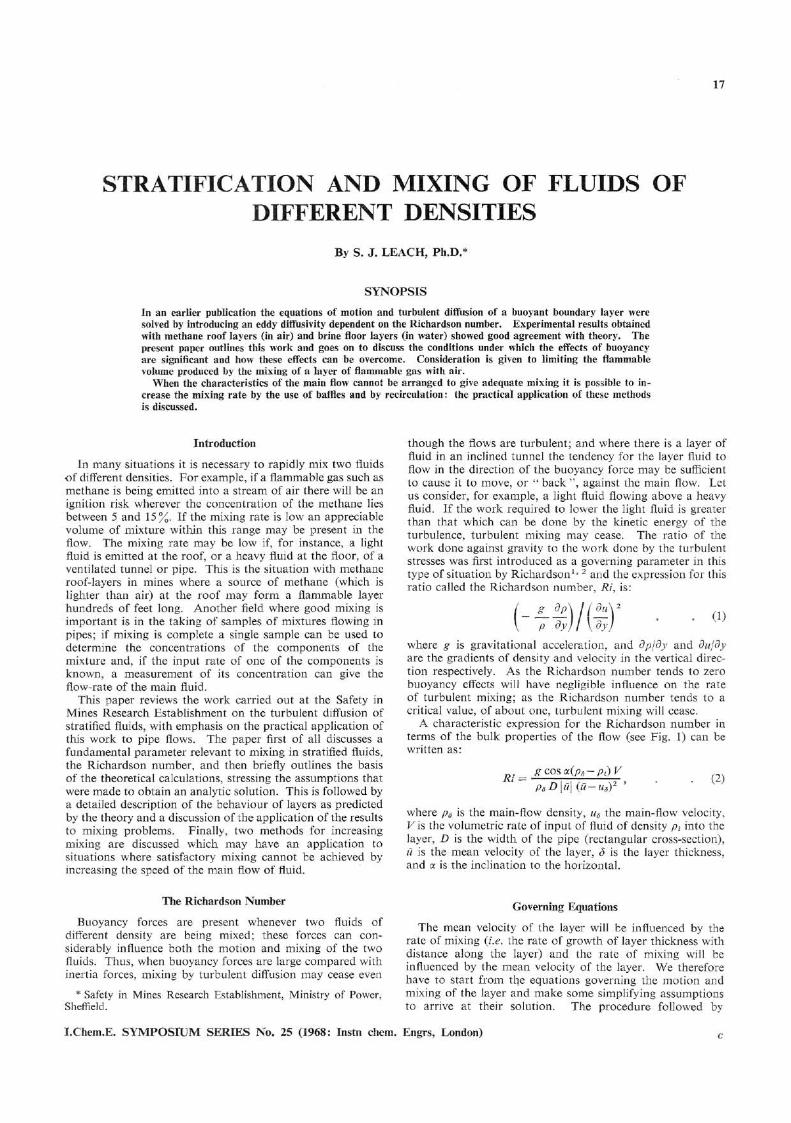
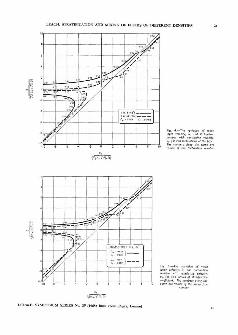
The mean velocity, w, of the layer and the Richardson number of layers in inclined pipes is shown in Figs 4 and 5.
Layers in Uphill Ventilation Flow
Fig. 4 gives results for two inclinations, 1 in 50 and 1 in 1 for cf = 0-0015 and cw = 0004. Fig. 5 gives results at an inclination of 1 in 2 for cf = 0-0015 and cw = 0004 and 002. In Figs 4 and 5, u is divided by ^/[(gApV)/pD)] thus making the velocity dimensionless. Positive layering numbers and velocities correspond to uphill ventilation and flow respectively; similarly, negative layering numbers and velocities
I.Chem.E. SYMPOSIUM SERIES No. 25 (1968: Instn chem. Engrs, London)
LEACH. STRATIFICATION AND MIXING OF FLUIDS OF DIFFERENT DENSITIES 21
I.Chem
.E. SYMPOSIUM SERIES No. 25 (1968: Instn chem. Engrs, London)
22 LEACH. STRATIFICATION AND MIXING OF FLUIDS OF DIFFERENT DENSITIES
correspond to downhill ventilation and flow. Consider first the curve for an inclination of 1 in 50 in Fig. 4. When the layering number is zero we have a free-streaming layer moving uphill at a velocity, in dimensionless form, of 1-1. This value is equal to the velocity obtained from the Ellison and Turner theory4 of free-streaming layers but this is fortuitous since different assumptions are used in the two theories. Essentially, on physical grounds, the present theory applies only when the layer can be considered as a buoyant boundary layer in a turbulent ventilation flow: for a full description of free-streaming layers the reader should therefore consult Ellison and Turner's paper. An increase in layering number from zero to low values increases the layer velocity. The values of the Richardson number are indicated in Fig. 4 along the curve itself; the Richardson number increases with increasing layering number, i.e. the turbulent mixing becomes less as the ventilating velocity is increased. The expression for Richardson's number (equation (2) shows that Ri increases rapidly as u approaches u6. The two velocities become equal when the layering number is about two. At this point the Richardson number has become infinitely large. However, turbulent mixing has ceased before that. The value of the layering number for which turbulent mixing first subsides (and also re-starts) depends on the critical value of Ri, which has been assumed to be 0-8. However, a deviation from the assumed critical value of Ri would not affect the value of the layering number at which Ri = <x> because then there is no mixing and one of the forces determining the layer velocity, viz. the rate of change of momentum due to mixing with the ventilating flow, does not exist. When the ventilation velocity is increased such that it exceeds the layer velocity the Richardson number decreases with increasing ventilation velocity. Broadly speaking, when the layering number is greater than the value at which the layer velocity is equal to the ventilation velocity, the behaviour of the layer is similar to a horizontal layer.
The second curve for uphill ventilation in Fig. 4 shows the behaviour of layers in a pipe of inclination 1 in 1. Qualitatively, the behaviour is similar to what occurs at an inclination 1 in 50; quantitatively there is a marked effect of slope owing to the greater buoyancy forces along the roof. The effect of the greater layer velocity on the Richardson number is more marked, the Richardson number is smaller and the rate of turbulent mixing greater. This result is to be expected, since if the " roof" were vertical no work against gravity would be required in order to mix the layer and consequently the rate of mixing would not be impaired by buoyancy. The value of the layering number at which the layer velocity is equal to the ventilation velocity is greater for the steeper roof.
When the layering number is greater than the value at which the layer velocity is equal to the ventilation velocity then, for the range of layering numbers shown, the Richardson number is larger at the steeper slope. Although the layering numbers in this region are sufficient to overcome the worst effects of buoyancy, the greater buoyancy force along the roof at the steeper slope causes the difference between ventilation velocity and layer velocity to be less; the Richardson number is therefore larger, and the mixing is less. This effect of slope on mixing at large layering numbers is opposite to the behaviour at small layering numbers, when the mixing is better the larger the slope.
The effect of slope on mixing decreases gradually as the layering number increases. Ultimately, buoyancy becomes unimportant and the rate of mixing will approach the constant maximum rate of mixing which equals, on the basis of the present theory, \-34-\/cw whatever the slope. The really important effect of slope in uphill ventilation is that the larger the slope, the larger is the ventilation velocity required to ensure that the mixing will become better if the ventilation is
increased. Fig. 5 shows the effect of varying the friction coefficient for the layer, cw. The velocity of the free-streaming layer at an inclination of 1 in 2 is reduced from 2 to 1 -6 by anincrease in cw from 0004 to 0-02; at the same time, the layering number at which Ri = co falls from 5-5 to 2-7.
Layers in a Downhill Ventilation Flow
Consider first the results for an inclination of 1 in 50. With downhill flow, when the value of the layering number is less than about |2-7| there is just one positive theoretical value for the layer velocity for each value of the layering number. Thus the roof layer will be moving uphill, in the opposite direction to the downhill ventilation flow: it will be "backing " against the ventilation. When the downhill ventilation flow is faster than that corresponding to a layering number of |2-8| there are three possible solutions. The first solution corresponds to the layer moving slowly in the opposite direction to the ventilation. The second solution corresponds to the layer moving slowly in the same direction as the ventilation, but in such a manner that the speed of the layer decreases if the ventilation speed is increased. The third solution corresponds to the layer moving in the same direction as the ventilation, at a velocity comparable to the ventilation velocity. Intuition suggests that only the last solution corresponds to reality.
From the Richardson numbers along the curve, when the ventilation is increased beyond the velocity necessary to make the layer move in the same direction as the ventilation the rate of mixing will improve steadily except for values close to the critical value for reversal, when there is at first a slight increase in the Richardson numbers. In general, though, when the ventilation is downhill and fast enough to make the roof layer move downhill also, the mixing will improve steadily with increasing velocity, and the mixing is turbulent all the time.
A comparison of the Richardson numbers in downhill and uphill ventilation shows that for a given slope and layering number the mixing is always better when the ventilation is downhill although the difference is small at large values of the layering number, when buoyancy has little effect in any case. At intermediate values of the layering number, the reason for the better mixing in downhill ventilation is that the buoyancy force in the uphill direction causes the difference between the layer velocity and the ventilation velocity to be greater.
The effect of roughening the roof is very small and is such that the layering number necessary to make a layer move downhill with the ventilation is slightly less with the rough than with the smooth roof. This result may not be obvious at first sight since the roughness will increase the drag on the layer and it might therefore appear to be more difficult to make the roof layer move downhill in the same direction as as the ventilation. The point is, however, that the important part of the mechanism by which the layer is made to move downhill is the addition of downhill momentum by mixing with the ventilation flow. The rough roof causes the layer to move more slowly in the downhill direction for a given ventilation velocity so that the difference between the layer velocity and the ventilation velocity becomes greater. By itself, this increases the effect on the layer of downhill momentum from the ventilation. In addition, the Richardson number will be smaller and the increased mixing further increases the addition of downhill momentum from the ventilation. The net result is that a smaller ventilation velocity is required to make the roof layer move downhill in spite of the increased wall-drag in the uphill direction.
I.Chem.E. SYMPOSIUM SERIES No. 25 (1968: Instn chem. Engrs, London)
LEACH. STRATIFICATION AND MIXING OF FLUIDS OF DIFFERENT DENSITIES 23
I
Buoyancy Control Layering Numbers for Inclined Pipes
For uphill flow in inclined pipes, it is possible to determine the conditions at which a small increase or decrease in main-flow velocity has little effect on the length of a layer, in the same way as was done for horizontal pipes. This, of course, leads to values of the layering number greater than five since turbulent mixing does not start until the layering number is greater than two, the recommended values of the layering number are given in Fig. 6 for tunnel inclinations up to 1 in 1. Also shown in Fig. 6 are the suggested values of the layering number for preventing layers from flowing uphill against downhill ventilation; these are approximately 10% greater than the theoretical values, since experiments by Bakke and Leach3 indicate that this is necessary. These values can also be regarded as buoyancy control values since it is buoyancy which causes the layer to flow uphill against the ventilation; and at the recommended value the rate of mixing is high.
Volume of Flammable Gas—Inclined Pipes
Providing that the conditions are such that the buoyancy control layering numbers are exceeded, the arguments relating to the layering numbers to control effects of buoyancy in a horizontal pipe apply also to inclined pipes and hence equation (21) can be used to calculate the volume of gas present or to specify a velocity to limit the volume to a pre-determined value.
Mixing by Baffles
In some situations it will not be possible to achieve the buoyancy-control conditions by increasing the main-flow velocity. In such a case mixing can be increased by using a single baffle. One particular type of baffle has been investigated, a plate at right angles to the flow blocking either the lower part of the cross-section of the pipe in order to disperse light roof layers or the upper part in order to disperse dense floor layers.
Let us assume that the same form of parameter governs the mixing action of baffles as governs the mixing of layers, except that we now base the layering number on the mean velocity in the gap over the baffle, Uh.
Fig. 7 shows the variation with baffle layering number and fully mixed concentration of the ratio of the roof concentra-
tion 4-3 diameters from a baffle to the roof concentration immediately above the baffle. The experiments were carried out at three scales:
(1). Large scale with methane roof layers in a 2-4 m x 2-4 m (8 x 8 ft) arched section tunnel (Leach and Barbero).
(2). Mid-scale with carbon dioxide floor layers in a 0-9 m x 0-3 m (3 x 1 ft) tunnel.
(3). Small scale with brine floor layers in a 15-2 cm x 10-2 cm (6 x 4 in.) tunnel.
The experiments were made with h/D (where h is the height of the baffle) between 0-5 and 0-85 and with cf = 00075 (smooth) and cf = 0-022 (very rough).
Fig. 7 suggests that the most important variable is the baffle layering number. An increase in fully mixed concentration, CL, corresponding to an increase in the emission rate into the layer, causes the measured concentration to rise, but by a relatively small amount. The other variables (cf, xw, h/D) do not appear to produce changes outside the error of measurement. From Fig. 7 we can conclude that a baffle layering number in the region of five is the optimum, since further increase has little effect, but a decrease soon leads to a region where the effect of the baffle is small. Similar experiments made at other inclinations (up to 1 in 3£) with brine floor layers showed large effects of inclination at low baffle layering numbers, but little difference from Fig. 7 for layering numbers greater than four. The general conclusion is that the optimum size of baffle for mixing layers in horizontal and uphill ventilated pipes is such that it gives a baffle layering number of five. To minimise the volume of layer-forming fluid present, the baffle should be placed about one tunnel or pipe diameter upstream of the source of the layer.
.Chem.E. SYMPOSIUM SERIES No. 25 (1968: Instn chem. Engrs, London)
24 LEACH. STRATIFICATION AND MIXING OF FLUIDS OF DIFFERENT DENSITIES
Baffles to Prevent Layers Backing
A baffle can be used to prevent backing against the main stream if the baffle height is such as to give a baffle layering number in accordance with the layering numbers in Fig. 6 for downhill ventilation (Leach and Barbero).9 Once again the optimum baffle position is a pipe diameter upstream from the source of layer-forming fluid.
Pressure Loss due to Baffles
Measurements have been made (Leach and Barbero),9
of the pressure loss due to baffles in smooth and in very rough walled tunnels; the results are given in Fig. 8.
Recirculation
Where a baffle cannot be used, because of the increased flow resistance, it is possible to use an extra fan or pump to recirculate part of the flow as illustrated in Fig. 9. This uses additional power but has the advantage over an increase in the main-flow velocity in that the increased flow only occurs in the region where mixing is required and not in the whole system. This is particularly important in coal mines where the cost of ventilation is a few per cent of the cost of the coal mined and doubling, for example, the main-flow velocity would multiply the ventilating costs eight times.
The application of recirculation to practical mining situations is discussed in detail by Bakke, Leach, and Slack1 ° and Leach, Slack, and Thompson11 who concluded that the only problem in using recirculation to increase mixing arises from the influence of pressure changes produced by the recirculation. For example, with the system shown in Fig. 9b there will be a pressure change in the region of the outlet
of the recirculating pipe, Ap, given by:
where Ap is the area of the pipe, A is the area of the tunnel or main pipe, and u„ is the mean outlet velocity from the pipeThis will act in opposition to the original flow and in a small number of practical situations may lead to a reduction in the original main flow rate. Methods of eliminating this pressure change are discussed by Leach, Slack, and Thompson.12
Acknowledgments
I wish to thankjMr. P. Bakke for much helpful advice, Mr. A. Slack for assistance with most of the experimental work, and Mr. H. Thompson and Mr. L. Barbero for assisting withsome parts of it.
LEACH. STRATIFICATION AND MIXING OF FLUIDS OF DIFFERENT DENSITIES 25
The above quantities may be expressed in any set of consistent units in which force and mass are not defined independently.
References 1 Richardson, L. F. Proc. R. Soc, 1920, A97, 354. 2 Richardson, L. F. Phil. Mag., 1925, 49, 81. 3 Bakke, P. and Leach, S. J. Appl. sclent. Res., 1965, A15, 97. 4 Ellison, T. H. and Turner, J. S. / . Fluid Mech., 1959, 6, 423. 5 Leach, S. J. and Barbero, L. P. Res. Rep. Saf. Mines Res.
Bd, 222/1964. 6 Lambert, N. K. To be published. 7 Fletcher, B. To be published. 8 Bakke, P. and Leach, S. J. Res. Rep. Saf. Mines Res. Bd,
195/1960. 9 Leach, S. J. and Barbero, L. P. Res. Rep. Saf. Mines Res. Bd,
217/1963. 10 Bakke, P., Leach, S. J., and Slack, A. Colliery Engng, 1964,
41,471. 11 Leach, S. J., Slack, A., and Thompson, H. Res. Rep. Saf.
Mines Res. Bd, 242/1966.
The manuscript of this paper was received on 1 April, 1967.
DISCUSSION
Mr. J. R. CROWTHER said that the baffle had been placed upstream of the material coming into the pipe on the lower face: why could it not go on the top face after the stream ?
Dr. LEACH said that the question was interesting because if the baffle were placed on the upper surface as envisaged by Mr.
Crowther, there would be better mixing downstream. However, in an application, one was not always clear where the source was. Supposing the source was further upstream than baffle, there would be, upstream of the baffle and close to it, a region which was not mixing, which could contain a large volume of flammable gas, and the hazard would therefore be increased. The mechanism of the mixing downstream from the baffle in this case was quite different from that considered in the paper because mixing would be due to eddies behind the baffle. In the case considered in the paper, the mixing occurred as the flow expanded and where there was boundary layer separation.
Mr. B. Y. WALKER said that as he understood the paper, which he found very interesting, two systems were being dealt with which were mutually soluble or miscible in the end. There was a number of reactions in the chemical industry, the manufacture of DDT being one, where there were two immiscible layers which have to be adequately mixed.
Did the author's theory apply in these cases ?
Dr. LEACH said that the theory would not apply. Surface tension would become important and some of the calculations would not work.
Dr. B. SHAW asked if the baffle was not inconvenient in design.
Dr. LEACH replied that it was inconvenient from several points of view. It was in the way of operations going on and it also introduced a pressure loss into the system which decreased the total throughput. One reason for the investigation was that it had been the traditional method for centuries to use baffles in this way. It was not always the most effective way. Instances had come to light in the mining industry where a methane layer had been discovered and a single baffle had been erected. It had not been effective and another and then another had been put in finishing with twelve baffles obstructing the flow and not satisfactorily mixing the layers. What the present work had shown was that a single baffle could be used effectively provided that it was made in accordance with the recommendations given in the paper.
Dr. J. H. BURGOYNE said he thought the treatment was two-dimensional. He asked Leach to say a few words about the three-dimensional situation where there was freedom of the escaping gas to spread laterally.
Dr. LEACH said that he would not want to say much about the third dimension because the situation where there was freedom to spread laterally had not been under investigation. One aspect concerned what happened with a circular pipe— what was the value of the width of the pipe to be introduced into the layering number? This did not present great difficulties because the width appeared inside a cube root in the layering number, so if one was in error in the diameter, it did not affect the result greatly. Experience showed that three-quarters of the maximum width of the pipe could be used to evaluate the layering number
I.Chem.E. SYMPOSIUM SERIES No. 25 (1968: Instn chem. Engrs, London)