The use of long span prestressed beams in bridge construction is very common. Even if the sections are economical the erection of the beam still poses a challenge in construction. Not much work has been done in the analysis of stress and deflection at erection stage. This paper deals with the behavior of precast prestressed beams during lifting. Since the spans of these beams are large, it may fail due to cracking during erection. In this paper a detailed 3-dimensional Finite Element Analysis of 2 prestressed beam sections was done with incorporating the effect of initial imperfections and prestress. Results were obtained for both prestressed beam and non-prestressed beam and were compared with Moen’s formulae. To include the effect of prestressing cables in the beam new additional formulae were introduced and used in combination with the Moen’s. The results obtained were approximately validated with the Finite Element Analysis results. It is seen that the prestressing cables have a significant effect on the behavior of a beam during lifting. For a prestressed beam the overhang length should be kept minimum for safe erection which is opposite in the case of a normal beam.
8
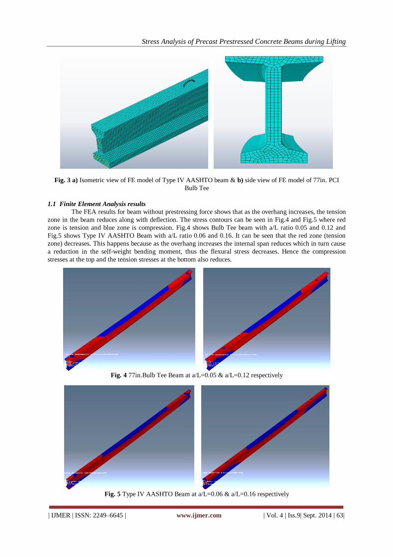
International OPEN ACCESS Journal Of Modern Engineering Research (IJMER) | IJMER | ISSN: 2249–6645 | www.ijmer.com | Vol. 4 | Iss.9| Sept. 2014 | 61| Stress Analysis of Precast Prestressed Concrete Beams during Lifting V. M. Gaykar 1 , J. G. Solanki 2 1 M.tech Student, Structural Engineering Department, Veermata Jijabai Technological Institute, India 2 Asst. Professor, Structural Engineering Department, Veermata Jijabai Technological Institute, India I. INTRODUCTION The use of precast prestressed beams is wide in bridge construction. These beams are long with imperfections and tend to deflect about both major and minor axis during lifting. Moreover the prestressing cable causes the beam to get highly stressed which in turn results in cracking. Thus for safe erection, it is necessary to study the deflection and stress behavior of the prestressed beam. Many numerical formulae are available in previous literature for analyzing lateral behavior of the beam at lifting.[1]–[7] Also it is found that the camber due to prestress has a considerable effect on the deflection of the beam. [5], [8]. The previous literature also contains an experimental study on initial imperfection.[9] In this paper, two beam sections viz. 77in. PCI Bulb Tee and Type IV AASHTO beam [9] are numerically modeled using Abaqus software to study its behavior. This study compares the finite element analysis results with the analytical solutions from previous literature and also studies the difference in the stress behavior and deflection of beams due to prestress. The effect of prestress on the deflection of the beam about both major and minor axis is also studied. II. NUMERICAL MODELLING Numerical analysis was carried out on two sections of precast prestressed beams of length 42.36m and 31.7m respectively. The initial imperfection in the beam is considered in the form of a radial curvature with sweep of L/1060 and L/790 respectively. The details of the beams are obtained from „Lifting Analysis of Precast Prestressed Concrete Beams‟ [9]. The beams are prestressed using low relaxation strands with 0.6 inch diameter and the strands are harped at 1.524m from mid-span. The compressive strength of concrete for both beams is assumed to be fc= 55 N/mm2 with initial compressive strength of f ci =45N/mm2. Finite element models of both beams were made with and without considering the prestressing force. A 3D model was preferred to 2D and 1D model, as the prestressing cables were to be included. The FE model consisted of 3 parts viz. beam, prestressing cables and lifting loops. C3D8R (8 node linear brick element, reduced integration) hexahedral element was used for the beam formation and C3D4 (4 node linear tetrahedron) element for loop formation. For prestressing cables T3D2 (2 node truss) element was used. Initial condition of stress was applied to the cables, so as to get the effect of prestress [10]. The interaction between cables and beam and loop and beam is done by embedded constraint. Thus a perfect bond is assumed between the different parts without any bond slippage. Pinned boundary conditions were applied to the hooks to get the Abstract: The use of long span prestressed beams in bridge construction is very common. Even if the sections are economical the erection of the beam still poses a challenge in construction. Not much work has been done in the analysis of stress and deflection at erection stage. This paper deals with the behavior of precast prestressed beams during lifting. Since the spans of these beams are large, it may fail due to cracking during erection. In this paper a detailed 3-dimensional Finite Element Analysis of 2 prestressed beam sections was done with incorporating the effect of initial imperfections and prestress. Results were obtained for both prestressed beam and non-prestressed beam and were compared with Moen’s formulae. To include the effect of prestressing cables in the beam new additional formulae were introduced and used in combination with the Moen’s. The results obtained were approximately validated with the Finite Element Analysis results. It is seen that the prestressing cables have a significant effect on the behavior of a beam during lifting. For a prestressed beam the overhang length should be kept minimum for safe erection which is opposite in the case of a normal beam. Keywords: Deflection, Finite Element Analysis, Initial Imperfections, Lifting, Prestressed beam.
Stress Analysis of Precast Prestressed Concrete Beams during
Lifting
V. M. Gaykar1, J. G. Solanki2 1M.tech Student, Structural Engineering Department, Veermata Jijabai Technological Institute, India 2Asst. Professor, Structural Engineering Department, Veermata Jijabai Technological Institute, India
I. INTRODUCTION The use of precast prestressed beams is wide in bridge construction. These beams are long with
imperfections and tend to deflect about both major and minor axis during lifting. Moreover the prestressing
cable causes the beam to get highly stressed which in turn results in cracking. Thus for safe erection, it is
necessary to study the deflection and stress behavior of the prestressed beam.
Many numerical formulae are available in previous literature for analyzing lateral behavior of the
beam at lifting.[1]–[7] Also it is found that the camber due to prestress has a considerable effect on the
deflection of the beam. [5], [8]. The previous literature also contains an experimental study on initial
imperfection.[9]
In this paper, two beam sections viz. 77in. PCI Bulb Tee and Type IV AASHTO beam [9] are
numerically modeled using Abaqus software to study its behavior. This study compares the finite element
analysis results with the analytical solutions from previous literature and also studies the difference in the
stress behavior and deflection of beams due to prestress. The effect of prestress on the deflection of the beam
about both major and minor axis is also studied.
II. NUMERICAL MODELLING Numerical analysis was carried out on two sections of precast prestressed beams of length 42.36m and
31.7m respectively. The initial imperfection in the beam is considered in the form of a radial curvature with
sweep of L/1060 and L/790 respectively. The details of the beams are obtained from „Lifting Analysis of
Precast Prestressed Concrete Beams‟ [9]. The beams are prestressed using low relaxation strands with 0.6 inch
diameter and the strands are harped at 1.524m from mid-span. The compressive strength of concrete for both
beams is assumed to be fc= 55 N/mm2 with initial compressive strength of fci =45N/mm2.
Finite element models of both beams were made with and without considering the prestressing force.
A 3D model was preferred to 2D and 1D model, as the prestressing cables were to be included. The FE model
consisted of 3 parts viz. beam, prestressing cables and lifting loops. C3D8R (8 node linear brick element,
reduced integration) hexahedral element was used for the beam formation and C3D4 (4 node linear
tetrahedron) element for loop formation. For prestressing cables T3D2 (2 node truss) element was used. Initial
condition of stress was applied to the cables, so as to get the effect of prestress [10]. The interaction between
cables and beam and loop and beam is done by embedded constraint. Thus a perfect bond is assumed between
the different parts without any bond slippage. Pinned boundary conditions were applied to the hooks to get the
Abstract: The use of long span prestressed beams in bridge construction is very common. Even if the
sections are economical the erection of the beam still poses a challenge in construction. Not much work
has been done in the analysis of stress and deflection at erection stage. This paper deals with the
behavior of precast prestressed beams during lifting. Since the spans of these beams are large, it may
fail due to cracking during erection. In this paper a detailed 3-dimensional Finite Element Analysis of 2
prestressed beam sections was done with incorporating the effect of initial imperfections and prestress.
Results were obtained for both prestressed beam and non-prestressed beam and were compared with
Moen’s formulae. To include the effect of prestressing cables in the beam new additional formulae were
introduced and used in combination with the Moen’s. The results obtained were approximately validated
with the Finite Element Analysis results. It is seen that the prestressing cables have a significant effect
on the behavior of a beam during lifting. For a prestressed beam the overhang length should be kept
minimum for safe erection which is opposite in the case of a normal beam.
Keywords: Deflection, Finite Element Analysis, Initial Imperfections, Lifting, Prestressed beam.
Stress Analysis of Precast Prestressed Concrete Beams during Lifting