Stress-Peen Straightening of Complex Machined REFERENCE: Skinner, R. D., 'Stress-Peen Straightening of Complex Machined Aircraft Parts ," Formability Topics-Metallic Materials, ASTM STP 647, B. A. Niemeier, A. K. Schmieder, and J. R. Newby, Eds., American Society for Testing and Materials, 1978, pp. 100-121, ABSTRACT : The forming and straightening of complex aircraft parts usually requires development to overcome springback, and often requires elevated temperature to minimize scrappage and reduce detrimental stresses. Also, it is more of an art than a controlled process. A new forming concept has been developed which employs shot peening of the part while it is restrained to a predetermined, elastic tensile stress. The process, called stress-peen forming, demonstrates excellent predictability by balancing the stress profile across the cross section, applying standard, strength-of- materials equations. The process provides ideal compressive stresses on all surfaces. This paper presents the development of the process from its initial theory to pre- liminary straightening tests. The work includes the development of a mathematical model which ((1) determines the initial stress in a complex forged part when it has been restored to its straightened position, and (6) predicts the amount of elastic prestress and permits the determination of the selected peening process parameters to produce the required balance stress equilibrium across the section. Limited compressive stress profiles due to shot peening and preliminary straightening test data are also presented. KEY WORDS : metal forming, metal straightening, warpage, aluminum alloys, shot peening, aircraft equipment, prestressing, mathematical models, stress analysis, bending stress, residual stress Production of complex forged and machined aircraft parts from high- strength aluminum alloys can present serious problems resulting from distortions caused by machining the part after heat treatment, When machining parts containing high residual stresses with unbalanced cross sections, warpage will result in the form of longitudinal twist and bow from the internal stress moments seeking equilibrium. Current state-of-the art practice is to mechanically straighten the part by local bending on an arbor press to restore the part to acceptable contour. Mechanical straightening 'Producibility methods engineer, Materials and Processes, Lockheed-California Company, Burbank, Calif. 91520.
Transcript
Stress-Peen Straightening of Complex Machined
REFERENCE: Skinner, R. D., 'Stress-Peen Straightening of Complex Machined Aircraft Parts ," Formability Topics-Metallic Materials, ASTM STP 647, B. A. Niemeier, A. K. Schmieder, and J. R. Newby, Eds., American Society for Testing and Materials, 1978, pp. 100-121,
ABSTRACT : The forming and straightening of complex aircraft parts usually requires development to overcome springback, and often requires elevated temperature to minimize scrappage and reduce detrimental stresses. Also, it is more of an art than a controlled process. A new forming concept has been developed which employs shot peening of the part while it is restrained to a predetermined, elastic tensile stress. The process, called stress-peen forming, demonstrates excellent predictability by balancing the stress profile across the cross section, applying standard, strength-of- materials equations. The process provides ideal compressive stresses on all surfaces.
This paper presents the development of the process from its initial theory to pre- liminary straightening tests. The work includes the development of a mathematical model which ( ( 1 ) determines the initial stress in a complex forged part when it has been restored to its straightened position, and ( 6 ) predicts the amount of elastic prestress and permits the determination of the selected peening process parameters to produce the required balance stress equilibrium across the section. Limited compressive stress profiles due to shot peening and preliminary straightening test data are also presented.
KEY WORDS : metal forming, metal straightening, warpage, aluminum alloys, shot peening, aircraft equipment, prestressing, mathematical models, stress analysis, bending stress, residual stress
Production of complex forged and machined aircraft parts from high- strength aluminum alloys can present serious problems resulting from distortions caused by machining the part after heat treatment, When machining parts containing high residual stresses with unbalanced cross sections, warpage will result in the form of longitudinal twist and bow from the internal stress moments seeking equilibrium. Current state-of-the art practice is to mechanically straighten the part by local bending on an arbor press to restore the part to acceptable contour. Mechanical straightening
of a part is a costly, uncontrolled art form, and produces detrimental residual tensile surface stresses. How, then, can these parts be straightened without degrading their usefulness?
One solution is a new concept called stress-peen forming in which a part is formed to contour by first restraining the part under an elastic bending stress, and then heavily peening the surface in tension. This technique has been studied [1,212 and has been incorporated in production as a forming method for large wing panels which have reverse contour require- ments. Previous investigations, which were limited to sculptured plate, found a highly predictable accurate control of contour and an ideal com- pressive stress on all surfaces.
The object of this investigation is to examine the application of stress-peen forming as a straightening tool for complex shapes by (a) determining if the parameters of the process could be predicted from an analysis of the shape and the degree of warp, (b) conducting preliminary straightening tests to see if a structural shape could be formed to remove warp, and (c) investigating the parameters of elastic stress magnitude, and peening para- meters of intensity and surface coverage and their contributions to the forming process,
Procedure
Crew-ejection seat tracks used on a current production aircraft were '
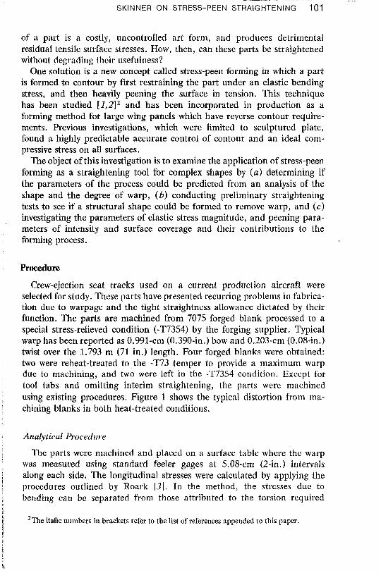
selected for study. These parts have presented recurring problems in fabrica- tion due to warpage and the tight straightness allowance dictated by their function, The parts are machined from 7075 forged blank processed to a special stress-relieved condition (-T7354) by the forging supplier. Typical warp has been reported as 0.991-cm (0.390-in.) bow and 0.203-cm (0.08-in,) twist over the 1.793 m (71 in.) length. Four forged blanks were obtained: two were reheat-treated to the -T73 temper to provide a nlaximum warp due to machining, and two were left in the -T7354 condition. Except for tool tabs and omitting interim straightening, the parts were machined using existing procedures. Figure 1 shows the typical distortion from ma- chining blanks in both heat-treated conditions.
Analytical Procedure
11e parts were machined and placed on a surface table where the warp was measured using standard feeler gages at 5.08-cm (2-in.) intervals
; along each side. The longitudinal stresses were calculated by applying the I i procedures outlined by Roark [3]. In the method, the stresses due to
bending can be separated from those attributed to the torsion required i.'
' h he italic numbers in brackets refer to the list of references appended to this paper. i t
I i
FIG. 1- Distortion resulting from nlachiniug a part from a -T7354 (top) and -73 (bottom) forged blank.
to remove the twist. Later, the longitudinal component of torsion can be added to the bending stresses to find the total longitudinal stresses required to restrain the part in the flat position. Since these stresses are elastic, strength-of-materials equations apply, therefore
Y = &st;\nct. fro111 the neutral axis to the poult in question, 6 = amount of de'rlection, L = chord length across the deflection, and
. , E = 5;::::: ::-:,:*. A:
T = torque required ro unnvisr rhe shape. \t j I \? KG. 1 = moment arm to the point in question,
I
SKINNER ON STRESS-PEEN STRAIGHTENING 103
K = shape factor, G = torsion modulus, J = polar moment of inertia, O = angle of twist at each section, and
W = width of cross section at each section.
Then the total longitudinal stresses in the restrained position are
The elastic prestress required to overcome the restraining stress is simply
and by employing the elastic bending relationships in a slightly different form the prestress radius is calculated as
In order that the mathematical model describing the various stress states in the part can be developed, the stress moments about the neutral axis must be considered, since for the part to lie flat
where
C nz = sum of the moment, and NA = neutral axis.
There are four stresses that must be included in the analysis: ((2) restraining stress (GR tension), (b) elastic prestress (GE tension), (c) stresses due to shotpeen (or compression), and ( d ) springback (as compression). 'lhree of the stresses (OR, OE, and crs) are elastic, and their stress diagrams through the cross section are linear. Consequently, the stress moment is a triangle and can be stated
1 moment = - Y
3
Bur runlwcrulLll Y TOPICS-METALLIC MATERIALS
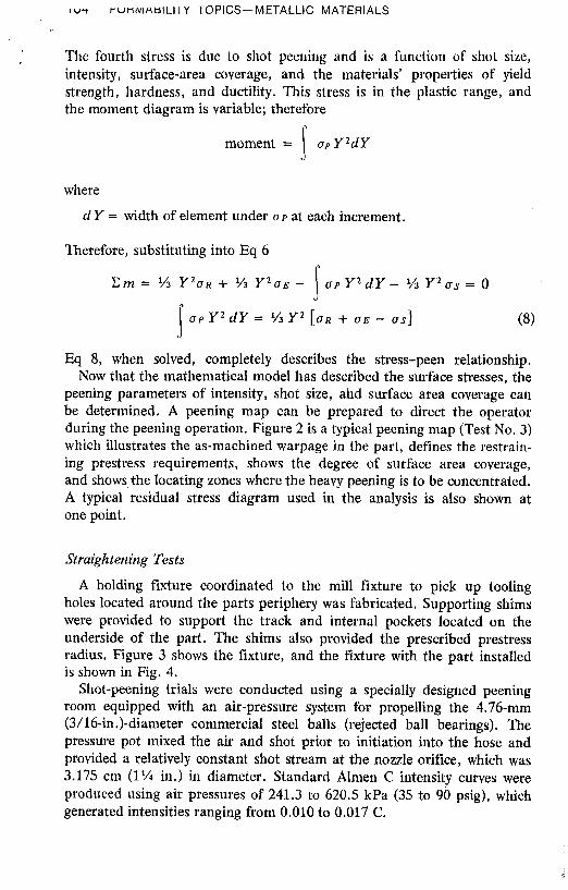
The fourth stress is due to shot peening and is a function of shot size, intensity, surface-area coverage, and the materials' properties of yield strength, hardness, and ductility. This stress is in the plastic range, and the moment diagram is variable; therefore
moment = u p Y2dY I where
d Y = width of element under o p at each increment.
Therefore, substituting into Eq 6
E m = % Y 2 a ~ + % Y 2 0 ~ - a p Y 2 d Y - % Y 2 u s = 0 .I .I u p y2 d Y = i/J y2 [OR + o~ - os] (8)
Eq 8, when solved, completely describes the stress-peen relationship. Now that the mathematical model has described the surface stresses, the
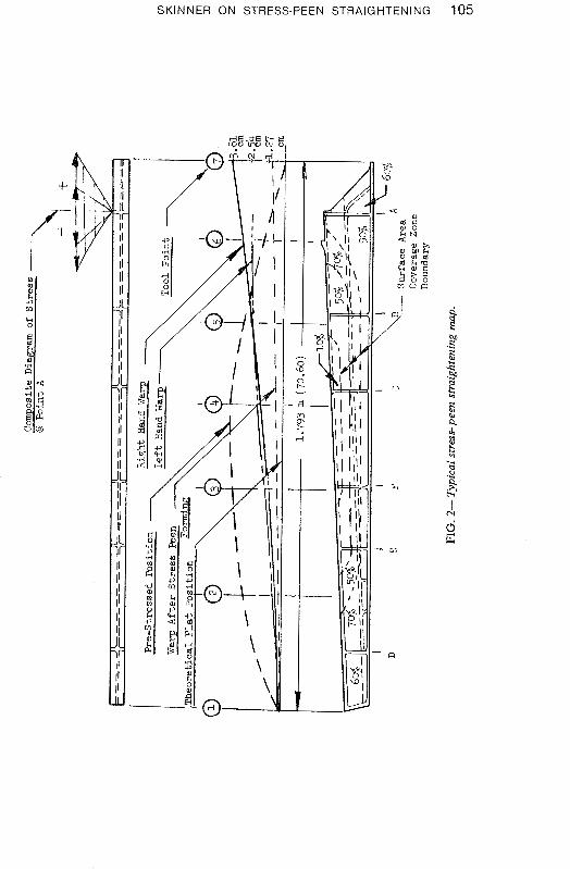
peening parameters of intensity, shot size, ahd surface area coverage can be determined. A peening map can be prepared to direct the operator during the peening operation. Figure 2 is a typical peening map (Test No. 3) which illustrates the as-machined warpage in the part, defines the restrain- ing prestress requirements, shows the degree of surface area coverage, and shows, the locating zones where the heavy peening is to be concentrated, A typical residual stress diagram used in the analysis is also shown at one point.
Straightening Tests
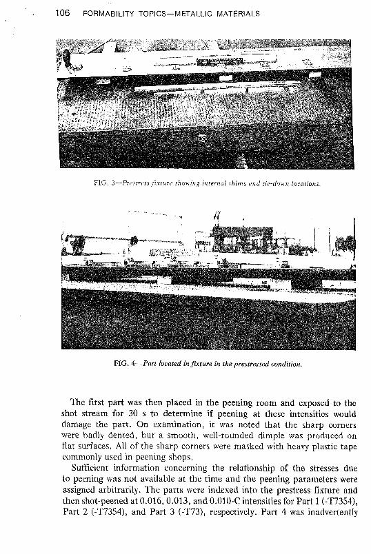
A holding fixture coordinated to the mill fixture to pick up tooling holes located around the parts periphery was fabricated. Supporting shims were provided to support the track and internal pockets located on the underside of the part. The shims also provided the prescribed prestress radius. Figure 3 shows the fixture, and the fixture with the part installed is shown in Fig. 4.
Shot-peening trials were conducted using a specially designed peening room equipped with an air-pressure system for propelling the 4.76-mm (3/16-in.)-diameter commercial steel balls (rejected ball bearings). The pressure pot mixed the air and shot prior to initiation into the hose and provided a relatively constant shot stream at the nozzle orifice, which was 3.175 cm (1% in.) in diameter. Standard Almen C intensity curves were produced using air pressures of 241.3 to 620.5 kPa (35 to 90 psig), which generated intensities ranging from 0.010 to 0.017 C .
SKINNER ON STRESS-PEEN STRAIGHTENING 105
106 FORMABILITY TOPICS-METALLIC MATERIALS
FIG. 3-Presrress .rirrurt. showing inrernal shims and rie-down locarions.
FIG. 4-Part located in fucture in the prestressed condition.
The first part was then placed in the peening room and exposed to the shot stream for 30 s to determine if peening at these intensities would damage the part. On examination, it was noted that the sharp corners were badly dented, but a smooth, well-rounded dimple was produced on flat surfaces. All of the sharp corners were masked with heavy plastic tape commonly used in peening shops.
Sufficient information concerning the relationship of the stresses due to peening was not available at the time and the peening parameters were assigned arbitrarily. The parts were indexed into the prestress fixture and then shot-peened at 0.016,0.013, and 0.010-C intensities for Part 1 (-T7354), Part 2 (-T7354), and Part 3 (-T73), respectively. Part 4 was inadvertently
SKINNER ON STRESS-PEEN STRAIGHTENING 107
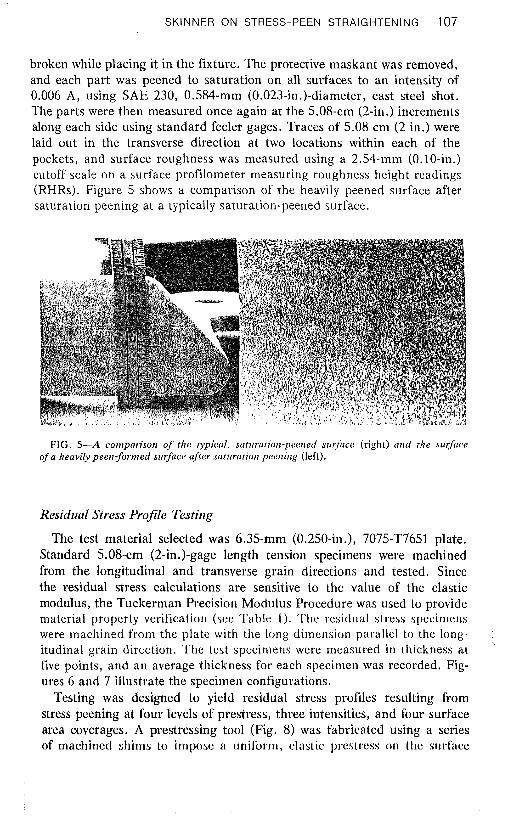
broken while placing it in the fixture. The protective maskant was removed, and each part was peened to saturation on all surfaces to an intensity of 0.006 A, using SAE 230, 0.584-mm (0.023-in.)-diameter, cast steel shot. l 'he parts were then measured once again at the 5.08-cm (2-in.) increments along each side using standard feeler gages. Traces of 5.08 cm (2 in.) were laid out in the transverse direction at two locations within each of the pockets, and surface roughness was measured using a 2.54-mm (0.10-in.) cutoff scale on a surface profilometer measuring roughness height readings (RHRs). Figure 5 shows a comparison of the heavily peened surface after saturation peening at a typically saturation-peened surface.
FIG. 5-A conzparisoir of the typical, smtumtion-peened stuj'nce (right) and the stlrjhce of n heavily peen-formed surface after sattrrutiorz peening (left).
Residual Stress Profile Testing
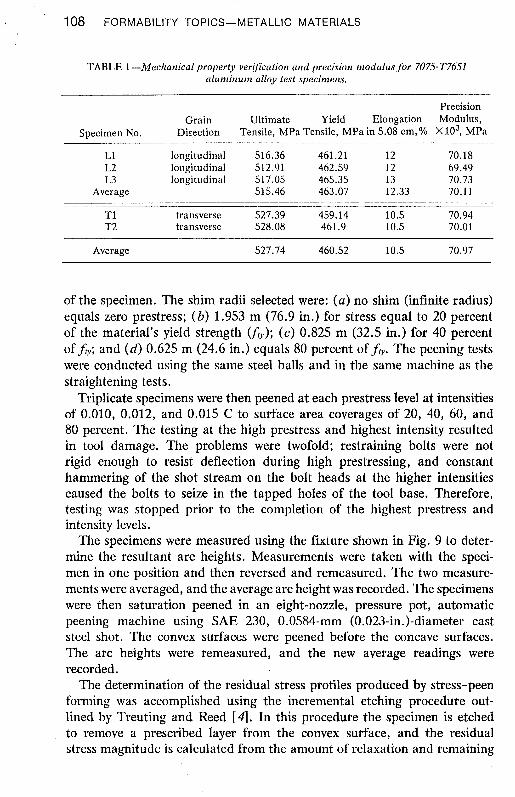
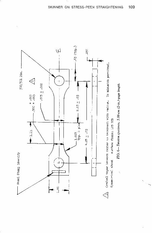
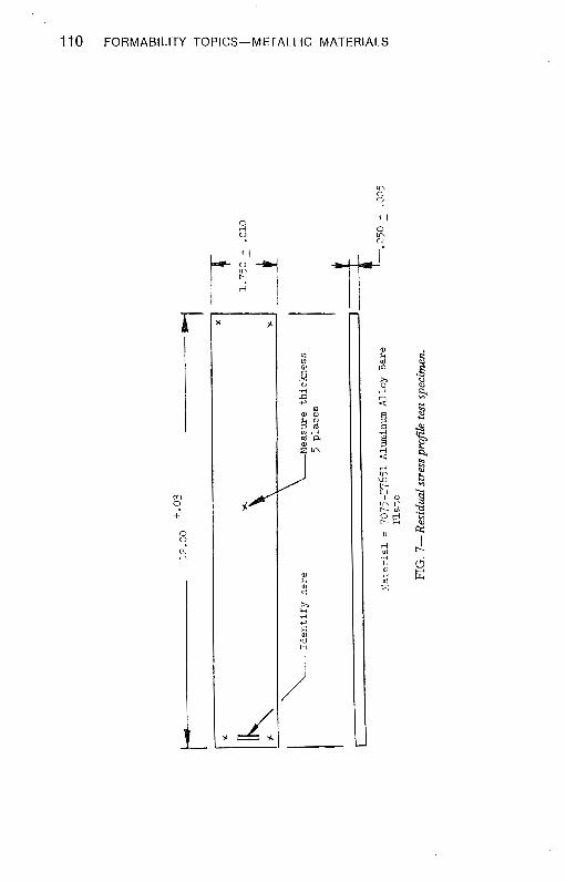
The test material selected was 6.35-mm (0.250-in.), 7075-T7651 plate. Standard 5.08-cm (2-in.)-gage length tension specimens were machined from the longitudinal and transverse grain directions and tested. Since the residual stress calculations are sensitive to the value of the elastic modulus, the Tuckerman Precision Modulus Procedure was used to provide material property verification (see Table 1 ) . The residual stress specimens were machined from the plate with the long dimension parallel to the long- itudinal grain direction. The test specimens were measured in thickness at '
five points, and an average thickness for each specimen was recorded. Fig- ures 6 and 7 illustrate the specimen configurations.
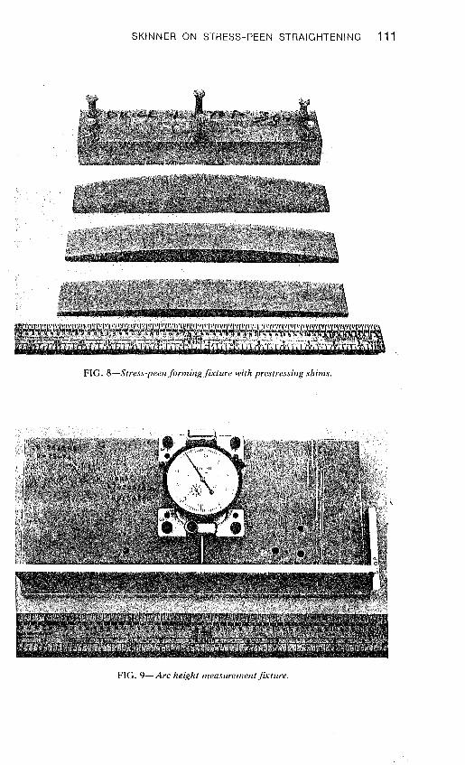
Testing was designed to yield residual stress profiles resulting from stress peening at four levels of prestress, three intensities, and four surface area coverages. A prestressing tool (Fig. 8) was fabricated using a series of machined shims to impose a uniform, elastic prestress on the surface
108 FORMABILITY TOPICS-METALLIC MATERIALS
TABLE 1 -Meclraiiical property verijicatioii and precision inodulus for 7075T7651 aluminum alloy test specimens.
of the specimen. The shim radii selected were: ( a ) no shim (infinite radius) equals zero prestress; (b) 1.953 m (76.9 in.) for stress equal to 20 percent of the material's yield strength (&); (c) 0.825 m (32.5 in.) for 40 percent of fv; and (d) 0.625 m (24.6 in.) equals 80 percent of ft,. The peening tests were conducted using the same steel balls and in the same machine as the straightening tests.
Triplicate specimens were then peened at each prestress level at intensities of 0,010, 0.012, and 0.015 C to surface area coverages of 20, 40, 60, and 80 percent. The testing at the high prestress and highest intensity resulted in tool damage. The problems were twofold; restraining bolts were not rigid enough to resist deflection during high prestressing, and constant hammering of the shot stream on the bolt heads at the higher intensities caused the bolts to seize in the tapped holes of the tool base. Therefore, testing was stopped prior to the completion of the highest prestress and intensity levels.
The specimens were measured using the fixture shown in Fig, 9 to deter- mine the resultant arc heights. Measurements were taken with the speci- men in one position and then reversed and remeasured. The two measure- ments were averaged, and the average arc height was recorded. The specimens were then saturation peened in an eight-nozzle, pressure pot, automatic peening machine using SAE 230, 0.0584-mm (0.023-in.)-diameter cast steel shot. The convex surfaces were peened before the concave surfaces. The arc heights were remeasured, and the new average readings were recorded.
The determination of the residual stress profiles produced by stress-peen forming was accomplished using the incremental etching procedure out- lined by Treuting and Reed [4 ] . In this procedure the specimen is etched to remove a prescribed layer from the convex surface, and the residual stress magnitude is calculated from the amount of relaxation and remaining
SKINNER ON STRESS-PEEN STRAIGHTENING 109
I I O FORMABILITY TOPICS-METALLIC MATERIALS
SKINNER ON STRESS-PEEN STRAIGHTENING 11 1
FIG. 8-Stress-peen forming fisture with prestressitrg s'hitns.
FIG. 9-Arc height mensuremettt.fivt11re.
1 I 2 FORMABILITY TOPICS-METALLIC MATERIALS
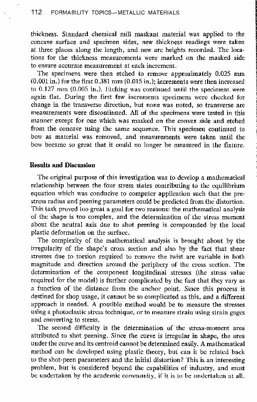
thickness. Standard chemical mill maskant material was applied to the ,concave surface and specimen sides, new thickness readings were taken at three places along the length, and new arc heights recorded. The loca- tions for the thickness measurements were marked on the masked side to ensure accurate measurement at each increment.
The specimens were then etched to remove approximately 0.025 mm (0.001 in.) for the first 0.381 mm (0.015 in.); increments were then increased to 0.127 mm (0.005 in.). Etching was continued until the specimens were again flat. During the first few increments specimens were checked for change in the transverse direction, but none was noted, so transverse arc measurements were discontinued. All of the specimens were tested in this manner except for one which was masked on the convex side and etched from the concave using the same sequence. This specimen continued to bow as material was removed, and measurements were taken until the bow became so great that it could no longer be measured in the fixture.
Results and Discussion
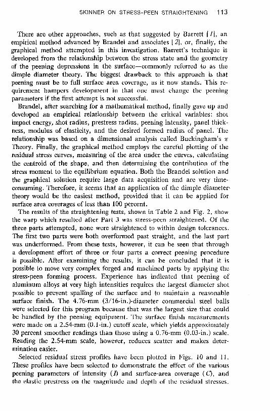
The original purpose of this investigation was to develop a mathematical relationship between the four stress states contributing to the equilibrium equation which was conducive to computer application such that the pre- stress radius and peening parameters could be predicted from the'distortion. This task proved too great a goal for two reasons: the mathematical analysis of the shape is too complex, and the determination of the stress moment about the neutral axis due to shot peening is compounded by the local plastic deformation on the surface,
The complexity of the mathematical analysis is brought about by the irregularity of the shape's cross section and also by the fact that shear stresses due to torsion required to remove the twist are variable in both magnitude and direction around the periphery of the cross section. The determination of the component longitudinal stresses (the stress value required for the model) is further complicated by the fact that they vary as a function of the distance from the anchor point. Since this process is destined for shop usage, it cannot be so complicated as this, and a different approach is needed. A possible method would be to measure the stresses using a photoelastic stress technique, or to measure strain using strain gages and converting to stress.
The second difficulty is the determination of the stress-moment area attributed to shot peening. Since the curve is irregular in shape, the area under the curve and its centroid cannot be determined easily. A mathematical method can be developed using plastic theoty, but can it be related back to the shot-peen parameters and the initial distortion? This is an interesting problem, but is considered beyond the capabilities of industry, and must be undertaken by the academic community, if it is to be undertaken at all.
SKINNER ON STRESS-PEEN STRAIGHTENING I 13
There are other approaches, such as that suggested by Barrett [lj, an empirical method advanced by Brandel and associates [ 2 ] , or, finally, the graphical method attempted in this investigation. Barrett's technique is developed from the relationship between the stress state and the geometry of the peening depressions in the surface-commonly referred to as the dimple diameter theory. The biggest drawback to this approach is that peening must be to full surface area coverage, as it now stands. This re- quirement hampers development in that one must change the peening parameters if the first attempt is not successful.
Brandel, after searching for a mathematical method, finally gave up and developed an empirical relationship between the critical variables: shot impad energy, shot radius, prestress radius, peening intensity, panel thick- ness, modulus of elasticity, and the desired formed radius of panel. The relationship was based on a dimensional analysis called Buckingham's n Theory. Finally, the graphical method employs the careful plotting of the residual stress curves, measuring of the area under the curves, calculating the centroid of the shape, and then determining the contribution of the stress moment to the equilibrium equation. Both the Brandel solution and the graphical solution require large data acquisition and are very time- consuming. Therefore, it seems that an application of the dimple diameter< theory would be the easiest method, provided that it can be applied for surface area coverages of less than 100 percent.
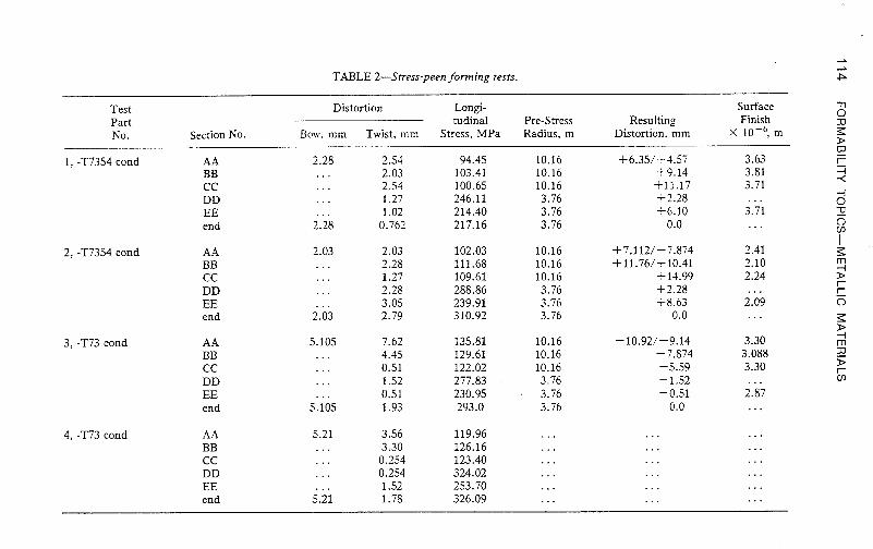
The results of the straightening tests, shown in Table 2 and Fig. 2, show the warp which resulted after Part 3 was stress-peen straightened. Of the three parts attempted, none were straightened to within design tolerances. The first two parts were both overformed past straight, and the last part was underformed. From these tests, however, it can be seen that through a development effort of three or four parts a correct peening procedure is possible. After examining the results, it can be concluded that it is possible to move very complex forged and machined parts by applying the stress-peen forming process. Experience has indicated that peening of aluminum alloys at very high intensities requires the largest diameter shot possible to prevent spalling of the surface and to maintain a reasonable surface finish. The 4.76-mm (3/ 16-in.)-diameter commercial steel balls were selected for this program because that was the largest size that could be handled by the peening equipment. The surface finish measurements were made on a 2.54-mm (0.1-in.) cutoff scale, which yields approxin~ately 30 percent smoother readings than those using a 0.76-mm (0.03-in.) scale. Reading the 2.54-mm scale, however, reduces scatter and makes deter- mination easier.
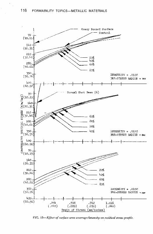
Selected residual stress profiles have been plotted in Figs. 10 and 11. These profiles have been selected to demonstrate the effect of the various peening parameters of intensity (1) and surface-area coverage (C), and the elastic prestress oti the magnitude and depth of thc rcsiduul stresses.
TABLE 2-Stress-peen forming tests.
Test Part No.
1, -T7354 cond
2 , -T7354 cond
3, -T73 cond
4, -T73 cond
Section No.
AA BB CC DD EE end
AA BB CC DD EE end
CC DD EE end
CC DD EE end
Distortion Longi- tudinal
Bow, mm Twist, mm Stress, MPa Pre-Stress Resulting Radius, m Distortion, mm
Surface Finish
X lov6, m
3.63 3.81 3.71
SKINNER ON STRESS-PEEN STRAIGHTENING 115
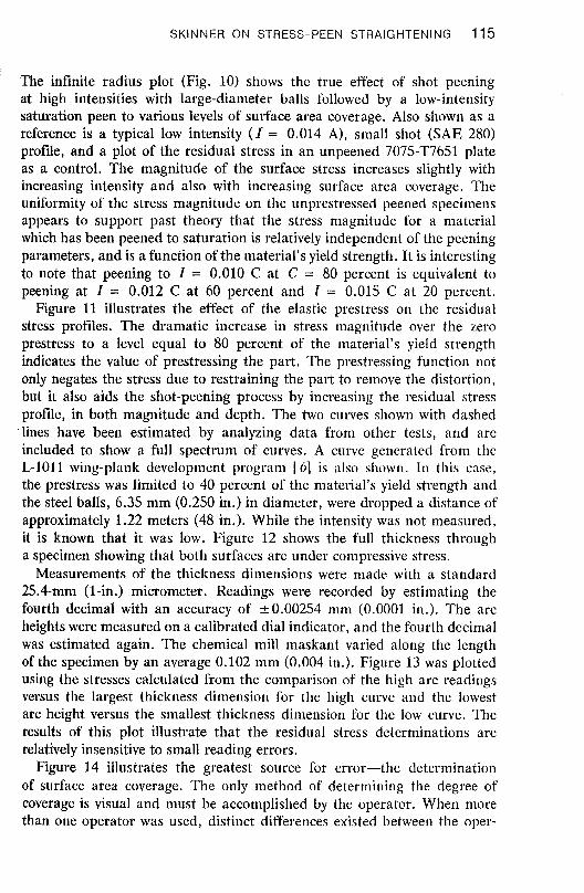
The infinite radius plot (Fig. 10) shows the true effect of shot peening at high intensities with large-diameter balls followed by a low-intensity saturation peen to various levels of surface area coverage. Also shown as a reference is a typical low intensity ( I = 0.014 A), small shot (SAE 280) profrle, and a plot of the residual stress in an unpeened 7075-T7651 plate as a control. The magnitude of the surface stress increases slightly with increasing intensity and also with increasing surface area coverage. The uniformity of the stress magnitude on the unprestressed peened specimens appears to support past theory that the stress magnitude for a material which has been peened to saturation is relatively independent of the peening parameters, and is a function of the material's yield strength. It is interesting to note that peening to I = 0.010 C at C = 80 percent is equivalent to peening at I = 0.012 C at 60 percent and I = 0.015 C at 20 percent.
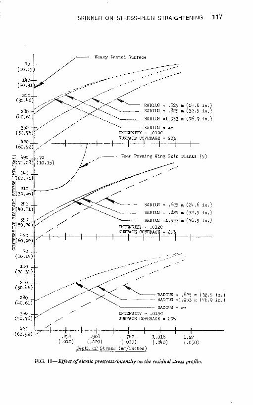
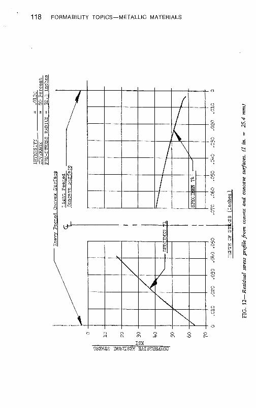
Figure 11 illustrates the effect of the elastic prestress on the residual stress profiles. The dramatic increase in stress magnitude over the zero prestress to a level equal to 80 percent of the material's yield strength indicates the value of prestressing the part, The prestressing function not only negates the stress due to restraining the part to remove the distortion, but it also aids the shot-peening process by increasing the residual stress profile, in both magnitude and depth. The two curves shown with dashed lines have been estimated by analyzing data from other tests, and are included to show a full spectrum of curves. A curve generated from the L-1011 wing-plank development program [ 61 is also shown. In this case, the prestress was limited to 40 percent of the material's yield strength and the steel balls, 6.35 mm (0.250 in.) in diameter, were dropped a distance of approximately 1.22 meters (48 in.). While the intensity was not measured, it is known that it was low. Figure 12 shows the full thickness through a specimen showing that both surfaces are under compressive stress.
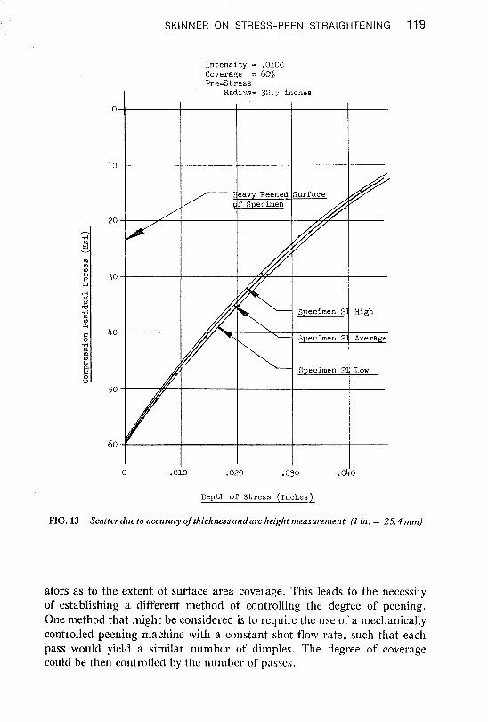
Measurements of the thickness dimensions were made with a standard 25.4-mm (1-in.) micrometer. Readings were recorded by estimating the fourth decimal with an accuracy of k0.00254 mm (0.0001 in.). The arc heights were measured on a calibrated dial indicator, and the fourth decimal was estimated again. The chemical mill maskant varied along the length of the specimen by an average 0.102 mm (0.004 in.). Figure 13 was plotted using the stresses calculated from the comparison of the high arc readings versus the largest thickness dimension for the high curve and the lowest arc height versus the smallest thickness dimension for the low curve. The results of this plot illustrate that the residual stress determinations are relatively insensitive to small reading errors.
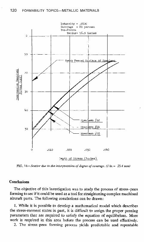
Figure 14 illustrates the greatest source for error-the determination of surface area coverage. The only method of determining the degree of coverage is visual and must be accomplished by the operator. When more than one operator was used, distinct differences existed between the oper-
1 16 FORMABILITY TOPICS-METALLIC MATERIALS
7 Heavy Peened S u r f a c e
INTENSITY = .OlOC RE-STRESS RADIUS = W
,--- Normal S h o t Peen (6)
I r m s m y = ,012~ PRE-STRESS RADIUS = ow
INTENSITY = ,015~ FRE-STRESS RADIUS - (xb
420 1 I I I I 1 I I I I
(60.92) 1
.254 .508 .762 1.016 ( ,010) ( ,020) ( .030) (.Ow
Depth of S t r e s s (mm/inches)
SKINNER ON STRESS-PEEN STRAIGHTENING 117
I /-- Heavy Peened Surface
RADIUS = .625 m - RADIW = .825 m
RADIUS =1.953 m
RADIUS = oo
(24.6 i n . ) (32.5 in . )
(76 .9 i n . )
i /--- Peen Forming Wing Skin Planks ( 5 )
RADIUS = .625 m (24.6 i n . )
RADI'LG = .825 ni (32.5 i n . )
RADIUS =1.951 m (76.9 i n - \
i n . ) i n . )
350 .
Depth of S t r e s s (mrn/inches)
~ ( 5 0 ~ 7 6 ) m " 420 B(60.92)
E 70
FIG. 1 l- Effect of elastic prestress Antensity on the residual stress profile.
/' -,,- -- , , - -, ---. ,
/ ,'
INTENSITY = .012C
I I SURFACE COVERAGE = 2%
// ' I 1 1 1 1 I
,
118 FORMABILITY TOPICS-METALLIC MATERIALS
SKINNER ON STRESS-PEEN STRAIGHTENING 119
I n t e n s i t y = ,010C Coverage = 60% Pre-Stress
Radius= 32.5 inches
\----1 specimen 24 ~ i g h
o . oio .020 .030 .oGo
Depth of S t r e s s ( ~ n c h e s )
FIG. 13- Scatter due to accuracy of thickness and arc height meusurernent. (1 in. = 25.4 mm)
ators as to the extent of surface area coverage. This leads to the necessity of establishing a different method of controlling the degree of peening. One method that might be considered is to require the use of a mechanically controlled peening machine with a constant shot flow rate, such that each pass would yield a similar number of dimples. The degree of coverage could be then controlled by t lic tiunibcr 01' passes.
120 FORMABILITY TOPICS-METALLIC MATERIALS
Depth of S t r e s s (~nchesi.
FIG. 14-Scatter due to the interpretation of degree of coverage. (1 in.= 25.4 mm)
Conclusions
The objective of this investigation was to study the process of stress-peen forming to see if it could be used as a tool for straightening complex machined aircraft parts. The following conclusions can be drawn:
1. While it is possible to develop a mathematical model which describes the stress-moment states in part, it is difficult to assign the proper peening parameters that are required to satisfy the equation of equilibrium. More work is required in this area before the process can be used effectively.
2. The stress-peen forming process yields predictable and repeatable
SKINNER ON STRESS-PEEN STRAIGHTENING 121
residual stress profiles through the part cross section when the surface area coverage is properly controlled.
3. It is possible to form a complex part with nonuniform cross sections using the stress-peen forming techniques.
References
[ I ] Bnrrett, Charles, "Shot-Peening Forming," oral presentation (wit11 ltandout), Westec, Los Angeles, Calif., March 1975.
[2] Brandel, W . W., et al, "Peen-Forming Titanium Panels," Technical Report AFML- TR-74-20, Air Force Materials Laboratory, Wright-Patterson AFB, Ohio, March 1974.
[3] Roark, R. J . ? Fornlulas for Stress and Strain, McGraw-Hill, New York, 1965. [4j Treuting, R. G. and Reed, W. T., Jr., Journul of Applied Physics, Vol. 22, Feb. 1951,
pp. 130-134. [ 5 j Gebhardt, F. L., "Determination of Residual Stress in Shot-Peened 7075 Aluminum,"
LR No. 231 16, Lockheed-California Company, Nov. 1969. [ 6 j Brown, W. A., "Residual Stresses Induced by Low-Intensity shot Peening of Bare 75STb
Aluminum Alloy," LR No. 8295, Lockheed-California Company, Feb. 1952.