Strictly Confidential (For Internal and Restricted Use only) Senior School Certificate Examination Marking Scheme - Physics (Code 55/1/1, Code 55/1/2, Code 55/1/3) 1. The marking scheme provides general guidelines to reduce subjectivity in the marking. The answers given in the marking scheme are suggested answers. The content is thus indicated. If a student has given any other answer, which is different from the one given in the marking scheme, but conveys the meaning correctly, such answers should be given full weightage. 2. In value based questions, any other individual response with suitable justification should also be accepted even if there is no reference to the text. 3. Evaluation is to be done as per instructions provided in the marking scheme. It should not be done according to one's own interpretation or any other consideration. Marking scheme should be adhered to and religiously followed. 4. If a question has parts, please award in the right hand side for each part. Marks awarded for different part of the question should then be totaled up and written in the left hand margin and circled. 5. If a question does not have any parts, marks are to be awarded in the left hand margin only. 6. If a candidate has attempted an extra question, marks obtained in the question attempted first should be retained and the other answer should be scored out. 7. No marks are to be deducted for the cumulative effect of an error. The student should be penalized only once. 8. Deduct ½ mark for writing wrong units, missing units, in the final answer to numerical problems. 9. Formula can be taken as implied from the calculations even if not explicitly written. 10. In short answer type question, asking for two features / characteristics / properties if a candidate writes three features, characteristics / properties or more, only the correct two should be evaluated. 11. Full marks should be awarded to a candidate if his / her answer in a numerical problem is close to the value given in the scheme. 12. In compliance to the judgement of the Hon’ble Supreme Court of India, Board has decided to provide photocopy of the answer book(s) to the candidates who will apply for it along with the requisite fee. Therefore, it is all the more important that the evaluation is done strictly as per the value points given in the marking scheme so that the Board could be in a position to defend the evaluation at any forum. 13. The Examiner shall also have to certify in the answer book that they have evaluated the answer book strictly in accordance with the value points given in the marking scheme and correct set of question paper. 14. Every Examiner shall also ensure that all the answers are evaluated, marks carried over to the title paper, correctly totaled and written in figures and words. 15. In the past it has been observed that the following are the common types of errors committed by the Examiners Leaving answer or part thereof unassessed in an answer script. Giving more marks for an answer than assigned to it or deviation from the marking scheme. Wrong transference of marks from the inside pages of the answer book to the title page. Wrong question wise totaling on the title page. Wrong totaling of marks of the two columns on the title page. Wrong grand total. Marks in words and figures not tallying. Wrong transference to marks from the answer book to award list. Answer marked as correct ( √) but marks not awarded. Half or part of answer marked correct ( √) and the rest as wrong (×) but no marks awarded. 16. Any unassessed portion, non carrying over of marks to the title page or totaling error detected by the candidate shall damage the prestige of all the personnel engaged in the evaluation work as also of the Board. Hence in order to uphold the prestige of all concerned, it is again reiterated that the instructions be followed meticulously and judiciously.
Transcript
Strictly Confidential (For Internal and Restricted Use only) Senior School Certificate Examination
Marking Scheme - Physics (Code 55/1/1, Code 55/1/2, Code 55/1/3) 1. The marking scheme provides general guidelines to reduce subjectivity in the marking. The
answers given in the marking scheme are suggested answers. The content is thus indicated. If a student has given any other answer, which is different from the one given in the marking scheme, but conveys the meaning correctly, such answers should be given full weightage.
2. In value based questions, any other individual response with suitable justification should also be accepted even if there is no reference to the text.
3. Evaluation is to be done as per instructions provided in the marking scheme. It should not be done according to one's own interpretation or any other consideration. Marking scheme should be adhered to and religiously followed.
4. If a question has parts, please award in the right hand side for each part. Marks awarded for different part of the question should then be totaled up and written in the left hand margin and circled.
5. If a question does not have any parts, marks are to be awarded in the left hand margin only. 6. If a candidate has attempted an extra question, marks obtained in the question attempted first
should be retained and the other answer should be scored out. 7. No marks are to be deducted for the cumulative effect of an error. The student should be
penalized only once. 8. Deduct ½ mark for writing wrong units, missing units, in the final answer to numerical problems. 9. Formula can be taken as implied from the calculations even if not explicitly written. 10. In short answer type question, asking for two features / characteristics / properties if a candidate
writes three features, characteristics / properties or more, only the correct two should be evaluated.
11. Full marks should be awarded to a candidate if his / her answer in a numerical problem is close to the value given in the scheme.
12. In compliance to the judgement of the Hon’ble Supreme Court of India, Board has decided to provide photocopy of the answer book(s) to the candidates who will apply for it along with the requisite fee. Therefore, it is all the more important that the evaluation is done strictly as per the value points given in the marking scheme so that the Board could be in a position to defend the evaluation at any forum.
13. The Examiner shall also have to certify in the answer book that they have evaluated the answer book strictly in accordance with the value points given in the marking scheme and correct set of question paper.
14. Every Examiner shall also ensure that all the answers are evaluated, marks carried over to the title paper, correctly totaled and written in figures and words.
15. In the past it has been observed that the following are the common types of errors committed by the Examiners
Leaving answer or part thereof unassessed in an answer script. Giving more marks for an answer than assigned to it or deviation from the marking
scheme. Wrong transference of marks from the inside pages of the answer book to the title page. Wrong question wise totaling on the title page. Wrong totaling of marks of the two columns on the title page. Wrong grand total. Marks in words and figures not tallying. Wrong transference to marks from the answer book to award list. Answer marked as correct ( √) but marks not awarded. Half or part of answer marked correct ( √) and the rest as wrong (×) but no marks
awarded. 16. Any unassessed portion, non carrying over of marks to the title page or totaling error detected by
the candidate shall damage the prestige of all the personnel engaged in the evaluation work as also of the Board. Hence in order to uphold the prestige of all concerned, it is again reiterated that the instructions be followed meticulously and judiciously.
SET: DELHI 55/1/1
Page 1 of 16 Final Draft March 22, 2017
MARKING SCHEME
Q. No. Expected Answer/ Value Points Marks Total
Marks
SECTION A
Q1
No,
Because the charge resides only on the surface of the conductor.
½
½
1
Q2
No,
As the magnetic field due to current carrying wire will be in the plane
of the circular loop, so magnetic flux will remain zero.
Alternatively
[Magnetic flux does not change with the change of current.]
½
½
1
Q3
BBBB
BB
EE
EH
260cos
cos
0
At equator 00
[Alternatively, Award full one mark, if student doesn’t take the value
(=2B)of while finding the value of horizontal component at equator, and just writes the formula only.]
½
½
1
Q4
Solar cell
1
1
Q5
Speed of em waves is determined by the ratio of the peak values of
electric and magnetic field vectors.
[Alternatively, Give full credit, if student writes directly
1
1
Q6
During charging, electric flux between the plates of capacitor keeps on
changing; this results in the production of a displacement current
between the plates.
1
1
2
Q7
It is the distance of charged particle from the centre of the nucleus, at
which the whole of the initial kinetic energy of the (far off) charged
particle gets converted into the electric potential energy of the system.
Distance of closest approach ) is given by
‘K’ is doubled, becomes
1
½
½
Explanation of flow of current through capacitor 1
Expression for displacement current 1
Definition of distance of closest approach 1
Finding of distance of closest approach when
Kinetic energy is doubled 1
SET: DELHI 55/1/1
Page 2 of 16 Final Draft March 22, 2017
[Alternatively: If a candidate writes directly
without mentioning
formula, award the 1 mark for this part.]
OR
1. According to Rutherford model, electron orbiting around the
nucleus, continuously radiates energy due to the acceleration;
hence the atom will not remain stable.
2. As electron spirals inwards; its angular velocity and frequency
change continuously; therefore it will emit a continuous spectrum.
1
1
2
2
Q8
Radius of ground state of hydrogen atom =0.53 = 0.53 x
According to de Broglie relation For ground state n=1
2 x 3.14 x 0.53 x =
m
Alternatively
Velocity of electron, in the ground state, of hydrogen atom
=
Hence momentum of revolving electron
p = m
= 9
m
[Note: Also accept the following answer:
Let be the wavelength of the electron in the orbit, we then have
For ground state n=1
(r= is the radius of the ground state)
[Alternatively
and (velocity of electron in ground state)
½
½
½
½
½
½
½
½
1
1
1
1
2
2
2
2
Calculation of wavelength of electron in ground state 2
Two important limitations of Rutherford nuclear model 1+1
SET: DELHI 55/1/1
Page 3 of 16 Final Draft March 22, 2017
Q9
Magnifying power is defined as the angle subtended at the eye by the image
to the angle subtended (at the unaided eye) by the object.
(Alternatively: Also accept this definition in the form of formula)
To increase the magnifying power both the objective and eyepiece must have
short focal lengths
1
½ +½
2
Q10
Broadcast / point to point, mode of communication
Space wave propagation
Above 40
Because e.m. waves, of frequency above 40MHz, are not reflected back by
the ionosphere / penetrate through the ionosphere.
½
½
½
½
2
SECTION C
Q11
(i) =100
= 500
Phase angle
= -1
As , ( /phase angle is negative), hence current leads voltage
(ii) To make power factor unity
= 100
½
½
½
½
(i) Calculation of phase difference between current and voltage 1
Name of quantity which leads ½
(ii) Calculation of value of ‘C’, is to be connected in parallel 1 ½
Name of basic mode of communication ½
Type of wave propagation ½
Range of frequencies and reason ½ + ½
Definition of magnifying power 1
Reason for short focal lengths of objective and eyepiece 1
Explanation of Short Focal Lengths 1
SET: DELHI 55/1/1
Page 4 of 16 Final Draft March 22, 2017
½
½
3
Q12
Diffusion
Drift
Due to the diffusion of electrons and holes across the junction a region of
(immobile) positive charge is created on the n-side and a region of
(immobile) negative charge is created on the p-side, near the junction; this is
called depletion region.
Barrier potential is formed due to loss of electrons from n-region and gain of
electrons by p-region. Its polarity is such that it opposes the movement of
charge carriers across the junction.
½
½
1
½
½
3
Q13
(i)
Frequency of revolution( ) =
½
½
½
(i) Derivation of the expression for cyclotron frequency 2
(ii) Reason / justification for the correct answer 1
Names of the two processes ½ + ½
Diagram 1
Explanation of formation of depletion region and Barrier Potential ½ + ½
SET: DELHI 55/1/1
Page 5 of 16 Final Draft March 22, 2017
(ii) No
The mass of the two particles, i.e deuteron and proton, is different.
Since (cyclotron) frequency depends inversely on the mass, they cannot
be accelerated by the same oscillator frequency.
½
½
½
3
Q14
(i) Einstein’s Photoelectric equation is
When a photon of energy is incident on the metal, some part of this
energy is utilized as work function to eject the electron and remaining
energy appears as the kinetic energy of the emitted electron.
(ii)
V
= 3.77 eV
The work function of and Ni is more than the energy of the incident
photons; so photoelectric emission will not take place from these metals.
Kinetic energy of photo electrons will not change, only photoelectric current
will change.
½
1
½
½
½
3
Q15
Resistance between points A & C
Effective resistance between points A & B
Current drawn from the voltage source,
I =
½
½
½
(i) Explanation of emission of electrons from the photosensitive surface 1½ (ii) Identification of metal/s which does/do not cause photoelectric effect 1
/ photoelectric emission Effect produced ½
Derivation of expression of voltage across resistance R 3
SET: DELHI 55/1/1
Page 6 of 16 Final Draft March 22, 2017
Let current through R be
Voltage across R
=
=
.
=
½
½
½
3
Q16
It is the process of superposition of information/message signal over a
carrier wave in such a way that the amplitude of carrier wave is varied
according to the information signal/message signal.
Direct transmission, of the low frequency base band information
signal, is not possible due to the following reasons;
(i) Size of Antenna: For transmitting a signal, minimum height of
antenna should be
; with the help of modulation wavelength of
signal decreases, hence height of antenna becomes manageable.
(ii) Effective power radiated by an antenna:
Effective power radiated by an antenna varies inversely as ,
hence effective power radiated into the space, by the
antenna,increases.
(iii)To avoid mixing up of signals from different transmitters.
(Any two)
1
1
½ + ½
3
Q17
(i) Capacitors are in parallel
Capacitors are in series
= µF
= µF
(ii) Charge drawn from the source
½
½
Definition of amplitude modulation 1
Explanation of two factors justifying the need of modulation 2
(i) Calculation of equivalent capacitance 1
(ii)Calculation of charge and energy stored 1+1
SET: DELHI 55/1/1
Page 7 of 16 Final Draft March 22, 2017
Q = V,
=
Energy stored
=
J
=21 µ J
½
½
½
½
3
Q18
(i)
Let the point ‘P’ be at a distance ‘r’ from the mid point of the dipole.
Both are equal and their directions are as shown in the figure. Hence
net electric field
=
(ii) Stable equilibrium, /
Unstable equilibrium, /
½
½
½
½
½
(i) Derivation of expression of electric field on the equatorial line of
the dipole 2
(ii) Depiction of orientation for stable and unstable equilibrium ½ + ½
SET: DELHI 55/1/1
Page 8 of 16 Final Draft March 22, 2017
½
3
Q19
(i) A4 : Mass Number : 172 Atomic Number : 69
(ii) A : Mass Number :180 Atomic Number : 72
[Alternatively : Give full credit if student considers decay and find
atomic and mass numbers accordingly
Gives the values quoted above.
If the student takes decay
This would give the answers: (A4:172,69);(A:180,74)]
Basic nuclear process for decay
For decay
[Note: Give full credit of this part, if student writes the processes as
conversion of proton into neutron for decay and neutron into proton
for decay.]
½
½
½
½
½
½
3
Q20
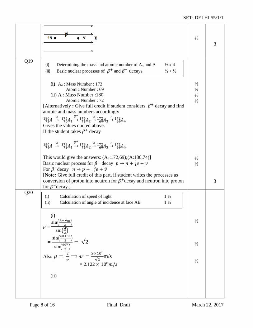
(i)
=
=
Also
m/s
= 2.122
(ii)
½
½
½
(i) Determining the mass and atomic number of A4 and A ½ x 4
(ii) Basic nuclear processes of and decays ½ + ½
(i) Calculation of speed of light 1 ½
(ii) Calculation of angle of incidence at face AB 1 ½
SET: DELHI 55/1/1
Page 9 of 16 Final Draft March 22, 2017
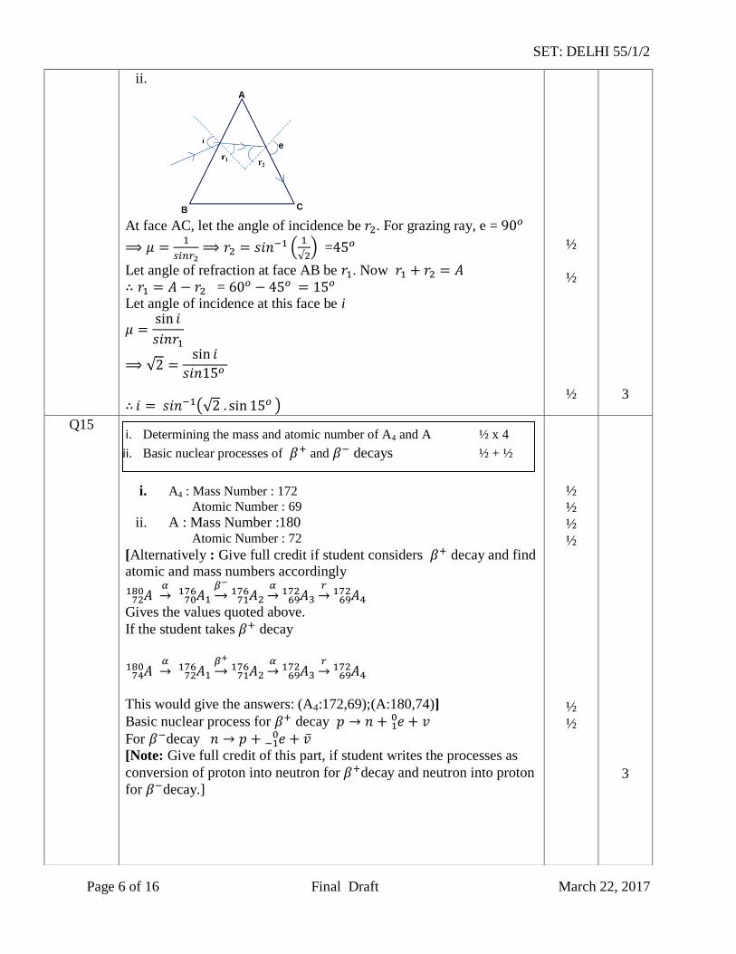
At face AC, let the angle of incidence be . For grazing ray, e =
=
Let angle of refraction at face AB be . Now
= Let angle of incidence at this face be i
½
½
½
3
Q21
Given =2kΩ
= 2 x Ω
= = 1m
current gain
Input signal voltage
= 1 x Ω
=
[Note : Give full credit if student calculates the required quantities by any
other alternative method ]
½
½
½
½
½
½
3
Q22
Working Principle of moving coil galvanometer 1
Necessity of (i) radial magnetic field ½
(ii) cylindrical soft iron core ½
Expression for current sensitivity ½
Explanation of use of Galvanometer to measure current ½
Calculation of collector current and input
1+1+1
SET: DELHI 55/1/1
Page 10 of 16 Final Draft March 22, 2017
When a coil, carrying current, and free to rotate about a fixed axis, is placed in a uniform magnetic field, it experiences a torque (which is
balanced by a restoring torque of suspension).
(i) To have deflection proportional to current / to maximize the
deflecting torque acting on the current carrying coil.
(ii) To make magnetic field radial / to increase the strength of
magnetic field.
Expression for current sensitivity
where is the deflection of the coil No
The galvanometer, can only detect currents but cannot measure them
as it is not calibrated. The galvanometer coil is likely to be damaged
by currents in the (mA/A) range]
OR
Self inductance of a coil equals, the magnitude of the magnetic flux,
linked with it, when a unit current flows through it.
Alternatively
Self inductance, of a coil, equals the magnitude of the emf induced in
it, when the current in the coil, is changing at a unit rate.
SI unit : henry / (weber/ampere) / (ohm second.)
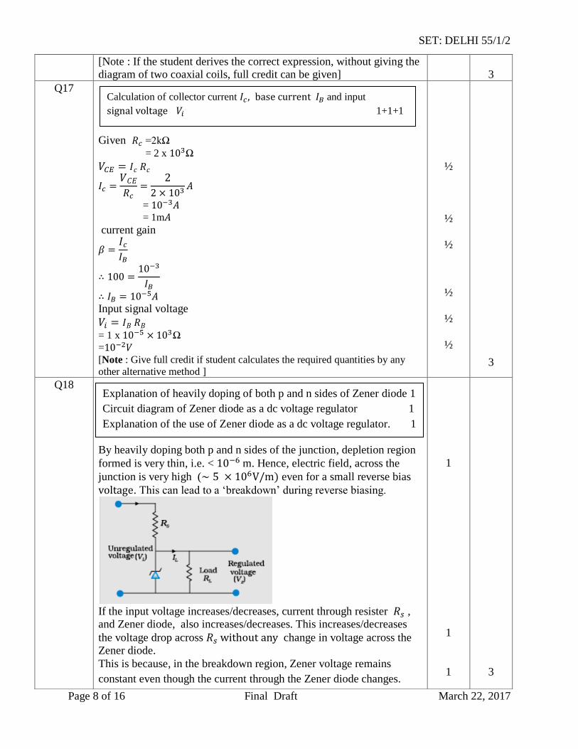
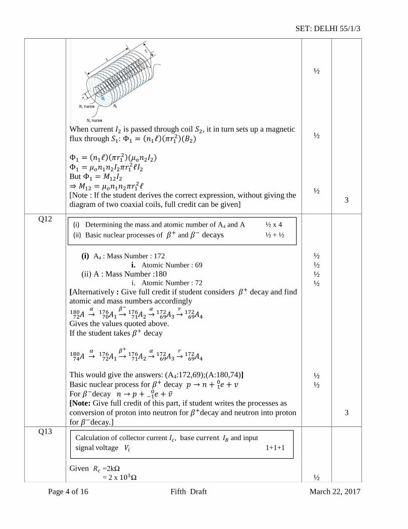
When current is passed through coil , it in turn sets up a magnetic
flux through :
But
[Note : If the student derives the correct expression, without giving the
diagram of two coaxial coils, full credit can be given]
1
½
½
½
½
1
½
½
½
½
3
3
a) Definition of self inductance and its SI unit 1 + ½
b) Derivation of expression for mutual inductance 1 ½
SET: DELHI 55/1/1
Page 11 of 16 Final Draft March 22, 2017
SECTION D
Q23
a) Anuja : Scientific temperament, co-operative, knowledgeable (any
two)
Mother : Inquisitive, scientific temper/keen to learn/has no airs(any
two)(or any other two similar values)
b)
As the refractive index of plastic material is less than that of glass
material therefore, for the same power ( , the radius of currature
of plastic material is small.
Therefore plastic lens is thicker.
Alternatively, If student just writes that plastic has a different
refractive index than glass, award one mark for this part.
½+ ½
½ + ½
½
½
½
½
4
SECTION E
Q24
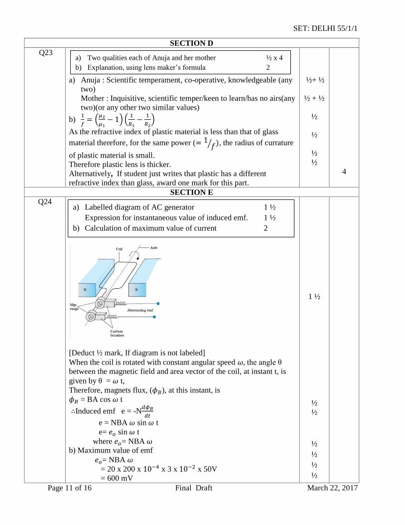
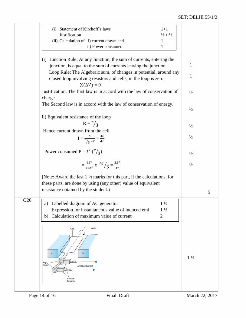
[Deduct ½ mark, If diagram is not labeled]
When the coil is rotated with constant angular speed the angle θ
between the magnetic field and area vector of the coil, at instant t, is
given by θ = t,
Therefore, magnets flux, ( ), at this instant, is
= BA cos t
Induced emf e = -N
e = NBA sin t
e= sin t
where = NBA b) Maximum value of emf
= NBA
= 20 x 200 x x 3 x x 50V
= 600 mV
1 ½
½
½
½
½
½
½
a) Two qualities each of Anuja and her mother ½ x 4
b) Explanation, using lens maker’s formula 2
a) Labelled diagram of AC generator 1 ½
Expression for instantaneous value of induced emf. 1 ½
b) Calculation of maximum value of current 2
SET: DELHI 55/1/1
Page 12 of 16 Final Draft March 22, 2017
Maximum induced current =
mA
[Note 1: It the student calculates the value of the maximum induced
emf and says that “ since R is not given, the value of maximum
induced current cannot be calculated”, the ½ mark, for the last part, of
the question, can be given.]
[Note 2: The direction of magnetic field has not been given. If the
student takes this direction along the axis of rotation and hence obtains
the value of induced emf and, therefore, maximum current, as zero,
award full marks for this part.]
OR
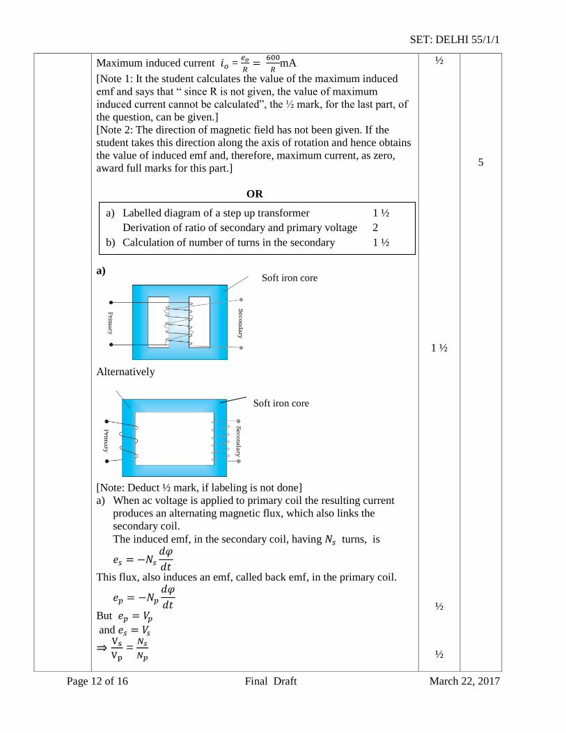
a)
Alternatively
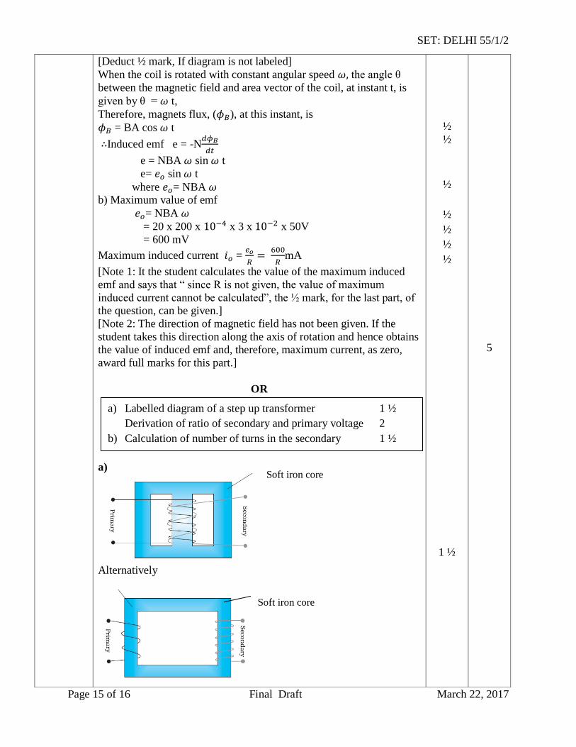
[Note: Deduct ½ mark, if labeling is not done]
a) When ac voltage is applied to primary coil the resulting current
produces an alternating magnetic flux, which also links the
secondary coil.
The induced emf, in the secondary coil, having turns, is
This flux, also induces an emf, called back emf, in the primary coil.
But
and
=
½
1 ½
½
½
5
Soft iron core
Soft iron core
a) Labelled diagram of a step up transformer 1 ½
Derivation of ratio of secondary and primary voltage 2
b) Calculation of number of turns in the secondary 1 ½
SET: DELHI 55/1/1
Page 13 of 16 Final Draft March 22, 2017
For an ideal transformer
=
=
b)
=
=
= 300
½
½
½
½
½
5
Q25
a) In an unpolarized light, the oscillations, of the electric field, are in
random directions, in planes perpendicular to the direction of
propagation. For a polarized light, the oscillations are aligned
along one particular direction.
Alternatively
Polarized light can be distinguished, from unpolarized light, when it is
allowed to pass through a polaroid. Polarized light does can show
change in its intensity, on passing through a Polaroid; intensity
remains same in case of unpolarized light.
When unpolarised light wave is incident on a polaroid, then the
electric vectors along the direction of its aligned molecules, get
absorbed; the electric vector, oscillating along a direction
perpendicular to the aligned molecules, pass through. This light is
called linearly polarized light.
b) According to Malus’ Law:
I =
I = (
, where is the intensity of unpolarized light.
(given)
I =
=
1
1
1
1
½
a) Distinction between unpolarised and linearly polarized
light 2
Obtaining linearly polarized Light 1
b) Calculation of intensely of light 2
SET: DELHI 55/1/1
Page 14 of 16 Final Draft March 22, 2017
=
OR
a)
Interference Pattern Diffraction pattern
1) All fringes are of equal width. 1) Width of central maxima is
twice the width of higher
order bands.
2) Intensity of all bright bands is
equal.
2) Intensity goes on
decreasing for higher order of
diffraction bands.
[Note: Also accept any other two correct distinguishing features.]
b) Angular width of central maximum
=
radian
= radian
Linear width of central maxima in the diffraction pattern
Let ‘n’ be the number of interference fringes which can be
accommodated in the central maxima
[Award the last ½ mark if the student writes the answers as 2 (taking
d=a), or just attempts to do these calculation.]
½
1+1
½
½
1
½
½
5
5
Q26
i. Derivation of the expression for drift velocity 2
Deduction of Ohm’s law 2
ii. Name of quantity and justification ½ + ½
a) Explanation of two features (distinguishing between
interference pattern and diffraction pattern.) 2
b) Calculation of angular width of central maxima 2
Estimation of number of fringes 1
SET: DELHI 55/1/1
Page 15 of 16 Final Draft March 22, 2017
Let an electric field E be applied the conductor. Acceleration of each electron is
Velocity gained by the electron
Let the conductor contain n electrons per unit volume. The average
value of time , between their successive collisions, is the relaxation
time,
Hence average drift velocity
The amount of charge, crossing area A, in time is
= Substituting the value of , we get
,
But I = JA, where J is the current density
J =
J =
This is Ohm’s law
[Note : Credit should be given if the student derives the alternative
form of Ohm’s law by substituting E =
]
ii) Electric current well remain constant in the wire.
All other quantities, depend on the cross sectional area of the wire.
OR
(i) Junction Rule: At any Junction, the sum of currents, entering the
junction, is equal to the sum of currents leaving the junction.
Loop Rule: The Algebraic sum, of changes in potential, around any
closed loop involving resistors and cells, in the loop is zero.
= 0
Justification: The first law is in accord with the law of conservation of
charge.
The Second law is in accord with the law of conservation of energy.
ii) Equivalent resistance of the loop
½
½
½
½
½
½
½
½
½
½
1
1
½
½
5
(i) Statement of Kirchoff’s laws 1+1
Justification ½ + ½
(ii) Calculation of i) current drawn and 1
ii) Power consumed 1
SET: DELHI 55/1/1
Page 16 of 16 Final Draft March 22, 2017
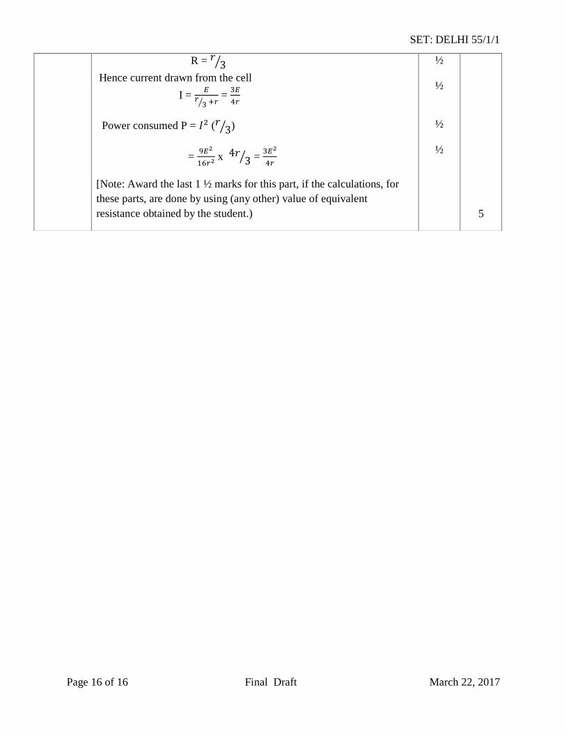
R =
Hence current drawn from the cell
I =
=
Power consumed P = ( )
=
x =
[Note: Award the last 1 ½ marks for this part, if the calculations, for
these parts, are done by using (any other) value of equivalent
resistance obtained by the student.)
½
½
½
½
5
SET: DELHI 55/1/2
Page 1 of 16 Final Draft March 22, 2017
MARKING SCHEME
Q. No. Expected Answer/ Value Points Marks Total
Marks
Q1
BBBB
BB
EE
EH
260cos
cos
0
At equator 00
[Alternatively, Award full one mark, if student doesn’t take the value
(=2B)of while finding the value of horizontal component at
equator, and just writes the formula only.]
½
½
1
Q2 Solar cell
1
1
Q3 No,
Because the charge resides only on the surface of the conductor.
½
½
1
Q4 Speed of em waves is determined by the ratio of the peak values of
electric and magnetic field vectors.
[Alternatively, Give full credit, if student writes directly
1
1
Q5 No,
As the magnetic field due to current carrying wire will be in the plane
of the circular loop, so magnetic flux will remain zero.
Alternatively
[Magnetic flux does not change with the change of current.]
½
½
1
Q6
Radius of nth
orbit
= 0.53 x 4
= 2.12
For an electron revolving in nth orbit, according to de Broglie relation
2 , For 1st excited state n = 2
n
= 6.67
Alternatively
velocity of electron in first excited state,
m
= 6.67 Alternatively
½
½
½
½
½
½
½
½
2
2
Calculation of wavelength of electron in first excited state 2
SET: DELHI 55/1/2
Page 2 of 16 Final Draft March 22, 2017
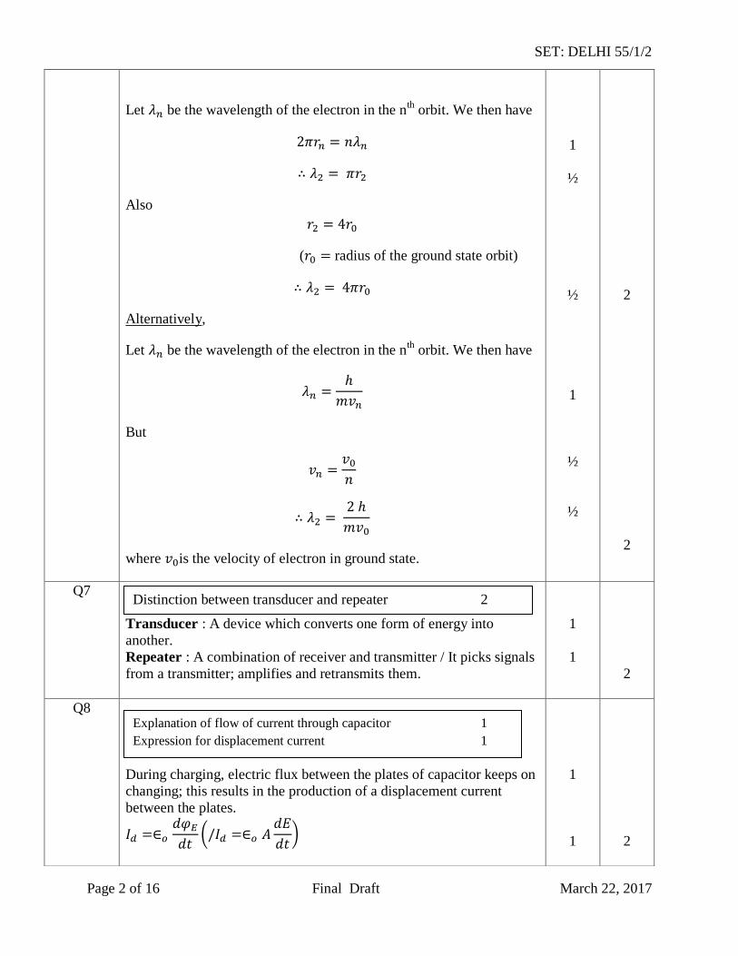
Let be the wavelength of the electron in the nth
orbit. We then have
Also
( radius of the ground state orbit)
Alternatively,
Let be the wavelength of the electron in the nth
orbit. We then have
But
where is the velocity of electron in ground state.
1
½
½
1
½
½
2
2
Q7
Transducer : A device which converts one form of energy into
another.
Repeater : A combination of receiver and transmitter / It picks signals
from a transmitter; amplifies and retransmits them.
1
1
2
Q8
During charging, electric flux between the plates of capacitor keeps on
changing; this results in the production of a displacement current
between the plates.
1
1
2
Distinction between transducer and repeater 2
Explanation of flow of current through capacitor 1
Expression for displacement current 1
SET: DELHI 55/1/2
Page 3 of 16 Final Draft March 22, 2017
Q9
It is the distance of charged particle from the centre of the nucleus, at
which the whole of the initial kinetic energy of the (far off) charged
particle gets converted into the electric potential energy of the system.
Distance of closest approach ) is given by
‘K’ is doubled, becomes
[Alternatively: If a candidate writes directly
without mentioning
formula, award the 1 mark for this part.]
OR
1. According to Rutherford model, electron orbiting around the
nucleus, continuously radiates energy due to the acceleration;
hence the atom will not remain stable.
2. As electron spirals inwards; its angular velocity and frequency
change continuously; therefore it will emit a continuous spectrum.
1
½
½
1
1
2
2
Q10
Large focal length : to increase magnifying power
Large aperature : to increase resolving power.
½
½
½
½
2
Q11
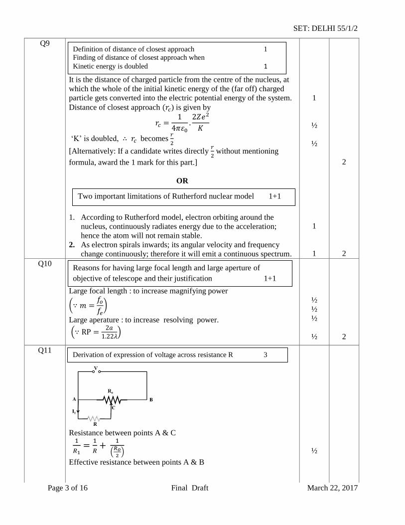
Resistance between points A & C
Effective resistance between points A & B
½
Reasons for having large focal length and large aperture of
objective of telescope and their justification 1+1
Definition of distance of closest approach 1
Finding of distance of closest approach when
Kinetic energy is doubled 1
Two important limitations of Rutherford nuclear model 1+1
Derivation of expression of voltage across resistance R 3
SET: DELHI 55/1/2
Page 4 of 16 Final Draft March 22, 2017
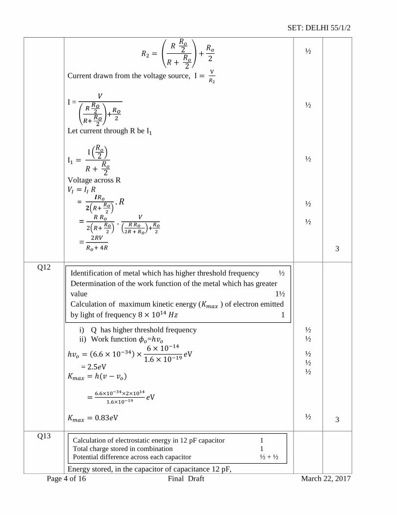
Current drawn from the voltage source,
I =
Let current through R be
Voltage across R
=
=
.
=
½
½
½
½
½
3
Q12
i) Q has higher threshold frequency
ii) Work function =
=
½
½
½
½
½
½
3
Q13
Energy stored, in the capacitor of capacitance 12 pF,
Identification of metal which has higher threshold frequency ½
Determination of the work function of the metal which has greater
value 1½
Calculation of maximum kinetic energy ( ) of electron emitted
by light of frequency 1
Calculation of electrostatic energy in 12 pF capacitor 1
Total charge stored in combination 1
Potential difference across each capacitor ½ + ½
SET: DELHI 55/1/2
Page 5 of 16 Final Draft March 22, 2017
=
J
= 1.5 J
C= Equivalent capacitance of 12 pF and 6 pF, in series, is given by
C = 4 pF
Charge stored across each capacitor
q = C V
= C
= 2 C
Charge on each capacitor 12 pF as well as 6 pF
Potential difference across capacitor
Potential difference across capacitor
½
½
½
½
½
½
3
Q14
i.
=
=
Also
m/s
= 2.122
½
½
½
i. Calculation of speed of light 1 ½
ii. Calculation of angle of incidence at face AB 1 ½
SET: DELHI 55/1/2
Page 6 of 16 Final Draft March 22, 2017
ii.
At face AC, let the angle of incidence be . For grazing ray, e =
=
Let angle of refraction at face AB be . Now
= Let angle of incidence at this face be i
½
½
½
3
Q15
i. A4 : Mass Number : 172 Atomic Number : 69
ii. A : Mass Number :180 Atomic Number : 72
[Alternatively : Give full credit if student considers decay and find atomic and mass numbers accordingly
Gives the values quoted above.
If the student takes decay
This would give the answers: (A4:172,69);(A:180,74)]
Basic nuclear process for decay
For decay
[Note: Give full credit of this part, if student writes the processes as
conversion of proton into neutron for decay and neutron into proton
for decay.]
½
½
½
½
½
½
3
i. Determining the mass and atomic number of A4 and A ½ x 4
ii. Basic nuclear processes of and decays ½ + ½
SET: DELHI 55/1/2
Page 7 of 16 Final Draft March 22, 2017
Q16
When a coil, carrying current, and free to rotate about a fixed axis, is
placed in a uniform magnetic field, it experiences a torque (which is
balanced by a restoring torque of suspension).
(i) To have deflection proportional to current / to maximize the
deflecting torque acting on the current carrying coil.
(ii) To make magnetic field radial / to increase the strength of
magnetic field.
Expression for current sensitivity
where is the deflection of the coil No
The galvanometer, can only detect currents but cannot measure them
as it is not calibrated. The galvanometer coil is likely to be damaged
by currents in the (mA/A) range]
OR
Self inductance of a coil equals, the magnitude of the magnetic flux,
linked with it, when a unit current flows through it.
Alternatively
Self inductance, of a coil, equals the magnitude of the emf induced in
it, when the current in the coil, is changing at a unit rate.
SI unit : henry / (weber/ampere) / (ohm second.)
When current is passed through coil , it in turn sets up a magnetic
flux through :
But
1
½
½
½
½
1
½
½
½
½
3
Working Principle of moving coil galvanometer 1
Necessity of (i) radial magnetic field ½
(ii) cylindrical soft iron core ½
Expression for current sensitivity ½
Explanation of use of Galvanometer to measure current ½
a) Definition of self inductance and its SI unit 1 + ½
b) Derivation of expression for mutual inductance 1 ½
SET: DELHI 55/1/2
Page 8 of 16 Final Draft March 22, 2017
[Note : If the student derives the correct expression, without giving the diagram of two coaxial coils, full credit can be given]
3
Q17
Given =2kΩ
= 2 x Ω
= = 1m
current gain
Input signal voltage
= 1 x Ω
=
[Note : Give full credit if student calculates the required quantities by any
other alternative method ]
½
½
½
½
½
½
3
Q18
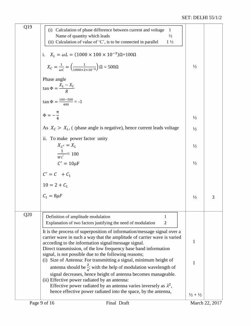
By heavily doping both p and n sides of the junction, depletion region
formed is very thin, i.e. < m. Hence, electric field, across the
junction is very high ( even for a small reverse bias . This can lead to a ‘breakdown’ during reverse biasing.
If the input voltage increases/decreases, current through resister , and Zener diode, also increases/decreases. This increases/decreases
the voltage drop across change in voltage across the Zener diode.
This is because, in the breakdown region, Zener voltage remains
constant even though the current through the Zener diode changes.
1
1
1
3
Explanation of heavily doping of both p and n sides of Zener diode 1
Circuit diagram of Zener diode as a dc voltage regulator 1
Explanation of the use of Zener diode as a dc voltage regulator. 1
Calculation of collector current and input
1+1+1
SET: DELHI 55/1/2
Page 9 of 16 Final Draft March 22, 2017
Q19
i. =100
= 500
Phase angle
= -1
As , ( /phase angle is negative), hence current leads voltage
ii. To make power factor unity
= 100
½
½
½
½
½
½
3
Q20
It is the process of superposition of information/message signal over a
carrier wave in such a way that the amplitude of carrier wave is varied
according to the information signal/message signal.
Direct transmission, of the low frequency base band information
signal, is not possible due to the following reasons;
(i) Size of Antenna: For transmitting a signal, minimum height of
antenna should be
; with the help of modulation wavelength of
signal decreases, hence height of antenna becomes manageable.
(ii) Effective power radiated by an antenna:
Effective power radiated by an antenna varies inversely as ,
hence effective power radiated into the space, by the antenna,
1
1
½ + ½
(i) Calculation of phase difference between current and voltage 1
Name of quantity which leads ½
(ii) Calculation of value of ‘C’, is to be connected in parallel 1 ½
Definition of amplitude modulation 1
Explanation of two factors justifying the need of modulation 2
SET: DELHI 55/1/2
Page 10 of 16 Final Draft March 22, 2017
increases. (iii)To avoid mixing up of signals from different transmitters.
(Any two)
3
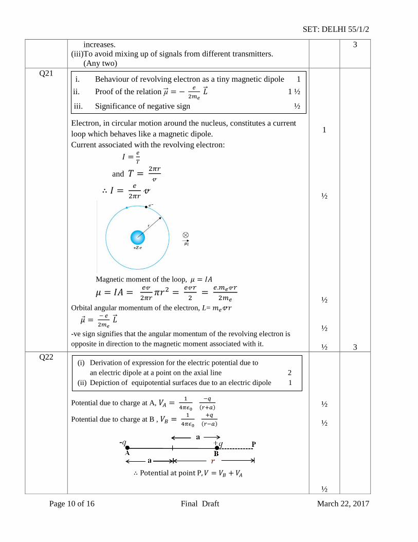
Q21
Electron, in circular motion around the nucleus, constitutes a current
loop which behaves like a magnetic dipole.
Current associated with the revolving electron:
and
Magnetic moment of the loop,
Orbital angular momentum of the electron, L=
-ve sign signifies that the angular momentum of the revolving electron is
opposite in direction to the magnetic moment associated with it.
1
½
½
½
½
3
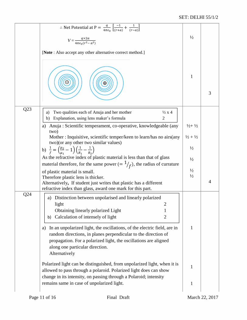
Q22
Potential due to charge at A,
Potential due to charge at B ,
½
½
½
i. Behaviour of revolving electron as a tiny magnetic dipole 1
ii. Proof of the relation
1 ½
iii. Significance of negative sign ½
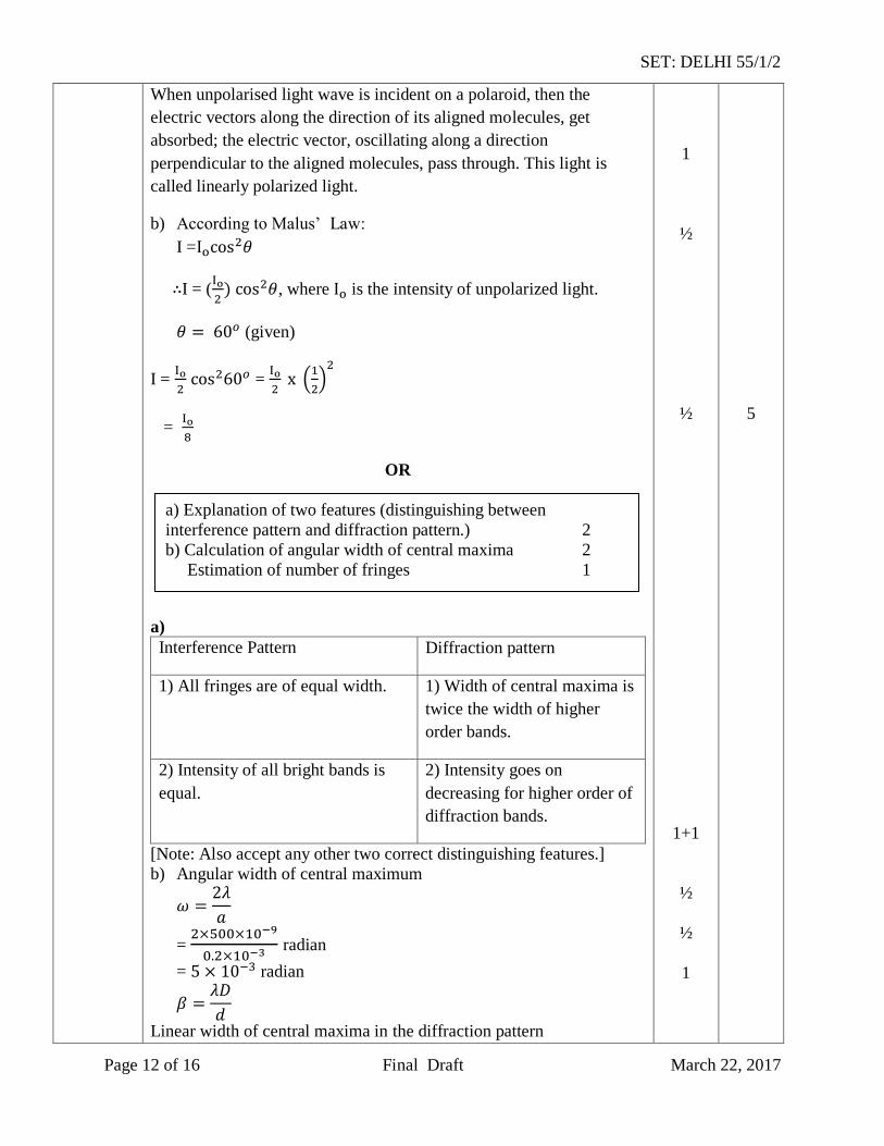
(i) Derivation of expression for the electric potential due to
an electric dipole at a point on the axial line 2
(ii) Depiction of equipotential surfaces due to an electric dipole 1
SET: DELHI 55/1/2
Page 11 of 16 Final Draft March 22, 2017
V =
[Note : Also accept any other alternative correct method.]
½
1
3
Q23
a) Anuja : Scientific temperament, co-operative, knowledgeable (any
two)
Mother : Inquisitive, scientific temper/keen to learn/has no airs(any
two)(or any other two similar values)
b)
As the refractive index of plastic material is less than that of glass
material therefore, for the same power ( , the radius of currature
of plastic material is small.
Therefore plastic lens is thicker.
Alternatively, If student just writes that plastic has a different
refractive index than glass, award one mark for this part.
½+ ½
½ + ½
½
½
½
½
4
Q24
a) In an unpolarized light, the oscillations, of the electric field, are in
random directions, in planes perpendicular to the direction of
propagation. For a polarized light, the oscillations are aligned
along one particular direction.
Alternatively
Polarized light can be distinguished, from unpolarized light, when it is
allowed to pass through a polaroid. Polarized light does can show
change in its intensity, on passing through a Polaroid; intensity
remains same in case of unpolarized light.
1
1
1
a) Two qualities each of Anuja and her mother ½ x 4
b) Explanation, using lens maker’s formula 2
a) Distinction between unpolarised and linearly polarized
light 2
Obtaining linearly polarized Light 1
b) Calculation of intensely of light 2
SET: DELHI 55/1/2
Page 12 of 16 Final Draft March 22, 2017
When unpolarised light wave is incident on a polaroid, then the
electric vectors along the direction of its aligned molecules, get
absorbed; the electric vector, oscillating along a direction
perpendicular to the aligned molecules, pass through. This light is
called linearly polarized light.
b) According to Malus’ Law:
I =
I = (
, where is the intensity of unpolarized light.
(given)
I =
=
=
OR
a)
Interference Pattern Diffraction pattern
1) All fringes are of equal width. 1) Width of central maxima is
twice the width of higher
order bands.
2) Intensity of all bright bands is
equal.
2) Intensity goes on
decreasing for higher order of
diffraction bands.
[Note: Also accept any other two correct distinguishing features.]
b) Angular width of central maximum
=
radian
= radian
Linear width of central maxima in the diffraction pattern
1
½
½
1+1
½
½
1
5
a) Explanation of two features (distinguishing between
interference pattern and diffraction pattern.) 2
b) Calculation of angular width of central maxima 2
Estimation of number of fringes 1
SET: DELHI 55/1/2
Page 13 of 16 Final Draft March 22, 2017
Let ‘n’ be the number of interference fringes which can be
accommodated in the central maxima
[Award the last ½ mark if the student writes the answers as 2 (taking
d=a), or just attempts to do these calculation.]
½
½
5
Q25
Let an electric field E be applied the conductor. Acceleration of each
electron is
Velocity gained by the electron
Let the conductor contain n electrons per unit volume. The average
value of time , between their successive collisions, is the relaxation
time,
Hence average drift velocity
The amount of charge, crossing area A, in time is
= Substituting the value of , we get
,
But I = JA, where J is the current density
J =
J = This is Ohm’s law
[Note : Credit should be given if the student derives the alternative
form of Ohm’s law by substituting E =
]
ii) Electric current well remain constant in the wire.
All other quantities, depend on the cross sectional area of the wire.
OR
½
½
½
½
½
½
½
½
½
½
5
i. Derivation of the expression for drift velocity 2
Deduction of Ohm’s law 2
ii. Name of quantity and justification ½ + ½
SET: DELHI 55/1/2
Page 14 of 16 Final Draft March 22, 2017
(i) Junction Rule: At any Junction, the sum of currents, entering the
junction, is equal to the sum of currents leaving the junction.
Loop Rule: The Algebraic sum, of changes in potential, around any
closed loop involving resistors and cells, in the loop is zero.
= 0
Justification: The first law is in accord with the law of conservation of
charge.
The Second law is in accord with the law of conservation of energy.
ii) Equivalent resistance of the loop
R =
Hence current drawn from the cell
I =
=
Power consumed P = ( )
=
x =
[Note: Award the last 1 ½ marks for this part, if the calculations, for
these parts, are done by using (any other) value of equivalent
resistance obtained by the student.)
1
1
½
½
½
½
½
½
5
Q26
1 ½
(i) Statement of Kirchoff’s laws 1+1
Justification ½ + ½
(ii) Calculation of i) current drawn and 1
ii) Power consumed 1
a) Labelled diagram of AC generator 1 ½
Expression for instantaneous value of induced emf. 1 ½
b) Calculation of maximum value of current 2
SET: DELHI 55/1/2
Page 15 of 16 Final Draft March 22, 2017
[Deduct ½ mark, If diagram is not labeled]
When the coil is rotated with constant angular speed the angle θ
between the magnetic field and area vector of the coil, at instant t, is
given by θ = t,
Therefore, magnets flux, ( ), at this instant, is
= BA cos t
Induced emf e = -N
e = NBA sin t
e= sin t
where = NBA b) Maximum value of emf
= NBA
= 20 x 200 x x 3 x x 50V
= 600 mV
Maximum induced current =
mA
[Note 1: It the student calculates the value of the maximum induced
emf and says that “ since R is not given, the value of maximum
induced current cannot be calculated”, the ½ mark, for the last part, of
the question, can be given.]
[Note 2: The direction of magnetic field has not been given. If the
student takes this direction along the axis of rotation and hence obtains
the value of induced emf and, therefore, maximum current, as zero,
award full marks for this part.]
OR
a)
Alternatively
½
½
½
½
½
½
½
1 ½
5
Soft iron core
Soft iron core
a) Labelled diagram of a step up transformer 1 ½
Derivation of ratio of secondary and primary voltage 2
b) Calculation of number of turns in the secondary 1 ½
SET: DELHI 55/1/2
Page 16 of 16 Final Draft March 22, 2017
[Note: Deduct ½ mark, if labeling is not done] a) When ac voltage is applied to primary coil the resulting current
produces an alternating magnetic flux, which also links the
secondary coil.
The induced emf, in the secondary coil, having turns, is
This flux, also induces an emf, called back emf, in the primary coil.
But
and
=
For an ideal transformer
=
=
b)
=
=
= 300
½
½
½
½
½
½
½
5
SET: DELHI 55/1/3
Page 1 of 16 Fifth Draft March 22, 2017
MARKING SCHEME
Q. No. Expected Answer/ Value Points Marks Total
Marks
Q1 No,
As the magnetic field due to current carrying wire will be in the plane
of the circular loop, so magnetic flux will remain zero.
Alternatively
[Magnetic flux does not change with the change of current.]
½
½
1
Q2 Speed of em waves is determined by the ratio of the peak values of
electric and magnetic field vectors.
[Alternatively, Give full credit, if student writes directly
1
1
Q3 Solar cell
1
1
Q4
BBBB
BB
EE
EH
260cos
cos
0
At equator 00
[Alternatively, Award full one mark, if student doesn’t take the value
(=2B)of while finding the value of horizontal component at equator, and just writes the formula only.]
½
½
1
Q5 No,
Because the charge resides only on the surface of the conductor.
½
½
1
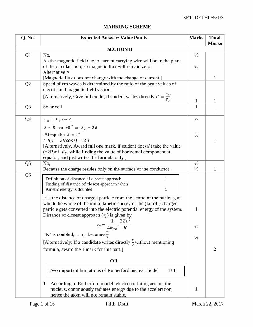
Q6
It is the distance of charged particle from the centre of the nucleus, at
which the whole of the initial kinetic energy of the (far off) charged
particle gets converted into the electric potential energy of the system.
Distance of closest approach ) is given by
‘K’ is doubled, becomes
[Alternatively: If a candidate writes directly
without mentioning
formula, award the 1 mark for this part.]
OR
1. According to Rutherford model, electron orbiting around the
nucleus, continuously radiates energy due to the acceleration;
hence the atom will not remain stable.
1
½
½
1
2
Definition of distance of closest approach 1
Finding of distance of closest approach when
Kinetic energy is doubled 1
Two important limitations of Rutherford nuclear model 1+1
SET: DELHI 55/1/3
Page 2 of 16 Fifth Draft March 22, 2017
2. As electron spirals inwards; its angular velocity and frequency change continuously; therefore it will emit a continuous spectrum.
1
2
Q7
Two objects are said to be just resolved when, in their diffraction patterns,
central maxima of one object coincides with the first minima, of the
diffraction pattern of the second object.
Limit of resolution of compound microscope
Resolving power is the reciprocal of limit of resolution
Therefore, to increase resolving power can be reduced and refractive index
can be increased.
½
½
½
½
2
Q8
(i) Communication, using waves which travel in straight line from
transmitting antenna to receiving antenna.
(ii) Because T.V. signal waves are not reflected back by the ionosphere.
1
½
½
2
Q9
=
=
½
½
½
½
2
Condition, when two objects are just resolved ½
For increasing the resolving power of a compound microscope 1 ½
(i) Definition of line of sight communication 1
(ii) Reason why it is not possible to use sky waves for transmission
of T.V. signals ½
Range of an antenna ½
Finding the ratio of de Broglie wavelength
2
SET: DELHI 55/1/3
Page 3 of 16 Fifth Draft March 22, 2017
Q10
During charging, electric flux between the plates of capacitor keeps on
changing; this results in the production of a displacement current
between the plates.
1
1
2
Q11
When a coil, carrying current, and free to rotate about a fixed axis, is
placed in a uniform magnetic field, it experiences a torque (which is
balanced by a restoring torque of suspension).
(i) To have deflection proportional to current / to maximize the
deflecting torque acting on the current carrying coil.
(ii) To make magnetic field radial / to increase the strength of
magnetic field.
Expression for current sensitivity
where is the deflection of the coil No
The galvanometer, can only detect currents but cannot measure them
as it is not calibrated. The galvanometer coil is likely to be damaged
by currents in the (mA/A) range]
OR
Self inductance of a coil equals, the magnitude of the magnetic flux,
linked with it, when a unit current flows through it.
Alternatively
Self inductance, of a coil, equals the magnitude of the emf induced in
it, when the current in the coil, is changing at a unit rate.
SI unit : henry / (weber/ampere) / (ohm second.)
1
½
½
½
½
1
½
3
Explanation of flow of current through capacitor 1
Expression for displacement current 1
Working Principle of moving coil galvanometer 1
Necessity of (i) radial magnetic field ½
(ii) cylindrical soft iron core ½
Expression for current sensitivity ½
Explanation of use of Galvanometer to measure current ½
a) Definition of self inductance and its SI unit 1 + ½
b) Derivation of expression for mutual inductance 1 ½
SET: DELHI 55/1/3
Page 4 of 16 Fifth Draft March 22, 2017
When current is passed through coil , it in turn sets up a magnetic
flux through :
But
[Note : If the student derives the correct expression, without giving the
diagram of two coaxial coils, full credit can be given]
½
½
½
3
Q12
(i) A4 : Mass Number : 172
i. Atomic Number : 69
(ii) A : Mass Number :180 i. Atomic Number : 72
[Alternatively : Give full credit if student considers decay and find atomic and mass numbers accordingly
Gives the values quoted above.
If the student takes decay
This would give the answers: (A4:172,69);(A:180,74)]
Basic nuclear process for decay
For decay
[Note: Give full credit of this part, if student writes the processes as
conversion of proton into neutron for decay and neutron into proton
for decay.]
½
½
½
½
½
½
3
Q13
Given =2kΩ
= 2 x Ω
½
(i) Determining the mass and atomic number of A4 and A ½ x 4
(ii) Basic nuclear processes of and decays ½ + ½
Calculation of collector current and input
1+1+1
SET: DELHI 55/1/3
Page 5 of 16 Fifth Draft March 22, 2017
= = 1m
current gain
Input signal voltage
= 1 x Ω
=
[Note : Give full credit if student calculates the required quantities by any
other alternative method ]
½
½
½
½
½
3
Q14
(i) Maximum kinetic energy ( of emitted electrons, depends linearly
on frequency of incident radiations
Existence of threshold frequency for the metal surface
(Any other relevant feature)
(ii) Since no photoelectric emission takes place from P it means frequency of
incident radiation ( is less than its threshold frequency .
Photo emission takes place from Q but kinetic energy of photoelectrons
is zero. This implies that frequency of incident radiation is just equal to
the threshold frequency of Q.
For Q, work function
=
= 4.125eV
½ + ½
½
½
½
½
3
Q15
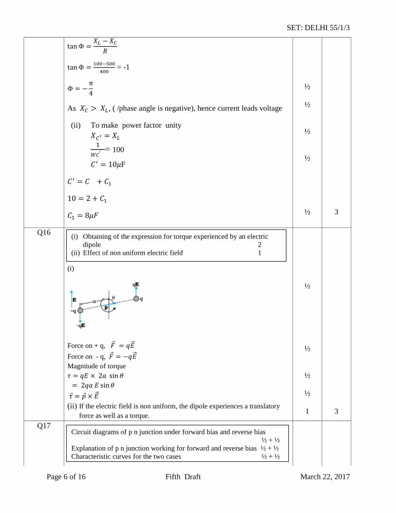
(i) =100
= 500
Phase angle
½
(i) Two important features of Einstein’s photo electric equation ½ + ½
(ii) Explanation of observations and finding value of work function of
Surface Q 1+1
(i) Calculation of phase difference between current and voltage 1
Name of quantity which leads ½
(ii) Calculation of value of ‘C’, is to be connected in parallel 1 ½
SET: DELHI 55/1/3
Page 6 of 16 Fifth Draft March 22, 2017
= -1
As , ( /phase angle is negative), hence current leads voltage
(ii) To make power factor unity
= 100
½
½
½
½
½
3
Q16
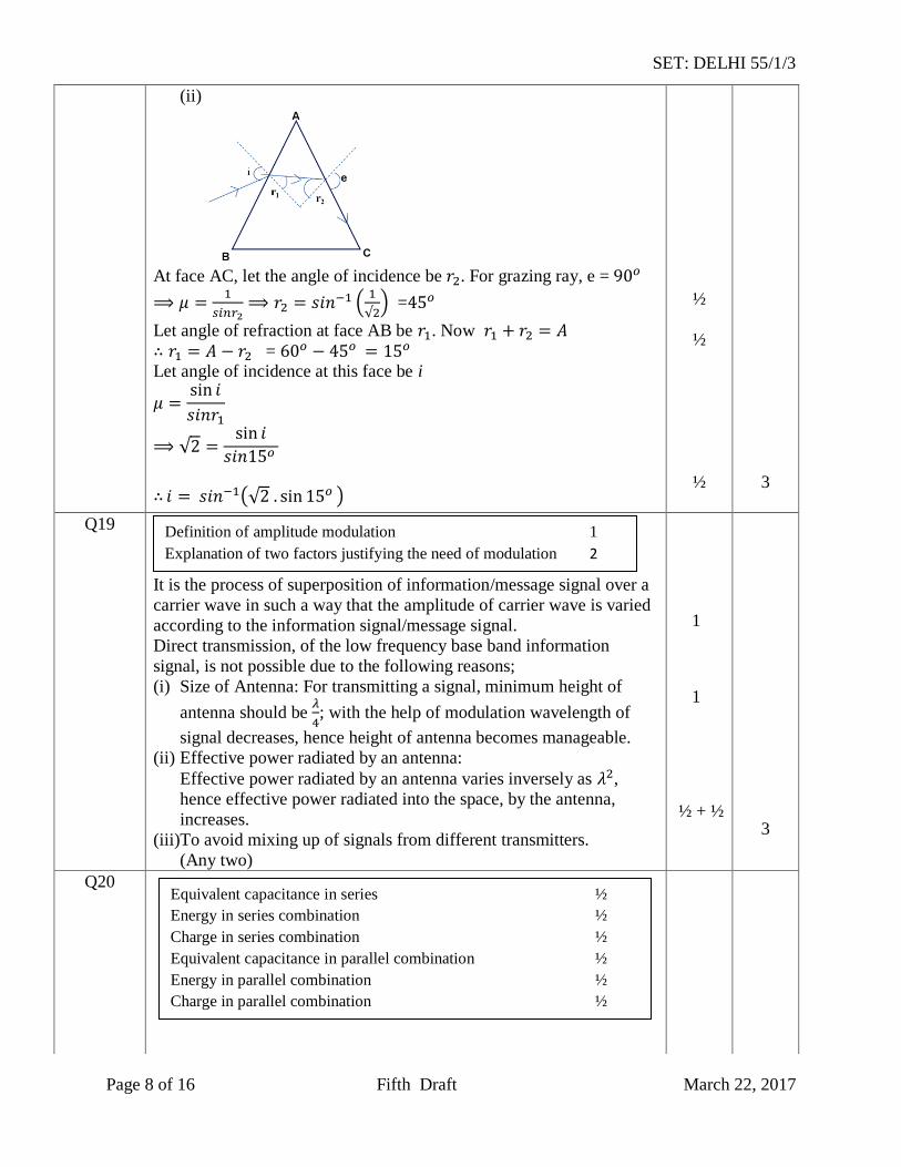
(i)
Force on + q,
Force on - q,
Magnitude of torque
(ii) If the electric field is non uniform, the dipole experiences a translatory
force as well as a torque.
½
½
½
½
1
3
Q17
(i) Obtaining of the expression for torque experienced by an electric
dipole 2
(ii) Effect of non uniform electric field 1
Circuit diagrams of p n junction under forward bias and reverse bias
½ + ½
Explanation of p n junction working for forward and reverse bias ½ + ½
Characteristic curves for the two cases ½ + ½
SET: DELHI 55/1/3
Page 7 of 16 Fifth Draft March 22, 2017
In forward bias, applied voltage does not support potential barrier. As a
result, the depletion layer width decreases and barrier height is reduced. Due
to the applied voltage, electrons from n side cross the depletion region and
reach p side. Similarly holes from p side cross the junction and reach the n
side. The motion of charged carriers, on either side, give rise to current.
In reverse bias, applied voltage support potential barrier. As a result, barrier
height is increased, depletion layer widens. This suppresses the flow of
electrons from n and holes from p . Diffusion current decreases.
The electric field direction of the junction is such that if electrons on p side
or holes on n side in their random motion comes close to the junction, they
will be swept to its majority zone. This drift of carriers give rise to the
current called reverse current.
½ + ½
½
½
½ + ½
3
Q18
(i)
=
=
Also
m/s
= 2.122
½
½
½
(i) Calculation of speed of light 1 ½
(ii) Calculation of angle of incidence at face AB 1 ½
SET: DELHI 55/1/3
Page 8 of 16 Fifth Draft March 22, 2017
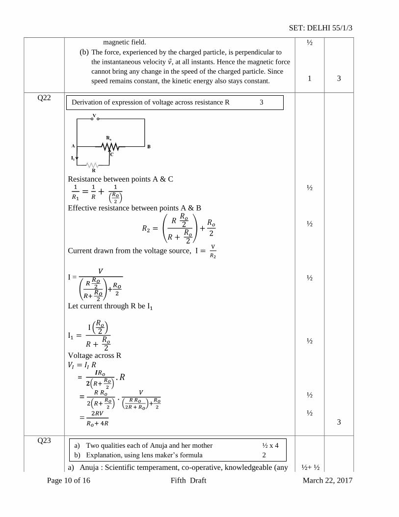
(ii)
At face AC, let the angle of incidence be . For grazing ray, e =
=
Let angle of refraction at face AB be . Now
= Let angle of incidence at this face be i
½
½
½
3
Q19
It is the process of superposition of information/message signal over a
carrier wave in such a way that the amplitude of carrier wave is varied
according to the information signal/message signal.
Direct transmission, of the low frequency base band information
signal, is not possible due to the following reasons;
(i) Size of Antenna: For transmitting a signal, minimum height of
antenna should be
; with the help of modulation wavelength of
signal decreases, hence height of antenna becomes manageable.
(ii) Effective power radiated by an antenna:
Effective power radiated by an antenna varies inversely as ,
hence effective power radiated into the space, by the antenna,
increases.
(iii)To avoid mixing up of signals from different transmitters.
(Any two)
1
1
½ + ½
3
Q20
Equivalent capacitance in series ½
Energy in series combination ½
Charge in series combination ½
Equivalent capacitance in parallel combination ½
Energy in parallel combination ½
Charge in parallel combination ½
Definition of amplitude modulation 1
Explanation of two factors justifying the need of modulation 2
SET: DELHI 55/1/3
Page 9 of 16 Fifth Draft March 22, 2017
In series combination:
J
= 6
= 300
In parallel combination:
J
= 3
C
½
½
½
½
½
½
3
Q21
(a)
(i) When velocity of charged particle and magnetic field are
perpendicular to each other.
(ii) When velocity is neither parallel nor perpendicular to the
1
½
(a) Expression for force acting on charged particle 1
(i) Condition for circular path ½
(ii) Condition for helical path ½
(b) Showing Kinetic energy is constant 1
SET: DELHI 55/1/3
Page 10 of 16 Fifth Draft March 22, 2017
magnetic field.
(b) The force, experienced by the charged particle, is perpendicular to
the instantaneous velocity , at all instants. Hence the magnetic force
cannot bring any change in the speed of the charged particle. Since
speed remains constant, the kinetic energy also stays constant.
½
1
3
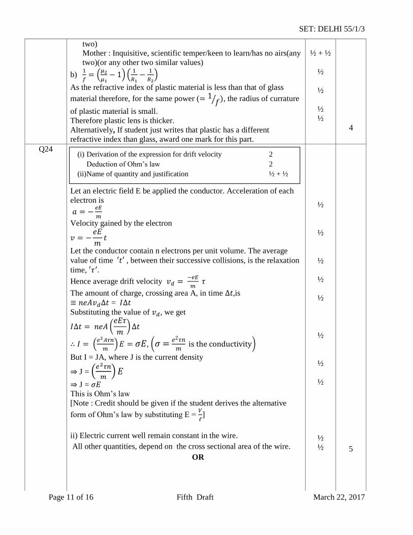
Q22
Resistance between points A & C
Effective resistance between points A & B
Current drawn from the voltage source,
I =
Let current through R be
Voltage across R
=
=
.
=
½
½
½
½
½
½
3
Q23
a) Anuja : Scientific temperament, co-operative, knowledgeable (any
½+ ½
Derivation of expression of voltage across resistance R 3
a) Two qualities each of Anuja and her mother ½ x 4
b) Explanation, using lens maker’s formula 2
SET: DELHI 55/1/3
Page 11 of 16 Fifth Draft March 22, 2017
two) Mother : Inquisitive, scientific temper/keen to learn/has no airs(any
two)(or any other two similar values)
b)
As the refractive index of plastic material is less than that of glass
material therefore, for the same power ( , the radius of currature
of plastic material is small.
Therefore plastic lens is thicker.
Alternatively, If student just writes that plastic has a different
refractive index than glass, award one mark for this part.
½ + ½
½
½
½
½
4
Q24
Let an electric field E be applied the conductor. Acceleration of each
electron is
Velocity gained by the electron
Let the conductor contain n electrons per unit volume. The average
value of time , between their successive collisions, is the relaxation
time,
Hence average drift velocity
The amount of charge, crossing area A, in time is
= Substituting the value of , we get
,
But I = JA, where J is the current density
J =
J = This is Ohm’s law
[Note : Credit should be given if the student derives the alternative
form of Ohm’s law by substituting E =
]
ii) Electric current well remain constant in the wire.
All other quantities, depend on the cross sectional area of the wire.
OR
½
½
½
½
½
½
½
½
½
½
5
(i) Derivation of the expression for drift velocity 2
Deduction of Ohm’s law 2
(ii)Name of quantity and justification ½ + ½
SET: DELHI 55/1/3
Page 12 of 16 Fifth Draft March 22, 2017
(i) Junction Rule: At any Junction, the sum of currents, entering the
junction, is equal to the sum of currents leaving the junction.
Loop Rule: The Algebraic sum, of changes in potential, around
any closed loop involving resistors and cells, in the loop is zero.
= 0
Justification: The first law is in accord with the law of conservation of
charge.
The Second law is in accord with the law of conservation of energy.
(ii) Equivalent resistance of the loop
R =
Hence current drawn from the cell
I =
=
Power consumed P = ( )
=
x =
[Note: Award the last 1 ½ marks for this part, if the calculations, for
these parts, are done by using (any other) value of equivalent
resistance obtained by the student.)
1
1
½
½
½
½
½
½
5
Q25
[Deduct ½ mark, If diagram is not labeled]
1 ½
a) Labelled diagram of AC generator 1 ½
Expression for instantaneous value of induced emf. 1 ½
b) Calculation of maximum value of current 2
(i) Statement of Kirchoff’s laws 1+1
Justification ½ + ½
(ii) Calculation of i) current drawn and 1
ii) Power consumed 1
SET: DELHI 55/1/3
Page 13 of 16 Fifth Draft March 22, 2017
When the coil is rotated with constant angular speed the angle θ between the magnetic field and area vector of the coil, at instant t, is
given by θ = t,
Therefore, magnets flux, ( ), at this instant, is
= BA cos t
Induced emf e = -N
e = NBA sin t
e= sin t
where = NBA b) Maximum value of emf
= NBA
= 20 x 200 x x 3 x x 50V
= 600 mV
Maximum induced current =
mA
[Note 1: It the student calculates the value of the maximum induced
emf and says that “ since R is not given, the value of maximum
induced current cannot be calculated”, the ½ mark, for the last part, of
the question, can be given.]
[Note 2: The direction of magnetic field has not been given. If the
student takes this direction along the axis of rotation and hence obtains
the value of induced emf and, therefore, maximum current, as zero,
award full marks for this part.]
OR
a)
Alternatively
[Note: Deduct ½ mark, if labeling is not done]
½
½
½
½
½
½
½
1 ½
5
a) Labelled diagram of a step up transformer 1 ½
Derivation of ratio of secondary and primary voltage 2
b) Calculation of number of turns in the secondary 1 ½
Soft iron core
Soft iron core
SET: DELHI 55/1/3
Page 14 of 16 Fifth Draft March 22, 2017
a) When ac voltage is applied to primary coil the resulting current produces an alternating magnetic flux, which also links the
secondary coil.
The induced emf, in the secondary coil, having turns, is
This flux, also induces an emf, called back emf, in the primary coil.
But
and
=
For an ideal transformer
=
=
b)
=
=
= 300
½
½
½
½
½
½
½
5
Q26
a) In an unpolarized light, the oscillations, of the electric field, are in
random directions, in planes perpendicular to the direction of
propagation. For a polarized light, the oscillations are aligned
along one particular direction.
Alternatively
Polarized light can be distinguished, from unpolarized light, when it is
allowed to pass through a polaroid. Polarized light does can show
change in its intensity, on passing through a Polaroid; intensity
remains same in case of unpolarized light.
When unpolarised light wave is incident on a polaroid, then the
electric vectors along the direction of its aligned molecules, get
absorbed; the electric vector, oscillating along a direction
1
1
1
a) Distinction between unpolarised and linearly polarized
light 2
Obtaining linearly polarized Light 1
b) Calculation of intensely of light 2
SET: DELHI 55/1/3
Page 15 of 16 Fifth Draft March 22, 2017
perpendicular to the aligned molecules, pass through. This light is
called linearly polarized light.
b) According to Malus’ Law:
I =
I = (
, where is the intensity of unpolarized light.
(given)
I =
=
=
OR
a)
Interference Pattern Diffraction pattern
1) All fringes are of equal width. 1) Width of central maxima is
twice the width of higher
order bands.
2) Intensity of all bright bands is
equal.
2) Intensity goes on
decreasing for higher order of
diffraction bands.
[Note: Also accept any other two correct distinguishing features.]
b) Angular width of central maximum
=
radian
= radian
Linear width of central maxima in the diffraction pattern
Let ‘n’ be the number of interference fringes which can be
accommodated in the central maxima
1
½
½
1+1
½
½
1
½
5
a) Explanation of two features (distinguishing between
interference pattern and diffraction pattern.) 2
b) Calculation of angular width of central maxima 2
Estimation of number of fringes 1
SET: DELHI 55/1/3
Page 16 of 16 Fifth Draft March 22, 2017
[Award the last ½ mark if the student writes the answers as 2 (taking