50
Stringer ePlan Manual Version 2.0 May 2019

Stringer ePlan Manual Version 2.0
May 2019

Photo credit
The photo in the front sheet has been downloaded from the following link and edited:
https://pixabay.com/en/blogging-blogger-office-business-336376/
© The State of Victoria Department of Environment, Land, Water and Planning 2019
This work is licensed under a Creative Commons Attribution 4.0 International licence. You are free to re-use the work under that licence, on the condition that you credit the State of Victoria as author. The licence does not apply to any
images, photographs or branding, including the Victorian Coat of Arms, the Victorian Government logo and the Department of Environment, Land, Water and Planning (DELWP) logo. To view a copy of this licence, visit
http://creativecommons.org/licenses/by/4.0/
Disclaimer
This publication may be of assistance to you but the State of Victoria and its employees do not guarantee that the publication is without flaw of any kind or is wholly appropriate for your particular purposes and therefore disclaims all liability for any error, loss or other
consequence which may arise from you relying on any information in this publication.
Accessibility
If you would like to receive this publication in an alternative format, please telephone the
DELWP Customer Service Centre on 136186, email [email protected],
or via the National Relay Service on 133 677 www.relayservice.com.au. This document is
also available on the internet at www.delwp.vic.gov.au.

Stringer ePlan Manual
Version 2.0
i
Stringer ePlan Manual Version 2.0
Civil Survey Solutions Pty Ltd, 1/29 Business Park Drive, Notting Hill Victoria 3168, www.civilsurveysolutions.com.au
ePlan Team, Electronic Subdivisions Unit, Department of Environment, Land, Water and Planning
Level 9, 2 Lonsdale St, Melbourne, www.spear.land.vic.gov.au
Software Development: Lead Programmer, Jon Rasmussen - AME Surveys
© Copyright – Civil Survey Solutions, Land Use Victoria
All Rights Reserved
This publication, or parts thereof, may not be reproduced in any form, by any method, for any purpose, without
the express written consent of Civil Survey Solutions Pty Ltd.
Civil Survey Solutions Pty Ltd may revise and/or improve its products (both developed and distributed by Civil
Survey Solutions Australia Pty Ltd). This publication describes the state of this product at the time of this
publication and may not reflect the product at all times in the future.
May 2019
ii Stringer ePlan Manual
Version 2.0
Contents
1. Introduction to ePlan ..............................................................................................4
2. Install Stringer ePlan ..............................................................................................5
3. Stringer ePlan Workflow .........................................................................................6
4. Getting started with ePlan ......................................................................................7
4.1 Company Setting ............................................................................................................................ 7
4.2 Project Settings .............................................................................................................................. 8
4.3 Change Jurisdiction ......................................................................................................................10
4.4 Naming Conventions for Parcels ...................................................................................................10
5. Enumerate ............................................................................................................ 12
5.1 Enumerate Parcels ........................................................................................................................12
5.1.1 Enumerate a Lot / Stage Lot .....................................................................................................12
5.1.2 Enumerate an Easement ..........................................................................................................13
5.1.3 Enumerate Road Abuttals ........................................................................................................14
5.1.4 Enumerate a Created Road ......................................................................................................15
5.1.5 Enumerate a Reserve ...............................................................................................................15
5.1.6 Enumerate Crown Parcels ........................................................................................................16
5.1.7 Enumerate a Common Property ...............................................................................................17
5.1.8 Enumerate a Restriction ...........................................................................................................17
5.1.9 Add an Address........................................................................................................................18
5.1.10 Donut Parcels .........................................................................................................................18
5.2 Enumerate Segments ....................................................................................................................20
5.3 Enumerate Points ..........................................................................................................................21
5.3.1 Boundary Points ......................................................................................................................21
5.3.2 Centroid Points ........................................................................................................................22
5.3.3 Control Marks...........................................................................................................................23
5.3.4 Reference Marks ......................................................................................................................23
5.3.5 Traverse Points ........................................................................................................................24
5.4 Enumerate Occupation ..................................................................................................................24
6. Parcel Linkages .................................................................................................... 26
6.1 Easements.....................................................................................................................................26
6.2 Multipart Parcel .............................................................................................................................27
6.3 Restrictions ...................................................................................................................................29
6.4 Owners Corporations ....................................................................................................................31
6.5 Depth Limitation ............................................................................................................................32
7. ePlan Annotation .................................................................................................. 33
7.1 Textual Annotation Types..............................................................................................................33
7.2 Referenced Annotation Types .......................................................................................................34

Stringer ePlan Manual
Version 2.0
iii
8. Review .................................................................................................................. 36
8.1 Parcel List .....................................................................................................................................36
8.2 Monument Points List ...................................................................................................................36
8.3 COGO Points List ..........................................................................................................................37
8.4 Segment List .................................................................................................................................38
8.5 Parcel Report.................................................................................................................................39
9. Export................................................................................................................... 40
10. FAQ .................................................................................................................... 44

4 Stringer ePlan Manual
Version 2.0
Introduction to ePlan
ePlan is a national initiative spearheaded by the Intergovernmental Committee on Surveying and Mapping
(ICSM) to replace the existing paper and PDF cadastral plans with a new electronic file format (ePlan). This
enables the computerisation and automation of many industry and government processes resulting in a more
efficient land administration business with higher quality of cadastral data. The ePlan implementation project
in Victoria consists of the following:
• A Victorian ePlan Protocol
• ePlan supported survey software packages
• Internal government systems to manage ePlan throughout the land administration process.
This manual provides support in creating ePlans by using the ePlan supported survey software package –
Stringer ePlan.

Stringer ePlan Manual
Version 2.0
5
Install Stringer ePlan
Stringer ePlan can be downloaded from the following link:
http://www.stringersurvey.com.au/index.php/download/#stringer-eplan
Access to the software is for 30 days without permanent licensing. To obtain a license, contact
Stringer ePlan works on the following CAD platforms:
• AutoCAD 2016, 2017, 2018 and 2019
• AutoCAD MAP 2016, 2017, 2018 and 2019
• AutoCAD Civil 3D 2016, 2017, 2018 and 2019
• BricsCAD Version 17, 18 and 19
After installing Stringer ePlan, a ribbon is added to the CAD package. In BricsCAD, a toolbar is added that
can be activated and docked in the main toolbar at the top.

6 Stringer ePlan Manual
Version 2.0
Stringer ePlan Workflow
The layout of the ePlan command interface is very logical – work from left to right on the Stringer ePlan
ribbon to easily create an ePlan file. Once you have linework in the drawing you can immediately commence
the enumeration process. The workflow is as follows:
•Company Settings - set up the company credentials
•Change Jurisdiction - the State jurisdicition
•Project Settings - define the project
Settings
•Select CAD objects to enumerate including:
•Parcels
•Points
•Segments
•Occupation
Enumerate
•Set up Parcel linkages for Parcels
•ePlan AnnotationsAnnotate
•List all the enumerated data to review and edit:
•Parcels list
•Monument points list
•COGO points list
•Segment list
•Parcel report
Review
•Export ePlan - generates an ePlan file for lodgement.
•Validate ePlan
•Create PDFExport

Stringer ePlan Manual
Version 2.0
7
Getting started with ePlan
Stringer ePlan enables attribution and enumeration of CAD drawing objects for creating ePlan to lodge
online in SPEAR at Land Use Victoria (Land Registry Services).
Stringer ePlan supports small to large scale subdivisions by enumerating CAD files. Stringer ePlan operates
in AutoCAD, AutoCAD Civil 3D, AutoCAD Map and BricsCAD and directly enumerates objects in your
drawing.
NOTE: Always keep one CAD file open in your CAD package. Otherwise the exported ePlan file might
have incorrect information.
Below is the process for enumerating the drawing.
4.1 Company Setting
In this section, you can enter and save your company data once for future use.
The Company Settings form allows you to add the name of the surveying firm and the name of the licensed
surveyor including the registration number. You can also add the name of draft person in this form and 1234
as a random number.
Click on the Company Settings icon and the following form will be displayed:
1. Click on the item you want to add
New Company
New Surveyor - Enter Surveyor Name and Number separated by a pipeline key (|) with pressing Shift+
2. Click the add new data. It will add the Company name and Surveyor name
NOTE: Make sure that the surveyor’s full name match with the registered names at Surveyors
Registration Board of Victoria (SRBV).
3. Click ‘Save and Exit’.
•Company Settings - set up the company credentials
•Change Jurisdiction - the State jurisdicition
•Project Settings - define the projectSettings

8 Stringer ePlan Manual
Version 2.0
4.2 Project Settings
Click on the Project Settings icon and the following form will be displayed:
Complete the fields as shown below:
• Survey Firm: Click on the drop-down list and select your company name that was created in the Company
Settings form
• Jurisdiction: Will be set once you click on the Stringer ePlan tool (e.g. VICTORIA).
• Plan Number: Enter plan number including check digit (e.g. PS123456A).
• Surveyor Reference: Manually add the reference required including the Version: (e.g. 123 – Ver. 2.0).
• Licensed Surveyor: Select from the drop-down list which was created in the Company Settings form the
Surveyor|Number
• Data Entry By: Select from the drop-down list
• Purpose of Survey: Click on the ‘Select’ button and select what type of survey (e.g. Plan of Subdivision)-
If you require more than one, hold Control down and add to your selection.
• Head(s) Of Power: Click on the ‘Select’ button (e.g. Subdivision Act 1988). If you require more than one,
hold Control down and add to your selection.
• Survey Format: Select from the drop-down list (e.g. Level Land)
• Survey Type: Select from the drop-down list (e.g. surveyed)
– Survey Type refers to whether the plan is based on survey, non-survey or partial survey. ePlan uses
slightly different terminology as follows:
Stringer ePlan Manual
Version 2.0
9
Surveyed = Survey
Computed = Non-survey
Compiled = Partial-survey
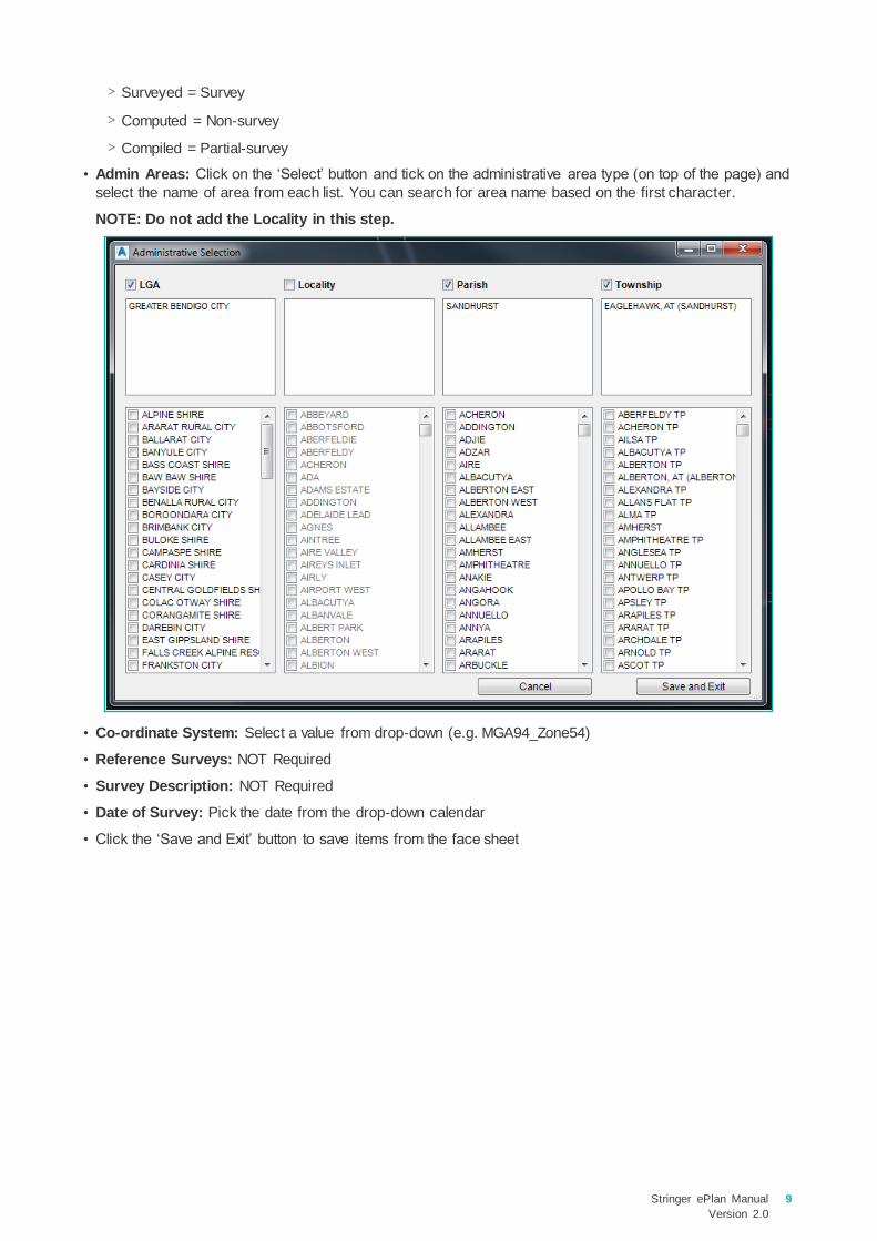
• Admin Areas: Click on the ‘Select’ button and tick on the administrative area type (on top of the page) and
select the name of area from each list. You can search for area name based on the first character.
NOTE: Do not add the Locality in this step.
• Co-ordinate System: Select a value from drop-down (e.g. MGA94_Zone54)
• Reference Surveys: NOT Required
• Survey Description: NOT Required
• Date of Survey: Pick the date from the drop-down calendar
• Click the ‘Save and Exit’ button to save items from the face sheet

10 Stringer ePlan Manual
Version 2.0
4.3 Change Jurisdiction
Click on change Jurisdiction icon and select from the list below. For a Victorian plan, select ‘Victoria’.
4.4 Naming Conventions for Parcels
ePlan uses a standardised element identification system based on the Victorian Standard Parcel Identifier
system. Every interest type has a specific identifier format that must be used when creating new interests on
a plan as follows:
[Parcel ID] \ [Plan Number]
For example, Lot 1 on plan PS123456 is represented as 1\PS123456.
The table below illustrates the naming convention for parcels in ePlan.
'#' represents a number and '%' represents a numeric or alphabet character.
Parcel Class Format Example
Lot
* Balance Lot
* Consolidated Lot
[#] \ [Plan Number]
[%] \ [Plan Number]
[#] [%] \ [Plan Number]
[%] [#] \ [Plan Number]
NOTE – A, E, R and S are not
acceptable when % is followed by a
number (e.g. A1)
BL [#] \ [Plan Number]
[Plan Number starting with PC/CP]
1\PS123456
A\PS123456, AA\PS123456
1A\PS123456
G101\PS123456
BL1\PS123456
PC123456
Common property CM [#] \ [Plan Number] CM1\PS123456
Reserve
* Reserve Abuttal (@state=”existing”)
RES [#] \ [Plan Number]
RESERVE – [#]
RES1\PS123456
RESERVE-1
Road and Road Abuttal
Road (@state=”created”)
* Road Abuttal (@state=”existing”)
R [#] \ [Plan Number]
ROAD – [#]
R1\PS123456
ROAD-1

Stringer ePlan Manual
Version 2.0
11
Parcel Class Format Example
Easement (@parcelFormat="Standard" /
"2D Building")
* Encumbering Easement (@parcelFormat="Geometry")
* Appurtenant Easement (@parcelFormat="Geometry")
* Encumbering Easement (Road)
(@parcelFormat="Geometry")
EAS [#] \ [Plan Number]
E [#]
A [#]
R [#]
EAS1\PS123456
E1
A1
R1
Restriction RST [#] \ [Plan Number] RST1\PS123456
Owners Corporation OC [#] \ [Plan Number] OC1\PS123456
Stage Lot S [#] \ [Plan Number] S1\PS123456
Depth Limitation DL [#] DL1
Crown Parcel
Crown Allotment [Allotment %] ~ [Section %] \ PP
[Parish or Township Code]
If there is no Crown Section,
[Allotment %] \ PP [Parish or
Township Code]
31~2\PP5509
31\PP5509
Crown Portion
[Portion %] \ PP [Parish or Township
Code]
1\PP4568
Parcels without SPI NOSPI – [#] NOSPI-1
Not in Subdivision NIS – [#] NIS-1
Administrative Area Parcels – Code
is the Land Use Victoria official
identifier, as stored in Vicmap Admin
LGA LGA – [VMADMIN Code] LGA-301
Parish PSH – [VMADMIN Code] PSH-355
Township TWN – [VMADMIN Code] TWN-23
Part Parcels (@parcelType="Part")
Exception for Part Geometry Easements (@parcelType="Part"
& @parcelFormat="Geometry"
& @class="Easement")
and Part Existing Road (@parcelType="Part" &
@state="existing" &
@class="Road")
[Prefix] [#] – p [#] \ [Plan Number]
1-p1\PS123456
E1-p2
Road-1-p2
NOTE: Parcel identifier can have the check digit following the plan number e.g. "1\PS123456X".
NOTE: If there is no plan number at the time of ePlan submission for Section 23, 24A, 32 or 32B
applications of the Subdivision Act 1988, the term ‘LV-To-Supply’ must be used instead. This value
will be replaced in ePlan with a Dealing Number from the Victorian Online Title System (VOTS) after
the plan is registered at Land Use Victoria.
NOTE: If there is no SPI for a parcel then name it as ‘NOSPI – [#]’ e.g. NOSPI-1. These parcels must
have a description.
NOTE: Special Parcel Usages – Special usages of Parcel element, doesn’t represent an actual parcel
type.

12 Stringer ePlan Manual
Version 2.0
Enumerate
5.1 Enumerate Parcels
After completing the first step, you can now enumerate objects in your drawing.
To create a parcel in Stringer ePlan use the Enumerate Parcel Tool. This tool is used for open and closed
polylines to create parcels.
NOTE: Lines cannot be enumerated. Lines need to be converted into polylines. Use the command
’PE’ to convert a line to a polyline. Closed polylines can also be created using BPOLY.
• Click on the Enumerate Parcels icon
• Click on a polyline
• The Enumerate Parcels Window will pop up
There is some information in the Enumerate Parcels Window as shown below:
• Assigned: The Assigned Bearing and Distance is assigned by the user, which can be different from the
calculated ones. For example, you may need to adopt a dimension based on the title which might be
different from the calculated one. The assigned values will overwrite the calculated ones and will be
exported to ePlan LandXML.
• Area: is the actual area from the linework
• REG Area: This is the area you would like to assign to this parcel and export it in ePlan
• Action: Select a state such as created, existing, extinguished for the parcel from the drop-down list
• Parcel Intent: This drop-down is used to define various parcel types such as Lot, Easement, Common
Property
• Parcel Type: This drop-down is used to define Parcel type. It can be Single, Part, Multipart or
Administrative
• Parcel Format: This drop-down is used to define Parcel Format. This can be Standard, Geometry for
Easements, or 2D Building for Lots including building boundaries.
• Add Links: This is used for defining Restrictions (See section 6 for defining Restrictions)
• Description: This filed adds a description to a Parcel (for example, Road name or description for a
Restriction, or a TP reference for extinguished Crown Allotments)
NOTE: Once you have enumerated the parcel, click ‘Save and Exit’. This will add a Centroid Point to
the drawing and add the Parcel Number and Area text to the parcel you just enumerated. If you need
to edit the parcel, click on the Parcel Number and name text and the window will pop up.
For all parcel types look at the naming convention in section 4.4 to enter a correct name in the forms.
5.1.1 Enumerate a Lot / Stage Lot
Enter the name of the Parcel in the box top left: (e.g. 1:PS716856).
•Select CAD objects to enumerate including:
•Parcels
•Points
•Segments
•Occupation
Enumerate

Stringer ePlan Manual
Version 2.0
13
• Select ‘extinguished’ for Action in the dropdown for cancelled Parcels. NOTE: This is the Lot identifier
for the last plan reference for Extinguished Lots. Select ‘created’, ‘existing’, etc. for other types of
parcels.
• Parcel Intent: Lot / Stage Lot
• Parcel Type: Single, Part or 2D Building (where at least one boundary line is a building boundary in
drawing)
• Parcel format: (e.g. Standard). NOTE: Lots including building boundary must have ‘2D Building’ for
Parcel Format.
• For Extinguished Parcels you need to provide Volume and Folio (Vol/Fol) and select the Title Type. Type
the Vol/Fol in at the top (e.g. 10790/065) and select Freehold, etc. as Title Type. In addition, you need to
add address to the extinguished and affected Parcels in a Plan of Subdivision as well as existing Parcels in
a Boundary Plan (See Section 5.1.9).
NOTE: To enumerate many lots in multi-lot subdivisions, click on , then select the parcels by
drawing a line through the parcels (enter ‘F’, and draw a line to select the parcels). Press enter and
fill out the required attributes, then Save and Exit. It automatically pops up a window for all selected
parcels for checking and enumerating them. From Stringer version 19.01, parcel name is filled out
automatically and for the subsequent parcels, the parcel number will be incremented by 1 and
assigned to parcel name. If you change the values, it keeps them for the next parcels.
5.1.2 Enumerate an Easement
Creating an Easement is like creating a Lot. However, you need to assign correct attributes as shown below:
• Parcel Name: E1, A1, R1 (correct naming convention for Easements according to Section 4.4)
NOTE: Parcel name for a part Easement is E1-p1.
NOTE: Dash character like E-1 is not accepted for naming Easements.
• Action: Created, etc.
• Parcel Intent: Easement
• Parcel Type: Single or Part (for defining the Easement parts as part of multipart Easements)
• Parcel Format: Geometry

14 Stringer ePlan Manual
Version 2.0
Click the ‘Save and Exit’ button.
Go to Section 6.1 to add required attributes to the Easement.
5.1.3 Enumerate Road Abuttals
The Road is enumerated as a Parcel from a polyline drawn where the road is. NOTE: This is an open
polyline which is converted to a parcel.
The ROAD is enumerated as below:
• Name: For existing Road you need to use ROAD-# (e.g. ROAD-2)
• Description: This is the name of the road (e.g. BEAUFORT ROAD)
• REG Area: 0
• Action: Existing
• Parcel Intent: Road
• Parcel Type: Single or Part (for defining the Road parts as part of multipart Roads)
• Parcel Format: Standard
Once you have completed all details click on the ‘Save and Exit’ button.
NOTE: Once you have added the centroid to the Road Parcel, you can move that centroid point to a
preferred position for showing the Road name in the PDF Plan.

Stringer ePlan Manual
Version 2.0
15
5.1.4 Enumerate a Created Road
The created Road is enumerated as a parcel from a closed polyline drawn where the road is.
The ROAD is enumerated as below:
• Name: For created Road you need to use R [#] \ [Plan Number] (e.g. R2\PS123456)
• Description: This is the name of the road (e.g. BEAUFORT ROAD)
• REG Area: (e.g. 200)
• Action: Created
• Parcel Intent: Road
• Parcel Type: Single or Part (for defining the Road parts as part of multipart Roads)
• Parcel Format: Standard or 2D Building (where at least one boundary line is a building boundary in
drawing)
• Parcel Owner: A Parcel Owner is required (e.g. City of Melbourne)
Once you have completed all details click on the ‘Save and Exit’ button.
NOTE: Multipart created Roads can be also created in ePlan. In this case, each part is created using a
name based on the parcel naming convention in Section 4.4 (e.g. R1-p1\PS123456). The multipart
parcel itself (R1\PS123456) should be created in Parcel Linkages window according to Section 6.2.
5.1.5 Enumerate a Reserve
The Reserve is enumerated as a parcel from an open or closed polyline drawn where the reserve is.
The Reserve is enumerated as below:
• Name: For Reserve you need to use RES [#] \ [Plan Number] (e.g. RES2\PS123456).
• Description: Name of the reserve (e.g. BEAUFORT)
• REG Area: 200
• Action: created
• Parcel Intent: Reserve

16 Stringer ePlan Manual
Version 2.0
• Parcel Type: Single or Part (for defining the Reserve parts as part of multipart Reserves)
• Parcel Format: Standard or 2D Building (where at least one boundary line is a building boundary in
drawing)
• Parcel Owner: A Parcel Owner is required
NOTE: Existing closed Reserve requires an address.
5.1.6 Enumerate Crown Parcels
Crown Parcels are captured using the Enumerate Parcel form. Name of the Crown Parcel must be correctly
defined in the Parcel name according to the Naming Convention for Parcels.
NOTE: If the Crown parcel is an extinguished (cancelled) parcel, then the name of the Crown parcel
would be placed in PDF as Last Plan Reference. To replace this value with the correct plan reference,
enter the expected plan reference in ‘Description’ to be displayed as Last Plan Reference (e.g.
1\TP123456) in PDF.

Stringer ePlan Manual
Version 2.0
17
5.1.7 Enumerate a Common Property
Common Property is created as a parcel using the Enumerate Parcel form.
NOTE: If you would like to add a road name to the Common Property, add it to the Description.
5.1.8 Enumerate a Restriction
There are two main types of Restrictions:
1. Spatial Restrictions
2. Non-Spatial Restrictions
To create a spatial Restriction, you need to create a parcel for the affected area. See Section 4.4 for the
naming convention for a created Restriction. Spatial restrictions should be fixed to lot boundaries using a
connection such as a Topo line or an offset (See Section 5.4). For Restriction enumeration see Section 6.3.
Non-spatial restrictions can be defined without any geometry. See Section 6.3.

18 Stringer ePlan Manual
Version 2.0
5.1.9 Add an Address
Click on ‘Add Address’ and include the information.
• Click on the ‘Add’ button, bottom left
• Tick on ‘Administrative Area & Road Name’ at the top
• Complete the Administrative Area fields
• Admin Area Type: Select ‘Locality’ from the drop-down list
NOTE: The only accepted value for this item is ‘Locality’
• Admin Area Name: Select a value from drop-down list (e.g. Skipton)
• Post Code: e.g. 3361
Complete the Road Name
• Road Name: e.g. Blake
• Road Name Type: Select a value from the drop-down list (e.g. Street)
• Road Name Suffix: Select a value from the drop-down list (e.g. None)
• Road Type: Select a value from the drop-down list (e.g. Public). NOTE: For private roads, select
‘private’.
• Parcel Reference: None
• Address Type: Select a value from the drop-down list (e.g. Primary)
• Number First: e.g. 41
• Number Last: e.g. 45
Click the ‘Save and Exit’ button to add the address to this parcel.
NOTE: If you DON’T want the address to be added to the parcel then click ‘QUIT’. If you have already
given a parcel an address and no longer need it, click on the address in the parcel and then click
‘QUIT’. The address will be removed from that parcel. You don’t need to add an address for created
Lots, unless required.
5.1.10 Donut Parcels
ePlan supports all types of donut parcels including nested donuts (donuts within donuts). Donut parcels
consist of polygons with internal holes. These are captured in Stringer ePlan as a single continuous simple
polyline beginning and ending on the outer ring of the donut. To connect the inner rings of the donut, double
lines need to be drawn (see diagram below). One line, traces into the inner rings and the other line traces
out. The connecting lines must be the normal boundary. It should be noted that the direction of inner rings
reverses with each level of internal ring. If the outer ring is clockwise, then the first level internal ring will be
Stringer ePlan Manual
Version 2.0
19
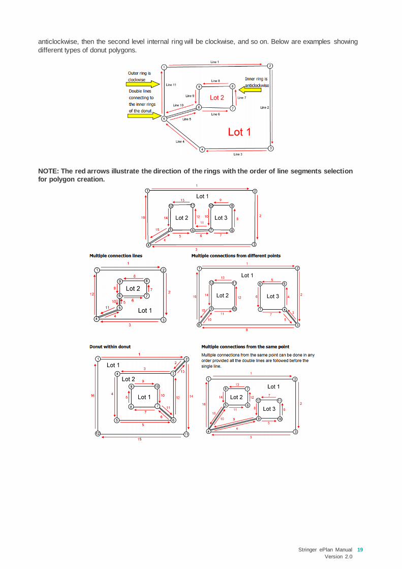
anticlockwise, then the second level internal ring will be clockwise, and so on. Below are examples showing
different types of donut polygons.
NOTE: The red arrows illustrate the direction of the rings with the order of line segments selection
for polygon creation.

20 Stringer ePlan Manual
Version 2.0
5.2 Enumerate Segments
In ePlan, traverse lines, radiations, topo lines and building boundaries need to be enumerated by using the
Enumerate Segments function.
• Click on the Enumerate Segment icon and select the line you want to enumerate.
• Click on the traverse, topo, radiation or building boundary lines
• Purpose: Select what is required – (e.g. traverse)
• Upload: Make sure it is ticked on if you want it to be added to the XML
• Click ‘Save & Exit’
To define building boundaries (median, interior face, exterior face, or other) enumerate them by assigning a
Physical Boundary Description. See below example for selecting the correct value:
NOTE: To assign different values to the computed bearings and distances, enter the required values
in the Assigned Textbox. The visualiser will show the values entered to the text boxes. In addition, if
you need to show the adopted dimensions underlined in PDF, change the Measured value in the
drop-down to Adopt Dimension.

Stringer ePlan Manual
Version 2.0
21
To Enumerate an Arc:
• Click on the Enumerate Segment icon and select the arc you want to enumerate.
• Click on the topo or building boundary arcs
• Purpose: Select what is required – (e.g. topo)
• Upload: Make sure it is ticked on if you want it to be added to the XML
• Click ‘Save & Exit’
NOTE: You can assign different values to Bearing, Chord (Distance), Radius and Arc Length.
5.3 Enumerate Points
5.3.1 Boundary Points
Once parcels are enumerated, points are automatically added to their corners. Once added to the parcel,
they have a default setting on Parcel Points as following:
• Mark Name: Next available
• Survey Point Type: Boundary
• State: Proposed

22 Stringer ePlan Manual
Version 2.0
5.3.2 Centroid Points
The centroid point and centre of the arcs are also automatically added to the drawing and their default values
are:
• Mark Name: Next available
• Survey Point Type: Sideshot
• State: Proposed
Road Abuttals also add points:
• Mark Name: Next available
• Survey Point Type: Sideshot
• State: Proposed

Stringer ePlan Manual
Version 2.0
23
5.3.3 Control Marks
In ePlan, pursuant to the Surveying Regulations 2015, there must be at least three PMs or PCMs connected
to the survey for up to and including 10 Parcels. If there are more than 10 Parcels, further PMs or PCMs
must be placed within the subdivision so that the distance between these marks is not greater than 100
metres.
To enumerate Control Marks, complete the following attributes:
• Mark Name: Next available (Can't be the same number and must be unique)
• Description: e.g. GPSNET SKIPTON
• Survey Point Type: Control
• State: e.g. Existing
Tick the Plan Monument box
• Monument Type: e.g. Plaque
• State: e.g. Existing
• Condition: e.g. OK
Tick the Horizontal Monument box
• Datum: e.g. MGA94_Zone54
• Order: e.g. 3
• Fix: e.g. Adjustment
• Identification Number (oID): Nine figure number e.g. 348901330
• Current Date: e.g. 2016-05-20
NOTE: In ePlan, distances are based on the ground observation and scale factor is not applied. When
including the Control Marks in your drawing, consider one of those as a base point with True MGA
coordinates and use bearing and distance to connect all your marks together. If you have GNSS
control points in your drawing, you need to convert the MGA coordinates into local coordinates and
connect the control marks by bearings and ground distances.
5.3.4 Reference Marks
Reference marks are enumerated as Reference points in Stringer ePlan. To define them as monuments, you
need to tick ‘Plan Monument’ and assign attributes as Monument Type, State and Condition.
24 Stringer ePlan Manual
Version 2.0
5.3.5 Traverse Points
Traverse points are automatically created when you enumerate a segment as a traverse line. However, to
create a traverse point, assign ‘traverse’ for the Survey Point Type and ’existing’ for State. There is no need
to assign other attributes to traverse points.
5.4 Enumerate Occupation
The Enumerate Occupation function in Stringer ePlan adds different occupation types (Plan Features) to the
diagram. The examples of plan and survey documents that require ePlan Occupation are Plans of
Subdivision (containing a building return), survey-based Transfer of Land Act applications, Re-establishment
surveys and Abstract of Field Records.
The following Occupation types have been considered in the Victorian ePlan:
• Building Return (hatched walls on Plan of Subdivision)
• Masonry Wall (to cover brick walls, buildings, etc.)
• Timber Wall
• Fence
• Offset (to show an offset for restriction diagrams on Plan of Subdivision)
• Chainage
• Kerb
• Gate
• Centreline
• No symbol (e.g. Not Fenced, Not Defined, etc.)
• Railway
• Rockwall
• Hedge
• Other (e.g. verandah, roller door, etc.)
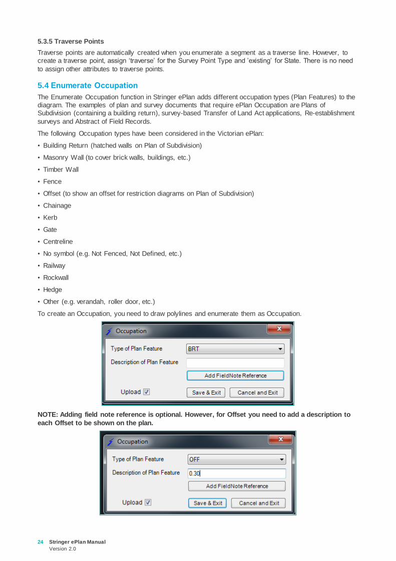
To create an Occupation, you need to draw polylines and enumerate them as Occupation.
NOTE: Adding field note reference is optional. However, for Offset you need to add a description to
each Offset to be shown on the plan.

Stringer ePlan Manual
Version 2.0
25
To enumerate a chainage, pick the polyline and add a description for the chainage. The length of the
chainage is calculated by the software.

26 Stringer ePlan Manual
Version 2.0
Parcel Linkages
The Parcel Linkages tool is used for defining non-spatial parcels. For example, an Easement, Restriction, or
Owners Corporation, can be defined using this tool. Moreover, this tool should be used for creating multipart
parcels and assigning geometry parts to them.
Click the icon and complete the required fields.
6.1 Easements
Easements in ePlan are captured using a slightly different method to paper plans. In ePlan, a polygon
(Geometry Easement (e.g. E1)) is created in the diagram for each easement area, the polygon is then
assigned to the easement interest(s) (e.g. EAS1).
If the geometry easement comes in parts, then the multipart geometry parcel needs to be created in Parcel
Linkages first and then it should be assigned to the easement interest (e.g. EAS1). If there are multiple
interests over the same easement area, the polygon is not duplicated and will be simply assigned to all
relevant interests.
Complete the following three steps to create an easement:
1. An individual polygon should be drawn on the diagram to include the geometry of each Easement, as
easements are currently shown on PDF Plans (see figure below).
NOTE: You do not need to draw the overlapping easement polygons. The overlapping easements will
be identified and visualised automatically by the ePlan visualiser. However, if the automatic naming
of the overlapping easements does not suit you, alternatively create a geometry easement and
enumerate it for the overlapping area(s) with your desired name.
On the diagram, the easements should have a name of ‘E#’ (for encumbering Easement), ‘A#’ (for
appurtenant Easement) or ‘R#’ (for encumbering Easement (road)). Part Easements should have a
description of ‘E#-p#’, ‘A#-p#’, or R#-p#. No origin should be included within the name of easements drawn
on the diagram.
NOTE: For any Encumbering Easement (Road), there must be one created Road in the diagram with
the same geometry and name (‘R#’).
2. For each unique combination of purpose/origin/beneficiary, a Standard/2D Building Easement should be
created within the Parcel Linkages Tool. The Standard/2D Building Easement should include the
•Set up Parcel linkages for Parcels
•ePlan AnnotationsAnnotate

Stringer ePlan Manual
Version 2.0
27
reference(s) to the geometry segment(s) created in step 1 and some information about that Easement
(e.g. purpose, origin, beneficiary).
3. If you need to have an Easement Width, add an Annotation (Easement Width) in ePlan Annotations
and connect it back to the Geometry Easement (E#).
4. If you need to replace the Purpose or Origin of easement with the user-defined text in front sheet, add an
annotation (Easement Purpose or Easement Origin) in ePlan Annotations and connect it back to the
Non-spatial Easement (EAS#).
For an Easement, the following attributes are required in the Parcel Linkages to connect the geometry
Easement to the required attributes:
• Name: e.g. EAS1\PS123456
• Action: e.g. created
• Parcel Intent: Easement
• Parcel Type: e.g. Single
• Parcel Owner: e.g. CORANGAMITE SHIRE COUNCIL
• Parcel Use: e.g. Drainage
• Parcel Format: e.g. Standard
• Upload: Ticked
To link the geometry Parcels to this non-spatial Parcel, tick on ‘Has Linkages’ and select the Parcel
Reference from the drop-down list and click ‘Save Changes’. To link more geometries, click on add ‘New
Association’:
• Parcel Reference: e.g. E1 (from drop-down list)
• Click ‘Save Changes’ (if not, any changes made will not be saved)
6.2 Multipart Parcel
A Multipart Parcel is a parcel that consists of multiple closed or unclosed polylines. It is represented using a
parent ‘Multipart" parcel linked to 2 or more children ‘part’ parcels.
28 Stringer ePlan Manual
Version 2.0
Part Parcels have a different naming convention to regular parcels to ensure they are unique in the file:
[Prefix] [#] – p [#] \ [Plan Number] e.g. 1-p1\PS123456
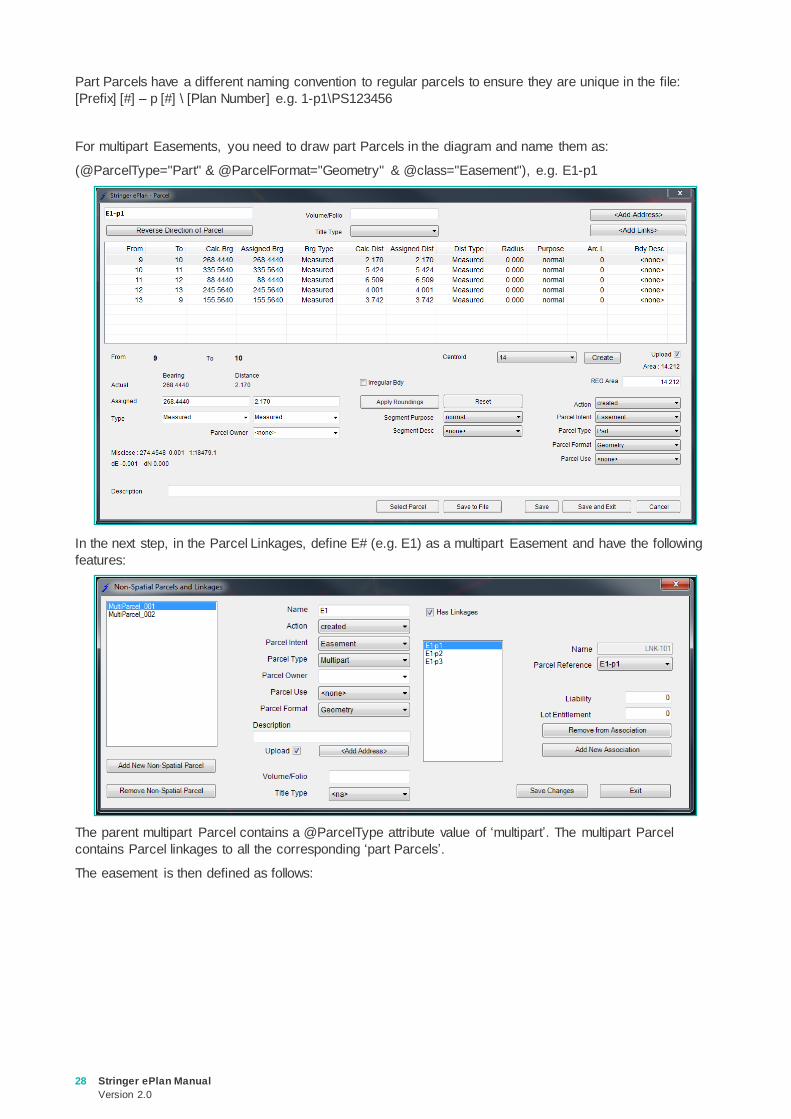
For multipart Easements, you need to draw part Parcels in the diagram and name them as:
(@ParcelType="Part" & @ParcelFormat="Geometry" & @class="Easement"), e.g. E1-p1
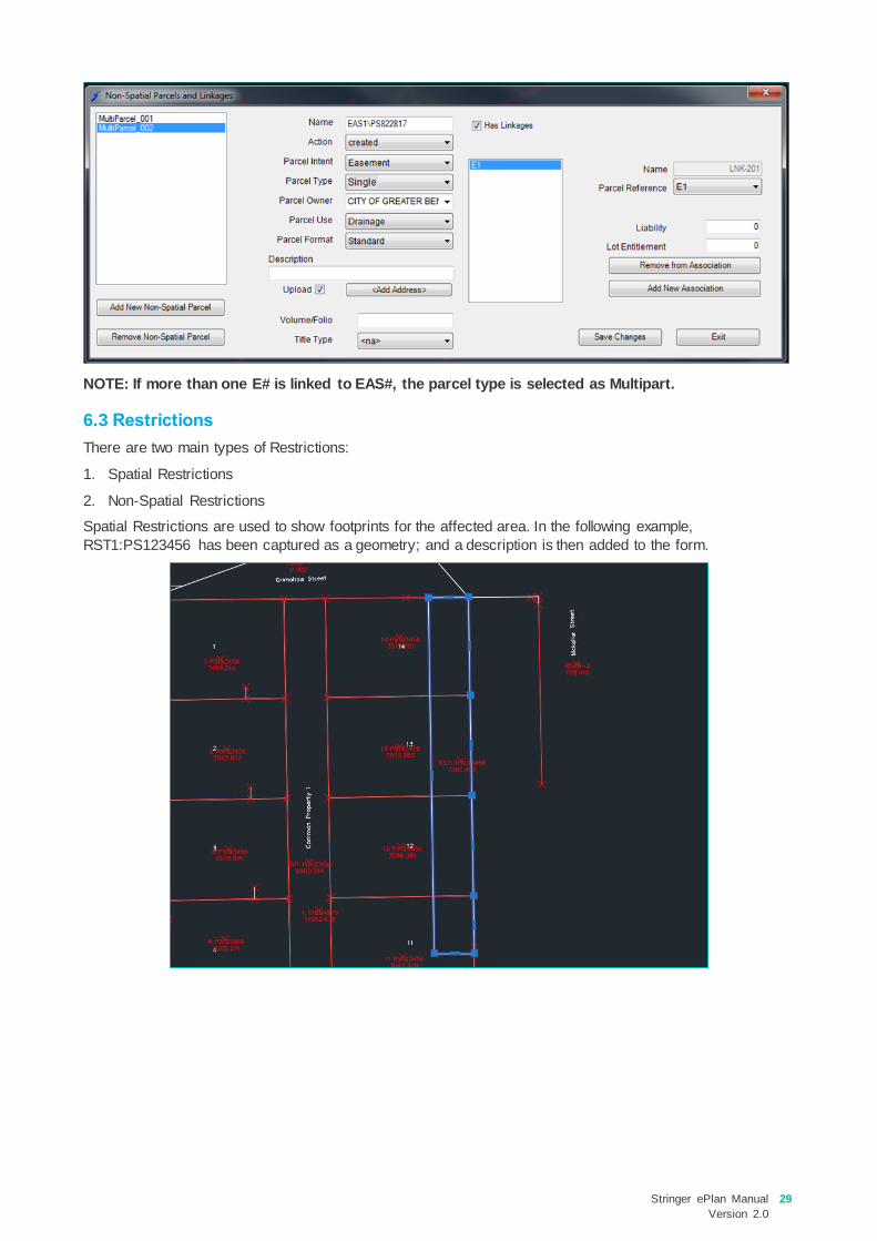
In the next step, in the Parcel Linkages, define E# (e.g. E1) as a multipart Easement and have the following
features:
The parent multipart Parcel contains a @ParcelType attribute value of ‘multipart’. The multipart Parcel
contains Parcel linkages to all the corresponding ‘part Parcels’.
The easement is then defined as follows:
Stringer ePlan Manual
Version 2.0
29
NOTE: If more than one E# is linked to EAS#, the parcel type is selected as Multipart.
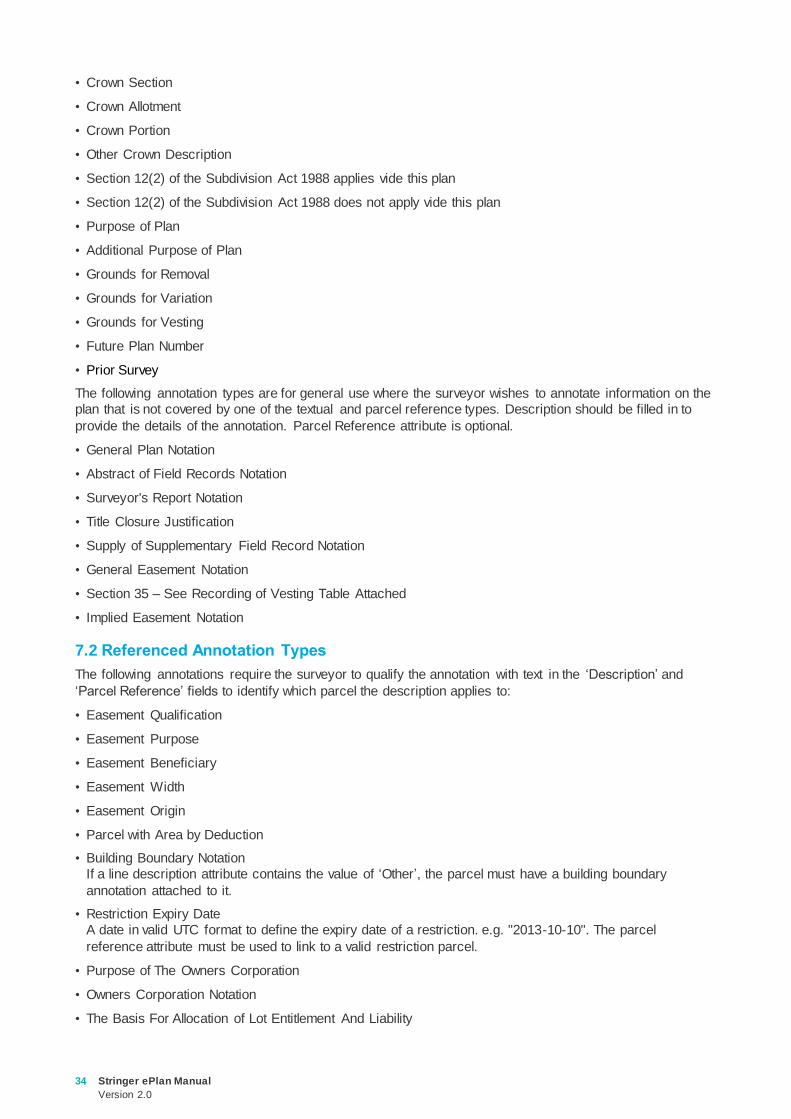
6.3 Restrictions
There are two main types of Restrictions:
1. Spatial Restrictions
2. Non-Spatial Restrictions
Spatial Restrictions are used to show footprints for the affected area. In the following example,
RST1:PS123456 has been captured as a geometry; and a description is then added to the form.

30 Stringer ePlan Manual
Version 2.0
Finally, benefited and burdened Lots need to be defined using <Add Links> in Enumerate Parcel form, which
links those parcels to the Restriction.
NOTE: To add the expiry date, you need to add an annotation with type ‘Restriction Expiry Date’.
Non-spatial Restrictions are defined without any geometry in the Parcel Linkages. Then, similar to the above-
mentioned step, the benefited ad burdened parcels must be linked to the Restriction using <Add Links>.

Stringer ePlan Manual
Version 2.0
31
NOTE: According to Land Use Victoria’s policies, if Restriction diagram and table do not fit in one
page then it is strongly recommended to define Restriction(s) in MCP and put the MCP number on
the front sheet.
6.4 Owners Corporations
The Owners Corporation (OC) entity must first be created in Parcel Linkages. The following attributes are
required:
• The naming convention for an OC is ‘OC#\Plan Number’, e.g. ‘OC1\PS123456’.
NOTE: Do not use spaces or symbols.
• Description: Free text
• State: e.g. created
• Type: Single
• There are 3 OC usages in the Parcel Use drop-down list - ‘Unlimited’, ‘Limited’ and ‘Limited to Common
Property’.
• Format: is always ‘Standard’
NOTE: An address must be assigned to each Owners Corporation using “<Add Address>” in the
Parcel Linkages window.
The last step is to assign the entitlement and liability values to the member Lots. Click on ‘Add New
Association’, select each parcel and set the values in the form. The Common Property Parcel must have its
values set to ‘0’. Some annotations are required for OC (see ePlan Annotations).

32 Stringer ePlan Manual
Version 2.0
6.5 Depth Limitation
Depth Limitation Parcels naming convention is: DL[#]. For example, a Depth Limitation is represented as
‘DL1’. To create a non-spatial Depth Limitation, use the Parcel Linkages tool.
NOTE: It is not required to link the Depth Limitation to affected parcels. You can enter any text
including affected parcels in “Description”.

Stringer ePlan Manual
Version 2.0
33
ePlan Annotation
The Annotation element is used to capture various pieces of textual information.
Click the ePlan Annotations icon to enter the annotations to your plan. The annotations are mainly
for the benefit of future surveyors, examiners and auditors, where additional textual information about the
plan may be required for specific situations. The requirements for each field differ depending on the
annotation.
NOTE: Save changes after adding each annotation before adding another annotation.
Click ‘Add New’ to add a row for a new annotation. Select a type and add a text for the annotation as a
description.
NOTE: Some annotations require a Parcel Reference e.g. Easement Width. They are listed in the
below sections.
For an overview of all the annotations added to this form, click on the ‘Summary of Annotations’ button and
all added data for the ePlan Annotations will be shown as below:
7.1 Textual Annotation Types
The following annotations require the surveyor to qualify the annotation with text in the description field. The
following types do not require a ‘Parcel Reference’:
• Planning Permit
• Report on Datum
• Instrument and Calibration Details
34 Stringer ePlan Manual
Version 2.0
• Crown Section
• Crown Allotment
• Crown Portion
• Other Crown Description
• Section 12(2) of the Subdivision Act 1988 applies vide this plan
• Section 12(2) of the Subdivision Act 1988 does not apply vide this plan
• Purpose of Plan
• Additional Purpose of Plan
• Grounds for Removal
• Grounds for Variation
• Grounds for Vesting
• Future Plan Number
• Prior Survey
The following annotation types are for general use where the surveyor wishes to annotate information on the
plan that is not covered by one of the textual and parcel reference types. Description should be filled in to
provide the details of the annotation. Parcel Reference attribute is optional.
• General Plan Notation
• Abstract of Field Records Notation
• Surveyor's Report Notation
• Title Closure Justification
• Supply of Supplementary Field Record Notation
• General Easement Notation
• Section 35 – See Recording of Vesting Table Attached
• Implied Easement Notation
7.2 Referenced Annotation Types
The following annotations require the surveyor to qualify the annotation with text in the ‘Description’ and
‘Parcel Reference’ fields to identify which parcel the description applies to:
• Easement Qualification
• Easement Purpose
• Easement Beneficiary
• Easement Width
• Easement Origin
• Parcel with Area by Deduction
• Building Boundary Notation
If a line description attribute contains the value of ‘Other’, the parcel must have a building boundary
annotation attached to it.
• Restriction Expiry Date
A date in valid UTC format to define the expiry date of a restriction. e.g. "2013-10-10". The parcel
reference attribute must be used to link to a valid restriction parcel.
• Purpose of The Owners Corporation
• Owners Corporation Notation
• The Basis For Allocation of Lot Entitlement And Liability

Stringer ePlan Manual
Version 2.0
35
• Details Of The Limitations of The Owners Corporation
• Functions or Obligations Referred By The Limited Owners Corporation
• Functions or Obligations Referred To The Unlimited Owners Corporation
• Section 35 Compulsory
• Section 35 Agreement
• Balance Of Existing OC Entitlement
• Balance Of Existing OC Liability
NOTE: Annotations can be accompanied by a Description and Parcel References. A Description is
always required for all annotations. Description field must not be blank. For example, ‘Parcel with
Area by Deduction’ requires no further description so copy the ‘Type’ text into the Description box.
NOTE: ‘Easement Width’ annotation must be only linked to Geometry Easements drawn on the
diagram (specified as ‘E#’, ‘A#’ or ‘R#’) and not the Standard/2D Building Easements created in the
Parcel Linkages (specified as ‘EAS#’).
NOTE: ‘Implied Easement Notation’, ‘Easement Purpose’, ‘Easement Origin’ and ‘Easement
Beneficiary’ must only be linked to Standard/2D Building Easements created in the Parcel Linkages
(specified as ‘EAS#’).
NOTE: If there is only one Crown Description in the plan, use a combination of the following three
annotations to describe it:
1. Crown Allotment
2. Crown Section
3. Crown Portion
However, if there is more than one Crown Description, only use ‘Other Crown Description’ annotation
to describe multiple Crown Descriptions.
NOTE: The following traditional notations are not entered as annotations and are captured elsewhere
in an ePlan:
• Survey / Non-Survey
• Permanent Mark connections
• Staged plan notation
NOTE: General Plan Notation can be used for adding any description to the front sheet.
NOTE: The description of annotations is placed in a single line without any editor functions such as
new line, wrapping, bullet numbering etc. Therefore, for the annotations with multi-line description
like General Plan Notation, create duplicate annotations for each line to simulate the multi-line
function.

36 Stringer ePlan Manual
Version 2.0
Review
8.1 Parcel List
The Parcels List lets users confirm the parcels that have been enumerated and make edits.
Click on the Parcels List icon.
A window selection can be made around all the data in the drawing with only the enumerated parcels
included in the list. The list appears as follows:
Clicking on a row in the list will zoom to and highlight that parcel in the drawing. You can also edit any of the
drop-down lists from this form.
NOTE: This tool does not list the parcels which have been created using Parcel Linkages such as
Multipart parcels, Non-spatial easements (EAS#), Depth Limitations and Owners Corporations.
8.2 Monument Points List
The Monument Points List lets users confirm they have the correct attributes for control points and reference
marks.
Click on the Monument Points List icon.
A window selection can be made to review all the Monuments. The list appears as below:
•List all the enumerated data to review and edit:
•Parcels list•Monument points list•COGO points list•Segment list•Parcel Report
Review

Stringer ePlan Manual
Version 2.0
37
Clicking on a point in the list will zoom to that point in the drawing.
This list provides an opportunity to review points that you have enumerated. Any enumeration errors can be
corrected here.
NOTE: The Values frame in the form provides the option to apply bulk edits to points. Select the
properties you want to change for the point/s in the Values frame (e.g. Point Type, Condition, State,
Mon, Type, Plan Ref, etc). In the Monuments list, select the points that are to be altered, then click the
‘Assign Values’ button to make the changes,
8.3 COGO Points List
The COGO Points List lets users review all enumerated COGO points in the drawing.
Click on the COGO Points List icon.

38 Stringer ePlan Manual
Version 2.0
Clicking on a point in the list will zoom to that point in the drawing. The form enables review/edit of the
following:
• PT Type
• State
• Upload
Use the Values controls to apply bulk edits to the highlighted Monuments in the list.
8.4 Segment List
Click on the Segment List icon to view all the segments enumerated in the plan.
Stringer ePlan Manual
Version 2.0
39
Any segment can be edited using this window.
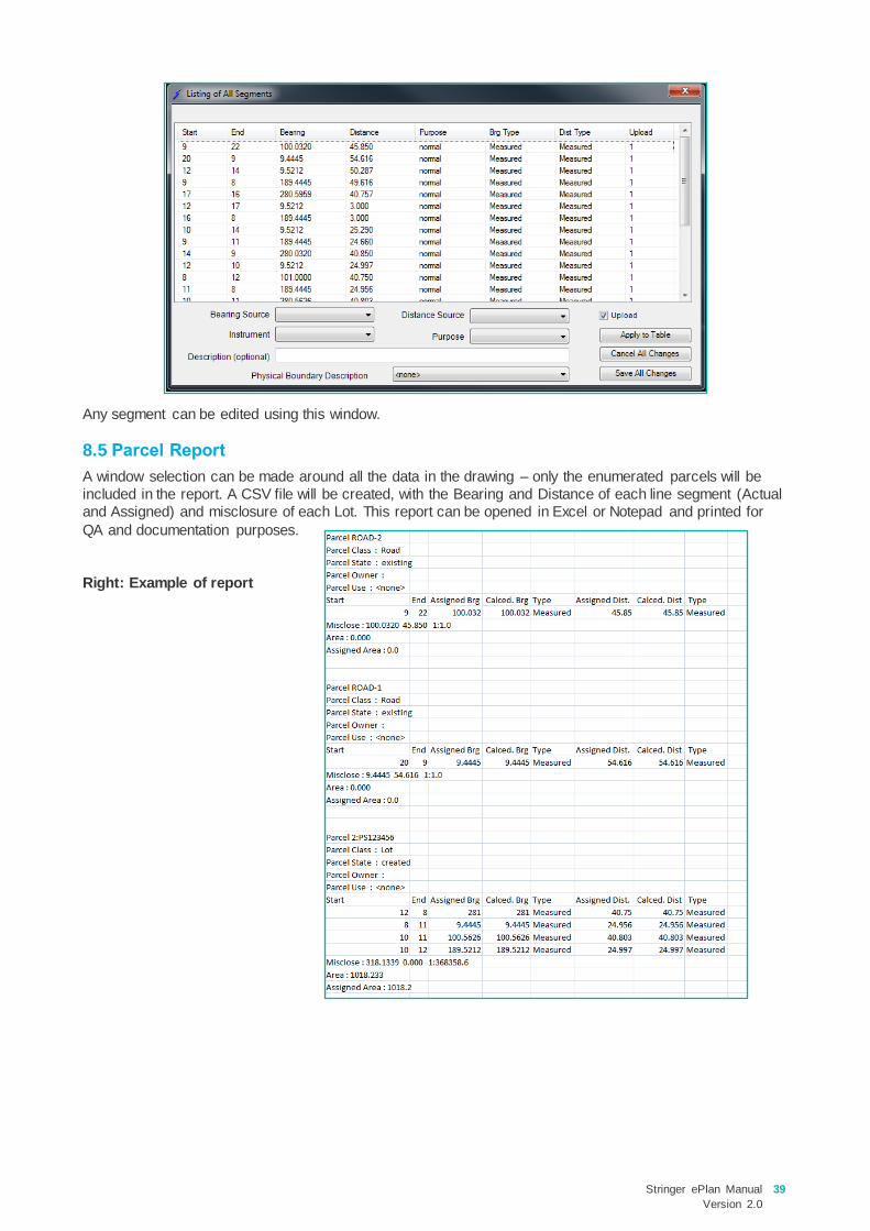
8.5 Parcel Report
A window selection can be made around all the data in the drawing – only the enumerated parcels will be
included in the report. A CSV file will be created, with the Bearing and Distance of each line segment (Actual
and Assigned) and misclosure of each Lot. This report can be opened in Excel or Notepad and printed for
QA and documentation purposes.
Right: Example of report

40 Stringer ePlan Manual
Version 2.0
Export
Click on the Export ePlan button to export an XML file. The XML file will be saved to the folder
selected. There are two options once the export has been saved as shown below:
Click ‘Validate File’ and ‘Visualisation of File’, to receive a validation report and a visualised plan in PDF
format from SPEAR.
NOTE: If the PDF file is already opened for visualisation or validation, and has not been closed, you
will receive the following error message on opening the PDF for the second time. To avoid the above
error, close the opened PDF first.
•Export ePlan - generates an ePlan file for lodgement
•Validate ePlan
•Create PDFExport

Stringer ePlan Manual
Version 2.0
41
NOTE: If you require any assistance resolving ePlan validation issues, please contact the ePlan team
on 03 9194 0612 and press 3, or send an email to [email protected]
42 Stringer ePlan Manual
Version 2.0
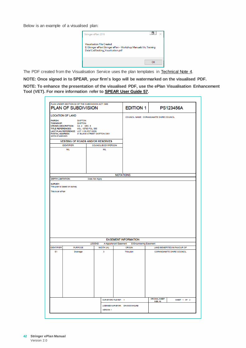
Below is an example of a visualised plan:
The PDF created from the Visualisation Service uses the plan templates in Technical Note 4.
NOTE: Once signed in to SPEAR, your firm’s logo will be watermarked on the visualised PDF.
NOTE: To enhance the presentation of the visualised PDF, use the ePlan Visualisation Enhancement
Tool (VET). For more information refer to SPEAR User Guide 57.

Stringer ePlan Manual
Version 2.0
43

44 Stringer ePlan Manual
Version 2.0
FAQ
The ePlan general FAQ’s are available at:
https://www.spear.land.vic.gov.au/spear/pages/eplan/about/faqs.shtml
The table below includes the questions which have been frequently asked by Stringer ePlan users.
No Question/Answer
1 What are the unsupported dealing types in ePlan?
The following are currently unsupported by ePlan:
• Multi-level Building Subdivisions – plans with boundaries defined by building are supported
• TLA Plans
• Crown Plans
These features will be rolled out progressively. Please contact the ePlan support team for any update.
2 How to submit an ePlan under Section 23, 24A or 32B that does not have any Plan Number?
If you would like to submit an ePlan under Section 23, 24A or 32B that does not have any Plan Number at the
time of submission to SPEAR, insert ‘LV-To-Supply’ in the ‘Plan Number’ box. This value will be replaced with
the relevant Dealing Number from the Victorian Online Title System (VOTS) once your ePlan is lodged at Land
Use Victoria.
3 How to add complex address?
The Name/Number field is a multipurpose field that records unit number, flat number, street number or range
and the number suffix.
The following is an example of the complete usage of the field:
Unit 25 Floor 4 45A-49B. This equates to Unit 25 on Floor 4 for the building in street number range 45A to 49B.
Simply omit the components not required when entering the name/number for your address. If a building or
complex name is required, tick the Complex Name and include the name of the building.
4 Do I need to round my observations?
No. ePlan requires all measurements to millimetres and seconds. The Visualiser will round the dimensions
based on the Victorian Cadastral Surveys Practice Directives published in July 2018.

Stringer ePlan Manual
Version 2.0
45
No Question/Answer
5 How do I capture Irregular Lines (Natural Boundaries)?
Natural boundaries and freehand lines are represented by an irregular line. To create an irregular line, ensure
that you tick the following checkbox ‘Irregular Bdy’ for the segments in Enumerate Parcel form.
ePlan requires the surveyor to textually describe irregular lines, e.g. a river boundary could be described as
‘edge of river’. Descriptions must be added after the line is created. To annotate an irregular line, select one
segment of that irregular line and add description to that segment in the Enumerate Segment tool.
6 How do I capture building boundaries?
ePlan does not need the bearing and distance to be recorded for the lines representing building boundaries.
Each building boundary line can be described in an ePlan as an ‘Interior Face’, ‘Exterior Face’, ‘Median’, or
‘Other’. To get building boundaries in the ePlan select the segment and enumerate it the correct attribute.

46 Stringer ePlan Manual
Version 2.0
No Question/Answer
7 How do I capture Road splays?
Road splays can be created using two topo lines. The road splay corners on the title boundary are plotted using
boundary points and the external corner is plotted using a sideshot point. See below for drawing a splay corner.
8 Do I need to add a normal line over the building boundary line in a parcel with a building boundary?
No, the building boundary line is sufficient, and it can be Median, Interior Face, Exterior Face, or Other
9 How do I create a Not In Subdivision (N.I.S) Lot in ePlan?
The NIS Lot geometry should be drawn and be enumerated with action of “referenced”. The name of this parcel
should be set according to the naming convention in section 4.4. Add a description like ‘N.I.S’ which is visualised
as a Lot identifier on the PDF.
10 How do I display a plan number of an extinguished (cancelled) Crown Allotment as a last plan reference
on front sheet?
The plan number (e.g. 1\TP123456) should be added in the ’Description’ field for the Crown Allotment Lot in
enumerated parcel form.
11 How should I name a Crown Allotment if there is no number for Crown Section?
If there is no Crown Section for a specific Crown Allotment, you must only enter the Crown Allotment section,
e.g. 31\PP5509.
12 How do I deal with multi-parish plans?
In this exceptional case, create all Parishes as Non-Spatial Parcels in the ‘Parcel Linkages’ with standard
naming for Parishes (e.g. PSH-3012). Ensure you have selected ’Existing’ for Action, ’Administrative Area’ for
Parcel Intent, ‘Administrative’ for Parcel Type, and name of parish (e.g. LONGWOOD) for Description and link
the corresponding Lots to each Parish. The multi-Parish Lots should be linked to all relevant Parishes.
13 How can I add connected permanent marks as a notation?
You need to add an annotation called ’General Plan Notation’ and include any notation. There are no text editor
facilities in the Annotation form.

Stringer ePlan Manual
Version 2.0
47
No Question/Answer
14 How can I assign a value of ‘Easement Purpose’ out of the drop-down list?
Create a new annotation (Easement Purpose) and reference it to the Non-Spatial Easement (EAS#) and put
your desired text as a description. This value will override the value of purpose assigned to the Easement
(EAS#) in the visualised PDF.
15 How can I add more origins to an Easement?
Create a new annotation (Easement Origin) and reference it to the non-spatial Easement (EAS#) and include
your desired text as description. This value will override the value of origin assigned to the Easement (EAS#) in
the visualised PDF.
16 How can I truncate road connections?
You don’t need to truncate road connections in CAD as the Visualiser will truncate the road connections
automatically. You can also use the truncation functionality available in the Visualisation Enhancement Tool.
17 How can I reverse the direction of walls hatches?
If you have created a Building Return plan feature and the direction of hatches is reversed, you need to go back
to CAD file and reverse the line direction using the “REVERSE” command in CAD.
18 How does the Visualiser label the building boundaries on PDF?
If there are different types of building boundaries (Median, Exterior Face, Interior Face or Other) within a plan,
the Visualiser labels the boundaries with the lowest cardinality on PDF and leave the building boundaries with
highest cardinality without label. It is also commented on the front sheet for clarification.
19 How can I assign more than one address to a single extinguished lot?
In ePlan, it is not possible to assign multiple addresses to a single extinguished parcel.
20 How can I show a dimension label which is not displayed on PDF?
Check the label in VET to ensure that it’s not hidden. If it is not hidden, create a Polyline on top of the existing
line in your CAD file and enumerate it as a Topo line.
21 What Internet browser can I use for visualising or enhancing a plan?
The following browsers are currently supported:
• Google Chrome (Recommended)
• Firefox
22 Do I need to link the defined Depth Limitation to lots in plan
No. Instead, you would be able to add any free text to General Plan notation in Annotation section.
23 How can I do back/forward bearing to add or deduct 180° to/from bearing?
No. This function is automatically done by visualisation service based on the best practice.
24 Is there any text editor/formatting functions in Annotation description, like line break, wrap, bullet …)
No. All the free text in annotation is created in a single line with default format

48 Stringer ePlan Manual
Version 2.0
No Question/Answer
25 How can I slightly change the bearing, distance, or area on PDF
Enumerate the corresponding geometry and assign a new value for bearing, distance, or area
26 Do I need to apply any rounding on bearing, distance, or area based on Survey Practice Handbook?
No. It is strongly recommended do not use or apply any rounding to measured survey data. ePlan services are
responsible to automatically round the measurements according to the Survey Practice Handbook.


