Optical f iber Bragg gratings are a unique optical f il-ter technology platform. They allow potentially hun-dreds of thousands of grating lines to be implemented.This unique feature allows many casual optical f il-ters with desired amplitude and phase spectrum tobe implemented. Recent development in inverse scat-tering of f iber Bragg gratings has provided a usefuldesign tool for such complex filters.1 –4 Making suchcomplex f ilters requires a grating-writing system withprecise control of grating amplitude and phase alongthe grating.5 –9 A recent demonstration of pure third-order dispersion compensation gratings showed that acontinuous writing system with controlled dephasingcan be built to give precise continuous grating ampli-tude and phase control.7
This new class of dispersion-compensating opticalfilters can lead to significant performance improve-ment in wavelength-division-multiplexing systems bycombining filtering and dispersion compensation andby increasing f lexibility in system dispersion mapping.These f ilters will also allow a wide range of opticalpulse shaping in a way that has not been possiblebefore, by performing complex pulse shape and pulsetransformation. Pulse shaping can be very useful ina laser system to generate a desired pulse train at theoutput. It can also be used to clean up complex chirpsof a pulse train, not just for linear and (or) quadraticchirp compensation. This new class of filter will alsopotentially make possible very complex codes in an op-tical code-division-multiplexing system.
Zero dispersion gratings with 99.9% ref lectivityhave also been demonstrated.5 Such strong gratingsmake possible channel dropping and, at the same time,provide suff icient transmission isolation to allow a newchannel to be added directly. Higher than 99.68%ref lectivity, corresponding to 25-dB transmissionisolation, is typically required for such applications.
0146-9592/03/100786-03$15.00/0
This ref lectivity is critical to ensure the cost effec-tiveness of such add–drop modules while takingfull advantage of newly available high-performancegratings.
A recent demonstration of dispersion-compensationgrating by the continuous phase-controlled writingprocess is yet another example of the capability ofthe technique.7 Pure third-order dispersion com-pensation is impossible to achieve with traditionalchirp control. It is, however, possible to achieve anyphase structure with the phase-control technique.This technique requires a grating design with acubic slow phase change in addition to multiplep phase jumps like those in zero-dispersion grat-ings. A dispersion-compensation grating designedby use of the layer-peeling algorithm is, therefore,far more complex than the zero-dispersion gratingdesign. Although demonstrated complex dispersion-compensation gratings have so far provided superbperformance and high-precision control in writing,they have less than 90% ref lectivity; i.e., they haveless than 10-dB transmission isolation. This lowref lectivity causes a higher insertion loss in a mul-tiplexing–demultiplexing configuration as well assignificant complexity in an add–drop configuration,where a minimum 25-dB transmission is required forabsence of channel cross talk to be ensured. A majordiff iculty in improving the ref lectivity of complexdispersion-compensation gratings is how to minimizenumerical error in the design stage by use of alayer-peeling algorithm. This algorithm is based onfront-end-first reconstruction of a grating structureby use of the impulse response from the front end ofthe grating. As the grating gets stronger, there isless light reaching the back end of the grating. Thiscauses poorer grating reconstruction toward the backend. The reconstruction at each stage also relies on
the already reconstructed grating data. This leadsto an accumulation of numerical error, which getsincreasingly worse toward the back of the gratingas the reconstruction proceeds. Minimizing thesenumerical errors in the reconstruction process is,therefore, critical in strong grating design, especiallyfor gratings with complex structures. Recently adesign tool was developed by Attolight Incorporated.This design tool uses a newly developed full-timedomain algorithm that is able to increase both accu-racy and efficiency over those of previous algorithms.We used this design tool for our design of a strongdispersion-compensation grating.
The writing system is based on a continuousphase-controlled writing configuration similar tothose in previous work.5 – 9 This system allows oneto control apodization and phase of the fiber Bragggrating continuously at each grating line. Specialattention is given to interferometer design, minimiz-ing timing jitter, precise translation, and accuratephase–apodization control. The fiber is movingconstantly on a high-precision motor with 0.3-nmresolution. A high-speed shutter system with lessthan 10-ns response time is utilized to repeatedlywrite a small grating structure �,200 mm� in thefiber as the f iber moves through the interferencepattern. The motion is carefully synchronized withthe shutter. A compact ultrastable interferometerdesign is designed and demonstrated. A phase maskis used to split the writing beam equally at the desiredangle. To minimize the phase perturbation intro-duced by any perturbations in the optical path, weuse an out-of-plane bidirectional ring-structure-basedinterferometer. The interferometer looks similar toa folded Mach–Zehnder interferometer with the in-terfering spot folded back to almost the splitting spot.However, a closer look at the beam paths shows thatit is different from a simple folded Mach–Zehnderdesign. Each beam is ref lected by one mirror inthe interferometer to the other mirror, then to theinterfering spot where the fiber is located. Afterthey are ref lected by the mirrors, the two beamsreturn to almost the same spot as the incident beam.With this design, the clockwise and counterclockwisebeams travel through almost the same optical path.The phase delay caused by any variation along theoptical path will be experienced by both interferencebeams. Therefore, on the fiber where the gratingis written, the interference pattern’s phase remainsstable. The fiber grating’s phase is varied by thepiezoelectric transducer controlled-phase mask, wherethe phase of interference fringe is accurately adjustedby a closed-loop control of the piezoelectric transducermotion.
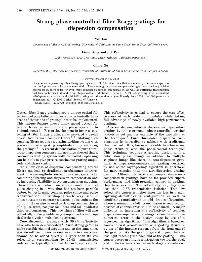
The first design is a 25-GHz 99.9% grating witha constant 2700-ps�nm dispersion, which combinesthe characteristics of both a dispersion compensatorand an optical filter. Therefore, the number of com-ponents in an optical network is minimized, and thenetwork is expected to have a better performancewith lower cost. The design is shown in Fig. 1. Thephase structure curve in Fig. 1 is continuous withsmoothed p phase jumps, which is very different from
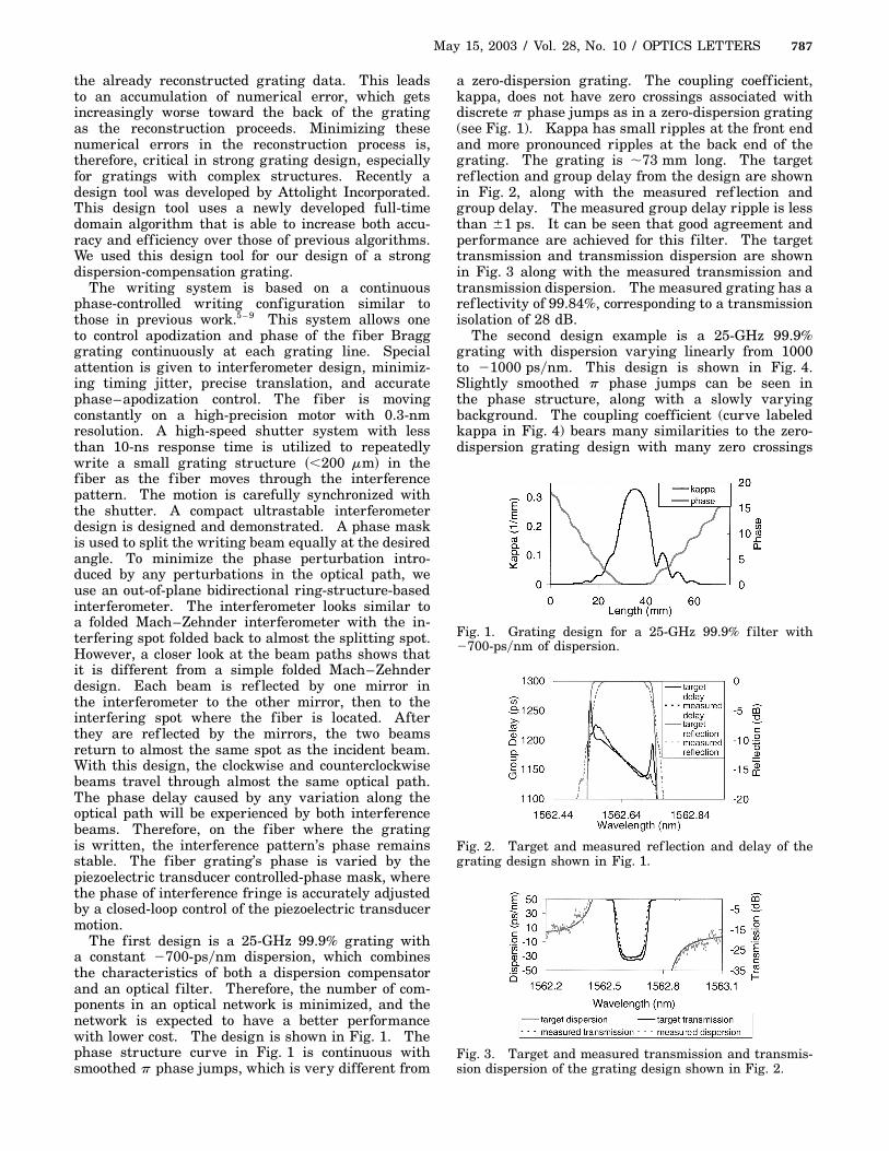
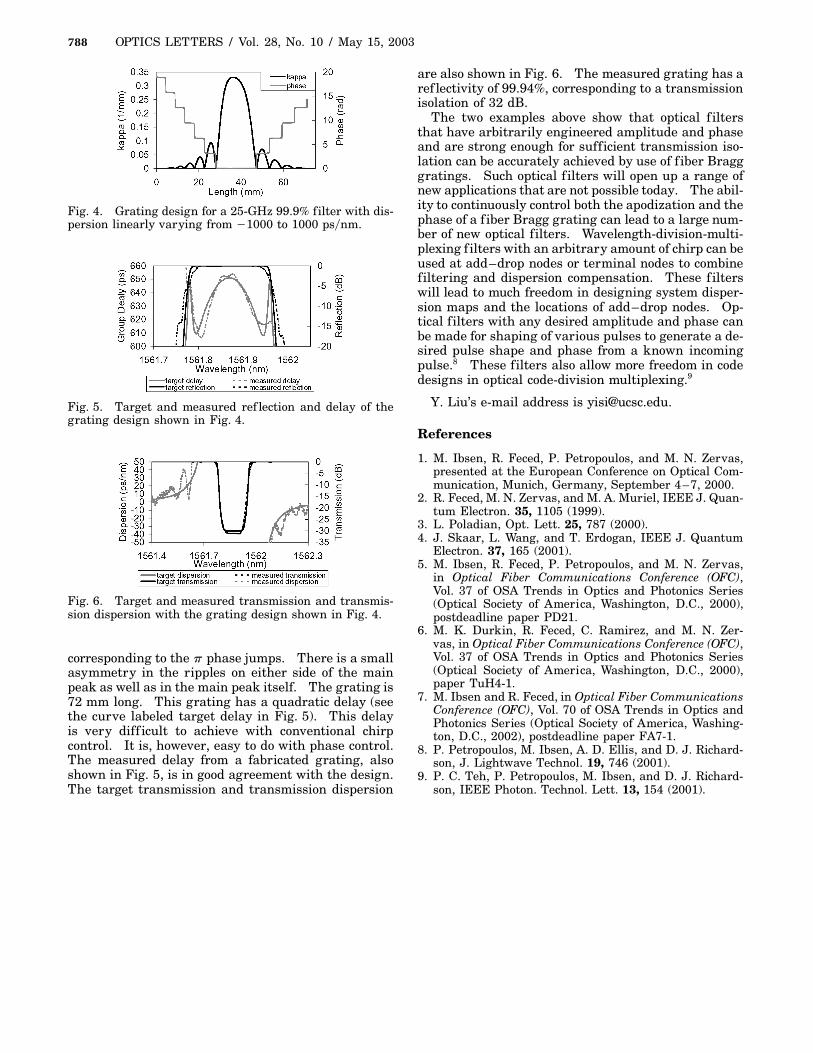
a zero-dispersion grating. The coupling coeff icient,kappa, does not have zero crossings associated withdiscrete p phase jumps as in a zero-dispersion grating(see Fig. 1). Kappa has small ripples at the front endand more pronounced ripples at the back end of thegrating. The grating is �73 mm long. The targetref lection and group delay from the design are shownin Fig. 2, along with the measured ref lection andgroup delay. The measured group delay ripple is lessthan 61 ps. It can be seen that good agreement andperformance are achieved for this filter. The targettransmission and transmission dispersion are shownin Fig. 3 along with the measured transmission andtransmission dispersion. The measured grating has aref lectivity of 99.84%, corresponding to a transmissionisolation of 28 dB.
The second design example is a 25-GHz 99.9%grating with dispersion varying linearly from 1000to 21000 ps�nm. This design is shown in Fig. 4.Slightly smoothed p phase jumps can be seen inthe phase structure, along with a slowly varyingbackground. The coupling coefficient (curve labeledkappa in Fig. 4) bears many similarities to the zero-dispersion grating design with many zero crossings
Fig. 1. Grating design for a 25-GHz 99.9% f ilter with2700-ps�nm of dispersion.
Fig. 2. Target and measured ref lection and delay of thegrating design shown in Fig. 1.
Fig. 3. Target and measured transmission and transmis-sion dispersion of the grating design shown in Fig. 2.
Fig. 4. Grating design for a 25-GHz 99.9% filter with dis-persion linearly varying from 21000 to 1000 ps�nm.
Fig. 5. Target and measured ref lection and delay of thegrating design shown in Fig. 4.
Fig. 6. Target and measured transmission and transmis-sion dispersion with the grating design shown in Fig. 4.
corresponding to the p phase jumps. There is a smallasymmetry in the ripples on either side of the mainpeak as well as in the main peak itself. The grating is72 mm long. This grating has a quadratic delay (seethe curve labeled target delay in Fig. 5). This delayis very diff icult to achieve with conventional chirpcontrol. It is, however, easy to do with phase control.The measured delay from a fabricated grating, alsoshown in Fig. 5, is in good agreement with the design.The target transmission and transmission dispersion
are also shown in Fig. 6. The measured grating has aref lectivity of 99.94%, corresponding to a transmissionisolation of 32 dB.
The two examples above show that optical f iltersthat have arbitrarily engineered amplitude and phaseand are strong enough for sufficient transmission iso-lation can be accurately achieved by use of f iber Bragggratings. Such optical f ilters will open up a range ofnew applications that are not possible today. The abil-ity to continuously control both the apodization and thephase of a f iber Bragg grating can lead to a large num-ber of new optical filters. Wavelength-division-multi-plexing f ilters with an arbitrary amount of chirp can beused at add–drop nodes or terminal nodes to combinefiltering and dispersion compensation. These f ilterswill lead to much freedom in designing system disper-sion maps and the locations of add–drop nodes. Op-tical filters with any desired amplitude and phase canbe made for shaping of various pulses to generate a de-sired pulse shape and phase from a known incomingpulse.8 These filters also allow more freedom in codedesigns in optical code-division multiplexing.9
1. M. Ibsen, R. Feced, P. Petropoulos, and M. N. Zervas,presented at the European Conference on Optical Com-munication, Munich, Germany, September 4–7, 2000.
2. R. Feced, M. N. Zervas, and M. A. Muriel, IEEE J. Quan-tum Electron. 35, 1105 (1999).
3. L. Poladian, Opt. Lett. 25, 787 (2000).4. J. Skaar, L. Wang, and T. Erdogan, IEEE J. Quantum
Electron. 37, 165 (2001).5. M. Ibsen, R. Feced, P. Petropoulos, and M. N. Zervas,
in Optical Fiber Communications Conference (OFC),Vol. 37 of OSA Trends in Optics and Photonics Series(Optical Society of America, Washington, D.C., 2000),postdeadline paper PD21.
6. M. K. Durkin, R. Feced, C. Ramirez, and M. N. Zer-vas, in Optical Fiber Communications Conference (OFC),Vol. 37 of OSA Trends in Optics and Photonics Series(Optical Society of America, Washington, D.C., 2000),paper TuH4-1.
7. M. Ibsen and R. Feced, in Optical Fiber CommunicationsConference (OFC), Vol. 70 of OSA Trends in Optics andPhotonics Series (Optical Society of America, Washing-ton, D.C., 2002), postdeadline paper FA7-1.
8. P. Petropoulos, M. Ibsen, A. D. Ellis, and D. J. Richard-son, J. Lightwave Technol. 19, 746 (2001).
9. P. C. Teh, P. Petropoulos, M. Ibsen, and D. J. Richard-son, IEEE Photon. Technol. Lett. 13, 154 (2001).