Understanding and controlling crystallographic tex-ture is important for material design. Iron crystal with body-centered cubic crystal structure exhibits excellent magnetic properties along the <001> , which is the axes of easy magnetization. Therefore, enormous research has been carried out using steel sheet materials to align the <001> axes parallel to a magnetization axis, which is usu-ally in the sheet surface, and develop specific textures with Goss ({110}<001>), cube ({100}<001>) or rotated cube ({100}<011>).1,2)†
Lee et al.4) reported that recrystallized {100}<001> grains were obtained in 2.0% Si steel by coarsening grain size before cold rolling and employing a high temperature annealing at 900°C. Sha et al.5) reported a cube texture in a 2.8% Si steel processed by a twin-roll casting method. How-ever, the ODF intensities of these cube orientations in the φ 2=45° sections are no more than 5.0, which is significantly lower than the value more than 100 in the Goss orientation
Strongly Developed Texture Components near Rotated Cube Orientation during Recrystallization in a Severely Cold Rolled Low Carbon Steel
Shigehiro TAKAJO,1,2)* Sven C. VOGEL1) and Yasuyuki HAYAKAWA2,3)
1) Materials Science and Technology Division, Los Alamos National Laboratory, Los Alamos, NM, 87545 USA.2) Electrical Steel Research Department, JFE Steel Corporation, Kurashiki, 712-8511 Japan.3) Department of Materials Science, Graduate School of Engineering, Tohoku University, Aoba-yama 6-6-02, Sendai, 980-8579 Japan.
(Received on August 21, 2018; accepted on November 8, 2018)
Extraordinarily strong recrystallization texture components near rotated cube ({100}<011>) developed in a low carbon steel processed with a severe cold rolling at 99.8% reduction followed by an annealing at 550°C or more. The rotated cube orientation is beneficial for magnetic applications, while it has been recognized as an orientation difficult to recrystallize. Unlike the conventional 90% cold rolling sample, the 99.8% cold rolling sample showed an unusually strong α fiber deformation texture and a fine lamellar structure understood from previous work to be generated via grain subdivision. In addition, texture analy-sis of a partially recrystallized sample at lower temperature anneal of 450°C revealed that the {100}<0 7 10> oriented grains recrystallized discontinuously from near the domain boundaries in the 99.8% cold rolled sample, while the {100}<011> oriented grains were likely to recrystallize continuously. Kernel average misorientation analysis of EBSD data suggested that the {100}<011> oriented grains underwent a faster recovery than the other α fiber orientations, resulting in a fast nucleation and growing toward the deformed matrix. Since this oriented nucleation of {100}<011> oriented grains was not observed in 99.8% cold rolled pure iron and 99.2% cold rolled interstitial free steel, solute carbons in the steel would play a significant role for the selective and fast recovery of the {100}<011> oriented grains during the annealing process.
† Explanations of component descriptions can be found in 3).
in grain oriented electrical steels.6)
Among the three orientations aligning <001> perpen-dicular to the plane normal explained above, the rotated cube has been recognized as an orientation difficult to be obtained in a recrystallization process,7) since it shows a lower stored energy during a conventional cold rolling than the other orientations.8–10) Therefore, only limited methods, such as a vacuum annealing11) or a dynamic compression with a very low strain rate,12) could successfully obtain the rotated cube texture.
Quite recently, Tomita et al.13,14) reported strong {100}<012> texture component with the ODF value more than 20 in several steels by means of a severe cold rolling (99.8% reduction). In the study, despite the result that the ND//<001> oriented grains showed a high stored energy compared to other α fiber grains, they clarified that the orientations of α fiber were equally nucleated from the deformed matrix and, therefore, the cold rolling texture was preserved after recrystallization. It was also demonstrated that the {100}<012> texture enhanced during subsequent grain growth at higher temperature anneal. Although,
excellent magnetic properties cannot be expected in the {100}<012> textured steel, since the two symmetrically equivalent orientations of {100}<012> , e.g., the [120] and [120] directions, cancel the magnetic anisotropies with each other in the bulk property, the severe cold rolling process exhibits new metallurgical phenomena which have not fully been captured but could potentially provide unconventional textures or materials as already proved in accumulative roll-bonding (ARB) process.15,16)
In the present study, it is first shown that extraordinarily strong recrystallization texture components near rotated cube ({100}<011>~{100}<0 7 10>) developed in a low carbon steel processed with a severe cold rolling at 99.8% reduction followed by an annealing at 700°C, and the texture data were compared with that of 90% cold rolled sample. The primary objective of this study is to investigate the recrystallization mechanism in the severely cold rolled low carbon steel by means of microstructural analyses using electron back-scatter diffraction (EBSD) method. The grain level microstructural analyses from RD (rolling direction)-ND (normal direction) material sections, which have usually been employed in the EBSD study, was considered as inadequate for a study on severely cold rolled samples because of extremely condensed grain boundaries of prior grains in the normal direction. Therefore, the obser-vation from the RD-TD (transverse direction) section was mostly applied in this study, which successfully captured a new characteristic microstructure of the material.
2. Experimental Procedure
A low carbon steel ingot was prepared by a vacuum induction melting method, which contained few amount of impurity elements except carbon. The result of the chemical analysis on the ingot is shown in Table 1. The ingot was reheated to 1 100°C for 1 hour and hot-rolled at a finishing temperature of 950°C in the austenitic domain followed by air cooling. The obtained hot rolled steel plates were ground to remove surface scale layers, cold rolled at 90% reduc-tion, 98% reduction and 99.8% reduction, then heated to a temperature of 450°C, 550°C and 700°C for 2 minutes with an Ar flow, resulting in a matrix of 9 samples. The rate of increasing temperature in the heating process was 10°C/sec in the temperature range from 400°C to 700°C.
The macroscopic crystallographic texture was measured using X-ray diffraction and the Schulz method17) with the Co-Kα radiation from an area more than 5×5 mm2 at half thickness, which was presented as measured {110}, {200} and {211} pole figures. The corresponding ODFs repre-sented by Bunge’s notation were then calculated from them using the Pawlik’s method.18)
EBSD measurements were carried out using SEM (Philips XL-30), where a 20-kV electron beam was scanned, with step sizes of 0.6–2.5 μm for recrystallized microstruc-ture and 0.08–0.15 μm for deformed microstructure, on the
cut-and-polished material surface. The final polishing was performed using a colloidal silica solution for 30 min. In this paper, the tolerance angle for definitions of a specific crystal orientation was 15° unless otherwise noted.
The EBSD datasets were subjected to a clean-up proce-dure using neighbor confidence index (CI) correlation with a minimum CI of 0.05. After the clean-up process, low CI and mis-indexed data were replaced with the neighbor data that had a higher CI. The fraction of points changed in each data set was less than 15% for recrystallized microstructure and 32% for deformed microstructure. The EBSD data analysis was performed using an OIM system (EDAX Inc.; TSL OIM analysis ver.5.3.1). Along with the standard texture analysis, kernel average misorientation of all neighboring points with respect to 2nd neighbor19) was calculated for each data point to characterize the local misorientation.
3. Results
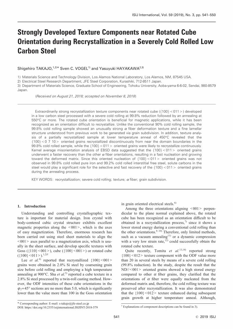
3.1. Macroscopic TextureFigure 1 shows ODF sections of 90%, 98% and 99.8%
cold rolled samples before and after annealing at 700°C for 2 minutes. The rotated cube orientation and two characteris-tic steel texture components, namely, the α fiber and γ fiber develop in as cold rolled samples.20) The α fiber increases with increasing reduction while the γ fiber decreases. The recrystallization texture of the 90% cold rolled sample shows {h,1,1}<1/h,1,2> fiber as well as {111}<112> component. The maximum ODF intensity in the φ 2=45° section is no more than 3.2. On the other hand, the 98% cold rolled sample shows a strongly developed texture near {411}<148> and {100}<011> and shows a strong rotated cube texture with the ODF intensity of 30 at (001)[110] orientation. There are two major peaks of ODF intensity at {100}<011> orientation and {100}<0 7 10> orienta-tion (one of the orientation components corresponding to Φ=0° and φ 1=10° in φ 2=45° section). In this study, the orientations whose misorientation angle from {100}<011> is within 10° including {100}<0 7 10> , will be referred to as the rotated cube.
3.2. Microstructure and Texture Evolution after Recrystallization
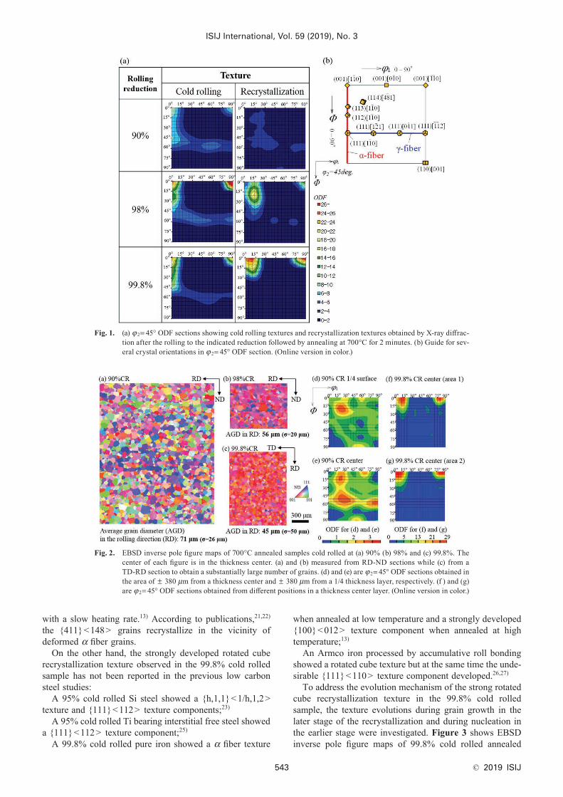
As shown in Fig. 2, the microstructure recrystallizes fully after annealing at 700°C, and the average grain diameter in the rolling direction decreases with increasing the reduction. The 90% cold rolled sample shows a texture variation along the normal direction and γ fiber develops more in the thick-ness center than the surface layer. The 99.8% cold rolled sample shows a small texture variation in a thickness center because of the small observation area in the EBSD analy-sis used here. The ODF was analyzed in 5 positions with approximately 1.0×1.5 mm2 at the thickness center for the 99.8% cold rolled sample, and 4 out of 5 showed the maxi-mum intensity at {100}<0 7 10> like Fig. 2(f) while the other showed that near {100}<011> orientations like Fig. 2(g).
The {411}<148> texture component in the 90% cold rolled and recrystallized sample is consistent with previ-ous data in a low carbon steel,21) a pure iron22) and a 3% Si steel,23) but different from a Ti and Nb bearing inter-stitial free steel24) and a pure iron presumably annealed
with a slow heating rate.13) According to publications,21,22) the {411}<148> grains recrystallize in the vicinity of deformed α fiber grains.
On the other hand, the strongly developed rotated cube recrystallization texture observed in the 99.8% cold rolled sample has not been reported in the previous low carbon steel studies:
A 95% cold rolled Si steel showed a {h,1,1}<1/h,1,2> texture and {111}<112> texture components;23)
A 95% cold rolled Ti bearing interstitial free steel showed a {111}<112> texture component;25)
A 99.8% cold rolled pure iron showed a α fiber texture
when annealed at low temperature and a strongly developed {100}<012> texture component when annealed at high temperature;13)
An Armco iron processed by accumulative roll bonding showed a rotated cube texture but at the same time the unde-sirable {111}<110> texture component developed.26,27)
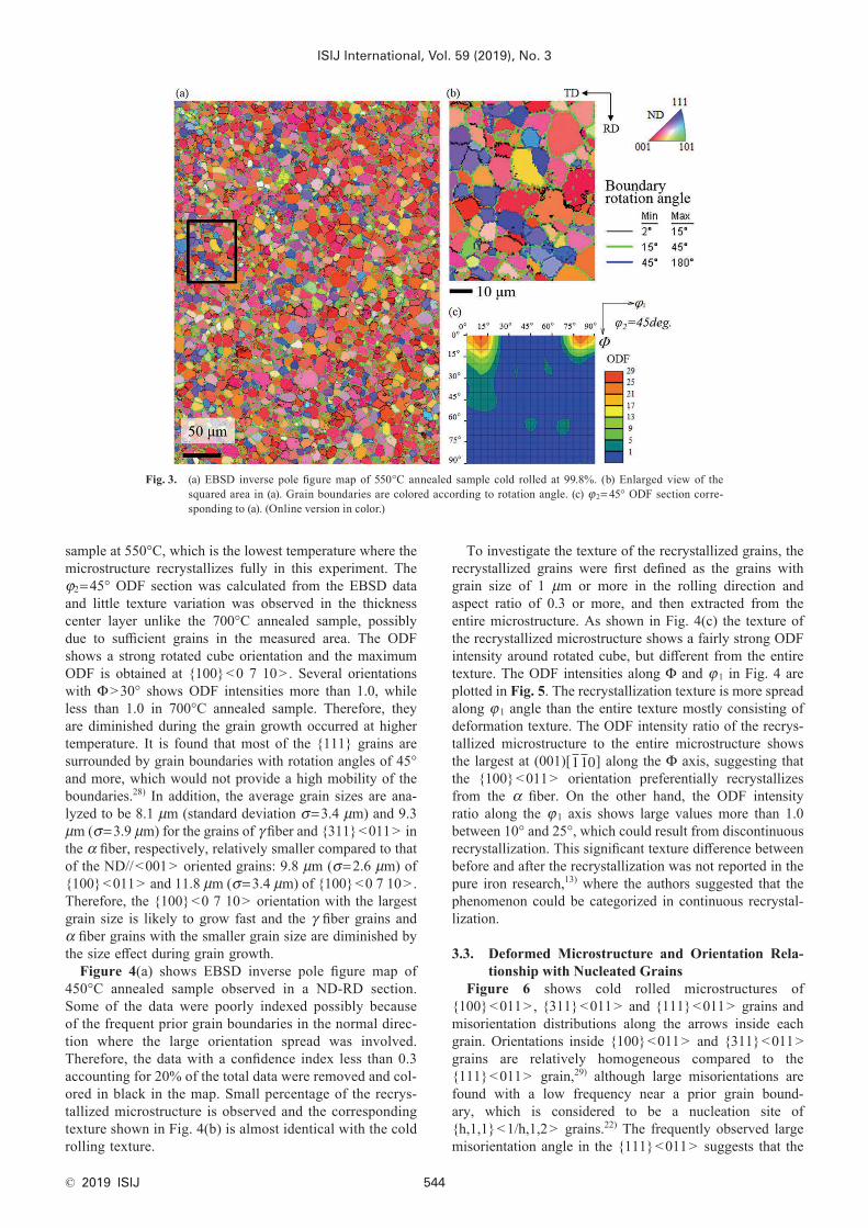
To address the evolution mechanism of the strong rotated cube recrystallization texture in the 99.8% cold rolled sample, the texture evolutions during grain growth in the later stage of the recrystallization and during nucleation in the earlier stage were investigated. Figure 3 shows EBSD inverse pole figure maps of 99.8% cold rolled annealed
Fig. 1. (a) φ 2= 45° ODF sections showing cold rolling textures and recrystallization textures obtained by X-ray diffrac-tion after the rolling to the indicated reduction followed by annealing at 700°C for 2 minutes. (b) Guide for sev-eral crystal orientations in φ 2= 45° ODF section. (Online version in color.)
Fig. 2. EBSD inverse pole figure maps of 700°C annealed samples cold rolled at (a) 90% (b) 98% and (c) 99.8%. The center of each figure is in the thickness center. (a) and (b) measured from RD-ND sections while (c) from a TD-RD section to obtain a substantially large number of grains. (d) and (e) are φ 2= 45° ODF sections obtained in the area of ± 380 μm from a thickness center and ± 380 μm from a 1/4 thickness layer, respectively. (f ) and (g) are φ 2= 45° ODF sections obtained from different positions in a thickness center layer. (Online version in color.)
sample at 550°C, which is the lowest temperature where the microstructure recrystallizes fully in this experiment. The φ2=45° ODF section was calculated from the EBSD data and little texture variation was observed in the thickness center layer unlike the 700°C annealed sample, possibly due to sufficient grains in the measured area. The ODF shows a strong rotated cube orientation and the maximum ODF is obtained at {100}<0 7 10> . Several orientations with Φ>30° shows ODF intensities more than 1.0, while less than 1.0 in 700°C annealed sample. Therefore, they are diminished during the grain growth occurred at higher temperature. It is found that most of the {111} grains are surrounded by grain boundaries with rotation angles of 45° and more, which would not provide a high mobility of the boundaries.28) In addition, the average grain sizes are ana-lyzed to be 8.1 μm (standard deviation σ=3.4 μm) and 9.3 μm (σ=3.9 μm) for the grains of γ fiber and {311}<011> in the α fiber, respectively, relatively smaller compared to that of the ND//<001> oriented grains: 9.8 μm (σ=2.6 μm) of {100}<011> and 11.8 μm (σ=3.4 μm) of {100}<0 7 10> . Therefore, the {100}<0 7 10> orientation with the largest grain size is likely to grow fast and the γ fiber grains and α fiber grains with the smaller grain size are diminished by the size effect during grain growth.
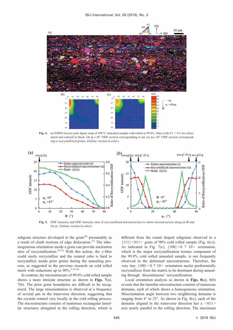
Figure 4(a) shows EBSD inverse pole figure map of 450°C annealed sample observed in a ND-RD section. Some of the data were poorly indexed possibly because of the frequent prior grain boundaries in the normal direc-tion where the large orientation spread was involved. Therefore, the data with a confidence index less than 0.3 accounting for 20% of the total data were removed and col-ored in black in the map. Small percentage of the recrys-tallized microstructure is observed and the corresponding texture shown in Fig. 4(b) is almost identical with the cold rolling texture.
To investigate the texture of the recrystallized grains, the recrystallized grains were first defined as the grains with grain size of 1 μm or more in the rolling direction and aspect ratio of 0.3 or more, and then extracted from the entire microstructure. As shown in Fig. 4(c) the texture of the recrystallized microstructure shows a fairly strong ODF intensity around rotated cube, but different from the entire texture. The ODF intensities along Φ and φ 1 in Fig. 4 are plotted in Fig. 5. The recrystallization texture is more spread along φ 1 angle than the entire texture mostly consisting of deformation texture. The ODF intensity ratio of the recrys-tallized microstructure to the entire microstructure shows the largest at (001)[110] along the Φ axis, suggesting that the {100}<011> orientation preferentially recrystallizes from the α fiber. On the other hand, the ODF intensity ratio along the φ 1 axis shows large values more than 1.0 between 10° and 25°, which could result from discontinuous recrystallization. This significant texture difference between before and after the recrystallization was not reported in the pure iron research,13) where the authors suggested that the phenomenon could be categorized in continuous recrystal-lization.
3.3. Deformed Microstructure and Orientation Rela-tionship with Nucleated Grains
Figure 6 shows cold rolled microstructures of {100}<011> , {311}<011> and {111}<011> grains and misorientation distributions along the arrows inside each grain. Orientations inside {100}<011> and {311}<011> grains are relatively homogeneous compared to the {111}<011> grain,29) although large misorientations are found with a low frequency near a prior grain bound-ary, which is considered to be a nucleation site of {h,1,1}<1/h,1,2> grains.22) The frequently observed large misorientation angle in the {111}<011> suggests that the
Fig. 3. (a) EBSD inverse pole figure map of 550°C annealed sample cold rolled at 99.8%. (b) Enlarged view of the squared area in (a). Grain boundaries are colored according to rotation angle. (c) φ 2= 45° ODF section corre-sponding to (a). (Online version in color.)
subgrain structure developed in the grain30) presumably as a result of climb motions of edge dislocation.31) The inho-mogeneous orientation inside a grain can provide nucleation sites of recrystallization.32,33) With this notion, the γ fiber could easily recrystallize and the rotated cube is hard to recrystallize inside prior grains during the annealing pro-cess, as suggested in the previous research on cold rolled steels with reductions up to 90%.9,33,34)
In contrast, the microstructure of 99.8% cold rolled sample shows a more intricate structure as shown in Figs. 7(a), 7(b). The prior grain boundaries are difficult to be recog-nized. The large misorientation is observed at a frequency of several μm in the transverse direction, suggesting that the crystals rotated very locally in the cold rolling process. The microstructure consists of numerous rectangular lamel-lar structures elongated in the rolling direction, which is
different from the round shaped subgrains observed in a {111}<011> grain of 90% cold rolled sample (Fig. 6(c)). As indicated in Fig. 7(c), {100}<0 7 10> orientation, which is the major recrystallization texture component of the 99.8% cold rolled annealed sample, is not frequently observed in the deformed microstructure. Therefore, the very tiny {100}<0 7 10> orientation nuclei preferentially recrystallizes from the matrix to be dominant during anneal-ing through `discontinuous’ recrystallization.
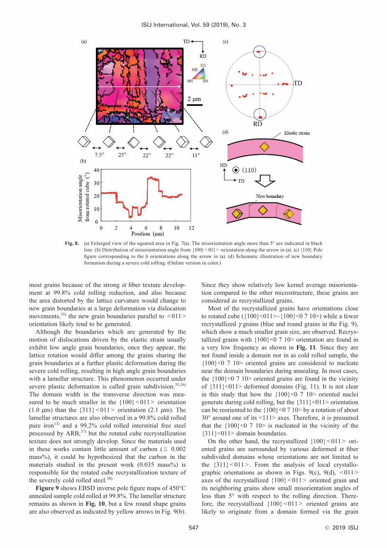
Local orientation analysis as shown in Figs. 8(a), 8(b) reveals that the lamellar microstructure consists of numerous domains, each of which shows a homogeneous orientation. Misorientation angle between two neighboring domains is ranging from 4° to 25°. As shown in Fig. 8(c), each of the domains aligned in the transverse direction has a <011> axis nearly parallel to the rolling direction. The maximum
Fig. 4. (a) EBSD inverse pole figure map of 450°C annealed sample cold rolled at 99.8%. Data with CI < 0.3 are elimi-nated and colored in black. (b) φ 2= 45° ODF section corresponding to (a). (c) φ 2= 45° ODF section correspond-ing to recrystallized grains. (Online version in color.)
Fig. 5. ODF intensity and ODF intensity ratio of recrystallized microstructure to entire microstructure along (a) Φ and (b) φ1. (Online version in color.)
misorientation between the <011> axes of the domains is less than 4°. These facts suggest a mechanism that the fine domain structure is formed as a result of local reorientations around a RD//<011> as shown in Fig. 8(d). As Toth et
al.35) suggested, lattice curvatures due to a non-uniform lat-tice rotation near grain boundaries would induce an elastic strain. Because most of the grain boundaries are parallel to the rolling direction and are also parallel to the <011> in
Fig. 6. EBSD inverse pole figure maps of 90% cold rolled sample corresponding to grains with (a) {100}< 011>, (b) {311}< 011> and (c) {111}< 011>, respectively. (d) (e) (f) Point to point misorientation along the arrows shown in (a) (b) (c). (Online version in color.)
Fig. 7. (a) EBSD inverse pole figure map of 99.8% cold rolled sample. The misorientation angle more than 15° are indi-cated in black line. (b) Point to point misorientation along the arrows shown in (a). (c) {100} pole figure of 99.8% cold rolled sample. The arrows indicate positions for {100}< 0 7 10 > orientations. (Online version in color.)
most grains because of the strong α fiber texture develop-ment at 99.8% cold rolling reduction, and also because the area distorted by the lattice curvature would change to new grain boundaries at a large deformation via dislocation movements,35) the new grain boundaries parallel to <011> orientation likely tend to be generated.
Although the boundaries which are generated by the motion of dislocations driven by the elastic strain usually exhibit low angle grain boundaries, once they appear, the lattice rotation would differ among the grains sharing the grain boundaries at a further plastic deformation during the severe cold rolling, resulting in high angle grain boundaries with a lamellar structure. This phenomenon occurred under severe plastic deformation is called grain subdivision.35,36) The domain width in the transverse direction was mea-sured to be much smaller in the {100}<011> orientation (1.0 μm) than the {311}<011> orientation (2.1 μm). The lamellar structures are also observed in a 99.8% cold rolled pure iron13) and a 99.2% cold rolled interstitial free steel processed by ARB,37) but the rotated cube recrystallization texture does not strongly develop. Since the materials used in these works contain little amount of carbon (≦ 0.002 mass%), it could be hypothesized that the carbon in the materials studied in the present work (0.035 mass%) is responsible for the rotated cube recrystallization texture of the severely cold rolled steel.38)
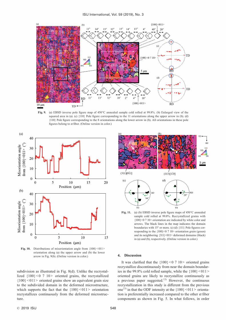
Figure 9 shows EBSD inverse pole figure maps of 450°C annealed sample cold rolled at 99.8%. The lamellar structure remains as shown in Fig. 10, but a few round shape grains are also observed as indicated by yellow arrows in Fig. 9(b).
Since they show relatively low kernel average misorienta-tion compared to the other microstructure, these grains are considered as recrystallized grains.
Most of the recrystallized grains have orientations close to rotated cube ({100}<011>~{100}<0 7 10>) while a fewer recrystallized γ grains (blue and round grains in the Fig. 9), which show a much smaller grain size, are observed. Recrys-tallized grains with {100}<0 7 10> orientation are found in a very low frequency as shown in Fig. 11. Since they are not found inside a domain nor in as cold rolled sample, the {100}<0 7 10> oriented grains are considered to nucleate near the domain boundaries during annealing. In most cases, the {100}<0 7 10> oriented grains are found in the vicinity of {311}<011> deformed domains (Fig. 11). It is not clear in this study that how the {100}<0 7 10> oriented nuclei generate during cold rolling, but the {311}<011> orientation can be reoriented to the {100}<0 7 10> by a rotation of about 30° around one of its <111> axes. Therefore, it is presumed that the {100}<0 7 10> is nucleated in the vicinity of the {311}<011> domain boundaries.
On the other hand, the recrystallized {100}<011> ori-ented grains are surrounded by various deformed α fiber subdivided domains whose orientations are not limited to the {311}<011> . From the analysis of local crystallo-graphic orientations as shown in Figs. 9(c), 9(d), <011> axes of the recrystallized {100}<011> oriented grain and its neighboring grains show small misorientation angles of less than 5° with respect to the rolling direction. There-fore, the recrystallized {100}<011> oriented grains are likely to originate from a domain formed via the grain
Fig. 8. (a) Enlarged view of the squared area in Fig. 7(a). The misorientation angle more than 5° are indicated in black line. (b) Distribution of misorientation angle from {100}< 011> orientation along the arrow in (a). (c) {110} Pole figure corresponding to the 6 orientations along the arrow in (a). (d) Schematic illustration of new boundary formation during a severe cold rolling. (Online version in color.)
subdivision as illustrated in Fig. 8(d). Unlike the recrystal-lized {100}<0 7 10> oriented grains, the recrystallized {100}<011> oriented grains show an equivalent grain size to the subdivided domain in the deformed microstructure, which supports the fact that the {100}<011> orientation recrystallizes continuously from the deformed microstruc-ture.
4. Discussion
It was clarified that the {100}<0 7 10> oriented grains recrystallize discontinuously from near the domain boundar-ies in the 99.8% cold rolled sample, while the {100}<011> oriented grains are likely to recrystallize continuously as a previous paper suggested.13) However, the continuous recrystallization in this study is different from the previous one13) in that the ODF intensity at the {100}<011> orienta-tion is preferentially increased compared to the other α fiber components as shown in Fig. 5. In what follows, in order
Fig. 10. Distributions of misorientation angle from {100}< 011> orientation along (a) the upper arrow and (b) the lower arrow in Fig. 9(b). (Online version in color.)
Fig. 11. (a) (b) EBSD inverse pole figure maps of 450°C annealed sample cold rolled at 99.8%. Recrystallized grains with {100}<0 7 10> orientation are indicated by white color and arrows. The black lines in the map indicates the domain boundaries with 15° or more. (c) (d) {111} Pole figures cor-responding to the {100}<0 7 10> orientation grain (green) and its neighboring {311}<011> deformed domains (black) in (a) and (b), respectively. (Online version in color.)
Fig. 9. (a) EBSD inverse pole figure map of 450°C annealed sample cold rolled at 99.8%. (b) Enlarged view of the squared area in (a). (c) {110} Pole figure corresponding to the 11 orientations along the upper arrow in (b). (d) {110} Pole figure corresponding to the 8 orientations along the lower arrow in (b). All orientations in these pole figures belong to α fiber. (Online version in color.)
to investigate the mechanism of the preferential growth of these oriented grains, a recovery behavior is speculated by a kernel average misorientation analysis. The analysis has been used to evaluate the local strain39–41) of each orienta-tion, although not directly associated with strain, dislocation density or stored energy.
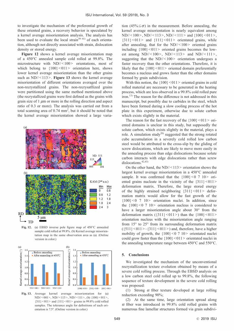
Figure 12 shows a kernel average misorientation map of a 450°C annealed sample cold rolled at 99.8%. The microstructure with ND//<100> orientations, most of which belong to {100}<011> orientation here, shows lower kernel average misorientation than the other grains such as ND//<113> . Figure 13 shows the kernel average misorientation of different orientations averaged over the non-recrystallized grains. The non-recrysatllized grains were partitioned using the same method mentioned above (the recrystallized grains were first defined as the grains with grain size of 1 μm or more in the rolling direction and aspect ratio of 0.3 or more). The analysis was carried out from a total scanning area of 0.74 mm2, but it should be noted that the kernel average misorientation showed a large varia-
tion (45%≦σ ) in the measurement. Before annealing, the kernel average misorientation is nearly equivalent among ND//<100> , ND//<113> , ND//<111> and {100}<011> , {311}<011> and {111}<011> orientated grains, while after annealing, that for the ND//<100> oriented grains including {100}<011> oriented grains becomes the low-est among ND//<100> , ND//<113> and ND//<111> , suggesting that the ND//<100> orientation undergoes a faster recovery than the other orientations. Therefore, it is likely that the {100}<011> oriented domain preferentially becomes a nucleus and grows faster than the other domains formed by grain subdivision.
With this notion, the {100}<011> oriented grains in cold rolled material are necessary to be generated in the heating process, which are less observed in a 99.8% cold rolled pure iron.13) The reason for the difference is not addressed in this manuscript, but possibly due to carbides in the steel, which have been formed during a slow cooling process of the hot plate in this experiment, otherwise due to solute carbon which exists slightly in the material.
The reason for the fast recovery of the {100}<011> ori-ented domains is unclear in this study, but supposedly the solute carbon, which exists slightly in the material, plays a role. A simulation study20) suggested that the strong rotated cube accumulation in a severely cold rolled low carbon steel would be attributed to the cross-slip by the gliding of screw dislocations, which are likely to move more easily in the annealing process than edge dislocations because solute carbon interacts with edge dislocations rather than screw dislocations.42,43)
On the other hand, the ND//<113> orientation shows the largest kernel average misorientation in a 450°C annealed sample. It was confirmed that the {100}<0 7 10> ori-ented grains nucleate in the vicinity of the {311}<011> deformation matrix. Therefore, the large stored energy of the highly strained neighboring {311}<011> defor-mation matrix would allow for the fast growth of the {100}<0 7 10> orientation nuclei. In addition, since the {100}<0 7 10> orientation nucleus is considered to have a larger misorientation angle about 30° from the deformation matrix ({311}<011>) than the {100}<011> orientation nucleus with the misorientation angle ranging from 15° to 25° from its surrounding deformation matrix ({511}<011>–{311}<011>) and, therefore, have a higher mobility of growth, the {100}<0 7 10> orientated nuclei could grow faster than the {100}<011> orientated nuclei in the annealing temperature range between 450°C and 550°C.
5. Conclusions
We investigated the mechanism of the unconventional recrystallization texture evolution obtained by means of a severe cold rolling process. Through the EBSD analysis on a low carbon steel cold rolled up to 99.8%, the following sequence of texture development in the severe cold rolling was proposed:
(1) Strong α fiber texture developed at large rolling reduction exceeding 90%;
(2) At the same time, large orientation spread along α fiber was introduced in 99.8% cold rolled grains with numerous fine lamellar structures formed via grain subdivi-
Fig. 12. (a) EBSD inverse pole figure map of 450°C annealed sample cold rolled at 99.8%. (b) Kernel average misorien-tation map in the same observation area as (a). (Online version in color.)
Fig. 13. Average kernel average misorientation for (a)ND//< 001>, ND//<113>, ND//<111>, (b) {100}< 011>, {311}< 011> and {111}< 011> grains in 99.8% cold rolled samples. The tolerance angle for definitions of each ori-entation is 7.5°. (Online version in color.)
sion process;(3) Among the α fiber orientations in the 99.8%
cold rolled low carbon steel, lamellar structures with {100}<011> orientation underwent a faster recovery dur-ing annealing process than the other α fiber components and preferentially recrystallized via continuous recrystallization. In addition, the {100}<0 7 10> oriented grains preferen-tially nucleated from the domain boundaries via discontinu-ous recrystallization in the deformed matrix.
Thus, strong recrystallization texture components near rotated cube were attained in a severely cold rolled low carbon steel.
AcknowledgmentsS. T. gratefully acknowledges support from JFE Steel
Corporation for his PhD thesis research at LANL and help-ful discussions with Professor Dr. I. J. Beyerlein, UC Santa Barbara.
REFERENCES
1) Y. Hayakawa: Sci. Technol. Adv. Mater., 18 (2017), 480.2) L. Kestens and S. Jacobs: Texture Stress Microstruct., 2008 (2008),
Article ID 173083.3) L. A. I. Kestens and H. Pirgazi: Mater. Sci. Technol., 32 (2016),
1303.4) K. M. Lee, M. Y. Huh, H. J. Lee, J. T. Park, J. S. Kim, E. J. Shin
and O. Engler: J. Magn. Magn. Mater., 396 (2015), 53.5) Y. H. Sha, C. Sun, F. Zhang, D. Patel, X. Chen, S. R. Kalidindi and
L. Zuo: Acta Mater., 76 (2014), 106.6) T. Imamura, Y. Shingaki and Y. Hayakawa: Metall. Mater. Trans. A,
44 (2013), 1785.7) H. Hu: Recovery and Recrystallization of Metals, ed. by L. Himmel,
Gordon and Breach Science Publishers, New York, (1963), 311.8) R. L. Every and M. Hatherly: Texture, 1 (1972), 183.9) N. Rajmohan, Y. Hayakawa, J. A. Szpunar and J. H. Root: Acta
Mater., 45 (1997), 2485.10) S. Diligent, E. Gautier, X. Lemoine and M. Berveiller: Acta Mater.,
49 (2001), 4079.11) T. Tomida: J. Appl. Phys., 79 (1996), 5443.12) Y. Onuki, R. Hongo, K. Okayasu and H. Fukutomi: Acta Mater., 61
(2013), 1294.
13) M. Tomita, T. Inaguma, H. Sakamoto and K. Ushioda: ISIJ Int., 56 (2016), 693.
14) M. Tomita, T. Inaguma, H. Sakamoto and K. Ushioda: ISIJ Int., 57 (2017), 921.
15) Y. Saito, H. Utsunomiya, N. Tsuji and T. Sakai: Acta Mater., 47 (1999), 579.
16) N. Tsuji, Y. Ito, Y. Saito and Y. Minamino: Scr. Mater., 47 (2002), 893.
17) L. G. Schulz: J. Appl. Phys., 20 (1949), 1030.18) K. Pawlik: Phys. Status Solidi B, 134 (1986), 447.19) S. I. Wright, M. M. Nowell and D. P. Field: Microsc. Microanal., 17
(2011), 316.20) S. Takajo, C. N. Tome ́, S. C. Vogel and I. J. Beyerlein: Int. J. Plast.,
109 (2018), 137.21) B. J. Duggan and W. T. Roberts: Met. Sci., 9 (1975), 449.22) H. Homma, S. Nakamura and N. Yoshinaga: Mater. Sci. Forum,
467–470 (2004), 269.23) P. Gobernado, R. Petrov, D. Ruiz, E. Leunis and L. A. I. Kestens:
Adv. Eng. Mater., 12 (2010), 1077.24) R. Saha and R. K. Ray: ISIJ Int., 48 (2008), 976.25) M. Z. Quadir and B. J. Duggan: Acta Mater., 52 (2004), 4011.26) E. Bonnot, A. L. Helbert, F. Brisset and T. Baudin: Mater. Sci. Eng.
A, 561 (2013), 60.27) N. Kamikawa, T. Sakai and N. Tsuji: Acta Mater., 55 (2007), 5873.28) T. Omura and Y. Hayakawa: Mater. Trans., 54 (2013), 14.29) I. Samajdar, B. Verlinden, P. V. Houtte and D. Vanderschueren:
Mater. Sci. Eng. A, 238 (1997), 343.30) M. Eskandari, M. A. Mohtadi-Bonab and J. A. Szpunar: Mater. Des.,
90 (2016), 618.31) U. Messerschmidt: Dislocation Dynamics During Plastic Deforma-
tion, Vol. 129, Springer-Verlag, Berlin, Heidelberg, (2010), 132.32) R. D. Doherty, D. A. Hughes, F. J. Humphreys, J. J. Jonas, D. J.
Jensen, M. E. Kassner, W. E. King, T. R. McNelley, H. J. McQueen and A. D. Rollett: Mater. Sci. Eng. A, 238 (1997), 219.
33) D. Raabe: Scr. Metall. Mater., 33 (1995), 735.34) Y. Hayakawa and J. A. Szpunar: Acta Mater., 45 (1997), 3721.35) L. S. Toth and C. Gu: Mater. Charact., 92 (2014), 1.36) N. Tsuji: Adv. Eng. Mater., 12 (2010), 701.37) N. Tsuji, N. Kamikawa and Y. Minamino: Mater. Sci. Forum,
467–470 (2004), 341.38) M. R. Barnett and L. Kestens: Textures Microstruct., 34 (1999), 1.39) S. H. Choi and J. H. Cho: Mater. Sci. Eng. A, 405 (2005), 86.40) W. Wang, S. L. Korinek, F. Brisset, A. L. Helbert, J. Bourgon and
T. Baudin: J. Mater. Sci., 50 (2015), 2167.41) S. Wron ́ski, J. Tarasiuk, B. Bacroix, A. Baczman ́ski and C. Braham:
Mater. Charact., 73 (2012), 52.42) C. Krempaszky, U. Liedl and E. A. Werner: Comput. Mater. Sci., 38
(2006), 90.43) E. Clouet, S. Garruchet, H. Nguyen, M. Perez and C. S. Becquart: