10 th ANKARA INTERNATIONAL AEROSPACE CONFERENCE AIAC-2019-055 18-20 September 2019 - METU, Ankara TURKEY STRUCTURAL ANALYSIS AND DESIGN OF COMPOSITE ROCKET MOTOR CASE Yakup Erturan 1 and Emre Ozaslan 2 Roketsan A.S. Ankara, Turkey Assoc. Prof. Dr. Ercan Gürses 3 METU Ankara, Turkey ABSTRACT Due to their high strength-to-density ratios, composite materials are widely used in space applications. Since the rocket motor cases are the inert part of the total weight of the rocket system, the case must be as light as possible. In this paper analysis and design of filament wounded composite rocket motor cases are investigated. The object of the study is to determine the dome profile and fiber winding angle throughout the dome profile. In this scope netting theory is utilized to calculate the composite case thickness. Then a 2-D dome profile is modelled in ABAQUS FEM software environment. The static structural analyses are performed for determined stacking sequences. Than the FEM results are compared with the theoretical approach. INTRODUCTION A rocket motor case, a typical architecture of which is shown in Figure 1, is designed to: serve as a combustion chamber during operation of the motor, protect and store the propellant grain, serve as structural interface with other motor components and serve as primary airframe during operation. Motor cases produced with high-strength composite materials are lighter in comparison to metal ones. These composite structures are generally composed of two components, the fiber reinforcement and the polymer based matrix material. Typical Rocket Motor Case A composite pressure vessel consists of a rubber liner fully wrapped with epoxy-impregnated carbon fiber. The liner is both high pressure gas barrier and thermal protection of the composite case. A typical composite rocket motor case consists of the following components. 1 Mechanical Design Engineer at Roketsan A.S., Email: [email protected]2 Structural Analysis and Test Engineer at Roketsan A.S., Email: [email protected]3 Assoc. Prof. in Aerospace Engineering Department, Email: [email protected]
Transcript
10th ANKARA INTERNATIONAL AEROSPACE CONFERENCE AIAC-2019-055 18-20 September 2019 - METU, Ankara TURKEY
STRUCTURAL ANALYSIS AND DESIGN OF COMPOSITE ROCKET MOTOR CASE
Yakup Erturan1 and Emre Ozaslan2 Roketsan A.S. Ankara, Turkey
Assoc. Prof. Dr. Ercan Gürses3 METU
Ankara, Turkey
ABSTRACT
Due to their high strength-to-density ratios, composite materials are widely used in space applications. Since the rocket motor cases are the inert part of the total weight of the rocket system, the case must be as light as possible. In this paper analysis and design of filament wounded composite rocket motor cases are investigated. The object of the study is to determine the dome profile and fiber winding angle throughout the dome profile. In this scope netting theory is utilized to calculate the composite case thickness. Then a 2-D dome profile is modelled in ABAQUS FEM software environment. The static structural analyses are performed for determined stacking sequences. Than the FEM results are compared with the theoretical approach.
INTRODUCTION A rocket motor case, a typical architecture of which is shown in Figure 1, is designed to: serve as a combustion chamber during operation of the motor, protect and store the propellant grain, serve as structural interface with other motor components and serve as primary airframe during operation.
Motor cases produced with high-strength composite materials are lighter in comparison to metal ones. These composite structures are generally composed of two components, the fiber reinforcement and the polymer based matrix material. Typical Rocket Motor Case A composite pressure vessel consists of a rubber liner fully wrapped with epoxy-impregnated carbon fiber. The liner is both high pressure gas barrier and thermal protection of the composite case. A typical composite rocket motor case consists of the following components.
1 Mechanical Design Engineer at Roketsan A.S., Email: [email protected] 2 Structural Analysis and Test Engineer at Roketsan A.S., Email: [email protected] 3 Assoc. Prof. in Aerospace Engineering Department, Email: [email protected]
AIAC-2019-055 Erturan, Ozaslan & Gurses
2 Ankara International Aerospace Conference
Figure 1: Typical rocket motor case architecture
Composite skirts connecting the case to the front and rear stages, Composite domes and cylinder part forming the load carrying vessel, Metal polar bosses providing the structural interface to the case and Rubber shear plies reducing the interface stress concentration.
DESIGN METHOD
When the engine is ignited, thermal and mechanical (pressure) loads are generated inside. The temperature is generally in the 3000 ± 500 oC range. The pressure level is determined by the propulsion designer according to the design profile. The case is assumed to be an axi-symmetric thin shell, and during normal operating conditions it is predominantly under tensile stress. Motor integrity is ensured by insulation against temperature, and by the composite case against pressure. The features of the body such as case diameter, front/aft opening diameter are determined by the system requirements. The tendency of the fibers to slip is directly related to the smoothness of the mandrel surface, material selection, winding technique and production method. Typical design parameters limiting the composite rocket motor case design are: diameter of cylindrical part 푅, internal pressure 푃, opening of polar region 푟 , material properties and slippage tendency.
While determining the dome profile, the fiber angle (훼) that can be wound onto the dome also needs to be calculated, see Figure 2. The required composite thickness is then calculated according to the winding angle. According to the design method and under the limit of design parameters the design outputs that should be calculated are as follows: winding angle, 훼 dome profile composite case thickness
AIAC-2019-055 Erturan, Ozaslan & Gurses
3 Ankara International Aerospace Conference
Figure 2: Filament winding composite case schematic [Zu, 2012]
Dome Design Method Optimum dome profile and fiber winding angle are critical for pressure handling performance of composite pressure vessels. To determine the geometry of the dome, it is necessary to simultaneously determine the radius and the fiber winding angle along the motor axis [Zu et al., 2010]. Different approaches are used for domes and cylinders. Geodesic Dome: It calculates the shortest fiber path on the dome. Since a geodesic path shows great stability on a curved surface slippage coefficient is not taken into account. However, in a geodesic dome both domes must have the same opening radius which restricts the design space, see Figure 3, [Liang et al., 2002].
Figure 3: Geodesic winding condition
Non-geodesic: It takes into account the friction caused by production on the dome and calculates different fiber paths. Using this method, composite motor cases can be designed with different front and rear openings, see Figure 4. Therefore, this method offers a wider design space [Koussios, 2002].
Figure 4: Non-geodesic winding condition
Fiber Trajectory and Dome Profile Calculation The surface vector representation in polar coordinates are written as,
푆(휃, 푧) = {푟(푧) 푐표푠 휃, 푟(푧) 푠푖푛 휃, 푧} (1)
where 풓 and 풛 denote the radial and axial direction and 휃 denotes the angular coordinate as shown in Figure 2.
The slippage tendency 휆 shows the shear tendency between the fiber bundle and the winding surface. Possible fiber patterns can be found by shifting the 휆. The filaments may
AIAC-2019-055 Erturan, Ozaslan & Gurses
4 Ankara International Aerospace Conference
lose contact with the mandrel surface if their surface force is in the same direction as the surface normal. The slippage tendency 휆 is defined as the ratio of the geodesic curvature to the normal curvature [Carvalho et al., 1995].
휆 = 푘 /푘 (2)
The first and second fundamental form of the surface 푆 is [Schlichtkrull, 2012]:
퐸 = 푟 + 1 , 퐹 = 0 , 퐺 = 푟 (3)
퐿 = −√
, 푀 = 0, 푁 =√
Substituting of the first and second fundamental form into the geodesic and normal curvature equations given in terms of the fundamental forms [Gray, 1993] leads to the expressions;
푘 = − √
(4)
푘 =( )
푐표푠 훼 +√
sin 훼 (5)
The fiber trajectory is obtained by substituting the equations (4) and (5) into (2):
= −휆( )
푐표푠 훼 −√
푠푖푛 훼 − √
(6)
The fiber represented on the surface has an orientation as stated in Figure 5. The correlation between 푑푧/푑푠 and 훼 can be defined as follows:
= ∙ =
√푐표푠 훼 =
√ (7)
Applying the equation (7) into the (6) the following non-geodesic trajectory with respect to axial direction 푧 is obtained:
= 휆 − 푐표푠 훼 − (8)
The geodesic path of the trajectories in the equation (8) can only be obtained when the slippage tendency 휆 is set to zero. Other than the fact that the 휆 is not zero, the fiber trajectories are named as non-geodesics. In this case there is no analytical solution for the 푑훼/푑푧 equation and a numerical solution is needed.
Figure 5: Differential fiber element on a surface [Zu et al, 2010]
The governing equations for determining geodesic and non-geodesic dome profiles will be outlined with the aid of the continuum theory. Considering a laminate element (see Figure 6) under the in-plane shell forces (푁 , 푁 ), the ratio of the in-plane shell forces of the composite shell in the parallel and meridional directions obtained using the laminated plate theory is given by [Zu, 2012];
AIAC-2019-055 Erturan, Ozaslan & Gurses
5 Ankara International Aerospace Conference
= ( ) ( )
(9)
where 푘 is the parameter defined as,
푘 = ( )( ) (10)
where 퐸 and 퐸 are the Young’s moduli in the fiber and transverse directions (1-2), respectively; 휗 and 휗 are the Poisson’s ratios satisfying the following symmetry condition:
퐸 휗 = 퐸 휗 (11) The loads that occur in the unit shell loaded with an internal pressure load P are denoted as [Denost, 1988],
푁 = √ , 푁 = √ 2 +
(12)
Figure 6: A laminate under in-plane loads
Combining the equations (9) and (12) respectively, a non-dimensional equation for meridian profile is obtained:
= ( )
( ) − 2 (13)
where 휌 and 휉 are non-dimensional forms of local radius and axial distance respectively:
휌 = 푎푛푑 휉 = (14)
Using the non-dimensionalization factors in (14), the trajectory equation obtained in (8) becomes:
= 휆( )
( ( ) ) − (15)
The above two non-dimensional equations (13) and (15) need to be solved to find the dome profile along the pressure vessel axis and the trajectory of the fibers to be wound onto the dome. Simultaneous solution of these equations using specific boundary conditions and initial conditions gives the dome geometry and fiber orientation. Case Thickness Calculation The netting theory is used when calculating the case thickness. In this theory, the contribution of the resin in the composite material to the case strength is ignored and the whole load is assumed to be carried only by the fibers.
AIAC-2019-055 Erturan, Ozaslan & Gurses
6 Ankara International Aerospace Conference
Figure 7: Netting theory load distribution [Peters, 2011]
The required helical layer thickness 푡 and hoop layer thickness 푡 are calculated as
푡 = ( ) (16)
푡 = ( ( ) ) (17)
where 푃 denotes internal pressure, 푅 denotes radius, 훼, denotes winding angle 휎 and 휎 denote tensile strength helical and hoop layers, see Figure 7. Cylindrical Region Design After the front and rear dome winding angles are determined, the path and the winding angle of the fiber will be completed automatically on the cylinder region which connects the two domes. In the case of different front and rear openings, the fiber angle varies linearly on the cylindrical region. Due to the production criteria, the fiber angle has a limit on the cylinder region. It has been stated that the fiber can vary most by 10-12 degrees for the carbon fiber throughout the cylinder region [Peters, 2011]. This value is considered as a criterion in the design of the rocket motor case. Polar Boss Design In composite rocket motors, the polar bosses not only strengthen the dome opening area, but also create a connection interface for the igniter and the nozzle. When the composite case is pressurized by the internal pressure 푃, the polar boss with the variable thickness distribution ℎ(푟) is loaded with the pressure distribution as shown Figure 8. 푃 is the load distribution due to contact in the polar boss and composite case interface.
Figure 8: Loading on polar boss
AIAC-2019-055 Erturan, Ozaslan & Gurses
7 Ankara International Aerospace Conference
The load distributions on the polar boss can be reduced as a bending moment and a transverse shear load. The bending moment on the polar boss according to the 푟 /푟 ratio is modeled as in Figure 9 [Vasiliev, 2009].
Figure 9: Dependence of the maximum normalized bending moment on the normalized
radius fitting Polar boss thickness ℎ(푟 ) can be calculated using the normalized bending moment equation [Vasiliev, 2009]:
ℎ = ℎ(푟 = 푟 ) ≥ 2.3푟 푚 푟 (18)
A DESIGN EXAMPLE
Composite Rocket Motor Case Design Approach The main objective in the design of the composite motor case is to make the motor case as light as possible within the limits of cost and producibility. The motor cases designed for this purpose will have a higher motor mass ratio (propellant weight/total motor weight) and higher performance (acceleration, range, etc.). Another issue in the rocket motor case design is the determination of the failure mode. The stress factor is an important design parameter used to control the burst mode of the motor case. In the cylindrical region, the ratio of the tension in the helical layers to the tension in the hoop layers is called the stress factor:
푆퐹 = 휎 , /휎 , (19)
where 휎 , and 휎 , are the allowable stresses in the helical and hoop layers respectively. It is almost guaranteed that the hoop layers will be more likely to fail at lower stress ratios than 0.9, while helical windings will fail at stress ratios 1.0 and above. The stress ratios between 0.9-1.0 generally result in mixed mode observations of failure (random failure of helix or hoop layers). Since this leads to high variability, stress ratios between 0.9-1.0 are not preferred. Design Requirements and Material Properties In this study, composite rocket motor case design will be performed according to the geometric and mechanical requirements given in the Table 1.
AIAC-2019-055 Erturan, Ozaslan & Gurses
8 Ankara International Aerospace Conference
Table 1: Composite rocket motor case design requirements
Diameter [mm] 600 Length [mm] 1200 Front dome opening (Diameter) [mm] 180 Aft dome opening (Diameter) [mm] 300 Burst pressure [MPa] 25
The material properties given in Table 2 and Table 3 will be used in the design of composite rocket motor case. Composite motor case shell is carbon-epoxy composite material with orthotropic linear elastic properties. The front and aft polar boss materials are chosen as Aluminum 7075-T6.
Design of Rocket Motor Case The winding angle and meridian profile must be determined simultaneously along the motor axis to determine the dome geometry. The design constraints mentioned in Table 1 and 0.1 friction coefficient are used for the simultaneous solution of the equations (13) and (15). Figure 10 and Figure 11 present the obtained motor case profile and the winding angle distribution respectively.
Figure 10: Motor case profile along the longitudinal axis
0
50
100
150
200
250
300
350
0 200 400 600 800 1000 1200 1400
Mot
or C
ase
Radi
us [m
m]
Motor Case Longitudinal Axis [mm]
AIAC-2019-055 Erturan, Ozaslan & Gurses
9 Ankara International Aerospace Conference
Figure 11: Fiber angle distribution along the longitudinal axis
In the design procedure, taking the stress factor as 0.8, it is aimed to make the dome region more durable and the case will fail from hoop windings. Therefore, hoop layers’ tensile strength is taken 2550 MPa and helical layers’ tensile strength is taken as 2040 MPa. As a result, a total of 5.6 mm composite thickness is calculated, i.e., 2.8 mm thickness is for the hoop layer and 2.8 mm thickness for the helical layer.
It is stated that the ratio of 푟 ⁄ 푟 should not exceed 1.3 in properly designed composite rocket motor cases and recommends that it should be greater than 1.225 [Vasiliev, 2009]. Since weight is an important criterion in composite rocket motor cases, the polar boss, which is a metal part, should be as small as possible. Therefore, 푟 ⁄ 푟 ratio is selected here as 1.225 in polar boss design. The outer diameters 푟 are determined as 110 mm and 184 mm for the front and aft polar bosses. The thickness ℎ(푟 ) for the front polar boss and aft polar boss are determined as 11 mm and 20 mm respectively by using equation (18). The 3-D model of the motor case is shown in Figure 12.
Figure 12: 3-D model of the test case
Analysis of Rocket Motor Case The finite element model of the composite pressure tank has been developed to provide a detailed stress analysis under internal pressure load. The static structural analysis is conducted to calculate the material deformations and stress distributions. The deformed shape of the case is shown in Figure 13. The region where the most displacement is observed is the dome-cylinder conjunction zones. The main reason for this is the rapid change of the geometry in the dome-cylinder transition region. The cylinder region is thicker than the dome region. This creates a stiffness discontinuity on the case and the dome flexes more, causing extra bending of the end of cylinder region.
0102030405060708090
100
0 200 400 600 800 1000 1200 1400W
indi
ng A
ngle
[°]
Motor Case Longitudinal Axis [mm]
AIAC-2019-055 Erturan, Ozaslan & Gurses
10 Ankara International Aerospace Conference
Figure 13: Deformed structure relative to original contour with a scaling factor of 10
The fiber direction stresses that occur in the first helical layer along the case from the front pole region are shown in Figure 14. Sudden stress increases are observed in the dome-cylinder transition zones due to the thickness transition. Since metal polar bosses share the internal pressure load a sudden decrease in fiber direction stresses is observed as expected in polar boss zones.
Figure 14: First helical layer fiber direction stress distribution
The highest fiber direction stresses in the cylindrical region are observed in the first hoop layer. The variation of stresses occurring in this layer along the cylinder region is shown in
AIAC-2019-055 Erturan, Ozaslan & Gurses
11 Ankara International Aerospace Conference
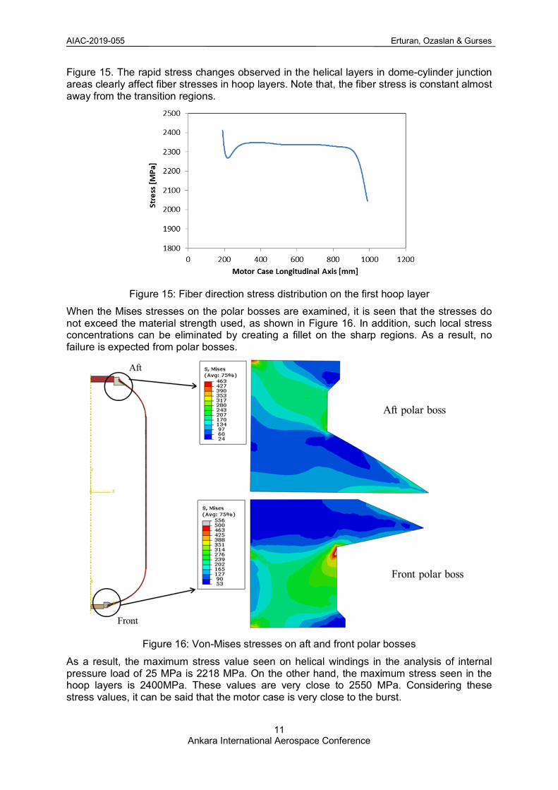
Figure 15. The rapid stress changes observed in the helical layers in dome-cylinder junction areas clearly affect fiber stresses in hoop layers. Note that, the fiber stress is constant almost away from the transition regions.
Figure 15: Fiber direction stress distribution on the first hoop layer
When the Mises stresses on the polar bosses are examined, it is seen that the stresses do not exceed the material strength used, as shown in Figure 16. In addition, such local stress concentrations can be eliminated by creating a fillet on the sharp regions. As a result, no failure is expected from polar bosses.
Figure 16: Von-Mises stresses on aft and front polar bosses
As a result, the maximum stress value seen on helical windings in the analysis of internal pressure load of 25 MPa is 2218 MPa. On the other hand, the maximum stress seen in the hoop layers is 2400MPa. These values are very close to 2550 MPa. Considering these stress values, it can be said that the motor case is very close to the burst.
AIAC-2019-055 Erturan, Ozaslan & Gurses
12 Ankara International Aerospace Conference
DOME PARAMETER STUDY Effect of Friction Coefficient The objective of the numerical solution method is to employ the couple of design variables {휆, 훼} which ensure a 90° fiber angle around the pole opening. The slippage tendency 휆 should belong to a predetermined applicable friction range [-0.5, 0.5]. It should also be considered that the slippage tendency 휆 can be negative. If 휆 is zero, the fibers follow the shortest path on the dome to form the geodesic dome profile, whereas non-geodesic dome profile is obtained when it is different than zero. Figure 17 shows that the non-geodesic based domes have a slightly larger volume and depth than the geodesic ones.
Figure 17: Effect of friction coefficient on the dome profile with the 0.5 opening ratio
Figure 18 shows the development of the winding angle in the domes for various 휆 values, ranging from 0 to 0.5. The results show that the fiber angle distribution has an overall decrease with an increase in slippage tendency.
Figure 18: Effect of friction coefficient on the winding angle distribution with the 0.5 opening
ratio
AIAC-2019-055 Erturan, Ozaslan & Gurses
13 Ankara International Aerospace Conference
Table 4 Values of design parameters for various friction coefficients λ
As the friction coefficient increases, the winding angle at the dome-cylinder conjunction region decreases, see Table 4. This reduces the thickness of the helical winding layer covering the entire body. Although the hoop winding thickness increases, the overall body weight will be reduced as the layers are applied only on the cylindrical region. The results show that the structural efficiency increases with increasing slippage tendency. It is also concluded that non-geodesic domes perform better than geodesic domes. Although the angle of winding reduces and the motor case performance increases, it should be remembered that the production method (wet or dry filament winding) should also be evaluated. The applicable coefficient of friction is highly dependent on the winding method. The dome profiles and winding angle distributions obtained in case of a negative coefficient of friction are shown in Figure 19 and Figure 20. In this case, it is clear that the negative slippage tendency is a more inefficient design. The main purpose of using a negative coefficient of friction in the design of motor case with different openings is to increase the winding angle in the dome cylinder region and to reduce the difference between the winding angle in the other dome-cylinder transition region. Thus, the angle change over the cylinder region will be less and the producibility will be increased.
Figure 19: Effect of negative friction coefficient on the dome profile with the 0.5 opening ratio
AIAC-2019-055 Erturan, Ozaslan & Gurses
14 Ankara International Aerospace Conference
Figure 20: Effect of negative friction coefficient on the winding angle distribution with the 0.5
opening ratio
CONCLUSION
The main purpose of this study is to provide a design method for composite rocket motor cases. Using the specified design method, the motor case is designed for a given burst pressure value while satisfying given geometric constraints. Due to the working conditions of the rocket motor case type pressure vessels, the netting theory is used in the composite case thickness calculations. A finite element analysis is carried out at the design pressure value and the body is found to maintain structural integrity at this pressure value. The netting approach is the easiest of the analytical methods applied in the design and evaluation of composite overwrapped tanks, but is sufficient for fiber winding pressure tanks. After verification of the design method and approach, the effect of slippage tendency is examined. Since the dome zones are the most sensitive places in terms of mechanical failure, the design of the domes is one of the most important aspects in a pressure tank design. Even though the profile differences between the geodesic and non-geodesic solutions are comparatively small, the existing design area has been adequately expanded in the design of non-geodesic approach. There is the possibility of changing the value of slippage tendency 휆 to give greater design freedom in determining winding trajectories. Furthermore, it was shown that the current approach based on non-geodesic winding can be very useful in the design phase of filament overwrapped pressure tanks with different dome openings. References
De Carvalho, J., Lossie, M., Vandepitte, D., and Van Brussel, H. (1995). Optimization of
Filament-Wound Parts Based on Non-geodesic Winding. Composites Manufacturing,
6(2), p: 79-84.
Denost, J. P. (1988). Design of Filament-Wound Rocket Cases. AGARD, Design Methods in
Solid Rocket Motors.
AIAC-2019-055 Erturan, Ozaslan & Gurses
15 Ankara International Aerospace Conference
Gray, A. (1993). Modern Differential Geometry of Curves and Surfaces. Boca Ration: CRC
press.
Koussios, S. (2002). Filament Winding: A unified approach.
Liang, C. C., Chen, H. W., & Wang, C. H. (2002). Optimum Design of Dome Contour for
Filament-Wound Composite Pressure Vessels Based On A Shape Factor. Composite
structures, 58(4), 469-482.
Peters, S. T. (Ed.). (2011). Composite filament winding. ASM International.
Schlichtkrull, H. (2012). Curves and Surfaces: Lecture Notes for Geometry 1. Department of
Mathematical Science, University of Copenhagen.
Vasiliev, V. V. (2009). Composite Pressure Vessels: Analysis, Design, and Manufacturing.
Bull Ridge Corporation.
Zu, L. (2012). Design and Optimization of Filament Wound Composite Pressure Vessels.
MSc. thesis report. Netherlands Box-Press.
Zu, L., Koussios, S., & Beukers, A. (2010). Design of Filament–Wound Domes Based on
Continuum Theory And Non-Geodesic Roving Trajectories. Composites Part A: Applied
Science and Manufacturing, 41(9), 1312-1320.
Zu, L., Koussios, S., & Beukers, A. (2010). Design of Filament-Wound Isotensoid Pressure
Vessels With Unequal Polar Openings. Composite Structures, 92(9), 2307-2313.