1 Structural Analysis- II Prof. P. Banerjee Department of Civil Engineering Indian Institute of Technology, Bombay Lecture – 31 Good morning. We have been discussing the displacement method and in the last few lectures I have established the basic concepts behind the displacement method. I had promised that we will spend about three to four lectures looking at various examples in the application of the displacement method. Today, we are going to be starting off by looking at one particular example. The kind of way I have chosen the examples has been essentially to establish the key principles of the application of the displacement method or actually the matrix displacement method which is the stiffness method as I had already stated. In the next few lectures, we are going to do that. Of course, it is impossible to do all types of problems, so I am only going to be taking up representative problems and along the way, I will illustrate a few detailed notes about the applications of displacement method, which I have not set up in the this thing, for example, how do we consider it if we have a support settlement? How do we consider temperature stresses in the displacement method or the stiffness method? I will be taking up all these things as examples as I go along during these particular few lectures, next few lectures. Let us start off with an example. (Refer Slide Time: 03:05) I am going to start off with simple examples and then go on to slightly more complicated examples. Let me take absolutely the simplest example, so this is the structure. This is EI, 4 meters (Refer Slide Time: 03:59) and this is 2 EI, 5 meters. This is the problem and here, the problem is essentially to figure out its displaced shape and also to figure out the bending moment, member end moments and bending moment diagram for this particular structure. First and foremost, how many degrees of freedom? I am going to just state it and I will expect you to
Transcript
1
Structural Analysis- II
Prof. P. Banerjee
Department of Civil Engineering
Indian Institute of Technology, Bombay
Lecture – 31
Good morning. We have been discussing the displacement method and in the last few lectures I
have established the basic concepts behind the displacement method. I had promised that we will
spend about three to four lectures looking at various examples in the application of the
displacement method. Today, we are going to be starting off by looking at one particular
example. The kind of way I have chosen the examples has been essentially to establish the key
principles of the application of the displacement method or actually the matrix displacement
method which is the stiffness method as I had already stated.
In the next few lectures, we are going to do that. Of course, it is impossible to do all types of
problems, so I am only going to be taking up representative problems and along the way, I will
illustrate a few detailed notes about the applications of displacement method, which I have not
set up in the this thing, for example, how do we consider it if we have a support settlement? How
do we consider temperature stresses in the displacement method or the stiffness method? I will
be taking up all these things as examples as I go along during these particular few lectures, next
few lectures. Let us start off with an example.
(Refer Slide Time: 03:05)
I am going to start off with simple examples and then go on to slightly more complicated
examples. Let me take absolutely the simplest example, so this is the structure. This is EI, 4
meters (Refer Slide Time: 03:59) and this is 2 EI, 5 meters. This is the problem and here, the
problem is essentially to figure out its displaced shape and also to figure out the bending
moment, member end moments and bending moment diagram for this particular structure. First
and foremost, how many degrees of freedom? I am going to just state it and I will expect you to
2
find this out. This is a two degrees of freedom structure; use the procedure that I have developed
and establish that these are two degrees of freedom. Of course, all of them are axially rigid. The
displacements are r1 and r2. Once we have those displacements, the next step is first to find out
the fixed end moments. Fixed end moments: this is a, b, c.
(Refer Slide Time: 05:36)
The fixed end moment for ab… the beam that I consider for ab is this one with this (Refer Slide
Time: 05:48) and due to this, you are going to have a (FEM)ba; the (FEM)ba is going to be equal
to 100… of course, the entire thing is minus, so 100 into 4 square divided by 12 plus half into
100 into 4 square upon 12 that is equal to... 3 by 2 is going to be equal to 108, if we look at this,
it is going to be 100 divided by 4, it is equal to 8 upon…. so it is going to be minus 8, 200 and
this is going to be 300 so this is going to be equal to minus 300 Kilonewton meter. (FEM)bc is
equal to (FEM)cb which is equal to 0, because there is no member force in this particular
member. Having done that, what happens is, the next step is going to be getting the displacement
pattern for each one, so let us have a look at that.
3
(Refer Slide Time: 08:42)
It is going to be r1 is equal to 1, this is going to go in this way, come like this – simple
displacement pattern that you have. If you look at it, what is thetaba equal to? Thetaba is equal to
0, thetabc is equal to 1 upon 5 from…, so that is positive 1 upon 5, thetacb is positive 1 upon 5,
then we have the rotation – the rotation is going to give me this (Refer Slide Time: 09:42), so this
is going to give me thetaba. This is r1 is equal to 1, this is r2 is equal to 1. thetaba is equal to 1,
thetabc is equal to 1 and thetacb is equal to 0.
(Refer Slide Time: 10:08)
Therefore, if we look at it, what we have is for member ab, a is going to be equal to 0, 1 and a for
member bc is going to be equal to (1 by 5, 1 by 5, 1, 0). What is a? If you look, it is essentially…
4
vi is equal to ai r, so here, what I have done is I have actually found out the two displacements the
two kinematic relationships: one that relates the member end rotation (Refer Slide Time: 11:01).
Note that since I have a modified member, I only have thetaba as my member rotation and the
relationship with the degrees of displacement corresponding to the degrees of freedom.
Having found out this, what do we have then? We know that Si, which in this case is Sab is
actually equal to Mba because Mab is equal to 0, is equal to… (Refer Slide Time: 12:06) this is a
transpose so it is going to be equal to 0, 1 into r1, r2 minus 300; Sbc, which is equal to (Mbc and
Mcb) is equal to this (Refer Slide Time: 12:43) into Kab. Note that Si is equal to Ki vi plus Si0. In
this particular case, the K is equal to 3EI by L and L in this particular case is 4; for this, the Mab
is equal to 4EI by L and 4EI, now EI is 2 EI, so this is going to be (8 EI upon 5 and 4EI by 5, 4EI
by 5, 8 EI by 5) into (1 upon 5, 1 upon 5, 1, 0) into (r1, r2) plus 0.
(Refer Slide Time: 14:19)
This is our relationship and ultimately using the virtual displacement, we can find out that capital
R is equal to sum of ai transpose Si; this is summed up over all the members (Refer Slide Time:
14:43) – plus summation over i ai (this I am going to put it as transpose) into ni – these are the
reaction terms that come from the member forces, the reactions only because those are not
considered in this specific thing. In this particular case, this will only exist for the summation ai
into ni. In this particular case it is only in ab, because that is the only member force that you have
and the reactions that you have for this particular case are 100 Kilonewton, which is 50 and 50
and if you look at these the work done by these 50, the aab transpose is actually equal to in both
the cases (0, 0, and 0, 0).
In other words, what we are really trying to find out is given r1 is equal to 1, how much does this
point (Refer Slide Time: 16:21) move up by and how much does this point move up by? If you
go back to the displacement pattern for r1 is equal to 1, how much does this point go up by? 0.
How much does this point go up by? 0. In this particular case, how much does this point go up
by? 0. How much does this point go up by? 0. That is essentially what you get over here.
5
Therefore in this particular case this term is equal to 0, because this is going to be equal to this
into your ni in this particular case are equal to 50 and 50, so that is equal to 0. Now, what we
need to do is essentially look at the other terms.
(Refer Slide Time: 17:23)
If you look at it, we get R equal to summation over i ai transpose Ki ai into r and the other term is
0. I need to find out for ab what is ai transpose Ki ai. Now, if you look at it, ai is equal to…. aab is
equal to (0, 1); Ki is equal to 3EI upon 4. Therefore, what we have here is since Ki is a scalar, I
can just do ai transpose into (0, 1) into 3EI upon 4 and if you look at that, that becomes (0, 0, 0,
1) 3EI by 4. Therefore, contribution of ab is equal to (0, 0, 0, 3EI by 4). Similarly, we can find
out for bc.
6
(Refer Slide Time: 19:11)
Kbc is going to be equal to abc transpose Kbc abc. Now, abc is equal to 4EI upon 5 into (2, 1, 1,
2)… that is Kbc and abc is equal to (1 by 5, 1 by 5, 1, 0). Therefore, the first thing is Kbc into abc
and this is equal to 4EI by 5 into (2, 1, 1, 2) into (1 by 5, 1 by 5, 1, 0) and this is going to be
equal to 4EI by 5; you have 2 by 5, so 3 by 5, here also you have 3 by 5, here you have 2, here
you have 1.
(Refer Slide Time: 20:36)
The next step is to find out Kbc. It is going to be equal to (1 by 5, 1 by 5, 1, 0) into 4EI upon 5
into (3 by 5, 3 by 5, 2, 1). This is going to be equal to 4EI by 5, this is going to be 3 by 25, 3 by
7
25, so it is going to be equal to 6 upon 25, this is going to be 3 upon 5, this is going to be 3 upon
5 and this is going to be 2. What is the total K?
(Refer Slide Time: 21:31)
The total K is going to be equal to 24 by 125, K is going to be equal to 24EI upon 125, this is
going to be 12 EI upon 125, this is going to be 12 EI upon 125 and this is going to be equal to EI
into 8 by 5 plus 3 by 4 – this is my K. Therefore, what is my R? If you look at R, R is going to be
equal to (50, 0) and we have not yet done the ai transpose into this thing and so the ai transpose
into Si0 is only there for ab and this is going to be equal to [0, 1] (Refer Slide Time: 22:53) into
minus 300, so this is going to be equal to 0, minus 300.
(Refer Slide Time: 23:15)
8
Ultimately, my equation looks like this. It is going to be (50, 0) is equal to (24EI upon 125, 12 EI
upon 125, 12 EI upon 125, 47 upon 20 EI) into (r1, r2) minus (0, 300). I can take this on this side,
so this implies that if I put EI outside, I get (24 upon 125, 12 upon 125, 12 upon 125, 47 upon
20) into (r1, r2) is equal to (50, 300). Therefore we solve this for r1 and r2 from which we can find
out our Si because it is equal to Ki ai into r. And once we find out the member end moments we
can always draw the bending moment diagram. This is a fairly simple specific problem and
therefore there is not too much in it.
Let me change this problem a little bit and then we can solve another problem with it, because
the essential thing that happens in this particular case is that we need to be able to find out how a
change can be incorporated in the entire problem statement. Let me change this problem and let
me give it as a slightly different problem and the problem that I will give you is this one – this is
another example.
(Refer Slide Time: 25:57)
Here, this is the same, excepting that now what I have done is I have now done this (Refer Slide
Time: 26:08), so this particular one that was vertical here – I have inclined it, this is same….
Here, you see this point can actually move in this direction, so instead of the horizontal, I am
going to define the vertical as my displacement degree of freedom – you can define it horizontal
also, there is no problem – this is 2 EI and this is still 4 meters, the only difference here is that
this is going to be equal to 3 meters and this is equal to 4 meters, so the total length is still 5
meters – it is just inclined. If we do that, what do you get?
9
(Refer Slide Time: 27:33)
The fixed end moment still remains the same and the fixed end moment is going to be equal to
100 multiplied by 4… and this (Refer Slide Time: 27:25) is going to be equal to 100 into 4 PL
upon 8, it is PL upon 8, this is minus plus half of PL upon 8; please make the correction even in
the previous problem so that instead of 300 what you have over here is minus 75 Kilonewton
meter; this is ba; please make the change that in the previous case also, this is minus; the same,
there is no difference in the fixed end moment.
In other words, by changing the structural configuration, the fixed end moments in the two
members are not changed. The only thing is that in the previous case when I had done minus 300
which is wrong: actually, what I had done was I had made a mistake, I had taken 100 to be the
intensity rather than a load; it is PL upon 8, so this is PL upon 8, half carryover from the other
side and therefore this is minus 75 and the frequencies are different.
10
(Refer Slide Time: 29:38)
Now, we come to the Ks. They are also the same. K of ab is equal to 3EI by 4 and Kbc is equal to
4EI by 5 – because EI is 2 EI – into (2, 1, 1, 2) – that is the stiffness for each member.
(Refer Slide Time: 30:05)
Now, we find out the as. For finding out a, what do I do? I have this and then I have this. Here, r1
is equal to 1. Now if you look at this, the only way this can move is along this line perpendicular
to this and therefore, for it to get 1 vertical, this will have to be 4 by 3 and this will have to be 5
by 3; therefore, this moves by 4 by 3, so this comes here and this 1 remains identical; this is
going to be like this and this is going to be like this; then, when I put r2 is equal to 1, I get the
11
same as in the previous case. Note that here, there is no moment restraint, so it can take any
arbitrary; here, this is equal to 1, this is equal to 1, this is r2 is equal to 1.
Therefore, we have aab is equal to.… If we look at the first one, the aab is equal to…. Let us take
stock of this: it is going to be like this (Refer Slide Time: 31:51) and this is going to be straight,
so this is going to be clockwise, so aab is going to be equal to 1 upon 4 and if you look at it, it is
going to be clockwise, so it is going to be minus 1 upon 4 and for this one, it is going to be equal
to 1. abc is going to be equal to… for the first one, the total displacement is 5 by 3 and if you look
at it, anticlockwise, so this is 5 by 3 divided by 5 is 1 by 3, so it is going to be 1 by 3, 1 by 3 and
for this one (Refer Slide Time: 32:45) it is going to be equal to (1, 0).
Note that we also need to find out in this particular case, how much does this point move by? I
am just going to do aab transpose which is to see how much these move up by (Refer Slide Time:
33:14), so these move up if you look at it, the aa is equal to 0 (this moves up by 0) and this
moves up by 1. If we look at it now, we have got the fixed end moments, we have got the Ks, we
have got the a’s and all we need to do now is to find out the contribution of each one.
(Refer Slide Time: 33:52)
I will write it down: Sab is equal to Ka into (minus 1 by 4, 1) into (r1, r2) plus if you look at this,
this is going to be minus 75 and Sbc is equal to 4EI upon 5 into (2, 1, 1, 2) into (1 over 3, 1 over
3, 1, 0) into (r1, r2) plus 0. This is Mbc and this is Mcb (Refer Slide Time: 35:40). This relationship
will come out to be important. Here, this part I will call as Tab and this part I will call as Tbc so
Tab is equal to minus 3EI by 16 and 3EI by 4.
In other words, this into the r1 r vector will give me Sab. Tbc becomes 4EI upon 5, in this two-
third plus one-third is equal to 1, here, you will have one-third and two-third, 1, this way you get
2, this way you get 1. This is Tab and Tbc.
12
(Refer Slide Time: 38:35)
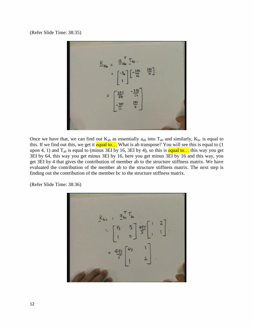
Once we have that, we can find out Kab as essentially aab into Tab and similarly, Kbc is equal to
this. If we find out this, we get it equal to… What is ab transpose? You will see this is equal to (1
upon 4, 1) and Tab is equal to (minus 3EI by 16, 3EI by 4), so this is equal to… this way you get
3EI by 64, this way you get minus 3EI by 16, here you get minus 3EI by 16 and this way, you
get 3EI by 4 that gives the contribution of member ab to the structure stiffness matrix. We have
evaluated the contribution of the member ab to the structure stiffness matrix. The next step is
finding out the contribution of the member bc to the structure stiffness matrix.
(Refer Slide Time: 38:36)
13
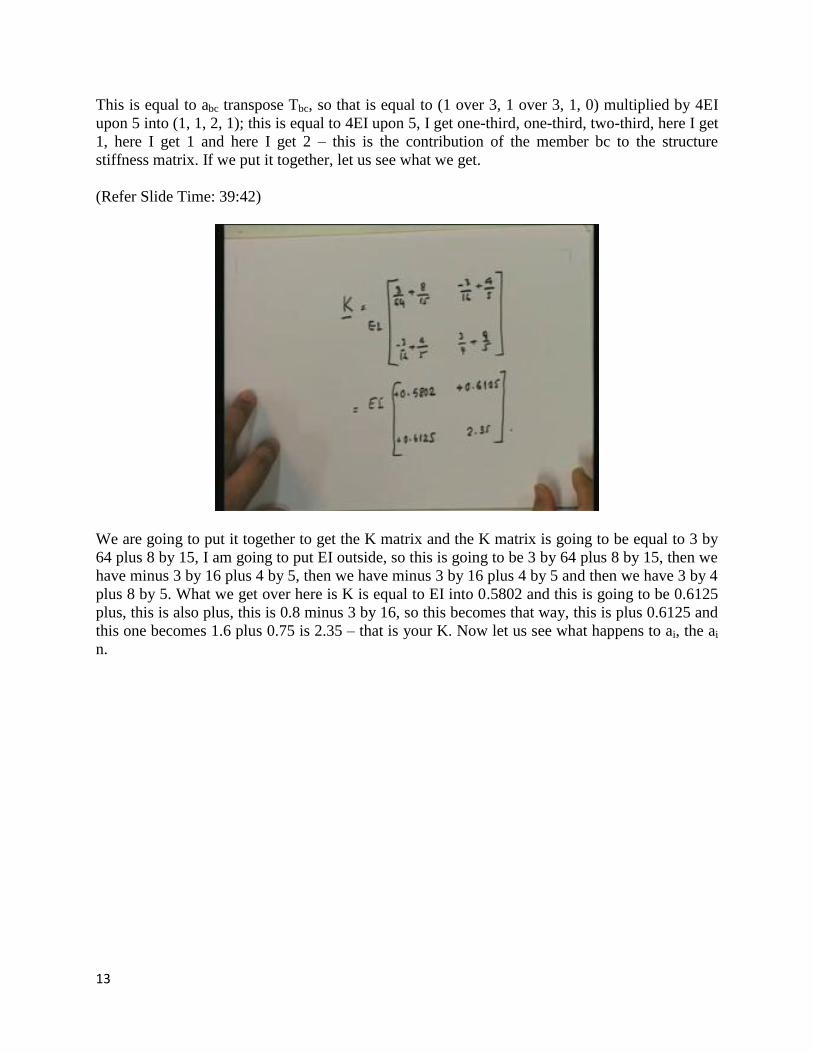
This is equal to abc transpose Tbc, so that is equal to (1 over 3, 1 over 3, 1, 0) multiplied by 4EI
upon 5 into (1, 1, 2, 1); this is equal to 4EI upon 5, I get one-third, one-third, two-third, here I get
1, here I get 1 and here I get 2 – this is the contribution of the member bc to the structure
stiffness matrix. If we put it together, let us see what we get.
(Refer Slide Time: 39:42)
We are going to put it together to get the K matrix and the K matrix is going to be equal to 3 by
64 plus 8 by 15, I am going to put EI outside, so this is going to be 3 by 64 plus 8 by 15, then we
have minus 3 by 16 plus 4 by 5, then we have minus 3 by 16 plus 4 by 5 and then we have 3 by 4
plus 8 by 5. What we get over here is K is equal to EI into 0.5802 and this is going to be 0.6125
plus, this is also plus, this is 0.8 minus 3 by 16, so this becomes that way, this is plus 0.6125 and
this one becomes 1.6 plus 0.75 is 2.35 – that is your K. Now let us see what happens to ai, the ai
n.
14
(Refer Slide Time: 41:59)
One part is computing aab into (Sab)0, which is the fixed end moment. If we do this part, aab
transpose is equal to (minus 1 over 4, 1) and Sab is equal to minus 75, so this is equal to on this
side 75 by 4 is 18.75 minus 75. This is one and the other one that we have is the work done by
the ai, so this is going to be aab transpose into (nab)0 and if you look at it what was aab? We had
computed aab, do you remember? We will just go back to that; that was equal to (0, 1), so this is
0, 1 and then 0, 0 – for r2 this is going to be 0, 0 so this multiplied by 50, 50 so what we get is
corresponding…, this is corresponding to the second one and this is 0, 0. So what we get over
here is that this is equal to 50 and this is equal to 0 (Refer Slide Time: 44:03).
(Refer Slide Time: 44:17)
15
Now, I am going to put everything together and so what I have over here is r which is 50, 0 is
equal to K; K is equal to EI into (0.5802, 0.6125, 0.6125, 2.35) into (r1, r2) plus (18.75, minus
75) plus (50, 0).
(Refer Slide Time: 45:24)
What we have over here is the fact that in this particular case, you will see that when I do on the
other side, I get it equal to EI into (0.5802, 0.6125, 0.6125, 2.35) into (r1, r2). I made a mistake
here – let us look at this. This is not 50. Why? Because even this one, I need to find out; my r1 is
my vertical, so the 50 is horizontal, so I need to find out how much this has moved by, so this is
going to be 4 by 3. When you have 4 by 3, you are going to have it equal to… this is going to be
equal to 50 by 3, minus 18 by 5, so this is going to be equal to minus, this is 68.5 and here, you
have 50 by 4, so this is equal to minus 50 by 3 minus 18 by 5, 50 by 3 is equal to 20, so this is
going to be equal to… just bear with me, 16.67, so this is going to be equal to 2.08 and this is
going to be 75.
We can solve, so r1 and r2 turns out to be equal to 1.0118 upon EI into (2.35, minus 0.6125,
minus 0.6125, 0.5802) into (minus 2.08, 75). If we do that computation, we get it equal to minus
51.434EI and this one works out to be 45.321 upon EI. We have got r1 and r2 and now if I am
going to plot this one, how would it look? r1 is negative which basically means that it actually
comes down and anticlockwise, so if I were to show that to you, it would look something like
this.
16
(Refer Slide Time: 49:09)
In other words this is of course exploded. This vertical (Refer Slide Time: 49:25) has actually
moved down; in other words, it cannot move down, it will have to move this way also, so this
point has actually come here where the vertical displacement is equal to 51.434 upon EI (Refer
Slide Time: 49:45). From that we can find out this displacement and furthermore this has rotated
in an anticlockwise manner. In other words, it has gone this way, so what we have over here is
this. This will have moved over here (Refer Slide Time: 50:13) by 4 by 3 times this, so this has
moved by 4 by 3 into 51.434 by EI, this is this distance, and this one is going to look like this.
This rotation from the horizontal is equal to 45.321 by EI and if you were to look at it from this,
this is also equal to this – from the original. This gives you the displaced shape of the structure.
Finally, once you have that, you can plug in the r1 and r2 values into the expressions and we get
Mba is equal to minus 31.365 Kilonewton, Mbc is equal to 31.365 and Mcb is equal to minus 4.89
Kilonewton meter.
17
(Refer Slide Time: 52:00)
The last part of this is to draw the bending moment diagram of this. We know the member end
moments, so this is clockwise; clockwise means this way so I am going to draw it on the tension
side, this would be this way (Refer Slide Time: 52:09) and this one if it is this way is this, this
one also goes here. We have 4.89, 31.365, the bending moment is in this way and then if we go
here, this is also 31.365 and here, we have 0, so we have this and then, I superpose on that the
100 so this I get this way and this way, this one is in this manner, this one is in this manner.
Therefore, what we have here is… this value you can check it will be equal to 84.32. This is the
bending moment diagram and that, in essence, is the complete solution of this method.
I have gone through all the steps in this particular case. I would like you to go back and revise
these steps so that you can be confident how to apply the displacement method. Thank you very