Page 468 Structural and Thermal Analysis of Steam Turbine Blade Using FEM Ruttala Bhargav M.Tech (Thermal) Student Department of Mechanical Engineering Adarsh College of Engineering Chebrolu, Kakinada. A.Rupesh Venkata Ramana Assistant Professor Department of Mechanical Engineering Adarsh College of Engineering Chebrolu, Kakinada. Dr. T. Dharma Raju Principal Department of Mechanical Engineering Adarsh College of Engineering Chebrolu, Kakinada. ABSTRACT In the present work the first stage rotor blade of a two-stage Steam turbine has been analyzed for structural, thermal using ANSYS 15, which is a powerful Finite Element Software. In the process of getting the static and thermal stresses, the fatigue life in the rotor blade has been improved using this software. The first stage rotor blade of the Steam turbine has been analyzed for the static and thermal stresses resulting from the tangential, axial and centrifugal forces. The Steam forces namely tangential, axial were determined by constructing velocity triangles at inlet and exist of rotor blades. The rotor blade was then analyzed for the temperature distribution. For obtaining temperature distribution, the convective heat transfer coefficients on the blade surface exposed to the Steam have to feed to the software. After containing the temperature distribution, the rotor blade was then analyzed for the combined mechanical and thermal stresses and also the fatigue life. Steam turbine is an important functional part of many applications. Reducing the stresses and increasing the fatigue life is the major concern since they are in high temperature environment. Various techniques have been proposed for the increase of fatigue life and one such technique is to have axial holes along the blade span. Finite element analysis is used to analyze thermal and structural performance due to the loading condition, with material properties of structural steel. Three different models with different size of holes (2, 3, and 4mm) were analyzed to find out the optimum number of holes for good performance. Graphs are plotted for stresses for existing design (7 holes) and for fatigue sensitivity against size of the holes (2, 3, and 4 mm). It is found that when the number of holes of the blades is increased, the stresses are reduced and number of cycles are increased. Thus, the blade configuration with 7 holes of 2mm size is found to be optimum solution. 1. INTRODUCTION Turbo machine rotor blades are subjected to different types of loading such as fluid or gas forces, inertia loads and centrifugal forces. Due to these forces various stresses are induced in rotor blades. So stress and strain mapping on a rotor blade provide a vital information concerning the turbo machine design and lead to the detection of critical blade section. Analysis
Transcript
Page 468
Structural and Thermal Analysis of Steam Turbine Blade Using
FEM
Ruttala Bhargav
M.Tech (Thermal) Student
Department of Mechanical
Engineering
Adarsh College of Engineering
Chebrolu, Kakinada.
A.Rupesh Venkata Ramana
Assistant Professor
Department of Mechanical
Engineering
Adarsh College of Engineering
Chebrolu, Kakinada.
Dr. T. Dharma Raju
Principal
Department of Mechanical
Engineering
Adarsh College of Engineering
Chebrolu, Kakinada.
ABSTRACT
In the present work the first stage rotor blade of a
two-stage Steam turbine has been analyzed for
structural, thermal using ANSYS 15, which is a
powerful Finite Element Software. In the process of
getting the static and thermal stresses, the fatigue life
in the rotor blade has been improved using this
software.
The first stage rotor blade of the Steam turbine has
been analyzed for the static and thermal stresses
resulting from the tangential, axial and centrifugal
forces. The Steam forces namely tangential, axial
were determined by constructing velocity triangles at
inlet and exist of rotor blades. The rotor blade was
then analyzed for the temperature distribution. For
obtaining temperature distribution, the convective
heat transfer coefficients on the blade surface
exposed to the Steam have to feed to the software.
After containing the temperature distribution, the
rotor blade was then analyzed for the combined
mechanical and thermal stresses and also the fatigue
life.
Steam turbine is an important functional part of
many applications. Reducing the stresses and
increasing the fatigue life is the major concern since
they are in high temperature environment. Various
techniques have been proposed for the increase of
fatigue life and one such technique is to have axial
holes along the blade span. Finite element analysis is
used to analyze thermal and structural performance
due to the loading condition, with material properties
of structural steel.
Three different models with different size of holes (2,
3, and 4mm) were analyzed to find out the optimum
number of holes for good performance. Graphs are
plotted for stresses for existing design (7 holes) and
for fatigue sensitivity against size of the holes (2, 3,
and 4 mm). It is found that when the number of holes
of the blades is increased, the stresses are reduced
and number of cycles are increased. Thus, the blade
configuration with 7 holes of 2mm size is found to be
optimum solution.
1. INTRODUCTION
Turbo machine rotor blades are subjected to different
types of loading such as fluid or gas forces, inertia
loads and centrifugal forces. Due to these forces
various stresses are induced in rotor blades. So stress
and strain mapping on a rotor blade provide a vital
information concerning the turbo machine design and
lead to the detection of critical blade section. Analysis
ss
Stamp
ss
Stamp
Page 469
of static and dynamic behavior of a rotor blade is a
basic problem in aero elasticity of turbo machine
blades. The present paper deals with the stress analysis
of a typical blade made up of nickel super alloy, which
is subjected to centrifugal loading. The analysis results
shows that stress is sever due to centrifugal forces
compared that due to dynamic gas forces. Here in this
case the effect of thickness, twist and taper of the blade
was considered at the root of the blade where generally
failure is occurring. The various blade shapes viz.
rectangular, aerofoils with some angle twist, taper
aerofoil are taken into consideration. In this paper
linear static analysis for determining von-mises
stresses, deformation in Z direction was determined
using Finite element analysis software. The Solid brick
20-node element is used.
Aero engine turbine and compressor blades operate at
speed range 5000 to 15000 r.p.m with temperature
ranging from 50 to 900 degree centigrade. Hence
depending on the stage of operation, blade material is
usually an AL alloy, stainless steels, titanium alloys
and nickel-based alloys. The tolerances on the blades
are usually in the range of 0.05 mm to 0.15 mm on the
aerofoil. The blades have a complex aerofoil structure
and with varying aerofoil shape at different sections
along the length of blade. There is always a twist in the
aerofoil sometimes of the order 60 degrees. These
complex configurations are required as the gases are to
be smoothly guided along the different stages of the
compressor and turbine without turbulence to achieve
maximum thrust from the engine. Fatigue failure
result from a combination of steady stress, vibratory
stress, and material imperfections. However, the size
of microscopic imperfections is difficult to control.
Hence, stress-range diagrams are used to quantify the
allowable vibratory stress amplitudes to avoid fatigue
damage. Advanced turbo machinery blading is
designed to have high steady stress levels. Thus, HCF
occurs because of high mean stress - low amplitude
vibratory loading of the airfoils. It is often initiated by
the formation of small microscopic cracks.
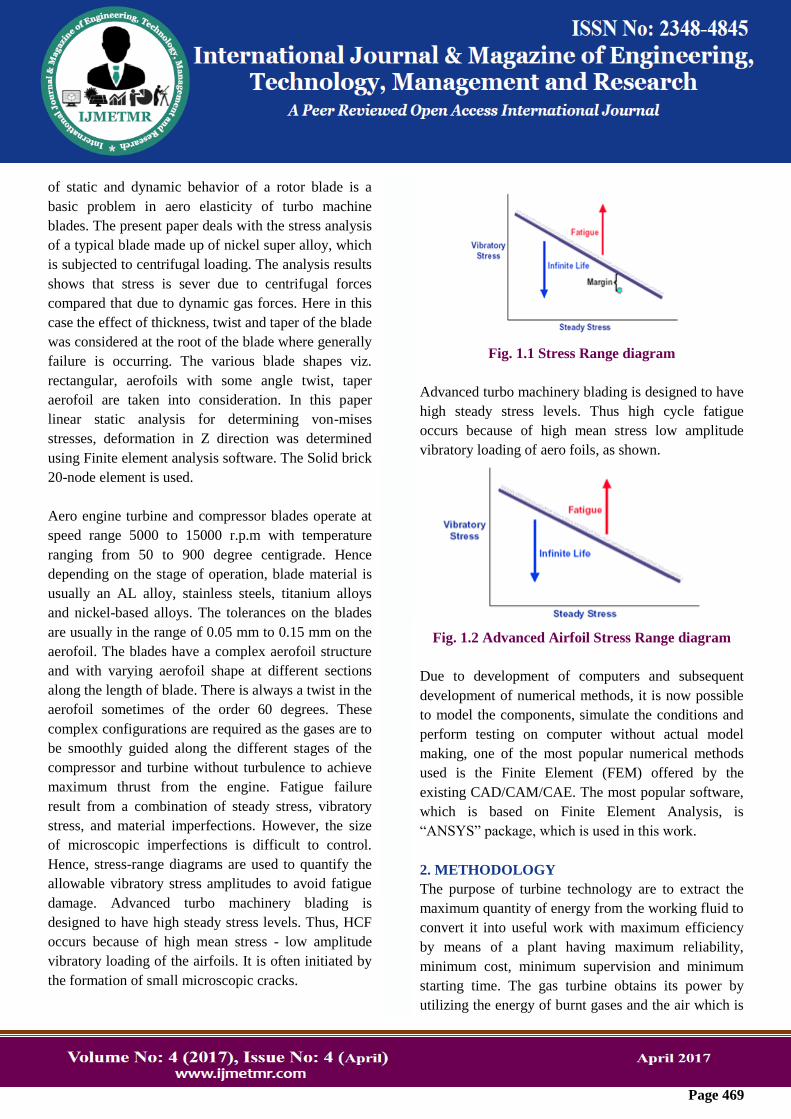
Fig. 1.1 Stress Range diagram
Advanced turbo machinery blading is designed to have
high steady stress levels. Thus high cycle fatigue
occurs because of high mean stress low amplitude
vibratory loading of aero foils, as shown.
Fig. 1.2 Advanced Airfoil Stress Range diagram
Due to development of computers and subsequent
development of numerical methods, it is now possible
to model the components, simulate the conditions and
perform testing on computer without actual model
making, one of the most popular numerical methods
used is the Finite Element (FEM) offered by the
existing CAD/CAM/CAE. The most popular software,
which is based on Finite Element Analysis, is
“ANSYS” package, which is used in this work.
2. METHODOLOGY
The purpose of turbine technology are to extract the
maximum quantity of energy from the working fluid to
convert it into useful work with maximum efficiency
by means of a plant having maximum reliability,
minimum cost, minimum supervision and minimum
starting time. The gas turbine obtains its power by
utilizing the energy of burnt gases and the air which is
ss
Stamp
ss
Stamp
ss
Stamp
Page 470
at high temperature and pressure by expanding through
the several rings of fixed and moving blades. To get a
high pressure of order 4 to 10 bar of working fluid,
which is essential for expansion a compressor, is
required. The quantity of ten working fluid and speed
required are more so generally a centrifugal or axial
compressor is required. The turbine drives the
compressor so it is coupled to the turbine shaft. If after
compression the working fluid were to be expanded in
a turbine, then assuming that there were no losses in
either component, the power developed by the turbine
can be increased by increasing the volume of working
fluid at constant pressure or alternatively increasing
the pressure at constant volume. Either of these may be
done by adding heat so that the temperature of the
working fluid is increased after compression. To get a
higher temperature of the working fluid a combustion
chamber is required where combustion of air and fuel
takes place giving temperature rise to the working
fluid.
Fig.2.1 Turbine Blade Coupled to Centrifugal
Compressor
WHAT IS THE SOLUTION?
In the solution phase of the analysis, the computer
takes over and solves the simultaneous equations that
the finite element method generates. The results of the
solution are:
a) Nodal degree of freedom values which form the
primary solution and
b) derived values, which form the element solution.
The element solution is usually calculated at the
element integration points.
Several methods of solving the simultaneous equations
are available in the ANSYS program, frontal solution,
sparse direction solution, Jacobi Conjugate Gradient
solution, Precondition Conjugate Solution and an
automatic iteration solver option. The frontal solver is
the default.
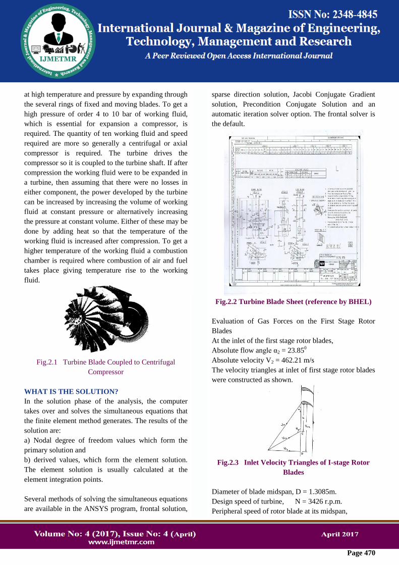
Fig.2.2 Turbine Blade Sheet (reference by BHEL)
Evaluation of Gas Forces on the First Stage Rotor
Blades
At the inlet of the first stage rotor blades,
Absolute flow angle α2 = 23.850
Absolute velocity V2 = 462.21 m/s
The velocity triangles at inlet of first stage rotor blades
were constructed as shown.
Fig.2.3 Inlet Velocity Triangles of I-stage Rotor
Blades
Diameter of blade midspan, D = 1.3085m.
Design speed of turbine, N = 3426 r.p.m.
Peripheral speed of rotor blade at its midspan,
ss
Stamp
ss
Stamp
Page 471
U = πDN/60 ……………(1)
From the velocity triangles in Fig. we get,
Whirl velocity Vw2 = 422.74 m/s
Flow Velocity Vf2 = 186.89 m/s
Relative velocity Vr2 = 265.09 m/s
Blade angle at inlet θ2 = 135.017 0
At the exit of first stage rotor blades,
Flow velocity Vf3 = 180.42 m/s
Relative flow angle θ2 = 37.88 0
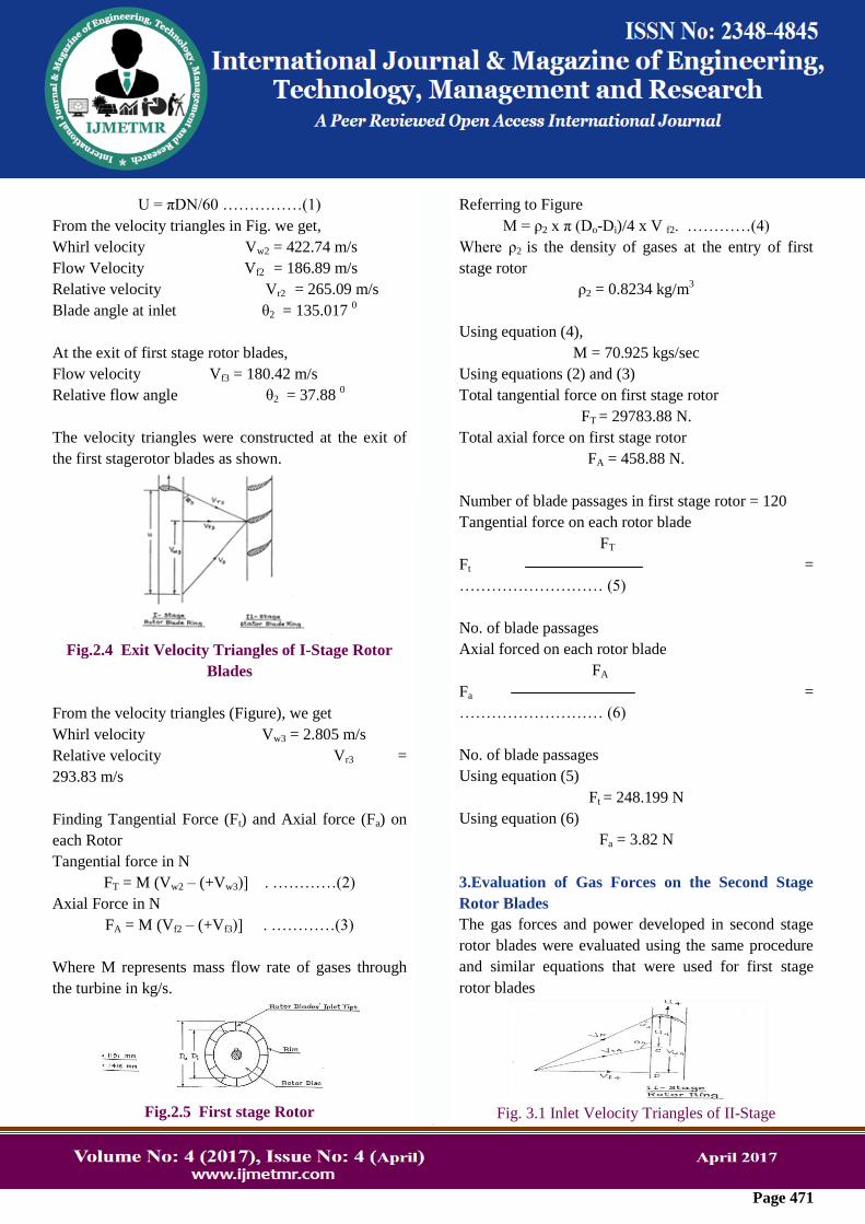
The velocity triangles were constructed at the exit of
the first stagerotor blades as shown.
Fig.2.4 Exit Velocity Triangles of I-Stage Rotor
Blades
From the velocity triangles (Figure), we get
Whirl velocity Vw3 = 2.805 m/s
Relative velocity Vr3 =
293.83 m/s
Finding Tangential Force (Ft) and Axial force (Fa) on
each Rotor
Tangential force in N
FT = M (Vw2 – (+Vw3)] . …………(2)
Axial Force in N
FA = M (Vf2 – (+Vf3)] . …………(3)
Where M represents mass flow rate of gases through
the turbine in kg/s.
Fig.2.5 First stage Rotor
Referring to Figure
M = ρ2 x π (Do-Di)/4 x V f2. …………(4)
Where ρ2 is the density of gases at the entry of first
stage rotor
ρ2 = 0.8234 kg/m3
Using equation (4),
M = 70.925 kgs/sec
Using equations (2) and (3)
Total tangential force on first stage rotor
FT = 29783.88 N.
Total axial force on first stage rotor
FA = 458.88 N.
Number of blade passages in first stage rotor = 120
Tangential force on each rotor blade
FT
Ft =
……………………… (5)
No. of blade passages
Axial forced on each rotor blade
FA
Fa =
……………………… (6)
No. of blade passages
Using equation (5)
Ft = 248.199 N
Using equation (6)
Fa = 3.82 N
3.Evaluation of Gas Forces on the Second Stage
Rotor Blades
The gas forces and power developed in second stage
rotor blades were evaluated using the same procedure
and similar equations that were used for first stage
rotor blades
Fig. 3.1 Inlet Velocity Triangles of II-Stage
ss
Stamp
ss
Stamp
ss
Stamp
Page 472
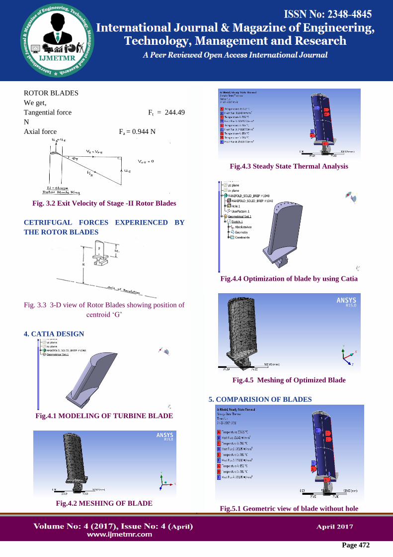
ROTOR BLADES
We get,
Tangential force Ft = 244.49
N
Axial force Fa = 0.944 N
Fig. 3.2 Exit Velocity of Stage -II Rotor Blades
CETRIFUGAL FORCES EXPERIENCED BY
THE ROTOR BLADES
Fig. 3.3 3-D view of Rotor Blades showing position of
centroid „G‟
4. CATIA DESIGN
Fig.4.1 MODELING OF TURBINE BLADE
Fig.4.2 MESHING OF BLADE
Fig.4.3 Steady State Thermal Analysis
Fig.4.4 Optimization of blade by using Catia
Fig.4.5 Meshing of Optimized Blade
5. COMPARISION OF BLADES
Fig.5.1 Geometric view of blade without hole
ss
Stamp
ss
Stamp
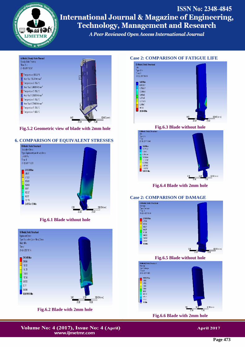
Page 473
Fig.5.2 Geometric view of blade with 2mm hole
6. COMPARISON OF EQUIVALENT STRESSES
Fig.6.1 Blade without hole
Fig.6.2 Blade with 2mm hole
Case 2: COMPARISON OF FATIGUE LIFE
Fig.6.3 Blade without hole
Fig.6.4 Blade with 2mm hole
Case 2: COMPARISON OF DAMAGE
Fig.6.5 Blade without hole
Fig.6.6 Blade with 2mm hole
ss
Stamp
ss
Stamp
ss
Stamp
Page 474
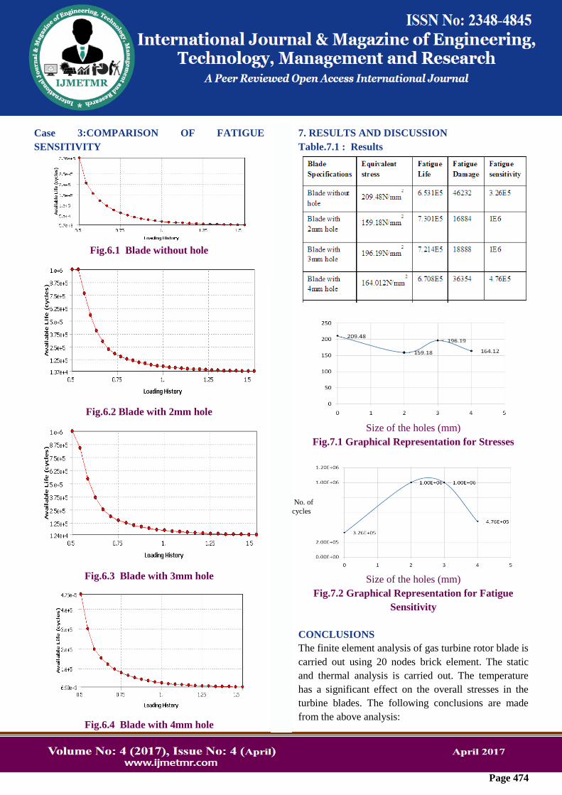
Case 3:COMPARISON OF FATIGUE
SENSITIVITY
Fig.6.1 Blade without hole
Fig.6.2 Blade with 2mm hole
Fig.6.3 Blade with 3mm hole
Fig.6.4 Blade with 4mm hole
7. RESULTS AND DISCUSSION
Table.7.1 : Results
Size of the holes (mm)
Fig.7.1 Graphical Representation for Stresses
Size of the holes (mm)
Fig.7.2 Graphical Representation for Fatigue
Sensitivity
CONCLUSIONS
The finite element analysis of gas turbine rotor blade is
carried out using 20 nodes brick element. The static
and thermal analysis is carried out. The temperature
has a significant effect on the overall stresses in the
turbine blades. The following conclusions are made
from the above analysis:
No. of
cycles
ss
Stamp
ss
Stamp
ss
Stamp
Page 475
1. Stress obtained for the turbine blade without holes is
209.48N/mm2
2. When the size of the hole is 2mm stress obtained is
159.18N/mm2
therefore stresses are reduced by
50N/mm2
3. For blade with 3mm hole stress increased by
37N/mm2 whereas for the blade with 4mm holes stress
results were quite different, it decreased by 35N/mm2
4. The no. of cycles for blade without hole is 3.26 x
105, for blade with 2mm and 3mm hole no. of cycles
remains constant i.e. 106
whereas for 4mm blade its
4.76 x 10⁵
5. Stress are reduced and fatigue life increased for
blades with holes
6. On the whole it is noticed that the equivalent
stresses are reduced up to 23% for the blades with
holes as compared to blade without holes
Thus blade with 2mm hole is better for suing because
the stress obtained is less and the number of cycles
increased when compared to blades with 2, 3and 4mm
holes.
REFERENCE
1. Xiaoping Qian, Deba Dutta (2001) Design of
heterogeneous Turbine blade vol.35 pg(319-329)
2. Mehdi Tofighi Naeem, Seyed Ali Jazayeri, Nesa
Rezamahdi (2005) Failure Analysis of Gas Turbine
Blades. Paper 120, ENG 108
3. P.Dhopade, A.J. Neely (2010) Fluid-structure
interaction of Gas Turbine Blades vol.17 pg(5-9)
4. W.P.Parks, E.E.Hoffman, W.Y.Lee, and I.G. Wright
(1997) Thermal Barrier Coatings Issues in Advanced