TRANSPORTATION RESEARCH RECORD 1223 107 Structural Applications of Composite Materials to Highway Tunnels CHARLES E. KAEMPEN Highway tunnels constructed of concrete enclosed by a double- wall tubular composite structure are shown to be economically feasible and merit serious attention by planners of advanced trans- portation methods that must contend with water crossings. Mod- ern techniques for mechanically coupling and sealing tubular com- posite structures are shown to now enable composite materials to compete with welded steel joints in strength and long-term service. Engineering properties and commercial applications of the new class of twined-strand unidirected composite materials are pre- sented along with cost and performance comparisons between com- posites and identical pipe and tank structures made of steel. A detailed engineering solution to the problem of providing an affordable fixed transportation link between Europe and Africa across the Strait of Gibraltar is presented. This example shows how structural composites can be used with concrete to fabricate the type of highway tunnel envisioned as an inevitable adjunct to conventional approaches used to solve current and future trans- portation problems. Unidirected twined-strand composites comprise a new class of composite materials that are less expensive to fabricate into highway tunnel structures than equivalent strength structures made of carbon steel. Modern techniques for mechanically coupling and sealing tubular composite structures now enable composite materials to compete with welded steel joints in strength and long-term service. Tubular double-wall com- posite structures now provide an alternate method of forming and reinforcing concrete highway tunnels and culverts. Com- bining the exceptional tensile strength and corrosion resist- ance of unidirected composite material with the compressive strength and formability of concrete provides a new approach to the construction and installation of future highway tunnels. CHARACTERISTICS OF COMMERCIAL COMPOSITES There is a continuing trend among engineers, architects, and developers to replace steel structures with structures made from commercial composite material. One of the principal reasons is that structures made from commercial composite material do not deteriorate from weathering or corrosion and thus require less maintenance. Another reason is that they are safer and less expensive to transport and install because of their lower weight. Unlike steel, commercial composite materials will not experience failure because of structural fatigue caused by repeated flexure under stress. Commercial composite materials are fracture resistant and have incredible energy-absorbing characteristics. Commercial Kaempen & Associates, Consulting Engineers, 3202 Larkstone Drive, Orange, Calif. 92669. composites are 100 times more thermally insulative than steel and thus are a safer structural material because they do not weaken as rapidly when exposed to fire. Today, special inex- pensive inorganic polymers can be employed as the glass- filament impregnating matrix to provide noncombustible commercial composites that can remain structurally compe- tent when exposed for extended durations to temperatures as high as 2,000°F. These new noncombustible high-temperature structural composites do not produce toxic smoke or gases when exposed to fire. Commercial composites are also elec- trically insulative and can be made to be either translucent or opaque. Commercial composites are the most versatile structural material available. The term commercial composites is used to refer to unidi- rected high-strength composites made from continuous strands of glass fiber and to distinguish them from aerospace com- posites, which are unidirected composites made from carbon or aramid fibers. Aerospace composites, such as those used by Burt Rutan to build the Voyager aircraft, which flew non- stop around the world, cost at least 10 times more than com- mercial composites having the same weight. Aerospace com- posites can be as stiff as steel while having a density lower than magnesium. Both aerospace composites and commercial composites are several times stronger than steel. The recent development of twined-strand composites has now made it possible to make composite couplers that can mechanically join commercial composites so that the joint strength at least equals the maximum tensile strength of the composite laminar structure being connected. Figure 1 sum- marizes the result of ASTM Procedure A cyclic pressure tests (ASTM D2992) performed on specimens of reinforced ther- mosetting resin pipe (RTRP) made from twined-strand com- posite material. These tests demonstrate that the hydrostatic design basis strength (HDBS) of the twined strand composite material exceeds 60,000 lb/sq in., a value approximately three times higher than the maximum allowable design strength of steels used to make pipe conforming to the ASME B31.3 code for pressure piping. CHARACTERISTICS OF TWINED-STRAND COMPOSITES Twined-strand composites are a new class of unidirected com- posites that comprise helically twisted strands of continuous filament reinforcement. Figure 2 illustrates the composite twine structure disclosed in recent U.S. and world patents awarded to the author (U.S. Patent Nos. 4,680,923 and 4,740,422). Figure 3 illustrates the construction of a high-strength mechanical coupler made from twined-strand composites.
Transcript
TRANSPORTATION RESEARCH RECORD 1223 107
Structural Applications of Composite Materials to Highway Tunnels
CHARLES E. KAEMPEN
Highway tunnels constructed of concrete enclosed by a doublewall tubular composite structure are shown to be economically feasible and merit serious attention by planners of advanced transportation methods that must contend with water crossings. Modern techniques for mechanically coupling and sealing tubular composite structures are shown to now enable composite materials to compete with welded steel joints in strength and long-term service. Engineering properties and commercial applications of the new class of twined-strand unidirected composite materials are presented along with cost and performance comparisons between composites and identical pipe and tank structures made of steel. A detailed engineering solution to the problem of providing an affordable fixed transportation link between Europe and Africa across the Strait of Gibraltar is presented. This example shows how structural composites can be used with concrete to fabricate the type of highway tunnel envisioned as an inevitable adjunct to conventional approaches used to solve current and future transportation problems.
Unidirected twined-strand composites comprise a new class of composite materials that are less expensive to fabricate into highway tunnel structures than equivalent strength structures made of carbon steel. Modern techniques for mechanically coupling and sealing tubular composite structures now enable composite materials to compete with welded steel joints in strength and long-term service. Tubular double-wall composite structures now provide an alternate method of forming and reinforcing concrete highway tunnels and culverts. Combining the exceptional tensile strength and corrosion resistance of unidirected composite material with the compressive strength and formability of concrete provides a new approach to the construction and installation of future highway tunnels.
CHARACTERISTICS OF COMMERCIAL COMPOSITES
There is a continuing trend among engineers, architects, and developers to replace steel structures with structures made from commercial composite material. One of the principal reasons is that structures made from commercial composite material do not deteriorate from weathering or corrosion and thus require less maintenance. Another reason is that they are safer and less expensive to transport and install because of their lower weight. Unlike steel, commercial composite materials will not experience failure because of structural fatigue caused by repeated flexure under stress.
Commercial composite materials are fracture resistant and have incredible energy-absorbing characteristics. Commercial
composites are 100 times more thermally insulative than steel and thus are a safer structural material because they do not weaken as rapidly when exposed to fire. Today, special inexpensive inorganic polymers can be employed as the glassfilament impregnating matrix to provide noncombustible commercial composites that can remain structurally competent when exposed for extended durations to temperatures as high as 2,000°F. These new noncombustible high-temperature structural composites do not produce toxic smoke or gases when exposed to fire. Commercial composites are also electrically insulative and can be made to be either translucent or opaque. Commercial composites are the most versatile structural material available.
The term commercial composites is used to refer to unidirected high-strength composites made from continuous strands of glass fiber and to distinguish them from aerospace composites, which are unidirected composites made from carbon or aramid fibers. Aerospace composites, such as those used by Burt Rutan to build the Voyager aircraft, which flew nonstop around the world, cost at least 10 times more than commercial composites having the same weight. Aerospace composites can be as stiff as steel while having a density lower than magnesium. Both aerospace composites and commercial composites are several times stronger than steel.
The recent development of twined-strand composites has now made it possible to make composite couplers that can mechanically join commercial composites so that the joint strength at least equals the maximum tensile strength of the composite laminar structure being connected. Figure 1 summarizes the result of ASTM Procedure A cyclic pressure tests (ASTM D2992) performed on specimens of reinforced thermosetting resin pipe (RTRP) made from twined-strand composite material. These tests demonstrate that the hydrostatic design basis strength (HDBS) of the twined strand composite material exceeds 60,000 lb/sq in., a value approximately three times higher than the maximum allowable design strength of steels used to make pipe conforming to the ASME B31.3 code for pressure piping.
CHARACTERISTICS OF TWINED-STRAND COMPOSITES
Twined-strand composites are a new class of unidirected composites that comprise helically twisted strands of continuous filament reinforcement. Figure 2 illustrates the composite twine structure disclosed in recent U.S. and world patents awarded to the author (U.S. Patent Nos. 4,680,923 and 4,740,422). Figure 3 illustrates the construction of a high-strength mechanical coupler made from twined-strand composites.
LOG HOOP STRESS 4.98
4.9S
4.94
4.92
4.90
4.88
4.BS
4.84
4.82
4.80
ps I ( S20. 7 MP al
73,000 psi (503.5
CAFTER 1,000,000
SS, 000 ps li-""""( AFTER 15,000,000 CYCLES> ' ...
FIGURE 1 Plot of stress versus cycles resulting from ASTM D2992 cyclic tests of composite pipe made from twined strands of glass fiber.
FIGURE 2 Enlarged view of unidirected twined·strand composite structure defined by sine wave frequency of strand twining.
HALF
COUPLER SLEEVE
HALF COUPLER
FIGURE 3 Exploded view of a high·strength composite coupler and seal assembly.
Kaempen
Tubular-shaped twined-strand composite structures take less time to manufacture than tubular composite structures made by conventional filament winding processes. This is one reason twined-strand composite structures are less expensive to manufacture than other composite structures. In addition to providing a superior method of being structurally connected, twined-strand composites are also stiffer than conventional multi-ply composite laminates.
Tubular structures made from twined composite material may comprise as few as two plies: an inner ply of circumferentially oriented twines (CIRC) surmounted by an outer ply of longitudinally oriented twines (LONGO). The inner ply of CIRC twines is primarily employed to resist the radially directed hoop stresses produced by pressure or compressive loads. The outer ply of LONGO twines is primarily employed to resist longitudinally directed tensile and compressive stresses such as those produced by bending or pulling. The outer ply composite twine structure is configured as a flared-end laminate that comprises the flanged-end portion of a tubular composite structure, which can be mechanically connected by a composite coupler assembly.
Figure 4 illustrates composite pressure pipe connected by this unique high-strength coupling. Figures 5 and 6 illustrate a cross section view of the structural configuration and of a typical tubular twined composite structure connected and sealed with a high-strength composite coupling. Figure 7 shows a typical installation of a high-pressure petroleum pipeline mechanically connected by a two-piece composite coupler and coupler retaining sleeve. Such mechanically connected composite pressure pipe with removable end plugs have been hydrostatically tested repeatedly at pressures as great as 10,000 psi without leakage or structural failure. Such pipe has been thoroughly tested to meet the structural requirements established for fiberglass pressure vessels by ASME Section X of the boiler and pressure vessel code and for nonmetallic pipe established by the ASME B31.3 and B31.4 pipe codes. The high-pressure mechanically coupled composite pressure pipe illustrated in Figure 8 has been made and sold by U.S. and Canadian licensees since April 1982.
Table 1 presents the physical properties of a single composite ply made of unidirected twines of continuous strands of glass filaments.
COST AND CONNECT ABILITY COMPARISONS: COMPOSITES VERSUS STEEL
109
Primary load-bearing structures made from commercial composites can today be designed to be competitive in cost with equivalent structures made of steel or reinforced concrete. Commercial composites made from glass roving and polyester resin today sell for approximately $3.00/lb and cost approximately $2.00/lb. Glass roving and polyester resin cost less than $0.90/lb when purchased in quantity. Commercial composites made from twined strands of glass roving impregnated with polyester resin possess the physical properties shown in Table 1.
To illustrate the fact that, as a primary load-bearing structural material, commercial composites now compete in cost with steel, a comparison of pipe material costs is presented. The maximum allowable design strength of steel used to make pipe that meets the ASME B-31 pipe code requirements is 20,000 psi (138 MPa). This is only one-third the allowable design strength of commercial composites, which, as can be seen from Table 1, possess an HDBS of 60,000 psi as determined from cyclic test results (ASTM D2992A).
The current sale price of steel pipe is not less than $0.40/ lb when purchased in multiton shipments. Because 1 lb of commercial composite material equals the structural performance of 12 lb of steel, at least $4.80 worth of steel will be required to perform as well as 1 lb of commercial composite material selling for $3.00/lb. Of course, cost versus strength comparisons reflect only part of the picture. Reliability as an end use structure also depends on the ease and reliability of joining and sealing the structural materials . Until the recent advent of high-strength composite mechanical couplers, one of the principal advantages of using steel instead of composite material as a structural material was that steel could be structurally connected without any sacrifice in structural strength. Conventional composite structures comprising a multitude of overlapping laminate plies cannot be connected without a substantial sacrifice in structural strength. This is because when conventional composites are connected the joint strength is no greater than the strength of the matrix or bonding adhesive. Composite matrix materials possess only one-tenth of the strength of the composite filament reinforcements.
FIGURE 4 Photographic section detail of sealed and coupled composite pipe.
110
FIGURE 5 Section detail of a high-tensile-strength composite coupler and seal assembly.
COMPOSITE COUPLING SLEEVE
SEAL RING 1CMAXIMUM COMPRESSION! I
' ' '
I I I I I
COMPOSITE PIPE ENDt CMAX. PIPE ELONGATl~Nl
I I I I I I I I I I I
COMPOSITE HALF-COUPLER CTWO REQ'Dl
FIGURE 6 Section view showing how coupled pipe thermal expansion can be accommodated by composite coupler assembly.
By using the new high-strength twined-strand composite couplers, tubular composite structures can now be connected quickly and reliably to exhibit the same joint strength and sealing integrity as a welded steel structure of the same wall thickness.
STRUCTURAL APPLICATIONS OF COMMERCIAL COMPOSITES
Because of the widespread engineering experience gained by using commercial composites as primary load-bearing structures, the time has come to begin planning and constructing highway tunnels, bridges, and underroad culverts that use this amazingly versatile and cost-effective structural material.
The reliability and effectiveness of glass-reinforced polymeric resin composite material has been demonstrated in numerous applications. For example, the U.S. Navy selected this material for use in constructing the forward portion of
TRANSPORTATION RESEARCH RECORD 1223
FIGURE 7 Photograph of a 6-in.-diameter mechanically coupled 3,000 psi pressure pipe.
the 30-ft-diameter Trident submarine. Minesweepers and other ships made of this material have been in service for over 10 years. Bridges in China and Germany made of glass-polyester composites are already in service. Large-diameter chimney liners and free-standing chimneys that resist corrosion have been in service for many years.
In 1982 a 40-ft-diameter, 45-ft-high fuel storage tank that met the National Fire Protection Association requirements for aboveground storage of flammable liquids (NFP A 30) was constructed entirely of commercial composites at Aransas Pass, Texas. This structure was constructed on the job site despite high winds, frequent rainstorms , blistering heat, and high humidity. The structure was thoroughly tested before being placed into service.
This tank was constructed as a double-wall tank. The inner tank composite material was selected on the basis of strength and compatibility with water or petroleum products. The outer tank and rib structure was made of a noncombustible composite material that could resist long-term exposure to fire, as well as the wind and weather present in the area.
Figures 9 through 11 illustrate how this tank was built and how it appeared on completion. The tank incorporated an internal floating roof to control vapor emission, as well as a fixed roof to prevent rain and dust from entering the tank. The tank was designed to meet the dimensional requirements of American Petroleum Institute tanks and included a 30-in.diameter removable manway and inlet and drain fittings near the bottom. Roof vents were provided to allow rapid filling and discharge.
A major advantage of composite fuel storage tanks is that they are less vulnerable to lightning strikes, which are the major source of fuel tank fires. The double-wall all-composite tank shown in Figure 11 was designed to enable fire extin-
N OTE : Twines consist of 3 to 25 strands of helically configured E-glass filament reinforcements impregnated with thermosetting polyester matrix, a filament volume fraction equal to 46 percent , and a twined strand frequency from 10 to 100 cycles per meter.
FIGURE 9 Fabricating a 42-ft-diameter composite structure on the job site by process of twine winding.
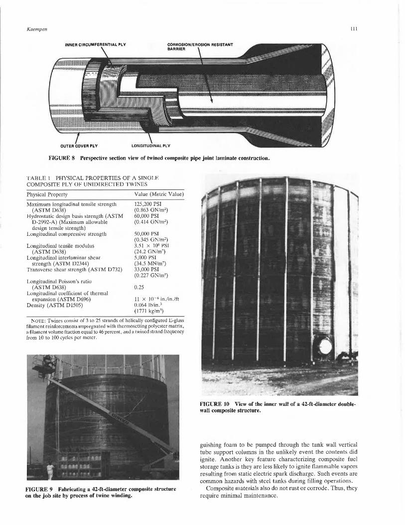
FIGURE 10 View of the inner wall of a 42-ft-diameter doublewall composite structure.
guishing foam to be pumped through the tank wall vertical tube support columns in the unlikely event the contents did ignite . Another key feature characterizing composite fuel storage tanks is they are less likely to ignite flammable vapors resulting from static electric spark discharge. Such events are common hazards with steel tanks during filling operations.
Composite materials also do not rust or corrode. Thus, they require minimal maintenance.
112
FIGURE 11 View of a 42-ft-diameter double-wall composite fuel storage tank.
HOW COMPOSITE STRUCTURES CAN BE USED TO FORM AND REINFORCE CONCRETE
The Aransas Pass, Texas, project demonstrated the feasibility of making large high-performance structures of commercial composites at a cost that is competitive with the same structures made of steel or steel-reinforced concrete. Furthermore, now that the problem of reliable and high-strength connectability has been solved, the innate performance and installation advantages provided by commercial composite structures currently recommend their replacement for steel in future concrete highway projects involving bridges or tunnels.
Figure 12 illustrates a submerged composite-concrete transport tube structure that can serve as a submerged highway tunnel for automotive or railroad traffic. The double-wall composite transport tube provides a convenient pour form by which the concrete is configured into an appropriate structural member able to resist the substantial compression forces imposed by water submersion at significant depths . An inner composite shell provides a second concrete forming structure to shape the tunnel transport space interior. The new class of twined-strand composite material is used to make the outer and inner walls of the transport tube structure, as well as the mechanical coupler assemblies that enable the tube sections to be connected to provide the desired length of highway tunnel. The corrosion resistance provided by the composite
TRANSPORTA TION RESEARCH RECORD 1223
FIGURE 12 Illustration of a submersible composite-reinforced concrete four-track railway tunnel.
structure makes it an ideal material with which to enclose and reinforce concrete that is required to remain serviceable when the structure is exposed to the corrosive effects of seawater.
APPLICATIONS OF COMMERCIAL COMPOSITES TO SUBMERGED RAILWAY TUNNELS
Metropolitan subways and waterway crossings are two specific rail transport projects that can benefit from the use of mechanically connected tubular structures made of commercial composite materials. Both types of rail transport employ tunnels that must be designed to resist a variety of tensile, bending, and compressive loads , including shock loads imposed by earthquakes. Because tubular composite tunnel structures can be easily fabricated by using modern filament processing techniques, they are ideal structural candidates for making use of the unique properties attainable with mechanically coupled tubular structures made of commercial composites.
An example of how commercial composites can be used effectively to solve a modem transportation problem is described in the following paragraphs.
In 1982 a colloquium was held in Madrid to discuss the feasibility of linking Europe with Africa by a fixed transportation link across the Strait of Gibraltar. Although most of the engineering approaches suggested at the colloquium were feasible from an engineering point of view, the primary problem turned out to be one of cost rather than engineering know-
Kaempen
how. It was quickly recognized that such a transport link would not be economically feasible if it were based on the income that would be derived from either freight or passenger traffic diverted from existing ferry and air transport services. The primary justification for such a link would hinge upon its value both to tourism and as a means to provide more rapid transport of certain perishables.
If the link could also encourage future commercial and industrial investment in Spain and Morocco by being associated with advanced technology and engineering, the transport link might also be justified by the prestige associated with such an engineering accomplishment. Furthermore, if the link could also promote fiber optic communications as well as pipeline transport of fuel and potable water, there might be additional commercial justification for such a project.
As the Madrid colloquium made clear, the cost of either a bridge or a tunnel would range from $2 to $6 billion, or perhaps more. The problem with using a bridge as the transport link is twofold: a bridge would impede sea traffic, and the bridge piers would be exposed to collision damage from ships. The problem with using a bored tunnel as the transport link is even more complicated. Earthquakes in the region could affect the tunnel during and after construction. Furthermore, digging the tunnel would be dangerous and would require going to depths greater than had been dug before for such tunnels. At its shallowest part, the strait is 300 m deep. The engineering approaches suggested at the Madrid colloquium did not consider the possibility of using commercial composites as an engineering material that might solve both the engineering problems and the cost problems. Perhaps one reason was simply that a method of connecting and sealing composite structures so that they have the same strength and sealing integrity as a welded steel structure of the same thickness had not yet been developed and proven in service.
Figures 13 through 18 illustrate a submerged compositeconcrete railroad transport tunnel that can provide a fixed link across the Strait of Gibraltar at a fraction of the cost of either a bored tunnel or bridge. It has been determined that a two-track electric railroad tunnel, similar in size to that of the famous 32-mi-long Seikan tunnel in Japan, connecting the
FIGURE 13 Illustration of the proposed Gibraltar Highway submersible tunnel.
------303- ---_...
FIGURE 14 Cross section of the proposed two-track submersible tunnel.
113
480
coast of Spain with the coast of Morocco, can be constructed in less than 4 years at a cost of approximately $500 million.
The submerged transport tube would traverse the "sill" region of the Strait between Malabata near Tangier, Morocco, and Punta Paloma near Tarifa, Spain. This route is approximately 28 km in length and does not exceed a depth of 300 m anywhere along the route. Route geographic details are shown in Figure 19. As currently envisioned, the proposed transport tube would be cylindrical in cross section with an outer diameter of 40 ft (12.18 m) and an interior railroad passage area of 749 sq ft (69.5 sq m). The transport tube would consist of 348 cylindrical double-wall tube sections made entirely of glass-reinforced polyester resin designed to be mechanically connected by a pair of composite mechanical coupling structures, each of which is able to resist a tensile end load of 25,000 lb (4,473 kg) per circumferential in.
The inner wall of the double-wall composite transport tube has a diameter of 32.4 ft (9.87 m). The inner wall is separated from the outer wall by annular composite ribs approximately 1.16 m in height spaced 20 ft (6.14 m) apart.
The annulus of the double-wall composite transport tube is filled with concrete to provide a compression strength capable of resisting submersion to a depth of 1,200 ft (368 m). The weight of the concrete in the annulus plus the weight of concrete forming the rail base structure on which the tracks are laid is sufficient to provide the neccessary stability and negative bouyancy needed to offset a flotation force of approximately 81,000 lb per lineal foot. The transport tube is designed to handle the combined concentrated load of two freight trains each having a length of 1,478 ft (450 m) and a combined weight of 1,100 metric tons.
The transport tube is designed to be anchored to the ocean floor wherever it must be suspended to ensure that the railroad grade does not exceed 2 degrees. Special couplers are used to provide sufficient angular displacement between adjacent coupled tube structures so that the tube structure is sufficiently flexible to accommodate installation variations caused by the irregular ocean floor contour.
SUBMERSIBLE TUNNEL SECTIONS
244&
(62.13
ANNULAR RIBS
2.2 METER
INNER WALL
WALL
COMPOSITE COUPLER/SEAL ASSEMBLIES
FIGURE 15 Side elevation section view of composite transport tubes joined by high-tensile-strength composite couplers.
OUTER COMPOSITE COUPLER
1 RIB
44.75
INNER COMPOSITE COUPLER
240
FIGURE 16 Detail of coupler and rib structure of a composite submersible tunnel structure.
OUTER COUPLER SLEEVES
SECTION VI W OF HALF-GOUPLER
11 11 II II II II
TRANSPO~T TUBE .JOINT NOS
INNER1WALL I
SEAL AND COUPLER ASSV
II II II II 11 II
FIGURE 17 Side elevation section detail of composite coupler assemblies used to join composite tunnel structures.
Kaempen 115
INNER WALL COUPLER SLEEVES
.JOINT END WITH FLARED-END TWINED-STRAND
PLY
WALL HALF-COUPLER
FIGURE 18 Enlargement of section view of tunnel joint seal and coupler.
Each section of the prefabricated double-wall composite tube structure is 240 ft (73 .1 m) long and weighs approximately 400,000 lb (181,000 kg). The coupler assembly used to connect the outer wall structure consists of a two-piece semicylindrical flanged composite coupler member that is held together by two cylindrical composite sleeve members. Each of the coupler halves weighs approximately 3,155 lb (1431 kg) ; each of the cylindrical coupler sleeve members is 30 in . wide and 41 ft in diameter and weighs 4,500 lb (2,042 kg). The coupler assembly used to connect and seal the inner wall structure comprises a two-piece composite flanged semicylindrical coupler member held together by two cylindrical sleeve members . The inner wall of the transport tube section is sealed by a 3-in.-wide compressed rubber seal ring. The weight of the inner wall composite coupler and sleeve structure assembly is approximately 6,000 lb (2722 kg). The rubber seal that withholds an external pressure of at least 600 psi (4.14 MPa) is estimated to weigh less than 400 lb (181.4 kg).
Each section of the proposed composite transport tube would be fabricated on shore in a 600-ft-long shop adjacent to the seashore. The shop would have a concrete floor extending into the sea. The shop floor would provide a 600-ft canal located 4 ft below the sea level at low tide and sealed at the seaward end by a removable dam. After the tube structure has been fabricated, the water would enter into the canal and the tube structure floated out to where it would be anchored offshore a safe distance. Half of the tube structure would be made in Morocco, the other half in Spain. A special barge, designed to serve as a floating dry dock, would be positioned under two floating tube structures and emptied so that the assembly of the couplers and seals could be performed safely above water in the open air. After the tube structures have been connected, they would be sealed at their opposite ends and air tested to check the integrity of the seals. As the line of tubes are assembled along the shores of Spain and Morocco, the sealed ends of each length would be towed together and connected . The floating tube string would be anchored at each shore and then filled with only enough seawater to provide the negative bouyancy to allow it to slowly sink into place. After the transport tube has been properly positioned on the
sea floor, it would be permanently anchored by composite cables attached to the annular ribs comprising each tube section.
The final portion of the construction would begin after the transport tube had been checked out and the structure confirmed to be competent and perfectly sealed. The concrete rail bases would be poured in place and the ballast pumped out. Ventilation would be provided to crews working from either end to lay the railroad tracks and install the electric lights and other utilities. When completed, the tube would be subjected to a rigorous series of tests to ensure its safety and performance while subjected to the tidal action of the water moving into and out of the Mediterranean Sea.
It is estimated that approximately 98 million lb of glass roving and 65 million lb of polyester resin would be required to fabricate the 384 sections of composite transport tube. Those materials are currently available at a cost of approximately $0.90/lb ($2.00/kg). The cost of the concrete would not exceed the cost of the transport tube into which it would be poured. The costs involved in constructing the equipment and training the crews to make and install the tubes is not expected to exceed the total material cost. Because the cost of materials required to make the 28-km-length of transport tube will not exceed $250 million, it is reasonable to expect that the total cost to complete the submerged tunnel railroad link between Europe and Africa would not exceed $500 billion and that it would require no more than 4 years to make and 1 year to test and check out before being placed into service. By removing the concern associated with corrosion of steel or deterioration of concrete exposed to seawater, the proposed submerged composite-concrete transport tube and railroad will probably remain serviceable at least to the year 2200.
OTHER USES OF COMPOSITE TRANSPORT TUBE STRUCTURES
Because prefabricated composite transport tubes of sizes suitable for highway and railroad transport can be individually tested under a variety of service and installation environments before being placed into service, they offer a new approach
116 TRANSPORTATION RESEARCH RECORD 1223
S P A I N
ATLANTIC OCEAN
TANGIER
PUNTA PALOMA
STRAIT OF
"' 0 0 ..J u. < .., V)
z 0 .., <Q
"' ... ... "' 0 0.. V)
z < "' ... ~ -V)
0 0.. a u
"' z 0 ...J
E
"" ~ u. 0 .., ... "' 0
"'
GIBRALTAR
MEDITERRANEAN SEA
MOROCCO 5 KILOMETER
FIGURE 19 The route recommended for installation of a submerged composite railway tunnel.
for solving future transportation problems. They are uniquely suited for constructing temporary or emergency roadways. They can provide the armed forces with traffic or shelter structures that can be deployed by ship to remote areas for rapid installation. They are envisioned as a means by which supersonic surface transport will become attainable because such double-wall transport tubes can be cryogenically evacuated of air while concomitantly employing superconductive materials that make magnetically levitated high-speed trains practical.
CONCLUSION
Use of composites to fabricate tubular double-wall transport tube structures is now economically feasible. The country that becomes a leader in this field of technology will inevitably
benefit from the continuing worldwide growth in passenger and freight traffic. The construction and transport of large structures, such as off-shore platforms and floating hotels, has demonstrated that large-diameter composite transport tubes can be towed and installed virtually anywhere. Where such transport is impractical, the transport tubes can be fabricated on or near their installation site. Shipboard fabrication is even possible by using the equipment, processes, and materials now employed in the fabrication of similar-size composite structures. It is envisioned that composite transport tubes will eventually become a major item of export trade for those · nations that pursue this promising new field of transportation technology.
Publication of this paper sponsored by Task Force on Structural Applications of Fiber Reinforced Plastic.